Embed Size (px)
Citation preview
PRODUCT DATA
65-0238-08
R7999A,B ControLinks™ Controller
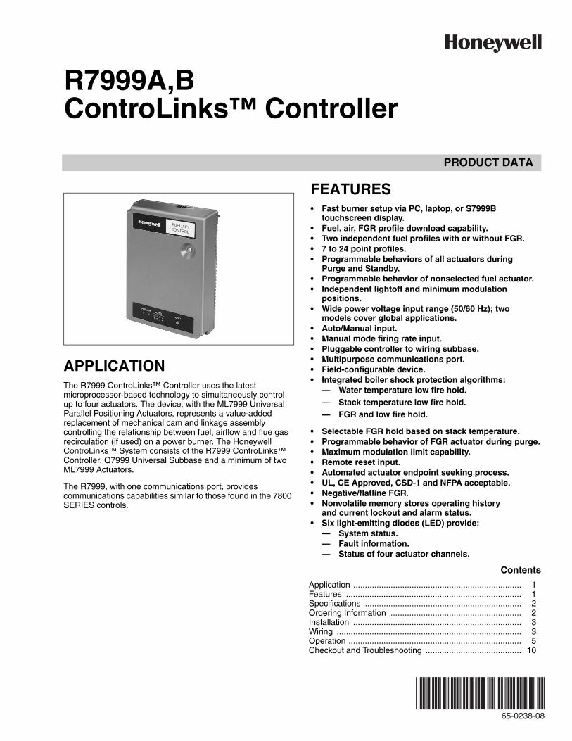
APPLICATIONThe R7999 ControLinks™ Controller uses the latest microprocessor-based technology to simultaneously control up to four actuators. The device, with the ML7999 Universal Parallel Positioning Actuators, represents a value-added replacement of mechanical cam and linkage assembly controlling the relationship between fuel, airflow and flue gas recirculation (if used) on a power burner. The Honeywell ControLinks™ System consists of the R7999 ControLinks™ Controller, Q7999 Universal Subbase and a minimum of two ML7999 Actuators.
The R7999, with one communications port, provides communications capabilities similar to those found in the 7800 SERIES controls.
FEATURES• Fast burner setup via PC, laptop, or S7999B
touchscreen display.• Fuel, air, FGR profile download capability.• Two independent fuel profiles with or without FGR.• 7 to 24 point profiles.• Programmable behaviors of all actuators during
Purge and Standby.• Programmable behavior of nonselected fuel actuator.• Independent lightoff and minimum modulation
positions.• Wide power voltage input range (50/60 Hz); two
models cover global applications.• Auto/Manual input.• Manual mode firing rate input.• Pluggable controller to wiring subbase.• Multipurpose communications port.• Field-configurable device.• Integrated boiler shock protection algorithms:
— Water temperature low fire hold.— Stack temperature low fire hold.— FGR and low fire hold.
• Selectable FGR hold based on stack temperature.• Programmable behavior of FGR actuator during purge.• Maximum modulation limit capability.• Remote reset input.• Automated actuator endpoint seeking process.• UL, CE Approved, CSD-1 and NFPA acceptable.• Negative/flatline FGR.• Nonvolatile memory stores operating history
and current lockout and alarm status.• Six light-emitting diodes (LED) provide:
— System status.— Fault information.— Status of four actuator channels.
Contents
Application ........................................................................ 1Features ........................................................................... 1Specifications ................................................................... 2Ordering Information ........................................................ 2Installation ........................................................................ 3Wiring ............................................................................... 3Operation .......................................................................... 5Checkout and Troubleshooting ......................................... 10
R7999A,B CONTROLINKS™ CONTROLLER
65-0238—08 2
ORDERING INFORMATIONWhen purchasing replacement and modernization products from your TRADELINE® wholesaler or distributor, refer to the TRADELINE® Catalog or price sheets for complete ordering number. If you have additional questions, need further information, or would like to comment on our products or services, please write or phone:
1. Your local Honeywell Environmental and Combustion Controls Sales Office (check white pages of your phone directory).2. Honeywell Customer Care
1885 Douglas Drive NorthMinneapolis, Minnesota 55422-4386
3. http://customer.honeywell.com or http://customer.honeywell.caInternational Sales and Service Offices in all principal cities of the world. Manufacturing in Belgium, Canada, China, Czech Republic, Germany, Hungary, Italy, Mexico, Netherlands, United Kingdom, and United States.
Safety Features• Class C operating software system.• Fail-safe feedback potentiometer circuitry.• Curve verification algorithms.• Step size enforcement during commissioning.• Point plausibility algorithms.• Password protected.• Weld-resistant algorithm for LCI-LCO contact set.• Dual time base.• Built-in self-test and safety relay circuits.• Component anti-swap protection.• Off curve checking algorithm.• 1 million cycle count.• 250,000 hour count.
SPECIFICATIONSModel:R7999A,B ControLinks™ Controller, consisting of a
four-channel actuator drive Input/Output (I/O) and hardware interface for a variety of burner controllers.
Electrical Ratings:Input Power:
R7999A: 100 to 120 Vac (+10/-15%), 50/60 Hz (±10%), 10VA maximum.
R7999B: 200 to 240 Vac (+10/-15%), 50/60 Hz (±10%), 10VA maximum.
Outputs:Limit/Control OUT (LCO):
R7999A: 120 Vac, 8.0A run, 42A inrush (UL).R7999A: 120 Vac, 6.0A run; 26A inrush (CE).R7999B: 240 Vac, 4.0A run, 26A inrush (CE).
Alarm (ALR):R7999A: 120 Vac, 1A pilot duty (UL).R7999A: 120 Vac, 1.0A at PF = 0.4, 6A inrush (CE).R7999B: 240 Vac, 1.0A At PF = 0.4, 6A inrush (CE).
High Fire (HFP):R7999A: 120 Vac, 1A pilot duty (UL)R7999A: 120 Vac, 1A at PF = 0.4, 6A inrush (CE).R7999B: 240 Vac, 1A at PF = 0.4, 6A inrush (CE).
Light-Off Position:R7999A: 120 Vac, 1A pilot duty (UL)R7999A: 120 Vac, 1A at PF = 0.4, 6 A inrush (CE).R7999B: 240 Vac, 1A at PF = 0.4, 6A inrush (CE).
A-1, F1-1, F2-1, FG-1:Source: 4.25 to 5.25V minimum at 5 mA
(counterclockwise [CCW] drive command).Sinking: 0 to 0.6V maximum at -5 mA
(Clockwise [CW] drive command).A-2, F1-2, F2-2, FG-2:
Source: 4.25 to 5.25V minimum at 5 mA (Clockwise [CW] drive command).
Sinking: 0 to 0.6V maximum at -5 mA (Counterclockwise [CCW] drive command).
Inputs:Limit/Control In (LCI)
R7999A: 120 Vac, 8A run, 42A inrush (UL).R7999A: 120 Vac, 6A run, 26A inrush (CE).R7999B: 240 Vac, 4A run, 26A inrush (CE).
Fuel 1 Select (FS1):R7999A: 120 Vac at 2 mA (UL/CE).R7999B: 240 Vac at 2 mA (CE).
Fuel 2 Select (FS2)R7999A: 120 Vac at 2 mA (UL/CE).R7999B: 240 Vac at 2 mA (CE).
Remote Reset (RR): 5V at 5 mA.Feedback Potentiometer input (per channel):
CW: 5 Vdc at 1 mA.S: 5 Vdc at 1 mA.CCW: 5 Vdc at 1 mA.
Environmental Ratings:Temperature Range:Ambient: -40°F to +140°F (-40°C to +60°C).Storage: -40°F to +150°F (-40°C to +65°C).Humidity:
5 to 95 percent relative humidity, noncondensing.Vibration:
0.0 to 0.5g continuous (V2 level).
Mounting: Mounts on Q7999 Universal Subbase.
Enclosure: NEMA1/IP40.
Accessories: 32002515-001 Three-Pin Electrical Connector (RS-485).QM4520A1006 RS-232/RS-485 Converter.DSP3548 Toolkit, including ZM7999 commissioning soft-
ware, computer cable, and RS-232/RS-485 Converter.DSP3822 Display Toolkit. Can be used for programming
ControLinks™ as well as monitoring. Includes S7999B Touchscreen Display.
DSP3956 Toolkit including ZM7999 commissioning soft-ware, computer cable, and USB to 485 converter.
R7999A,B CONTROLINKS™ CONTROLLER
3 65-0238—08
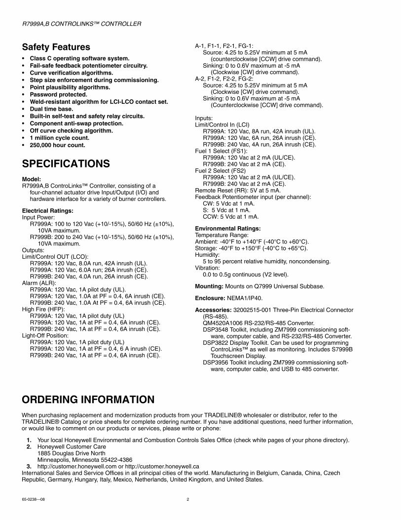
Dimensions: See Fig. 1.
Fig. 1. Approximate dimensions of R7999 ControLinks™ Controller in in. (mm).
Weight: 12oz (0.35 kg).
Approvals:Underwriters Laboratories Inc. cULus: Component
Recognized; File Number MH17367.CE.CSD-1 and NFPA: Acceptable.
Required Components:Q7999 Universal Mounting Subbase.ML7999 Universal Parallel Positioning Actuators (quantity
as required by application).ZM7999 ControLinks™ Software Configuration Tool or S7999B
Touchscreen Display.
INSTALLATION
When Installing This Product...1. Read these instructions carefully. Failure to follow
them could damage the product or cause a hazardous condition.
2. Check the ratings given in the instructions and on the product to make sure the product is suitable for your application.
3. Installer must be a trained, experienced service technician.
4. After installation is complete, check out product operation as provided in these instructions.
WARNINGElectrical Shock Hazard.Can cause serious injury or death.Disconnect power supply before installation.More than one disconnect can be required to remove line voltage power completely.
LocationMount the R7999 on a Q7999 Universal Subbase. The subbase is secured to a panel by four number 8 screws. Secure the R7999 to the subbase by tightening the two captive screws.
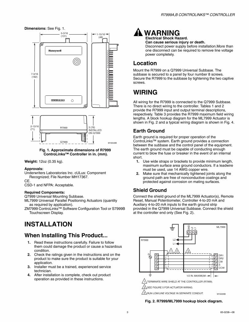
WIRINGAll wiring for the R7999 is connected to the Q7999 Subbase. There is no direct wiring to the controller. Tables 1 and 2 provide the R7999 input and output terminal descriptions, respectively. Table 3 provides the R7999 maximum field wiring lengths. A block hookup diagram for the ML7999 Actuator is shown in Fig. 2 and a typical wiring diagram is shown in Fig. 4.
Earth GroundEarth ground is required for proper operation of the ControLinks™ system. Earth ground provides a connection between the subbase and the control panel of the equipment. The earth ground must be capable of conducting enough current to blow the fuse or breaker in the event of an internal short.
1. Use wide straps or brackets to provide minimum length, maximum surface area ground conductors. If a leadwire must be used, use 14 AWG copper wire.
2. Make sure that mechanically tightened joints along the ground path are free of nonconductive coatings and protected against corrosion on mating surfaces.
Shield GroundConnect the shield ground of the ML7999 Actuator(s), Remote Reset, Manual Potentiometer, Controller 4-to-20 mA and Auxiliary 4-to-20 mA inputs to the earth ground strip provided in the Q7999 Universal Subbase. Connect the shield at the controller end only (See Fig. 2).
Fig. 2. R7999/ML7999 hookup block diagram.
1-15/16(48)
5-3/16(131)
7-3/16(182)
2-13/16(71)
3 (76)INSTALLEDON Q7999
M16548B
R7999
Q7999
GN
DL2 L1
DR1DR2CWSCCW
L2
L1
ML7999
R7999
M16469B
1/2 IN. MAXIMUM
TERMINATE WIRE SHIELD AT THE CONTROLLER (R7999).
SEE FIGURE 5 FOR ACTUATOR WIRING.
RUN LOW/LINE VOLTAGE IN SEPARATE CONDUIT.
1
2
1 2G
3
3
R7999A,B CONTROLINKS™ CONTROLLER
65-0238—08 4
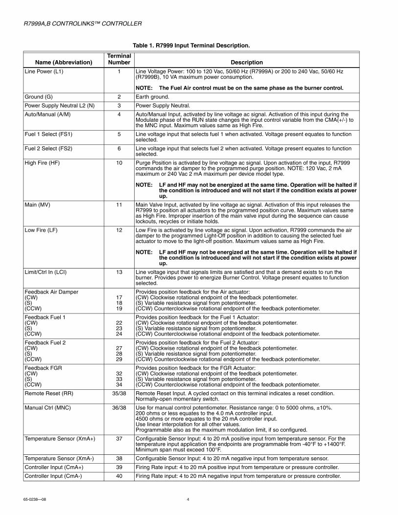
Table 1. R7999 Input Terminal Description.
Name (Abbreviation)Terminal Number Description
Line Power (L1) 1 Line Voltage Power: 100 to 120 Vac, 50/60 Hz (R7999A) or 200 to 240 Vac, 50/60 Hz (R7999B), 10 VA maximum power consumption.
NOTE: The Fuel Air control must be on the same phase as the burner control.
Ground (G) 2 Earth ground.
Power Supply Neutral L2 (N) 3 Power Supply Neutral.
Auto/Manual (A/M) 4 Auto/Manual Input, activated by line voltage ac signal. Activation of this input during the Modulate phase of the RUN state changes the input control variable from the CMA(+/-) to the MNC input. Maximum values same as High Fire.
Fuel 1 Select (FS1) 5 Line voltage input that selects fuel 1 when activated. Voltage present equates to function selected.
Fuel 2 Select (FS2) 6 Line voltage input that selects fuel 2 when activated. Voltage present equates to function selected.
High Fire (HF) 10 Purge Position is activated by line voltage ac signal. Upon activation of the input, R7999 commands the air damper to the programmed purge position. NOTE: 120 Vac, 2 mA maximum or 240 Vac 2 mA maximum per device model type.
NOTE: LF and HF may not be energized at the same time. Operation will be halted if the condition is introduced and will not start if the condition exists at power up.
Main (MV) 11 Main Valve Input, activated by line voltage ac signal. Activation of this input releases the R7999 to position all actuators to the programmed position curve. Maximum values same as High Fire. Improper insertion of the main valve input during the sequence can cause lockouts, recycles or initiate holds.
Low Fire (LF) 12 Low Fire is activated by line voltage ac signal. Upon activation, R7999 commands the air damper to the programmed Light-Off position in addition to causing the selected fuel actuator to move to the light-off position. Maximum values same as High Fire.
NOTE: LF and HF may not be energized at the same time. Operation will be halted if the condition is introduced and will not start if the condition exists at power up.
Limit/Ctrl In (LCI) 13 Line voltage input that signals limits are satisfied and that a demand exists to run the burner. Provides power to energize Burner Control. Voltage present equates to function selected.
Feedback Air Damper(CW)(S)(CCW)
171819
Provides position feedback for the Air actuator:(CW) Clockwise rotational endpoint of the feedback potentiometer.(S) Variable resistance signal from potentiometer.(CCW) Counterclockwise rotational endpoint of the feedback potentiometer.
Feedback Fuel 1(CW)(S)(CCW)
222324
Provides position feedback for the Fuel 1 Actuator:(CW) Clockwise rotational endpoint of the feedback potentiometer.(S) Variable resistance signal from potentiometer.(CCW) Counterclockwise rotational endpoint of the feedback potentiometer.
Feedback Fuel 2(CW)(S)(CCW)
272829
Provides position feedback for the Fuel 2 Actuator:(CW) Clockwise rotational endpoint of the feedback potentiometer.(S) Variable resistance signal from potentiometer.(CCW) Counterclockwise rotational endpoint of the feedback potentiometer.
Feedback FGR(CW)(S)(CCW)
323334
Provides position feedback for the FGR Actuator:(CW) Clockwise rotational endpoint of the feedback potentiometer.(S) Variable resistance signal from potentiometer.(CCW) Counterclockwise rotational endpoint of the feedback potentiometer.
Remote Reset (RR) 35/38 Remote Reset Input. A cycled contact on this terminal indicates a reset condition. Normally-open momentary switch.
Manual Ctrl (MNC) 36/38 Use for manual control potentiometer. Resistance range: 0 to 5000 ohms, ±10%.200 ohms or less equates to the 4.0 mA controller input.4500 ohms or more equates to the 20 mA controller input.Use linear interpolation for all other values.Programmable also as the maximum modulation limit, if so configured.
Temperature Sensor (XmA+) 37 Configurable Sensor Input: 4 to 20 mA positive input from temperature sensor. For the temperature input application the endpoints are programmable from -40°F to +1400°F. Minimum span must exceed 100°F.
Temperature Sensor (XmA-) 38 Configurable Sensor Input: 4 to 20 mA negative input from temperature sensor.
Controller Input (CmA+) 39 Firing Rate input: 4 to 20 mA positive input from temperature or pressure controller.
Controller Input (CmA-) 40 Firing Rate input: 4 to 20 mA negative input from temperature or pressure controller.
R7999A,B CONTROLINKS™ CONTROLLER
5 65-0238—08
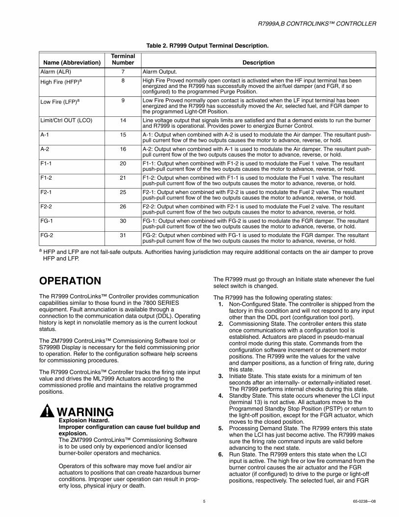
Table 2. R7999 Output Terminal Description.
a HFP and LFP are not fail-safe outputs. Authorities having jurisdiction may require additional contacts on the air damper to prove HFP and LFP.
OPERATIONThe R7999 ControLinks™ Controller provides communication capabilities similar to those found in the 7800 SERIES equipment. Fault annunciation is available through a connection to the communication data output (DDL). Operating history is kept in nonvolatile memory as is the current lockout status.
The ZM7999 ControLinks™ Commissioning Software tool or S7999B Display is necessary for the field commissioning prior to operation. Refer to the configuration software help screens for commissioning procedures.
The R7999 ControLinks™ Controller tracks the firing rate input value and drives the ML7999 Actuators according to the commissioned profile and maintains the relative programmed positions.
WARNINGExplosion Hazard.Improper configuration can cause fuel buildup and explosion.The ZM7999 ControLinks™ Commissioning Software is to be used only by experienced and/or licensed burner-boiler operators and mechanics.
Operators of this software may move fuel and/or air actuators to positions that can create hazardous burner conditions. Improper user operation can result in prop-erty loss, physical injury or death.
The R7999 must go through an Initiate state whenever the fuel select switch is changed.
The R7999 has the following operating states:1. Non-Configured State. The controller is shipped from the
factory in this condition and will not respond to any input other than the DDL port (configuration tool port).
2. Commissioning State. The controller enters this state once communications with a configuration tool is established. Actuators are placed in pseudo-manual control mode during this state. Commands from the configuration software increment or decrement motor positions. The R7999 write the values for the valve and damper positions, as a function of firing rate, during this state.
3. Initiate State. This state exists for a minimum of ten seconds after an internally- or externally-initiated reset. The R7999 performs internal checks during this state.
4. Standby State. This state occurs whenever the LCI input (terminal 13) is not active. All actuators move to the Programmed Standby Stop Position (PSTP) or return to the light-off position, except for the FGR actuator, which moves to the closed position.
5. Processing Demand State. The R7999 enters this state when the LCI has just become active. The R7999 makes sure the firing rate command inputs are valid before advancing to the next state.
6. Run State. The R7999 enters this state when the LCI input is active. The high fire or low fire command from the burner control causes the air actuator and the FGR actuator (if configured) to drive to the purge or light-off positions, respectively. The selected fuel, air and FGR
Name (Abbreviation)Terminal Number Description
Alarm (ALR) 7 Alarm Output.
High Fire (HFP)a 8 High Fire Proved normally open contact is activated when the HF input terminal has been energized and the R7999 has successfully moved the air/fuel damper (and FGR, if so configured) to the programmed Purge Position.
Low Fire (LFP)a 9 Low Fire Proved normally open contact is activated when the LF input terminal has been energized and the R7999 has successfully moved the Air, selected fuel, and FGR damper to the programmed Light-Off Position.
Limit/Ctrl OUT (LCO) 14 Line voltage output that signals limits are satisfied and that a demand exists to run the burner and R7999 is operational. Provides power to energize Burner Control.
A-1 15 A-1: Output when combined with A-2 is used to modulate the Air damper. The resultant push-pull current flow of the two outputs causes the motor to advance, reverse, or hold.
A-2 16 A-2: Output when combined with A-1 is used to modulate the Air damper. The resultant push-pull current flow of the two outputs causes the motor to advance, reverse, or hold.
F1-1 20 F1-1: Output when combined with F1-2 is used to modulate the Fuel 1 valve. The resultant push-pull current flow of the two outputs causes the motor to advance, reverse, or hold.
F1-2 21 F1-2: Output when combined with F1-1 is used to modulate the Fuel 1 valve. The resultant push-pull current flow of the two outputs causes the motor to advance, reverse, or hold.
F2-1 25 F2-1: Output when combined with F2-2 is used to modulate the Fuel 2 valve. The resultant push-pull current flow of the two outputs causes the motor to advance, reverse, or hold.
F2-2 26 F2-2: Output when combined with F2-1 is used to modulate the Fuel 2 valve. The resultant push-pull current flow of the two outputs causes the motor to advance, reverse, or hold.
FG-1 30 FG-1: Output when combined with FG-2 is used to modulate the FGR damper. The resultant push-pull current flow of the two outputs causes the motor to advance, reverse, or hold.
FG-2 31 FG-2: Output when combined with FG-1 is used to modulate the FGR damper. The resultant push-pull current flow of the two outputs causes the motor to advance, reverse, or hold.
R7999A,B CONTROLINKS™ CONTROLLER
65-0238—08 6
actuators track the firing rate input versus the programmed profile once the main valve terminal is energized.
7. Lockout State. The R7999 enters this state when critical internal faults are detected. The controller retains the lockout state via nonvolatile memory. To exit this state, press the reset button.
8. Alarm Initiate State. Essentially an Initiate state, except that the alarm terminal is energized. A controller will remain in this state as long as the fault exists. The R7999 will automatically restart once the fault is removed. The user may restart the system by pressing the Reset but-ton.
Normal operating sequence for the R7999 is: Initiate (ac power up or internal or external reset), Standby, Processing Demand and Run. The Non-Configured State may also occur.
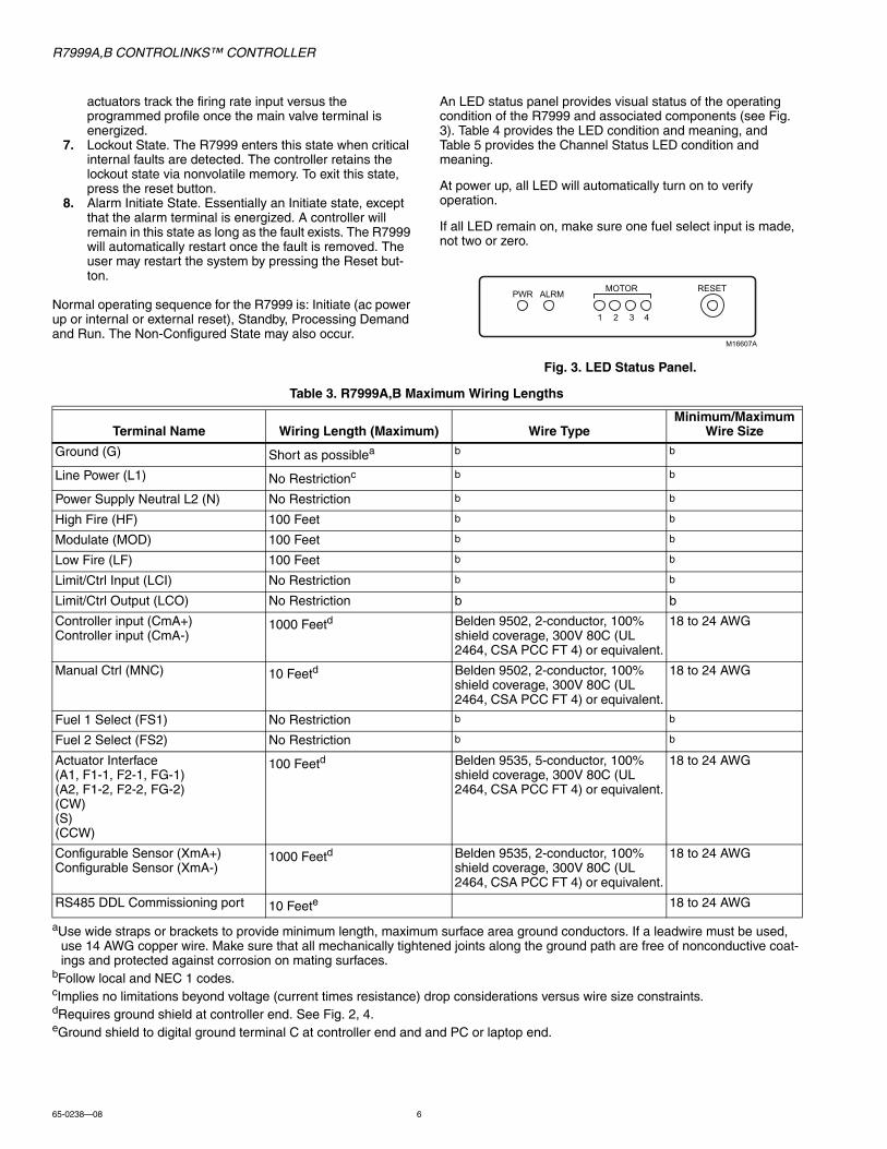
An LED status panel provides visual status of the operating condition of the R7999 and associated components (see Fig. 3). Table 4 provides the LED condition and meaning, and Table 5 provides the Channel Status LED condition and meaning.
At power up, all LED will automatically turn on to verify operation.
If all LED remain on, make sure one fuel select input is made, not two or zero.
Fig. 3. LED Status Panel.
Table 3. R7999A,B Maximum Wiring Lengths
aUse wide straps or brackets to provide minimum length, maximum surface area ground conductors. If a leadwire must be used, use 14 AWG copper wire. Make sure that all mechanically tightened joints along the ground path are free of nonconductive coat-ings and protected against corrosion on mating surfaces.
bFollow local and NEC 1 codes.cImplies no limitations beyond voltage (current times resistance) drop considerations versus wire size constraints.dRequires ground shield at controller end. See Fig. 2, 4.eGround shield to digital ground terminal C at controller end and and PC or laptop end.
ALRMPWR
1 2 3 4
MOTOR RESET
M16607A
Terminal Name Wiring Length (Maximum) Wire TypeMinimum/Maximum
Wire Size
Ground (G) Short as possiblea b b
Line Power (L1) No Restrictionc b b
Power Supply Neutral L2 (N) No Restriction b b
High Fire (HF) 100 Feet b b
Modulate (MOD) 100 Feet b b
Low Fire (LF) 100 Feet b b
Limit/Ctrl Input (LCI) No Restriction b b
Limit/Ctrl Output (LCO) No Restriction b b
Controller input (CmA+)Controller input (CmA-)
1000 Feetd Belden 9502, 2-conductor, 100% shield coverage, 300V 80C (UL 2464, CSA PCC FT 4) or equivalent.
18 to 24 AWG
Manual Ctrl (MNC) 10 Feetd Belden 9502, 2-conductor, 100% shield coverage, 300V 80C (UL 2464, CSA PCC FT 4) or equivalent.
18 to 24 AWG
Fuel 1 Select (FS1) No Restriction b b
Fuel 2 Select (FS2) No Restriction b b
Actuator Interface(A1, F1-1, F2-1, FG-1)(A2, F1-2, F2-2, FG-2)(CW)(S)(CCW)
100 Feetd Belden 9535, 5-conductor, 100% shield coverage, 300V 80C (UL 2464, CSA PCC FT 4) or equivalent.
18 to 24 AWG
Configurable Sensor (XmA+)Configurable Sensor (XmA-)
1000 Feetd Belden 9535, 2-conductor, 100% shield coverage, 300V 80C (UL 2464, CSA PCC FT 4) or equivalent.
18 to 24 AWG
RS485 DDL Commissioning port 10 Feete 18 to 24 AWG
R7999A,B CONTROLINKS™ CONTROLLER
7 65-0238—08
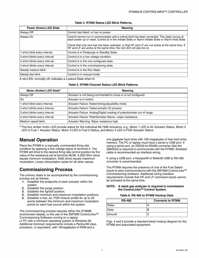
Table 4. R7999 Status LED Blink Patterns.
A red LED, normally off, indicates a Lockout State when lit.
Table 5. R7999 Channel Status LED Blink Patterns.
a The four amber motor LED provide status for the individual ML7999 Actuators; e.g., Motor 1 LED is Air Actuator Status, Motor 2 LED is Fuel 1 Actuator Status, Motor 3 LED is Fuel 2 Status, and Motor 4 LED is FGR Actuator Status.
Manual OperationPlace the R7999 in a manually commanded firing rate condition by applying a line voltage signal to terminal 4. The R7999 will drive to the desired firing rate control position by the value of the resistance set at terminal 36/38. A 200-Ohm value equals minimum modulation; 4500 ohms equals maximum modulation. Linear interpolation exists for all other values.
Commissioning ProcessThe primary tasks to be accomplished by the commissioning process are as follows:
1. Establish the endpoints of each actuator within the system.
2. Establish the purge position.3. Establish the lightoff position.4. Establish minimum and maximum modulation positions.5. Establish a fuel, air, FGR mixture profile for up to 20
points between the minimum and maximum modulation points for each fuel source within the system.
The commissioning process requires either the S7999B touchscreen display, or the use of the ZM7999 ControLinks™ Commissioning Software running on a laptop or PC with a minimum operating system of Windows 95. Additional minimum requirements include a Pentium® class processor, or equivalent, with 16megabytes of RAM and a
one gigabyte hard drive with 100 megabytes of free hard drive memory. The PC or laptop must have a serial or USB port. If using a serial port, an RS232-to-RS485 converter (like the QM4520) is required to communicate with the R7999. Shielded cable is recommended as interface wiring.
If using a USB port, a Keyspan® or Belkin® USB to RS-485 converter is recommended.
The R7999 requires the presence of one of the Fuel Select inputs to start communications with the ZM7999 ControLinks™ Commissioning Software. Additional wiring interface requirements include that HF and LF command inputs cannot be activated at the same time.
NOTE: A stack gas analyzer is required to commission the ControLinks™ Control System.
Table 6. RS-485 to R7999 Hookup Data.
Figs. 4 and 5 provide a standard block hookup diagram for the R7999 and associated equipment.
Power (Green) LED State Meaning
Always Off Control has failed, or has no power.
Always On Control cannot run or communicate until a critical fault has been corrected. This state occurs at each power up or reset. Control is in the Initiate State or Alarm Initiate State or Alarm Hold State.
Check that only one fuel has been selected, or that HF and LF are not active at the same time. If HF and LF are active at the same time, the red LED will also be on.
1 short blink every interval Control is in Postpurge or Standby State.
2 short blinks every interval Control is in a low voltage condition.
3 short blinks every interval Control is in the non-configured state.
4 short blinks every interval Control is in the commissioning state.
Steady medium blink Control is in the Run State.
Steady fast blink Control is in manual mode.
Motor (Amber) LED Statea Meaning
Always Off Actuator is not being commanded to move or is not configured.
On Actuator is in motion.
1 short blink every interval. Actuator Failure: Failed timing plausibility check.
2 short blinks every interval. Actuator Failure: Failed actuator ID process.
3 short blinks every interval. Actuator Failure: Analog/Digital reading of potentiometer out of range.
4 short blinks every interval Actuator Failure: Potentiometer failure—wiper resistance.
Medium speed blink. Actuator Warning: Wiper resistance high.
RS-485 Connects to R7999
Data+ A
Data- B
Ground C
R7999A,B CONTROLINKS™ CONTROLLER
65-0238—08 8
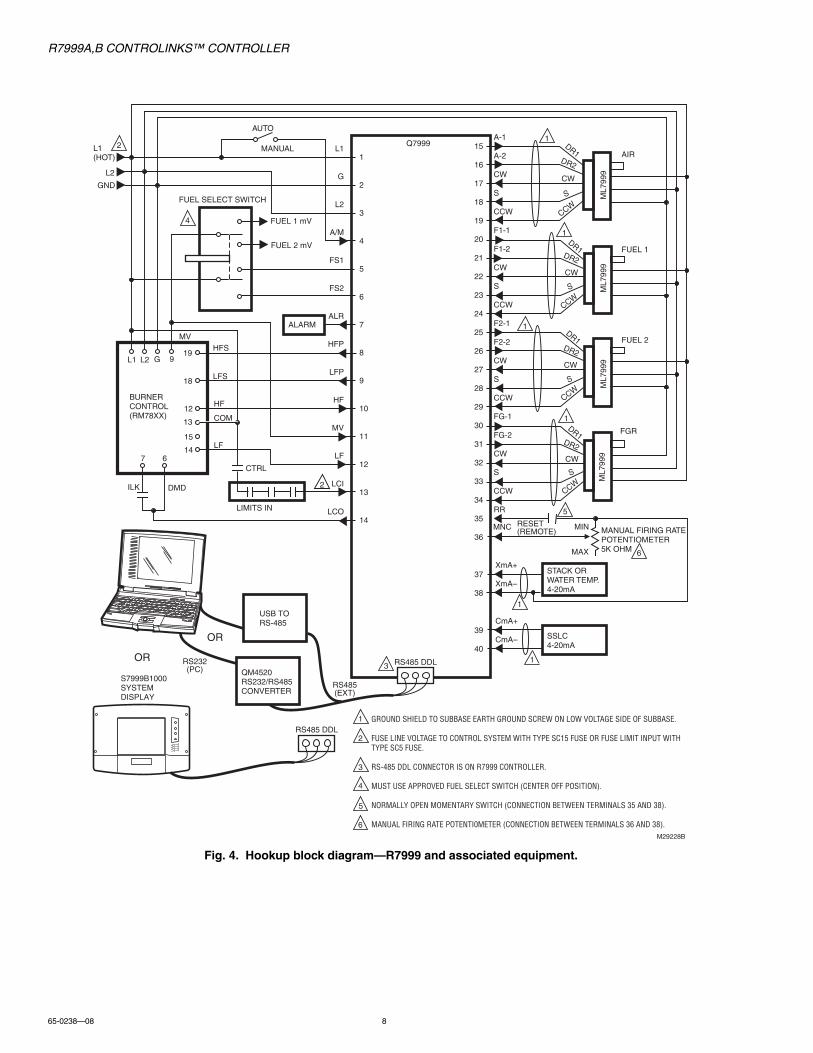
Fig. 4. Hookup block diagram—R7999 and associated equipment.
RS485 DDL
15
16
17
18
19
20
21
22
23
24
25
26
27
28
29
30
31
32
33
34
35
36
37
38
39
40
STACK ORWATER TEMP.4-20mA
SSLC4-20mA
A-1
A-2
CW
S
CCW
F1-1
F1-2
CW
S
CCW
F2-1
F2-2
CW
S
CCW
FG-1
FG-2
CW
S
CCW
RR
XmA+
XmA–
CmA+
CmA–
FUEL 1
AIR
FUEL 2
FGR
MAX
MINRESET (REMOTE)
RS485 DDL
1
2
3
4
5
6
7
8
9
10
11
12
13
14
BURNERCONTROL(RM78XX)
CTRL
LIMITS IN
ILK DMD
ALARM
HFS
LFS
HF
COM
LF
MANUAL FIRING RATEPOTENTIOMETER5K OHM
L1(HOT)
L2
GND
AUTO
MANUALQ7999
L1
G
L2
A/M
FS1
FS2
ALR
HFP
LFP
HF
MV
LF
LCI
LCO
M29228B
MV
FUEL SELECT SWITCH
FUEL 1 mV
FUEL 2 mV
1
1
1
1
1
1
2
3
4
4
3
2
2
GROUND SHIELD TO SUBBASE EARTH GROUND SCREW ON LOW VOLTAGE SIDE OF SUBBASE.
FUSE LINE VOLTAGE TO CONTROL SYSTEM WITH TYPE SC15 FUSE OR FUSE LIMIT INPUT WITH TYPE SC5 FUSE.
RS-485 DDL CONNECTOR IS ON R7999 CONTROLLER.
MUST USE APPROVED FUEL SELECT SWITCH (CENTER OFF POSITION).
NORMALLY OPEN MOMENTARY SWITCH (CONNECTION BETWEEN TERMINALS 35 AND 38).
MANUAL FIRING RATE POTENTI0METER (CONNECTION BETWEEN TERMINALS 36 AND 38).
L1 L2 G 919
18
12
13
15
147 6
DR1
DR1
DR1
DR1
DR2
DR2
DR2
DR2
CW
CW
CW
CW
S
S
S
S
CCW
CCW
CCW
CCW
RS232(PC)
RS485(EXT)
ML7
999
ML7
999
ML7
999
ML7
999
1
5
5
MNC
6
6
QM4520RS232/RS485CONVERTER
S7999B1000SYSTEMDISPLAY
OR
USB TO RS-485
OR
R7999A,B CONTROLINKS™ CONTROLLER
9 65-0238—08
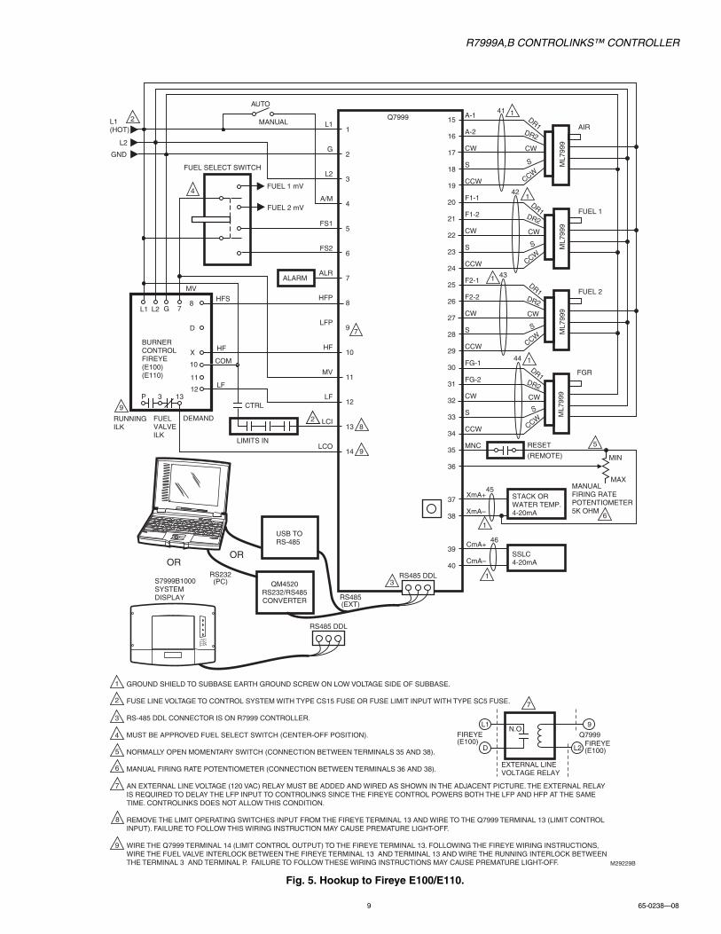
Fig. 5. Hookup to Fireye E100/E110.
15
16
17
18
19
20
21
22
23
24
25
26
27
28
29
30
31
32
33
34
35
36
37
38
39
40
STACK ORWATER TEMP.4-20mA
SSLC4-20mA
A-1
A-2
CW
S
CCW
F1-1
F1-2
CW
S
CCW
F2-1
F2-2
CW
S
CCW
FG-1
FG-2
CW
S
CCW
MNC
XmA+
XmA–
CmA+
CmA–
FUEL 1
AIR
FUEL 2
FGR
MAX
MIN
RESET
(REMOTE)
RS485 DDL
1
2
3
4
5
6
7
8
9
10
11
12
13
14
BURNERCONTROLFIREYE(E100)(E110)
CTRL
LIMITS IN
FUELVALVEILK
DEMAND
ALARM
HFS
HF
COM
LF
MANUALFIRING RATEPOTENTIOMETER5K OHM
L1(HOT)
L2
GND
Q7999L1
G
L2
A/M
FS1
FS2
ALR
HFP
LFP
HF
MV
LF
LCI
LCO
M29229B
MV
FUEL SELECT SWITCH
FUEL 1 mV
FUEL 2 mV
1
1
1
1
5
1
1
2
3
4
7
3
2
241
42
43
44
45
46
GROUND SHIELD TO SUBBASE EARTH GROUND SCREW ON LOW VOLTAGE SIDE OF SUBBASE.
FUSE LINE VOLTAGE TO CONTROL SYSTEM WITH TYPE CS15 FUSE OR FUSE LIMIT INPUT WITH TYPE SC5 FUSE.
RS-485 DDL CONNECTOR IS ON R7999 CONTROLLER.
MUST BE APPROVED FUEL SELECT SWITCH (CENTER-OFF POSITION).
NORMALLY OPEN MOMENTARY SWITCH (CONNECTION BETWEEN TERMINALS 35 AND 38).
MANUAL FIRING RATE POTENTIOMETER (CONNECTION BETWEEN TERMINALS 36 AND 38).
AN EXTERNAL LINE VOLTAGE (120 VAC) RELAY MUST BE ADDED AND WIRED AS SHOWN IN THE ADJACENT PICTURE. THE EXTERNAL RELAY IS REQUIRED TO DELAY THE LFP INPUT TO CONTROLINKS SINCE THE FIREYE CONTROL POWERS BOTH THE LFP AND HFP AT THE SAME TIME. CONTROLINKS DOES NOT ALLOW THIS CONDITION.
REMOVE THE LIMIT OPERATING SWITCHES INPUT FROM THE FIREYE TERMINAL 13 AND WIRE TO THE Q7999 TERMINAL 13 (LIMIT CONTROL INPUT). FAILURE TO FOLLOW THIS WIRING INSTRUCTION MAY CAUSE PREMATURE LIGHT-OFF.
WIRE THE Q7999 TERMINAL 14 (LIMIT CONTROL OUTPUT) TO THE FIREYE TERMINAL 13. FOLLOWING THE FIREYE WIRING INSTRUCTIONS, WIRE THE FUEL VALVE INTERLOCK BETWEEN THE FIREYE TERMINAL 13 AND TERMINAL 13 AND WIRE THE RUNNING INTERLOCK BETWEEN THE TERMINAL 3 AND TERMINAL P. FAILURE TO FOLLOW THESE WIRING INSTRUCTIONS MAY CAUSE PREMATURE LIGHT-OFF.
L1 L2 G 78
D
X
10
11
123 13P
DR1
DR1
DR1
DR1
DR2
DR2
DR2
DR2
CW
CW
CW
CW
S
S
S
S
CCW
CCW
CCW
CCW
ML7
999
ML7
999
ML7
999
ML7
999
L1
D
9
L2
Q7999FIREYE(E100)
FIREYE(E100)
EXTERNAL LINE VOLTAGE RELAY
N.O.
5
6
7
8
9
9
8
7
61
4
9
RUNNINGILK
RS485 DDL
RS232(PC) QM4520
RS232/RS485CONVERTER
S7999B1000SYSTEMDISPLAY
OR
RS485(EXT)
USB TO RS-485
OR
AUTO
MANUAL
R7999A,B CONTROLINKS™ CONTROLLER
65-0238—08 10
CHECKOUT AND TROUBLESHOOTING
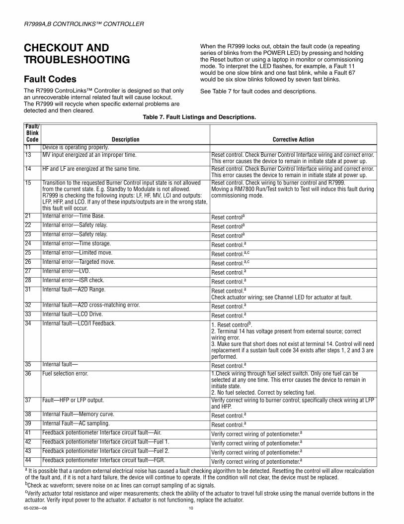
Fault CodesThe R7999 ControLinks™ Controller is designed so that only an unrecoverable internal related fault will cause lockout. The R7999 will recycle when specific external problems are detected and then cleared.
When the R7999 locks out, obtain the fault code (a repeating series of blinks from the POWER LED) by pressing and holding the Reset button or using a laptop in monitor or commissioning mode. To interpret the LED flashes, for example, a Fault 11 would be one slow blink and one fast blink, while a Fault 67 would be six slow blinks followed by seven fast blinks.
See Table 7 for fault codes and descriptions.
Table 7. Fault Listings and Descriptions.
Fault/Blink Code Description Corrective Action11 Device is operating properly.13 MV input energized at an improper time. Reset control. Check Burner Control Interface wiring and correct error.
This error causes the device to remain in initiate state at power up.14 HF and LF are energized at the same time. Reset control. Check Burner Control Interface wiring and correct error.
This error causes the device to remain in initiate state at power up.15 Transition to the requested Burner Control input state is not allowed
from the current state. E.g. Standby to Modulate is not allowed.R7999 is checking the following inputs: LF, HF, MV, LCI and outputs: LFP, HFP, and LCO. If any of these inputs/outputs are in the wrong state, this fault will occur.
Reset control. Check wiring to burner control and R7999.Moving a RM7800 Run/Test switch to Test will induce this fault during commissioning mode.
21 Internal error—Time Base. Reset controla
22 Internal error—Safety relay. Reset controla
23 Internal error—Safety relay. Reset controla
24 Internal error—Time storage. Reset control.a
25 Internal error—Limited move. Reset control.a,c
26 Internal error—Targeted move. Reset control.a,c
27 Internal error—LVD. Reset control.a
28 Internal error—ISR check. Reset control.a
31 Internal fault—A2D Range. Reset control.a
Check actuator wiring; see Channel LED for actuator at fault.32 Internal fault—A2D cross-matching error. Reset control.a
33 Internal fault—LCO Drive. Reset control.a
34 Internal fault—LCO/I Feedback. 1. Reset controlb.2. Terminal 14 has voltage present from external source; correct wiring error.3. Make sure that short does not exist at terminal 14. Control will need replacement if a sustain fault code 34 exists after steps 1, 2 and 3 are performed.
35 Internal fault— Reset control.a
36 Fuel selection error. 1.Check wiring through fuel select switch. Only one fuel can be selected at any one time. This error causes the device to remain in initiate state.2. No fuel selected. Correct by selecting fuel.
37 Fault—HFP or LFP output. Verify correct wiring to burner control; specifically check wiring at LFP and HFP.
38 Internal Fault—Memory curve. Reset control.a
39 Internal Fault—AC sampling. Reset control.a
41 Feedback potentiometer Interface circuit fault—Air. Verify correct wiring of potentiometer.a
42 Feedback potentiometer Interface circuit fault—Fuel 1. Verify correct wiring of potentiometer.a
43 Feedback potentiometer Interface circuit fault—Fuel 2. Verify correct wiring of potentiometer.a
44 Feedback potentiometer Interface circuit fault—FGR. Verify correct wiring of potentiometer.aa It is possible that a random external electrical noise has caused a fault checking algorithm to be detected. Resetting the control will allow recalculation of the fault and, if it is not a hard failure, the device will continue to operate. If the condition will not clear, the device must be replaced.bCheck ac waveform; severe noise on ac lines can corrupt sampling of ac signals.cVerify actuator total resistance and wiper measurements; check the ability of the actuator to travel full stroke using the manual override buttons in the actuator. Verify input power to the actuator. if actuator is not functioning, replace the actuator.
R7999A,B CONTROLINKS™ CONTROLLER
11 65-0238—08
45 Feedback potentiometer wiper resistance problem—Air. Check for loose potentiometer wiring.a,c
46 Feedback potentiometer wiper resistance problem—Fuel 1. Check for loose potentiometer wiring.a,c
47 Feedback potentiometer wiper resistance problem—Fuel 2. Check for loose potentiometer wiring.a,c
48 Feedback potentiometer wiper resistance problem—FGR. Check for loose potentiometer wiring.a,c
49 Feedback potentiometer total resistance problem—Air. Check for loose potentiometer wiring.a,c
51 Feedback potentiometer total resistance problem—Fuel 1. Check for loose potentiometer wiring.a,c
52 Feedback potentiometer total resistance problem—Fuel 2. Check for loose potentiometer wiring.a,c
53 Feedback potentiometer total resistance problem—FGR. Check for loose potentiometer wiring.a,c
54 Internal memory function problem—Air. Repeat actuator ID on-line process.55 Internal memory function problem—Fuel 1. Repeat actuator ID on-line process.56 Internal memory function problem—Fuel 2. Repeat actuator ID on-line process.57 Internal memory function problem—FGR. Repeat actuator ID on-line process.58 Stuck Reset button. Turn off remote reset switch; check operation of controller reset button.61 Actuator(s) not reaching lightoff point. Check for actuator wiring problems or stuck valves or dampers. Place
controller in standby and use actuator manual keys to verify actuator travel.65 Internal memory fault. Reset control.a
66 Internal Initialization Error. Reset control.a
67 Fuel actuator off curve (selected fuel type). Check for stuck fuel actuator and/or proper shielding on actuator interface.68 FGR actuator off curve. Check for stuck FGR actuator and/or proper shielding on actuator interface.69 Air actuator off curve. Check for stuck air actuator and/or proper shielding on actuator interface.71 Verifies that the Air actuator accepted the offline, online, move counter-
clock-wise and move clock-wise commands. Furthermore, all potentiometer tests must be successfully passed to bring an actuator online.
Check wiring of actuator, verify correct ID is being used. Watch actuator LED to verify that the actuator is being brought online. A fast flash in the actuator equals offline status, while a one-second flash equals online status.
72 Verifies that the Fuel 1 actuator accepted the offline, online, move counter-clock-wise and move clock-wise commands. Furthermore, all potentiometer tests must be successfully passed to bring an actuator online.
Check wiring of actuator, verify correct ID is being used. Watch actuator LED to verify that the actuator is being brought online. A fast flash in the actuator equals offline status, while a one-second flash equals online status.
73 Verifies that the Fuel 2 actuator accepted the offline, online, move counter-clock-wise and move clock-wise commands. Furthermore, all potentiometer tests must be successfully passed to bring an actuator online.
Check wiring of actuator, verify correct ID is being used. Watch actuator LED to verify that the actuator is being brought online. A fast flash in the actuator equals offline status, while a one-second flash equals online status.
74 Verifies that the FGR actuator accepted the offline, online, move counter-clock-wise and move clock-wise commands. Furthermore, all potentiometer tests must be successfully passed to bring an actuator online.
Check wiring of actuator, verify correct ID is being used. Watch actuator LED to verify that the actuator is being brought online. A fast flash in the actuator equals offline status, while a one-second flash equals online status.
75 Internal memory fault. Reset control.a
76 Internal checksum error. Reset control.a
82 Actuator secondary fault. Check actuator wiring. See Channel LED for actuator.83 Air actuator nonresponsive. Check actuator wiring and stuck damper/valve.c
84 Fuel 1 actuator nonresponsive. Check actuator wiring and stuck damper/valve.c
85 Fuel 2 actuator nonresponsive. Check actuator wiring and stuck damper/valve.c
86 FGR actuator nonresponsive. Check actuator wiring and stuck damper/valve.c
87 Internal math error. Reset control.a
91 The 4 to 20 mA firing rate input is below 3 mA, Out of Range—Low. (Actuators return to or remain at the minimum modulation point with the alarm on; the control remains operational only to the extent that Minimum Modulation firing operation is allowed.)
Check CmA+-input (Terminals 39 and 40) for proper operation polarity and range. The input must be within 3.0 mA to 21.0 mA. The voltage at this terminal must be within 0.7 to 5.0 Vdc, respectively.Conditional Alarm—Alarm output is energized; controller continues to run.
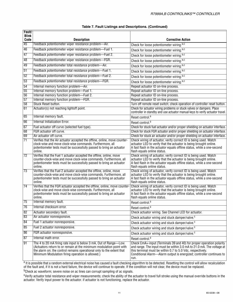
Table 7. Fault Listings and Descriptions. (Continued)
Fault/Blink Code Description Corrective Action
a It is possible that a random external electrical noise has caused a fault checking algorithm to be detected. Resetting the control will allow recalculation of the fault and, if it is not a hard failure, the device will continue to operate. If the condition will not clear, the device must be replaced.bCheck ac waveform; severe noise on ac lines can corrupt sampling of ac signals.cVerify actuator total resistance and wiper measurements; check the ability of the actuator to travel full stroke using the manual override buttons in the actuator. Verify input power to the actuator. if actuator is not functioning, replace the actuator.
R7999A,B CONTROLINKS™ CONTROLLER
Automation and Control SolutionsHoneywell International Inc.
1985 Douglas Drive North
Golden Valley, MN 55422
customer.honeywell.com
® U.S. Registered Trademark© 2011 Honeywell International Inc.65-0238—08 M.S. Rev. 08-11 Printed in United States
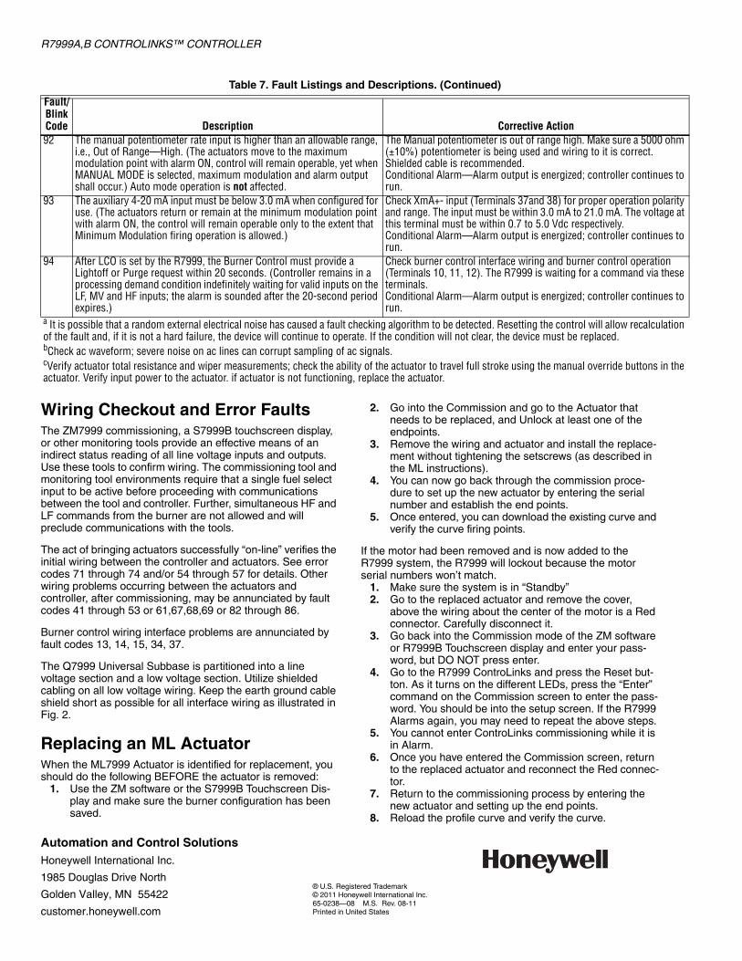
Wiring Checkout and Error FaultsThe ZM7999 commissioning, a S7999B touchscreen display, or other monitoring tools provide an effective means of an indirect status reading of all line voltage inputs and outputs. Use these tools to confirm wiring. The commissioning tool and monitoring tool environments require that a single fuel select input to be active before proceeding with communications between the tool and controller. Further, simultaneous HF and LF commands from the burner are not allowed and will preclude communications with the tools.
The act of bringing actuators successfully “on-line” verifies the initial wiring between the controller and actuators. See error codes 71 through 74 and/or 54 through 57 for details. Other wiring problems occurring between the actuators and controller, after commissioning, may be annunciated by fault codes 41 through 53 or 61,67,68,69 or 82 through 86.
Burner control wiring interface problems are annunciated by fault codes 13, 14, 15, 34, 37.
The Q7999 Universal Subbase is partitioned into a line voltage section and a low voltage section. Utilize shielded cabling on all low voltage wiring. Keep the earth ground cable shield short as possible for all interface wiring as illustrated in Fig. 2.
Replacing an ML ActuatorWhen the ML7999 Actuator is identified for replacement, you should do the following BEFORE the actuator is removed:
1. Use the ZM software or the S7999B Touchscreen Dis-play and make sure the burner configuration has been saved.
2. Go into the Commission and go to the Actuator that needs to be replaced, and Unlock at least one of the endpoints.
3. Remove the wiring and actuator and install the replace-ment without tightening the setscrews (as described in the ML instructions).
4. You can now go back through the commission proce-dure to set up the new actuator by entering the serial number and establish the end points.
5. Once entered, you can download the existing curve and verify the curve firing points.
If the motor had been removed and is now added to the R7999 system, the R7999 will lockout because the motor serial numbers won’t match.
1. Make sure the system is in “Standby”2. Go to the replaced actuator and remove the cover,
above the wiring about the center of the motor is a Red connector. Carefully disconnect it.
3. Go back into the Commission mode of the ZM software or R7999B Touchscreen display and enter your pass-word, but DO NOT press enter.
4. Go to the R7999 ControLinks and press the Reset but-ton. As it turns on the different LEDs, press the “Enter” command on the Commission screen to enter the pass-word. You should be into the setup screen. If the R7999 Alarms again, you may need to repeat the above steps.
5. You cannot enter ControLinks commissioning while it is in Alarm.
6. Once you have entered the Commission screen, return to the replaced actuator and reconnect the Red connec-tor.
7. Return to the commissioning process by entering the new actuator and setting up the end points.
8. Reload the profile curve and verify the curve.
92 The manual potentiometer rate input is higher than an allowable range, i.e., Out of Range—High. (The actuators move to the maximum modulation point with alarm ON, control will remain operable, yet when MANUAL MODE is selected, maximum modulation and alarm output shall occur.) Auto mode operation is not affected.
The Manual potentiometer is out of range high. Make sure a 5000 ohm (±10%) potentiometer is being used and wiring to it is correct. Shielded cable is recommended.Conditional Alarm—Alarm output is energized; controller continues to run.
93 The auxiliary 4-20 mA input must be below 3.0 mA when configured for use. (The actuators return or remain at the minimum modulation point with alarm ON, the control will remain operable only to the extent that Minimum Modulation firing operation is allowed.)
Check XmA+- input (Terminals 37and 38) for proper operation polarity and range. The input must be within 3.0 mA to 21.0 mA. The voltage at this terminal must be within 0.7 to 5.0 Vdc respectively.Conditional Alarm—Alarm output is energized; controller continues to run.
94 After LCO is set by the R7999, the Burner Control must provide a Lightoff or Purge request within 20 seconds. (Controller remains in a processing demand condition indefinitely waiting for valid inputs on the LF, MV and HF inputs; the alarm is sounded after the 20-second period expires.)
Check burner control interface wiring and burner control operation (Terminals 10, 11, 12). The R7999 is waiting for a command via these terminals.Conditional Alarm—Alarm output is energized; controller continues to run.
Table 7. Fault Listings and Descriptions. (Continued)
Fault/Blink Code Description Corrective Action
a It is possible that a random external electrical noise has caused a fault checking algorithm to be detected. Resetting the control will allow recalculation of the fault and, if it is not a hard failure, the device will continue to operate. If the condition will not clear, the device must be replaced.bCheck ac waveform; severe noise on ac lines can corrupt sampling of ac signals.cVerify actuator total resistance and wiper measurements; check the ability of the actuator to travel full stroke using the manual override buttons in the actuator. Verify input power to the actuator. if actuator is not functioning, replace the actuator.