Embed Size (px)
Citation preview
(,' \ ' '
( �
(j�'
I ,
EE140-KA-OMI-010/E110 T827H
TECHNICAL MANUAL
.Q�P:[R,AT I ON. ·AND MAINTENANCE INSTRUCT I ON S :'�:,,'· ' .
WITH PARTS LIST
ORGAN1ZATIONAL AND DEPOT
'RADIO tRANSMITTER T-827.H /URT 01A228010-01
STEWART·WARNER ELECTRONICS
N 00039· 7 9·C·O 109
�
Each transmittal of thit document outside of the Department of Defense must have approval of the issuing Service.
Publlthed by direction of Commander, Naval E lectronlc Systems Command.
31 OCTOBER 1 983 CHANGE 1 28 FEBRUARY 1 984
EE140-KA-OMI-01A/E110-T827
•

( --
(
( -·
EE 140-KA-QMI-010/E 110 T827H
CHAPTER 6
CORRECTIVE MAINTENANCE
6-1. INTRODUCTION.
6-2. This chapter contains all instructions required to adjust and align the T-827H/URT and its major assemblies and subassemblies, and to remove, repair, and test repairable assemblies and subassemblies. This chapter is divided into two sections. Section I contains the adjustments and alignments associated with the installation and/or removal of assemblies . Section II contains information and procedures for adjustment and alignment of electronic circuits and mechanical assemblies; it also contains repair instructions which cover disassembly, means of access, parts removal, and complex repair actions.
6-3. Many of the procedures in this chapter can be accomplished at organizational level. However, the following assemblies are designated as depot repairable only: Mode Selector A2Al, RF Amplifier A2A4, Frequency Standard A2A5, Translator/Synthesizer A2A6, Code Generator A2A7, RATT Tone Generator A2A9, IF Amplifier A2A12, Audio Processor A2A21A18 and A2A21A19, and Audio Control A2A21A20. Therefore no corrective maintenance should be performed on these assemblies at organizational level except for the adjustments listed in table 6-1.
SECTION I
ADJUSTMENTS AND ALIGNMENTS
6-4. GENERAL.
6-5. This section contains information and procedures required to perform adjustments and/or alignments of the T-827H/URT at organizational and depot level. Test equipment setup illustrations are provided where necessary to support the procedures.
6-6. ELECTRONIC ADJUSTMENTS AND ALIGNMENTS.
, · ' 6-7. PROCRPURES. Overall adjustment and alignment procedures for the T-827H/URT are giVen In table 6'-1; procedures for the" individual assemblies and subassemblies within the transmitter 'are given in tables 6-2 through 6-7. Each adjustment and alignment table gives the test equipment requirements, step-by-step procedures, adjustment values, and'· references to supporting illustrations showing the necessary test setups.
NOTE
Tables 6-2 through 6-6 are for depot use only,
6-8. TEST EQUIPMENT REQUIRED. All adjustment and alignment procedures in this chapter use the approved test equipments and circuits listed in table 1-5. All equipments are organizational types with the exception of the special depot test sets and circuits required for the assemblies designated depot repairable.
6-9. MECHANICAL ADJUSTMENTS.
6-10. DRIVE CHAIN ADJUSTMENT. To obtain proper pos,itioning of. front panel kHz controls with respect to ,seated position of the detent springs, proceed as follows:
1. Set mode selector switch A2S2 to OFF.
2. Loosen . front panel screws. and slide main frame out of case� Ensure that the following conditions''are met:
a. RF Amplifier Assembly A2A4 is correctly installed�
b. Translator/Synthesizer Assembly A2A6 is correctly installed.
c. All couplers are properly en-gaged.
6-1
EE 140-KA-OMI-010/E 110 T827H
d. All kHz dials are in 0 position. 3. Tilt main frame 90 degrees to expose
bottom. 4. See figure 7-4. On each of the kHz
controls take up any existing slack in the associated drive chain by holding the associated idler block (A2MP10, MPll, or MP12 of figure 7-4B) tightly against the drive chain while observing the associated dial digit. Fasten the idler block in the position which allows no slack. If any dial digit has moved away from the center of its window while performing this step, proceed to step 5; otherwise proceed to coupler adjustment (paragraph 6-11).
5. Rotate each of the kHz controls until the setscrews in the digital indicating dial are accessible. This will be at position 4 of the dial.
6. Loosen the two setscrews and rotate the dial to center the digit 4.
7. Apply sealing compound, Grade E per MIL-S-22473 to threads of setscrews, and fasten setscrews.
8. Check mechanical action of the 100 kHz and 10 kHz controls. The controls should rotate smoothly, with full detent or seating action of the detent rollers in the dual sprocket assembly (MP9, figure 7-4B) when a digit is centered in its window. If adjustment is required, proceed to steps 9 and/or 10, as applicable.
9. Increase or decrease detent spring tension as required. To increase tension, remove the spacer from under the end of the detent spring. To reduce tension, add another spacer under the end of the spring.
10. If it is necessary to correct the detent action, pl'oceed as follows:
a. Loosen the two hex-head screws on the wheel index (MP9Z, MP9AA of figure 7-6).
NOTE ' -,
The ,scr_ews .of the 10 kHz wheel index are accessible by means of a
; suitable • .. open-end wrench inserted behind the index.
b. Press firmly on the detent spring above the �oller while holding the kHz
6-2
control to prevent rotation. The wheel index should move sufficiently to permit full detent action without disturbing dial digit centering. Tighten the two hex-head screws.
c. If dial digit centering is incorrect, repeat steps 5 through 7 above.
6-11. COUPLER ADJUSTMENT. After the drive chains have been adjusted to provide optimum detent positioning, the sprocket assembly couplers (MP9M, MP9N of figure 7-6 and MP8K, MP8L, MP8M of figure 7-5) must be adjusted for proper mechanical alignment between electronic assemblies and chain drive mechanism. Proceed as follows:
1. Remove RF Amplifier Assembly A2A4 and Translator/Synthesizer Assembly A2A6 from main frame.
2. Set 100 kHz and 10 kHz controls to 1. 3. On the dual sprocket assembly (MP9,
figure 7 -6) loosen the screws in the hub clamps (MP9Z, MP9Z1, MP9Z2, MP9AA, figure 7-6).
4. With the aid of a screwdriver inserted into the coupler adjustment slot (MP9B, MP9C, figure 7-6), adjust both couplers so that the slot in each points toward, and is perpendicular to, the front panel. Tighten hub clamp screws.
5. Set all three kHz controls to 0. 6. On the triple sprocket assembly (MP8,
figure 7-5) loosen the screws in the hub clamps (MP8AC, MP8AC1, MP8AD, MP8AD1, MP8AE, MP8AE1, figure 7-5).
7. With the aid of a screwdriver inserted into the coupler adjustment slot, adjust all three couplers so that each points toward, and is perpendicular to, the rear edge of the main frame. Tighten the three hub clamp screws.
8. Check tuning couplers on RF, Amplifier Assembly A2A4 and Translator/Syhthesizer Assembly A2A6 to be sure they will engage the main frame couplers when inserted.
9. Reinstall RF Amplifier Assembly A2A4 and Translator/Synthesizer Assembly A2A6 in main frame and fasten into place.
10. Slide main frame into case and secure by tightening front panel screws.
11. Set mode selector switch A2S2 to desired operating mode.
'")
')•
,. ',�il
(
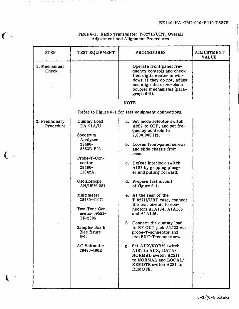
STEP
1. Mechanical Check
2. Preliminary Procedure
(
l
EE140-KA-OMI-010/E110 T827H
Table 6-1. Radio Transmitter T-827H/URT, Overall Adjustment and Alignment Procedures
TEST EQUIPMENT PROCEDURES
Operate front panel fre-quency controls and check that digits center in win-dows; if they do not, adjust and align the drive-chain coupler mechanisms (para-graph 6-9).
NOTE
Refer to Figure 6-1 for test equipment connections.
Dummy Load DA-91A/U
Spectrum Analyzer 28480-8553B-E03
Probe-T-Con-nector 28480-11042A.
Oscilloscope AN/USM-281
Multimeter 28480-410C
Two-Tone Gen-erator 09553-TF-2005
Sampler Box B (See figure 6-1)
AC Voltmeter 28480-400E
a. Set mode selector switch A2S2 to OFF, and set fre-quency controls to 2,000,000 Hz.
b. Loosen front-panel screws and slide chassis from case.
c. Defeat interlock switch A1S2 by gripping plung-er and pulling forward.
d. Prepare test circuit of figure 6-1.
e. At the rear of the T-827H/URT case, connect the test circuit to con-nectors A1A1J4, A1A1J5 and A1A1J6.
f. Connect the dummy load to RF OUT jack A1J23· via probe-T-connector and two BNC-T-connectors.
g. Set A UX/NORM switch A1S1 to AUX, DATA/ NORMAL switch A2Sll to NORMAL and LOCAL/ REMOTE switch A2S1 to REMOTE.
ADJUSTMENT VALUE
6-3/( 6-4 blank)
I I
;,
__
__
__
__
__
__
__
__
__
__
__
__
__
__
__
_ _
(
(
(
STEP
2. Preliminary Procedure (Cont.)
3. Power Supply Adjustment
I
EE 140-KA-OMI-010/E 110 T827H
Table 6-1. Radio Transmitter T-827H/URT, Overall Adjustment and Alignment Procedures (Continued)
TEST EQUIPMENT P ROCEDURES
WARNING
Dangerous voltages are present in underside of chassis when interlock is defeated. Exercise all necessary precautions to avoid electrical shock.
h. Apply power to T-827 H/ URT, set mode selector switch to STDBY, and allow a minimum of 5 minutes warm-up time before proceeding.
i. Set test circuit PPC ADJUST control fully clockwise.
j. Set CARRIER REINSERTION. switch A2A1Sl to CD.
CAUTION
Hand-guide main frame cable at rear of chassis over edge of case when rotating main frame to vertical position.
Digital Multimeter 89536-8800A/AA
a. Tilt the T-827H/URT chassis vertically to expose the underside.
b. Set mode selector switch A2S2 to LSB.
c. Connect digital multimeter between terminal A2E24 (+) and chassis (-).
CAUTION
If digital multimeter does not indicate +15 to +25 Vdc before keying, return mode selector switch to OFF, and troubleshoot the Power Supply Assembly A2A8 and Main Frame A2 before proceeding.
l I
ADJUSTMENT VALUE
6-7
EE 140-KA-OMI-010/E 110 T827H
STEP
3. Power Supply Adjustment (Cont.)
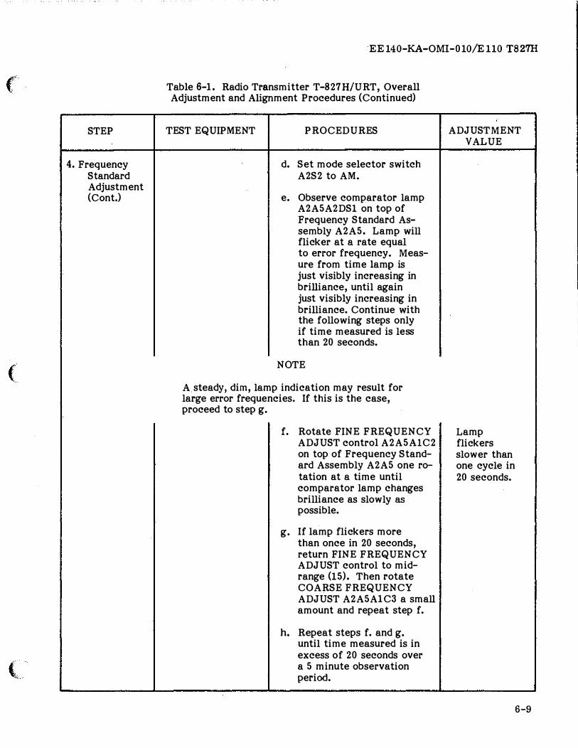
4. Frequency Standard Adjustment
..__ 6-8
Table 6-1. Radio Transmitter T-827H/U"RT, Overall Adjustment and Alignment Procedures (Continued)
TEST EQUIPMENT PROCEDURES
d. Set test circuit PTT KEY to ON and adjust A2A8R10 for 20.0 Vdc indication on digital multimeter.
e. Disconnect digital multi-meter and tilt chassis back to horizontal po-sition.
-------CAUTION -------
The 5 MHz oscillator circuit of Frequency Standard Assembly A2A5 must not be adjusted until it has been determined that the 5 MHz output frequency is in er-ror. Unnecessary adjustment will cause poor equipment operation that is not only difficult to correct, but which requires lengthy maintenance time.
Frequency Standard AN/URQ-10
a. Set mode selector switch A2S2 to STDBY, and 5 MHz OSC SOURCE switch A2A5-A2Sl to EXT (OVEN STBY). Allow at least a 3-day warmup period before -pro-ceeding with the final ad-justment. If imm.ediate adjustment is necessary, allow at least a 60-minute warm up period.
b. If not normally used, con-nect 5 MHz output of ex-ternal frequency standard AN/URQ-10 to EXT 5 MHz IN jack A1J25 on rear of T-827H/URT.
c. Set 5 MHz OSC SOURCE switch A2A5A2Sl on top of Frequency Standard Assembly A2A5 to INTI COMP.
,,
ADJUSTMENT VALUE
20.0 ±{).1 Vdc
">)
�)
(
(
t -'
STEP
4. Frequency Standard Adjustment (Cont.)
EE140-KA-OMI-010/E110 T827H
Table 6-1. Radio Transmitter T-827H/URT, Overall Adjustment and Alignment Procedures (Continued)
TEST EQUIPMENT PROCEDURES
d. Set mode selector switch A2S2 to AM.
e. Observe comparator lamp A2A5A2DS1 on top of Frequency Standard As-sembly A2A5. Lamp will flicker at a rate equal to error frequency. Meas-ure from time lamp is just visibly increasing in brilliance, until again just visibly increasing in brilliance. Continue with the following steps only if time measured is less than 20 seconds.
NOTE
A steady, dim, lamp indication may result for large error frequencies. If this is the case, proceed to step g.
f. Rotate FINE FREQUENCY ADJUST control A2A5Al C2 on top of Frequency Stand-ard Assembly A2A5 one ro-tation at a time until comparator lamp changes brilliance as slowly as
possible.
g. If lamp flickers more than once in 20 seconds, return FINE FREQUENCY ADJUST control to mid-range (15). Then rotate COARSE FREQUENCY ADJUST A2A5A 1C3 a small amount and repeat step f.
h. Repeat steps f. and g. until time measured is in excess of 20 seconds over a 5 minute observation period.
ADJUSTMENT VALUE
Lamp flickers slower than one cycle in 20 seconds.
I 6-9
EE 140-KA-OMI-010/E 110 T827H
STEP
4. Frequency Standard Adjustment (Cont.)
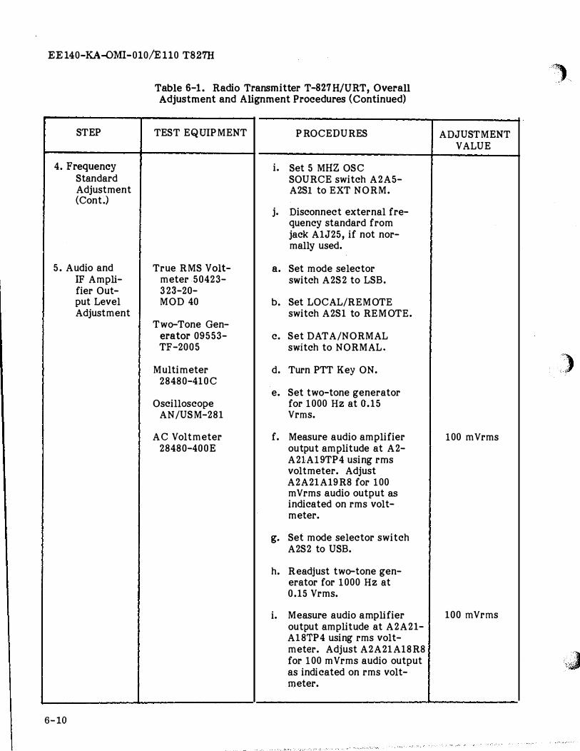
5. Audio and IF Ampli-fier Out-put Level Adjustment
6-10
Table 6-1. Radio Transmitter T-827H/URT, Overall Adjustment and Alignment Procedures (Continued)
TEST EQUIPMENT
True RMS Volt-meter 50423-323-20-MOD 40
Two-Tone Gen-erator 09553-TF-2005
Multimeter 28480-410C
Oscilloscope AN/USM-281
AC Voltmeter 28480-400E
,,_
PROCEDURES
i. Set 5 MHZ OSC SOURCE switch A2A5-A2Sl to EXT NORM.
j. Disconnect external fre-quency standard from jack A1J25, if not nor-mally used.
a. Set mode selector switch A2S2 to LSB.
b. Set LOCAL/REMOTE switch A2Sl to REMOTE.
c. Set DATA/NORMAL switch to NORMAL.
d. Turn PTT Key ON.
e. Set two-tone generator for 1000 Hz at 0.15 Vrms.
f. Measure audio amplifier output amplitude at A2-A21Al9TP4 using rms voltmeter. Adjust A2A21A19R8 for 100 mVrms audio output as
indicated on rms volt-meter.
g. Set mode selector switch A2S2 to USB.
h. Readjust two-tone gen-erator for 1000 Hz at 0.15 Vrms.
i. Measure audio amplifier output amplitude at A2A21-A18TP4 using rms volt-meter. Adjust A2A21Al8R8 for 100 mVrms audio output as indicated on rms volt-meter.
,'�)
ADJUSTMENT VALUE
'','), >"
100 mVrms
100 mVrms
�;J
(
STEP
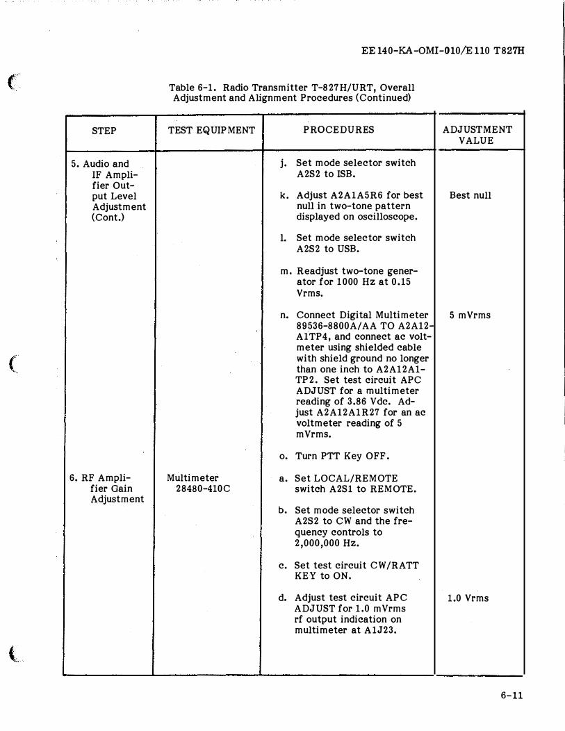
5. Audio and IF Ampli-fier Out-put Level Adjustment (Cont.)
(
6. RF Ampli-fier Gain Adjustment
(
EE 140-KA-OMI-010/E 110 T827H
Table 6-1. Radio Transmitter T-827H/URT, Overall Adjustment and Alignment Procedures (Continued)
TEST EQUIPMENT
Multimeter 28480-410C
PROCEDURES
j. Set mode selector switch A2S2 to ISB.
k. Adjust A2AlA5R6 for best null in two-tone pattern displayed on oscilloscope.
1. Set mode selector switch A2S2 to USB.
m. Readjust two-tone gener-ator for 1000 Hz at 0.15 Vrms.
n. Connect Digital Multimeter 89536-8800A/ AA TO A2Al2-Al TP4, and connect ac volt-meter using shielded cable with shield ground no longer than one inch to A2A12A1-TP2. Set test circuit APC ADJUST for a multimeter reading of 3.86 Vdc. Ad-just A2Al2A1R27 for an ac voltmeter reading of 5 mVrms.
o. Turn PTT Key OFF.
a. Set LOCAL/REMOTE switch A2Sl to REMOTE.
b. Set mode selector switch A2S2 to CW and the fre-quency controls to 2,000,000 Hz.
c. Set test circuit CW /RATT KEY to ON.
d. Adjust test circuit APC ADJUST for 1.0 mVrms rf output indication on multimeter at A1J23.
ADJUSTMENT VALUE
Best null
5 mVrms
1.0 Vrms
6-11
EE 140-KA-OMI- 010/E 110 T827H
STEP
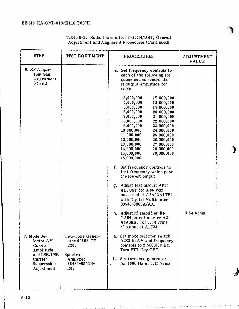
6. RF Ampli-fier Gain Adjustment (Cont.)
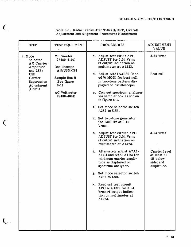
7. Mode Se-lector AM Carrier Amplitude and LSB/USB Carrier Suppression Adjustment
6-12
Table 6-1. Radio Transmitter T-827H/URT, Overall Adjustment and Alignment Procedures (Continued)
TEST EQUIPMENT PROCEDURES
e. Set frequency controls to each of the following fre-quencies and record the rf output amplitude for each:
3,000,000 17,000,000 4,000,000 18,000,000 5,000,000 19,000.000 6,000,000 20,000,000 7,000,000 21,000,000 8,000,000 22,000,000 9,000,000 23,000,000
10,000,000 24,000,000 11,000,000 25,000,000 12,000,000 26,000,000 13,000,000 27,000,000 14,000,000 28,000,000 15,000,000 29,000,000 16,000,000
f. Set fr�quency controls to that frequency which gave the lowest output.
g. Adjust test circuit APC ADJUST for 3.86 Vdc measured at A2Al2Al TP4 with Digital Multimeter 89536-8800A/ AA.
h. Adjust rf amplifier RF GAIN potentiometer A2-A4A38R6 for 3.54 Vrms rf output at A1J23.
Two-Tone Gener- a. Set mode selector switch ator 09553-TF- A2S2 to AM and frequency 2205 controls to 2,500,000 Hz.
Turn PTT Key OFF. Spectrum
Analyzer b. Set two-tone generator 28480-85538- for 1000 Hz at 0.15 Vrms. E03
')
ADJUSTMENT VALUE
)
3.54 Vrms
�J
('
STEP
7. Mode Selector AM Carrier Amplitude and LSB/ USB Carrier Suppression Adjustment (Cont.)
(
{I
EE 140-KA-OMI-010/E 110 T827H
Table 6-1. Radio Transmitter T-827H/URT, Overall Adjustment and Alignment Procedures (Continued)
TEST EQUIPMENT
Multimeter 28480-410C
Oscilloscope AN/USM-281
Sample Box B (See figure 6-1)
AC Voltmeter 28480-400E
PROCEDURES
c. Adjust test ciruit APC ADJUST for 3.54 Vrms rf output indication on multimeter at A1J23.
d. Adjust A2A1A4R39 (label-ed % MOD) for best null in two-tone pattern dis-played on oscilloscope.
e. Connect spectrum analyzer via sampler box as shown in figure 6-1.
f. Set mode selector switch A2S2 to USB.
g. Set two-tone generator for 1 300 Hz at 0.15 Vrms.
h. Adjust test circuit APC ADJUST for 3.54 Vrms rf output indication on multimeter at A1J23.
i. Alternately adjust A2A1-A1C4 and A2A1A1R3 for minimum carrier ampli-tude as displayed on spectrum analyzer.
j. Set mode selector switch A2S2 to LSB.
k. Readjust test circuit APC ADJUST for 3.54 Vrms rf output indica-tion on multimeter at AlJ23.
ADJUSTMENT VALUE
3.54 Vrms
Best null
3.54 Vrms
Carrier level at least 50 dB below sideband amplitude.
6-13
EE140-KA-OMI-010/E110 T827H
STEP
7. Mode Selector AM Carrier Amplitude and LSB/ USB Carrier Suppression Adjustment (Cont.)
6-14
Table 6-1. Radio Transmitter T-827H/URT, Overall Adjustment and Alignment Procedures (Continued)
TEST EQUIPMENT PROCEDURES
1. Alternately adjust A2-AlA2C4 and A2AlA2R3 for minimum carrier amplitude as displayed on spectrum analyzer.
m. Set mode selector switch to STDBY and disconnect all test equipment. Slide chassis into case and secure front panel screws.
-
,,_
ADJUSTMENT VALUE
Carrier level at least 50
dB below sideband amplitude.
)
,.).: ?
(
STEP
1. Preliminary Procedure
(
2. Carrier Maximi-zation for USB Operation
l
EE140-KA-OMI-010/El10 T827H
Table 6-2. Mode Selector Assembly A2A1, Adjustment and Alignment Procedures
TEST EQUIPMENT PROCEDURES
Amplifier /Mode a. Remove cover from Selector Test Mode Selector As-Fixture TS- sembly A2A1, and 3670/WRC-1 connect test equip-
ment as shown in Oscilloscope Figure 6-2.
AN/USM-281 b. Adjust test fixture
Spectrum for 20 Vdc indica-Analyzer tion on digital 28480- multimeter, and set 8553B-E03 test fixture con-
trols to test T-Digital Multi- 827H/URT Mode Se-
meter 89536- lector Assembly 8800A/AA in USB transmitting
mode (no modu-RF Signal Gen- lation).
erator 28480-8640B-001-003 c. Set rf signal gener-
ator for 500 kHz at an output level o f 175 mVrms.
d. Set CARRIER REIN-SERTION switch on Mode Selector As-sembly toeD.
RF Signal Gen- a. Connect oscillo-erator 28480- scope to A2A1A4E21. 8640B-001-003 b. Adjust A2A1A4T1 for
maximum 500 kHz Oscilloscope amplitude indica-
AN/USM-281 tion on oscillo-scope.
Amplifier /Mode Selector Test Fixture TS-
3670/WRC-1
-------
ADJUSTMENT VALUE
20 ±().1 Vdc
175 ±5 mVrms
2.5 V P-P
6-15
I
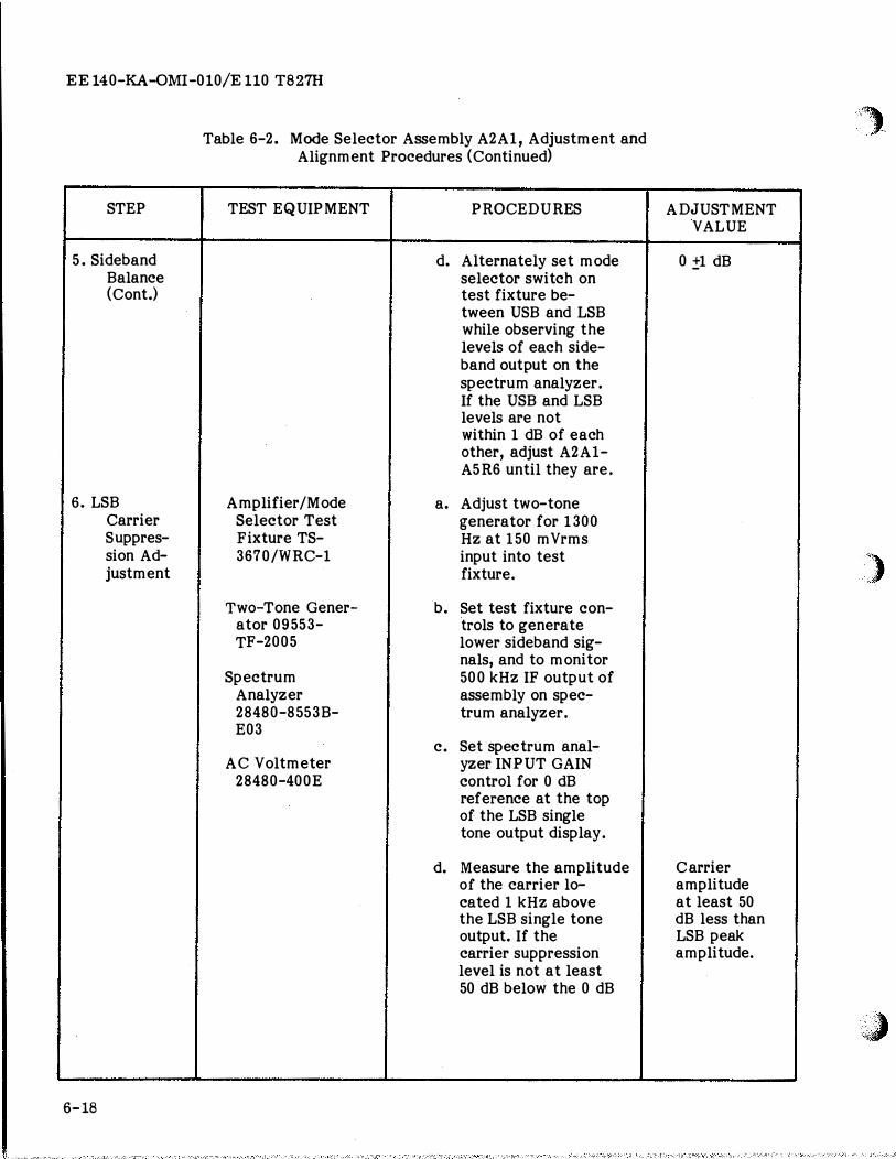
EE140-KA-0MI-010/E110 T827H
OSCIL LOSCOPE AN/USM-281
AC VOLTMETER 28480-400E
R F SIGNAL GENERATOR 28480-86408-001-03
TWO-TONE GENERATOR 09553-TF-2005
6-16
AMPLIFIER / MODE SELECTOR ASSEMBLY
A2AI
I �A4E21
1-- f<>A4E6 J �A4E3 I r -- , r--, I ..1 PI P2
I L J7_J L �8_ j I
� I I L_ AUDIO OUT
AMPLIFIER / MODE SELECTOR TEST
FIXTURE TS-3670/WRC-1
SPECTR UM
4>- 500KHZ 500KHZ �> ANALYZER
ANAL YZER 28480-85538-STD E03
�>-DIGITAL
AUDIO IN """
20VD C
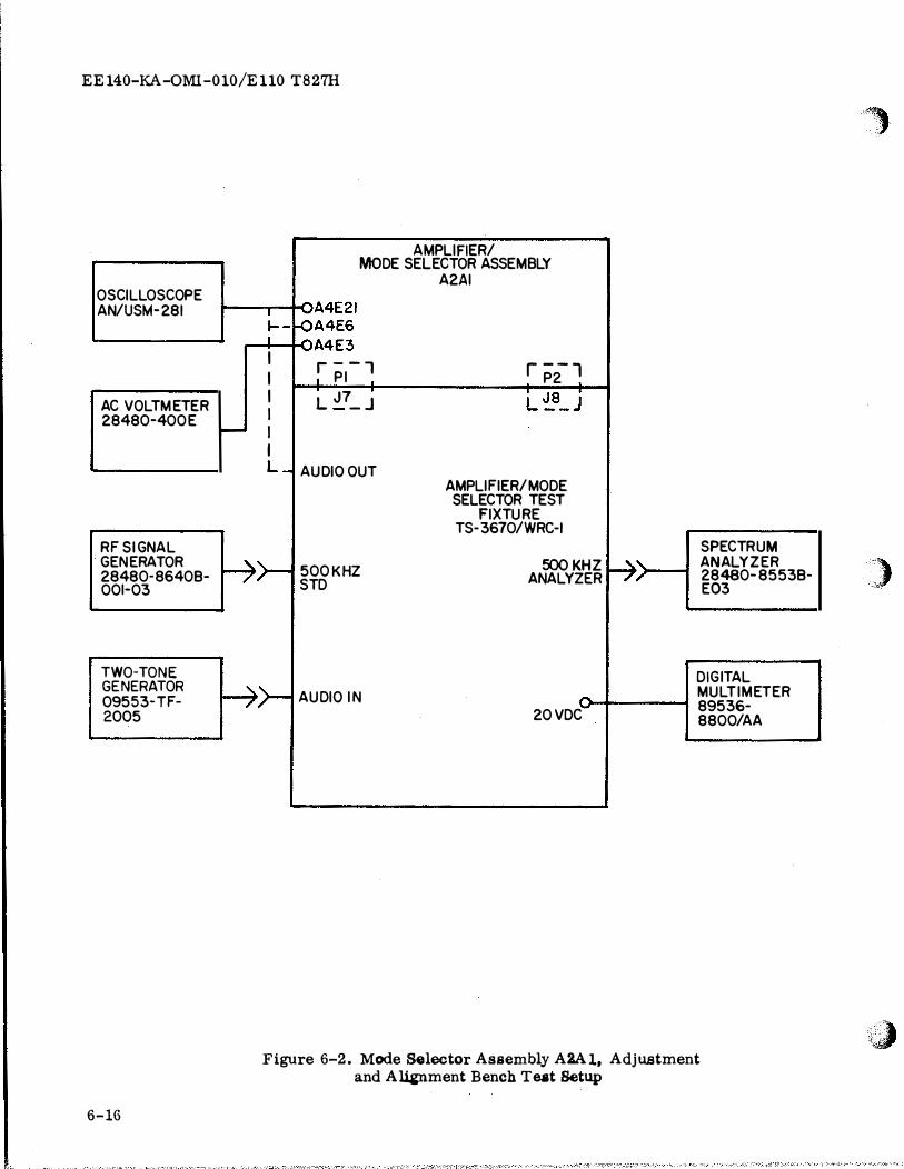
Figure 6-2. Mode Selector Assembly A2Al, Adjustment and A14Ptment Bench Teat Setup
MULTI METER 89536-8800/AA
,.,
)
'�
(
STEP
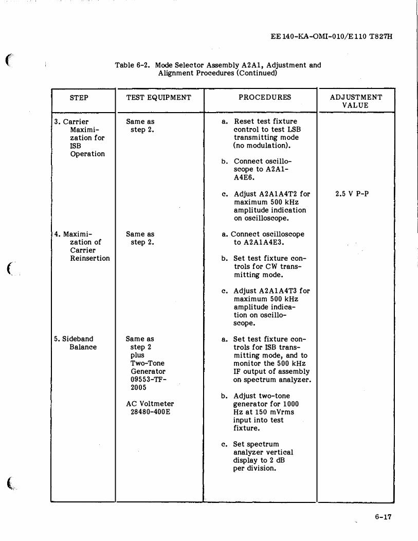
3. Carrier Maximi-zation for ISB Operation
4. Maximi-zation of Carrier Reinsertion
( '
5. Sideband Balance
(
EE 140-K.A-OMI-010/E 110 T827H
Table 6-2. Mode Selector Assembly A2Al, Adjustment and Alignment Procedures (Continued)
TEST EQUIPMENT PROCEDURES
Same as a. Reset test fixture step 2. control to test LSB
transmitting mode (no modulation).
b. Connect oscillo-scope to A2Al-A4E6.
c. Adjust A2AlA4T2 for maximum 500 kHz amplitude indication on oscilloscope.
Same as a. Connect oscilloscope step 2. to A2AlA4E3.
b. Set test fixture con-trols for CW trans-mitting mode.
c. Adjust A2AlA4T3 for maximum 500 kHz amplitude indica-tion on oscillo-scope.
Same as a. Set test fixture con-step 2 trols for ISB trans-plus mitting mode, and to Two-Tone monitor the 500 kHz Generator IF output of assembly 09553-TF- on spectrum analyzer. 2005
b. Adjust two-tone AC Voltmeter generator for 1000
28480-400E Hz at 150 mVrms input into test fixture.
c. Set spectrum analyzer vertical display to 2 dB per division.
ADJUSTMENT VALUE
2.5 V P-P
6-17
EE 140-KA-QMI-010/E 110 T827H
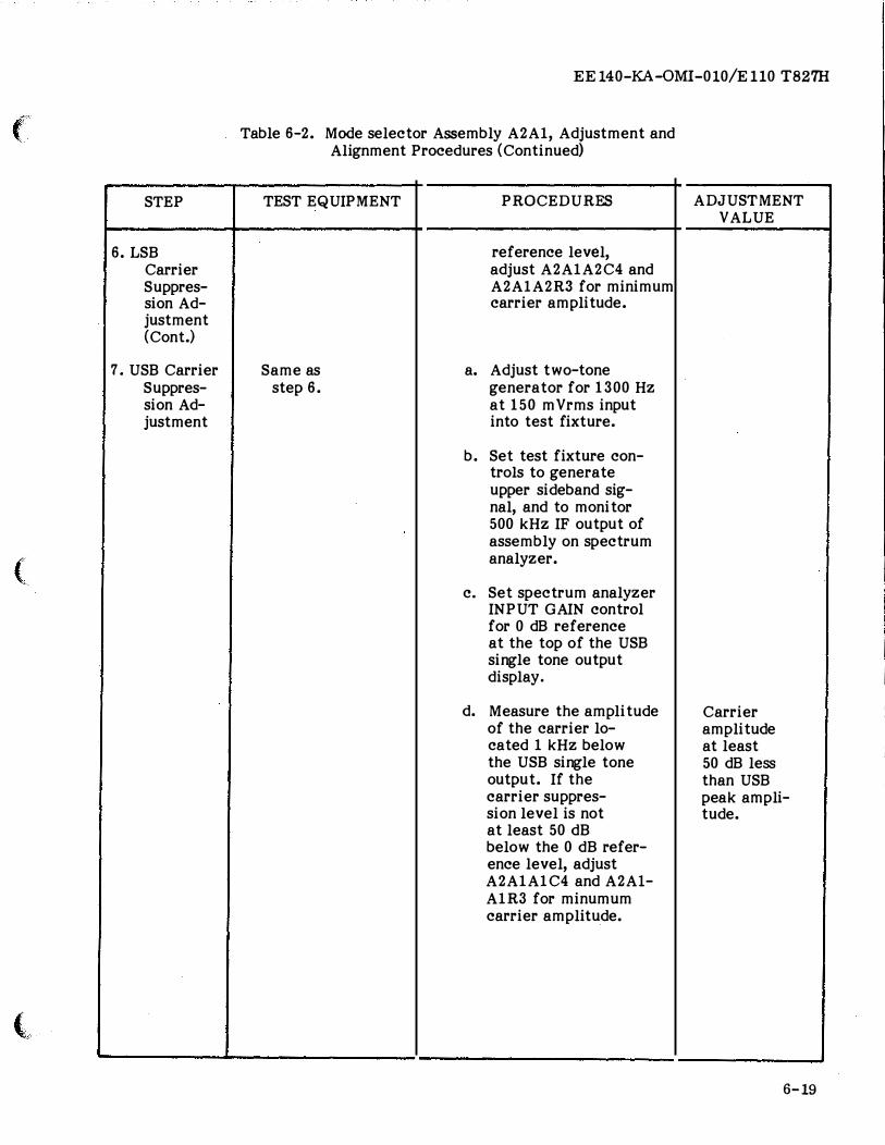
STEP
5. Sideband Balance (Cont.)
6. LSB Carrier Suppres-sion Ad-justment
6-18
Table 6-2. Mode Selector Assembly A2A1, Adjustment and Alignment Procedures (Continued)
TEST EQUIPMENT PROCEDURES
d. Alternately set mode selector switch on test fixture be-tween USB and LSB while observing the levels of each side-band output on the spectrum analyzer. If the USB and LSB levels are not within 1 dB of each other, adjust A2A1-A5 R6 until they are.
Amplifier/Mode a. Adjust two-tone Selector Test generator for 1300 Fixture TS- Hz at 150 mVrms 3670/WRC-1 input into test
fixture.
Two-Tone Gener- b. Set test fixture con-ator 09553- trols to generate TF-2005 lower sideband sig-
nals, and to monitor Spectrum 500 kHz IF output of
Analyzer assembly on spec-28480-8553B- trum analyzer. E03
c. Set spectrum anal-AC Voltmeter yzer INPUT GAIN
28480-400E control for 0 dB reference at the top of the LSB single tone output display.
d. Measure the amplitude of the carrier lo-cated 1 kHz above the LSB single tone output. If the carrier suppression level is not at least 50 dB below the 0 dB
ADJUSTMENT VALUE
0 ±1 dB
Carrier amplitude at least 50 dB less than LSB peak amplitude.
�,, ' �' . "
,;� �
)
·� <�
(
STEP
6. LSB Carrier Suppres-sion Ad-justment (Cont.)
7. USB Carrier Suppres-sion Ad-justment
(
(
EE140-KA-OMI-010/Ell0 T827H
Table 6-2. Mode selector Assembly A2A1, Adjustment and Alignment Procedures (Continued)
TEST EQUIPMENT PROCEDURES
reference level, adjust A2A1A2C4 and A2A1A2R3 for minimum carrier amplitude.
Same as a. Adjust two-tone step 6. generator for 1300 Hz
at 150 mVrms input into test fixture.
b. Set test fixture con-trois to generate upper sideband sig-nal, and to monitor 500 kHz IF output of assembly on spectrum analyzer.
c. Set spectrum analyzer INPUT GAIN control for 0 dB reference at the top of the USB single tone output display.
d. Measure the amplitude of the carrier lo-cated 1 kHz below the USB single tone output. If the carrier suppres-sion level is not at least 50 dB below the 0 dB refer-ence level, adjust A2A1A1C4 and A2Al-A1R3 for minumum carrier amplitude.
ADJUSTMENT VALUE
Carrier amplitude at least 50 dB less than USB peak ampli-tude.
6-19
EE 140-KA-OMI-010/E 110 T827H
STEP
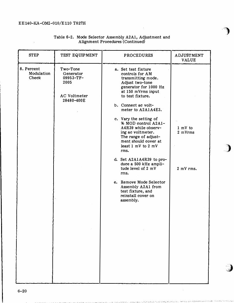
8. Percent Modulation Check
6-20
Table 6-2. Mode Selector Assembly A2A1, Adjustment and Alignment Procedures (Continued)
TEST EQUIPMENT PROCEDURES
Two-Tone a. Set test fixture Generator controls for AM 09953-TF- transmitting mode. 2005 Adjust two-tone
generator for 1000 Hz at 150 mVrms input
AC Voltmeter to test fixture. 28480-400E
b. Connect ac volt-meter to A2A1A4E3.
c. Vary the setting of 96 MOD control A2A1-A4R39 while observ-ing ac voltmeter. The range of adjust-ment should cover at least 1 mV to 2 mV rms.
d. Set A2A1A4R39 to pro-duce a 500 kHz ampli-tude level of 2 m V rms.
e. Remove Mode Selector Assembly A2A1 from test fixture, and reinstall cover on
I assembly.
-�
ADJUSTMENT VALUE
1 mV to 2 mVrms
2 mV rms.
'")
)
' '·Y:I
(
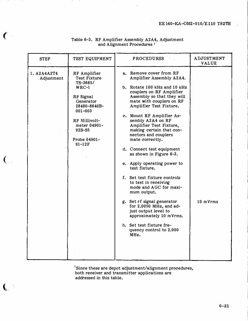
STEP
l. A2A4A2T4 Adjustment
(
(
EE 140-KA-OMI-010/E 110 T827H
Table 6-3. RF Amplifier Assembly A2A4, Adjustment and Alignment Procedures 1
TEST EQUIPMENT
RF Amplifier Test Fixture TS-3685/ WRC-1
RF Signal Generator 28480-86408-001-003
RF Millivolt-meter 04901-92B-S5
Probe 04901-91-12F
PROCEDURES
a. Remove cover from RF Amplifier Assembly A2A4.
b. Rotate 100 kHz and 10 kHz couplers on RF Amplifier Assembly so that they will mate with couplers on RF Amplifier Test Fixture.
c. Mount RF Amplifier As-sembly A2A4 on RF Amplifier Test Fixture, making certain that con-nectors and couplers mate correctly.
d. Connect test equipment as shown in Figure 6-3.
e. Apply operating power to test fixture.
f. Set test fixture controls to test in receiving mode and AGC for maxi-mum output.
g. Set rf signal generator for 2.0050 MHz, and ad-just output level to approximately 10 mVrms.
h. Set test fixture fre-quency control to 2.000 MHz.
1 Since these are depot adjustment/alignment procedures, both receiver and transmitter applications are addressed in this table.
ADJUSTMENT VALUE
10 mVrms
6-21
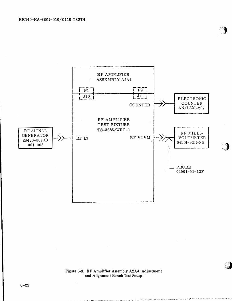
EE 140-KA-OMI-010/E 110 T827H
RF SIGNAL
GENERATOR
28480-BG.fOB-
001-003
6-22
r-- .... _,
I P1 I
j_ J_!O_J
�H RFIN
RF AMPLIFIER
ASSEMBLY A2A4
RF AMPLIFIER
TEST FIXTURE
r----.
I P2 I
L �1.2-J
COUNTER ��
TS-3685/WRC-1 �' RF VTVM
/
Figure 6-3. RF Amplifier Assembly A2A4, Adjustment and Alignment Bench Test Setup
ELECTRONIC
COUNTER
AN/USM-207
RF MILLI
VOLTMETER
0490l-92B-S5
PROBE
04901-91-12F
r,,_
)
i�
(
(
�' ';�
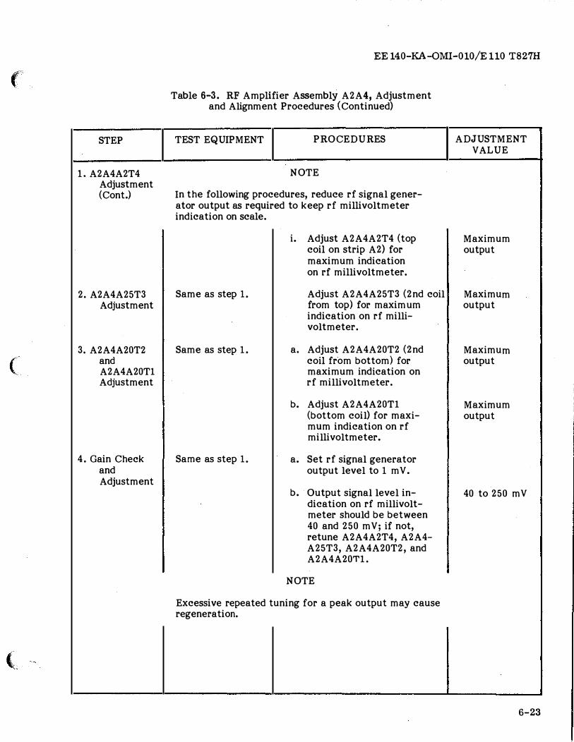
STEP
1. A2A4A2T4 Adjustment (Cont.)
2. A2A4A25T3 Adjustment
3. A2A4A20T2 and A2A4A20Tl Adjustment
4. Gain Check and Adjustment
EE 140-KA-OMI-010/E 110 T827H
Table 6-3. RF Amplifier Assembly A2A4, Adjustment and Alignment Procedures (Continued)
TEST EQUIPMENT PROCEDURES
NOTE
In the following procedures, reduce rf signal gener-ator output as required to keep rf millivoltmeter indication on scale.
Same as step 1.
Same as step 1.
Same as step 1.
i. Adjust A2A4A2T4 (top coil on strip A2) for maximum indication on rf millivoltmeter.
Adjust A2A4A25T3 (2nd coil from top) for maxim urn indication on rf milli-voltmeter.
a. Adjust A2A4A20T2 (2nd coil from bottom} for maximum indication on rf millivoltmeter.
b. Adjust A2A4A20Tl (bottom coil) for maxi-mum indication on rf millivoltmeter.
a. Set rf signal generator output level to 1 mV.
b. Output signal level in-dication on rf millivolt-meter should be between 40 and 250 mV; if not, retune A2A4A2T4, A2A4-A25T3, A2A4A20T2, and A2A4A20Tl.
NOTE
Excessive repeated tuning for a peak output may cause regeneration.
ADJUSTMENT VALUE
Maximum output
Maximum output
Maximum output
Maximum output
'
40 to 250 mV
I
6-23
EE 140-KA-OMI-010/E 110 T827H
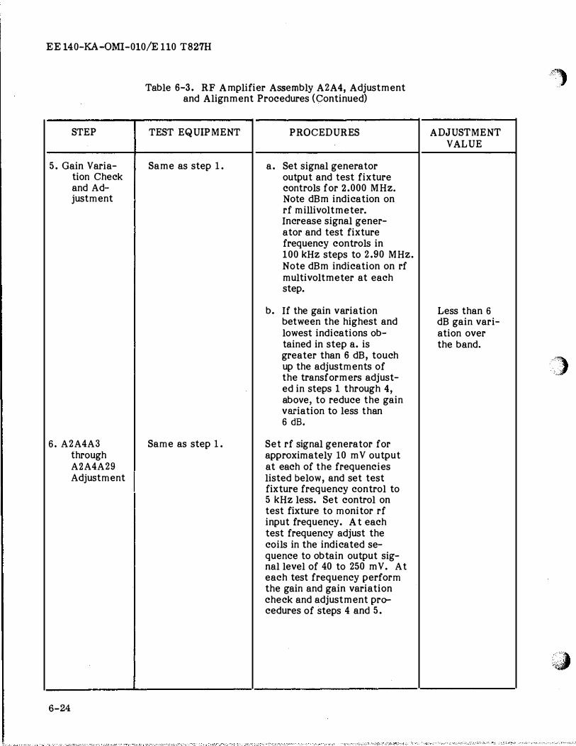
STEP
5. Gain Varia-tion Check and Ad-justment
6. A2A4A3 through A2A4A29 Adjustment
6-24
Table 6-3. RF Amplifier Assembly A2A4, Adjustment and Alignment Procedures (Continued)
TEST EQUIPMENT PROCEDURES
Same as step 1. a. Set signal generator output and test fixture controls for 2.000 MHz. Note dBm indication on rf millivoltmeter. Increase signal gener-ator and test fixture frequency controls in 100 kHz steps to 2.90 MHz. Note dBm indication on rf multivoltmeter at each step.
b. If the gain variation between the highest and lowest indications ob-tained in step a. is greater than 6 dB, touch up the adjustments of the transformers adjust-ed in steps 1 through 4, above, to reduce the gain variation to less than 6 dB.
Same as step 1. Set rf signal generator for approximately 10 mV output at each of the frequencies listed below, and set test fixture frequency control to 5 kHz less. Set control on test fixture to monitor rf input frequency. At each test frequency adjust the coils in the indicated se-quence to obtain output sig-nal level of 40 to 250 mV. At each test frequency perform the gain and gain variation check and adjustment pro-cedures of steps 4 and 5.
--�-
�,
ADJUSTMENT VALUE
Less than 6
dB gain vari-ation over the band.
)
'�
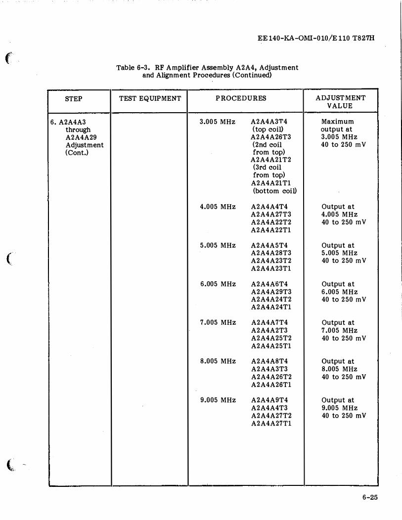
(
STEP
6. A2A4A3 through A2A4A29 Adjustment (Cont.)
(
( -
EE 140-KA-OMI-010/E 110 T827H
Table 6-3. RF Amplifier Assembly A2A4, Adjustment and Alignment Procedures (Continued)
TEST EQUIPMENT PROCEDURES
3.005 MHz A2A4A3T4 (top coil)
A2A4A26T3 (2nd coil from top)
A2A4A21T2 (3rd coil from top)
A2A4A21Tl (bottom coil)
4.005 MHz A2A4A4T4 A2A4A27T3 A2A4A22T2 A2A4A22Tl
5.005 MHz A2A4A5T4 A2A4A28T3 A2A4A23T2 A2A4A23Tl
6.005 MHz A2A4A6T4 A2A4A29T3 A2A4A24T2 A2A4A24Tl
7.005 MHz A2A4A7T4 A2A4A2T3 A2A4A25T2 A2A4A25Tl
8.005 MHz A2A4A8T4 A2A4A3T3 A2A4A26T2 A2A4A26Tl
9.005 MHz A2A4A9T4 A2A4A4T3 A2A4A27T2 A2A4A27Tl
ADJUSTMENT VALUE
Maximum output at 3.005 MHz 40 to 250 mY
Output at 4.005 MHz 40 to 250 mY
Output at 5.005 MHz 40 to 250 mY
Output at 6.005 MHz 40 to 250 mY
Output at 7.005 MHz 40 to 250 mY
Output at 8.005 MHz 40 to 250 mV
Output at 9.005 MHz 40 to 250 mV
6-25
i
EE 140-KA-QMI-010/E 110 T827H
STEP I
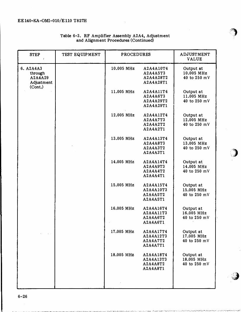
6. A2A4A3 through A2A4A29 Adjustment (Cont.)
6-26
Table 6-3. RF Amplifier Assembly A2A4, Adjustment and Alignment Procedures (Continued)
TEST EQUIPMENT PROCEDURES
10.005 MHz A2A4A10T4 A2A4A5T3 A2A4A28T2 A2A4A28T1
11.005 MHz A2A4A11T4 A2A4A6T3 A2A4A29T2 A2A4A29T1
12.005 MHz A2A4A12T4 A2A4A7T3 A2A4A2T2 A2A4A2T1
13.005 MHz A2A4A13T4 A2A4A8T3 A2A4A3T2 A2A4A3T1
14.005 MHz A2A4A14T4 A2A4A9T3 A2A4A4T2 A2A4A4T1
15.005 MHz A2A4A15T4 A2A4A10T3 A2A4A5T2 A2A4A5T1
16.005 MHz A2A4A16T4 A2A4A11T3 A2A4A6T2 A2A4A6T1
17.005 MHz A2A4A17T4 A2A4A12T3 A2A4A7T2 A2A4A7Tl
18.005 MHZ A2A4A18T4 A2A4Al3T3 A2A4A8T2 A2A4A8Tl
ADJUSTMENT VALUE
Output at 10.005 MHz 40 to 250 mY
Output at 11.005 MHz 40 to 250 mY
Output at 12.005 MHz 40 to 250 mY
Output at 13.005 MHz 40 to 250 mY
Output at 14.005 MHz 40 to 250 mY
Output at 15.005 MHz 40 to 250 mY
Output at 16.005 MHz 40 to 250 mY
Output at 17.005 MHz 40 to 250 mY
Output at 18.005 MHz 40 to 250 mY
f., ..
M , '
,�)
;1tJ
(
(
I ''"'
STEP
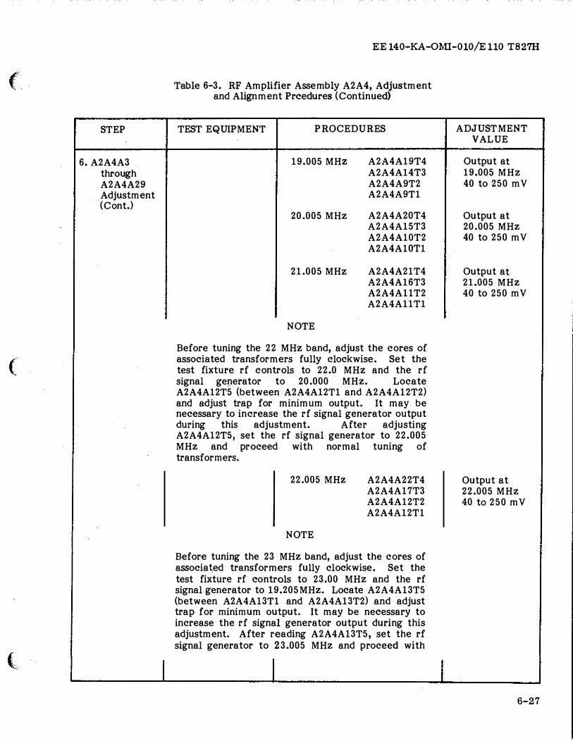
6.A2A4A3 through A2A4A29 Adjustment (Cont.)
I
EE 140-KA-OMI-010/E 110 T827H
Table 6-3. RF Amplifier Assembly A2A4, Adjustment and Alignment Prcedures (Continued)
TEST EQUIPMENT P ROCEDURES
19.005 MHZ
20.005 MHz
21.005 MHz
NOTE
A2A4A19T4 A2A4A14T3 A2A4A9T2 A2A4A9T1
A2A4A20T4 A2A4A15T3 A2A4A10T2 A2A4AlOT1
A2A4A21T4 A2A4Al6T3 A2A4AllT2 A2A4Al1T1
Before tuning the 22 MHz band, adjust the cores of associated transformers fully clockwise. Set the test fixture rf controls to 22.0 MHz and the rf signal generator to 20.000 MHz. Locate A2A4A12T5 (between A2A4A12Tl and A2A4Al2T2) and adjust trap for minimum output. It may be necessary to increase the rf signal generator output during this adjustment. After adjusting A2A4A12T5, set the rf signal generator to 22.005 MHz and proceed with normal tuning of transformers.
22.005 MHz
NOTE
A2A4A22T4 A2A4Al7T3 A2A4A12T2 A2A4A12Tl
Before tuning the 23 MHz band, adjust the cores of associated transformers fully clockwise. Set the test fixture rf controls to 23.00 MHz and the rf signal generator to 19.205MHz. Locate A2A4Al3T5 (between A2A4A13Tl and A2A4A13T2) and adjust trap for minimum output. It may be necessary to increase the rf signal generator output during this adjustment. After reading A2A4Al3T5, set the rf signal generator to 23.005 MHz and proceed with
l I
ADJUSTMENT VALUE
Output at 19.005 MHz 40 to 250 mY
Output at 20.005 MHz 40 to 250 mY
Output at 21.005 MHz 40 to 250 mY
Output at 22.005 MHz 40 to 250 mY
6-27
EE140-KA-OMI-010/Ell0 T827H
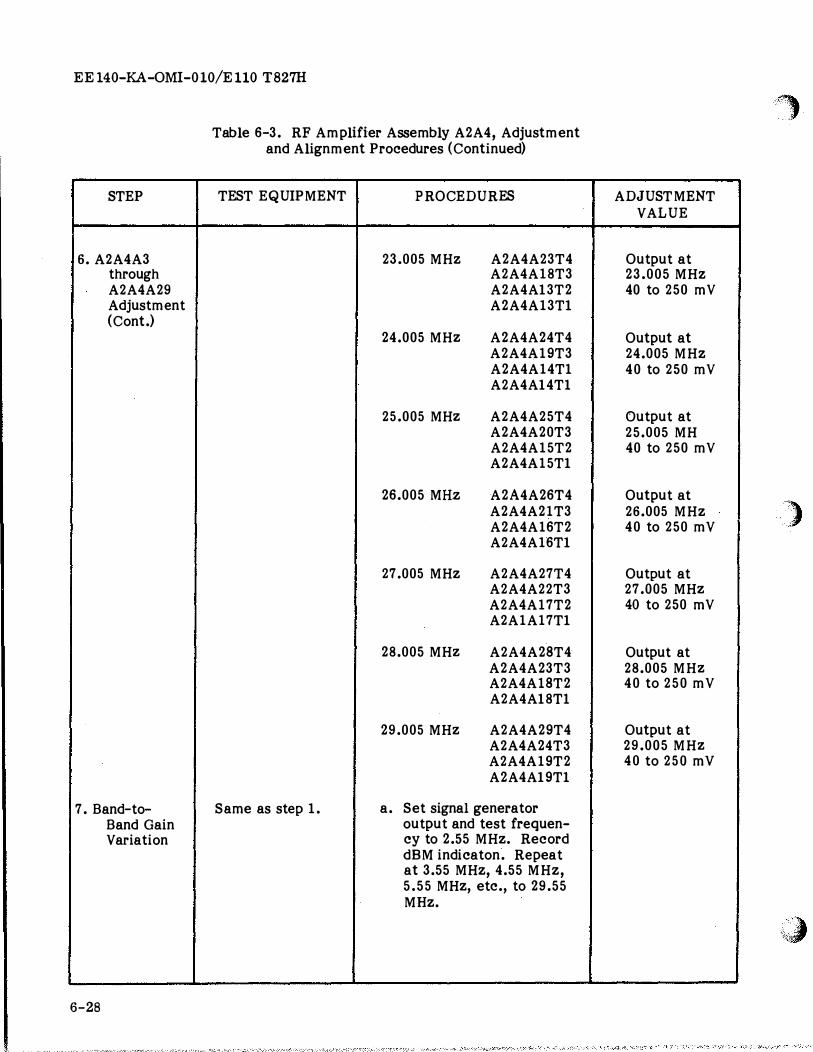
STEP
6. A2A4A3 through A2A4A29 Adjustment (Cont.)
7. Band-to-Band Gain Variation
I
6-28
Table 6-3. RF Amplifier Assembly A2A4, Adjustment and Alignment Procedures (Continued)
TEST EQUIPMENT PROCEDURES
23.005 MHz A2A4A23T4 A2A4A18T3 A2A4Al3T2 A2A4A13Tl
24.005 MHZ A2A4A24T4 A2A4A19T3 A2A4A14Tl A2A4Al4Tl
25.005 MHZ A2A4A25T4 A2A4A20T3 A2A4A15T2 A2A4A15Tl
26.005 MHz A2A4A26T4 A2A4A21T3 A2A4A16T2 A2A4A16Tl
27.005 MHz A2A4A27T4 A2A4A22T3 A2A4A17T2 A2A1A17Tl
28.005 MHZ A2A4A28T4 A2A4A23T3 A2A4A18T2 A2A4Al8Tl
29.005 MHZ A2A4A29T4 A2A4A24T3 A2A4A19T2 A2A4Al9Tl
S ame as step 1. a. S et signal generator output and test frequen-cy to 2.55 MHz. Record dBM indicaton. Repeat at 3.55 MHz, 4.55 MHz, 5.55 MHz, etc., to 29.55 MHz.
------------------ ----
''·'.·· . . 1
ADJUSTMENT VALUE
Output at 23.005 MHz 40 to 250 mY
Output at 24.005 MHz 40 to 250 mY
Output at 25.005 MH 40 to 250 mY
Output at 26.005 MHz 40 to 250 mY )
Output at 27.005 MHZ 40 to 250 mY
Output at 28.005 MHZ 40 to 250 mY
Output at 29.005 MHZ 40 to 250 mY
�a
(
STEP
7. Band-to-Band Gain Variation (Cont.)
8. Overall Gain Adjust-ment
(
(
EE140-KA-OMI-010/E110 T827H
Table 6-3. RF Amplifier Assembly A2A4, Adjustment and Alignment Procedures (Continued)
TEST EQUIPMENT PROCEDURES
b. If the gain variation between the highest and lowest readings obtained in step a. exceeds 15 dB, readjust the high gain band by turning T4 to reduce the band-to-band variation to less than 15 dB.
Same as step 1. a. Set test fixture controls for transmit mode.
b. Set rf amplifier test fixture rf frequency con-trois for 22.000 MHz.
c. Set signal generator for 22.005 MHz and adjust output level to obtain 3.5 mVrms at A2A4A38-TP1 using the rf milli-voltmeter to measure the level.
d. Connect rf millivolt-meter to A2A4TP3. (Ground meter probe at A2A4TP4.)
e. Adjust A2A4A38R6.
f. Disconnect test equip-ment.
ADJUSTMENT VALUE
Less than 15 dB variation
2.5 Vrms
6-29
EE140-KA-OMI-010/E 110 T827H
STEP
1. Initial Test Setup
2. Frequency Check
3. Fine Frequency Adjustment
6-30
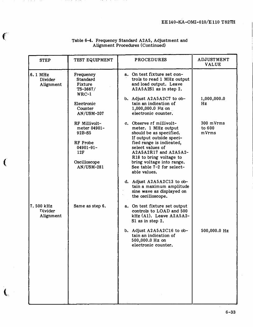
Table 6-4. Frequency Standard A2A5, Adjustment and Alignment Procedures
TEST EQUIPMENT
Frequency Standard Test Fixture TS-3667 /WRC-1
Frequency Standard Test Fixture TS-3667 /WRC-1
Electronic Counter AN/USM-207
Same as step 2.
PROCEDURES
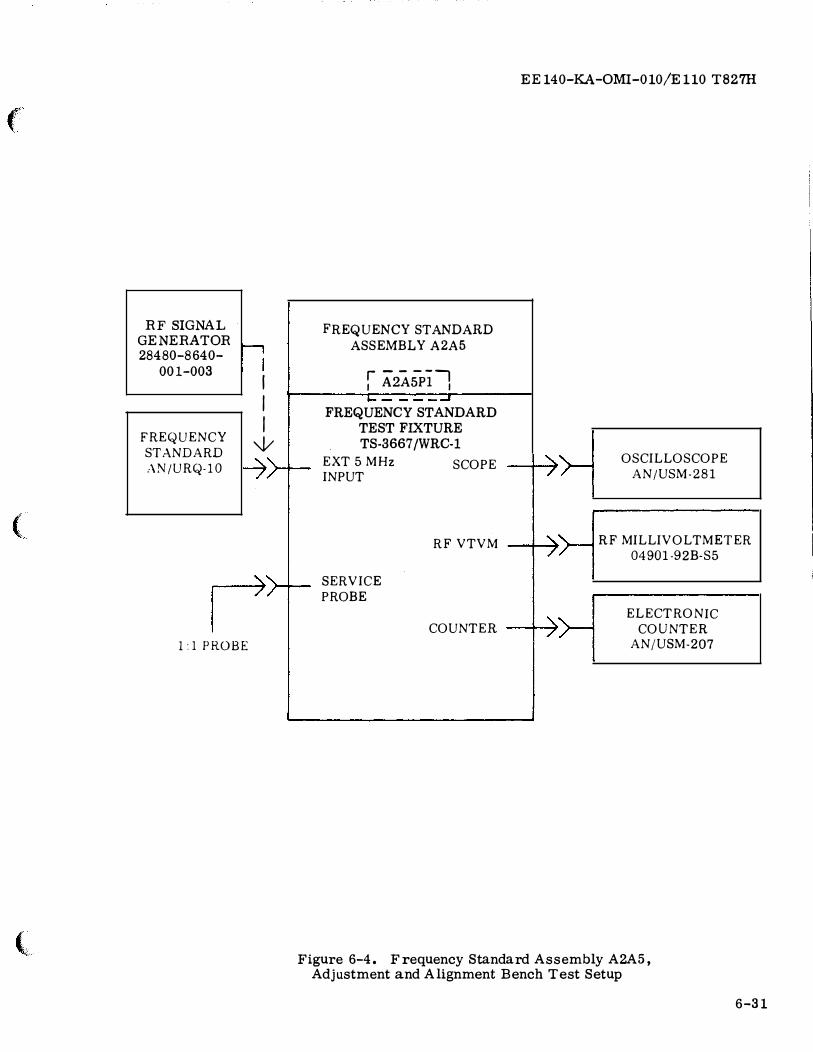
a. Connect Frequency Standard and test equipment as shown in Figure 6-4.
b. Set 5 MHz OSC SOURCE switch A2A5A2S1 to INTI COMP position.
c. Apply power to test fix-ture and allow a 96-hour (minimum) warmup.
Set time base on counter for a 10-second gate. On test fixture set output controls to LOAD and INT 5 MHz. Counter shall indicate 4,999,999.8 Hz to 5,000,000.2 Hz. If indica-tion is within limits, pro-ceed to step 5, otherwise proceed to step 3.
a. Adjust FINE FREQUENCY ADJUST control A2A5A1C2 with a screwdriver until an indication of 5,000,000.0 Hz is ob-served on electronic counter. Do not adjust A2A5A1C2 beyond end calibration marks on INDEX (1 or 30).
b. If within limits, log the INDEX reading on the logging chart on the cover of the Frequency Standard Assembly, and proceed to step 5. Otherwise pro-ceed to step 4.
,,
ADJUSTMENT VALUE
'''')' "-y; -
5,000 ,ooo .o Hz
..;,
f
(
(
RF SIGNAL GENERATOR 28480-8640-
001-003 �
FREQUENCY
STANDARD :\N/URQ-10
l:lPROBE
I
I I
w
EE140-KA-0MI-010/E110 T827H
FREQUENCY STANDARD
ASSEMBLY A2A5
r A2AsP11 I I
FREQUENCY STANDARD TEST FIXTURE TS-3667 /WRC-1
EXT 5 MHz INPUT
SERVICE
PROBE
SCOPE 1 )
RF VTVM 1 )
COUNTER I >
OSCILLOSCOPE
AN/USM-281
RF MILLIVOLTMETER 04901-92B-S5
ELECTRONIC COUNTER
AN/USM-207
Figure 6-4. Frequency Standard Assembly A2A5, Adjustment and Alignment Bench Test Setup
6-31
EE 140-KA-OMI-010/E 110 T827H
STEP
4. Coarse Frequency Adjustment
5. 5 MHZ
Amplifier Alignment
6-32
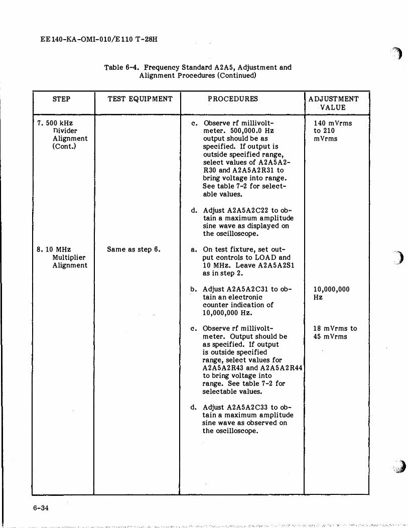
Table 6-4. Frequency Standard A2A5, Adjustment and Alignment Procedures (Continued)
TEST EQUIPMENT
Same as step 2.
Frequency Standard Test Fixture TS-3667 I WRC-1
RF Millivolt-meter 04901-92B-S5
RF Probe 04901-91-12F
Oscilloscope AN/USM-281
PROCEDURES
a. If the fine frequency ad-justment does not bring the 5 MHz output of the Frequency Standard Assem-bly into range, the INDEX will read 1 or 30. If this occurs, readjust the FINE FREQUENCY ADJUST cont-rol A2A5A1C2 to an INDEX reading of 17. Then remove the plug which covers the COARSE FREQUENCY AD-JUST and adjust the COARSE FREQUENCY ADJUST con-trol A2A5A1C3 with the aid of a nonmetallic or insu-lated shaft screwdriver un-til the electronic counter indicates 5,000,000.0 Hz ±{).2Hz.
b. Reattach plug over COARSE FREQUENCY AD-JUST control and repeat step 3.
a. Remove cover from A2A5. On test fixture set output controls to LOAD and INT 5 MHz. Leave A2A5A2S1 as in step 2.
b. Observe the rf millivolt-meter. If voltage out-side of specified range is indicated, select value of A2A5A2R49 to obtain re-quired result. See table 7-2 for selectable values.
c. Adjust A2A5A2C38 to ob-tain a maximum amplitude sine wave as displayed on the oscilloscope.
)
ADJUSTMENT VALUE
5,000,000.0 Hz
)
400 mVrms to 1200 mVrms
,<' ,;#
(
STEP
6. 1 MHz Divider Alignment
(
7. 500kHz Divider Alignment
(
EE140-KA-OMI-010/Ell0 T827H
Table 6-4. Frequency Standard A2A5, Adjustment and Alignment Procedures (Continued)
TEST EQUIPMENT
Frequency Standard Fixture TS-3667 I WRC-1
Electronic Counter AN/USM-207
RF Millivolt-meter 04901-92B-S5
RF Probe 04901-91-12F
Oscilloscope AN/USM-281
Same as step 6.
PROCEDURES
a. On test fixture set con-trois to read 1 MHz output and load output. Leave A2A5A2S1 as in step 2.
b. Adjust A2A5A2C7 to ob-tain an indication of 1,000,000.0 Hz on electronic counter.
c. Observe rf millivolt-meter. 1 MHz output should be as specified. If output outside speci-fied range is indicated, select values of A2A5A2R17 and A2A5A2-R18 to bring voltage to bring voltage into range. See table 7-2 for select-able values.
d. Adjust A2A5A2C13 to ob-tain a maximum amplitude sine wave as displayed on the oscilloscope.
a. On test fixture set output controls to LOAD and 500
kHz (A1). Leave A2A5A2-S1 as in step 2.
b. Adjust A2A5A2C16 to ob-tain an indication of 500,000.0 Hz on electronic counter.
ADJUSTMENT VALUE
1,000,000.0 Hz
300 mVrms to 600 mVrms
500,000.0 Hz
6-33
i I
I '
I
I
I
EE 140-KA-OMI-010/E 110 T-28H
STEP
7. 500kHz Divider Alignment (Cont.)
8. 10 MHz Multiplier Alignment
6-34
Table 6-4. Frequency Standard A2A5, Adjustment and Alignment Procedures (Continued)
TEST EQUIPMENT
Same as step 6.
PR OCEDURES
c. Observe rf millivolt-meter. 500,000.0 Hz output should be as specified. If output is outside specified range, select values of A2A5A2-R30 and A2A5A2R31 to bring voltage into range. See table 7-2 for select-able values.
d. Adjust A2A5A2C22 to ob-tain a maximum amplitude sine wave as displayed on the oscilloscope.
a. On test fixture, set out-put controls to LOAD and 10 MHz. Leave A2A5A2S1 as in step 2.
b. Adjust A2A5A2C31 to ob-tain an electronic counter indication of 10,000,000 Hz.
c. Observe rf millivolt-meter. Output should be as specified. If output is outside specified range, select values for A2A5A2R43 and A2A5A2R44 to bring voltage into range. See table 7-2 for selectable values.
d. Adjust A2A5A2C33 to ob-tain a maximum amplitude sine wave as observed on the oscilloscope.
-----·-··- -----
")
ADJUSTMENT VALUE
140 mVrms to 210 mVrms
I
)
10,000,000 Hz
18 mVrms to 45 mVrms
,,j
(
STEP
9. Automatic 5 MHz Source Switching Check and Adjustment
(
(
EE 140-KA-OMI-010/E 110 T827H
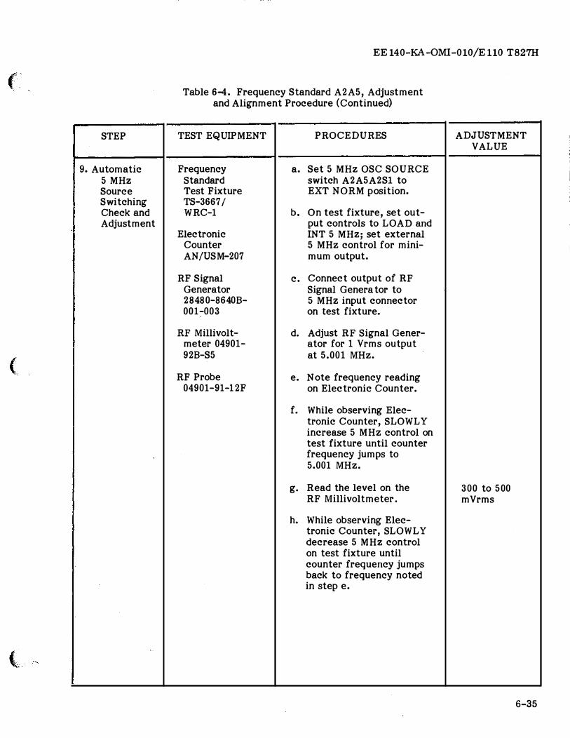
Table 6-4. Frequency Standard A2A5, Adjustment and Alignment Procedure (Continued)
TEST EQUIPMENT
Frequency Standard Test Fixture TS-3667/ WRC-1
Electronic Counter AN/USM-207
RF Signal Generator 28480-86408-001-003
RF Millivolt-meter 04901-928-S5
RF Probe 04901-91-12F
PROCEDURES
a. Set 5 MHz OSC SOURCE switch A2A5A2Sl to EXT NORM position.
b. On test fixture, set out-put controls to LOAD and INT 5 MHz; set external 5 MHz control for mini-mum output.
c. Connect output of RF Signal Genera tor to 5 MHz input connector on test fixture.
d. Adjust RF Signal Gener-ator for 1 Vrms output at 5.001 MHz.
e. Note frequency reading on Electronic Counter.
f. While observing Elec-tronic Counter, SLOWLY increase 5 MHz control on test fixture until counter frequency jumps to 5.001 MHz.
g. Read the level on the RF Millivoltmeter.
h. While observing Elec-tronic Counter, SLOWLY decrease 5 MHz control on test fixture until counter frequency jumps back to frequency noted in step e.
ADJUSTMENT VALUE
300 to 5 00 mVrms
6-35
EE140-KA-OMI-010/E110 T827H
STEP
9. Automatic 5 MHz Source Switching Check and Adjustment (Cont.)
10. Final Check
6-36
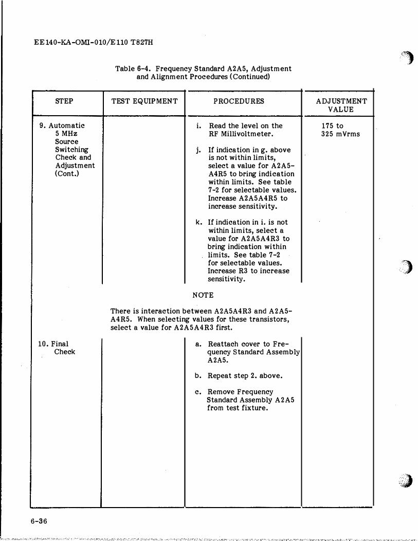
Table 6-4. Frequency Standard A2A5, Adjustment and Alignment Procedures (Continued)
TEST EQUIPMENT PROCEDURES
i. Read the level on the RF Millivoltmeter.
j. If indication in g. above is not within limits, select a value for A2A5-A4R5 to bring indication within limits. See table 7-2 for selectable values. Increase A2A5A4R5 to increase sensi ti vi ty.
k. If indication in i. is not within limits, select a value for A2A5A4R3 to bring indication within limits. See table 7-2 for selectable values. Increase R3 to increase sensitivity.
N OTE
There is interaction between A2A5A4R3 and A2A5-A4R5. When selecting values for these transistors, select a value for A2A5A4R3 first.
a. Reattach cover to Fre-quency Standard Assembly A2A5.
b. Repeat step 2. above.
c. Remove Frequency Standard Assembly A2A5 from test fixture.
ADJUSTMENT VALUE
175 to 325 mVrms
'�
' )' :,;,
o'ola :#
(j.) I
(Q -4
,..
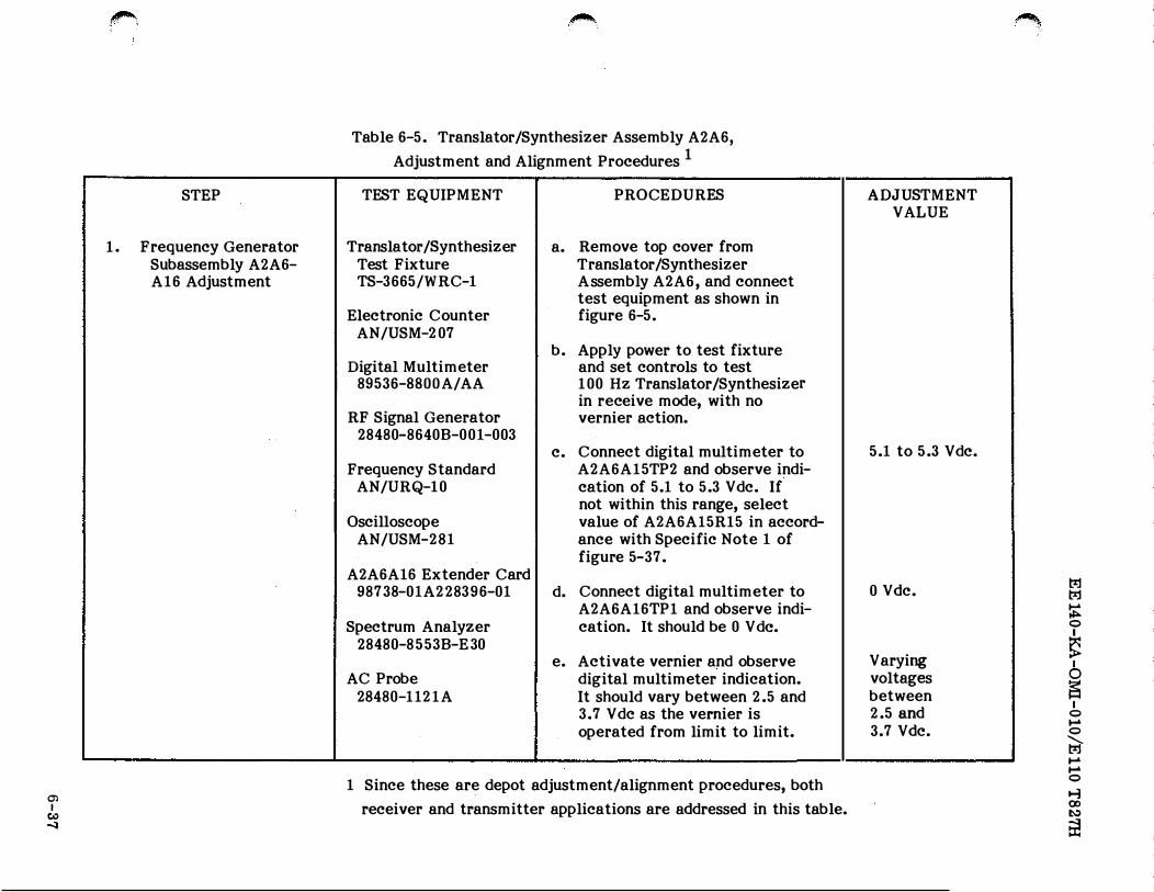
1.
STEP
Frequency Generator Subassembly A2A6-A16 Adjustment
�
Table 6-5. Translator/Synthesizer Assembly A2A6,
Adjustment and Alignment Procedures 1
TEST EQUIPMENT
Translator /Synthesizer Test Fixture TS-3665/WRC-1
Electronic Counter AN/USM-207
Digital Multimeter 89536-SS OOA/ AA
RF Signal Generator 28480-8640B-001-003
Frequency Standard AN/URQ-10
Oscilloscope AN/USM-281
A2A6A16 Extender Card 98738-01A228396-01
Spectrum Analyzer 28480-8553B-E 30
AC Probe 28480 -1121A
PROCEDURES
a. Remove top cover from Translator /Synthesizer Assembly A2A6, and connect test equipment as shown in figure 6-5.
b. Apply power to test fixture and set controls to test 100 Hz Translator/Synthesizer in receive mode, with no vernier action.
c. Connect digital multimeter to A2A6A15TP2 and observe indi-cation of 5.1 to 5.3 Vdc. If not within this range, select value of A2A6A15R15 in accord-ance with Specific Note 1 of figure 5-37.
d. Connect digital multimeter to A2A6A16TP1 and observe indi-cation. It should be 0 V de.
e. Activate vernier and observe digital multimeter indication. It should vary between 2.5 and 3.7 Vdc as the vernier is operated from limit to limit.
1 Since these are depot adjustment/alignment procedures, both
receiver and transmitter applications are addressed in this table.
ADJUSTMENT VALUE
5.1 to 5.3 Vdc.
0 Vdc.
Varying voltages between 2.5 and 3.7 Vdc.
'�
i I
I
t:r.:1 t:r.:1
� 0 I
� I
0
� I
0 ..... 0
� ..... ..... 0
...., 00 �
�
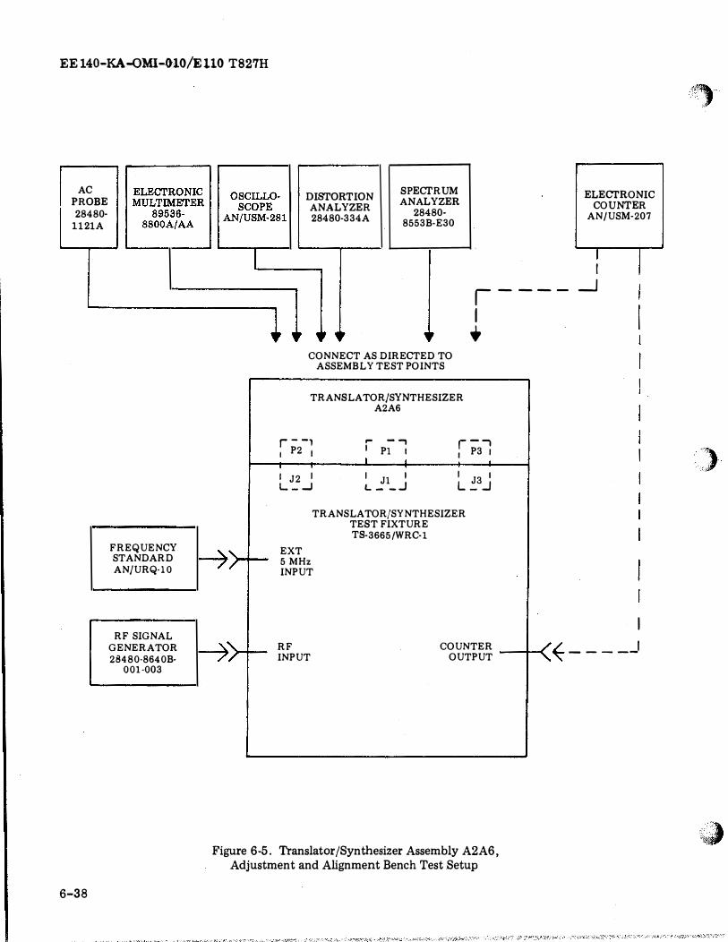
EE 140-KA-QMI-010/E 110 T827H
AC ELECTRONIC ELECTRONIC PROBE MULTIMETER MULTIMETER 28480· 89536-89536-
1121A
6-38
8800A/AA 8800A/AA
F REQUENCY STANDARD AN/URQ-10
RF SIGNAL GENERATOR 28480-8640B-
001-003
OSCILLO· OSCILLO· DISTORTION ANALYZER 28480-334A
SPECTRUM ANALYZER
28480· 8553B·E30
SCOPE SCOPE AN/USM-28 AN/USM-281
I
�>+-
.....
l •
CONNECT AS DIRECTED TO ASSEMBLY TEST POINTS
,----1
+
TRANSLATOR/SYNTHESIZER A2A6
--, r P2 1 '
I J2 I L_...J
,.. --, I Pl I I
I Jl I L- _.J
r-, P3 I I
I JS I L _ _J
TRANSLATOR/SYNTHESIZER TEST FIXTURE TB-3665 /WRC-1
EXT 5 MHz INPUT
ELECTRONIC COUNTER
AN/USM-207
T I
_J
I
I
�>+- RF INPUT
COUNTER I "L I OUTPUT ----t-(_ � - - - --
Figure 6-5. Translator/Synthesizer Assembly A2A6, Adjustment and Alignment Bench Test Setup
"�
�)
:�
� I
Col) (s;J
"
1.
L...__ --··-
STEP
Frequency Generator Subassembly A2A6-A16 Adjustment (Cont.)
-
-
,..,,
Table 6-5. Translator/Synthesizer Assembly A2A6, Adjustment and Alignment Procedures (Continued)
TEST EQUIPMENT PROCEDURES
f. Connect the rf signal gener-ator to the RF input con-nector on the test fixture. Set output of the rf signal generator to 5.000 MHz at a level of 5 m Vrms.
g. Tune the Translator/Synthesizer to 5.001 MHz by means of test fixture controls.
h. Connect ac probe and spectrum analyzer with tracking gener-ator in RESTORE SIGNAL mode to A2A6A8TP8. With the vernier control fully counter-clockwise, observe an indica-tion of 499.2 to 499.4 kHz. If necessary, adjust A2A6Al6-R22 to obtain the correct indication.
i. With the equipment connected as in Step h, and with the vernier control fully clock-wise, observe an indication of 497.6 to 497.8 kHz on the counter. If necessary, adjust A2A6A16R18 to obtain the correct indication.
�'
ADJUSTMENT VALUE
499.2 to 499.4 kHz.
497.6 to 497.8 kHz.
·trl trl
� 0
� I
0
� I
0 ..... 0
l;j ..... ..... 0
� 00 I.\)
�
STEP
1. Frequency Generator S ubassembly A2A6-A16 Adjustment (Cont.)
- :..!· ilia: & -I !
I ! - II'
I' I,
WAVEFORM A
I I I II, I, I. ' ! I '
11:'• 11• i' h ,, f 1, . ! '
I ! • : i n •
\ \
!
\
II-
i I,
••+-:; II, ni ---+-' ��_,1'
WAVEFORMB
I I I I, I I I I
r-- r.:: :: I � ' I I
I I
I I. -�- , 1
• I I' I I
WAVEFORM C
Table 6-5. Translator/S ynthesizer Assembly A2A6, Adjustment and Alignment P rocedures (Continued)
TEST EQUIPMENT P ROCEDURES
j. Repeat steps h. and i. Adjust if necessary to obtain the required indications.
k. Connect the oscilloscope to A2A6A16TP2. Disable vernier. Observe Waveform A. (Rectangular pulses at an amplitude of 4 V P-P and period of 1000 :±4 usee.)
l. Enable vernier. Observe waveform similar to Waveform A. Connect counter to A2A6A16TP2 and observe counter variation between 1000.1 Hz and 999.7 Hz as the vernier is operated. Disable vernier.
m. Connect oscilloscope and counter to A2A6A16TP3. Observe Waveform B. (Pulses at an amplitude of 4 V P-P and a frequency of 100kHz.)
n. Connect oscilloscope to A2A6A16TP4. Observe Waveform C. (Rectangular pulses at an amplitude of 4 V P-P and a frequency of 500kHz.)
ADJUSTMENT VALUE
(1) I
tf>. .....
�""'·
2.
STEP
Synthesizer A2A6-A17 Adjustment
. �
Table 6-5. Translator/Synthesizer Assembly A2A6 Adjustment and Alignment Procedures (Continued)
TEST EQUIPMENT
Translator /Synthesizer Test Fixture TS-3665/ WRC-1
Oscilloscope AN /USM-281 with Test Probe (10:1 attenuation)
Distortion Analyzer 28480-334A
Frequency Standard AN/URQ-10
RF Signal Generator 28480-8640B-001-003
A2A6A17 Extender Card 98738-01A228398-01
Spectrum Analyzer 28480-8553B-E30
AC Probe 28480-1121A
Digital Multimeter 89536-8800A/AA
PROCEDURES
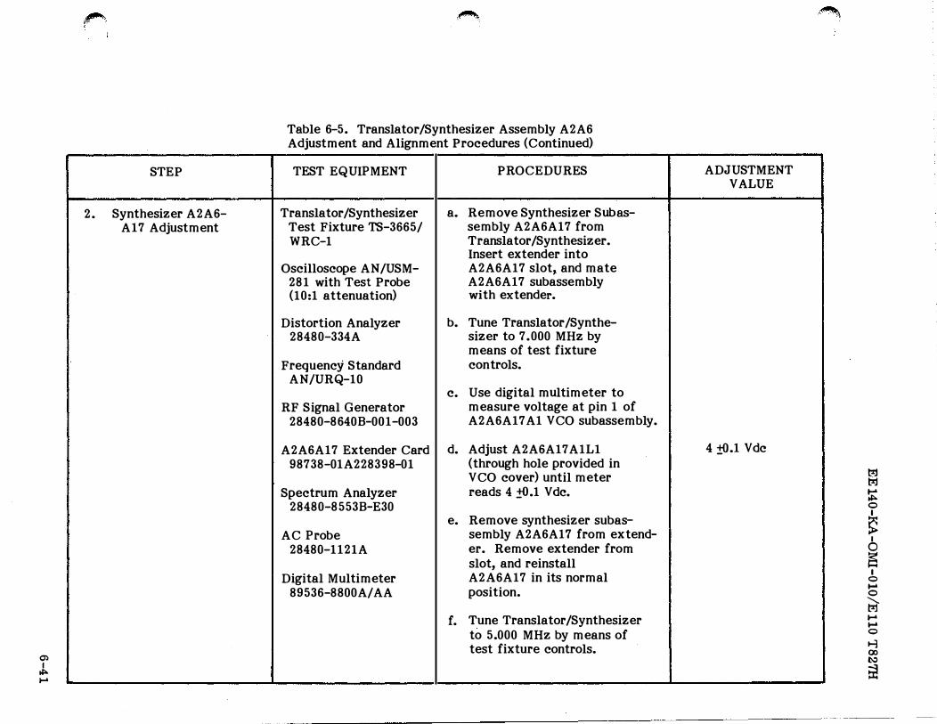
a. Remove Synthesizer Subas-sembly A2A6A17 from Translator /Synthesizer. Insert extender into A2A6A17 slot, and mate A2A6A17 subassembly with extender.
b. Tune Translator /Synthe-sizer to 7.000 MHz by means of test fixture controls.
c. Use digital multimeter to measure voltage at pin 1 of A2A6A17 A1 VCO subassembly.
d. Adjust A2A6A17 A1L1 (through hole provided in VCO cover) until meter reads 4 :!().1 Vdc.
e. Remove synthesizer subas-sembly A2A6A17 from extend-er. Remove extender from slot, and reinstall A2A6A17 in its normal position.
f. Tune Translator/Synthesizer to 5.000 MHz by means of test fixture controls.
·� .
ADJUSTMENT VALUE
4 ±().1 Vdc
�
� � 0 I
� I
0
� I
0
..... 0
t;a-..... ..... 0
� 00 N
Ei!
STEP
2. Synthesizer A2A6-A17 Adjustment (Cont.)
Table 6-5. Translator/Synthesizer Assembly A2A6, Adjustment and Alignment Procedures (Continued)
TEST EQUIPMENT PROCEDURES
g. Remove side panel from Translator /Synthesizer as-sembly for access to trans-lator subassembly A2A6A8, and connect well grounded 10:1 probe on oscilloscope to A2A6A8E8. Adjust A2A6A17R10 to obtain a sine wave at an amplitude of 100 mV P-P. Connect ac probe and spectrum analyzer with tracking generator in RESTORE SIGNAL mode to A2A6A17TP3 and measure frequency of 22.4 MHz ±100 Hz.
h. Tune Translator/Synthesizer to 6.000 MHz by means of test fixture controls. The frequency as read on the tracking generator at A2A6A17TP3 shall be 32.4 MHz ±100 Hz. The amplitude of the sine wave at A2A6A8E8 shall be 100 ±15 mV P-P.
i. Connect distortion analyzer to A2A6P2A1 (IF OUT) or A2A6A8-TPS. Set output of rf signal gen-erator connected to rf input of test fixture to 6.000 MHz at a level of 5 m V rms.
ADJUSTMENT VALUE
100 mV P-P
(j)
I ""' Co)
,....,
2.
STEP
Synthesizer A2A6-A17 Adjustment (Cont.)
�.
Table 6-5. Translator/Synthesizer Assembly A2A6, Adjustment and Alignment Procedures (Continued)
TEST EQUIPMENT PROCEDURES
NOTE
If it is not possible to set level on distortion analyzer with sensitivity and vernier at max. then increase output of rf signal generator slightly as necessary.
j. Measure the distortion.
k. Change the signal generator and test fixture frequencies to 7.000 MHz, and measure distortion.
1. If distortion in steps j. or k.is greater than 1.596, replace A2A6A17 Al VCO sub-assembly and repeat steps a. through k.
m. Disconnect external test equipment.
n. Connect oscilloscope to A2A6A17TP1. Observe Wave-form B. (Pulses at an ampli-tude of 4 V p-p and a fre-quency of 100kHz.)
ADJUSTMENT VALUE
1.596 or less distortion
1.596 or less distortion.
1.596 or less distortion.
�.
t:oj t:oj
� 0 I
� 6 � I
0 ..... 0
t;a-....
..... 0
t-1 ()) l\)
�
m l:Jj I l:Jj II>- Table 6-5. Translator/Synthesizer Assembly A2A6, II>- .....
Adjustment and Alignment Procedures (Continued) II>-0
STEP TEST EQUIPMENT PROCEDURES ADJUSTMENT � VALUE 6
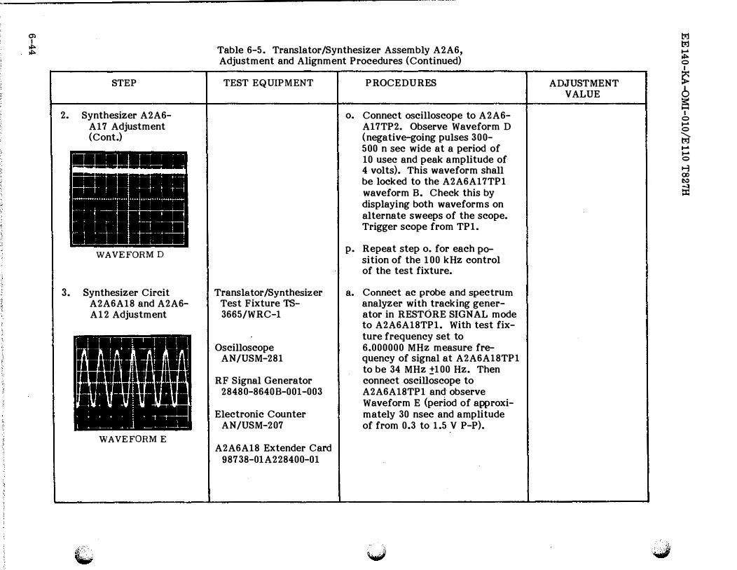
r:s 2. Synthesizer A2A6- o. Connect oscilloscope to A2A6- I
0
A17 Adjustment A17TP2. Observe Waveform D ..... 0
(Cont.) (negative-going pulses 300- t;a-500 n sec wide at a period of .....
.....
10 usee and peak amplitude of 0
4 volts). This waveform shall � 00
be locked to the A2A6A17TP1 1,\:)
waveform B. Check this by � displaying both waveforms on alternate sweeps of the scope. Trigger scope from TP1.
WAVEFORM D p. Repeat step o. for each po-
sition of the 100 kHz control of the test fixture.
3. Synthesizer Circit Translator/Synthesizer a. Connect ac probe and spectrum A2A6A18 and A2A6- Test Fixture TS- analyzer with tracking gener-A12 Adjustment 3665/WRC-1 ator in RESTORE SIGNAL mode
to A2A6A18TP1. With test fix-ture frequency set to
Oscilloscope 6.000000 MHz measure fre-AN/USM-281 quency of signal at A2A6A18TP1
to be 34 MHz ±100 Hz. Then RF Signal Generator connect oscilloscope to
28480-8640B-001-003 A2A6A18TP1 and observe Waveform E (period of approxi-
Electronic Counter mately 30 nsec and amplitude AN/USM-207 of from 0.3 to 1.5 V P-P).
WAVEFORM E A2A6A18 Extender Card
98738-01A228400-01
�
I ""' 01
,...,
STEP
3. Synthesizer Circuit A2A6A18 and A2A6-A12 Adjustment (Cont.)
I!!!!!!!!!!!!!!!!--=
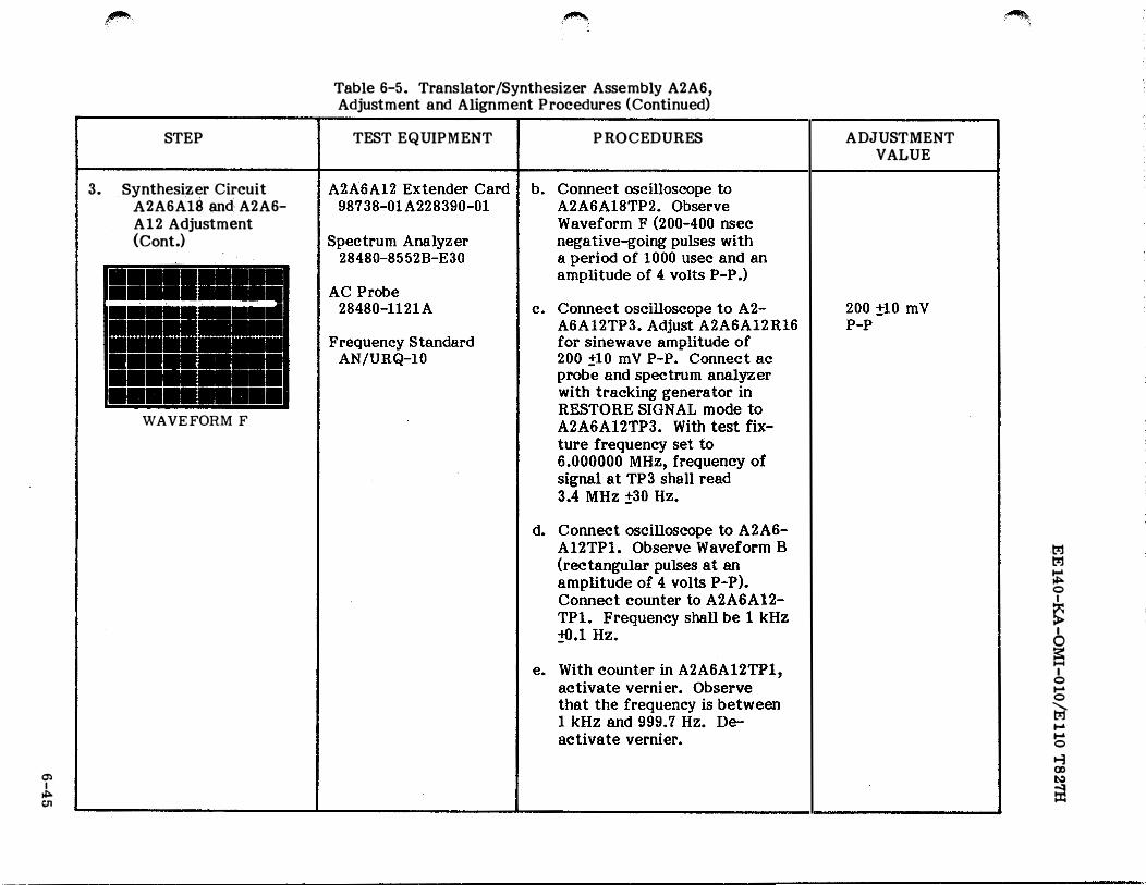
..... 1 WAVEFORM F
�
Table 6-5. Translator/Synthesizer Assembly A2A6, Adjustment and Alignment Procedures (Continued)
TEST EQUIPMENT PROCEDURES ADJUSTMENT VALUE
·�
.t;r.j t;r.j
� 0
� I
� I
0 .... 0
� .... .... 0
� (X) �
fi1
0) l:%j
i l:%j Table 6-5. Translator/Synthesizer Assembly A2A6, ....
0) .,.. Adjustment and Alignment Procedures {Continued} 0
I
STEP TEST EQUIPMENT PROCEDURES ADJUSTMENT � I
VALUE 0
� 3. Synthesizer Circuit f. Connect oscilloscope to
I 0
A2A6A18 and A2A6A12TP2. Observe .... 0
A2A6A12 Waveform F (200-400 nsec t;;] Adjustment negative-going pulses with ....
....
(Cont.} a period of 1000 usee and 0
an amplitude of 4 volts P-P). ..., 00
This waveform shall be 1:\:1
locked to the A2A6A12TP1 � Waveform B. Check this by displaying both waveforms on alternate sweeps of the oscilloscope.
g. Repeat step f. for each po-sition of the 100 Hz, 1 kHz and 10 kHz frequency controls of the test fixture.
4. Synthesizer Sub- Translator /Synthesizer a. Connect oscilloscope to assembly A2A6A13 Test Fixture TS- A2A6A13TP1. Observe
3665/WRC-1 Waveform G (negative-going pulses 40 to 400 nsec wide
Oscilloscope AN/ at a period of 2 usee and a USM-281 peak amplitude of 4 volts
P-P). The width depends Frequency Standard upon MHz setting.
AN/URQ-10
A2A6A13 Extender Card 98738-
I!!!! I I, I - i H I
II II I I
I'
!t- u' I
- - -·- _u, __ ,L = ==--:• -- -l
i WAVEFORMG 01A228392-01
a;, I
""" -'1
""
STEP
4 . Synthesizer Subassembly A2A6Al3 (Cont.)
= = ••• - - - .....
:::;; = -:;;; = -= -I
··-· - ·
+ .
L_l' WAVEFORM H
• P"' ,.... II ,....
I' r• ,. I
I
to.l- j l: -� :• !!l PJ , ..
i -IIIII -
�I- I WAVEFORM I
.�
Table 6-5. Translator/Synthesizer Assembly A2A6, Adjustment and Alignment Procedures (Continued)
TEST EQUIPMENT PROCEDURES
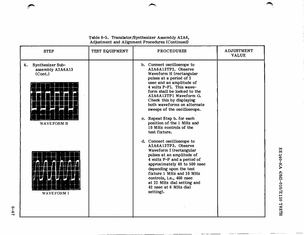
b. Connect oscilloscope to A2A6A13TP2. Observe Waveform H (rectangular pulses at a period of 2 usee and an amplitude of 4 volts P-P). This waveform shall be locked to the A2A6A13TP1 Waveform G.
Check this by displaying both waveforms on alternate sweeps of the oscilloscope.
c. Repeat Step b. for each position of t'he 1 MHz and 10 MHz controls of the test fixture.
d. Connect oscilloscope to A2A6A13TP3. Observe Waveform I (rectangular pulses at an amplitude of 4 volts P-P and a period of approximately 40 to 500 nsec depending upon the test fixture 1 MHz and 10 MHz controls, i.e., 400 nsec at 22 MHz dial setting and 42 nsec at 6 MHz dial setting).
ADJUSTMENT VALUE
�
t.'Jj trl
� 0
� I
0
E5 I
0 1-' 0
r;a-1-' 1-' 0
� (XI !:-:>
ill
(j) I
""" 00
5.
STEP
10 MHz/1 MHz Filter Subassembly A2A6A14 Adjustment
WAVEFORM J
Table 6-5. Translator/Synthesizer Assembly A2A6, Adjustment and Alignment Procedures (Continued)
TEST E QUIPMENT
Translator /Synthesizer Test Fixture TS-
3665/WRC-1
Multimeter AN/USM-311
Oscilloscope AN/USM-281
Frequency Standard AN/URQ-10
A2A6A14 Extender Card 98738-01A228394-01
P RO CEDURES
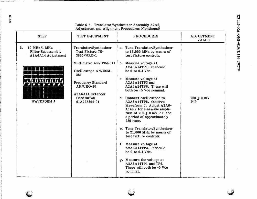
a. Tune Translator/Synthesizer to 16.000 MHz by means of test fixture controls.
b. Measure voltage at A2A6A14TP1. It should be 0 to 0.4 Vdc.
c Measure voltage at A2A6A14TP3 and A2A6A14TP6. These will both be +5 Vdc nominal.
d. Connect oscilloscope to A2A6Al4TP5. Observe Waveform J. Adjust A2A6-Al4R7 for sinewave amplitude of 200 ±10 mV P-P and a period of approximately 280 nsec.
e. Tune Translator/Synthesizer to 21.000 MHz by means of test fixture controls.
f. Measure voltage at A2A6A14TP3. It should be 0 to 0.4 Vdc.
g. Measure the voltage at A2A6A14TP1 and TP6. These will both be +5 V de nominal.
ADJUSTMENT VALUE
200 ±10 mV P-P
"*'·
STEP
5. 10 MHz/1 MHz Filter Subassembly A2A6A14 Adjustment (Cont.)
CD
J,. co
�-
Table 6-5. Translator/Synthesizer Assembly A2A6, Adjustment and Alignment Procedures (Continued)
TEST EQUIPMENT PROCEDURES
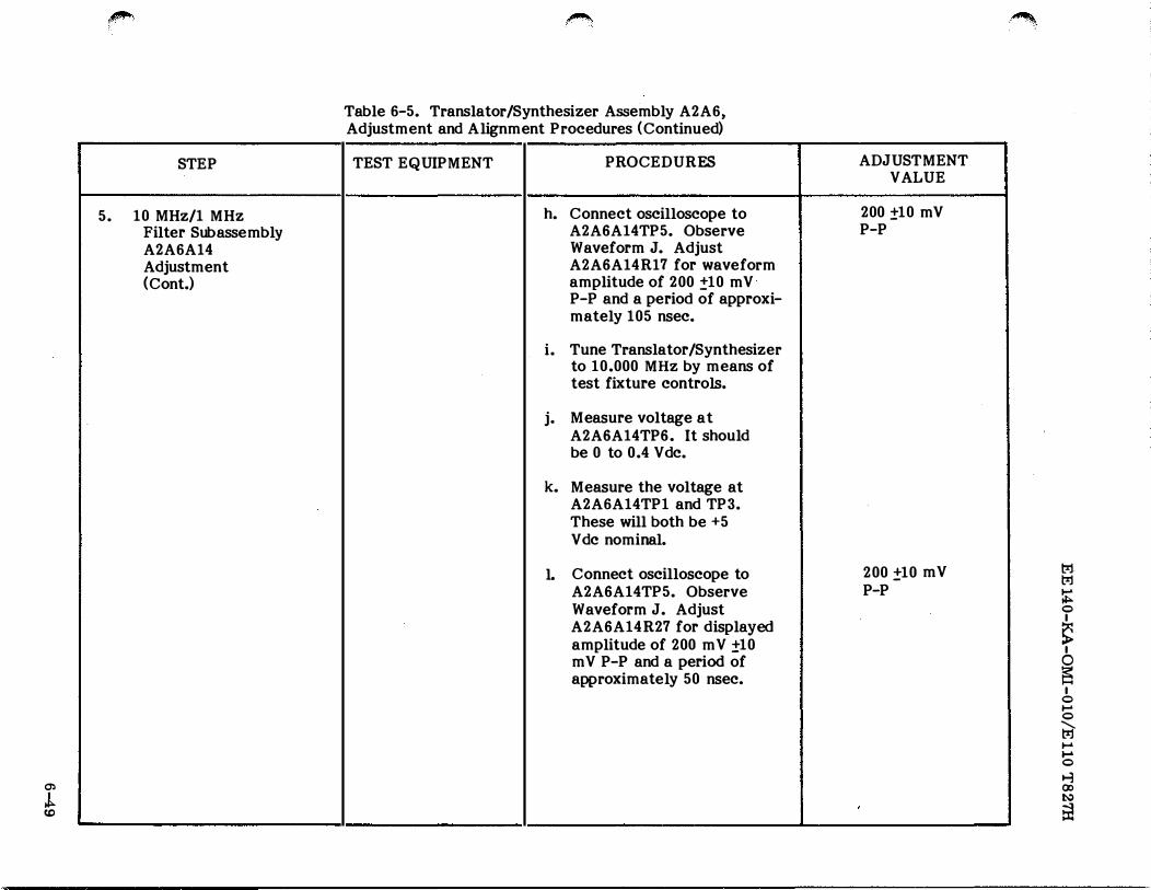
h. Connect oscilloscope to A2A6A14TP5. Observe Waveform J. Adjust A2A6A14R17 for waveform amplitude of 200 :!10 mV P-P and a period of approxi-mately 105 nsec.
i. Tune Translator/Synthesizer to 10.000 MHz by means of test fixture controls.
j. Measure voltage at A2A6A14TP6. It should be 0 to 0.4 Vdc.
k. Measure the voltage at A2A6A14TP1 and TP3. These will both be +5 Vdc nominal.
1. Connect oscilloscope to A2A6A14TP5. Observe Waveform J. Adjust A2A6A14R27 for displayed amplitude of 200 m V ±10 m V P-P and a period of approximately 50 nsec.
ADJUSTMENT VALUE
200 ±10 mV P-P
200 ±10 mV P-P
'
�
I
t-j. t-::1
� 0 I
� I
� I
0 ...... 0
t;? ...... ..... 0
t-1 00 J:o.:)
til
O'l I
CJl 0
6.
STEP
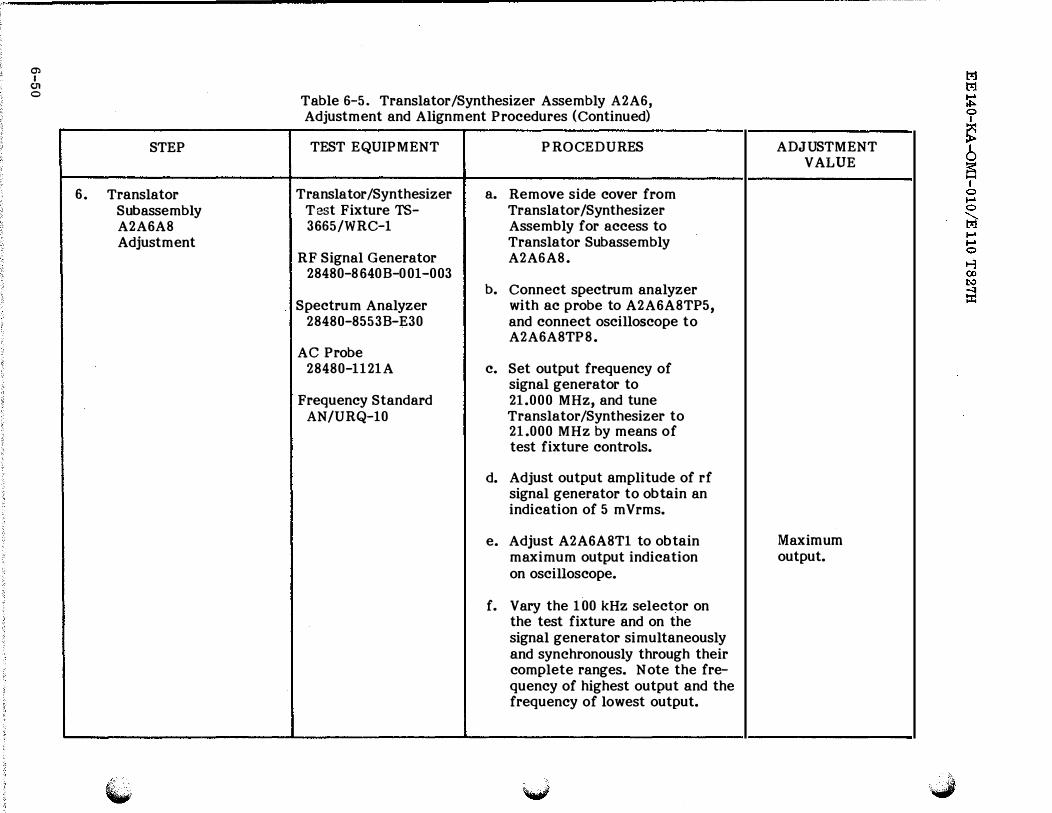
Translator Subassembly A2A6A8 Adjustment
Table 6-5. Translator/Synthesizer Assembly A2A6, Adjustment and Alignment Procedures (Continued)
TEST EQUIPMENT PROCEDURES
Translator /Synthesizer a. Remove side cover from Test Fixture TS- Translator /Synthesizer 3665/WRC-1 Assembly for access to
Translator Subassembly RF Signal Generator A2A6A8.
28480-8640B-001-003 b. Connect spectrum analyzer
Spectrum Analyzer with ac probe to A2A6A8TP5, 28480-8553B-E30 and connect oscilloscope to
A2A6A8TP8. AC Probe
28480-1121A c. Set output frequency of signal generator to
Frequency Standard 21.000 MHz, and tune AN/URQ-10 Translator /Synthesizer to
21.000 MHz by means of test fixture controls.
d. Adjust output amplitude of rf signal generator to obtain an indication of 5 mVrms.
e. Adjust A2A6A8T1 to obtain maximum output indication on oscilloscope.
f. Vary the 1 00 kHz selector on the test fixture and on the signal generator simultaneously and synchronously through their complete ranges. Note the fre-quency of highest output and the frequency of lowest output.
ADJUSTMENT VALUE
Maximum output.
(!') I
tTl
...
,...,
6.
STEP
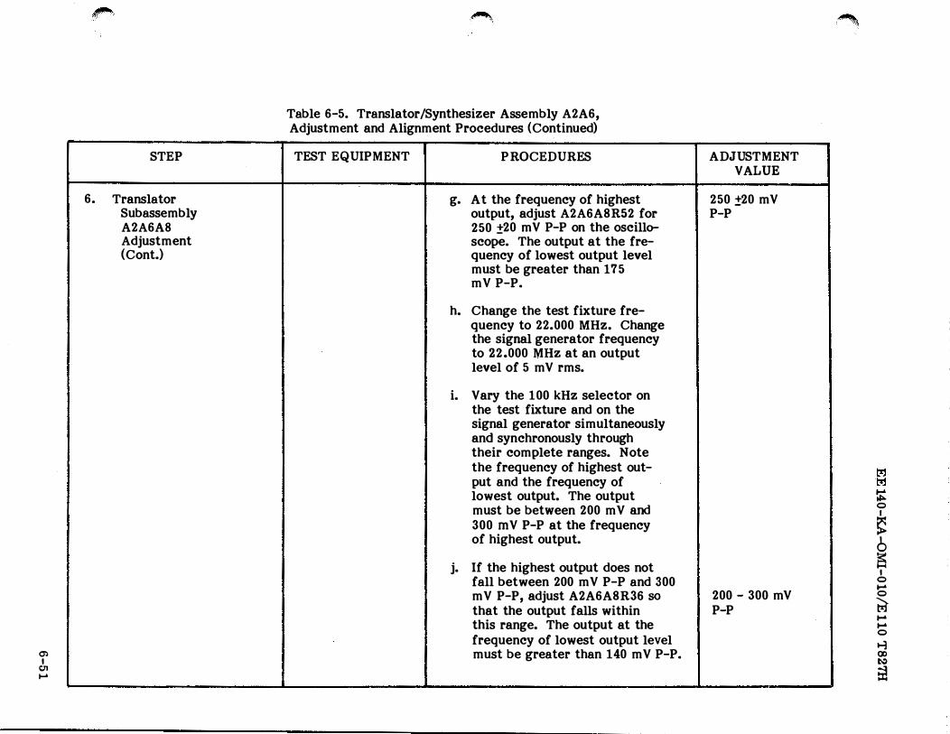
Translator Subassembly A2A6A8 Adjustment (Cont.)
�
Table 6-5. Translator/Synthesizer Assembly A2A6, Adjustment and Alignment Procedures (Continued)
TEST EQUIPMENT
� --
PROCEDURES
g. At the frequency of highest output, adjust A2A6A8R52 for 250 ±20 mV P-P on the oscillo-scope. The output at the fre-quency of lowest output level must be greater than 17 5 mV P-P.
h. Change the test fixture fre-quency to 22.000 MHz. Change the signal generator frequency to 22.000 MHz at an output level of 5 m V rms.
i. Vary the 100kHz selector on the test fixture and on the signal generator simultaneously and synchronously through their complete ranges. Note the frequency of highest out-put and the frequency of lowest output. The output must be between 200 m V and
300 mV P-P at the frequency of highest output.
j. If the highest output does not fall between 200 m V P-P and 300 mV P-P, adjust A2A6A8R36 so
that the output falls within this range. The output at the frequency of lowest output level must be greater than 140 mV P-P.
�.
ADJUSTMENT VALUE
250 ±20 mV P-P
!
200 - 300 mV P-P
t.%j t.%j
� 0 I
� 6 E5
I 0 ... 0
� ... ... 0
t-1 (X) �
5!
STEP
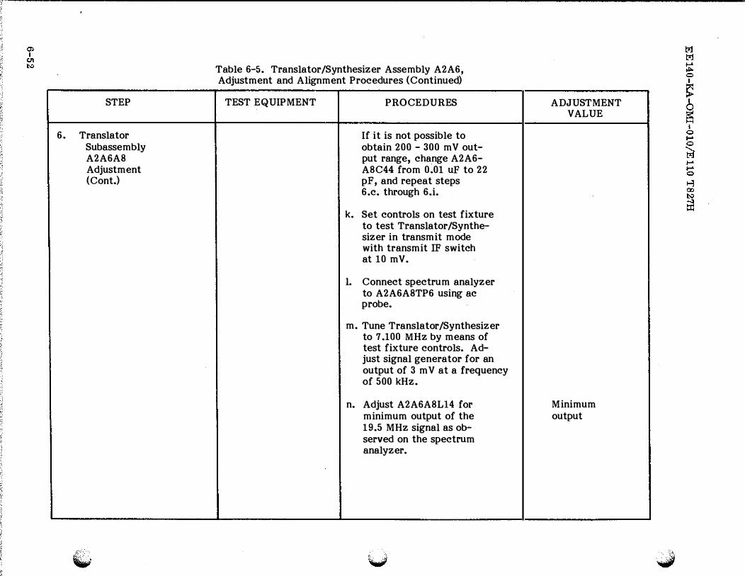
6. Translator Subassembly A2A6A8 Adjustment (Cont.)
Table 6-5. Translator/Synthesizer Assembly A2A6, Adjustment and Alignment Procedures (Continued)
TEST EQUIPMENT PROCEDURES
If it is not possible to obtain 200 - 300 mV out-put range, change A2A6-A8C44 from 0.01 uF to 22 pF, and repeat steps 6.c. through 6.i.
k. Set controls on test fixture to test Translator/Synthe-sizer in transmit mode with transmit IF switch at 10 mV.
1. Connect spectrum analyzer to A2A6A8TP6 using ac probe.
m. Tune Translator/Synthesizer to 7.100 MHz by means of test fixture controls. Ad-just signal generator for an output of 3 m V at a frequency of 500kHz.
n. Adjust A2A6A8L14 for minimum output of the 19.5 MHz signal as ob-served on the spectrum analyzer.
ADJUSTMENT VALUE
Minimum output
(j) I
(11 ""
6
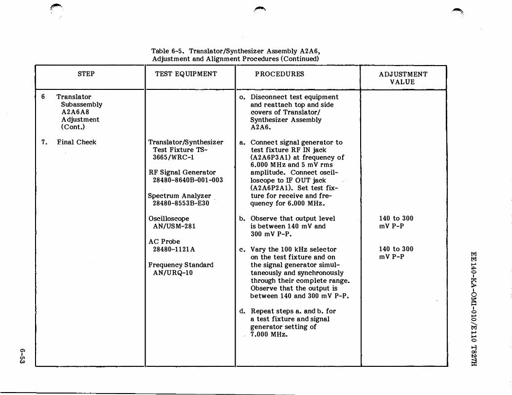
7.
#"""·
STEP
Translator Subassembly A2A6A8 A djustment ( Cont.)
Final Check
�'
Table 6-5. Translator/Synthesizer Assembly A2A6, Adjustment and Alignment Procedures ( Continued)
TEST EQUIPMENT
Translator /Synthesizer Test Fixture TS-
3665/WRC-1 I
RF Signal Generator 28480-8640B-001-003
Spectrum Analyzer 28480-8553B-E30
Oscilloscope AN/USM-281
AC Probe 28480-1121A
Frequency Standard AN/URQ-10
PROCEDURES
o. Disconnect test equipment and reattach top and side covers of Translator/ Synthesizer Assembly A2A6.
a. Connect signal generator to test fixture RF IN jack (A2A6P3A1) at frequency of 6.000 MHz and 5 mV rms amplitude. Connect oscil-loscope to IF 0 UT jack (A2A6P2A1). Set test fix-ture for receive and fre-quency for 6.000 MHz.
b. Observe that output level is between 140 mV and 300 mV P-P.
c. Vary the 100 kHz selector on the test fixture and on the signal generator simul-taneously and synchronously through their complete range. Observe that the output is
between 140 and 300 m V P-P.
d. Repeat steps a. and b. for a test fixture and signal generator setting of 7.000 MHz.
�.
ADJUSTMEN T VALUE
140 to 300 mV P-P
140 to 300 mV P-P trJ
trJ
� 0
I
� I
� I
0 t-Jo 0
� t-Jo t-Jo 0
....:j 00 �
6:!
STEP
7. Final Check (Cont.)
\.}
Table 6-5. Translator/Synthesizer Assembly A2A6, Adjustment and Alignment Procedures (Continued)
TEST EQUIPMENT PROCEDURES
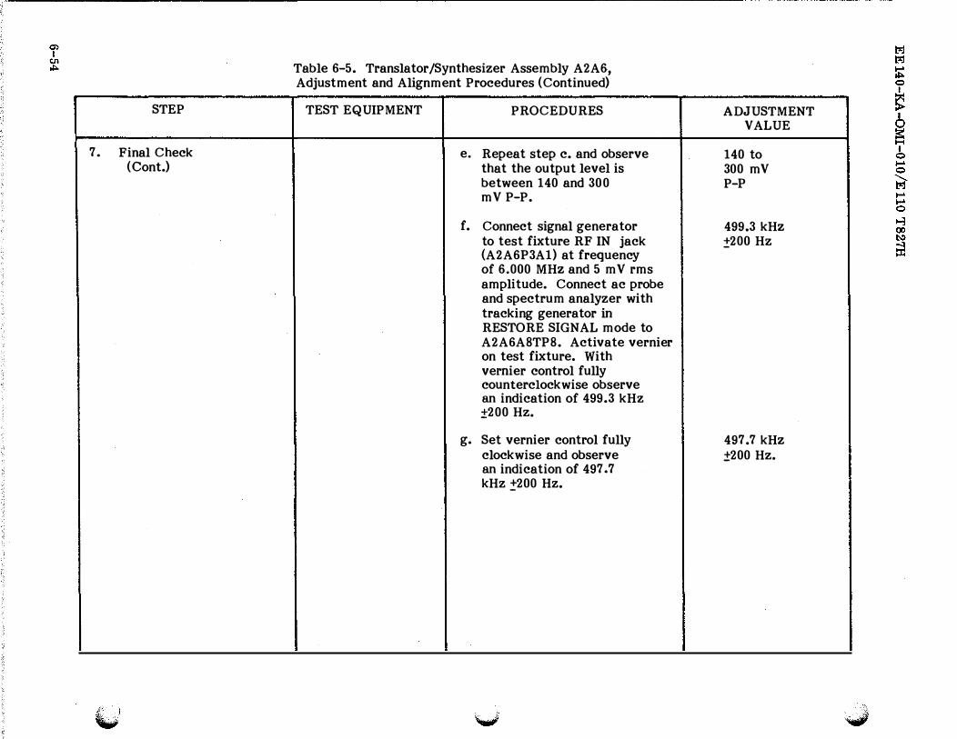
e. Repeat step c. and observe that the output level is between 140 and 300 mV P-P.
f. Connect signal generator to test fixture RF IN jack (A2A6P3A1) at frequency of 6.000 MHz and 5 mV rms amplitude. Connect ac probe and spectrum analyzer with track ing generator in
RESTORE SIGNAL mode to A2A6A8TP8. Activate vernier on test fixture. With vernier control fully counterclockwise observe an indication of 499.3 kHz ±200 Hz.
g. Set vernier control fully clockwise and observe an indication of 497.7 kHz !'200 Hz.
ADJUSTMENT VALUE
140 to 300 mV P-P
499.3 kHz ±200Hz
497.7 kHz ±200Hz.
(j) I
01
01
7.
'--- -
_,_..,
STEP
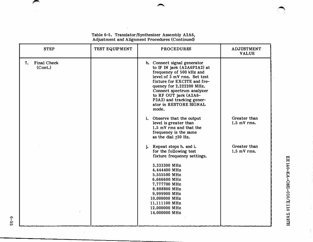
Final Check (Cont.)
----------�-----
�
Table 6-5. Translator/Synthesizer Assembly A2A6, Adjustment and Alignment Procedures (Continued)
TEST EQUIPMENT PROCEDURES
h. Connect signal generator to IF IN jack (A2A6P2A2) at frequency of 500 kHz and level of 3 m V rms. Set test fixture for EXCITE and fre-quency for 2.222200 MHz. Connect spectrum analyzer to RF OUT jack (A2A6-P3A2) and tracking gener-ator in RESTORE SIGNAL mode.
i. Observe that the output level is greater than 1.5 mV rms and that the frequency is the same as the dial .±30 Hz.
j. Repeat steps h. and i. for the following test fixture frequency settings.
3.333300 MHz 4.444400 MHz 5.555500 MHz 6.666600 MHz 7. 777700 MHz 8.888800 MHz 9.999900 MHz
10.000000 MHz 11.111100 MHz 12.000000 MHz 14.000000 MHz
- -- -------�----------- ------- -- - --�---- - - - ------
ADJUSTMENT VALUE
Greater than 1.5 mV rms.
Greater than 1.5 mV rms.
---- L . ... �-
�-
t1j 1?=.1
� 0 I
� I
0
� I
0 ...-0
� ......-0
� 00 t-:1
a1
STEP
7. Final Check (Cont.)
Table 6-5. Translator /Synthesizer Assembly A2A6, Adjustment and Alignment Procedures (Continued)
TEST EQUIPMENT P ROCEDURES
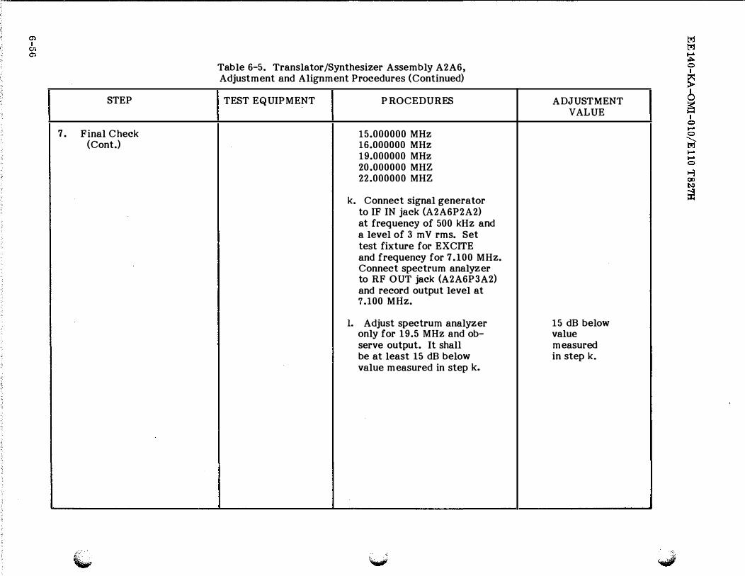
15.000000 MHz 16.000000 MHz 19.000000 MHz 20.000000 MHZ 22.000000 MHZ
k. Connect signal generator to IF IN jack (A2A6P2A2) at frequency of 500 kHz and a level of 3 m V rms. Set test fixture for EXCITE and frequency for 7.100 MHz. Connect spectrum analyzer to RF OUT jack (A2A6P3A2) and record output level at 7.100 MHz.
1. Adjust spectrum analyzer only for 19.5 MHz and ob-serve output. It shall be at least 15 dB below value measured in step k.
ADJUSTMENT VALUE
15 dB below value measured in step k.
f
STEP
1. Preliminary
(
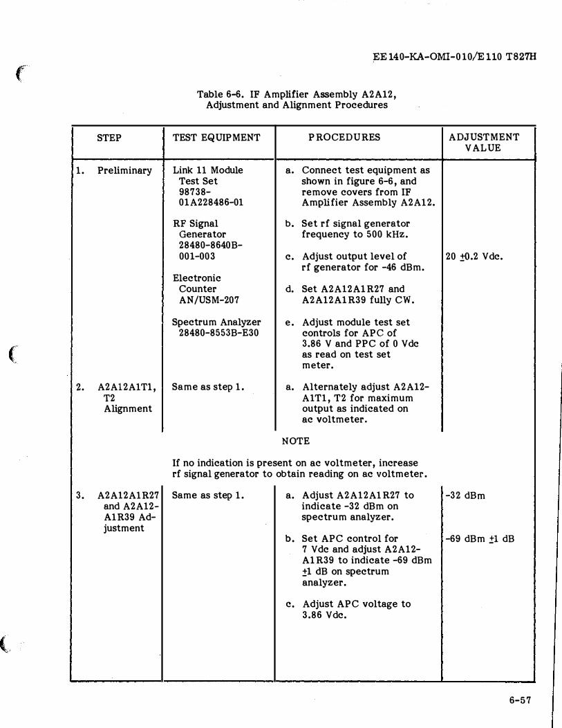
2. A2Al2A1Tl, T2 Alignment
3. A2Al2A1R27 and A2Al2-A1R39 Ad-justment
(
EE 140-KA-OMI- 010/E 110 T827H
Table 6-6. IF Amplifier Assembly A2A12, Adjustment and Alignment Procedures
TEST EQUIPMENT
Link 11 Module Test Set 98738-01A228486-0l
RF Signal Generator 28480-8640B-001-003
Electronic Counter AN/USM-207
Spectrum Analyzer 28480-8553B-E30
Same as step 1.
PROCEDURES
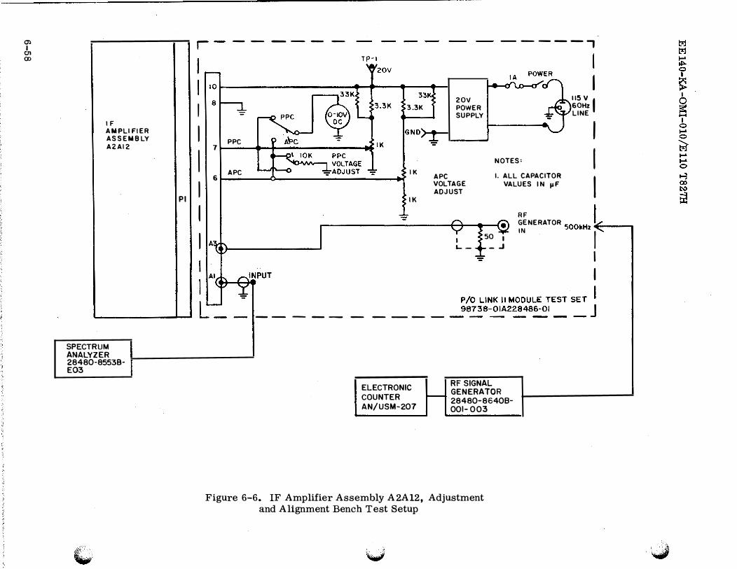
a. Connect test equipment as shown in figure 6-6, and remove covers from IF Amplifier Assembly A2A12.
b. Set rf signal generator frequency to 500 kHz.
c. Adjust output level of rf generator for -46 dBm.
d. Set A2Al2A1R27 and A2Al2A1R39 fully CW.
e. Adjust module test set controls for APC of 3.86 V and PPC of 0 Vdc as read on test set meter.
a. Alternately adjust A2A12-AlTl, T2 for maximum output as indicated on ac voltmeter.
NOTE
If no indication is present on ac voltmeter, increase rf signal generator to obtain reading on ac voltmeter.
Same as step 1. a. Adjust A2Al2A1R27 to indicate -32 dBm on spectrum analyzer.
b. Set APC control for 7 Vdc and adjust A2Al2-AlR39 to indicate -69 dBm ±1 dB on spectrum analyzer.
c. Adjust APC voltage to 3.86 Vdc.
ADJUSTMENT VALUE
'
I
'
20 ±{).2 Vdc.
!
-32 dBm
-69 dBm .±1 dB
-6-57
0)
I CJ1
(X)
IF
AMPLIFIER ASSEMBLY AZAI2
SPECTRUM ANALYZER 28480-8553BE03
I I I
PI I I I
7
6
------
=
PPC
APC
33K
3.3K
IK
IK
----------
ELECTRONIC COUNTER AN/USM-207
--- --,
20V POWER SUPPLY
115 v I 60Hz LINE
NO TES:
I
I
I APC VOLTAGE ADJUST
I. ALL C APACITOR VALUES IN I'F
I L--
50 1
_.J
RF SIGNAL GENERATOR 28480-86408-001- 0 03
RF I �;NERATOR 500kHz�--.,
I I
I I
Figure 6-6. IF Amplifier Assembly A2A12, Adjustment and Alignment Bench Test Setup
f
STEP
4. APC/TGC Control
5. PPC Control
(
(
EE 140-KA-OMI-010/E 110 T827H
Table 6-6. IF Amplifier Assembly A2A12, Adjustment and Alignment Procedures (Continued)
TEST EQUIPMENT
Same as step 1.
Same as step 1.
PROCEDURES
a. Slowly increase APC voltage. Monitor IF output signal with spectrum analyzer. Ob-serve that output level approaches a minimum reading on spectrum analyzer as the APC voltage is in-creased beyond 6 V de. Return voltage control to 3.86 Vdc.
a. Slowly increase PPC voltage. Monitor IF output signal with spectrum analyzer. Ob-serve that output level approaches a minimum reading as the PPC voltage is in-creased to +5 Vdc. Return PPC voltage control to 0 V de.
b. Reinstall covers on IF Amplifier Assembly A2Al2 and remove as-sembly from test fixture.
ADJUSTMENT VALUE
6-59
EE 140-KA-OMI-010/E 110 T827H
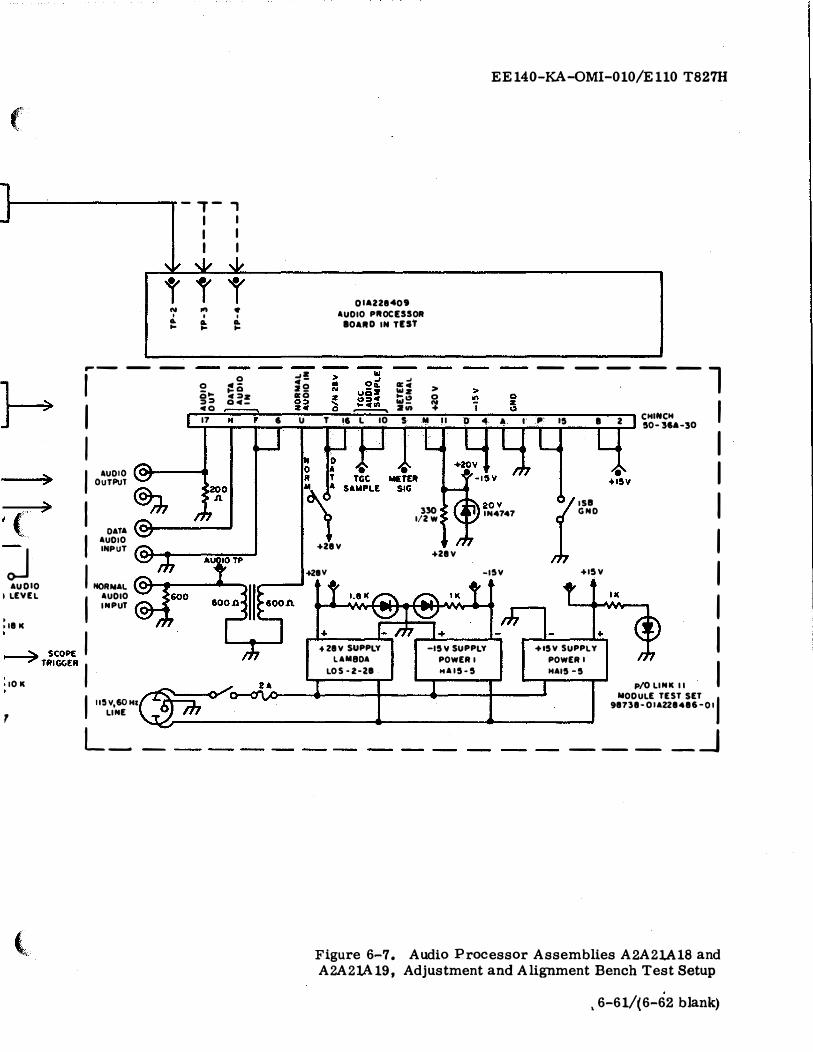
STEP
1. Preliminary Procedure for Normal Mode Adjust-ment and Alignment
2. Threshold Voltage Alignment
6-60
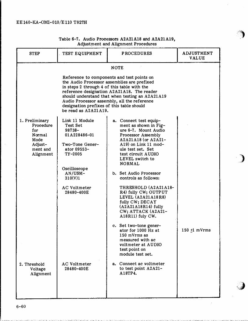
Table 6-7. Audio Processors A2A21A18 and A2A21Al9, Adjustment and Alignment Procedures
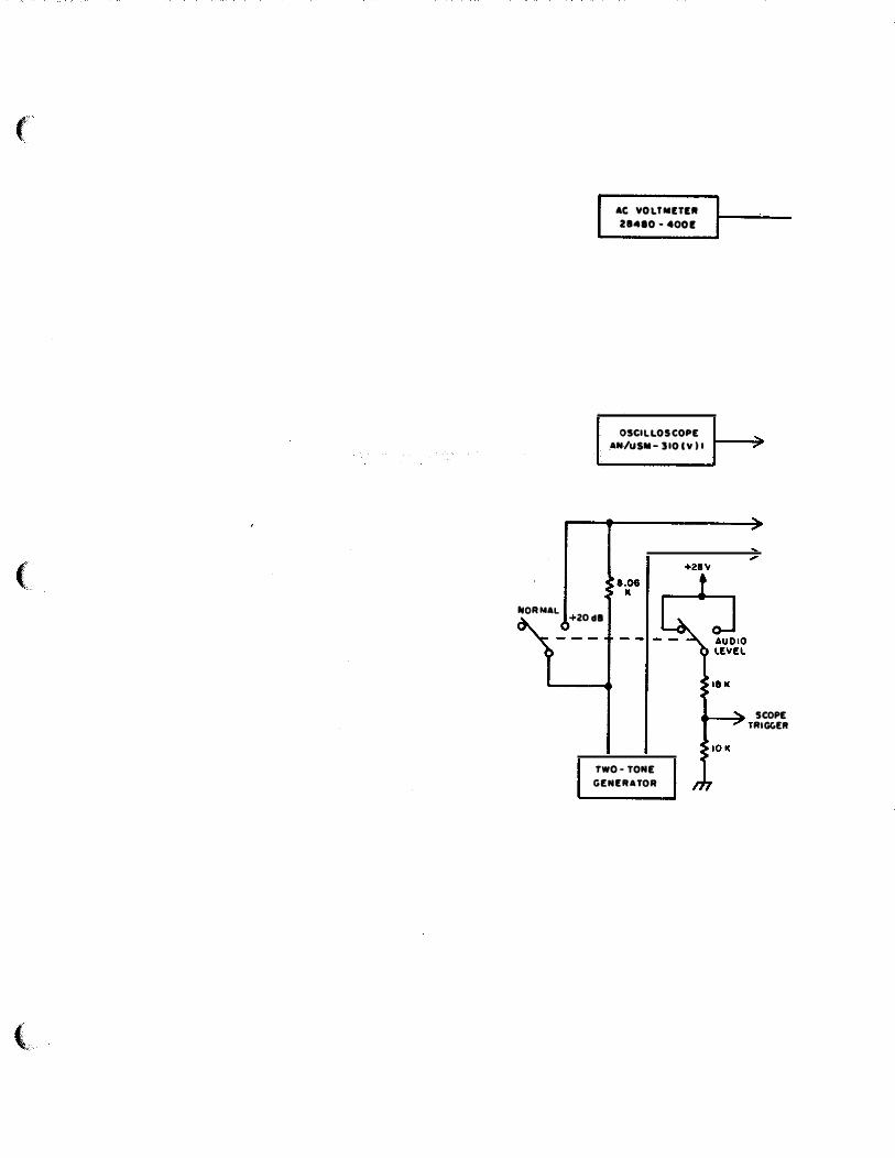
TEST EQUIPMENT PROCEDURES
NO TE
Reference to components and test points on the Audio Processor assemblies are prefixed in steps 2 through 4 of this table with the reference designation A2A21A18. The reader should understand that when testing an A2A21A19 Audio Processor assembly, all the reference designation prefixes of this table should be read as A2A21A19.
Link 11 Module a. Connect test equip-Test Set ment as shown in Fig-98738- ure 6-7. Mount Audio 01A228486-01 Processor Assembly
A2A21A18 ( or A2A21-Two-Tone Gener- A19) on Link 11 mod-
ator 09553- ule test set. Set TF-2005 test circuit AUDIO
LEVEL switch to NORMAL
Oscilloscope AN/USM- b. Set Audio Processor 310(V)l controls as follows:
AC Voltmeter THRESH OLD (A2A21A18-28480-400E R4) fully CW; OUTPUT
LEVEL (A2A21A18R8) fully CW; DECAY (A2A21A18Rl4) fully CW; ATTACK (A2A21-A18Rll) fuly CW.
c. Set two-tone gener-ator for 1000 Hz at 150 mVrms as measured with ac voltmeter at AUDIO test point on module test set.
AC Voltmeter a. Connect ac voltmeter 28480-400E to test point A2A21-
A18TP4.
ADJUSTMENT VALUE
150 !1 mVrms
I I
''· ·····.,
)
YJ
...
. "'
o
...
0
; ..
..
..
-'o
o
.
>
..
u•
..
...
-w
Q.
>
o
u
o
.,-
o"'
_,
,
...
-
���
��
O
z
c.
>
•
�
•
...
0 N
_,
c
2
a:
0 z
+
wll:
Q.
W
0� u
_
IIIII:
..
.
..,a:
z
e 0
c
..
. II:
.
..,
Oz
.
..
. t-
u
EE140-KA-0MI-010/E110 T827H
( -
- , -, -
""
r N I Q. ..
I .-- --
~
�( J AUDIO
..... 7
...... 7
1 I I I AUDIO
OUTPuT
I DATA
I AUDIO INPUT
: LEVEL
I oi81C
I NORMAL AUDIO
INPUT
� SCOPE I � TRIGGER I •IO K
7
(
I II!IV,60H& LINE
L __
I I I I I I
"" .J,
r r .., • I I
IL Q. .. ..
--0
2 j!Ci o .. 4�z �� 04-
_,a 4 -22 11:0
OIA228409 A UDIO PltOCESSOR
80Ait0 IN TIES'I'
... 11:4 > � z
o ���� N
- -- -- 1 23 40 ....-----. , -- - � 2vt + -
CHINCH I I I
17 H .. I : � : :; T 16 L 10 s M II 0 4 .. I .. 15 • 2 I 50-364-30 I I I I I l i i l i i l i i l l i l I I
�01 I
0 :A T
IM AA �
+28V t!··· 3:S0 IN4747 I/2W
+28V
+ZSV -I !IV
+Z8V SUPPLY -15Y SUPPLY
LAMBDA POWER I LO S•Z·28 HAI5•5
GND
I ... +ISV
+15V SUPPLY
POWER I HAI5 -5
+
I I I I I I p/0 LINK I I
NODULE TEST SET 98738·01AZZ8486-0J I
_ ___ _j
Figure 6-7. Audio Processor Assemblies A2A21Al8 and A2A21Al9, Adjustment and Alignment Bench Test Setup
, 6-61/(6-62 b1ank)
'-··
(
STEP
2. Threshold Voltage Alignment (Cont.)
(
3. Attack Time Adjustment
(
·�--�-
EE 140-KA-OMI-010/E 110 T827H
Table 6-7. Audio Processors A2A21A18 and A2A21A19, Adjustment and Alignment Procedures (Continued)
TEST EQUIPMENT PROCEDURES
Two-Tone Gener- b. Adjust OUTPUT ator 09553- LEVEL control TF-2005 A2A21A18R8 CCW
until ac voltmeter indicates 100 mVrms.
c. Adjust THRESHOLD LEVEL control A2A21-A18R4 CCW until ac voltmeter indicates 80 m Vrms, then adjust clockwise slowly for 100 ±2 mVrms indica-tion.
d. Set test circuit AUDIO LEVEL switch to +20 dB. Adjust OUTPUT LEVEL control A2A21A18R8 CCW for 134 !2 mY rms indication on true rms voltmeter.
NOTE
Repeat steps c. and d., trimming the adjust-ment of A2A21A18R4 and A2A21A18R8 as neces-sary to obtain correct output for both po-sitions of the AUDIO LEVEL switch.
Oscilloscope, a. Set ATTACK control Storage A2A21A18Rll approxi-AN/USM- mately five (5) turns 310(V)1 CCW, set test circuit
AUDIO LEVEL switch at Two-Tone Gener- NORMAL, and set two-
ator 09533- tone generator for TF-2005 1000 Hz at 150 mY rms.
AC Voltmeter 28480-400E
ADJUSTMENT VALUE
100 mVrms
100 mVrms
134 ±2 mVrms
150 mY rms
6-63
EE 140-KA-OMI-0 10/E 110 T827H
STEP
3. Attack
6-64
Time Adjustment (Cont.)
Table 6-7. Audio Processors A2A21A18 and A2A21A19, Adjustment and Alignment Procedures (Continued)
TEST EQUIPMENT PROCEDURES
b. Set test circuit AUDIO LEVEL switch to +20 dB. Set oscilloscope controls for- de trigger, 10 ms/cm sweep, and 3
em p-p vertical deflection with recurrent sweep.
c. Set test circuit AUDIO LEVEL switch to NORMAL. Set oscilloscope for Single Sweep, External Trigger and storage mode.
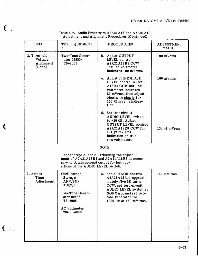
d. Wait at least 10 seconds and set test circuit AUDIO LEVEL switch to +20 dB. Attack time as illustrated in Waveform A shall be 35 to 45 ms.
NOTE
To measure attack time, set test circuit AUDIO LEVEL switch to NORMAL and allow at least 10 seconds before setting it to +20 dB.
e. If the attack time measured in step d. is not 35 to 45 ms, adjust ATTACK control A2A21A18Rll slightly CCW to decrease (or C W to increase) attack time.
ADJUSTMENT VALUE
MEASURE TO POINT WHERE SIGNAL AMPLITUDE EQUALS 4 DIVISIONS.
,+, :,
)
,,,)
(
STEP
3. Attack Time Adjustment (Cont.)
4. Decay Time Adjustment
(
(
EE140-KA-OMI-010/E110 T827H
Table 6-7. Audio Processors A2A21A18 and A2A21A19, Adjustment and Alignment Procedures (Continued)
TEST EQUIPMENT PROCEDURES
f. Repeat steps c., d. and e. until attack time is 35 to 45 ms.
g. Set test circuit AUDIO LEVEL switch to +20 dB and ad-just OUTPU T LEVEL control A2A21A18R8 as necessary to ob-tain 134 ±2 mVrms indication at A2A21-Al8TP4.
Same as a. Set test circuit Step 3. AUDIO LEVEL switch
to NORMAL. Set oscilloscope con-trols for -de trigger, 9.5 sec/ em sweep, and 6.4 em p-p vertical deflec-tion with recurrent sweep.
b. Set DECAY control A2A21A18R14 approxi-mately 5 turns CW.
c. Set test circuit AUDIO LEVEL switch to +20 dB. Set oscilloscope for single sweep, Ex-ternal Trigger and storage mode.
ADJUSTMENT VALUE
35 to 45 ms. I
134 ±2 mVrms.
6-65
EE 140-KA-OMI-010/E 110 T827H
STEP
4. Decay
6-66
Time Adjustment (Cont).
Table 6-7. Audio Processors A2A21A18 and A2A21A19, Adjustment �nd Alignment Procedures (Continued)
TEST EQUIPMENT PROCEDURES ADJUST MENT VALUE
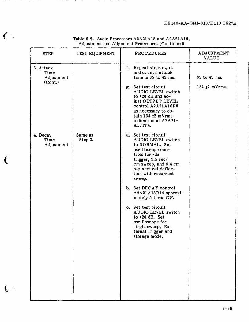
d. Wait at least 10 1 DECAY TIME wAVEFORM a
seconds and set test circuit AUDIO LEVEL switch to NORMAL. Decay time as illustrated in Waveform B shall be 1.65 to 1.85 sec.
NOTE
To measure decay time, set test circuit AUDIO LEVEL switch to +20 dB and allow at least 10 seconds before setting it to NORMAL.
e. If the decay time measured in step d. is not 1.65 to 1.85 seconds, adjust DECAY control A2-A21A18R14 slightly CW to increase (or CCW to decrease) decay time.
f. Repeat steps c., d. and e., until decay time is 1.65 to 1.85 seconds.
g. Set test circuit AUDIO LEVEL switch to +20 dB and adjust OU TPUT LEVEL control A2A21A18R8 as
necessary to obtain 134 ±2 mVrms indication at A2A21A18-TP4.
h. Recheck Step 2.
MEASURE TO POINT WHERE SIGNAL AMPLITUDE EQUALS 4DIVISIONS.
1.65 to 1.85 sec.
134 ±2 mVrms.
"*)
'") 0 ,,, '·
i;)
(
STEP
5. Preliminary Procedure for Data Mode Adjustment and Alignment
(
(
'
EE 140-KA-OMI- 010/E 110 T827H
Table 6-7. Audio Processors A2A21A18 and A2A21Al9, Adjustment and Alignment Procedures (Continued)
TEST EQUIPMENT PROCEDURES
NOTE
All actions performed at T-827H/URT unless otherwise noted.
a. Disconnect cable W5, if used, from con-nector lA2AlJ6 on rear of AM-3924C(P)/URT to prevent coupler con-trol from requesting tune power. If the AN/URA-38( ) is used and cable W5 cannot be disconnected from con-nector 1A2A1J6, set the C-3698( )/URA-38 mode selector switch to MANUAL and ensure that the variable tuning elements are set away from the home and far end stop positions.
b. Set T-827H/URT controls as follows: mode selec-tor switch: OFF LOCAL/RE-MOTE switch: REMOTE LSB and USB line level switches: -10 DB DATA/NOR-MAL switch: NORMAL F requency controls: 4.5550
MHz
---- -------- -------------- �-----------
ADJUSTMENT VALUE
-- --6-67
EE140-KA-OMI-010/E110 T827H
I
STEP
5. Preliminary Setup Pro-cedures for Data Mode Ad-justment and Alignment (Cont.)
6. USB AF Amplifier Gain Ad-justment -Data Mode
6-68
Table 6-7. Audio Processors A2A21A18 and A2A21A19, Adjustment and Alignment Procedures (Continued)
TEST EQUIPMENT
Two-Tone Gener-ator 09553-TF-2005
AC Voltmeter 28480-400E
Oscilloscope AN/USM-281
-
-
PROCEDURES
c. Set AM-3924C(P)/URT controls as follows:
PRIMARY P OWER switch: OFF
FREQUENCY MHz switch: AUTQ-
MATIC
LOCAL/TUNE KEY switch: NORMAL
PWR control: Fully CCW
Multipurpose meter func-tion switch: PA PLATE
a. Connect two-tone gener-ator to the T-827H/URT DATA AUDIO IN connect-or 3A1A1J8, pins A and B. Set the T-827H/URT mode selector switch to USB. Adjust the two-tone generator output for 1300 Hz at 1.05 Vrms (+2.6 dBm).
b. Connect the ac voltmeter to A2A21A18TP2. Adjust DATA AUD IO Control A2A21A18R33 for 1.05 Vrms.
c. Adjust the two-tone generator for two tones: Tone A for 1300 Hz and Tone B for 1600 Hz. E ach tone amplitude is adjusted for 1.05 Vrms (+2.6 dBm).
------------------
'?)
ADJUSTMENT VALUE
)
,,.),, ... .. �,-
(
STEP
6. USB AF Amplifier Gain Ad-justment -Data Mode (Cont.)
(
LSB AF Amplifier Gain Ad-justment -Data Mode
(
EE 140-KA-OMI-010/E110 T827H
Table 6-7. Audio Processors A2A21Al8 and A2A21Al9, Adjustment and Alignment Procedures (Continued)
TEST EQUIPMENT PROCEDURES
d. Connect the oscilloscope to USB Audio Amplifier test point A2A21A18-TP3. Adjust the oscil-loscope controls to measure a 9V peak to peak (P-P) two-tone waveform.
e. Adjust the CLIP LEVEL control A2A21A18R26 for a 9 V P-P two-tone audio waveform. The maximum peaks of the two-tone waveform may appear slightly flat indicat-ing clipping action.
f. Connect the ac voltmeter to USB Audio Amplifier test point 3A2A21A18TP4. The voltage should measure 50 to 100 mVrms.
g. Disconnect the ac volt-meter and the oscillo-scope from the USB Audio Amplifier test points.
h. Connect two-tone gener-ator to the T-827H/URT DATA AUDIO IN connector 3A1A1J8, pins C and D. Set the T-827H/URT mode selector switch A2S2 to LSB. Adjust the two-tone generator output for 1300 Hz at 1.05 Vrms (+2.6 dBm).
ADJUSTMENT VALUE
6-69
EE 140-KA-OMI-010/E 110 T827H
STEP
LSB AF Amplifier Gain Ad-justment -Data Mode (Cont.)
6-70
Table 6-7. Audio Processors A2A21A18 and A2A21A19, Adjustment and Alignment Procedures (Continued)
TEST EQUIPMENT PROCEDURES
i. Connect the ac voltmeter to A2A21A19TP2. Adjust DATA AUD IO control A2A21A�9R33 for 1.05 Vrms. -
j. Adjust the two-tone generator for two-tones; Tone A for 1300 Hz and Tone B for 1600 Hz.
Each tone amplitude is adjusted for 1.05 Vrms (+2.6 dBm).
k. Connect the oscilloscope to LSB Audio Amplifier test point A2A21A19TP3. Adjust the oscilloscope control to measure a 9V peak to peak (P-P) two-tone waveform.
1. Adjust the CLIP LEVEL control A2A21A19R26 for a 9 V P-P two-tone audio waveform. The maximum peaks of the two-tone waveform may appear slightly flat, indicat-ing clipping action.
m. Connect the ac voltmeter to USB Audio Amplifier test point 3A2A21A19-TP4. The voltage should measure 50 to 100 mVrms.
'��
ADJUSTMENT VALUE
)
'�JJ
(
STEP
LSB AF Amplifier Gain Ad-justment -Data Mode (Cont.)
(
{
EE 140-KA-OMI-010/E 110 T827H
Table 6-7. Audio Processors A2A21A18 and A2A21Al9, Adjustment and Alignment Procedures (Continued)
TEST EQUIPMENT PROCEDURES
n. Disconnect the ac volt-meter and the oscillo-scope from the LSB Audio Amplifier test points. Disconnect the two-tone generator from connector 3AlA1J8. Reconnect cable W5, if used, to AM-3924C/URT rear case connector 1A2AlJ6.
ADJUSTMENT VALUE
6-71
EE 140-KA-OMI-010/E 110 T827H
SECTION II
REPAIR
WARNING
Lethal voltages are present within the T-827H/URT chassis. Determine that equipment is fully deenergized, and that primary power is secured at the bulkhead distribution point. Refer to NAVSHIPS 0967-LP-000-0100, Section III, Electronic Installation Maintenance Book - General, before continuing.
6-12. GENERAL.
6-13. This section contains instructions for the repair of assemblies and subassemblies of Radio Transmitter T-827H/URT. Instructions include remove!, disassembly, inspection, replacement of parts, cleaning, reinstallation, adjustment, and checkout. Where applicable, illustrations in Chapter 7 are referenced for parts locations.
NOTE
The following assemblies are to be repaired at depot only: Mode Selector A2A1, RF Amplifier A2A4, Frequency Standard A2A5, Translator/Synthesizer A2A6, RATT Tone Generator A2A9, IF Amplifier A2A12, Audio Processors A2A21A18 and A2A21A19, and Audio Control A2A21A20.
6-14. INSPECTION. Inspect removed assemblies, subassemblies and parts in accordance with the criteria listed in table 6-8.
6-15. REPAIR METH ODS. After a malfunction has been traced to a specific assembly or subassembly, repair can, in most instances, be effected by replacement of the defective component part. Disassembly shall be only to the extent required for access to the part to be replaced.
6-16. WIRE, CABLE, AND CONNECTORS. RF Connectors on assemblies A2A1, A2A4, A2A5, A2A6 and A2A12, associated mating connectors on the main frame, and main frame connectors A1P2 and A2J22 are repairable. Repair of these connectors consists of removal and replacement of the
6-72
rf inserts. Connectors within the Translator /Synthesizer are repairable only to the extent that rf inserts are replaceable. To repair a connector, proceed as follows:
1. To replace a connector rf insert (crimp type) on flexible coax:
a. Using extractor tool 91146-CETC6B, remove rf insert from the connector.
b. Cut coaxial cable as close as possible to shell of rf insert; it may be necessary to cut through cable marker.
c. Prepare the cable for insertion into a new rf insert by removing 7/16 inch of the outer jacket, cutting the shields 1/4 inch from the center conductor, and tinning the center conductor.
d. Slip the metal sleeve (part of the rf insert) over the cable.
e. Insert the center conductor into the tube of the rf insert until the stripped portion rests in the channel at the center of the insert. Solder center conductor into place using SN60WRMAP solder.
NOTE
It may be necessary to flare the ends of the shields to permit them to slide over the outside of the tube.
f. Solder the metal cap (part of the rf insert) into place.
g. Slide the metal sleeve toward the body of the rf insert as far as possible. The braided shields will then be held in place around the tube by the sleeve.
h. Crimp the sleeve using M22910/7-1 tool with 80920-612971 die.
2. To replace a connector rf insert (solder type) on flexible cable:
'")-
�>
J' ·:,�
('
ITEM
Case
External connectors
Internal cabling and wiring
Ora wer slides
(
Front panel
Main frame, top
Main frame, bottom
(
EE 140-KA-QMI-010/E 110 T827H
Table 6-8. Inspection Requirements for Radio Transmitter T-827H/URT
CHECK FOR CORRECTIVE ACTION
Case Al
Cracks Replace case.
Dents Replace case if dents are large. Small dents can be hammered out after removing chassis.
Chipped paint, Touch up interior with lusterless enamel, interior and color black No. 37038 of FED-STD-595. exterior Allow 8 hours drying time. Touch up
exterior with gray semi-gloss enamel per MIL-E-15090, Class 2, Type III.
Cracks; bent or Replace cracked connector. missing pins Straighten bent pins.
Broken conductors; Replace defective cables. scraped insulation
Bends; loose or Replace bent slide. Tighten loose missing hardware hardware. Replace missing hardware.
Main Frame A2
Cracked or loose Replace cracked knobs. control knobs Tighten loose knobs.
Jack cover springs Replace jack cover assembly if spring broken.
Cracked plug-in Replace. connectors
Broken or loose Replace if damaged. Tighten if loose. tuning couplers
Broken wires Replace.
Loose tuning Tighten per paragraph 6-10. drive chains
Worn tuning Replace. drive chains
Worn gears; gears Replace. with broken or bent teeth
6-73
EE 140-KA-OMI-010/E 110 T827H
ITEM
Main Frame, bottom (Cont.)
Assemblies
6-74
I
Table 6-8. Inspection Requirements for Radio Transmitter T-827H/URT (Continued)
CHECK FOR
Main Frame A2 (Cont.)
Loose screws and hardware on gear assemblies
Loose screws and hardware on plugin connectors
Bent or broken detent springs on dual and triple sprocket assemblies
Leaking electrolytic capacitors
Burned components
CORRECTIVE ACTION
Tighten.
Tighten.
Replace.
Replace.
Determine cause, correct fault, and replace.
NOTE
All T-827H/URT plug-in assemblies are designated as depot repairable. Organizational level corrective action is limited to replacement of t he defective plug-in assembly.
Damaged connectors 1 Straighten pins. Replace if necessary.
Dented dust I
Straighten if possible, otherwise covers replace.
Burned components I Determine cause, correct fault, and replace.
Leaking electro- I Replace. lytic capacitors
Damaged printed Replace printed wiring board wiring boards assembly.
Damaged printed Repair per paragraph 6-17. conductors
I
Broken or loose I Replace or repair as required. internal wiring
,�)
:)
I �)
(
ITEM
Assemblies
(
( �----�---------·-· --------�
EE140-KA-OMI-010/E110 T827H
Table 6-8. Inspection Requirements for Radio Transmitter T-827H/URT (Continued)
CHECK FOR CORRECTIVE ACTION
Main Frame A2 (Cont.)
Loose or missing Tighten or replace, as required. hardware
Broken or loose Replace if damaged. Tighten if tuning couplers loose. (A2A4 and A2A6 only)
-- ----- -------------6-75
EE140-KA-OMI-010/E110 T827H
a. Perform steps 1a. through 1g. above.
b. Solder the sleeve to the body of the insert, using SN60WRMAP solder and a 42 watt iron. Be sure that solder enters the hole in the sleeve to achieve a solder joint between the sleeve and the cable shield.
3. To replace a connector RF insert on semi-rigid coax:
a. Using extractor tool 91146-CETC6B, remove the RF inserts from connectors at both ends of the cable.
b. With a sharp knife cut off the heat shrink marker from the end of the coax undergoing repair.
c. Remove the end cover from the connector by melting the solder, wicking or sucking the solder out and lifting the edge of the cover with the point of sharp knife.
d. Remove the solder from the connection of the coax center wire to the connector center pin.
e. Heat the connection between the coax shield and the connector and withdraw the coax.
f. Slip a new piece of heat shrink tubing over the end of the coax and push the coax into the new connector insert.
g. Rotate the insert to the proper orientation and solder the center wire, the coax shield, and the end cover, respectively, to the insert.
h. Slide the new tubing into position and shrink in place.
6-17. PRINTED WIRING CONDUCTORS. Cracked or broken conductors on printed wiring boards are repairable. To repair, proceed as follows:
1. Remove the coating (if present) from conductor a distance of about 1/4 inch either side of the break, using a 42 -watt chisel tip soldering iron. The heat of the soldering iron will soften the coating to facilitate removal.
2. When coating has been removed, clean the conductor by scraping with a sharp blade.
3. Tin the cleaned section using SN60WRMAP solder.
4. Lay a piece of bare solid copper wire AWG 20 (smaller, if necessary) about 1/2 inch long on the tinned conductor, and solder into place with SN60WRMAP solder.
5. Coat the repaired section with
6-76
protective coating type ER per MIL-1-46048 if repairing a coated board.
6-18. COMPONENT REPLACEMENT. To remove and replace a component on a printed circuit board, proceed as follows:
1. Cut component leads close to printed circuit board.
2. Remove component; do not force component from printed circuit board. If necessary, use a 42 watt (maximum) soldering iron to soften coating around component sufficiently to enable removal of component.
3. Unsolder cut leads from printed circuit board using a solder wick or a solder sucker.
4. Install new component on printed circuit board and solder in place with SN60WRMAP solder using heat sinks on component leads.
5. Coat Component and immediate area around component with protective coating type ER per MIL-1-46058 if repairing a coated board.
6-19. CLEANING. After removing covers from assemblies, clean the interiors with a stream of dry air not exceeding 15 psig. The main frame and hard wired assemblies attached thereto may be cleaned in the same manner. Contact pins on connectors and vacuum tubes may be cleaned with trichloroethane per Federal Specification 0-T-620. Apply with a soft brush or lint-free cloth. Allow cleaned parts to dry in a dust free location.
6-20. TRANSMITTER CASE Al.
6-21. GENERAL. Repair of Transmitter Case Al is accomplished at organizational level.
6-22 . REMOVAL. Main Frame A2 must be removed from the case for access to the interior of the case. To remove the main frame from the case, proceed as follows:
1. Set mode selector switch A2S2 to OFF, and disable primary power at bulkhead distribution point.
''. ,
)
, ... ," <vu#
(
(
(
CAUTION
Hand guide cable at rear of main frame over front edge of case when tilting chassis to vertical position.
2. Loosen front panel screws and pull main frame forward. Release latches and tilt main frame upward to expose bottom.
3. Remove attaching hardware (including cable harness clamp A2MP84, figure 7-4B) and disconnect AlPl/ A1P2 from A2J21 I A2J22.
4. Return main frame to horizontal position.
5. Release right and left forward limiters on drawer slides and pull main frame forward about one inch.
CAUTION
Main frame weighs approximately 70 pounds. Be prepared to handle this weight before pulling main frame free of case.
6. Pull main frame forward until clear of case and drawer slides and place on bench.
6-23. DISASSEMBLY. After the main frame has been removed, further disassembly of the case is not required since all parts are accessible for replacement. If the Filter Box Assembly AlAl requires removal for replacement of ·a capacitor, remove external cables and disconnect external hardware which fastens connectors A1A1J3, A1A1J4, AlA1J5, A1A1J6, A1A1J7, A1A1J8, AlA1J23, A1A1J24 and A1A1J25 to the case. Remove hardware securing three cable clamps to the rear of the case and the two rearmost cable clamps on the side of the case. Remove hardware securing one cable clamp to the top of the case. Remove eight nuts, lockwashers and flat washers securing the metal cable guide to the top of the case and remove the cable guide. Pull the filter box forward as necessary for accessability. Remove fourteen flathead screws securing cover to the filter box and lift away cover.
6-24. INSPECTION. In addition to the inspection criteria listed in table 6-8, inspect the case for dents and check drawer slides for smooth operation.
EE140-KA-OMI-010/E110 T827H
6-25. REPAIR. Repair is accomplished by replacement of defective parts. After replacing interlock switch A1S2, connect an ohmmeter to the switch terminals and observe the ohmmeter for indication of proper opening and closing while operating the interlock plunger. Adjust the switch position if necessary.
6-26. CLEANING. Clean the interior of the case by the applicable methods of paragraph 6-19.
6-27. REASSEMBLY AND INSTALLATION. Reassembly of the filter box and cable/connector hardware is accomplished by following the procedures of paragraph 6-23 in reverse order. To install Main Frame A2 in the case, proceed as follows:
1. Mate the chassis sections of the drawer slides with the cabinet sections, and push main frame toward the case until limiters engage.
2. Release latches and tilt Main Frame A2 90 degrees to expose bottom.
3. Connect A1P1/ AlP2 to A2J21/ A2J22. Fasten connectors with hardware removed at disassembly.
4. Return main frame to horizontal position and slide into case. Fasten with front panel screws.
6-28. ADJUSTMENT. No adjustment is required other than proper positioning of interlock switch A2S2 (paragraph 6-25).
6-29. CHECKOUT. Reconnect any external cabling disconnected during disassembly and perform the maintenance turn-on procedures of table 5-5.
6-30. TRANSMITTER MAIN FRAME A2 AND HARD WIRED ASSEMBLIES.
6-31. GENERAL. The Main Frame A2 and its hard wired assemblies are repairable at organizational level. If necessary to remove a plug-in assembly for access to a connector or mechanical part, such as tuning couplers, refer to the paragraph(s) describing removal of the specific assembly(ies).
6-32. REMOVAL. Generally, repairs to the Main Frame A2 can be made by withdrawing A2 from the Case A1 on the drawer slides
6-77
EE 140-KA-OMI-010/E 110 T827H
and tilting A2 90 degrees upward to expose the bottom or downward to expose the top, as required. However, if necessary to remove A2 from Al, perform removal procedures given in paragraph 6-22.
6-33. DISASSEMBLY. Disassembly of the Main Frame A2 consists of removal of plugin assemblies, removal of hard wired assemblies for replacement or repair, removal of the chain drive and sprocket assemblies for replacement or repair, and removal of plugin connectors for replacement. Do not disassemble Main Frame A2 beyond the requirement of the specific repair task to be performed.
6-34. HARD WIRED ASSEMBLIES. The following hard wired assemblies are removable: Power Supply A2A8, Meter Amplifiers A2A10 and A2All, Handset Filter A2A14, IF Filter A2Al5, and Interconnect Circuit Card Assembly A2A21.
1. To remove Power Supply Assembly A2A8 (figure 1-3):
a. Set mode selector switch A2S2 to OFF, and disconnect primary power at bulkhead distribution point.
b. Loosen six captive screws on front panel and slide main frame out from case until slides lock.
CAUTION
Hand guide cable at rear of main frame over the front edge of case when tilting chassis to vertical position.
c. Release latches and tilt chassis up to expose bottom. Be sure latches engage at 90 degree position.
d. Remove four flat-head machine screws which fasten protective plate (A2MP-80, figure 7-4A) covering Power Supply Assembly A2A8, and lift protective plate from chassis.
e. Unscrew four hexagon spacers (A2MP76 through A2MP79, figure 7-4A) which hold A2A8.
f. Remove one nut which fastens ground strap lug to main frame.
g. Swing assembly aside to expose soldered leads.
6-78
h. Unsolder and tag leads for identi-fication.
i. Remove assembly from main frame.
2. To remove Meter Amplifier Assembly A2A10 or A2All (Figure 1-2):
a. Perform steps l.a and l.b, above. b. Remove bracket MP83 to expose
A10/A11. c. Remove two machine screws
which hold the assembly. d. Perform steps l.g through l.i
above. 3. To remove Handset Filter Assembly
A2A14 (figure 1-2): a. Perform steps La and l.b above. b. Remove two machine screws
from right hand side of front panel HANDSET jack.
c. Perform steps l.h and l.i, above. 4. To remove IF Filter Assembly A2A15 (figure 1-3):
a. Perform steps l.a through l.c, above.
b. Remove two machine screws which fasten printed wiring board to mounting posts (A2A15-MP1, MP2, figure 7-81).
c. Perform steps l.h and l.i, above. 5. To remove interconnect Circuit Card Assembly A2A21 (figure 1-3):
bly.
a. Perform steps 1.a and l.b above. b. Remove cover of A2A21 assem-
c. Remove circuit cards A2A21Al8, A2A21A19, and A2A21A20.
d. Remove the six screws holding connectors A2A21XA18, A2A21XA19, and A2A21XA20 to the chassis.
CAUTION
Hand guide cable at rear of main frame over the front edge of case when tilting chassis to vertical position.
e. Release latches on chassis slides, and tilt chassis up to expose bottom. Be sure latches engage at 90 degree position.
f. Unsolder and tag all leads connected to the A2A21 assembly.
g. Remove two screws holding the A2A21 assembly to the chassis.
h. Remove assembly from chassis.
')
)
")
('
(
(
6-35, TUNING CHAIN-DRIVE MECHANISM. To remove drive chains and sprocket assemblies, proceed as follows:
1. Set mode selector switch A2S2 to OFF, and disable primary power at bulkhead distribution point.
2. Loosen six captive screws on front panel and slide main frame from case until slides lock.
3. Remove RF Amplifier Assembly A2A4 (paragraph 6-58) and Translator/Synthesizer Assembly A2A6 (paragraph 6-79) from main frame.
CAUTION
Hand guide cable at rear of main frame over front edge of case when tilting main frame to vertical position.
4. Release latches and tilt main frame up to expose bottom. Be sure latches engage at 90 degree position.
5. Loosen idler block (A2MP10, A2MP11, A2MP12 of figure 7-4B) associated with the chain to be removed.
6. If the chain is metal, locate keeper clip on chain and remove clip. If chain is plastic/wire, cut through it with wire cutters.
7. Carefully remove chain from sprockets. Proceed with the following step if replacement chain will be plastic/wire. Replacement with metal chain does not require performance of step 8.
8. Remove four nuts which fasten the associated sprocket assembly (A2MP9 and/or A2MP8 of figure 7-4B) to main frame. Lift out sprocket assembly. To disassemble a sprocket assembly (figures 7-5, 7-6):
a. Remove two retaining rings located inside assembly housing and secured around shaft. ·
b. Loosen the coupler hub-clamp setscrew and punch out the shaft from end opposite coupler.
c. Separate parts of assembly as parts clear the shaft.
NOTE
Always note the position of all shims adjacent to the retaining
EE 140-KA-OMI-010/E 110 T827H
rings; shims must be reinserted in the same position at reassembly.
6-36. INSPECTION. Inspect Main Frame A2 and any removed hard wired assembly in accordance with the applicable portion of table 6-8.
6-37. REPAIR. Except for sprocket assemblies, repair is accomplished by replacement of defective parts, all of which are accessible. To repair sprocket assemblies, proceed as follows:
1. Wipe all disassembled parts with a dry, lint-free cloth.
2. Inspect all parts for damage and replace as required.
3. Replace metal springs which provide tension between associated parts.
4. If shaft is scored, replace both coupler and shaft.
5. Replace detent springs if bent. 6. Replace hub clamp if it was evident
during equipment operation that proper clamping action was not being maintained,
6-38. CLEANING. Refer to paragraph 6-19 for cleaning methods and materials. Clean removed parts and main frame before reassembly.
6-39. REASSEMBLY. Reassembly consists of installation of hard wired assemblies, sprocket assemblies, and drive chains.
6-40. HARD WIRED ASSEMBLIES. Whenever hard wired assemblies are being installed, the primary power shall be disabled at the bulkhead distribution point. For steps 1 and 4 below, it is necessary to tilt the main frame 90 degrees to expose bottom. The main frame need not be tilted for steps 2 and 3.
1. To install Power Supply Assembly A2A8 (figure 1-3):
a. Solder leads to assembly as tagged when removed.
b. Swing assembly into place and fasten with four hexagon spacers (A2MP76 through A2MP79, figure 7-4A), and secure ground strap to main frame with nut originally removed.
6- 79
EE14 0-KA -OMI-010/El10 T827H
c. Hold protective plate (A2MP80) in place and fasten into place with four flathead machine screws originally removed.
2. To install Meter Amplifier Assembly A2A10 or A2All (figure 1-2):
a. Solder leads to assembly. b. Swing assembly into place and
fasten with two machine screws originally removed.
c. Reinstall bracket MP83. 3. To install Handset Filter Assembly
A2A14 (figure 1-2): a. Solder leads to assembly. b. Swing assembly into place and
fasten with two machine screws originally removed.
4. To install IF Filter Assembly A2A15 (figure 1-3):
a. Solder leads to assembly. b. Fasten assembly into place with
hardware originally removed.
6-41. TUNING CHAIN-DRIVE MECHANISM. Proceed with the following four steps if reassembly of tuning chain-drive mechanism involves plastic/wire chain. Otherwise go to step 5.
1. When reassembling sprocket assemblies (figures 7-5, 7-6) use new retaining rings in place of those which were removed. Reinsert shims in the same positions from which removed. Install plastic-wire chain over sprockets before assembling sprocket and shaft casting.
NOTE
End play in the shafts shall be less than 0.025 inch. Add or remove shims as required.
2. Secure each sprocket assembly into position with four nuts.
3.. Pass drive chain(s) over appropriate open drive sprocket (A2MP8 and/or A2MP9) and idler sprocket (A2MP10A, A2MP11A, or A2MP12A). Refer to figure 7-4B and table 7-2 to determine which chain is appropriate for each application.
4. Adjust in accordance with paragraph 6-43. Proceed with the following steps if reassembly of tuning chain-drive mechanism involves metal chain.
5. Thread drive chain(s) onto gears.
6-80
6. Fasten ends of each chain together using keeper clip.
7. Tighten idler block loosened in step 6-35(5).
6-42. INSTALLATION. If Main Frame A2 was removed from Case A1 for repair purposes, perform paragraph 6-27 to install A2.
6-43. ADJUSTMENTS. After repairs on chain drive tuning mechanism, perform drive chain and coupler adjustments of paragraph 6-10 and 6-11. After repairs on Power Supply A2A8, perform adjustment of table 6-1, step 3. Adjustment or alignment is not required after repair and installation of the following subassemblies: Meter Amplifiers A2A10 and A2All, Handset Filter A2A14, and IF Filter A2A15.
6-44. CHECKOUT. Perform the maintenance turn-on procedures of table 5-5 to check out Radio Transmitter T827H/URT.
6-45. MODE SELECTOR ASSEMBLY A2Al.
6-46. GENERAL. Mode Selector Assembly A2A1 is repairable at depot only; organizational level repair is limited to removal and replacement of A2Al.
6-47. REMOVAL. The location of the Mode Selector Assembly A2A1 is shown in figure 1-2. To remove the assembly:
1. Set mode selector switch A2S2 to OFF position.
2. Loosen six front panel screws and pull Main Frame A2 from Case A1 until slides lock.
3. Loosen two captive screws securing A2A1 to the main frame.
4. Gently pull Mode Selector Assembly A2Al upward using captive screws as handles.
6-48. DISASSEMBLY. Disassemble Mode Selector Assembly A2A1 only to the extent necessary to gain access to a defective component requiring replacement. To disassemble A2A1 proceed as follows:
1. To remove cover (A2A1MP1, figure 7-8):
a. Remove two screws, at top of assembly, securing cover.
�)
)
(J
(
(
(
b. Lift cover off assembly. 2. To remove Balanced Modulator Subas
semblies A2A1A1 and A2A1A2, Isolation Amplifier Subassembly A2A1A3, 500 kHz Gates Subassembly A2A1A4, or Buffer Assembly A2A1A5:
a. Remove screws and associated washers securing subassembly.
b. Swing subassembly aside and note placement of all leads for reassembly. Unsolder and tag wires for identification at reassembly.
c. Lift out subassembly. 3. Removal of other parts is obvious by
visual inspection.
6-49. INSPECTION. Inspect Mode Selector Assembly A2A1 and subassemblies in accordance with the applicable portions of table 6-8.
6-50. REP AIR. Make necessary repair's in accordance with inspections given in paragraphs 6-15 through 6-18.
6-51. CLEANING. Clean parts and subassemblies of Mode Selector Assembly A2A1 in accordance with the applicable portions of paragraph 6-19.
6-52. REASSEMBLY. To reassemble Mode Selector Assembly A2A1, reverse the disassembly procedure. Be sure to dress subassembly leads in the same positions as they were before removal of the subassembly, and do not install cover until the procedures described in paragraph 6-53 have been performed.
6-53. ADJUSTMENT. Perform the adjustment and alignment procedures of table 6-2; completion of the procedures in table 6-2 satisfies the requirement for checkout.
6-54. INSTALLATION. To install Mode Selector Assembly A2A1 in Main Frame A2:
1. Turn captive screws counterclockwise until held by Mode Selector Assembly A2A1 chassis.
2. Install Mode Selector Assembly A2A1 in the main frame in the position shown in figure 1-2.
3. Press down gently on Mode Selector Assembly A2A1 to mate connectors on assembly with connectors on main frame.
EE 140-KA-OMI-010/E 110 T827H
4. Secure Mode Selector Assembly A2A1 in place with captive screws.
NOTE
After installation, adjust AM carrier amplitude and USB and LSB carrier suppression as instructed in table 6-1, step 7, and check overall performance of Radio Transmitter T-827H/URT in accordance with table 5-5.
6-55. RF AMPLIFIER ASSEMBLY A2A4.
6-56. GENERAL. Organizational repair of RF Amplifier Assembly A2A4 is limited to replacement of vacuum tubes A2A4V1 and A2A4V2, or replacement of A2A4 as a unit. Further repair and adjustment is made only at depot.
6-57. VACUUM TUBE REMOVAL AND REPLACEMENT. To remove and replace either of vacuum tubes A2A4V1 or A2A4V2 proceed as follows:
1. Set mode selector switch to OFF, loosen front panel captive screws, and extend chassis from case.
2. Reach through the slot in the RF Amplifier Assembly cover and pull the tube shield upward from the tube to be replaced.
3. Using tube puller, reach through the slot and remove the tube from its socket.
4. Hold replacement tube with pins oriented to mate with socket.
5. Insert tube through slot and push downward to seat tube properly.
6. Reinstall tube shield, slide chassis into case, and secure using front panel screws.
6-58. REMOVAL. To remove the RF Amplifier Assembly A2A4:
1. Set mode selector switch A2S2 to OFF position.
2. Loosen six front panel screws and pull Main Frame A2 from Case A1 until slides lock.
3. Loosen four captive screws, one at each corner of the assembly.
4. Lift assembly gently from the main frame using captive screws as handles.
6-81
EE 140-KA-OMI-010/E 110 T827H
6-59. DISASSEMBLY. Do not disassemble RF Amplifier Assembly A2A4 further than required for access to parts to be repaired or replaced. The major parts to be disassembled are illustrated in figures 6-8, 6-9, and 6-10. For further detailed information see figures 7-13 through 7-56 and the parts list, table 7-2. To disassemble the RF Amplifier Assembly:
1. With the assembly placed on a work bench, remove the six dust-cover screws and lift off cover (A2A4MP5, figure 7-13). Lift the white teflon ring from the slot between the top plate and top turret ring assemblies.
2. Remove the four captive screws which secure the assembly to the main frame.
3. Loosen the three screws securing the turret assembly drive motor A2A4B1 to the base. Slide motor to one side to disengage motor gear assembly from the turret drive gear. Secure motor in this position.
4. Rotate the complete turret assembly until the contacts of adjacent megahertz subassemblies are located at either side of the contacts of the outer stator contact strips attached to the rf section. One set of the three outer contact strips (identified by a small green rectangle) is located on the right of test point A2A4TP4 near the outer edge of the top plate as depicted in Figure 7-13. The actual contacts are visible under the green rectangle (as viewed obliquely through the slot .from which the teflon ring was removed). Hold the turret assembly in this position and remove the four screws securing top turret ring. Carefully lift off ring and remove all megahertz subassemblies. It may be necessary to rotate the turret slightly when removing the megahertz subassemblies near or in contact with the outer stator contacts.
5. Remove the two screws securing connector A2A4P2 to base.
6. Loosen setscrews on each of the couplers MP62 and MP63 (on bottom of base). Heat couples with heavy soldering iron to break loctite seal. Use long nose pliers at coupler hub to slide each coupler from rotor shaft.
7. Carefully remove the locating pin from each shaft. Grip with pliers. Turn and pull gently until clear.
8. Remove the three screws and washers securing the rf chassis to the base (refer to
6-82
figure 6-9). 9. Remove the screw and washer secur
ing support post to base. 10. Remove nut and washer securing
ground strap for A2A4P2A5. This is located opposite motor relay.
6-60. To remove 100/10 kHz turret assembly, rf chassis, and top plate:
CAUTION
Hold the 100/10 kHz turret assembly and rf chassis together with rubber bands to avoid damaging contacts and wafers. Do not move or separate sections until the combined sections have been placed on a workbench.
NOTE
Do not remove the turret gear assembly from the base except specifically for replacing assembly or block brushes. Each time the gear assembly is removed, the brushes are exposed to dirt as well as possible damage.
1 . While holding the base, begin lifting the top plate. When the two sections have cleared the base, lift them with both hands and place them on the bench. Note washers at shaft holes.
2. Remove the screw securing the support post to top plate and remove post.
3. Unsolder wires connecting A2A4TP3 and A2A4TP4 (ground test point). Remove the three screws securing rf chassis to top plate, and carefully separate the top plate from the rf chassis 100/10 kHz turret assembly and turret drive gear assembly. Now separate the turret drive gear assembly from the 100/10 kHz turret assembly. Carefully separate the 100/10 kHz turret assembly from inside stator strips on rf chassis.
4. To disassemble rf chassis (see figure 6-10):
a. Remove the top tube shields and tubes A2A4V1 and A2A4V2.
b. Remove three screws and washers securing RF Mixer Amplifier Subassembly A2A4A38 to rf chassis and pull A2A4A38
,"�
,)
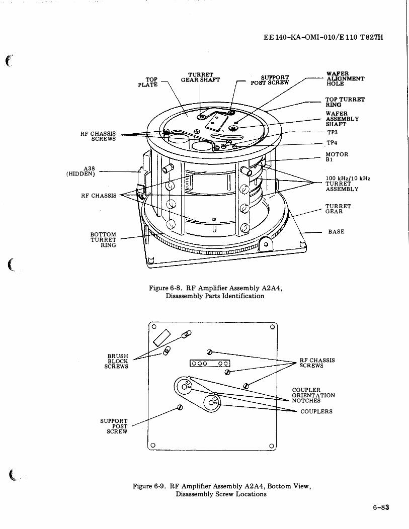
f
(
{
TOP PLATE
TURRET GEAR SHAFT
EE 140-KA-OMI-010/E 110 T827H
WAFER ----- ALIGNMENT
HOLE
TOP TURRET RING
WAFER ASSEMBLY SHAFT
RF ������ ��----- TP3
TP4
MOTOR Bl
A38 (HIDDEN)
RF CHASSIS -<= Ki'lfl I I I I f'S;;- -=='==1
100 kHz/10kHz TURRET ASSEMBLY
BOTTOM TURRET
RING
BRUSH BLOCK
SCREWS
SUPPORT POST
SCREW
TURRET GEAR
BASE
Figure 6-8. RF Amplifier Assembly A2A4, Disassembly Parts Identification
0
0
RF CHASSIS ���� '"' "',.,! � SCREWS
COUPLER ORIENTATION NOTCHES
� � COUPLERS
0
Figure 6-9. RF Amplifier Assembly A2A4, Bottom View, Disassembly Screw Locations
6-83
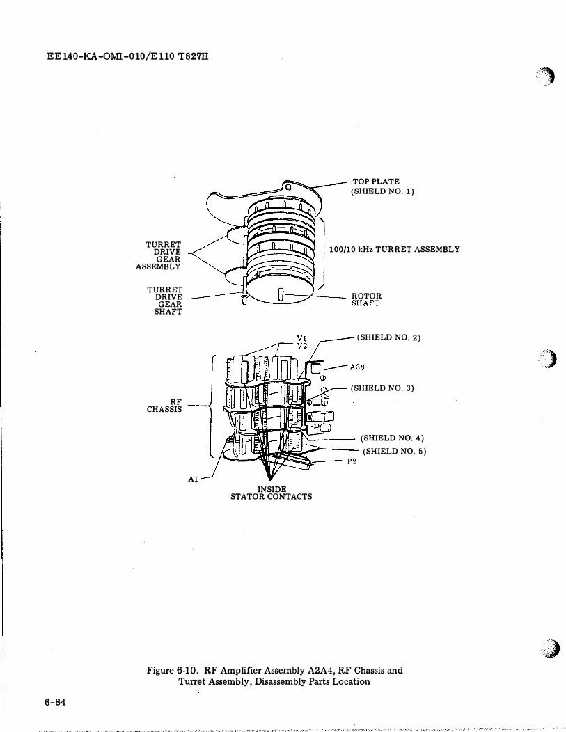
EE140-KA-OMI-010/E110 T827H
6-84
TURRET DRIVE GEAR
ASSEMBLY
TURRET DRIVE
GEAR SHAFT
RF CHASSIS
A1
TOP PLATE (SHIELD NO. 1)
100/10 kHz TURRET ASSEMBLY
I 1 ----?--- ROTOR � - SHAFT
(SHIELD NO. 2)
(SHIELD NO. 3)
(SHIELD NO. 4) � P
Z (SHIELD NO.5)
INSIDE STATOR CONTACTS
Figure 6-10. RF Amplifier Assembly A2A4, RF Chassis and Turret Assembly, Disassembly Parts Location
··�
·) .. .
(J
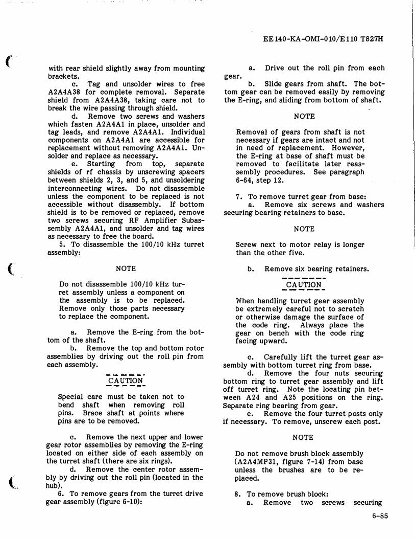
('
(
{
with rear shield slightly away from mounting brackets.
c. Tag and unsolder wires to free A2A4A38 for complete removal. Separate shield from A2A4A38, taking care not to break the wire passing through shield.
d. Remove two screws and washers which fasten A2A4Al in place, unsolder and tag leads, and remove A2A4Al. Individual components on A2A4Al are accessible for replacement without removing A2A4Al. Unsolder and replace as necessary.
e. Starting from top, separate shields of rf chassis by unscrewing spacers between shields 2, 3, and 5, and unsoldering interconnecting wires. Do not disassemble unless the component to be replaced is not accessible without disassembly. If bottom shield is to be removed or replaced, remove two screws securing RF Amplifier Subassembly A2A4Al, and unsolder and tag wires as necessary to free the board.
5. To disassemble the 100/10 kHz turret assembly:
NOTE
Do not disassemble 100/10 kHz turret assembly unless a component on the assembly is to be replaced. Remove only those parts necessary to replace the component.
a. Rem.ove the E-ring from the bottom of the shaft.
b. Remove the top and bottom rotor assemblies by driving out the roll pin from each assembly.
CAUTION
Special care must be taken not to bend shaft when removing roll pins. Brace shaft at points where pins are to be removed.
c. Remove the next upper and lower gear rotor assemblies by removing the E-ring located on either side of each assembly on the turret shaft (there are six rings).
d. Remove the center rotor assembly by driving out the roll pin (located in the hub).
6. To remove gears from the turret drive gear assembly (figure 6-10):
EE.l40-KA-0MI-010/E110 T827H
a. Drive out the roll pin from each gear.
b. Slide gears from shaft. The bottom gear can be removed easily by removing the B-ring, and sliding from bottom of shaft.
NOTE
Removal of gears from shaft is not necessary if gears are intact and not in need of replacement. However, the E-ring at base of shaft must be removed to facilitate later reassembly procedures. See paragraph 6-64, step 12.
7. To remove turret gear from base: a. Remove six screws and washers
securing bearing retainers to base.
NOTE
Screw next to motor relay is longer than the other five.
b. Remove six bearing retainers.
CAUTION
When handling turret gear assembly be extremely careful not to scratch or otherwise damage the surface of the code ring. Always place the gear on bench with the code ring facing upward.
c. Carefully lift the turret gear assembly with bottom turret ring from base.
d. Remove the four nuts securing bottom ring to turret gear assembly and lift off turret ring. Note the locating pin between A24 and A25 positions on the ring. Separate ring bearing from gear.
e. Remove the four turret posts only if necessary. To remove, unscrew each post.
NOTE
Do not remove brush block assembly (A2A4MP31, figure 7-14) from base unless the brushes are to be replaced.
8. To remove brush block: a. Remove two screws securing
6-85
EE 140-KA-OMI-010/E 110 T827H
brush block assembly to base. b. Unsolder the six code leads (five
at P1 and one at the motor relay).
6-61. INSPECTION. Inspect all disassembled parts of the RF Amplifier Assembly A2A4 in accordance with the applicable portions of table 6-8 and the following:
1. Inspect stator contact strips. Replace if badly bent and cannot be straightened to accept tabs properly.
NOTE
All contacts should close with sufficient tension to ensure proper electrical contact.
2. Inspect code ring on underside of gear assembly. Replace gear if code ring is broken or scratched to the extent that continuity is broken. To inspect code ring, rotate gear assembly while observing through brush block openings. It is not necessary to remove gear assembly from base for inspection.
3. Inspect brush blocks. Replace if contacts are badly bent or if visibly worn or chipped.
4. Inspect tube sockets. Replace damaged sockets.
6-62. REPAIR. Make necessary repairs in accordance with instructions given in paragraphs 6-15 through 6-18. Do not repair turret motor, motor relay, or tube socket assemblies if known to be defective. Replace as complete units.
6-63. CLEANING. Clean in accordance with applicable portions of paragraph 6-19. Clean all mechanical parts with a dry lintfree cloth.
6-64. REASSEMBLY. Basically, reassembly of the rf amplifier is the reverse of disassembly. See figures 6-8, 6-9, and 6-10 during reassembly. However, there are many precautions and slight variations to be observed in the reassembly process, as follows:
1. Reassemble all mechanical and electrical components of rf section except top plate; do not remount RF Mixer Amplifier Subassembly A2A4A38 at this time.
6-86
Resolder all wire connections except wires going to test points A2A4TP3 and A2A4TP4. Reinstall tubes and tube shields.
2. Reassemble 100/10 kHz turret assembly, using new E-rings where applicable. Special care must be taken not to bend the shaft when replacing the roll pin in the hub of each rotor assembly. Brace shaft near points where pins are to be reinserted. Use guide rod to align roll pin holes prior to reinserting pins. Ensure that alignment holes thru wafers and top shield are aligned on the right side of the flat on shaft when viewed from coupler end of shaft with the flat facing down.
3. Reassemble turret drive gear assembly. Do not install E-ring on shaft at this time.
4. Press ring bearing into . code ring and gear assembly. Install the four turret posts. Position bottom turret ring onto gear assembly by mating roll pin on gear assembly with hole in the bottom turret ring (hole is between megahertz assembly positions A2A4A24 and A2A4A25). Secure bottom turret ring to gear assembly. Reassemble gear assembly onto the base using the six bearing retainers.
5. Mesh 100/10 kHz turret assembly wafers with inside stator contact strips of rf chassis as follows:
CAUTION
In following steps do not spread contacts more than required to slide wire through.
a. Thread one 5 inch length of AWG 16, single-strand, insulated wire through each row of horizontal contacts on the inner stator contact strips to force contacts open slightly (in order to engage 100/10 kHz turret assembly wafers).
b. Carefully mesh wafers of the 100/10 kHz turret assembly with all contacts. The two inner stator contact strips on the upper rf chassis are not secured until the top plate is. secured. These contact strips should be positioned in a vertical plane, and then meshed with the wafers. Ensure that the shields of the rf chassis extend over the wafers, and that the grounding springs attached to shields 2, 3, and 4 are positioned on
')
)
"�
(
(
(
the top side of the 100/10 kHz turret assembly.
c. Slide the A WG-16 wires out of the contacts. Visually check that all contacts of stator contact blocks close sufficiently on wafers. Note that not all contacts are used.
6. Mesh turret drive gear assembly with gears on 100/10 kHz turret assembly. Hold the three assemblies (turret drive gear assembly, 100/10 kHz turret assembly, and rf chassis assembly) intact, and attach the top plate to the proper ends of the three assemblies. Ensure that the tabs of the upper inner stator contact strips and the outer stator contact strips are positioned within the rectangular holes in the top plate. Secure the top plate with the three original screws to the rf chassis.
7. Resolder the two wires to A2A4TP3 and A2A4TP4 (ground test point) under the top shield.
8. Align the two flat washers with the two bearings in the base. Carefully lift the assemblies and place in position on base. Set support post in position between top shield and base. Secure support post to top shield. Secure rf chassis and support post to base.
9. Reinstall locating pins into shafts of 100/10 kHz turret assembly and turret drive gear assembly.
10. Slide coupler onto 100/10 kHz turret assembly shaft. Ensure that the hub of the coupler is not beyond the bottom surface of the base. Apply loctite sealant, Grade E, per MIL-S-22473 to coupler setscrew; tighten setscrew against flat of the 100/10 kHz rotor shaft.
11. Rotate the coupler so that 0 on coupler is adjacent to, and aligned with, notch in base. Insert 4 inch, 0.125 inch diameter rod in top alignment hole on top shield. Rod should then pass through all wafers to base. If the upper or lower rotor assembly has been rotated from the position established in step 2, reposition either or both assemblies to allow the rod to pass through freely.
12. Slide coupler onto turret drive gear assembly shaft. Rotate coupler without engaging gears on 100/10 kHz turret assembly, so that 0 is adjacent to and aligned with notch in base. Push shaft up so that gears engage, and place new E-ring onto turret drive gear assembly shaft. Remove the rod. Remount RF Amplifier Assembly A2A4A38.
EE140-KA-OMI-010/E110 T827H
13. Push connector A2A4P2 through slot in base and secure to base with two screws.
14. Reattach ground strap for A2A4P2A5 on screw opposite motor relay using nut and lock washer.
15. Insert any of the 28 megahertz strips into the bottom turret ring; select a location that is not near any outer stator strip contacts. Position the top turret ring over the megahertz subassembly. Ensure that the A designation on the top turret ring corresponds to the A designation on the bottom turret r1ng. Secure the top turret ring using the four screws. Carefully rotate the turret assembly so that the megahertz subassembly contacts pass through the three sets of outer stator strip contacts. Ensure that there is an equal distance between each set of outer stator strips and the megahertz subassembly. If the dimensions are not equal, or should any interference exist between any one of the outer stator strips and the megahertz subassembly, loosen the three rf chassis screws and the support post screw. Adjust the rf chassis until the spacing is equal or the interference is eliminated. Tighten the four screws to secure the rf chassis and support post. Rotate turret assembly to break the connection between outer stator strip contacts and megahertz subassembly contacts. Remove the four screws securing the top turret ring and remove the ring. Remove the megahertz subassembly.
16. Rotate turret gear assembly until any two adjacent rectangular slots in the bottom turret ring are located at either side of the contacts on the bottom set of outer stator strips. Hold the gear assembly in this position and insert all megahertz subassemblies. (Prior to inserting the megahertz subassemblies in their respective rectangular slots, inspect all contacts to ensure that they are not bent or misaligned). Also ensure that each megahertz subassembly is in its correct location, and that it is positioned "right side up" � i.e., with transformer T4 (as shown in figures 7-20 through 7-47) adjacent to the top turret ring.
17. Position the top turret ring over the megahertz subassemblies. Ensure that the A designations on the top turret ring correspond to the A designations on the megahertz subassemblies and the A designations on the bottom turret ring. Ensure that all megahertz subassemblies are properly mated into
6-87
EE 140-KA -QMI -0 10/E 110 T827H
the rectangular slots in both the top and bottom turret ri�. Secure using the four original screws.
18. Engage gear of turret assembly drive motor with turret drive gear. Loosen screws securing turret assembly drive motor and engage the motor gear with the gear assembly. Tighten screws.
19. Place white teflon ring in slot between top plate and top turret assemblies.
20. Reattach dust cover unless adjustments are to be made.
6-65. ADJUSTMENT. Perform the adjustment and. alignment procedures of table 6-3. Completion of the procedures in table 6-3 satisfies the requirement for checkout.
6-66. INSTALLATION. To install the RF Amplifier Assembly A2A4 in Main Frame A2:
1. Set mode selector switch A2S2 to OFF, and kHz controls to 000.
2. Place RF Amplifier Assembly A2A4 in position on the main frame, and press gently into place to mate connectors and couplers.
3. Secure assembly into place with four captive screws, one at each corner.
NOTE
After installation is complete, perform step 6 of table 6-1 and check performance of Radio Transmitter T-827H/URT in accordance with table 5-5.
6-67. FREQUENCY STANDARD AS-SEMBLY A2A5.
6-68. GENERAL. Frequency Standard Assembly A2A5 is repairable at depot only. Organizational level repair is limited to removal and replacement of the assembly.
6-69� REMOVAL. The location of Frequency Standard Assembly A2A5 is shown in figure 1-2. To remove the assembly:
1. Set mode selector switch A2S2 to OFF position.
2. Loosen six screws on front panel and pull Main Frame A2 from Case A1 until slides lock.
3. Loosen two captive screws
6-88
(A2A5MP15 and A2A5MP16, figure 7-57) securing Frequency Standard Assembly to main frame.
4. Gently pull Frequency Standard Assembly upward, using captive screws as handles.
6-70. DISASSEMBLY. Disasemble the Frequency Standard Assembly only to the extent necessary to gain access to a defective component requiring replacement. To disassemble the Frequency Standard Assembly proceed as follows:
1. To remove cover (A2A5MP13, figure 7-57):
a. Remove five screws, lock washers, and flat washers which attach cover to base plate (A2A5MP1, figure 7-58) and switch bracket. Two screws are located at each side; one at the top.
b. Record position of indicator dial {A2A5MP6, figure 7-58) as seen through INDEX window.
· c. Lift cover from assembly. 2. To remove Divider/ Amplifier Subas
sembly A2A5A2 (figure 7-60): a. Remove the two nylon screws
which fasten the subassembly to the Oven Body Subassembly A2A5A3 {figure 7-61), and two screws, lock washers, and flat washers which fasten the subassembly at the bottom.
b. Unsolder and tag leads and lift out subassembly. Take care not to lose spacers (A2A5MP3, MP4, figure 7-58).
3. To remove Oven Body Subassembly A2A5A3 (figure 7"':'61):
a. Perform part a. of step 2 above. b. Remove two screws which fasten
subassembly from underside of base plate. c. Lift off subassembly with 5 MHz
Reference Control Subassembly A2A5A4 {figure 7-62) attached.
4. To remove 5 MHz Reference Control Subassembly A2A5A4 {figure 7-62):
a. Perform step 3, above. b. Remove screw, nylon washer, and
lock washer which attach subassembly A2A5A4 to Oven Body Subassembly A2A5A3.
c. Swing aside subassembly A2A5A4. Unsolder and tag leads. Lift off subassembly A2A5A4.
5. To remove Oven Body Assembly A2-A5A3 from sleeve assembly A2A5MP2 (figure 7-58):
.�,
)
... ,. ''J
(
(
(
a. Perform step 3, above. b. Remove two screws, flat washers,
and lock washers which attach oven cover assembly (A2A5MP5, figure 7-58) to sleeve.
c. Pull fine adjust knob (A2A5MP12, figure 7-57) from its shaft.
d. Lift out oven cover assembly with indicator dial (A2A5MP6, figure 7-58) attached.
e. Cut lacing cord from cable (A2-A5 W7, figure 7-60 ). Push cable into sleeve while pulling oven wiring assembly upward.
NOTE
It is not necessary to remove Oscillator and Oven Control Subassembly A2A5A1 (figure 7-59) from Oven Body Subassembly A2A5A3 for this step.
6. To remove Oscillator and Oven Control Subassembly A2A5A1 (figure 7-59):
a. Perform parts b. through d. of step 5, above.
b. Pull Oscillator and Oven Control Subassembly out of Oven Body Subassembly.
7. To remove switch A2A5A2S1 (figure 7-60):
a. Remove nut which attaches switch to bracket.
b. Unsolder and tag switch leads. Push switch downward and out.
6-71. INSPECTION. Inspect Frequency Standard Assembly A2A5 in accordance with the applicable portions of table 6-8.
6-72. REPAIR. Make necessary repairs in accordance with instructions given in paragraphs 6-15 through 6-18.
6-73. CLEANING. Clean parts and subassemblies of Frequency Standard Assembly A2A5 in accordance with applicable portions of paragraph 6-19.
6-74. REASSEMBLY. To reassemble Frequency Standard Assembly A2A5 reverse the disassembly procedure. Observe the following:
1. When inserting Oscillator and Oven Control Subassembly A2A5A1 into Oven Body Assembly A2A5A3, be sure that subassembly A2A5A1 is held in place by the nylon guides
EE140-KA-OMI-010/E110 T827H
in A2A5A3, and that the contact pins on subassembly A2A5A1 mate with the contacts of A2A5A3J1 at the bottom of the Oven Body Assembly.
2. Before reattaching the fine adjust knob to its shaft, set indicator dial to the position noted in step l.b. of paragraph 6-70.
3. Be sure to use nylon flat washer when attaching 5 MHz Reference Control Subassembly A2A5A4 to sleeve assembly A2A5MP2.
4. When attaching Oven Body Subassembly A2A5A3 with 5 MHz Reference Control Subassembly A2A5A4 to base plate, be sure contacts of A2A5A4 are properly mated with connector A2A5J3.
5. If lacing cord was removed from cable A2A5 W7, replace with new lacing. Do not install cover until paragraph 6-75 has been performed.
6-75. ADJUSTMENT. Perform the adjustment and alignment procedures of table 6-4. Performance of the procedures of table 6-4 satisfies the requirements for checkout.
6-76. INSTALLATION. To install Frequency Standard Assembly A2A5 into main frame A2:
1. Turn captive screws counterclockwise until held by base plate (A2A5MP1, figure 7-58).
2. Install Frequency Standard Assembly A2A5 in the main frame in the position shown in figure 1-2.
3. Press down gently on Frequency Standard Assembly A2A5 to mate connector on assembly with connector on main frame.
4. Secure Frequency Standard Assembly A2A5 in place with captive screws.
NOTE
After installation adjust output frequency as instructed in table 6-1, step 4, and check performance of Radio Transmitter T-827H/URT in accordance with table 5-5.
6-77. TRANSLATOR/SYNTHESIZER AS-SEMBLY A2A6.
6-78. GENERAL. Translator/Synthesizer Assembly A2A6 (figure 1-2) is repairable at
6-89
EE140-KA-OMI-010/Ell0 T827H
depot only. Organizational repair is limited to removal and replacement of the assembly.
6-79. REMOVAL. To remove Translator/Synthesizer Assembly A2A6:
1. Loosen four captive screws, one at each comer of the assembly.
2. Lift assembly gently from main frame, using two of the captive screws as handles.
6-80. DISASSEMBLY. Complete disassembly involves the removal of three covers. Do
not disassemble beyond what is required for access to the part to be repaired or replaced. To remove the top cover (A2A6-MP3, figure 7-63), remove thirteen screws and lift cover off. Removal of the top cover provides access to seven printed circuit subassemblies, A2A6A12 through A2A6A18. The plug-in subassemblies A2A6A12, A13, Al4, A16, A17, A18 may be removed by releasing their latches and pulling upward. The Power Supply Subassembly A2A6A15 can be removed by sliding it upward in its tracks and
disconnecting wires at A2A6A15E1 and A2-A6A15E4-E6 (figure 7-69). Filter Subassembly A2A6A7 (figure 7-64) is hard wired to the A2A6 chassis. To remove the Filter subassembly, first remove the Power Supply subassembly, then remove the two machine screws which fasten the Filter subassembly from the outside at the upper rear of the A2A6 housing. Lift out the Filter subassembly as far as its leads will permit. Unsolder and tag leads for identification.
6-81. TRANSLATOR SUBASSEMBLY A2-A6A8 (figure 7-65). To remove the RF Translator subassembly:
1. Remove six machine screws which attach the bottom cover (A2A6MP1, figure 7-65) and remove cover.
2. Remove six machine screws which attach the side cover and remove cover.
3. Remove thirteen screws which attach the top cover (A2A6MP3, figure 7-63) and remove cover.
4. Remove the A2A6A12 and A2A6A14 plug-in printed circuit subassemblies.
5. With the aid of rf insert extractor tool 91146-CET-C6B extract the following rf inserts which terminate the rf leads from the
6-90
RF Translator subassembly: a. A2A6A12P1A4 b. A2A6P2Al c. A2A6P2A2 d. A2A6P3A2 e. A2A6P3Al f. A2A6XA14P1A4
6. Disconnect leads at A2A6A8J4, J5, J6, J7, and also FL5-1 and FL5-J1.
7. Remove six machine screws and
washers which fasten RF Translator subas
sembly to chassis. Carefully lift out subassembly while guiding coaxial leads through slots in chassis.
6-82. ROTARY swrrcHES. To remove any of the rotary switches A2A6S1, S2, or S3 (see figure 7-63):
1. Remove thirteen screws which attach the top cover (A2A6MP3, figure 7-63) and remove cover.
2. Remove six screws which attach bottom cover to A2A6 and lift cover off.
3. Unsolder leads of flexible connector harness assembly from switch terminals.
4. Remove coupling assembly (A2A6MP8, MP12 and MP16, figure 7-63) from bottom of switch shaft.
5. Remove anti-tum washer, nut and lock was her from switch and remove switch.
6-83. MAIN CONNECTORS. To remove connectors A2A6Pl through A2A6P3, proceed as follows:
1. To remove A2A6P2 or A2A6P3 (see figure 7-63):
a. Remove coaxial inserts from connector.
b. Remove attaching hardware from connector and lift out. Take care not to damage ground wire soldered to flexible connector harness.
2. To remove A2A6Pl (see figure 7-63): a. Remove Al coaxial insert from
connector. b. Remove attaching hardware from
connector. c. Lift connector with flexible con
nector harness attached, and unsolder leads of harness.
6-84. PRINTED cmcurr BOARD CONNECTORS. To remove any printed circuit
l,
)
.. ,. ·.;;,#
(
(
'
board connector, proceed as follows:
1. Remove coaxial inserts A2A6P1Al, A2A6XA14PlA4 and A2A6XA12P1A4.
2. Remove attaching hardware from all connectors except A2A6P3.
3. Remove coaxial insert from A2 \6XA17P1A2.
4. Disconnect two power leads and one coaxial lead from FL5-1, FLS-2, and FL5-Jl respectively.
5. Remove two screws, lock washers, and flat washers securing FL5 to chassis and lift out FL5.
6. Unsolder A2A6C1 from the flex harness and lift it from its clip.
7. Unsolder flex harness from A2A6S3 (figure 7-63).
8. Eject coaxial inserts from connector to be removed. It may be necessary to eject the insert on the opposite end of the semirigid coaxial cable. Unsolder A2A6C2 and A2A6C3 from A2A6XA13P1A1 and A2A6XA13P1A2 if necessary.
9. Peel back flexible connector harness with connectors attached.
10. Unsolder connector to be replaced.
6-85. INSPECTION. Inspect Translator/Synthesizer Assembly A2A6 and its subassemblies in accordance with the applicable portions of table 6-8. Inspect the flexible connector harness for broken conductors and loose solder connections.
6-86. REP AIR. Make necessary repairs in accordance with instructions given in paragraphs 6-15 through 6-18.
6-87. CLEANING. Clean parts and subassemblies of A2A6 in accordance with the applicable portions of paragraph 6-19.
6-88. REASSEMBLY. Except for the reattachment of rotary switch couplers, reassembly is the reverse of disassembly. To attach couplers to rotary switches, align each coupler individually exactly as shown in figure 6-11.
6-89. ADJUSTMENT. Align and adjust Translator/Synthesizer Assembly in accordance with Table 6-5. Completion of procedures in table 6-5 satisfies the requirements for checkout.
EE140-KA-OMI-010/E110 T827H
6-90. INSTALLATION. To install Translator/Synthesizer Assembly A2A6 into the main frame:
1. Set frequency controls for 00.000 MHz.
2. Position couplers on rotary switches so that pins on all three are toward the rear of Translator /Synthesizer.
3. Set Translator/Synthesizer Assembly gently into place, and fasten with four corner captive screws.
4. Rotate kHz controls from 000 through 999 to check proper mating of couplers.
NOTE
After installation, slide main frame into case and fasten with front panel screws. Check performance of Radio Transmitter T-827H/URT in accordance with table 5-5.
6-91. CODE GENERATOR ASSEMBLY A2-A7.
6-92. GENERAL. Code Generator Assembly A2A 7 (figure 7-73) is repairable at depot only; organizational level repair is limited to removal and replacement of A2A 7.
6-93. REMOVAL. The location of the Code Generator Assembly is shown in figure 1-3. To remove Code Generator Assembly A2A 7 from Main Frame A2, proceed in accordance with the following:
1. Set mode selector switch A2S2 to OFF, and disaQle prirnary power at bulkhead distribution point.
2. Loosen six captive screws on front panel and slide main frame from case until slides lock.
3. Remove RF Amplifier Assembly A2A4 from main frame.
4. Looser. captive screw (A2A7MP10, figure 7-73) at rear of Code Generator Assembly.
CAUTION
Hand guide cable at rear of main frame over front edge of case when tilting main frame to vertical position.
6-91
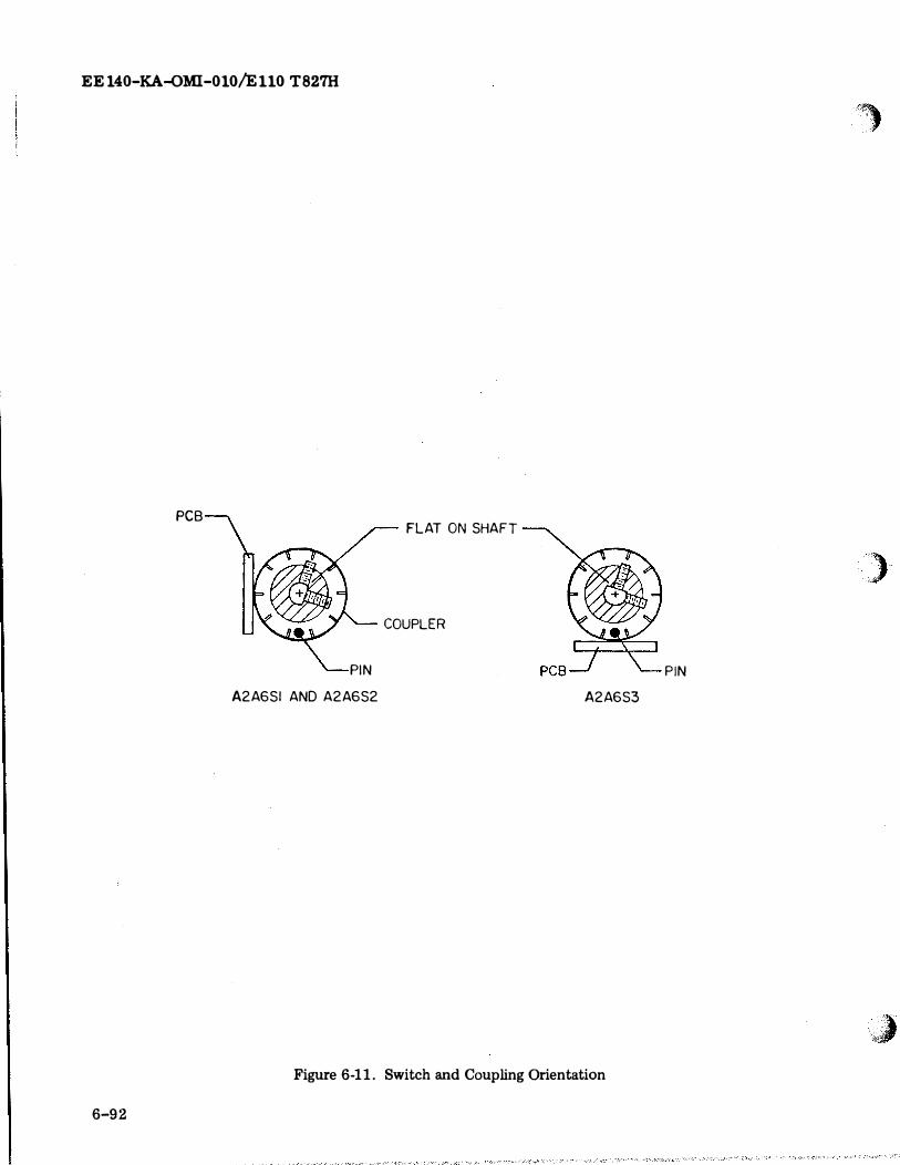
EE 140-KA-QMI-010/E 110 T827H
PCB
PIN
A2A6SI AND A2A6S2
FLAT ON SHAFT
COUPLER
A2A6S3
Figure 6-11. Switch and Coupling Orientation
6-92
P IN
,,, 'i
)-
l I
(
(
(
5. Release tilt latches and tilt main frame up to expose bottom. Be sure tilt latches engage at 90-degree position.
6. Disconnect A2A7Pl from A2J8. 7. Remove the remaining two screws
which fasten the Code Generator Assembly to the front panel mounting spacers.
8. Gently and carefully push the Code Generator Assembly toward rear of main frame to disengage its couplers from the MHz frequency controls on the front panel.
9. Carefully work the assembly out of the main frame.
6-94. DISASSEMBLY. Disassembly is accomplished by removing the screws which hold the sections of the assembly (switches A2A7Al through A2A7A5, figure 7-73) together, and unsoldering interconnections as required for access to the faulty section.
6-95. INSPECTION. Inspect the Code Generator Assembly in accordance with the applicable portions of table 6-8.
6-96. REPAIR. Repair consists of replacing printed circuit switch sections determined to be faulty by ohmmeter measurements between pins of A2A7P1 and the individual switch sections, and between sections and points on sections (see figure 5-41).
6-97. CLEANING. Refer to paragraph 6-19 for cleaning methods and materials. Clean removed parts and replacement parts before reassembly.
6-98. REASSEMBLY. Reassembly is the reverse of disassembly. Be sure to reassemble switches in correct sequence.
6-99. INSTA:CLATION AND ALIGNMENT. To install and align Code· Generator Assembly A2A 7, promred in accordance with the following:
1. Position the MHz control knobs and the couplers on the code generator so that the pins on the knob couplers will engage the slots on the switch couplers when the code generator is installed.
2. Carefully work the Code Generator Assembly into position to engage couplers.
3. Attach code generator and spacers to main frame with f!lOUnting hardw�r_� ()_t�iiJ.fJ.k·
EE 140-KA-OMI-010/E 110 T827H
ly removed or loosened. 4. Connect plug A2A7Pl to A2J8 on
main frame. 5. Set MHz controls on front panel to 07
MHz. 6. On rear of Code Generator Assembly
A2A7, note the position of the rotor contacts with respect to the gold pad contacts on the units MHz switch. Note the position of the rotor contact, relative to the gold pad contact for the 10 MHz switch, by observing the rear side edge of the center printed circuit board (below MP42 on figure 7-73). If the units MHz switch rotor contact or the 10 MHz switch rotor contact is not centered on the gold pad contact, realign using the following procedure:
a. Loosen the two flat-head cross recessed screws on detent spring A2MP16 or A2MP17 as appropriate (see figure 7-7).
b. While depressing the roller end of the spring with one finger (to keep it at the bottom of the detent wheel) rotate the frequency control knobs until the rotor contact is centered on the gold pad contact.
c. While continuing the finger pressure on the roller end of the spring, tighten the two flat-head cross recessed screws.
6-100. POWER SUPPLY ASSEMBLY A2A8.
6-101. GENERAL. Power Supply Assembly A2A8 is repairable at organizational level. Repair instructions for this hard wired assembly are supplied in paragraphs 6-15 through 6-18 and 6-34(1).
6-102. RATT TONE GENERATOR ASSEM-BLY A2A9.
6-103. GENERAL. RATT Tone Generator Assembly A2A9 is repairable at depot only. Organiza:ti"oi1ai level repair is limited to removal and replacement of the assembly.
6-104. REMOVAL. The location of RATT Tone Generator Assembly A2A9 is shown in figure 1-2. To remove the assembly:
1. Set mode selector switch A2S2 to OFF position.
2. Loosen six screws on front panel and pull Main Frame A2 from Case Al until
_slid�s.JockA
6-93
EE140-KA�MI-G10/E 110 T82'1H
3. Loosen two captive screws see� RATT Tone Generator Assembly to main frame.
4. Gently pull RATT Tone Generator A!r sembly upward, using eaptive screws as handles.
6-105. DISASSEMBLY. Disassemble the RA TT Tone Generator Assembly only to the extent necessary to gain access to a defective component requiring replacement. To disassemble the RATT Tone Generator A!r sembly proceed as follows:
1. To remove cover (A2A9MP1, figure 7-75):
a. Loosen quarter-tum screw securing cover to base.
b. Lift cover from base. 2. To remove Tone Generator Board A2-
A9A1 (figure 7-76): a. Remove five screws, lock
washers, and fiat washers which attach board to chassis base.
b. Lift out board.
6-106. INSPEC110N. Inspect RATT Tone Genertor Assembly A2A9 in accordance with the applicable portions of table 6-8.
6-107. REPAIR. Make necessary repairs in accordance with instructions given in paragraphs 6-15 through 6-18.
6-108. C LEANING. Clean parts and subassembly of RATT Tone Generator Assembly A2A9 in accordance with applicable portions of paragraph 6-19.
6-109. REASSEMBLY. To reassemble RA TT Tone Genertor Assembly A2A9 proceed as follows:
1. Drop board A2A9A1 into chassis base,
and align mounting holes with inserts. 2. Secure board A2A9A1 to chassis base
using hardware removed in paragraph 6-105, step 2.a.
3. Replace cover by engaging the tabs into the slots in the base and securing the cover with the quarter-tum screw.
6-110. INSTALLATION. To install RATI'
6-94
Tme Generator Assembly A2A9 into main frame A2:
1. Tum captive screws counterclockwise until held by chassis base.
2. Install RATT Tone Generator A!r sembly A2A9 in the main frame in the paritim shown in r:agure 1-2.
3. Press down gently on RATT Tone Generator Assembly A2A9 to mate connector on assembly with connector on main frame.
4. Secure RA TT Tone Generator Assembly A2A9 in place with captive screws.
NOTE
After installation check performance of Radio Transmitter T-827H/URT in accordance with table 5-5.
6-111. METER AMPLIFIER ASSEMBLI� A2A10 AND A2All.
6-112. GENERAL. The Meter Amplifier Assemblies A2Al0 and A2A11 are repairable at organizational leveL Repair instructions for these hard wired assemblies are supplied in paragraphs 6-15 through 6-18 and 6-34(2).
6-113. IF AMPLIFIER ASSEMBLY A2A12.
6-114. GENERAL. IF Amplifier Assembly A2A12 is repairable at depot only. Organizational level repair is limited to removal and replacement of the assembly.
6-115. REMOVAL. The location of IF Amplifier Assembly A2A12 is shown in figure 1-2. To remove the assembly:
1. Set mode selector switch A2S2 to OFF position.
2. Loosen six screws on front panel and pull Main Frame A2 from Case A1 until slides lock.
3. Loosen two captive screws securing IF Amplifier Assembly to main frame.
4. Gently pull IF Amplifier Assembly ..,ward, using eaptive screws as handles.
6-116. DISASSEMBLY. Disassemble the IF Amplifier Assembly only to the extent necessary to gain acce ss to a defective component requiring replacement. To disassemble the IF Amplifier Assembly proceed as follows:
')
)
,,J/ �.,Zi
'
(,
(,
1. To remove cover (A2A12MP1, figure 7-78):
a. Loosen turnlock fastener on cover securing cover to assembly chassis.
b. Swing top of cover approximately 1/4 inch from assembly (to allow turnlock fastener to clear assembly) and lift off.
2. If it is necessary to replace IF Amplifier Board A2A12A1 (figure 7-78) removal procedures are as follows:
a. Remove four screws and flat washers which secure board A2A12A1 to assembly chassis.
b. Lift board from assembly chassis.
6-117. INSPECTION. Inspect IF Amplifier Assembly A2A12 in accordance with the applicable portions of table 6-8.
6-118. REPAIR. Make necessary repairs in accordance with instructions given in paragraphs 6-15 through 6.;..18.
6-119. CLEANING. Clean parts and subassemblies of IF Amplifier Assembly A2A12 in accordance with applicable portions of paragraph 6-19.
6-120. REASSEMBLY. To reassemble IF Amplifier Assembly A2A12 reverse the disassembly procedure. Do not install cover until paragraph 6-121 has been performed.
6-121. ADJUSTMENT. Perform the adjustment and alignment procedures of table 6-6. Performance of the procedures of table 6-6 satisfies the requirements for checkout.
6-122. INSTALLATION. To install IF Amplifier Assembly A2A12 into main frame A2:
1. Turn captive screws counterclockwise until held by assembly base.
2. Install IF Amplifier Assembly A2Al2 in the main frame in the position shown in figure 1-2.
3. Press down gently on IF Amplifier Assembly A2A12 to mate connector on assembly with connector on main frame.
4. Secure IF Amplifier Assembly A2A12 in place with captive screws.
EE 140-KA-OMI-010/EllO T82'n.i
NOTE
After installation check performance of Radio Transmitter T-827H/URT in accordance with table 5-5.
6-123. HANDSET AND IF FILTER ASSEMBLIES A2A14 AND A2A15.
6-124. GENERAL. Handset Filter Assembly A2A14 and IF Filter Assembly A2A15 are repairable at the organizational level. Repair instructions for these hard wired a�semblies are supplied in paragraphs 6-15 through 6-18, 6-34(3), and 6-34(4).
6-125. INTERCONNECT CIRCUIT CARD ASSEMBLY A2A21.
6-126. GENERAL. Interconnect Circuit Card Assembly A2A21 is repairable at the organizational level. Repair instructions for this hard wired assembly are supplied in paragraphs 6-15 through 6-18, and 6-34(5).
6-127. AUDIO PROCESSOR ASSEMBLIES A2A21A18 AND A2A21A19 AND AUDIO CONTROL ASSEMBLY A2A21A20.
6-128. GENERAL. Audio Control Assembly A2A21A20 and Audio Processor Assemblies A2A21A18 and A2A21A19 are repairable at depot only. Organizational level repair is limited to removal and replacement of the assemblies.
6-129. REMOVAL. The locations of Audio assemblies A2A21A18, A2A21A19, and A2-A21A20 are shown in figure 1-2. To remove these assemblies:
1. Set mode selector switch A2S2 to OFF position.
2. Loosen six screws on front panel and pull Main Frame A2 from Case A1 until slides lock.
3. Loosen two quarter:..turn screws securing cover on card cage (A2MP132, figure 7-4) and remove cover.
NOTE
Mark the locations of A2A21Al8 and A2A21A19 prior to removal so
6 -95
EE140�KA-OMI-010/E110 T827H
that each assembly can later be replaced in its original location. This action will preclude unnecessary readjustment of controls when transmitter operation is resumed.
4. Lift ejectors on assembly to be re
moved, and unplug assembly.
6-130. INSPECTION. Inspect Audio assemblies A2A21A18, A2A21A19, and A2A21-A20 in accordance with the applicl.ble por-tions of table 6-8. 'i
6-131. REPAIR. Make necessary repairs in accordance with instructions given in paragraphs 6-15 through 6-18.
6-132. CLEANING. Clean Audio assemblies A2A21A18, A2A21A19, and A2A21A20 in accordance with the applicable portions of paragraph 6-19.
6-96
6-133. ADJUSTMENT. Perform the adjustment and alignment procedures of table 6-7; completion of the procedures in table 6-7 satisfies the requirement for checkout.
6-134. INSTALLATION. To install Audio assemblies A2A21Al8, A2A21A19, and A2-A21A20 in Main Frame A2:
1. Insert assembly into appropriate guides and press firmly on ejector handles until board is fully engaged in socket.
2. Replace cover on card cage by engaging the tab into the slot. Secure the cover with the two quarter-turn screws.
NOTE
After installation, perform step 5 of table 6-1 as applicable to the Audio assemblies A2A21A18, A2A21A19, and A2A21A20, and check performance of Radio Transmitter T-827H/URT in accordance with table 5-5.
:>
\ �J