Embed Size (px)
Citation preview
RADISSON BLU – SAFARI LODGE HOTEL – KRUGER NATIONAL PARK ELECTRONIC SERVICES / ICT CONCEPT DESIGN REPORT 17 January 2011
QM
Issue/revision Issue 1 Revision 1 Revision 2 Revision 3
Remarks Issue 1
Date 2011.01.17
Prepared by A. Kotzé
Signature
Checked by C. Cecchi
Signature
Authorised by C. Cecchi
Signature
Project number J5423
File reference J5423-34
Concept Design
Report
Reg. No: 1984/002074/07
Contents
1 Information and Communications Technology (ICT) 4
1.1 Cabling and IT Backbone Infrastructure 4
1.2 Internet and Communication Services 5
1.3 Incoming Telco Services 5
1.4 Telephony System 6
1.5 Active Networking Equipment 7
1.6 TV Systems 7
1.7 PMS & POS 8
1.8 Security System 8
1.9 Audio Visual, Public Address and Background Music 9
1.10 WI-FI 10
1.11 Building Management System (BMS) 10
2 Scope split to be confirmed between WSP and the Operator/Developer 13
3 Exclusions 14
3.1 Electrical 14
3.2 BUILDER'S WORK 15
3.3 PROFESSIONAL FEES 15
J5423-34 Concept Design Report 4
1 Information and Communications Technology (ICT)
1.1 CABLING AND IT BACKBONE INFRASTRUCTURE
1.1.1 Cabling
All horizontal data & telephone cabling distribution shall be of a CAT6 UTP (Unshielded Twisted Pair) structured cabling topology and be BICSI (Building Industry Consulting Services International) compliant. This shall provide the client/operator the maximum flexibility in the voice, video and data service distribution throughout the various site buildings, whereby the relevant service shall be allocated to RJ45 floor outlet connection points at the patch panel or distribution nodes interface in equipment cabinets as needed.
The telephone backbone cabling will be CAT3 indoor and UG cabling as required. This will run from the central Equipment Room (ER) in the back of house to the local TR’s per floor/block, as required.
Cat6 UTP cabling shall be provided for the IPTV System distribution as required by the individual building / block operation requirements.
All sleeves and wireways will be supplied by the Electrical Contractor.
All IT Server Rooms (incl. Redundant / back Server rooms) shall have access flooring and FM200 Inert Gas Suppression as a standard.
WSP Consulting Engineers SA (Pty) Ltd shall be responsible for the data, telephone and IT backbone cabling infrastructure.
1.1.2 Backbone
WSP propose implementing a 1GB/s Ethernet IP Network backbone infrastructure. For the OSP (Outside Plant) external fibre backbone cabling, Single Mode (SM) Fibre shall be utilised due to the extensive distances to be covered in this resort development. With SM fibre, 1Gb/s is attainable up to a maximum distance of 5km, per fibre run.
Where required (within buildings), 50/125µm MM (Multi-Mode) fibre will be used outdoors/indoors to extend the data network for cable distances in excess of 90m, as per the international CAT6 cabling standards.
All horizontal and vertical (backbone) data & telephone cabling reticulation shall be designed and installed according to the internationally accepted design standards and based on the following:
BICSI TDMM Edition 12 & IEEE 802.3 (CAT6)
ANSI/TIA/EIA-568-B
ANSI/TIA/EIA-569-B
ANSI/TIA/EIA-606-A
ANSI/TIA/EIA-758 (OSP)
To ensure manufacturing compliance, testing will be done on each fibre link and certified testing certificates will be issued by the contractor to ensure correct installation and provide a cable manufacturer warranty on the performance criteria over the fibre network. To ensure manufacturing compliance, testing will be done on each cable and certified testing certificates will be issued by the contractor to ensure correct installation and provide a cable manufacturer warranty on the CAT6 performance criteria over that cable network, for an industry standard of approximately 20 years.
J5423-34 Concept Design Report 5
The physical fibre cabling of the backbone architecture shall run in a dedicated system of underground sleeves and access manholes installed throughout the resort development, emanating from the Main Server Equipment Room (situated in the BOH) and terminating in the relevant building structures throughout the site (i.e. services plant rooms).
1.2 INTERNET AND COMMUNICATION SERVICES
WSP cannot confirm exactly what is needed until such time as the operator’s IT requirements are.
We have however made assumptions for the minimum recommended connectivity requirements for such a site, namely the following:
1.2.1 Telephony:
1 x ISDN30 (PRI) (30 lines)
8 x Analogue lines (fall-back + elevator alarms etc)
1.2.2 Data / Internet lines:
2 x 2Mb/s International Private Leased circuit (IPLC) line with QoS (quality of Service management)
2 x ADSL (2 Mb/s up/down) for redundancy and extra 3rd party service requirements.
Exact line speeds and types available shall be determined with the Telecommunications Service provider of the region and finalised during the detailed design phase.
IT convergence (voice, data and video) is becoming the standard 4th utility (just like water, electricity and gas) requirement for buildings, and as such needs to be considered as an integral part of the building infrastructure, such that modular IP based services can be provided at present or as and when required in the future.
WSP shall provide the space planning for these areas and the infrastructure to support these network system elements, including full Server Equipment Room design, incorporating elements such as Fire Gas Suppression systems, Access Flooring, Data and Cabling racks, UPS & HVAC according to international standards for Data Centre Design:
TIA942
EN 50174 Part 1 & 2
EN 50713 Part 1 to Part 5
1.3 INCOMING TELCO SERVICES
From a site telecommunications perspective the exact telephone & data service requirements are yet to be determined in conjunction with the resort operator.
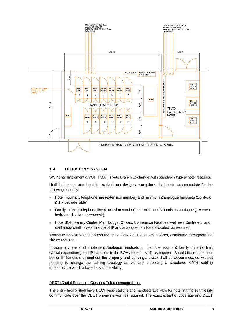
A Telco Services Termination Room shall be allocated in the BOH area of the resort which shall be sized in accordance with the local statutory requirements and shall be located next to (or in very near vicinity to) the Main Server Equipment Room. This room shall house the various service providers’ incoming lines termination equipment as well as the GSM amplification units needed to provide GSM coverage on the site.
J5423-34 Concept Design Report 6
1.4 TELEPHONY SYSTEM
WSP shall implement a VOIP PBX (Private Branch Exchange) with standard / typical hotel features.
Until further operator input is received, our design assumptions shall be to accommodate for the following capacity:
Hotel Rooms: 1 telephone line (extension number) and minimum 2 analogue handsets (1 x desk & 1 x bedside table)
Family Units: 1 telephone line (extension number) and minimum 3 handsets analogue (1 x each bedroom, 1 x living area/desk)
Hotel BOH, Family Centre, Main Lodge, Offices, Conference Facilities, wellness Centre etc. and staff areas shall have a mixture of IP and analogue handsets allocated, as required.
Analogue handsets shall access the IP network via IP gateway devices, distributed throughout the site as required.
In summary, we shall implement Analogue handsets for the hotel rooms & family units (to limit capital expenditure) and IP handsets in the BOH areas for staff, as required. Should the requirement be for IP handsets throughout the property and buildings, these shall be accommodated without needing to change the cabling topology as we are proposing a structured CAT6 cabling infrastructure which allows for such flexibility.
DECT (Digital Enhanced Cordless Telecommunications)
The entire facility shall have DECT base stations and handsets available for hotel staff to seamlessly communicate over the DECT phone network as required. The exact extent of coverage and DECT
J5423-34 Concept Design Report 7
requirements shall be established in conjunction with the hotel operator during the detailed design phase of the project.
The CAT6 structured cabling infrastructure shall allow for DECT base station locations as a standard.
1.5 ACTIVE NETWORKING EQUIPMENT
Until operator input is established, it is assumed that all active network equipment (switches, etc.) are considered in the scope of works for WSP.
The backbone architecture (IP Ethernet) shall have a 1GB/s bandwidth, while the LAN (Local Area Network) access nodes (villas, rooms, etc.) shall have 100MB/s, which is sufficient to allow triple play services (Data, Telephone and TV services) to each villa/room or LAN connection point.
Physically separate Guest and Admin networks shall be incorporated into the cabling and network active equipment design, in conjunction with the hotel operator IT personnel approvals.
1.6 TV SYSTEMS
The 1GB/s Ethernet IP network shall support Ethernet (IPTV) television transmission protocols, as per the Radisson specification. Otrum (Rezidor group globally specified IPTV system) shall be the IPTV system incorporated into the network design or any IPTV system as approved by the hotel operator.
WSP shall provide a CAT6 data point for every TV set location to allow for the IPTV system that shall be implemented.
HOTEL ROOMS
A specific bouquet of channels from various Satellite TV service providers (eg. DTSV) shall be selected by the operator and these channels shall be modulated/IP converted & multicast over 1Gb/s IP Ethernet network, as required.
FAMILY UNITS
Until further operator input is received, we are treating the family units as hotel rooms, which shall therefore receive the same bouquet of channels as the hotel rooms and if necessary, extra channels can be purchased in future, programmed and broadcast to the family unit TV sets.
J5423-34 Concept Design Report 8
INTERACTIVE TV & VOD (VIDEO ON DEMAND)
Until further operator input is received, we are assuming that the resort will offer an interactive TV interface system as well as a Video on Demand feature for additional revue generation via the TV system. The TV system with interface to the PMS (Reservations and Billing system) for guest billing via the TV set. Guests will also have 2-way communication with the front desk via the TV system, as well as Internet access and access to internal resort facility information and booking (e.g. room service, spa treatment etc.) if required.
As an extra, video mirrors and TVs can be installed in some units giving frameless screen integrated within mirrors to be installed in bedrooms, bathrooms and special areas, if required.
1.7 PMS & POS
The POS (Point of Sale) and PMS (Property Management System) is considered as part of WSP’s scope of works, until further input is received from the operator, who may take on this responsibility.
The proposed POS system is the Micros System.
The proposed PMS system is the Opera/Fidelio System.
WSP shall provide the space planning and infrastructure to support these network system elements.
1.8 SECURITY SYSTEM
1.8.1 Access Control (Room, Vehicle and Staff) and Site Security
Hotel Rooms and Family Units: WSP propose implementing an access card hotel room control system (e.g. Vingcard / Onity) that shall facilitate the ease of check in and shall integrate with the hotel PMS (Property Management System) that shall be utilised for hotel room check in and reservations. The room locks shall have the functionality to be interrogated and provide reports of access activity to the particular room. These locks shall be battery operated and therefore standalone. The room access control system shall not be centrally controlled.
Staff areas, BOH, etc.: The above mentioned hotel room access card system shall be expanded to cater for Staff operations (i.e. security sensitive areas such as Server rooms, BOH, staff parking and staff authorised access areas). The above “room” access control system cannot however be centrally controlled as the individual locks are all stand alone and not networked.
Should the requirement of the operator be for centrally controlled access control, there is the possibility of implementing a separate centrally controlled and monitored RFID tag access control system to the staff areas and hotel rooms. Due to the networked nature of such an access control system, real time information shall be obtained from the system (database transactions) and reports can be generated from a central database to study certain access patterns and control group, or people access rights.
WSP shall be implementing vehicle control booms at the entrance and exit to the site, where predetermined lanes shall allow certain access rights via the use selected access control system.
WSP can consider a pay-on-foot parking system, but unless otherwise instructed, we shall not undertake any design for such a system as we believe it is not necessary for a resort of this kind and that parking should not be used to generate revenue streams for the operator.
1.8.2 CCTV (Surveillance)
WSP propose implementing either an IP CCTV and NVR (Network Video Recorder) surveillance system or Digital legacy DVR System (to be determined at detailed design stage) to monitor the following areas:
All Entrance and exit gates
Critical security areas (e.g. Server and plant rooms)
J5423-34 Concept Design Report 9
General public areas such as BOH, Fencing, Parking
Public safety areas
Reception areas etc.
Each NVR/DVR shall have the capacity to monitor 32/16 x cameras and the system shall have the ability to be expanded upon as the need for more cameras arises. PTZ (Pan Tilt Zoom) cameras shall be implemented for general surveillance and fixed lens cameras for specific surveillance needs. All cameras shall be low LUX or infrared type such that low light level surveillance is still possible in all light conditions. Thermal cameras shall also be considered along the perimeter fence to monitor and track animal movements along the perimeter that shall ultimately assist in increasing the security of the site as well as protection of the parks animals.
We shall implement a 24hr monitored security control room and allow sufficient recording capacity for 30 days recorded events at 4CIF resolution quality, with standard features such as motion detection and people counting as part of the software configuration. Backup (Bluray or DVD) facilities shall be incorporated into the CCTV system for reporting and historical integration of data.
Specialist perimeter fencing (including electrical and electronic types) shall be investigated and confirmed during detailed design stage, due to the specialist requirements of African animal focussed lodge style resorts as well as the Kruger National Park security and animal protection requirements.
1.9 AUDIO VISUAL, PUBLIC ADDRESS AND BACKGROUND MUSIC
The public address and evacuation system shall be EVAC (Emergency Voice Alarm Compliant) grade and linked to the fire detection system that shall trigger pre-recorded voice evacuation messages in the case of an emergency. The fire detection system bells and sirens shall also provide the alert requirements during a fire emergency.
We shall provide a voice public address EVAC system with speakers throughout the site (including rooms) in accordance with the fire rationalised design report submitted by the fire engineer. The PA EVAC shall comply with the fire standards:
BS5839
EN60849
The public address system shall also be able to play background music and public address messages to all or zoned areas (as required), covering mainly public areas, rooms, passages and Back of House.
Audio visual equipment for conference rooms, business centres, meeting rooms etc (including lighting control, data projection, LCD screens, microphones, specialist audio and visual conferencing facilities) shall be included where necessary and fall under WSP Consulting Engineers SA (Pty) Ltd’s scope of works.
Utilising the IP backbone, IPTV technology based digital signage shall be possible and can be implemented in public areas throughout the site, if required.
We shall also provide audio systems where required (e.g. Spa treatment rooms) to be linked to the Main audio system (e.g. for zoned background music), with the functionality of being able to play alternative audio sources locally. Operator input shall also be required to determine exactly how the zones and localised audio requirements are distributed.
Video and teleconferencing facilities shall be undertaken by the operator as and when the need arises.
J5423-34 Concept Design Report 10
1.10 WI-FI
WI-FI access shall be provided to all public areas and villas.
Until operator input is received, WSP shall provision the Wi-Fi system and associated components, however should the need arise, these components may be outsourced to specialist service providers.
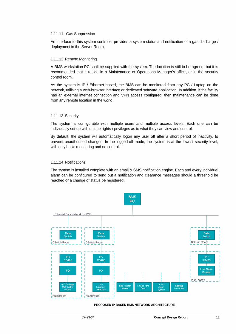
1.11 BUILDING MANAGEMENT SYSTEM (BMS)
A BMS interface system shall allow for control and monitoring of the buildings’ engineering services, HVAC systems, public lights, etc, via a digital computer interface.
The system shall have the capability to integrate with the lighting and security systems (access control and CCTV), water and fire systems if required. Level of integration requirements are to be confirmed by the operator.
Until further clarification is provided by the operator / developer, WSP shall consider the capacity provisions needed and requirements for such systems to be integrated at this conceptual design phase.
All water, gas and power meters (provided by others) shall be intelligent and have network interface connections as a standard. Gas detection shall also be interfaced in strategic areas and signal provided to the BMS should a gas leak occur.
1.11.1 HVAC
The system proposed to be installed by the Mechanical Engineer shall have an OPC (Open Protocol) communication network protocol interface card (eg. Lon, Bacnet, Modbus, Niagara, etc.) and must be able to fully be configured on the BMS for monitoring and control.
Monitoring: Live data will be available on the graphic displays for running statuses, faults, temperatures, cooling or heating modes, dirty filters, etc.
Control: Running statuses can be overridden (on or off) and time scheduled, set-points and fan speeds, etc. can be remotely adjusted.
1.11.2 Electrical and Water Supplies
The main / bulk council incoming supplies shall be monitored for the purposes of:
Reacting to peak-demand and load-shedding for the purposes of energy efficiency
Vetting of utility bills, etc.
1.11.3 Sub-Metering
Various sub-feeds across the site (offices, security, conference facilities, etc.) can be sub-metered and monitored for the purposes of auditing and potential sub-billing. This can be done on water, gas and electricity.
1.11.4 Generator
For critical systems such as diesel standby back-up generators it is crucial to be aware of the status for maintenance and repairs. Such statuses that can be monitored comprise:
Tank levels
Running status
J5423-34 Concept Design Report 11
Over-heating alarm
Over-current
Phase failure
Mains failure
Low battery
Common alarms, etc.
Graphic displays can also be developed to incorporate these items.
1.11.5 UPS
As with the generators, the UPS devices can be monitored for:
Low battery
Invertor failure
Phase failure
Over current
Bypass
On-load etc.
1.11.6 Sprinkler
The water tank level, pump statuses and zone flow sensors can be monitored.
1.11.7 Lighting
The lighting control system is purported to be a networked based system. In this case, it can be fully integrated into the BMS by communication protocols. Status monitoring can be done for the control system itself and control (switching and dimming where available) of all lighting in the facility. Time programs and schedules can be configured from either system.
If however the lighting system turns out not to be high-level protocol based control system, the interface can be achieved using I/O relay control over the contactors for basic switching control.
1.11.8 Fire Detection
Monitoring can be done of the actual fire detection system for common faults and overall fire condition, with the option to interface for the monitoring of the status of each and every detector on the graphical mimic screens.
1.11.9 Access Control
As with the Fire Detection System, the overall access control system status can be monitored.
1.11.10 CCTV
Unless it is a specifically required, this system is usually monitored at a high-level only. If it is required, the CCTV images can be incorporated into the graphical user interface (GUI) of the BMS system.
J5423-34 Concept Design Report 12
1.11.11 Gas Suppression
An interface to this system controller provides a system status and notification of a gas discharge / deployment in the Server Room.
1.11.12 Remote Monitoring
A BMS workstation PC shall be supplied with the system. The location is still to be agreed, but it is recommended that it reside in a Maintenance or Operations Manager’s office, or in the security control room.
As the system is IP / Ethernet based, the BMS can be monitored from any PC / Laptop on the network, utilising a web-browser interface or dedicated software application. In addition, if the facility has an external internet connection and VPN access configured, then maintenance can be done from any remote location in the world.
1.11.13 Security
The system is configurable with multiple users and multiple access levels. Each one can be individually set-up with unique rights / privileges as to what they can view and control.
By default, the system will automatically logon any user off after a short period of inactivity, to prevent unauthorised changes. In the logged-off mode, the system is at the lowest security level, with only basic monitoring and no control.
1.11.14 Notifications
The system is installed complete with an email & SMS notification engine. Each and every individual alarm can be configured to send out a notification and clearance messages should a threshold be reached or a change of status be registered.
PROPOSED IP BASED BMS NETWORK ARCHITECTURE
J5423-34 Concept Design Report 13
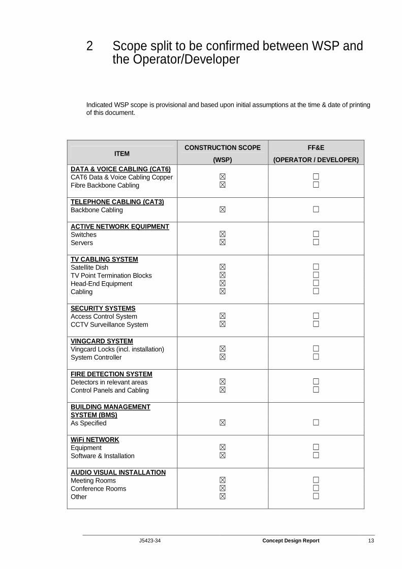
2 Scope split to be confirmed between WSP and the Operator/Developer
Indicated WSP scope is provisional and based upon initial assumptions at the time & date of printing of this document.
ITEM CONSTRUCTION SCOPE
(WSP)
FF&E
(OPERATOR / DEVELOPER) DATA & VOICE CABLING (CAT6) CAT6 Data & Voice Cabling Copper Fibre Backbone Cabling TELEPHONE CABLING (CAT3) Backbone Cabling ACTIVE NETWORK EQUIPMENT Switches Servers TV CABLING SYSTEM Satellite Dish TV Point Termination Blocks Head-End Equipment Cabling SECURITY SYSTEMS Access Control System CCTV Surveillance System VINGCARD SYSTEM Vingcard Locks (incl. installation) System Controller FIRE DETECTION SYSTEM Detectors in relevant areas Control Panels and Cabling BUILDING MANAGEMENT SYSTEM (BMS) As Specified WiFi NETWORK Equipment Software & Installation AUDIO VISUAL INSTALLATION Meeting Rooms Conference Rooms Other
J5423-34 Concept Design Report 14
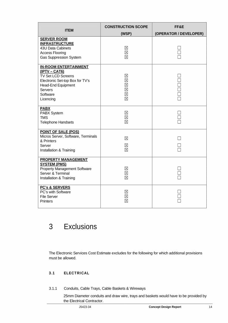
ITEM CONSTRUCTION SCOPE
(WSP)
FF&E
(OPERATOR / DEVELOPER) SERVER ROOM INFRASTRUCTURE 43U Data Cabinets Access Flooring Gas Suppression System IN-ROOM ENTERTAINMENT (IPTV – CAT6) TV Set LCD Screens Electronic Set-top Box for TV’s Head-End Equipment Servers Software Licencing PABX PABX System TMS Telephone Handsets POINT OF SALE (POS) Micros Server, Software, Terminals & Printers Server Installation & Training PROPERTY MANAGEMENT SYSTEM (PMS) Property Management Software Server & Terminal Installation & Training PC’s & SERVERS PC’s with Software File Server Printers
3 Exclusions
The Electronic Services Cost Estimate excludes for the following for which additional provisions must be allowed.
3.1 ELECTRICAL
3.1.1 Conduits, Cable Trays, Cable Baskets & Wireways
25mm Diameter conduits and draw wire, trays and baskets would have to be provided by the Electrical Contractor.
J5423-34 Concept Design Report 15
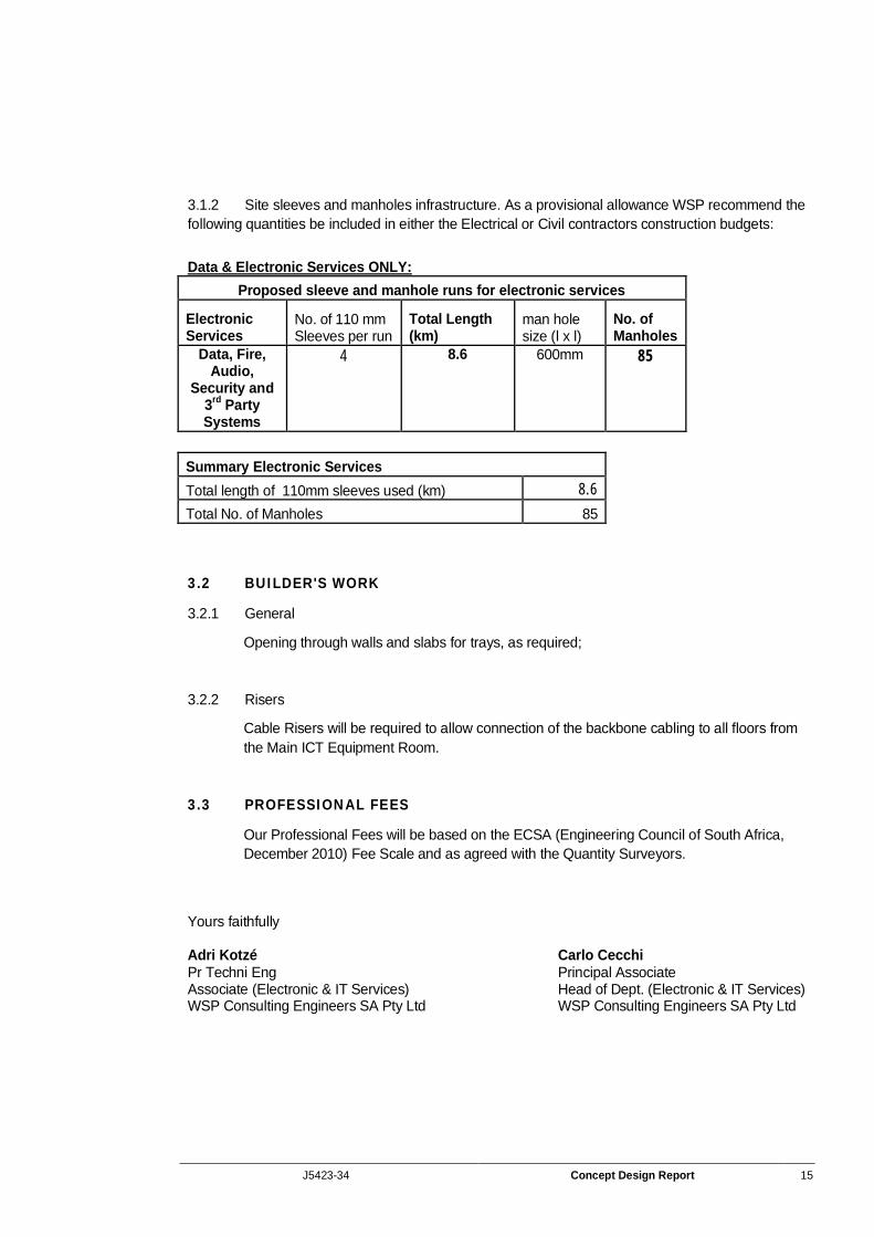
3.1.2 Site sleeves and manholes infrastructure. As a provisional allowance WSP recommend the following quantities be included in either the Electrical or Civil contractors construction budgets:
Data & Electronic Services ONLY:
Proposed sleeve and manhole runs for electronic services
Electronic Services
No. of 110 mm Sleeves per run
Total Length (km)
man hole size (l x l)
No. of Manholes
Data, Fire, Audio,
Security and 3rd Party Systems
4 8.6 600mm 85
Summary Electronic Services Total length of 110mm sleeves used (km) 8.6 Total No. of Manholes 85
3.2 BUILDER'S WORK
3.2.1 General
Opening through walls and slabs for trays, as required;
3.2.2 Risers
Cable Risers will be required to allow connection of the backbone cabling to all floors from the Main ICT Equipment Room.
3.3 PROFESSIONAL FEES
Our Professional Fees will be based on the ECSA (Engineering Council of South Africa, December 2010) Fee Scale and as agreed with the Quantity Surveyors.
Yours faithfully Adri Kotzé Carlo Cecchi Pr Techni Eng Principal Associate Associate (Electronic & IT Services) Head of Dept. (Electronic & IT Services) WSP Consulting Engineers SA Pty Ltd WSP Consulting Engineers SA Pty Ltd


![Case M.9099 - JIN JIANG / RADISSON · Radisson Blu, Radisson, Radisson Red, Park Plaza, Park Inn by Radisson. As at the end of 2017, Radisson operates 369 hotels and resorts, […]](https://img.pdfslide.net/doc/110x75/5f8e998c8519d9581635849c/case-m9099-jin-jiang-radisson-radisson-blu-radisson-radisson-red-park-plaza.jpg)