Embed Size (px)
Citation preview
CrystEngComm
Ope
n A
cces
s A
rtic
le. P
ublis
hed
on 0
5 M
arch
201
4. D
ownl
oade
d on
14/
05/2
014
17:3
2:14
. T
his
artic
le is
lice
nsed
und
er a
Cre
ativ
e C
omm
ons
Attr
ibut
ion-
Non
Com
mer
cial
3.0
Unp
orte
d L
icen
ce.
HIGHLIGHT View Article OnlineView Journal | View Issue
CrystEngComm,This journal is © The Royal Society of Chemistry 2014
Muwei Zhang
Muwei Zhang was born in thecity of Xiantao, Hubei, China in1988. After he received his B.S.degree in Chemistry from WuhanUniversity in 2009, he continuedhis Ph.D. study at Texas A&MUniversity under the guidanceof Prof. Hong-Cai “Joe” Zhou.He is currently a fifth-yearPh.D. candidate. His research isfocused on the rational designof metal–organic frameworks(MOFs) and porous polymer net-works (PPNs) for clean energy
applications. He is particularly interested in the symmetry-guided synthesis of porous materials and reticular chemistry.
Mathieu Bosch
MathHampfullbeforeof HograduwithMaygraduUniveunderZhou.in thlograp
novel advanced porous materials fstorage.
aDepartment of Chemistry, Texas A&M University, College Station, Texas, 77842,
USA. E-mail: [email protected]; Fax: +1 979 845 1595; Tel: +1 979 845 4034bDepartment of Materials Science and Engineering, Texas A&M University,
College Station, Texas, 77842, USA
† Electronic supplementary information (ESI) available: The chemicalstructures of all of the ligands, abbreviations and acronyms, and the high-resolution figures of some selected MOF structures can be found in the ESI.See DOI: 10.1039/c4ce00321g
Cite this: CrystEngComm, 2014, 16,
4069
Received 14th February 2014,Accepted 5th March 2014
DOI: 10.1039/c4ce00321g
www.rsc.org/crystengcomm
Rational design of metal–organic frameworks withanticipated porosities and functionalities†
Muwei Zhang,a Mathieu Bosch,a Thomas Gentle IIIa and Hong-Cai Zhou*ab
Metal–organic frameworks have emerged as a new category of porous materials that have intriguing
structures and diverse applications. Even though the early discovery of new MOFs appears to be
serendipitous, much effort has been made to reveal their structure–property relationships for the
purpose of rationally designing novel frameworks with expected properties. Until now, much progress
has been made to rationalize the design and synthesis of MOFs. This highlight review will outline the
recent advances on this topic from both our and other groups and provide a systematic overview of
different methods for the rational design of MOFs with desired porosities and functionalities. In this
review, we will categorize the recent efforts for rational MOF design into two different approaches: a
structural approach and a functional approach.
1. Introduction
Metal–organic frameworks (MOFs), also known as porouscoordination polymers (PCPs), are an important category ofcrystalline materials that exist as well-defined supramoleculararchitectures, in which the metal-containing units arecoordinatively connected by ditopic or polytopic organic
linkers to exhibit a variety of infinite three dimensional net-works with potential inner porosity.1–3 Due to their fascinat-ing structures and diverse applications, they have attracted agreat amount of attention in the past few decades. MOFs arepromising materials for many different applications, such asgas storage4–6 and separation,7–9 environmental conserva-tion,10–12 heterogeneous catalysis,13,14 luminescent mate-rials15,16 and biomedical materials.17,18 Since the emergenceof several representative MOF compounds such as MOF-519
and HKUST-1,20 more than 20 000 MOF structures have beenreported and studied to date.21 Due to the extraordinarilylarge extent of variability of both metal-containing units andorganic linkers, it appears that an inexhaustible amount ofMOFs could theoretically be designed and synthesized. This,on the other hand, makes it more difficult for researchers to
2014, 16, 4069–4083 | 4069
ieu Bosch was born inton, Virginia. He workedtime for several yearsattending the University
uston starting in 2010. Heated Summa Cum Laude,honors in Chemistry in2013 and has been aate student at Texas A&Mrsity since then, studying
Prof. Hong-Cai “Joe”His research interests liee synthesis and crystal-hic characterization ofor catalysis and energy
CrystEngCommHighlight
Ope
n A
cces
s A
rtic
le. P
ublis
hed
on 0
5 M
arch
201
4. D
ownl
oade
d on
14/
05/2
014
17:3
2:14
. T
his
artic
le is
lice
nsed
und
er a
Cre
ativ
e C
omm
ons
Attr
ibut
ion-
Non
Com
mer
cial
3.0
Unp
orte
d L
icen
ce.
View Article Online
search for a rational way to design a framework with proper-ties exactly suitable for a specific use. In fact, since the emer-gence of MOFs, targeted syntheses of MOFs with desiredframework cavities and customized framework functionalitieshave been a challenging problem.22–26 It is highly desirableto rationally design a novel MOF whose properties can bepredicted from its basic constructional units before theframework is synthesized.
The purpose of rationally designing MOFs is to achieveaccurate control of the framework porosity and functionalityfrom the molecular level for a customized interactionbetween the framework and its guest molecules. Though it ischallenging, chemists have been searching for solutions toovercome these difficulties. Thanks to the tunable natureand convenient functionalization processes of MOFs, chem-ists are close to achieving this goal. Reticular synthesis,27,28
introduced by Yaghi and O'Keeffe's groups, is a method inwhich, based on an existing MOF structure, the combinationof an elongated organic linkers with the same metal-containingsecondary building units (SBUs) will possibly result in an iso-reticular framework with the same topology but larger poresize. Designing ligands29,30 with various geometries and func-tional groups has enabled us to tentatively control the topologyand functionality of the resulting framework. Post-syntheticmodifications (PSMs)31,32 of MOFs, on the other hand, haveassisted us in introducing desired functional groups into theframework in a convenient way. Symmetry-guided design,25 amore recent work from our group, suggested that the scrutinyof simple mineral structures can lead to the design and syn-thesis of significantly porous frameworks with desired topol-ogy and cavity size. In consideration of the rapidly growingresearch on this topic in the past few years, herein we wouldlike to write this review to highlight the recent advances onrational MOF design from our and other research groups andprovide a general outline of different practical ways to con-struct MOFs with expected properties.
4070 | CrystEngComm, 2014, 16, 4069–4083
Thomas Gentle III
Tommy Gentle was born inMidland, Michigan in 1992. Heearned his B.S. degree in Chem-istry from the University ofSaint Thomas in Saint Paul,Minnesota in 2013 where hisfocus was on organic synthesis.In 2013, he joined Zhou's groupat Texas A&M University toobtain his Ph.D. degree inChemistry. His research inter-ests lie in ligand design formetal–organic frameworks.
It is widely accepted that MOFs are renowned for boththeir variety of captivating structures and their widespreadpotential applications.1,21 Herein, we would like to categorizerecent advances on rational MOF design into two differentapproaches: a structural approach and a functional approach.The structural approach includes the rational design of MOFswith expected structures, topologies and porosities, while thefunctional approach involves the rational design of MOFswith desired functionalities for a particular application(Scheme 1). All of these approaches will be elaborated uponin the following sections.
2. Rational design of MOFs withanticipated structures and porosities2.1 Symmetry-guided design of highly porous MOFs
Even though the composition of MOFs appears to be simple,that is, the organic linkers and metal-containing clusters(or SBUs), it is still rather difficult to accurately predict the struc-ture, porosity, and topology of the resulting framework with agiven organic linker and a metal source. First, the organicligands can adopt many different conformations, which,upon incorporation into the framework, will result in poly-morphic MOFs with completely different structures and prop-erties.33,34 Second, the metal ions can form different metalclusters, which will result in different MOF structures aswell.35,36 Third, when an elongated ligand was utilized, theresulting MOF will, in many cases, suffer from undesired andunpredictable framework interpenetration.27,37 It is still quiteproblematic to control the framework interpenetration simplyby tuning the solvothermal reaction conditions.38–40 Theselimitations made it rather challenging to design MOFs withcavities that possess the desired size, shape, and function.
The introduction of framework topology has brought novelinsights into the rational design of highly porous MOFs.25
Based on a given topology, it is easy for one to determine
This journal is © The Royal Society of Chemistry 2014
Hong-Cai Zhou
Hong-Cai “Joe” Zhou obtainedhis B.S. degree from BeijingNormal University in 1984 andhis Ph.D. degree in 2000 fromTexas A&M University underthe supervision of F. A. Cotton.After a postdoctoral stint atHarvard University with R. H.Holm, he joined the faculty ofMiami University, Oxford, in2002. He rose to the rank of fullprofessor within six years andmoved to Texas A&M Universityin 2008. He was a guest editor
(co-editors: Jeffrey Long and Omar Yaghi) for the first ChemicalReviews thematic issue on Metal–Organic Frameworks in 2012.He has been an associate editor for the ACS journal InorganicChemistry since June 2013.
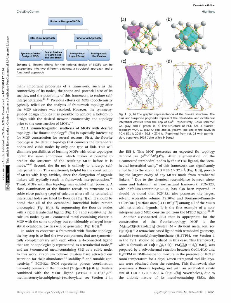
Fig. 1 (a, b) The graphic representation of the fluorite structure. Thepink and turquoise polyhedra represent the tetrahedral and octahedralinterstitial cavities from the ccp of Ca2+, respectively. Color scheme:Ca, gray; and F, green. (c, d) The structure of PCN-521, a fluorite-topology MOF. C, gray; O, red; and Zr, yellow. The size of the cavity inPCN-521 is 20.5 × 20.5 × 37.4 Å. (Reprinted from ref. 25 with permis-sion, copyright 2014 John Wiley & Sons.)
Scheme 1 Recent efforts for the rational design of MOFs can becategorized into two different catalogs: a structural approach and afunctional approach.
CrystEngComm Highlight
Ope
n A
cces
s A
rtic
le. P
ublis
hed
on 0
5 M
arch
201
4. D
ownl
oade
d on
14/
05/2
014
17:3
2:14
. T
his
artic
le is
lice
nsed
und
er a
Cre
ativ
e C
omm
ons
Attr
ibut
ion-
Non
Com
mer
cial
3.0
Unp
orte
d L
icen
ce.
View Article Online
many important properties of a framework, such as theconnectivity of its nodes, the shape and potential size of itscavities, and the possibility of this framework to endure self-interpenetration.41–44 Previous efforts on MOF topochemistrytypically relied on the analysis of framework topology afterthe MOF structure was resolved. However, the symmetry-guided design implies it is possible to achieve a bottom-updesign with the desired network connectivity and topologyprior to the construction of MOFs.25
2.1.1 Symmetry-guided synthesis of MOFs with desiredtopology. The fluorite topology45 (flu) is especially interestingfor MOF construction for several reasons. First, the fluoritetopology is the default topology that connects the tetrahedralnodes and cubic nodes by only one type of link. This willeliminate possibilities of forming MOFs with other topologiesunder the same conditions, which makes it possible topredict the structure of the resulting MOF before it ismade.46,47 Second, the flu net is unlikely to undergo self-interpenetration. This is extremely helpful for the constructionof MOFs with large cavities, since the elongation of organiclinkers will typically result in framework interpenetration.48
Third, MOFs with this topology may exhibit high porosity. Aclose examination of the fluorite reveals its structure as acubic close packing (ccp) of calcium where all its tetrahedralinterstitial holes are filled by fluoride (Fig. 1(a)). It should benoted that all of the octahedral interstitial holes remainunoccupied (Fig. 1(b)). By augmenting the fluoride nodeswith a rigid tetrahedral ligand (Fig. 1(c)) and substituting thecalcium nodes by an 8-connected metal-containing cluster, aMOF with the same topology but considerably enlarged inter-stitial octahedral cavities will be generated (Fig. 1(d)).25
In order to construct a framework with fluorite topology,the key step is to find the two components that are symmetri-cally complementary with each other: a 4-connected ligandthat can be topologically represented as a tetrahedral node,49
and an 8-connected metal-containing SBU as a cubic node.In this work, zirconium polyoxo clusters have attracted ourattention for their abundance,50 stability,51 and tunable con-nectivity.36 PCN-521 (PCN represents porous coordinationnetwork) consists of 8-connected [Zr6(μ3-OH)8(OH)8] clusterscombined with the MTBC ligand (MTBC = 4′,4″,4‴,4″″-methanetetrayltetrabiphenyl-4-carboxylate, see Section 1 in
This journal is © The Royal Society of Chemistry 2014
the ESI†). This MOF possesses an expected flu topologydenoted as (412·612·84)(46)2. After augmentation of the4-connected tetrahedral nodes by the MTBC ligand, the “octa-hedral interstitial cavity” of this framework was significantlyamplified to the size of 20.5 × 20.5 × 37.4 Å (Fig. 1(d)), provid-ing the largest cavity of any MOFs made from tetrahedrallinkers.25 Due to the chemical resemblance between zirco-nium and hafnium, an isostructural framework, PCN-523,with hafnium-containing SBUs, has also been reported. Itshould be noted that PCN-521 also possesses the largestsolvent accessible volume (78.50%) and Brunauer–Emmett–Teller (BET) surface area (3411 m2 g−1) among all of the MOFswith tetrahedral ligands. It is the first example of a non-interpenetrated MOF constructed from the MTBC ligand.52–54
Another 8-connected SBU that is appropriate for theconstruction of the fluorite-topology MOF is the[M4(μ4-Cl)(tetrazolate)8] cluster (M = divalent metal ion, seeFig. 2(a)).55 A tetrazolate-based ligand with tetrahedral geometry,tetrakis(4-tetrazolylphenyl)methane (H4TTPM, see Section 1in the ESI†) should be utilized in this case. This framework,with a formula of Cu[Cu4(μ4-Cl)(TTPM)2]2(CuCl2)(DMF)5 wasprepared by a solvothermal reaction between CuCl2·H2O andH4TTPM in DMF–methanol mixture in the presence of HCl atroom temperature for 4 days. Green tetragonal rod-like crys-tals were obtained from the reaction. This framework alsopossesses a fluorite topology net with an octahedral cavitysize of 17.8 × 17.8 × 27.5 Å. (Fig. 2(b)) Nevertheless, due tothe anionic nature of its metal-containing SBUs, this
CrystEngComm, 2014, 16, 4069–4083 | 4071
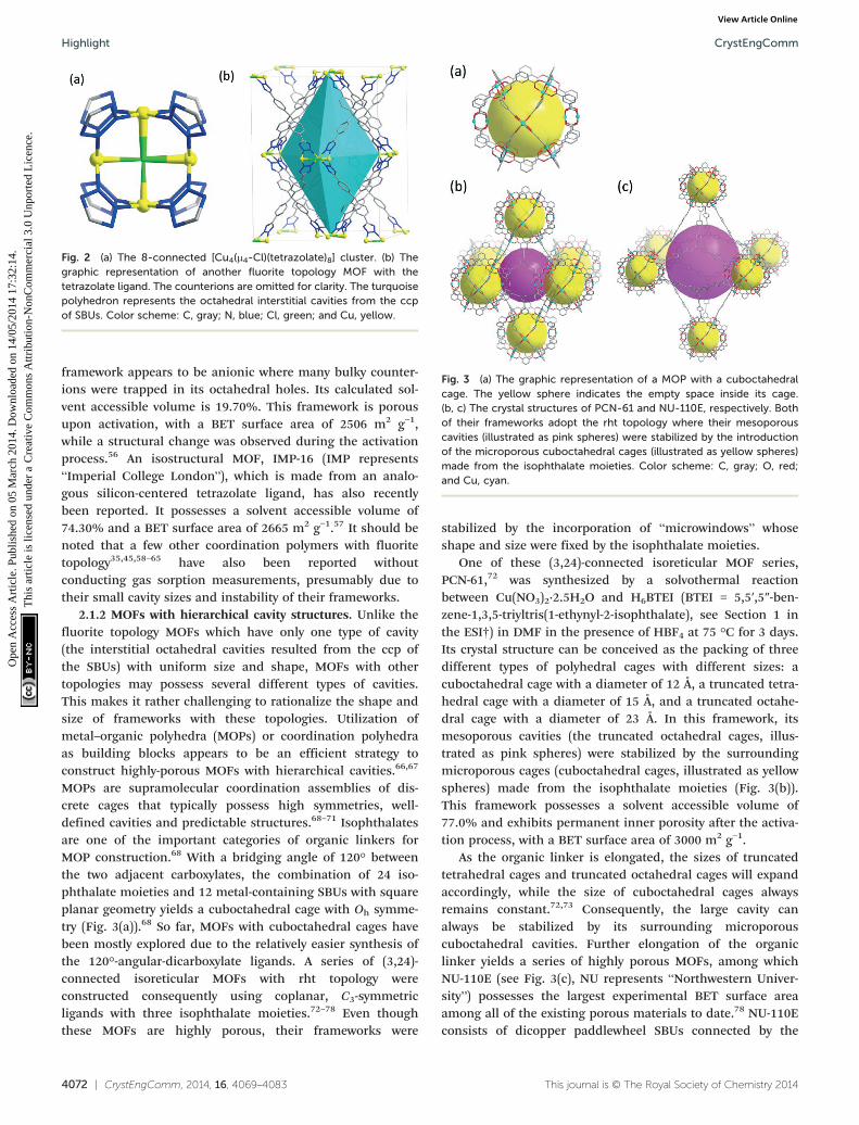
Fig. 2 (a) The 8-connected [Cu4(μ4-Cl)(tetrazolate)8] cluster. (b) Thegraphic representation of another fluorite topology MOF with thetetrazolate ligand. The counterions are omitted for clarity. The turquoisepolyhedron represents the octahedral interstitial cavities from the ccpof SBUs. Color scheme: C, gray; N, blue; Cl, green; and Cu, yellow.
Fig. 3 (a) The graphic representation of a MOP with a cuboctahedralcage. The yellow sphere indicates the empty space inside its cage.(b, c) The crystal structures of PCN-61 and NU-110E, respectively. Bothof their frameworks adopt the rht topology where their mesoporouscavities (illustrated as pink spheres) were stabilized by the introductionof the microporous cuboctahedral cages (illustrated as yellow spheres)made from the isophthalate moieties. Color scheme: C, gray; O, red;and Cu, cyan.
CrystEngCommHighlight
Ope
n A
cces
s A
rtic
le. P
ublis
hed
on 0
5 M
arch
201
4. D
ownl
oade
d on
14/
05/2
014
17:3
2:14
. T
his
artic
le is
lice
nsed
und
er a
Cre
ativ
e C
omm
ons
Attr
ibut
ion-
Non
Com
mer
cial
3.0
Unp
orte
d L
icen
ce.
View Article Online
framework appears to be anionic where many bulky counter-ions were trapped in its octahedral holes. Its calculated sol-vent accessible volume is 19.70%. This framework is porousupon activation, with a BET surface area of 2506 m2 g−1,while a structural change was observed during the activationprocess.56 An isostructural MOF, IMP-16 (IMP represents“Imperial College London”), which is made from an analo-gous silicon-centered tetrazolate ligand, has also recentlybeen reported. It possesses a solvent accessible volume of74.30% and a BET surface area of 2665 m2 g−1.57 It should benoted that a few other coordination polymers with fluoritetopology35,45,58–65 have also been reported withoutconducting gas sorption measurements, presumably due totheir small cavity sizes and instability of their frameworks.
2.1.2 MOFs with hierarchical cavity structures. Unlike thefluorite topology MOFs which have only one type of cavity(the interstitial octahedral cavities resulted from the ccp ofthe SBUs) with uniform size and shape, MOFs with othertopologies may possess several different types of cavities.This makes it rather challenging to rationalize the shape andsize of frameworks with these topologies. Utilization ofmetal–organic polyhedra (MOPs) or coordination polyhedraas building blocks appears to be an efficient strategy toconstruct highly-porous MOFs with hierarchical cavities.66,67
MOPs are supramolecular coordination assemblies of dis-crete cages that typically possess high symmetries, well-defined cavities and predictable structures.68–71 Isophthalatesare one of the important categories of organic linkers forMOP construction.68 With a bridging angle of 120° betweenthe two adjacent carboxylates, the combination of 24 iso-phthalate moieties and 12 metal-containing SBUs with squareplanar geometry yields a cuboctahedral cage with Oh symme-try (Fig. 3(a)).68 So far, MOFs with cuboctahedral cages havebeen mostly explored due to the relatively easier synthesis ofthe 120°-angular-dicarboxylate ligands. A series of (3,24)-connected isoreticular MOFs with rht topology wereconstructed consequently using coplanar, C3-symmetricligands with three isophthalate moieties.72–78 Even thoughthese MOFs are highly porous, their frameworks were
4072 | CrystEngComm, 2014, 16, 4069–4083
stabilized by the incorporation of “microwindows” whoseshape and size were fixed by the isophthalate moieties.
One of these (3,24)-connected isoreticular MOF series,PCN-61,72 was synthesized by a solvothermal reactionbetween Cu(NO3)2·2.5H2O and H6BTEI (BTEI = 5,5′,5″-ben-zene-1,3,5-triyltris(1-ethynyl-2-isophthalate), see Section 1 inthe ESI†) in DMF in the presence of HBF4 at 75 °C for 3 days.Its crystal structure can be conceived as the packing of threedifferent types of polyhedral cages with different sizes: acuboctahedral cage with a diameter of 12 Å, a truncated tetra-hedral cage with a diameter of 15 Å, and a truncated octahe-dral cage with a diameter of 23 Å. In this framework, itsmesoporous cavities (the truncated octahedral cages, illus-trated as pink spheres) were stabilized by the surroundingmicroporous cages (cuboctahedral cages, illustrated as yellowspheres) made from the isophthalate moieties (Fig. 3(b)).This framework possesses a solvent accessible volume of77.0% and exhibits permanent inner porosity after the activa-tion process, with a BET surface area of 3000 m2 g−1.
As the organic linker is elongated, the sizes of truncatedtetrahedral cages and truncated octahedral cages will expandaccordingly, while the size of cuboctahedral cages alwaysremains constant.72,73 Consequently, the large cavity canalways be stabilized by its surrounding microporouscuboctahedral cavities. Further elongation of the organiclinker yields a series of highly porous MOFs, among whichNU-110E (see Fig. 3(c), NU represents “Northwestern Univer-sity”) possesses the largest experimental BET surface areaamong all of the existing porous materials to date.78 NU-110Econsists of dicopper paddlewheel SBUs connected by the
This journal is © The Royal Society of Chemistry 2014
CrystEngComm Highlight
Ope
n A
cces
s A
rtic
le. P
ublis
hed
on 0
5 M
arch
201
4. D
ownl
oade
d on
14/
05/2
014
17:3
2:14
. T
his
artic
le is
lice
nsed
und
er a
Cre
ativ
e C
omm
ons
Attr
ibut
ion-
Non
Com
mer
cial
3.0
Unp
orte
d L
icen
ce.
View Article Online
BTTEI ligand (BTTEI = 5,5′,5″-(((benzene-1,3,5-triyl-tris(ethyne-2,1-diyl))tris(benzene-4,1-diyl)tris(ethyne-2,1-diyl))triisophthalate,see Section 1 in the ESI†). This framework is isoreticular tothe PCN-61 series. Due to its highly porous nature, supercriti-cal CO2 activation has to be applied to maintain the integrityof its framework. It has a solvent accessible volume of 93.0%and exhibits a BET surface area of 7140 m2 g−1.
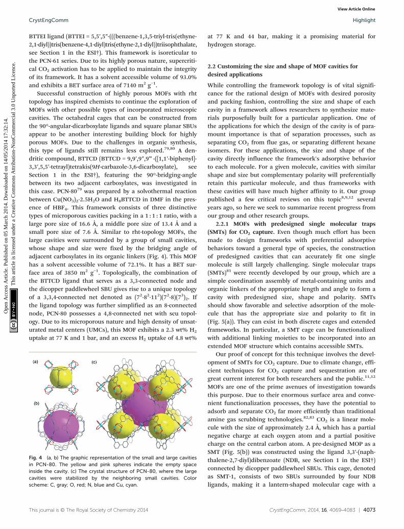
Successful construction of highly porous MOFs with rhttopology has inspired chemists to continue the exploration ofMOFs with other possible types of incorporated microscopiccavities. The octahedral cages that can be constructed fromthe 90°-angular-dicarboxylate ligands and square planar SBUsappear to be another interesting building block for highlyporous MOFs. Due to the challenges in organic synthesis,this type of ligands still remains less explored.79,80 A den-dritic compound, BTTCD (BTTCD = 9,9′,9″,9‴-([1,1′-biphenyl]-3,3′,5,5′-tetrayl)tetrakis(9H-carbazole-3,6-dicarboxylate), seeSection 1 in the ESI†), featuring the 90°-bridging-anglebetween its two adjacent carboxylates, was investigated inthis case. PCN-8079 was prepared by a solvothermal reactionbetween Cu(NO3)2·2.5H2O and H8BTTCD in DMF in the pres-ence of HBF4. This framework consists of three distinctivetypes of microporous cavities packing in a 1 : 1 : 1 ratio, with alarge pore size of 16.6 Å, a middle pore size of 13.4 Å and asmall pore size of 7.6 Å. Similar to rht-topology MOFs, thelarge cavities were surrounded by a group of small cavities,whose shape and size were fixed by the bridging angle ofadjacent carboxylates in its organic linkers (Fig. 4). This MOFhas a solvent accessible volume of 72.1%. It has a BET sur-face area of 3850 m2 g−1. Topologically, the combination ofthe BTTCD ligand that serves as a 3,3-connected node andthe dicopper paddlewheel SBU gives rise to a unique topologyof a 3,3,4-connected net denoted as (72·82·112)(72·8)(73)2. Ifthe ligand topology was further simplified as an 8-connectednode, PCN-80 possesses a 4,8-connected net with scu topol-ogy. Due to its microporous nature and high density of unsat-urated metal centers (UMCs), this MOF exhibits a 2.3 wt% H2
uptake at 77 K and 1 bar, and an excess H2 uptake of 4.8 wt%
This journal is © The Royal Society of Chemistry 2014
Fig. 4 (a, b) The graphic representation of the small and large cavitiesin PCN-80. The yellow and pink spheres indicate the empty spaceinside the cavity. (c) The crystal structure of PCN-80, where the largecavities were stabilized by the neighboring small cavities. Colorscheme: C, gray; O, red; N, blue and Cu, cyan.
at 77 K and 44 bar, making it a promising material forhydrogen storage.
2.2 Customizing the size and shape of MOF cavities fordesired applications
While controlling the framework topology is of vital signifi-cance for the rational design of MOFs with desired porosityand packing fashion, controlling the size and shape of eachcavity in a framework allows researchers to synthesize mate-rials purposefully built for a particular application. One ofthe applications for which the design of the cavity is of para-mount importance is that of separation processes, such asseparating CO2 from flue gas, or separating different hexaneisomers. For these applications, the size and shape of thecavity directly influence the framework's adsorptive behaviorto each molecule. For a given molecule, cavities with similarshape and size but complementary polarity will preferentiallyretain this particular molecule, and thus frameworks withthese cavities will have much higher affinity to it. Our grouppublished a few critical reviews on this topic8,9,12 severalyears ago, so here we seek to summarize recent progress fromour group and other research groups.
2.2.1 MOFs with predesigned single molecular traps(SMTs) for CO2 capture. Even though much effort has beenmade to design frameworks with preferential adsorptivebehaviors toward a general type of species, the constructionof predesigned cavities that can accurately fit one singlemolecule is still largely challenging. Single molecular traps(SMTs)81 were recently developed by our group, which are asimple coordination assembly of metal-containing units andorganic linkers of the appropriate length and angle to form acavity with predesigned size, shape and polarity. SMTsshould show favorable and selective adsorption of the mole-cule that has the appropriate size and polarity to fit in(Fig. 5(a)). They can exist in both discrete cages and extendedframeworks. In particular, a SMT cage can be functionalizedwith additional linking moieties to be incorporated into anextended MOF structure which contains accessible SMTs.
Our proof of concept for this technique involves the devel-opment of SMTs for CO2 capture. Due to climate change, effi-cient techniques for CO2 capture and sequestration are ofgreat current interest for both researchers and the public.11,12
MOFs are one of the prime avenues of investigation towardsthis purpose. Due to their enormous surface area and conve-nient functionalization processes, they have the potential toadsorb and separate CO2 far more efficiently than traditionalamine gas scrubbing technologies.82,83 CO2 is a linear mole-cule with the size of approximately 2.4 Å, which has a partialnegative charge at each oxygen atom and a partial positivecharge on the central carbon atom. A pre-designed MOP as aSMT (Fig. 5(b)) was constructed using the ligand 3,3′-(naph-thalene-2,7-diyl)dibenzoate (NDB, see Section 1 in the ESI†)connected by dicopper paddlewheel SBUs. This cage, denotedas SMT-1, consists of two SBUs surrounded by four NDBligands, making it a lantern-shaped molecular cage with a
CrystEngComm, 2014, 16, 4069–4083 | 4073
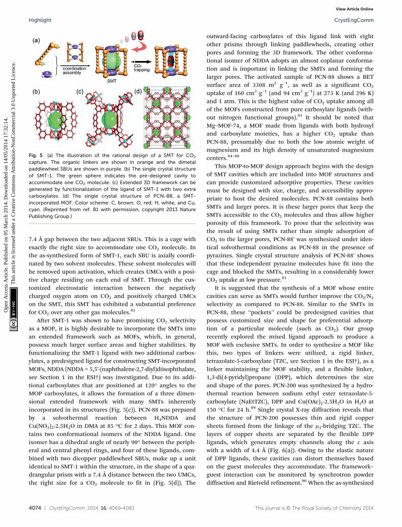
Fig. 5 (a) The illustration of the rational design of a SMT for CO2
capture. The organic linkers are shown in orange and the dimetalpaddlewheel SBUs are shown in purple. (b) The single crystal structureof SMT-1. The green sphere indicates the pre-designed cavity toaccommodate one CO2 molecule. (c) Extended 3D framework can begenerated by functionalization of the ligand of SMT-1 with two extracarboxylates. (d) The single crystal structure of PCN-88, a SMT-incorporated MOF. Color scheme: C, brown; O, red; H, white, and Cu,cyan. (Reprinted from ref. 81 with permission, copyright 2013 NaturePublishing Group.)
CrystEngCommHighlight
Ope
n A
cces
s A
rtic
le. P
ublis
hed
on 0
5 M
arch
201
4. D
ownl
oade
d on
14/
05/2
014
17:3
2:14
. T
his
artic
le is
lice
nsed
und
er a
Cre
ativ
e C
omm
ons
Attr
ibut
ion-
Non
Com
mer
cial
3.0
Unp
orte
d L
icen
ce.
View Article Online
7.4 Å gap between the two adjacent SBUs. This is a cage withexactly the right size to accommodate one CO2 molecule. Inthe as-synthesized form of SMT-1, each SBU is axially coordi-nated by two solvent molecules. These solvent molecules willbe removed upon activation, which creates UMCs with a posi-tive charge residing on each end of SMT. Through the cus-tomized electrostatic interaction between the negativelycharged oxygen atom on CO2 and positively charged UMCson the SMT, this SMT has exhibited a substantial preferencefor CO2 over any other gas molecules.81
After SMT-1 was shown to have promising CO2 selectivityas a MOP, it is highly desirable to incorporate the SMTs intoan extended framework such as MOFs, which, in general,possess much larger surface areas and higher stabilities. Byfunctionalizing the SMT-1 ligand with two additional carbox-ylates, a predesigned ligand for constructing SMT-incorporatedMOFs, NDDA (NDDA = 5,5′-(naphthalene-2,7-diyl)diisophthalate,see Section 1 in the ESI†) was investigated. Due to its addi-tional carboxylates that are positioned at 120° angles to theMOP carboxylates, it allows the formation of a three dimen-sional extended framework with many SMTs inherentlyincorporated in its structures (Fig. 5(c)). PCN-88 was preparedby a solvothermal reaction between H4NDDA andCu(NO3)2·2.5H2O in DMA at 85 °C for 2 days. This MOF con-tains two conformational isomers of the NDDA ligand. Oneisomer has a dihedral angle of nearly 90° between the periph-eral and central phenyl rings, and four of these ligands, com-bined with two dicopper paddlewheel SBUs, make up a unitidentical to SMT-1 within the structure, in the shape of a qua-drangular prism with a 7.4 Å distance between the two UMCs,the right size for a CO2 molecule to fit in (Fig. 5(d)). The
4074 | CrystEngComm, 2014, 16, 4069–4083
outward-facing carboxylates of this ligand link with eightother prisms through linking paddlewheels, creating otherpores and forming the 3D framework. The other conforma-tional isomer of NDDA adopts an almost coplanar conforma-tion and is important in linking the SMTs and forming thelarger pores. The activated sample of PCN-88 shows a BETsurface area of 3308 m2 g−1, as well as a significant CO2
uptake of 160 cm3 g−1 (and 94 cm3 g−1) at 273 K (and 296 K)and 1 atm. This is the highest value of CO2 uptake among allof the MOFs constructed from pure carboxylate ligands (with-out nitrogen functional groups).81 It should be noted thatMg–MOF-74, a MOF made from ligands with both hydroxyland carboxylate moieties, has a higher CO2 uptake thanPCN-88, presumably due to both the low atomic weight ofmagnesium and its high density of unsaturated magnesiumcenters.84–88
This MOP-to-MOF design approach begins with the designof SMT cavities which are included into MOF structures andcan provide customized adsorptive properties. These cavitiesmust be designed with size, charge, and accessibility appro-priate to host the desired molecules. PCN-88 contains bothSMTs and larger pores. It is these larger pores that keep theSMTs accessible to the CO2 molecules and thus allow higherporosity of this framework. To prove that the selectivity wasthe result of using SMTs rather than simple adsorption ofCO2 to the larger pores, PCN-88′ was synthesized under iden-tical solvothermal conditions as PCN-88 in the presence ofpyrazines. Single crystal structure analysis of PCN-88′ showsthat these independent pyrazine molecules have fit into thecage and blocked the SMTs, resulting in a considerably lowerCO2 uptake at low pressure.81
It is suggested that the synthesis of a MOF whose entirecavities can serve as SMTs would further improve the CO2/N2
selectivity as compared to PCN-88. Similar to the SMTs inPCN-88, these “pockets” could be predesigned cavities thatpossess customized size and shape for preferential adsorp-tion of a particular molecule (such as CO2). Our grouprecently explored the mixed ligand approach to produce aMOF with exclusive SMTs. In order to synthesize a MOF likethis, two types of linkers were utilized, a rigid linker,tetrazolate-5-carboxylate (TZC, see Section 1 in the ESI†), as alinker maintaining the MOF stability, and a flexible linker,1,3-di(4-pyridyl)propane (DPP), which determines the sizeand shape of the pores. PCN-200 was synthesized by a hydro-thermal reaction between sodium ethyl ester tetrazolate-5-carboxylate (NaEtTZC), DPP and Cu(OAc)2·2.5H2O in H2O at150 °C for 24 h.89 Single crystal X-ray diffraction reveals thatthe structure of PCN-200 possesses thin and rigid coppersheets formed from the linkage of the μ3-bridging TZC. Thelayers of copper sheets are separated by the flexible DPPligands, which generates empty channels along the c axiswith a width of 4.4 Å (Fig. 6(a)). Owing to the elastic natureof DPP ligands, these cavities can distort themselves basedon the guest molecules they accommodate. The framework–guest interaction can be monitored by synchrotron powderdiffraction and Rietveld refinement.90 When the as-synthesized
This journal is © The Royal Society of Chemistry 2014
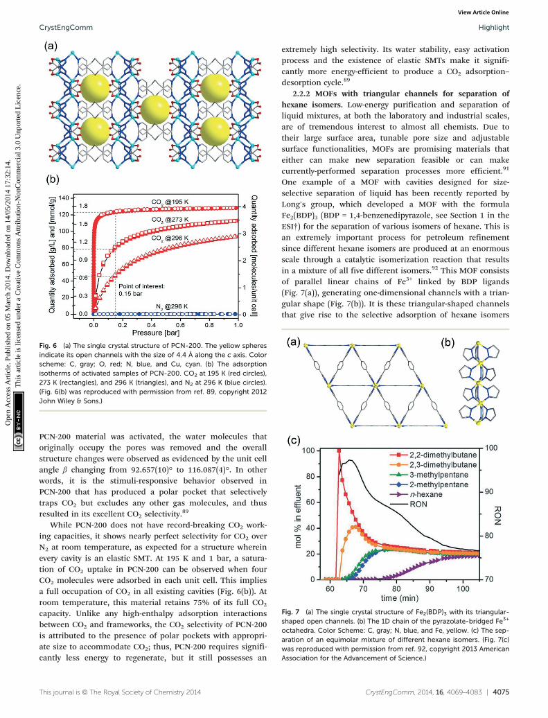
Fig. 6 (a) The single crystal structure of PCN-200. The yellow spheresindicate its open channels with the size of 4.4 Å along the c axis. Colorscheme: C, gray; O, red; N, blue, and Cu, cyan. (b) The adsorptionisotherms of activated samples of PCN-200. CO2 at 195 K (red circles),273 K (rectangles), and 296 K (triangles), and N2 at 296 K (blue circles).(Fig. 6(b) was reproduced with permission from ref. 89, copyright 2012John Wiley & Sons.)
Fig. 7 (a) The single crystal structure of Fe2(BDP)3 with its triangular-shaped open channels. (b) The 1D chain of the pyrazolate-bridged Fe3+
octahedra. Color Scheme: C, gray; N, blue, and Fe, yellow. (c) The sep-aration of an equimolar mixture of different hexane isomers. (Fig. 7(c)was reproduced with permission from ref. 92, copyright 2013 AmericanAssociation for the Advancement of Science.)
CrystEngComm Highlight
Ope
n A
cces
s A
rtic
le. P
ublis
hed
on 0
5 M
arch
201
4. D
ownl
oade
d on
14/
05/2
014
17:3
2:14
. T
his
artic
le is
lice
nsed
und
er a
Cre
ativ
e C
omm
ons
Attr
ibut
ion-
Non
Com
mer
cial
3.0
Unp
orte
d L
icen
ce.
View Article Online
PCN-200 material was activated, the water molecules thatoriginally occupy the pores was removed and the overallstructure changes were observed as evidenced by the unit cellangle β changing from 92.657(10)° to 116.087(4)°. In otherwords, it is the stimuli-responsive behavior observed inPCN-200 that has produced a polar pocket that selectivelytraps CO2 but excludes any other gas molecules, and thusresulted in its excellent CO2 selectivity.
89
While PCN-200 does not have record-breaking CO2 work-ing capacities, it shows nearly perfect selectivity for CO2 overN2 at room temperature, as expected for a structure whereinevery cavity is an elastic SMT. At 195 K and 1 bar, a satura-tion of CO2 uptake in PCN-200 can be observed when fourCO2 molecules were adsorbed in each unit cell. This impliesa full occupation of CO2 in all existing cavities (Fig. 6(b)). Atroom temperature, this material retains 75% of its full CO2
capacity. Unlike any high-enthalpy adsorption interactionsbetween CO2 and frameworks, the CO2 selectivity of PCN-200is attributed to the presence of polar pockets with appropri-ate size to accommodate CO2; thus, PCN-200 requires signifi-cantly less energy to regenerate, but it still possesses an
This journal is © The Royal Society of Chemistry 2014
extremely high selectivity. Its water stability, easy activationprocess and the existence of elastic SMTs make it signifi-cantly more energy-efficient to produce a CO2 adsorption–desorption cycle.89
2.2.2 MOFs with triangular channels for separation ofhexane isomers. Low-energy purification and separation ofliquid mixtures, at both the laboratory and industrial scales,are of tremendous interest to almost all chemists. Due totheir large surface area, tunable pore size and adjustablesurface functionalities, MOFs are promising materials thateither can make new separation feasible or can makecurrently-performed separation processes more efficient.91
One example of a MOF with cavities designed for size-selective separation of liquid has been recently reported byLong's group, which developed a MOF with the formulaFe2(BDP)3 (BDP = 1,4-benzenedipyrazole, see Section 1 in theESI†) for the separation of various isomers of hexane. This isan extremely important process for petroleum refinementsince different hexane isomers are produced at an enormousscale through a catalytic isomerization reaction that resultsin a mixture of all five different isomers.92 This MOF consistsof parallel linear chains of Fe3+ linked by BDP ligands(Fig. 7(a)), generating one-dimensional channels with a trian-gular shape (Fig. 7(b)). It is these triangular-shaped channelsthat give rise to the selective adsorption of hexane isomers
CrystEngComm, 2014, 16, 4069–4083 | 4075
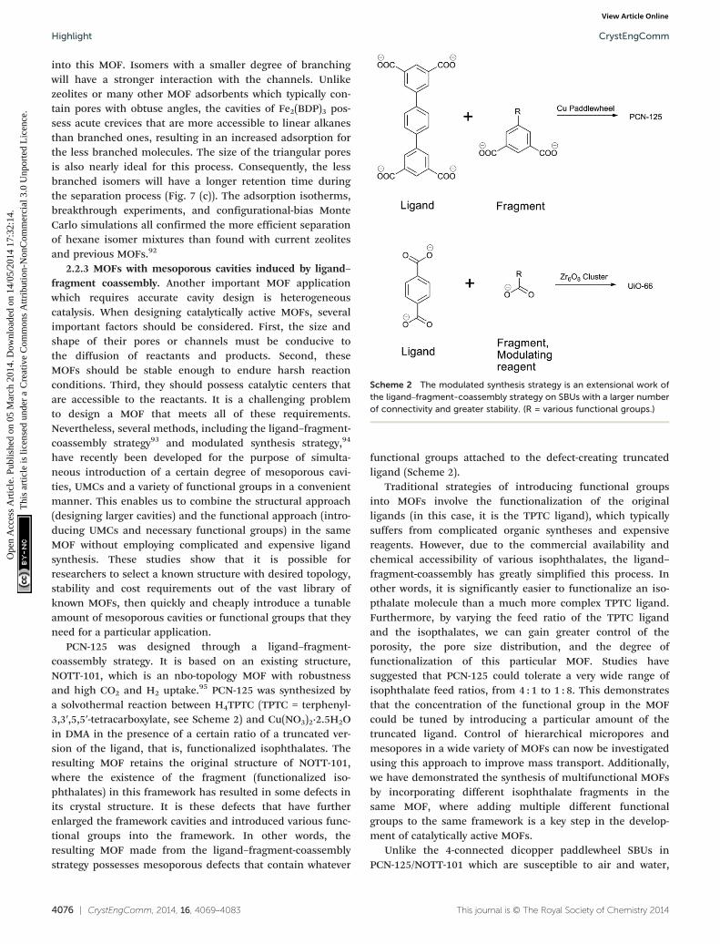
Scheme 2 The modulated synthesis strategy is an extensional work ofthe ligand–fragment-coassembly strategy on SBUs with a larger numberof connectivity and greater stability. (R = various functional groups.)
CrystEngCommHighlight
Ope
n A
cces
s A
rtic
le. P
ublis
hed
on 0
5 M
arch
201
4. D
ownl
oade
d on
14/
05/2
014
17:3
2:14
. T
his
artic
le is
lice
nsed
und
er a
Cre
ativ
e C
omm
ons
Attr
ibut
ion-
Non
Com
mer
cial
3.0
Unp
orte
d L
icen
ce.
View Article Online
into this MOF. Isomers with a smaller degree of branchingwill have a stronger interaction with the channels. Unlikezeolites or many other MOF adsorbents which typically con-tain pores with obtuse angles, the cavities of Fe2(BDP)3 pos-sess acute crevices that are more accessible to linear alkanesthan branched ones, resulting in an increased adsorption forthe less branched molecules. The size of the triangular poresis also nearly ideal for this process. Consequently, the lessbranched isomers will have a longer retention time duringthe separation process (Fig. 7 (c)). The adsorption isotherms,breakthrough experiments, and configurational-bias MonteCarlo simulations all confirmed the more efficient separationof hexane isomer mixtures than found with current zeolitesand previous MOFs.92
2.2.3 MOFs with mesoporous cavities induced by ligand–fragment coassembly. Another important MOF applicationwhich requires accurate cavity design is heterogeneouscatalysis. When designing catalytically active MOFs, severalimportant factors should be considered. First, the size andshape of their pores or channels must be conducive tothe diffusion of reactants and products. Second, theseMOFs should be stable enough to endure harsh reactionconditions. Third, they should possess catalytic centers thatare accessible to the reactants. It is a challenging problemto design a MOF that meets all of these requirements.Nevertheless, several methods, including the ligand–fragment-coassembly strategy93 and modulated synthesis strategy,94
have recently been developed for the purpose of simulta-neous introduction of a certain degree of mesoporous cavi-ties, UMCs and a variety of functional groups in a convenientmanner. This enables us to combine the structural approach(designing larger cavities) and the functional approach (intro-ducing UMCs and necessary functional groups) in the sameMOF without employing complicated and expensive ligandsynthesis. These studies show that it is possible forresearchers to select a known structure with desired topology,stability and cost requirements out of the vast library ofknown MOFs, then quickly and cheaply introduce a tunableamount of mesoporous cavities or functional groups that theyneed for a particular application.
PCN-125 was designed through a ligand–fragment-coassembly strategy. It is based on an existing structure,NOTT-101, which is an nbo-topology MOF with robustnessand high CO2 and H2 uptake.95 PCN-125 was synthesized bya solvothermal reaction between H4TPTC (TPTC = terphenyl-3,3′,5,5′-tetracarboxylate, see Scheme 2) and Cu(NO3)2·2.5H2Oin DMA in the presence of a certain ratio of a truncated ver-sion of the ligand, that is, functionalized isophthalates. Theresulting MOF retains the original structure of NOTT-101,where the existence of the fragment (functionalized iso-phthalates) in this framework has resulted in some defects inits crystal structure. It is these defects that have furtherenlarged the framework cavities and introduced various func-tional groups into the framework. In other words, theresulting MOF made from the ligand–fragment-coassemblystrategy possesses mesoporous defects that contain whatever
4076 | CrystEngComm, 2014, 16, 4069–4083
functional groups attached to the defect-creating truncatedligand (Scheme 2).
Traditional strategies of introducing functional groupsinto MOFs involve the functionalization of the originalligands (in this case, it is the TPTC ligand), which typicallysuffers from complicated organic syntheses and expensivereagents. However, due to the commercial availability andchemical accessibility of various isophthalates, the ligand–fragment-coassembly has greatly simplified this process. Inother words, it is significantly easier to functionalize an iso-pthalate molecule than a much more complex TPTC ligand.Furthermore, by varying the feed ratio of the TPTC ligandand the isopthalates, we can gain greater control of theporosity, the pore size distribution, and the degree offunctionalization of this particular MOF. Studies havesuggested that PCN-125 could tolerate a very wide range ofisophthalate feed ratios, from 4 : 1 to 1 : 8. This demonstratesthat the concentration of the functional group in the MOFcould be tuned by introducing a particular amount of thetruncated ligand. Control of hierarchical micropores andmesopores in a wide variety of MOFs can now be investigatedusing this approach to improve mass transport. Additionally,we have demonstrated the synthesis of multifunctional MOFsby incorporating different isophthalate fragments in thesame MOF, where adding multiple different functionalgroups to the same framework is a key step in the develop-ment of catalytically active MOFs.
Unlike the 4-connected dicopper paddlewheel SBUs inPCN-125/NOTT-101 which are susceptible to air and water,
This journal is © The Royal Society of Chemistry 2014
CrystEngComm Highlight
Ope
n A
cces
s A
rtic
le. P
ublis
hed
on 0
5 M
arch
201
4. D
ownl
oade
d on
14/
05/2
014
17:3
2:14
. T
his
artic
le is
lice
nsed
und
er a
Cre
ativ
e C
omm
ons
Attr
ibut
ion-
Non
Com
mer
cial
3.0
Unp
orte
d L
icen
ce.
View Article Online
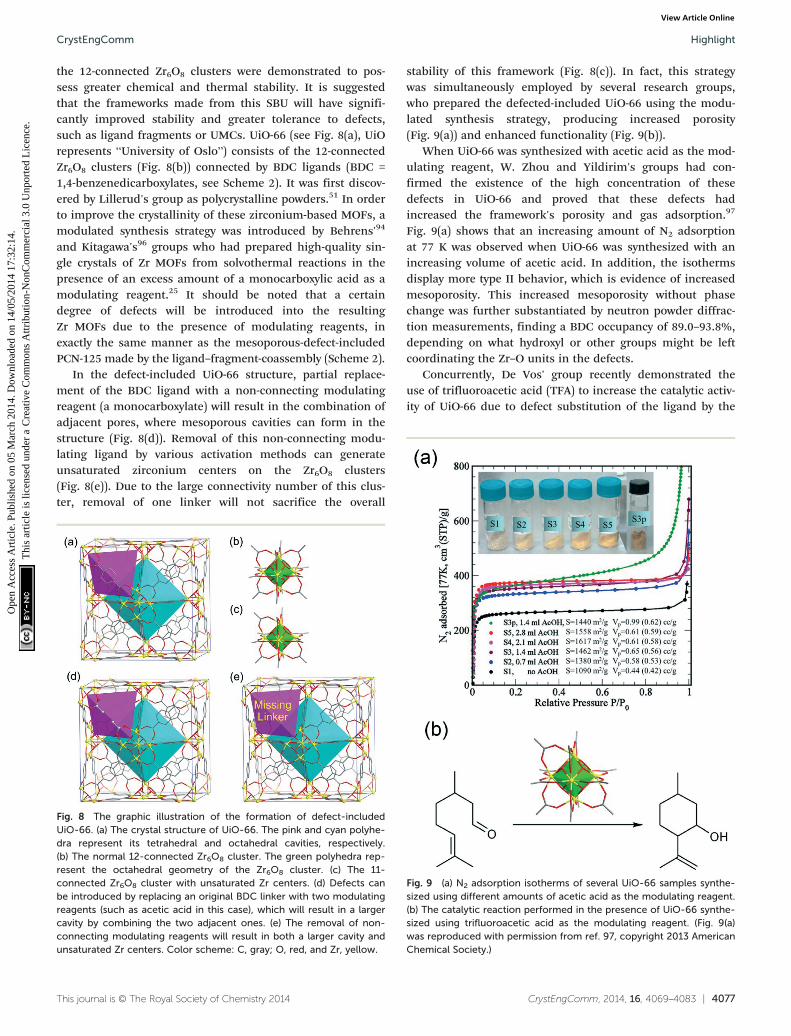
the 12-connected Zr6O8 clusters were demonstrated to pos-sess greater chemical and thermal stability. It is suggestedthat the frameworks made from this SBU will have signifi-cantly improved stability and greater tolerance to defects,such as ligand fragments or UMCs. UiO-66 (see Fig. 8(a), UiOrepresents “University of Oslo”) consists of the 12-connectedZr6O8 clusters (Fig. 8(b)) connected by BDC ligands (BDC =1,4-benzenedicarboxylates, see Scheme 2). It was first discov-ered by Lillerud's group as polycrystalline powders.51 In orderto improve the crystallinity of these zirconium-based MOFs, amodulated synthesis strategy was introduced by Behrens'94
and Kitagawa's96 groups who had prepared high-quality sin-gle crystals of Zr MOFs from solvothermal reactions in thepresence of an excess amount of a monocarboxylic acid as amodulating reagent.25 It should be noted that a certaindegree of defects will be introduced into the resultingZr MOFs due to the presence of modulating reagents, inexactly the same manner as the mesoporous-defect-includedPCN-125 made by the ligand–fragment-coassembly (Scheme 2).
In the defect-included UiO-66 structure, partial replace-ment of the BDC ligand with a non-connecting modulatingreagent (a monocarboxylate) will result in the combination ofadjacent pores, where mesoporous cavities can form in thestructure (Fig. 8(d)). Removal of this non-connecting modu-lating ligand by various activation methods can generateunsaturated zirconium centers on the Zr6O8 clusters(Fig. 8(e)). Due to the large connectivity number of this clus-ter, removal of one linker will not sacrifice the overall
This journal is © The Royal Society of Chemistry 2014
Fig. 8 The graphic illustration of the formation of defect-includedUiO-66. (a) The crystal structure of UiO-66. The pink and cyan polyhe-dra represent its tetrahedral and octahedral cavities, respectively.(b) The normal 12-connected Zr6O8 cluster. The green polyhedra rep-resent the octahedral geometry of the Zr6O8 cluster. (c) The 11-connected Zr6O8 cluster with unsaturated Zr centers. (d) Defects canbe introduced by replacing an original BDC linker with two modulatingreagents (such as acetic acid in this case), which will result in a largercavity by combining the two adjacent ones. (e) The removal of non-connecting modulating reagents will result in both a larger cavity andunsaturated Zr centers. Color scheme: C, gray; O, red, and Zr, yellow.
stability of this framework (Fig. 8(c)). In fact, this strategywas simultaneously employed by several research groups,who prepared the defected-included UiO-66 using the modu-lated synthesis strategy, producing increased porosity(Fig. 9(a)) and enhanced functionality (Fig. 9(b)).
When UiO-66 was synthesized with acetic acid as the mod-ulating reagent, W. Zhou and Yildirim's groups had con-firmed the existence of the high concentration of thesedefects in UiO-66 and proved that these defects hadincreased the framework's porosity and gas adsorption.97
Fig. 9(a) shows that an increasing amount of N2 adsorptionat 77 K was observed when UiO-66 was synthesized with anincreasing volume of acetic acid. In addition, the isothermsdisplay more type II behavior, which is evidence of increasedmesoporosity. This increased mesoporosity without phasechange was further substantiated by neutron powder diffrac-tion measurements, finding a BDC occupancy of 89.0–93.8%,depending on what hydroxyl or other groups might be leftcoordinating the Zr–O units in the defects.
Concurrently, De Vos' group recently demonstrated theuse of trifluoroacetic acid (TFA) to increase the catalytic activ-ity of UiO-66 due to defect substitution of the ligand by the
CrystEngComm, 2014, 16, 4069–4083 | 4077
Fig. 9 (a) N2 adsorption isotherms of several UiO-66 samples synthe-sized using different amounts of acetic acid as the modulating reagent.(b) The catalytic reaction performed in the presence of UiO-66 synthe-sized using trifluoroacetic acid as the modulating reagent. (Fig. 9(a)was reproduced with permission from ref. 97, copyright 2013 AmericanChemical Society.)
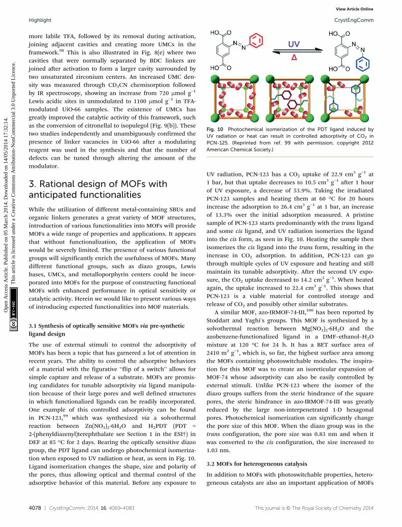
Fig. 10 Photochemical isomerization of the PDT ligand induced byUV radiation or heat can result in controlled adsorptivity of CO2 inPCN-125. (Reprinted from ref. 99 with permission, copyright 2012American Chemical Society.)
CrystEngCommHighlight
Ope
n A
cces
s A
rtic
le. P
ublis
hed
on 0
5 M
arch
201
4. D
ownl
oade
d on
14/
05/2
014
17:3
2:14
. T
his
artic
le is
lice
nsed
und
er a
Cre
ativ
e C
omm
ons
Attr
ibut
ion-
Non
Com
mer
cial
3.0
Unp
orte
d L
icen
ce.
View Article Online
more labile TFA, followed by its removal during activation,joining adjacent cavities and creating more UMCs in theframework.98 This is also illustrated in Fig. 8(e) where twocavities that were normally separated by BDC linkers arejoined after activation to form a larger cavity surrounded bytwo unsaturated zirconium centers. An increased UMC den-sity was measured through CD3CN chemisorption followedby IR spectroscopy, showing an increase from 720 μmol g−1
Lewis acidic sites in unmodulated to 1100 μmol g−1 in TFA-modulated UiO-66 samples. The existence of UMCs hasgreatly improved the catalytic activity of this framework, suchas the conversion of citronellal to isopulegol (Fig. 9(b)). Thesetwo studies independently and unambiguously confirmed thepresence of linker vacancies in UiO-66 after a modulatingreagent was used in the synthesis and that the number ofdefects can be tuned through altering the amount of themodulator.
3. Rational design of MOFs withanticipated functionalities
While the utilization of different metal-containing SBUs andorganic linkers generates a great variety of MOF structures,introduction of various functionalities into MOFs will provideMOFs a wide range of properties and applications. It appearsthat without functionalization, the application of MOFswould be severely limited. The presence of various functionalgroups will significantly enrich the usefulness of MOFs. Manydifferent functional groups, such as diazo groups, Lewisbases, UMCs, and metalloporphyrin centers could be incor-porated into MOFs for the purpose of constructing functionalMOFs with enhanced performance in optical sensitivity orcatalytic activity. Herein we would like to present various waysof introducing expected functionalities into MOF materials.
3.1 Synthesis of optically sensitive MOFs via pre-syntheticligand design
The use of external stimuli to control the adsorptivity ofMOFs has been a topic that has garnered a lot of attention inrecent years. The ability to control the adsorptive behaviorsof a material with the figurative “flip of a switch” allows forsimple capture and release of a substrate. MOFs are promis-ing candidates for tunable adsorptivity via ligand manipula-tion because of their large pores and well defined structuresin which functionalized ligands can be readily incorporated.One example of this controlled adsorptivity can be foundin PCN-123,99 which was synthesized via a solvothermalreaction between Zn(NO3)2·6H2O and H2PDT (PDT =2-(phenyldiazenyl)terephthalate see Section 1 in the ESI†) inDEF at 85 °C for 2 days. Bearing the optically sensitive diazogroup, the PDT ligand can undergo photochemical isomeriza-tion when exposed to UV radiation or heat, as seen in Fig. 10.Ligand isomerization changes the shape, size and polarity ofthe pores, thus allowing optical and thermal control of theadsorptive behavior of this material. Before any exposure to
4078 | CrystEngComm, 2014, 16, 4069–4083
UV radiation, PCN-123 has a CO2 uptake of 22.9 cm3 g−1 at1 bar, but that uptake decreases to 10.5 cm3 g−1 after 1 hourof UV exposure, a decrease of 53.9%. Taking the irradiatedPCN-123 samples and heating them at 60 °C for 20 hoursincrease the adsorption to 26.4 cm3 g−1 at 1 bar, an increaseof 13.3% over the initial adsorption measured. A pristinesample of PCN-123 starts predominantly with the trans ligandand some cis ligand, and UV radiation isomerizes the ligandinto the cis form, as seen in Fig. 10. Heating the sample thenisomerizes the cis ligand into the trans form, resulting in theincrease in CO2 adsorption. In addition, PCN-123 can gothrough multiple cycles of UV exposure and heating and stillmaintain its tunable adsorptivity. After the second UV expo-sure, the CO2 uptake decreased to 14.2 cm3 g−1. When heatedagain, the uptake increased to 22.4 cm3 g−1. This shows thatPCN-123 is a viable material for controlled storage andrelease of CO2 and possibly other similar substrates.
A similar MOF, azo-IRMOF-74-III,100 has been reported byStoddart and Yaghi's groups. This MOF is synthesized by asolvothermal reaction between Mg(NO3)2·6H2O and theazobenzene-functionalized ligand in a DMF–ethanol–H2Omixture at 120 °C for 24 h. It has a BET surface area of2410 m2 g−1, which is, so far, the highest surface area amongthe MOFs containing photoswitchable modules. The inspira-tion for this MOF was to create an isoreticular expansion ofMOF-74 whose adsorptivity can also be easily controlled byexternal stimuli. Unlike PCN-123 where the isomer of thediazo groups suffers from the steric hindrance of the squarepores, the steric hindrance in azo-IRMOF-74-III was greatlyreduced by the large non-interpenetrated 1-D hexagonalpores. Photochemical isomerization can significantly changethe pore size of this MOF. When the diazo group was in thetrans configuration, the pore size was 0.83 nm and when itwas converted to the cis configuration, the size increased to1.03 nm.
3.2 MOFs for heterogeneous catalysis
In addition to MOFs with photoswitchable properties, hetero-geneous catalysts are also an important application of MOFs
This journal is © The Royal Society of Chemistry 2014
CrystEngComm Highlight
Ope
n A
cces
s A
rtic
le. P
ublis
hed
on 0
5 M
arch
201
4. D
ownl
oade
d on
14/
05/2
014
17:3
2:14
. T
his
artic
le is
lice
nsed
und
er a
Cre
ativ
e C
omm
ons
Attr
ibut
ion-
Non
Com
mer
cial
3.0
Unp
orte
d L
icen
ce.
View Article Online
where ligand design is of vital importance. MOFs are excel-lent candidates as catalysts because it is convenient to incor-porate and distribute different catalytic centers into thestructure. MOFs have an advantage over homogeneous cata-lysts because of the convenient loading and separation pro-cess from the reaction mixture. Herein, a few representativesof catalytically active MOFs made from pre-synthetic liganddesign will be discussed in this section.
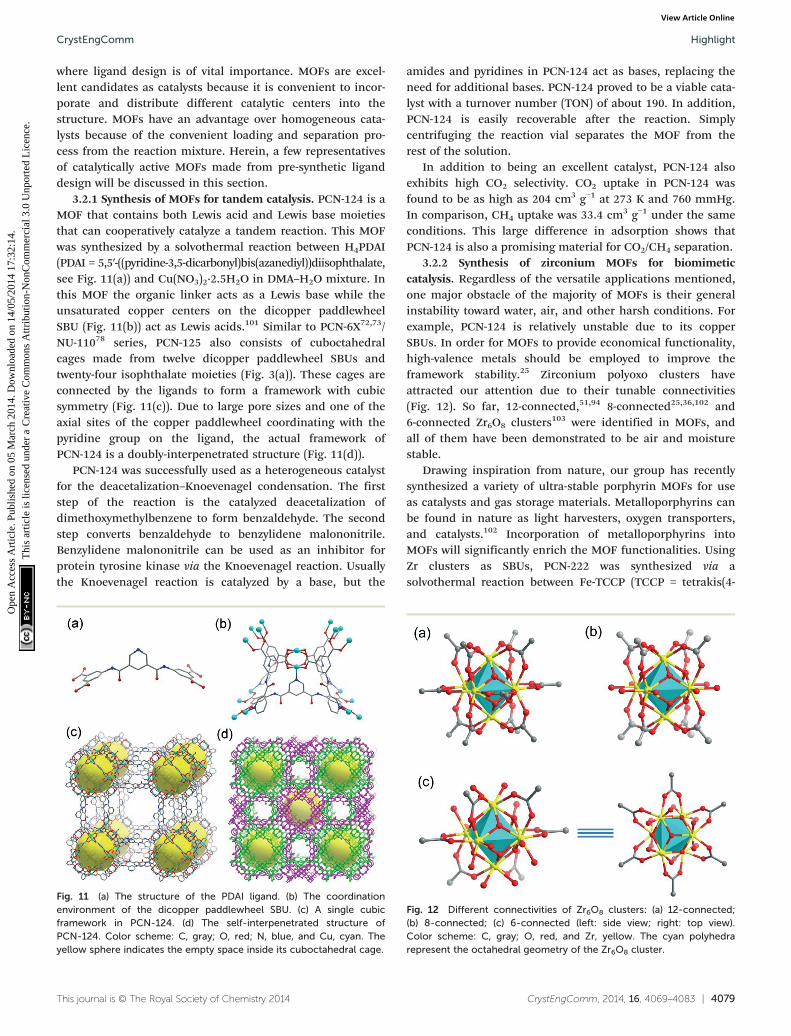
3.2.1 Synthesis of MOFs for tandem catalysis. PCN-124 is aMOF that contains both Lewis acid and Lewis base moietiesthat can cooperatively catalyze a tandem reaction. This MOFwas synthesized by a solvothermal reaction between H4PDAI(PDAI = 5,5′-((pyridine-3,5-dicarbonyl)bis(azanediyl))diisophthalate,see Fig. 11(a)) and Cu(NO3)2·2.5H2O in DMA–H2O mixture. Inthis MOF the organic linker acts as a Lewis base while theunsaturated copper centers on the dicopper paddlewheelSBU (Fig. 11(b)) act as Lewis acids.101 Similar to PCN-6X72,73/NU-11078 series, PCN-125 also consists of cuboctahedralcages made from twelve dicopper paddlewheel SBUs andtwenty-four isophthalate moieties (Fig. 3(a)). These cages areconnected by the ligands to form a framework with cubicsymmetry (Fig. 11(c)). Due to large pore sizes and one of theaxial sites of the copper paddlewheel coordinating with thepyridine group on the ligand, the actual framework ofPCN-124 is a doubly-interpenetrated structure (Fig. 11(d)).
PCN-124 was successfully used as a heterogeneous catalystfor the deacetalization–Knoevenagel condensation. The firststep of the reaction is the catalyzed deacetalization ofdimethoxymethylbenzene to form benzaldehyde. The secondstep converts benzaldehyde to benzylidene malononitrile.Benzylidene malononitrile can be used as an inhibitor forprotein tyrosine kinase via the Knoevenagel reaction. Usuallythe Knoevenagel reaction is catalyzed by a base, but the
This journal is © The Royal Society of Chemistry 2014
Fig. 11 (a) The structure of the PDAI ligand. (b) The coordinationenvironment of the dicopper paddlewheel SBU. (c) A single cubicframework in PCN-124. (d) The self-interpenetrated structure ofPCN-124. Color scheme: C, gray; O, red; N, blue, and Cu, cyan. Theyellow sphere indicates the empty space inside its cuboctahedral cage.
amides and pyridines in PCN-124 act as bases, replacing theneed for additional bases. PCN-124 proved to be a viable cata-lyst with a turnover number (TON) of about 190. In addition,PCN-124 is easily recoverable after the reaction. Simplycentrifuging the reaction vial separates the MOF from therest of the solution.
In addition to being an excellent catalyst, PCN-124 alsoexhibits high CO2 selectivity. CO2 uptake in PCN-124 wasfound to be as high as 204 cm3 g−1 at 273 K and 760 mmHg.In comparison, CH4 uptake was 33.4 cm3 g−1 under the sameconditions. This large difference in adsorption shows thatPCN-124 is also a promising material for CO2/CH4 separation.
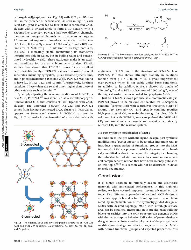
3.2.2 Synthesis of zirconium MOFs for biomimeticcatalysis. Regardless of the versatile applications mentioned,one major obstacle of the majority of MOFs is their generalinstability toward water, air, and other harsh conditions. Forexample, PCN-124 is relatively unstable due to its copperSBUs. In order for MOFs to provide economical functionality,high-valence metals should be employed to improve theframework stability.25 Zirconium polyoxo clusters haveattracted our attention due to their tunable connectivities(Fig. 12). So far, 12-connected,51,94 8-connected25,36,102 and6-connected Zr6O8 clusters103 were identified in MOFs, andall of them have been demonstrated to be air and moisturestable.
Drawing inspiration from nature, our group has recentlysynthesized a variety of ultra-stable porphyrin MOFs for useas catalysts and gas storage materials. Metalloporphyrins canbe found in nature as light harvesters, oxygen transporters,and catalysts.102 Incorporation of metalloporphyrins intoMOFs will significantly enrich the MOF functionalities. UsingZr clusters as SBUs, PCN-222 was synthesized via asolvothermal reaction between Fe-TCCP (TCCP = tetrakis(4-
CrystEngComm, 2014, 16, 4069–4083 | 4079
Fig. 12 Different connectivities of Zr6O8 clusters: (a) 12-connected;(b) 8-connected; (c) 6-connected (left: side view; right: top view).Color scheme: C, gray; O, red, and Zr, yellow. The cyan polyhedrarepresent the octahedral geometry of the Zr6O8 cluster.
Scheme 3 (a) The biomimetic reaction catalyzed by PCN-222 (b) TheCO2/epoxide coupling reaction catalyzed by PCN-224.
CrystEngCommHighlight
Ope
n A
cces
s A
rtic
le. P
ublis
hed
on 0
5 M
arch
201
4. D
ownl
oade
d on
14/
05/2
014
17:3
2:14
. T
his
artic
le is
lice
nsed
und
er a
Cre
ativ
e C
omm
ons
Attr
ibut
ion-
Non
Com
mer
cial
3.0
Unp
orte
d L
icen
ce.
View Article Online
carboxyphenyl)porphyrin, see Fig. 13) with ZrCl4 in DMF orDEF in the presence of benzoic acid. As seen in Fig. 13, eachFe-TCCP ligand is attached to four of the 8-connected Zr6O8
clusters with a twisted angle to form a 3D network with aKagome-like topology. PCN-222 has two different channels,mesoporous hexagonal channels with diameters as large as3.7 nm and microporous triangular channels with a diameterof 1.3 nm. It has a N2 uptake of 1009 cm3 g−1 and a BET sur-face area of 2200 m2 g−1. In addition to its large pore size,PCN-222 is incredibly stable, maintaining its frameworkintegrity not only in water, but in boiling water and concen-trated hydrochloric acid. These attributes make it an excel-lent candidate for use as a biomimetic catalyst. Kineticstudies have shown that PCN-222 makes for an excellentperoxidase-like catalyst. PCN-222 was used to oxidize severalsubstrates, including pyrogallol, 3,3,5,5-tetramethylbenzidine,and o-phenylenediamine (Scheme 3(a)). PCN-222 was foundto have kcat of 16.1, 14.0, and 7.3 min−1, respectively, for thesereactions. These values are several times higher than those ofother catalysts such as hemin.104
By simply adjusting the reaction conditions of PCN-222, anew MOF, PCN-224,103 was identified as a metalloporphyrin-functionalized MOF that consists of TCPP ligands with Zr6O8
clusters. The difference between PCN-222 and PCN-224comes from having 6-connected Zr6O8 clusters in PCN-224 asopposed to 8-connected clusters in PCN-222, as seen inFig. 13. This results in the formation of square channels with
4080 | CrystEngComm, 2014, 16, 4069–4083
Fig. 13 The ligands, SBUs and crystallographic structures of PCN-222(top) and PCN-224 (bottom). Color scheme: C, gray; O, red; N, blue,and Zr, yellow.
a diameter of 1.9 nm in the structure of PCN-224. LikePCN-222, PCN-224 shows ultra-high stability in solutionsranging from pH = 0 to pH = 11, a great improvementover PCN-222 which is not stable under basic conditions.In addition to its stability, PCN-224 showed N2 uptake of790 cm3 g−1 and a BET surface area of 2600 m2 g−1, one ofthe highest surface areas reported for porphyrin MOFs.
Just as PCN-222 showed promise as a biomimetic catalyst,PCN-224 proved to be an excellent catalyst for CO2/epoxidecoupling (Scheme 3(b)) with a turnover frequency (TOF) ofaround 120. Normally CO2 and epoxide coupling requireshigh pressures of CO2 to maintain enough dissolved CO2 insolution. But with PCN-224, one can preload the MOF withCO2 and use it as a heterogeneous catalyst which steadilyreleases CO2 into the reaction system.
3.3 Post-synthetic modification of MOFs
In addition to the pre-synthetic ligand design, post-syntheticmodifications (PSMs) appear to be another important way tointroduce a great variety of functional groups into the MOFframework. PSM is a process in which the material is chemi-cally modified without damaging the integrity or changingthe infrastructure of its framework. In consideration of sev-eral comprehensive reviews that have been recently publishedon this topic,31,32 this section will not be discussed in detailto avoid redundancy.
Conclusions
It is highly desirable to rationally design and synthesizematerials with anticipated performance. In this highlightreview, we have covered important recent advances on thistopic. Two different approaches of rational MOF design, astructural approach and a functional approach, were elabo-rated. By implementation of the symmetry-guided design ofMOFs with desired topology, MOFs with ultrahigh surfacearea can be obtained. Incorporation of pre-designed buildingblocks or cavities into the MOF structure can generate MOFswith desired adsorptive behavior. Utilization of pre-syntheticallydesigned organic linkers and employment of the post-syntheticmodification strategy are efficient ways to construct MOFswith desired functional groups and expected properties. This
This journal is © The Royal Society of Chemistry 2014
CrystEngComm Highlight
Ope
n A
cces
s A
rtic
le. P
ublis
hed
on 0
5 M
arch
201
4. D
ownl
oade
d on
14/
05/2
014
17:3
2:14
. T
his
artic
le is
lice
nsed
und
er a
Cre
ativ
e C
omm
ons
Attr
ibut
ion-
Non
Com
mer
cial
3.0
Unp
orte
d L
icen
ce.
View Article Online
work also offers a general perspective of rational design ofMOFs with expected porosities and functionalities.
Acknowledgements
This work was supported as part of the Center for Gas Sepa-rations Relevant to Clean Energy Technologies, an EnergyFrontier Research Center funded by the U.S. Department ofEnergy (DOE), the Office of Science and the Office of BasicEnergy Sciences under award number DE-SC0001015, part ofthe Hydrogen and Fuel Cell Program under award numberDE-FC36-07G017033, part of the Methane Opportunities forVehicular Energy (MOVE) Program, an ARPA-e project underaward number DE-AR0000249 and part of the Welch Founda-tion under award number A-1725. M. B. also acknowledgesthe Texas A&M graduate merit fellowship.
Notes and references
1 H.-C. Zhou, J. R. Long and O. M. Yaghi, Chem. Rev., 2012,
112, 673–674.2 J. R. Long and O. M. Yaghi, Chem. Soc. Rev., 2009, 38,
1213–1214.3 S. R. Batten, N. R. Champness, X.-M. Chen,
J. Garcia-Martinez, S. Kitagawa, L. Öhrström, O. K. Michael,M. P. Suh and J. Reedijk, Pure Appl. Chem., 2013, 85,1715–1724.4 J. Sculley, D. Yuan and H.-C. Zhou, Energy Environ. Sci.,
2011, 4, 2721–2735.5 M. P. Suh, H. J. Park, T. K. Prasad and D.-W. Lim, Chem.
Rev., 2011, 112, 782–835.6 T. A. Makal, J.-R. Li, W. Lu and H.-C. Zhou, Chem. Soc. Rev.,
2012, 41, 7761–7779.7 E. D. Bloch, W. L. Queen, R. Krishna, J. M. Zadrozny,
C. M. Brown and J. R. Long, Science, 2012, 335, 1606–1610.8 J.-R. Li, R. J. Kuppler and H.-C. Zhou, Chem. Soc. Rev., 2009,
38, 1477–1504.9 J.-R. Li, J. Sculley and H.-C. Zhou, Chem. Rev., 2011, 112,
869–932.10 T. M. McDonald, W. R. Lee, J. A. Mason, B. M. Wiers,
C. S. Hong and J. R. Long, J. Am. Chem. Soc., 2012, 134,7056–7065.11 K. Sumida, D. L. Rogow, J. A. Mason, T. M. McDonald,
E. D. Bloch, Z. R. Herm, T.-H. Bae and J. R. Long,Chem. Rev., 2011, 112, 724–781.12 J.-R. Li, Y. Ma, M. C. McCarthy, J. Sculley, J. Yu,
H.-K. Jeong, P. B. Balbuena and H.-C. Zhou, Coord. Chem.Rev., 2011, 255, 1791–1823.13 L. Ma, C. Abney and W. Lin, Chem. Soc. Rev., 2009, 38,
1248–1256.14 M. Yoon, R. Srirambalaji and K. Kim, Chem. Rev., 2011,
112, 1196–1231.15 M. D. Allendorf, C. A. Bauer, R. K. Bhakta and
R. J. T. Houk, Chem. Soc. Rev., 2009, 38, 1330–1352.16 Y. Cui, Y. Yue, G. Qian and B. Chen, Chem. Rev., 2011, 112,
1126–1162.This journal is © The Royal Society of Chemistry 2014
17 P. Horcajada, T. Chalati, C. Serre, B. Gillet, C. Sebrie,
T. Baati, J. F. Eubank, D. Heurtaux, P. Clayette, C. Kreuz,J.-S. Chang, Y. K. Hwang, V. Marsaud, P.-N. Bories,L. Cynober, S. Gil, G. Ferey, P. Couvreur and R. Gref,Nat. Mater., 2010, 9, 172–178.18 P. Horcajada, R. Gref, T. Baati, P. K. Allan, G. Maurin,
P. Couvreur, G. Férey, R. E. Morris and C. Serre, Chem. Rev.,2011, 112, 1232–1268.19 H. Li, M. Eddaoudi, M. O'Keeffe and O. M. Yaghi, Nature,
1999, 402, 276–279.20 S. S.-Y. Chui, S. M.-F. Lo, J. P. H. Charmant, A. G. Orpen
and I. D. Williams, Science, 1999, 283, 1148–1150.21 H. Furukawa, K. E. Cordova, M. O'Keeffe and O. M. Yaghi,
Science, 2013, 341, 1230444.22 S. M. Kuznicki, V. A. Bell, S. Nair, H. W. Hillhouse,
R. M. Jacubinas, C. M. Braunbarth, B. H. Toby andM. Tsapatsis, Nature, 2001, 412, 720–724.23 B. Chen, S. Ma, F. Zapata, F. R. Fronczek, E. B. Lobkovsky
and H.-C. Zhou, Inorg. Chem., 2007, 46, 1233–1236.24 O. K. Farha and J. T. Hupp, Acc. Chem. Res., 2010, 43,
1166–1175.25 M. Zhang, Y.-P. Chen, M. Bosch, T. Gentle, K. Wang,
D. Feng, Z. U. Wang and H.-C. Zhou, Angew. Chem., Int. Ed.,2014, 53, 815–818.26 M. Wriedt, A. A. Yakovenko, G. J. Halder, A. V. Prosvirin,
K. R. Dunbar and H.-C. Zhou, J. Am. Chem. Soc., 2013, 135,4040–4050.27 M. Eddaoudi, J. Kim, N. Rosi, D. Vodak, J. Wachter,
M. O'Keeffe and O. M. Yaghi, Science, 2002, 295, 469–472.28 O. M. Yaghi, M. O'Keeffe, N. W. Ockwig, H. K. Chae,
M. Eddaoudi and J. Kim, Nature, 2003, 423, 705–714.29 D. Zhao, D. J. Timmons, D. Yuan and H.-C. Zhou, Acc.
Chem. Res., 2010, 44, 123–133.30 F. A. Almeida Paz, J. Klinowski, S. M. F. Vilela,
J. P. C. Tome, J. A. S. Cavaleiro and J. Rocha, Chem. Soc.Rev., 2012, 41, 1088–1110.31 Z. Wang and S. M. Cohen, Chem. Soc. Rev., 2009, 38, 1315–1329.
32 S. M. Cohen, Chem. Rev., 2011, 112, 970–1000. 33 X.-S. Wang, S. Ma, P. M. Forster, D. Yuan, J. Eckert,J. J. López, B. J. Murphy, J. B. Parise and H.-C. Zhou,Angew. Chem., Int. Ed., 2008, 47, 7263–7266.
34 D. Sun, Y. Ke, T. M. Mattox, B. A. Ooro and H.-C. Zhou,
Chem. Commun., 2005, 5447–5449.35 M. Zhang, Y.-P. Chen and H.-C. Zhou, CrystEngComm, 2013,
15, 9544–9552.36 W. Morris, B. Volosskiy, S. Demir, F. Gándara,
P. L. McGrier, H. Furukawa, D. Cascio, J. F. Stoddart andO. M. Yaghi, Inorg. Chem., 2012, 51, 6443–6445.37 S. Ma, D. Sun, M. Ambrogio, J. A. Fillinger, S. Parkin and
H.-C. Zhou, J. Am. Chem. Soc., 2007, 129, 1858–1859.38 T. A. Makal, A. A. Yakovenko and H.-C. Zhou, J. Phys. Chem.
Lett., 2011, 2, 1682–1689.39 H.-L. Jiang, T. A. Makal and H.-C. Zhou, Coord. Chem. Rev.,
2013, 257, 2232–2249.40 O. K. Farha, C. D. Malliakas, M. G. Kanatzidis and
J. T. Hupp, J. Am. Chem. Soc., 2009, 132, 950–952.CrystEngComm, 2014, 16, 4069–4083 | 4081
CrystEngCommHighlight
Ope
n A
cces
s A
rtic
le. P
ublis
hed
on 0
5 M
arch
201
4. D
ownl
oade
d on
14/
05/2
014
17:3
2:14
. T
his
artic
le is
lice
nsed
und
er a
Cre
ativ
e C
omm
ons
Attr
ibut
ion-
Non
Com
mer
cial
3.0
Unp
orte
d L
icen
ce.
View Article Online
41 M. O'Keeffe and O. M. Yaghi, Chem. Rev., 2011, 112,
675–702.42 V. A. Blatov, L. Carlucci, G. Ciani and D. M. Proserpio,
CrystEngComm, 2004, 6, 378–395.43 L. Carlucci, G. Ciani and D. M. Proserpio, Coord. Chem.
Rev., 2003, 246, 247–289.44 M. Li, D. Li, M. O'Keeffe and O. M. Yaghi, Chem. Rev., 2013,
114, 1343–1370.45 H. Chun, D. Kim, D. N. Dybtsev and K. Kim, Angew. Chem.,
Int. Ed., 2004, 43, 971–974.46 O. Delgado-Friedrichs, M. O'Keeffe and O. M. Yaghi, Acta
Crystallogr., Sect. A: Found. Crystallogr., 2006, 62, 350–355.47 O. Delgado-Friedrichs, M. O'Keeffe and O. M. Yaghi, Phys.
Chem. Chem. Phys., 2007, 9, 1035–1043.48 O. Delgado Friedrichs, M. O'Keeffe and O. M. Yaghi, Solid
State Sci., 2003, 5, 73–78.49 T. Muller and S. Brase, RSC Adv., 2014, 4, 6886–6907.
50 S. R. Taylor, Geochim. Cosmochim. Acta, 1964, 28, 1273–1285. 51 J. H. Cavka, S. Jakobsen, U. Olsbye, N. Guillou, C. Lamberti,S. Bordiga and K. P. Lillerud, J. Am. Chem. Soc., 2008, 130,13850–13851.
52 L. Ma, A. Jin, Z. Xie and W. Lin, Angew. Chem., Int. Ed.,
2009, 48, 9905–9908.53 L. Wen, P. Cheng and W. Lin, Chem. Sci., 2012, 3, 2288–2292.
54 L. Wen, P. Cheng and W. Lin, Chem. Commun., 2012, 48,2846–2848.55 M. Dinca, A. Dailly, Y. Liu, C. M. Brown, D. A. Neumann
and J. R. Long, J. Am. Chem. Soc., 2006, 128, 16876–16883.56 M. Dinca, A. Dailly and J. R. Long, Chem. – Eur. J., 2008, 14,
10280–10285.57 I. Timokhin, J. Baguna Torres, A. J. P. White, P. D. Lickiss,
C. Pettinari and R. P. Davies, Dalton Trans., 2013, 42,13806–13808.
58 J. M. Gotthardt, K. F. White, B. F. Abrahams, C. Ritchie and
C. Boskovic, Cryst. Growth Des., 2012, 12, 4425–4430.59 Y.-S. Xue, L. Zhou, M.-P. Liu, S.-M. Liu, Y. Xu, H.-B. Du and
X.-Z. You, CrystEngComm, 2013, 15, 6229–6236.60 Y. E. Cheon and M. P. Suh, Chem. Commun., 2009,
2296–2298.61 J. Tian, R. K. Motkuri, P. K. Thallapally and B. P. McGrail,
Cryst. Growth Des., 2010, 10, 5327–5333.62 T.-F. Liu, J. Lü, C. Tian, M. Cao, Z. Lin and R. Cao, Inorg.
Chem., 2011, 50, 2264–2271.63 J. Tian, L. V. Saraf, B. Schwenzer, S. M. Taylor,
E. K. Brechin, J. Liu, S. J. Dalgarno and P. K. Thallapally,J. Am. Chem. Soc., 2012, 134, 9581–9584.64 L.-L. Liang, S.-B. Ren, J. Wang, J. Zhang, Y.-Z. Li, H.-B. Du
and X.-Z. You, CrystEngComm, 2010, 12, 2669–2671.65 Y.-X. Li, M. Xue, L. Huang, S.-R. Chen and S.-L. Qiu, Chem.
Res. Chin. Univ., 2013, 29, 611–616.66 F. Nouar, J. F. Eubank, T. Bousquet, L. Wojtas,
M. J. Zaworotko and M. Eddaoudi, J. Am. Chem. Soc., 2008,130, 1833–1835.67 G. K. H. Shimizu, Nat. Chem., 2010, 2, 909–911.
68 M. Eddaoudi, J. Kim, J. B. Wachter, H. K. Chae, M. O'Keeffeand O. M. Yaghi, J. Am. Chem. Soc., 2001, 123, 4368–4369.
4082 | CrystEngComm, 2014, 16, 4069–4083
69 J.-R. Li, A. A. Yakovenko, W. Lu, D. J. Timmons, W. Zhuang,
D. Yuan and H.-C. Zhou, J. Am. Chem. Soc., 2010, 132,17599–17610.70 J.-R. Li and H.-C. Zhou, Nat. Chem., 2010, 2, 893–898.
71 M. Zhang, W. Lu, J.-R. Li, M. Bosch, Y.-P. Chen, T.-F. Liu,Y. Liu and H.-C. Zhou, Inorg. Chem. Front., 2014, 1,159–162.
72 D. Zhao, D. Yuan, D. Sun and H.-C. Zhou, J. Am. Chem.
Soc., 2009, 131, 9186–9188.73 D. Yuan, D. Zhao, D. Sun and H.-C. Zhou, Angew. Chem.,
Int. Ed., 2010, 49, 5357–5361.74 Y. Yan, X. Lin, S. Yang, A. J. Blake, A. Dailly,
N. R. Champness, P. Hubberstey and M. Schroder, Chem.Commun., 2009, 1025–1027.75 Y. Yan, I. Telepeni, S. Yang, X. Lin, W. Kockelmann,
A. Dailly, A. J. Blake, W. Lewis, G. S. Walker, D. R. Allan,S. A. Barnett, N. R. Champness and M. Schröder, J. Am.Chem. Soc., 2010, 132, 4092–4094.76 Y. Yan, S. Yang, A. J. Blake, W. Lewis, E. Poirier,
S. A. Barnett, N. R. Champness and M. Schroder, Chem.Commun., 2011, 47, 9995–9997.77 O. K. Farha, A. Özgür Yazaydın, I. Eryazici, C. D. Malliakas,
B. G. Hauser, M. G. Kanatzidis, S. T. Nguyen, R. Q. Snurrand J. T. Hupp, Nat. Chem., 2010, 2, 944–948.78 O. K. Farha, I. Eryazici, N. C. Jeong, B. G. Hauser,
C. E. Wilmer, A. A. Sarjeant, R. Q. Snurr, S. T. Nguyen,A. Ö. Yazaydın and J. T. Hupp, J. Am. Chem. Soc., 2012, 134,15016–15021.79 W. Lu, D. Yuan, T. A. Makal, J.-R. Li and H.-C. Zhou, Angew.
Chem., Int. Ed., 2012, 51, 1580–1584.80 W. Lu, D. Yuan, T. A. Makal, Z. Wei, J.-R. Li and
H.-C. Zhou, Dalton Trans., 2013, 42, 1708–1714.81 J.-R. Li, J. Yu, W. Lu, L.-B. Sun, J. Sculley, P. B. Balbuena
and H.-C. Zhou, Nat. Commun., 2013, 4, 1538.82 Z. J. Zhang, Y. G. Zhao, Q. H. Gong, Z. Li and J. Li, Chem.
Commun., 2013, 49, 653–661.83 M. Zhang, Z. Perry, J. Park and H.-C. Zhou, Polymer, 2014,
55, 335–339.84 P. D. C. Dietzel, R. Blom and H. Fjellvåg, Eur. J. Inorg.
Chem., 2008, 2008, 3624–3632.85 D. Britt, H. Furukawa, B. Wang, T. G. Glover and
O. M. Yaghi, Proc. Natl. Acad. Sci. U. S. A., 2009, 106,20637–20640.86 D.-A. Yang, H.-Y. Cho, J. Kim, S.-T. Yang and W.-S. Ahn,
Energy Environ. Sci., 2012, 5, 6465–6473.87 A. R. Millward and O. M. Yaghi, J. Am. Chem. Soc., 2005,
127, 17998–17999.88 S. R. Caskey, A. G. Wong-Foy and A. J. Matzger, J. Am.
Chem. Soc., 2008, 130, 10870–10871.89 M. Wriedt, J. P. Sculley, A. A. Yakovenko, Y. Ma,
G. J. Halder, P. B. Balbuena and H.-C. Zhou, Angew. Chem.,Int. Ed., 2012, 51, 9804–9808.90 H. Wu, J. M. Simmons, Y. Liu, C. M. Brown, X. S. Wang,
S. Ma, V. K. Peterson, P. D. Southon, C. J. Kepert,H. C. Zhou, T. Yildirim and W. Zhou, Chem. – Eur. J., 2010,16, 5205–5214.This journal is © The Royal Society of Chemistry 2014
CrystEngComm Highlight
Ope
n A
cces
s A
rtic
le. P
ublis
hed
on 0
5 M
arch
201
4. D
ownl
oade
d on
14/
05/2
014
17:3
2:14
. T
his
artic
le is
lice
nsed
und
er a
Cre
ativ
e C
omm
ons
Attr
ibut
ion-
Non
Com
mer
cial
3.0
Unp
orte
d L
icen
ce.
View Article Online
91 H. Wu, Q. Gong, D. H. Olson and J. Li, Chem. Rev., 2012,
112, 836–868.92 Z. R. Herm, B. M. Wiers, J. A. Mason, J. M. van Baten,
M. R. Hudson, P. Zajdel, C. M. Brown, N. Masciocchi,R. Krishna and J. R. Long, Science, 2013, 340, 960–964.93 J. Park, Z. U. Wang, L.-B. Sun, Y.-P. Chen and H.-C. Zhou,
J. Am. Chem. Soc., 2012, 134, 20110–20116.94 A. Schaate, P. Roy, A. Godt, J. Lippke, F. Waltz, M. Wiebcke
and P. Behrens, Chem. – Eur. J., 2011, 17, 6643–6651.95 X. Lin, I. Telepeni, A. J. Blake, A. Dailly, C. M. Brown,
J. M. Simmons, M. Zoppi, G. S. Walker, K. M. Thomas,T. J. Mays, P. Hubberstey, N. R. Champness andM. Schroder, J. Am. Chem. Soc., 2009, 131, 2159–2171.96 T. Tsuruoka, S. Furukawa, Y. Takashima, K. Yoshida,
S. Isoda and S. Kitagawa, Angew. Chem., Int. Ed., 2009, 48,4739–4743.97 H. Wu, Y. S. Chua, V. Krungleviciute, M. Tyagi, P. Chen,
T. Yildirim and W. Zhou, J. Am. Chem. Soc., 2013, 135,10525–10532.This journal is © The Royal Society of Chemistry 2014
98 F. Vermoortele, B. Bueken, G. Le Bars, B. Van de Voorde,
M. Vandichel, K. Houthoofd, A. Vimont, M. Daturi,M. Waroquier, V. Van Speybroeck, C. Kirschhock andD. E. De Vos, J. Am. Chem. Soc., 2013, 135, 11465–11468.99 J. Park, D. Yuan, K. T. Pham, J.-R. Li, A. Yakovenko and
H.-C. Zhou, J. Am. Chem. Soc., 2011, 134, 99–102.100 J. W. Brown, B. L. Henderson, M. D. Kiesz, A. C. Whalley,
W. Morris, S. Grunder, H. Deng, H. Furukawa, J. I. Zink,J. F. Stoddart and O. M. Yaghi, Chem. Sci., 2013, 4, 2858–2864.101 J. Park, J.-R. Li, Y.-P. Chen, J. Yu, A. A. Yakovenko,
Z. U. Wang, L.-B. Sun, P. B. Balbuena and H.-C. Zhou,Chem. Commun., 2012, 48, 9995–9997.102 D. Feng, Z.-Y. Gu, J.-R. Li, H.-L. Jiang, Z. Wei and
H.-C. Zhou, Angew. Chem., Int. Ed., 2012, 51, 10307–10310.103 D. Feng, W.-C. Chung, Z. Wei, Z.-Y. Gu, H.-L. Jiang,
Y.-P. Chen, D. J. Darensbourg and H.-C. Zhou, J. Am. Chem.Soc., 2013, 135, 17105–17110.104 Q. Wang, Z. Yang, X. Zhang, X. Xiao, C. K. Chang and
B. Xu, Angew. Chem., Int. Ed., 2007, 46, 4285–4289.CrystEngComm, 2014, 16, 4069–4083 | 4083