Embed Size (px)
Citation preview
Rational Method Hydrologic Calculations with Excel Course No: C02-039
Credit: 2 PDH
Harlan H. Bengtson, PhD, P.E.
Continuing Education and Development, Inc. 9 Greyridge Farm Court Stony Point, NY 10980 P: (877) 322-5800 F: (877) 322-4774 [email protected]
Rational Method Hydrologic Calculations with Excel
Harlan H. Bengtson, PhD, P.E.
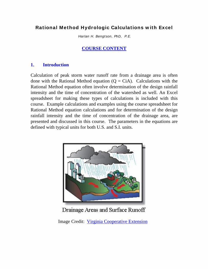
COURSE CONTENT 1. Introduction Calculation of peak storm water runoff rate from a drainage area is often done with the Rational Method equation (Q = CiA). Calculations with the Rational Method equation often involve determination of the design rainfall intensity and the time of concentration of the watershed as well. An Excel spreadsheet for making these types of calculations is included with this course. Example calculations and examples using the course spreadsheet for Rational Method equation calculations and for determination of the design rainfall intensity and the time of concentration of the drainage area, are presented and discussed in this course. The parameters in the equations are defined with typical units for both U.S. and S.I. units.
Image Credit: Virginia Cooperative Extension
2. Learning Objectives At the conclusion of this course, the student will
• Know the parameters and their U.S. and S.I. units to be used in the Rational Method equation
• Be able to calculate peak storm water runoff rate with the Rational
Method equation, using either U.S. or S.I. units
• Be able to place a given soil into one of the four SCS soil groups based on its measured minimum infiltration rate
• Be able to place a given soil into one of the four SCS soil groups
based on its description
• Be able to determine a value of the Rational Method runoff coefficient based on land use, soil group, and slope of the watershed
• Be able to calculate the overland sheet flow travel time for a
watershed using the Manning Kinematic equation
• Be able to calculate the shallow concentrated flow travel time for a watershed using the NRCS method
• Be able to calculate the open channel flow travel time for a watershed
using the Manning equation
• Know the form of the equation used for rainfall intensity as a function of storm duration for a specified return period.
• Be able to use Excel spreadsheets to make the types of calculations
discussed in this course. 3. Topics Covered in this Course I. The Rational Method Equation
II. Runoff Coefficients III. Watershed Time of Concentration IV. Design Rainfall Intensity V. Peak Storm Water Runoff Rate Calculations VI. The Steel Equation for Design Rainfall Intensity VI. Summary VII. References 4. The Rational Method Equation The Rational Method equation actually used to calculate peak storm water runoff rate is: Q = CiA (U.S. units), or Q = 0.0028 CiA (S.I. units) where:
• A = the area of the watershed (drainage area) that drains to the point for which the peak runoff rate is needed (acres for U.S. units) (ha for S.I. units)
• C = runoff coefficient for drainage area A. A physical interpretation
is the faction of rainfall landing on the drainage area that becomes storm water runoff. (dimensionless for both U.S. and S.I. units)
• i = the intensity of the design storm for peak runoff calculation
(in/hr for U.S. units) (mm/hr for S.I. units) • Q = the peak storm water runoff rate from the drainage area, A, due
to the design storm of intensity, i. (cfs for U.S. units) ( m3/s for S.I. units).
Explanation of Units: For the SI version of the equation (Q = 0.0028 CiA), the 0.0028 factor is needed to convert ha to m, mm to m, and hr to sec as follows: Q = (mm/hr)(ha)(10,000 m2/ha)(1 m/1000 mm)(1 hr/3600 sec), or Q = 0.0028 CiA, with i in mm/hr, A in ha, and Q in m3/s At first glance the units don't appear to be correct for the specified U.S. units. The equation actually gives Q in acre-in/hr. The conversion factor, however, is 1.008 cfs/(acre-in/hr), and based on the precision with which the runoff coefficient can be determined, this conversion is typically taken to be 1, thus giving Q in cfs for rainfall intensity in in/hr and drainage area in acres. The calculation of peak storm water runoff rate from the equation, Q = CiA, is quite straightforward if values are known for C, i, and A. Values for the drainage area, A, and the runoff coefficient, C, can typically be obtained without much trouble. Determination of the design rainfall intensity, i, usually requires the most effort. Example #1: Calculate the peak storm water runoff rate from a watershed of 15 acres, with a runoff coefficient of 0.35, from a storm of intensity 2.4 in/hr. Solution: This requires simply substituting into the equation ( Q = CiA ), thus: Q = (0.35)(2.4)(15) = 12.6 cfs 5. Rational Method Runoff Coefficients Since the physical interpretation of the runoff coefficient is the fraction of the rainfall on the watershed that becomes surface runoff, it’s value must be between one and zero. The value of the runoff coefficient for a given drainage area depends primarily on three factors: i) the soil type, ii) the land use, and iii) the slope of the watershed. Each of those factors will now be discussed briefly.
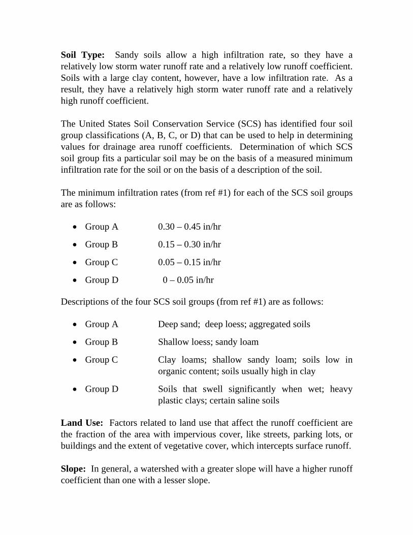
Soil Type: Sandy soils allow a high infiltration rate, so they have a relatively low storm water runoff rate and a relatively low runoff coefficient. Soils with a large clay content, however, have a low infiltration rate. As a result, they have a relatively high storm water runoff rate and a relatively high runoff coefficient. The United States Soil Conservation Service (SCS) has identified four soil group classifications (A, B, C, or D) that can be used to help in determining values for drainage area runoff coefficients. Determination of which SCS soil group fits a particular soil may be on the basis of a measured minimum infiltration rate for the soil or on the basis of a description of the soil. The minimum infiltration rates (from ref #1) for each of the SCS soil groups are as follows:
• Group A 0.30 – 0.45 in/hr
• Group B 0.15 – 0.30 in/hr
• Group C 0.05 – 0.15 in/hr
• Group D 0 – 0.05 in/hr Descriptions of the four SCS soil groups (from ref #1) are as follows:
• Group A Deep sand; deep loess; aggregated soils
• Group B Shallow loess; sandy loam
• Group C Clay loams; shallow sandy loam; soils low in organic content; soils usually high in clay
• Group D Soils that swell significantly when wet; heavy plastic clays; certain saline soils
Land Use: Factors related to land use that affect the runoff coefficient are the fraction of the area with impervious cover, like streets, parking lots, or buildings and the extent of vegetative cover, which intercepts surface runoff. Slope: In general, a watershed with a greater slope will have a higher runoff coefficient than one with a lesser slope.

The two tables below provide runoff coefficient values in terms of land use and watershed slope for each of the four SCS soil groups. As indicated below, the source for the information in the table is the Knox County Tennessee Stormwater Management Manual (Ref #2 at the end of the course). Example #2: What is the value of the runoff coefficient to be used in Rational Method equation calculations, for a residential area with ¼ acre lots, soil group B, and slope of approximately 1.4%? Solution: From Part I of the Runoff Coefficient Tables below, C = 0.33
Source: Knox County Tennessee, Stormwater Management Manual, http://www.knoxcounty.org/stormwater/pdfs/vol2/3-1-3%20Rational
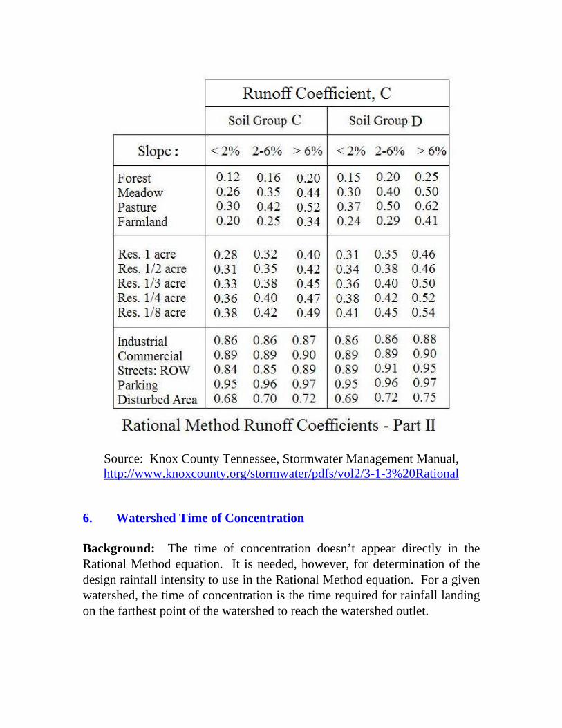
Source: Knox County Tennessee, Stormwater Management Manual, http://www.knoxcounty.org/stormwater/pdfs/vol2/3-1-3%20Rational
6. Watershed Time of Concentration Background: The time of concentration doesn’t appear directly in the Rational Method equation. It is needed, however, for determination of the design rainfall intensity to use in the Rational Method equation. For a given watershed, the time of concentration is the time required for rainfall landing on the farthest point of the watershed to reach the watershed outlet.
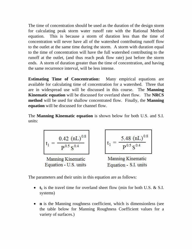
The time of concentration should be used as the duration of the design storm for calculating peak storm water runoff rate with the Rational Method equation. This is because a storm of duration less than the time of concentration will never have all of the watershed contributing runoff flow to the outlet at the same time during the storm. A storm with duration equal to the time of concentration will have the full watershed contributing to the runoff at the outlet, (and thus reach peak flow rate) just before the storm ends. A storm of duration greater than the time of concentration, and having the same recurrence interval, will be less intense. Estimating Time of Concentration: Many empirical equations are available for calculating time of concentration for a watershed. Three that are in widespread use will be discussed in this course. The Manning Kinematic equation will be discussed for overland sheet flow. The NRCS method will be used for shallow concentrated flow. Finally, the Manning equation will be discussed for channel flow. The Manning Kinematic equation is shown below for both U.S. and S.I. units:
The parameters and their units in this equation are as follows:
• t1 is the travel time for overland sheet flow (min for both U.S. & S.I. systems)
• n is the Manning roughness coefficient, which is dimensionless (see
the table below for Manning Roughness Coefficient values for a variety of surfaces.)
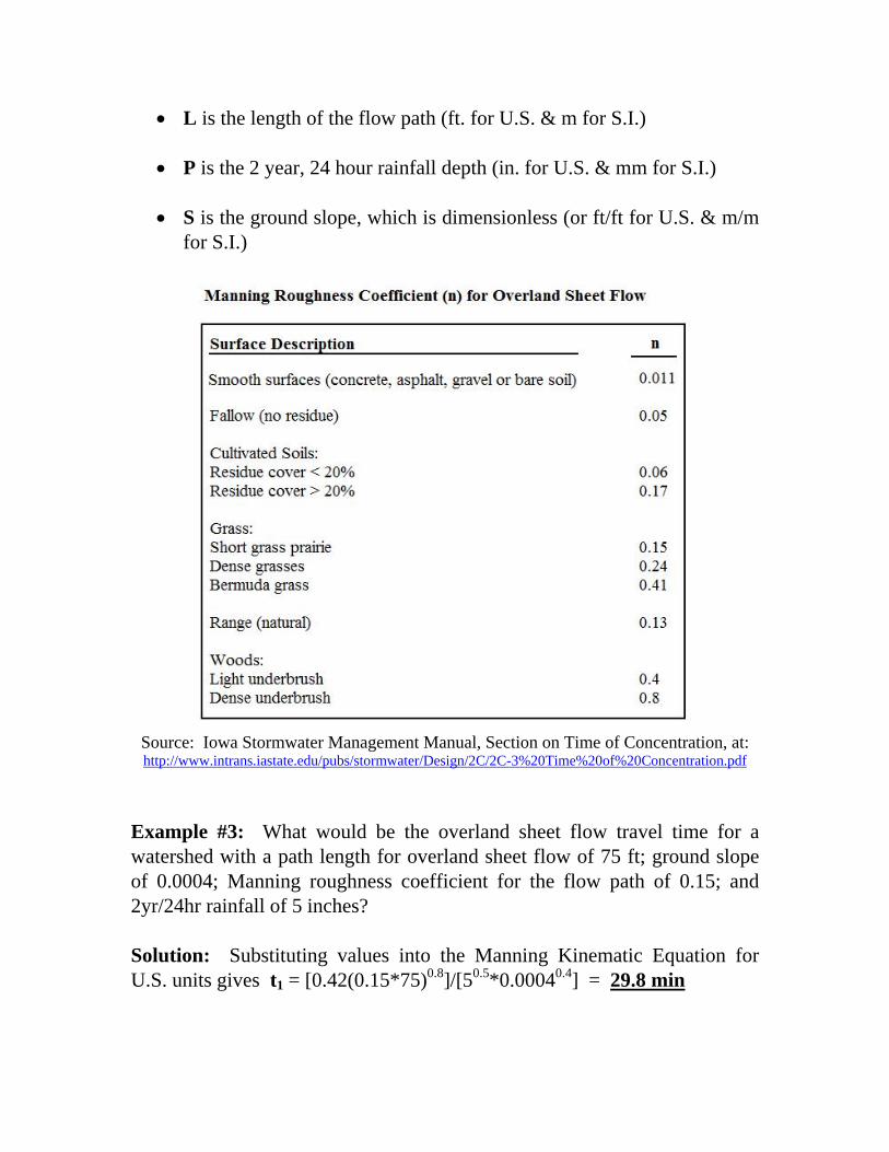
• L is the length of the flow path (ft. for U.S. & m for S.I.)
• P is the 2 year, 24 hour rainfall depth (in. for U.S. & mm for S.I.)
• S is the ground slope, which is dimensionless (or ft/ft for U.S. & m/m for S.I.)
Source: Iowa Stormwater Management Manual, Section on Time of Concentration, at: http://www.intrans.iastate.edu/pubs/stormwater/Design/2C/2C-3%20Time%20of%20Concentration.pdf
Example #3: What would be the overland sheet flow travel time for a watershed with a path length for overland sheet flow of 75 ft; ground slope of 0.0004; Manning roughness coefficient for the flow path of 0.15; and 2yr/24hr rainfall of 5 inches? Solution: Substituting values into the Manning Kinematic Equation for U.S. units gives t1 = [0.42(0.15*75)0.8]/[50.5*0.00040.4] = 29.8 min
The NRCS Method is recommended by and described in references #3 and #4 (Natural Resources Conservation Service and the Iowa Stormwater Management Manual) for the shallow concentrated flow that normally develops within 100 to 300 feet into the watershed, after overland sheet flow. The NRCS method involves calculation of the velocity of the shallow concentrated flow based on information about the slope and the type of surface. The travel time is then calculated as the travel length divided by the flow velocity. The equations used in NRCS Method calculations are as follows for U.S. units:
• V = 16.1345 S0.5 for an unpaved surface
• V = 20.3282 S0.5 for a paved surface
• t2 = L/(60V) For S.I. units, the NRCS Method equations are:
• V = 4.9178 S0.5 for an unpaved surface
• V = 6.1960 S0.5 for a paved surface
• t2 = L/(60V) The parameters and their units for these equations are as follow:
• t2 = travel time for shallow concentrated flow (in minutes for U.S. or S.I units)
• L = length of the flow path ( ft for U.S. or m for S.I. units )
• V is the shallow concentrated flow velocity (ft/sec for U.S. or m/s for
S.I. units)
• S is the slope of the flow path (dimensionless, i.e. ft/ft or m/m) Example #4: What would be the travel time for an unpaved, concentrated shallow flow path of 105 ft, with a slope of 0.0004?
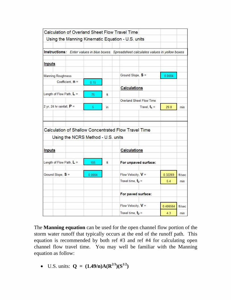
Solution: Substituting the slope into the U.S. equation for an unpaved surface gives: V = 16.135 (0.0004)0.5 = 0.3227 ft/sec. Then: t2 = L/(60V) = 105/(60*0.3227) = 5.4 min Example #5: Use the course spreadsheet to solve Example #3 and Example #4. Solution: The “Time of Concentration” tab in the course spreadsheet is set up to calculate the travel time for overland sheet flow with the Manning Kinematic Equation, the travel time for shallow concentrated flow using the NCRS method, and the travel time for channel flow using the Manning equation. The screenshot on the next page shows the solution to Example #5. The given information is shown entered into the blue cells. For Example #4, the inputs are: n = 0.15, L = 75 ft, P = 5 in, and S = 0.0004. The spreadsheet then calculates the overland sheet flow travel time in the yellow cell. The result is the same as the result shown above for Example #3:
t1 = 29.8 min For Example #4, the inputs are L = 105 ft and S = 0.0004. Entering these two values in the blue cells leads to values for V and t2 for an unpaved surface and for a paved surface. Since the surface described in Example #4 is unpaved, the answer for the shallow concentrated flow is the same as that calculated above:
t2 = 5.4 min
The Manning equation can be used for the open channel flow portion of the storm water runoff that typically occurs at the end of the runoff path. This equation is recommended by both ref #3 and ref #4 for calculating open channel flow travel time. You may well be familiar with the Manning equation as follow:
• U.S. units: Q = (1.49/n)A(R2/3)(S1/2)
• S.I. units: Q = (1.0/n)A(R2/3)(S1/2) Other equations (in addition to the Manning equation) that are used in calculating travel time for the open channel flow portion of the storm water runoff are:
• Velocity of flow = V = Q/A for either U.S. or S.I. units
• Travel time = t3 = L/(60V) for either U.S. or S.I. units The definitions and units for the parameters in these equations are:
• t3 is the open channel flow travel time (min for either U.S. or S.I. units)
• L is the length of the open channel flow path (ft – U.S. or m – S.I.) • V is the average open channel flow velocity (ft/sec – U.S. or m/s –
S.I.)
• Q is the flow rate in the open channel (cfs – U.S. or m3/s – S.I.)
• R is the hydraulic radius of the open channel flow (R = A/P with A and P as defined below) (ft – U.S. or m – S.I.)
• A is the cross-sectional area of the open channel flow (ft2 – U.S. or m2
– S.I.)
• P is the wetted perimeter of the open channel flow (ft – U.S. or m – S.I.)
• n = Manning roughness coefficient for the channel surface
(dimensionless) Example #6: What would be the travel time for the open channel flow portion of storm water runoff in a channel with bottom width = 2 ft; depth of flow = 1.2 ft; side slope = 3; Manning roughness = 0.022; channel bottom slope = 0.0003; and flow path length = 75 ft?
Solution: The solution proceeds by calculation of A, P, R, Q, V, and t3 as follows: For the trapezoidal channel: A = by + zy2 = 2*1.2 + 3*1.22 = 6.7 ft2 P = b + 2y(1 + z2)1/2 = 2 + 2*1.2(1 + 32)1/2 = 9.6 ft R = A/P = 6.7/9.6 ft = 0.70 ft Q = (1.49/n)A(R2/3)(S1/2) = (1.49/0.022)(6.7)(0.702/3)(0.00031/2) = 6.22 cfs V = Q/A = 6.22/6.7 ft/sec = 0.925 ft/sec Finally: t3 = L/(60V) = 75/(60*0.925) = 1.4 min Example #7: Use the course spreadsheet to solve Example #6. Solution: The travel time for channel flow can be calculated using the Manning equation in the worksheet at the “Time of Concentration” tab in the course spreadsheet. The screenshot on the next page shows the solution to Example #7.
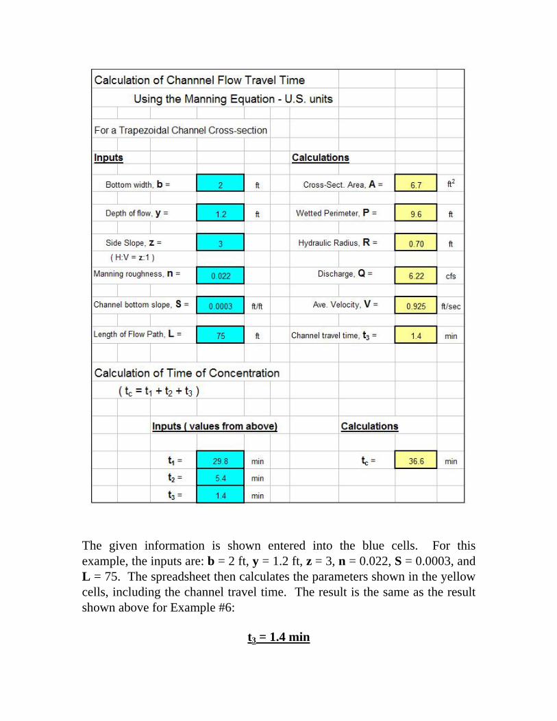
The given information is shown entered into the blue cells. For this example, the inputs are: b = 2 ft, y = 1.2 ft, z = 3, n = 0.022, S = 0.0003, and L = 75. The spreadsheet then calculates the parameters shown in the yellow cells, including the channel travel time. The result is the same as the result shown above for Example #6:
t3 = 1.4 min
Example #8: Calculate the time of concentration for a watershed that has the overland sheet flow travel time, concentrated shallow flow travel time, and channel flow travel time as calculated above in the previous several examples. Solution: The time of concentration, which is the total travel time from the periphery of the watershed to the outlet, is simply the sum of the overland sheet flow travel time (t1), the shallow concentrated flow travel time (t2), and the channel flow travel time (t3). Time of Concentration = 29.8 + 5.4 + 1.4 min = 36.6 min Note that the time of concentration is also calculated by the course spreadsheet, based on user input values for t1, t2, and t3. The result is the same value for time of concentration as shown in the screenshot on the previous page. 7. Design Rainfall Intensity The design rainfall intensity, i, for use in the Rational Method equation is the intensity of a constant intensity design storm with return period equal to a specified value for the purpose of the peak runoff rate being calculated, and duration equal to the time of concentration of the watershed. The return period to be used is typically specified by a state or local government agency. In order to determine the design storm intensity for known duration and return period, some type of intensity-duration-frequency (IDF) data for the location of interest is needed. In general, for a given return period, a shorter duration storm will be of greater intensity than a longer duration storm. IDF data is available from state agencies in many U.S. states. It may be in the form of graphs, tables, and/or equations. The figure below (adapted from Illinois State Water Survey Bulletin 70 (ref #5) shows an example IDF graph for northwest Illinios.
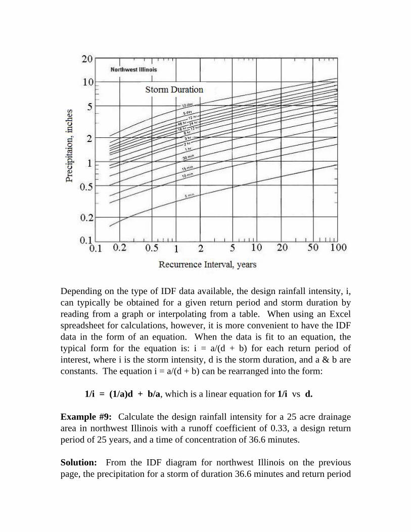
Depending on the type of IDF data available, the design rainfall intensity, i, can typically be obtained for a given return period and storm duration by reading from a graph or interpolating from a table. When using an Excel spreadsheet for calculations, however, it is more convenient to have the IDF data in the form of an equation. When the data is fit to an equation, the typical form for the equation is: i = a/(d + b) for each return period of interest, where i is the storm intensity, d is the storm duration, and a & b are constants. The equation i = a/(d + b) can be rearranged into the form:
1/i = (1/a)d + b/a, which is a linear equation for 1/i vs d. Example #9: Calculate the design rainfall intensity for a 25 acre drainage area in northwest Illinois with a runoff coefficient of 0.33, a design return period of 25 years, and a time of concentration of 36.6 minutes. Solution: From the IDF diagram for northwest Illinois on the previous page, the precipitation for a storm of duration 36.6 minutes and return period
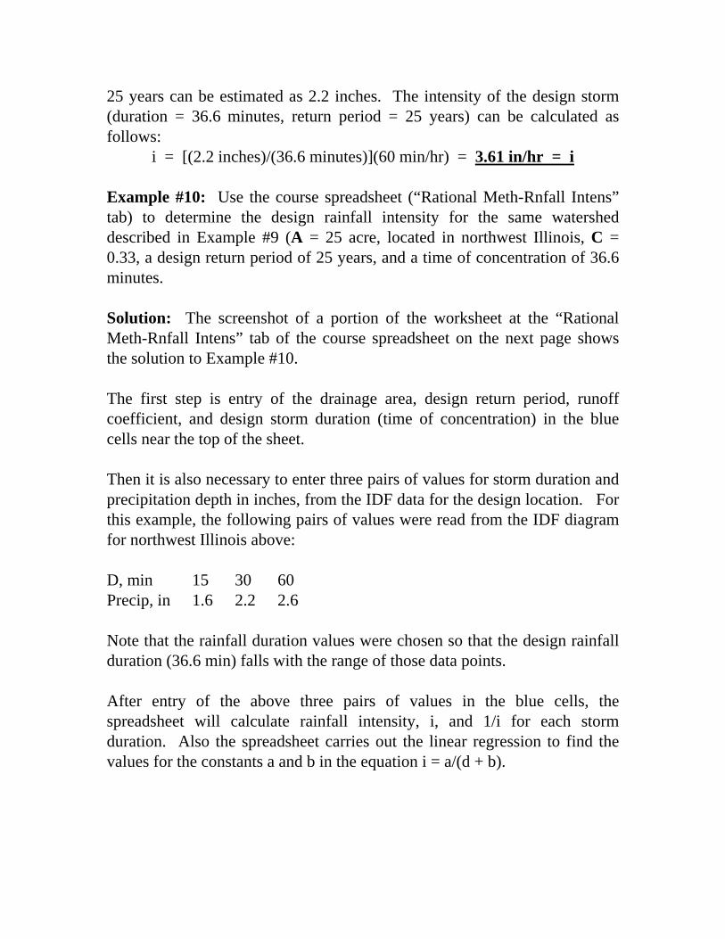
25 years can be estimated as 2.2 inches. The intensity of the design storm (duration = 36.6 minutes, return period = 25 years) can be calculated as follows:
i = [(2.2 inches)/(36.6 minutes)](60 min/hr) = 3.61 in/hr = i Example #10: Use the course spreadsheet (“Rational Meth-Rnfall Intens” tab) to determine the design rainfall intensity for the same watershed described in Example #9 (A = 25 acre, located in northwest Illinois, C = 0.33, a design return period of 25 years, and a time of concentration of 36.6 minutes. Solution: The screenshot of a portion of the worksheet at the “Rational Meth-Rnfall Intens” tab of the course spreadsheet on the next page shows the solution to Example #10. The first step is entry of the drainage area, design return period, runoff coefficient, and design storm duration (time of concentration) in the blue cells near the top of the sheet. Then it is also necessary to enter three pairs of values for storm duration and precipitation depth in inches, from the IDF data for the design location. For this example, the following pairs of values were read from the IDF diagram for northwest Illinois above: D, min 15 30 60 Precip, in 1.6 2.2 2.6 Note that the rainfall duration values were chosen so that the design rainfall duration (36.6 min) falls with the range of those data points. After entry of the above three pairs of values in the blue cells, the spreadsheet will calculate rainfall intensity, i, and 1/i for each storm duration. Also the spreadsheet carries out the linear regression to find the values for the constants a and b in the equation i = a/(d + b).
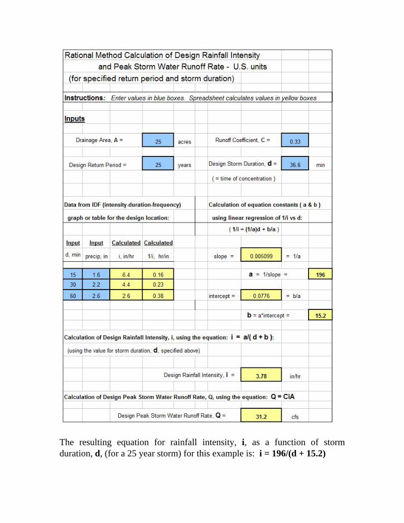
The resulting equation for rainfall intensity, i, as a function of storm duration, d, (for a 25 year storm) for this example is: i = 196/(d + 15.2)
The spreadsheet calculates the design rainfall intensity by substituting the specified design storm duration (36.6 min) into the equation, giving:
i = 3.78 in/hr Note that this is close to the value of i = 3.61 in/hr that was obtained in the Example #9 calculation. Both methods are limited by the accuracy to which the values can be read from the IDF diagram. 8. Peak Storm Water Runoff Rate Calculation The spreadsheet shown above with Example #10 will also calculate the peak storm water runoff rate, using the calculated design rainfall intensity, i, and specified watershed drainage area, A, and runoff coefficient, C, in the Rational Method equation: Q = CiA. The drainage area (A) is given as 25 acres and the runoff coefficient (C) is given as 0.33, so the design peak storm water runoff rate can be calculated from the Rational Method equation; Q = CiA. Thus: Q = (0.33)(3.78)(25) = 31.2 cfs = Q Using the design rainfall intensity from Example #9 (i = 3.61 in/hr): Q = (0.33)(3.61)(25) = 29.7 cfs = Q 9. The Steel Equation for Design Rainfall Intensity The Steel equation is an alternative for calculating design rainfall intensity for a location where good IDF data is not available. The Steel equation is:
i = a/(d + b) Values for the constants a and b for seven regions of the United States for return periods of 2, 5, 10, 25, 50, and 100 years are given in the table below. The seven U.S. regions are shown on the following map.
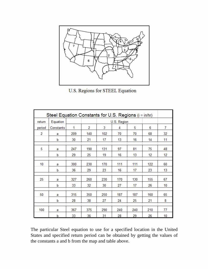
The particular Steel equation to use for a specified location in the United States and specified return period can be obtained by getting the values of the constants a and b from the map and table above.
Example #11: Use the Steel equation to find the design rainfall intensity and peak storm water runoff rate for a 25 acre drainage area in northwest Illinois with a runoff coefficient of 0.33, a design return period of 25 years, and a time of concentration of 36.6 minutes. Solution: The map above shows northwest Illinois to be in region 3 of the United States. The table shows the following values of the constants a and b for a 25 year return period in region 3: a = 230, b = 30. The equation for rainfall intensity as a function of storm duration is thus:
i = 230/(d + 30) Substituting d = 36.6 minutes gives:
i = 230/(36.6 + 30) = 3.45 in/hr The peak storm water runoff rate can now be calculated using the Rational Method equation:
Q = CiA = (0.33)(3.45)(25) = 28.5 cfs Example #12: Use the course spreadsheet (“Steel Equation” tab) to solve Example #11. Solution: The screenshot (from the “Steel Equation” tab) on the next page shows the solution to this Example. The drainage area, design return period, runoff coefficient, and design storm duration (time of concentration) values are entered into the blue cells near the top of the spreadsheet. Then the Steel equation constants need to be identified using the map and table. Those constants (a and b) are then entered into the appropriate blue cells. The spreadsheet then calculates the design storm intensity and the design peak storm water runoff rate. The results are: i = 3.45 in/hr and Q = 28.5 cfs
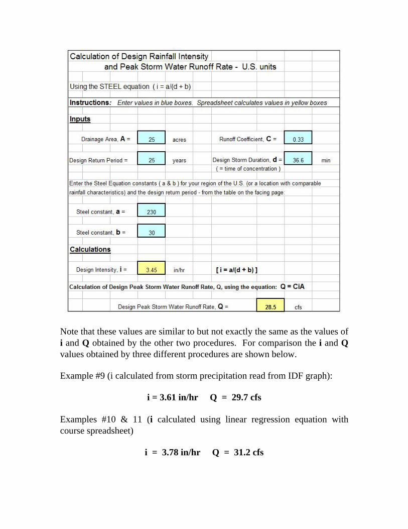
Note that these values are similar to but not exactly the same as the values of i and Q obtained by the other two procedures. For comparison the i and Q values obtained by three different procedures are shown below. Example #9 (i calculated from storm precipitation read from IDF graph):
i = 3.61 in/hr Q = 29.7 cfs Examples #10 & 11 (i calculated using linear regression equation with course spreadsheet)
i = 3.78 in/hr Q = 31.2 cfs
Example #12 (i calculated using the Steel equation):
i = 3.45 in/hr Q = 28.5 cfs 10. Summary The Rational Method equation, Q = CiA, is widely used to calculate peak storm water runoff rate for a variety of storm water management applications. As described in this course, Excel spreadsheets can be useful for calculation of the watershed time of concentration (used as duration of design storm); to prepare an equation for design storm intensity as a function of storm duration by linear regression, and to calculate the peak storm water runoff rate. Calculation of the design storm intensity with the Steel equation can also be conveniently done with a spreadsheet. Numerous example calculations and solutions using the spreadsheet included with the course were presented and discussed. 11. References 1. McCuen, Richard H., Hydrologic Analysis and Design, 2nd Ed, Upper Saddle River, NJ, 1998. 2. Steel, E.W. & McGhee, T.J., Water Supply and Sewerage, 5th Ed., New York, McGraw-Hill Book Company, 1979 3. Knox County Tennessee, Stormwater Management Manual, section on the Rational Method 4. U.S. Soil Conservation Service, Technical Note - Hydrology No N4,June 17, 1986. 5. Iowa Stormwater Management Manual, Section on Time of Concentration. 6. Illinois State Water Survey, Bulletin 70.