Embed Size (px)
Citation preview
Troubleshooting Guide CTTG #145
rb Trip Code Resolver Troubleshooting
This guide pertains to drives using Resolver Feedback
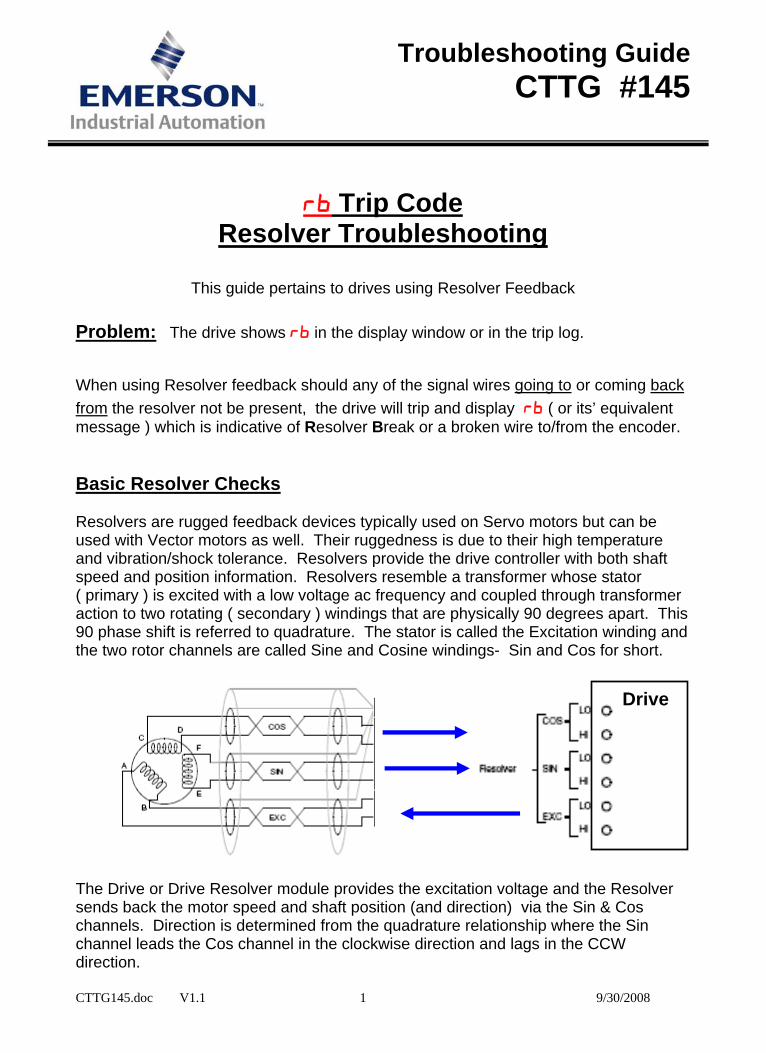
Problem: The drive shows rb in the display window or in the trip log. When using Resolver feedback should any of the signal wires going to or coming back from the resolver not be present, the drive will trip and display rb ( or its’ equivalent message ) which is indicative of Resolver Break or a broken wire to/from the encoder. Basic Resolver Checks Resolvers are rugged feedback devices typically used on Servo motors but can be used with Vector motors as well. Their ruggedness is due to their high temperature and vibration/shock tolerance. Resolvers provide the drive controller with both shaft speed and position information. Resolvers resemble a transformer whose stator ( primary ) is excited with a low voltage ac frequency and coupled through transformer action to two rotating ( secondary ) windings that are physically 90 degrees apart. This 90 phase shift is referred to quadrature. The stator is called the Excitation winding and the two rotor channels are called Sine and Cosine windings- Sin and Cos for short.
CTTG145.doc V1.1 1 9/30/2008
Drive The Drive or Drive Resolver module provides the excitation voltage and the Resolver sends back the motor speed and shaft position (and direction) via the Sin & Cos channels. Direction is determined from the quadrature relationship where the Sin channel leads the Cos channel in the clockwise direction and lags in the CCW direction.
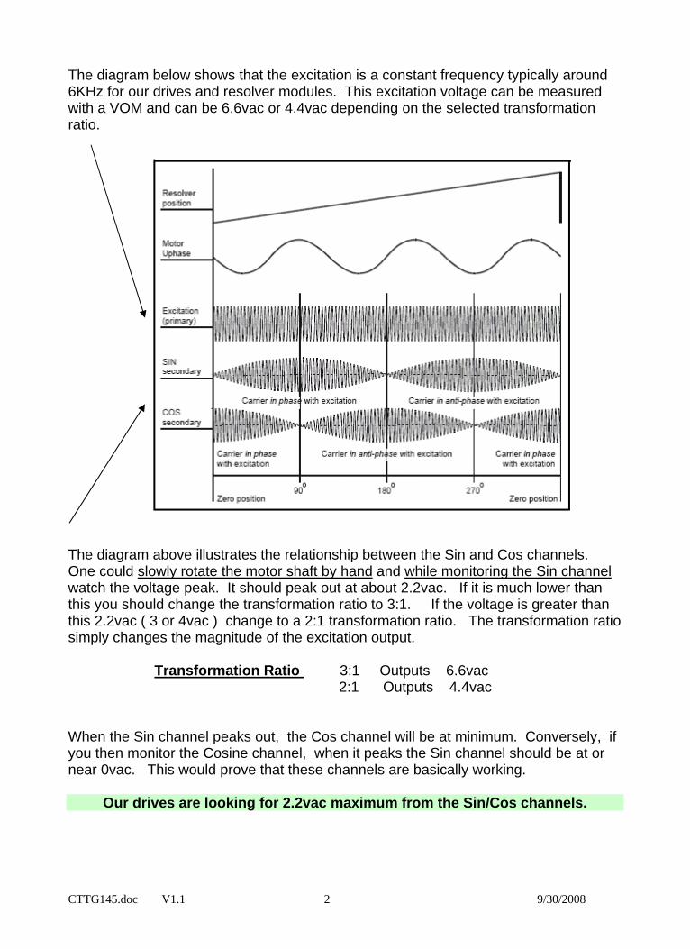
The diagram below shows that the excitation is a constant frequency typically around 6KHz for our drives and resolver modules. This excitation voltage can be measured with a VOM and can be 6.6vac or 4.4vac depending on the selected transformation ratio.
CTTG145.doc V1.1 2 9/30/2008
The diagram above illustrates the relationship between the Sin and Cos channels. One could slowly rotate the motor shaft by hand and while monitoring the Sin channel watch the voltage peak. It should peak out at about 2.2vac. If it is much lower than this you should change the transformation ratio to 3:1. If the voltage is greater than this 2.2vac ( 3 or 4vac ) change to a 2:1 transformation ratio. The transformation ratio simply changes the magnitude of the excitation output. Transformation Ratio 3:1 Outputs 6.6vac 2:1 Outputs 4.4vac When the Sin channel peaks out, the Cos channel will be at minimum. Conversely, if you then monitor the Cosine channel, when it peaks the Sin channel should be at or near 0vac. This would prove that these channels are basically working.
Our drives are looking for 2.2vac maximum from the Sin/Cos channels.
CTTG145.doc V1.1 3 9/30/2008
BASIC RESOLVER TROUBLESHOOTING QUESTIONS Is the problem with the drive or the Resolver ? Does the drive send out an excitation voltage of 4.4vac or 6.6vac ? If not you may need to remove the excitation wires from the drive and re-measure. I don’t know which wires are which on the resolver ? You need to determine which is the stator/excitation winding and which are the rotor windings. The rotor windings will have approximately the same ohmic resistance and the excitation winding will be the different than the other two ( typically higher ohms ). If you measure either a short or open on a winding at the drive end, the problem could easily been in the Resolver cabling. You will need to go to the motor end of the cable and re-measure the Resolver connections at that end- you will need to remove wires to eliminate problems within the cable from influencing your readings- HINT: Photograph or make a drawing of your wires before removal ! How do I determine if the Resolver is working ? Does the drive send out an excitation voltage of 4.4vac or 6.6vac ? If yes, you need to rotate the motor slowly while measuring the Sin Hi and Sin Lo channel. It should peak around 2.2vac. The Cos Hi and Cos Lo channel should measure about 0vac. Continue to monitor the Cos Hi and Cos Lo channel and rotate the motor slowly. The Cos Hi and Cos Lo channel should peak around 2.2vac and the Sin Hi and Lo should measure about 0vac. This would tend to indicate the Resolver and associated wiring is fine ( at least at low speeds ). There is excitation voltage but nothing coming back on the Sin or Cos channels, What could be wrong ? The Resolver may be broke but before jumping to that conclusion measure the resistance of each winding ( with power off of course ! ) . The rotor windings will have approximately the same ohmic resistance and the excitation winding will be the different than the other two ( typically higher ohms ). Re-apply power, verify excitation voltage at the Resolver excitation winding. Remove Sin/Cos wires from the drive and slowly rotate motor looking for 0-2vac action. If the Sin/Cos channels work but not after you attach to the drive or drive module, the drive or drive module may be defective as the signal appears to be loaded down. The Sin and Cos channels only send back about 1.5vac ? Select a 3:1 Transformation Ratio ( some drives only accommodate 3:1 ) The Sin and Cos channels send back about 3.3vac ? Select a 2:1 Transformation Ratio ( some drives do not have this option )
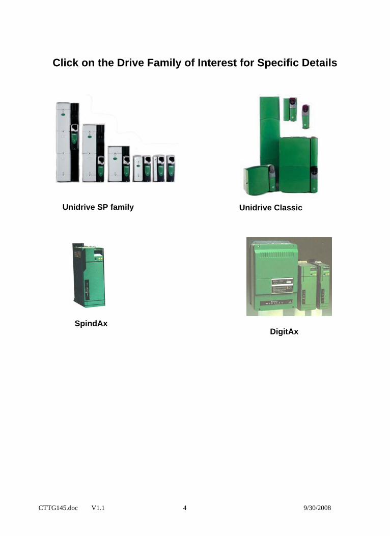
Click on the Drive Family of Interest for Specific Details
Unidrive SP family Unidrive Classic
SpindAx DigitAx
CTTG145.doc V1.1 4 9/30/2008
Unidrive SP
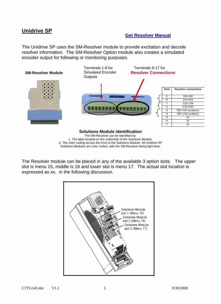
Get Resolver Manual The Unidrive SP uses the SM-Resolver module to provide excitation and decode resolver information. The SM-Resolver Option module also creates a simulated encoder output for following or monitoring purposes.
CTTG145.doc V1.1 5 9/30/2008
Terminals 1-8 for Simulated Encoder Outputs
Terminals 9-17 for Resolver Connections
SM-Resolver Module
Solutions Module identification The SM-Resolver can be identified by:
1. The label located on the underside of the Solutions Module. 2. The color coding across the front of the Solutions Module. All Unidrive SP Solutions Modules are color coded, with the SM-Resolver being light blue.
The Resolver module can be placed in any of the available 3 option slots. The upper slot is menu 15, middle is 16 and lower slot is menu 17. The actual slot location is expressed as xx. in the following discussion.
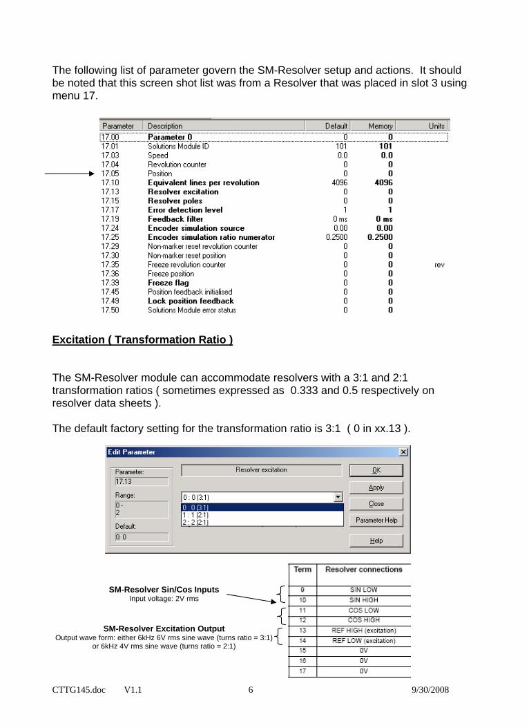
The following list of parameter govern the SM-Resolver setup and actions. It should be noted that this screen shot list was from a Resolver that was placed in slot 3 using menu 17. Excitation ( Transformation Ratio ) The SM-Resolver module can accommodate resolvers with a 3:1 and 2:1 transformation ratios ( sometimes expressed as 0.333 and 0.5 respectively on resolver data sheets ). The default factory setting for the transformation ratio is 3:1 ( 0 in xx.13 ).
SM-Resolver Sin/Cos Inputs
CTTG145.doc V1.1 6 9/30/2008
Input voltage: 2V rms
SM-Resolver Excitation Output Output wave form: either 6kHz 6V rms sine wave (turns ratio = 3:1)
or 6kHz 4V rms sine wave (turns ratio = 2:1)
CTTG145.doc V1.1 7 9/30/2008
Testing Resolver (Unidrive SP) With drive disabled ( display indicating inh ), go to parameter # xx.05 and monitor while rotating the motor or resolver slowly clockwise. Parameter #xx.05 should count up to 65,536 and roll over to 0 in one revolution of the resolver/motor shaft. Likewise, CCW rotation should make this register count down. This action is a pre-requisite before performing and obtaining a successful phasing test which is part of the auto tune procedure. If this does not occur consult ( click the link below):
BASIC RESOLVER TROUBLESHOOTING
If the Unidrive SP indicates Enc2 Trip, ensure that parameter #3.40 is set to 0 to disable the drives basic Encoder Feedback loss trip ( assuming there is nothing plugged into the drives on-board Encoder port )
For Slot SLx. Fault Codes consult ( click the link below):
Option Module Trip Codes
Refer to Module code 101 in #xx.01
Unidrive Classic
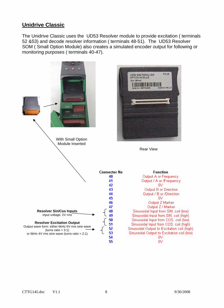
The Unidrive Classic uses the UD53 Resolver module to provide excitation ( terminals 52 &53) and decode resolver information ( terminals 48-51). The UD53 Resolver SOM ( Small Option Module) also creates a simulated encoder output for following or monitoring purposes ( terminals 40-47).
CTTG145.doc V1.1 8 9/30/2008
With Small Option Module Inserted
Rear View
Resolver Sin/Cos Inputs Input voltage: 2V rms
Resolver Excitation Output
Output wave form: either 6kHz 6V rms sine wave (turns ratio = 3:1)
or 6kHz 4V rms sine wave (turns ratio = 2:1)
CTTG145.doc V1.1 9 9/30/2008
Unidrive Classic Excitation ( Transformation Ratio ) The UD53 Resolver module can accommodate resolvers with a 3:1 and 2:1transformation ratios ( sometimes expressed as 0.333 and 0.5 respectively on resolver data sheets ). The default factory setting for the transformation ratio is 3:1 ( 0 in 16.10 ). Parameter 16.10 Resolver Ratio Select Default setting: 0 Note : This parameter is only available when the software version is 3.01.07 or higher ( see parameter #11.29 for software version number ) Note : Issue 2.00 hardware must be used for this parameter to operate correctly. With earlier versions a resolver with a 3:1 transformation ratio must be used. With the default setting the option module operates with a standard CT dynamics resolver which has a turns ratio of 3:1 (excitation winding:output windings). If this parameter is set to one the option module operates with resolvers which have a turns ratio of 2:1 (excitation winding:output windings).
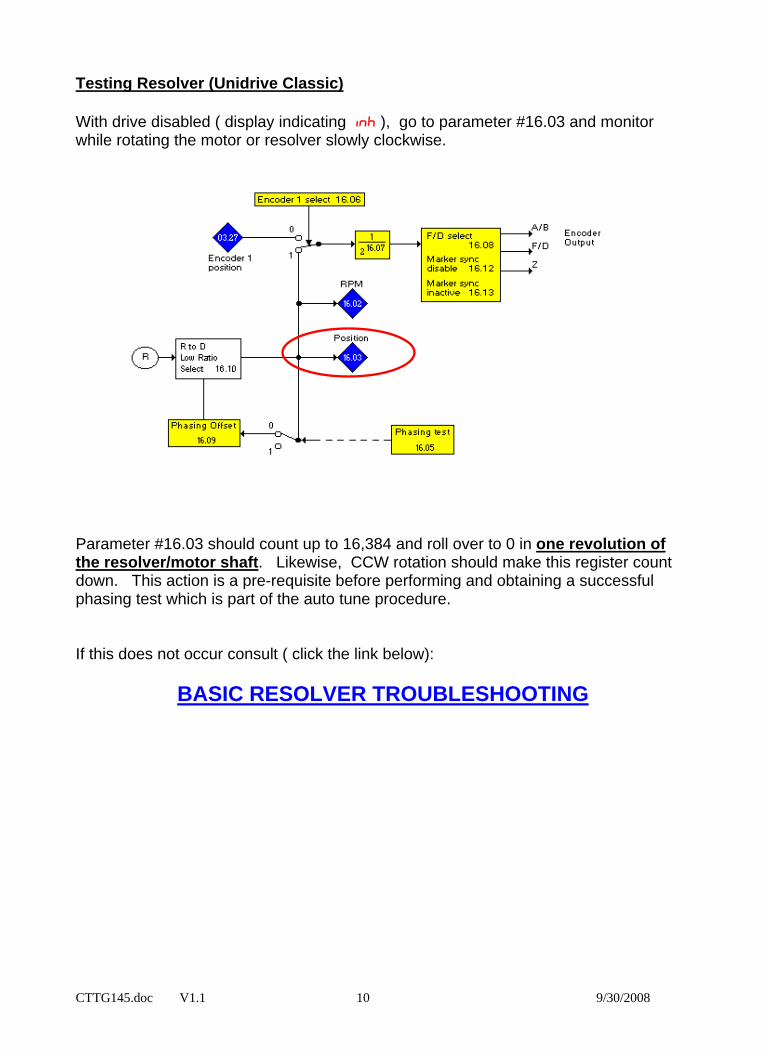
Testing Resolver (Unidrive Classic) With drive disabled ( display indicating inh ), go to parameter #16.03 and monitor while rotating the motor or resolver slowly clockwise.
CTTG145.doc V1.1 10 9/30/2008
Parameter #16.03 should count up to 16,384 and roll over to 0 in one revolution of the resolver/motor shaft. Likewise, CCW rotation should make this register count down. This action is a pre-requisite before performing and obtaining a successful phasing test which is part of the auto tune procedure. If this does not occur consult ( click the link below):
BASIC RESOLVER TROUBLESHOOTING
DigitAx Excitation ( Transformation Ratio )
CTTG145.doc V1.1 11 9/30/2008
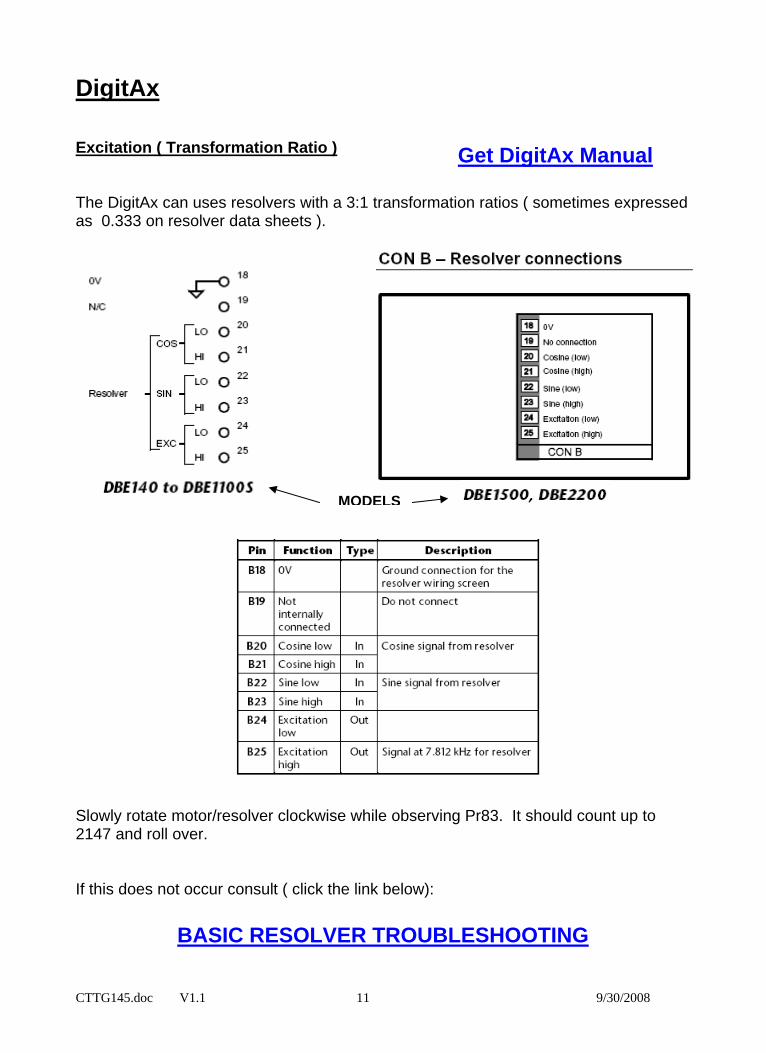
The DigitAx can uses resolvers with a 3:1 transformation ratios ( sometimes expressed as 0.333 on resolver data sheets ).
Get DigitAx Manual
MODELS Slowly rotate motor/resolver clockwise while observing Pr83. It should count up to 2147 and roll over. If this does not occur consult ( click the link below):
BASIC RESOLVER TROUBLESHOOTING
SpindAx
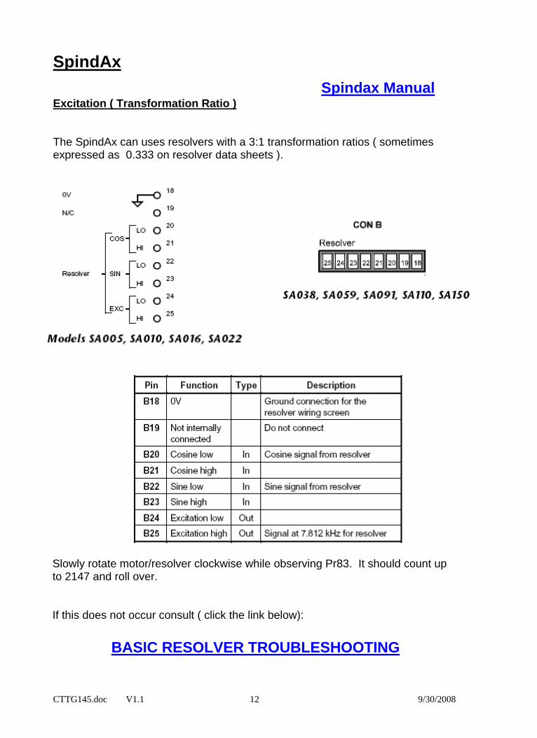
Spindax Manual Excitation ( Transformation Ratio ) The SpindAx can uses resolvers with a 3:1 transformation ratios ( sometimes expressed as 0.333 on resolver data sheets ).
Slowly rotate motor/resolver clockwise while observing Pr83. It should count up to 2147 and roll over. If this does not occur consult ( click the link below):
BASIC RESOLVER TROUBLESHOOTING
CTTG145.doc V1.1 12 9/30/2008

CTTG145.doc V1.1 13 9/30/2008
Americas Service Center 1-800-367-8067 Questions ?? Ask the Author: Author: Ray McGranor e-mail : [email protected] (716)-774-0093