Embed Size (px)
Citation preview
©
Reactor Loading Procedure CTR
1st Haldor Topsoe Workshop
REPSOL. TECHNOLOGY CENTRE. 17th Mar 2016
©
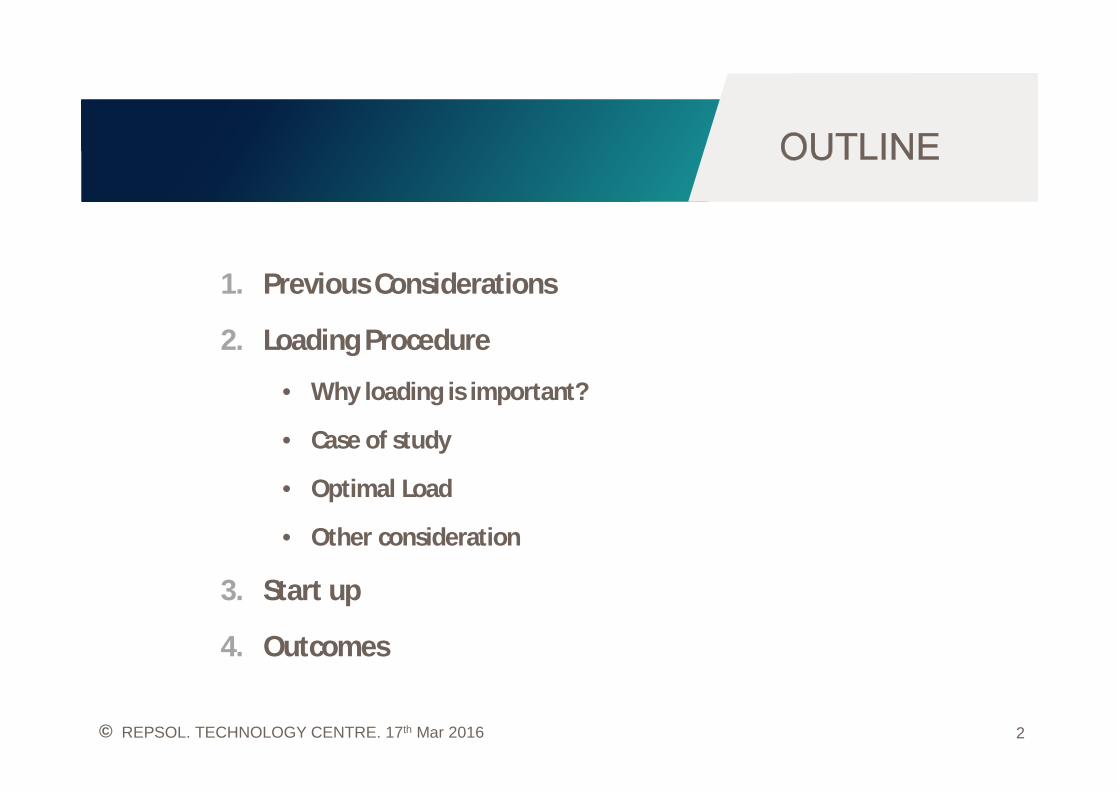
1. Previous Considerations
2. Loading Procedure
• Why loading is important?
• Case of study
• Optimal Load
• Other consideration
3. Start up
4. Outcomes
2REPSOL. TECHNOLOGY CENTRE. 17th Mar 2016
©
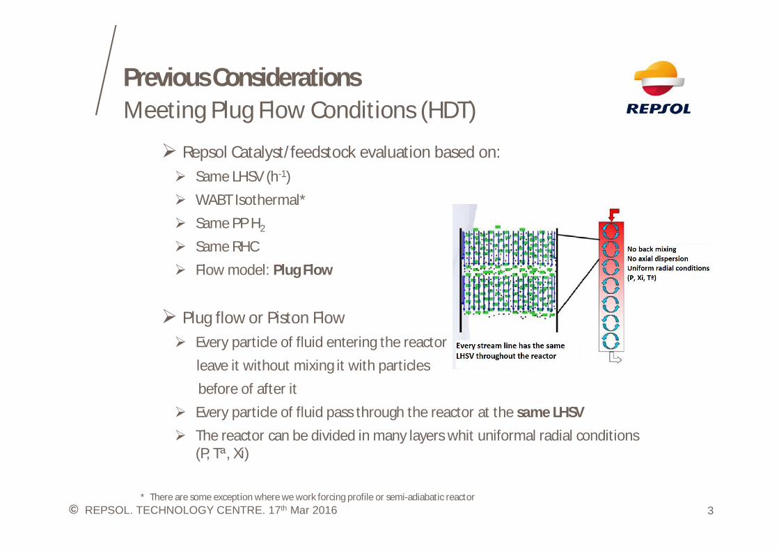
Previous Considerations
Ø Repsol Catalyst/feedstock evaluation based on:Ø Same LHSV (h-1)Ø WABT Isothermal*Ø Same PP H2
Ø Same RHCØ Flow model: Plug Flow
Ø Plug flow or Piston FlowØ Every particle of fluid entering the reactor
leave it without mixing it with particlesbefore of after it
Ø Every particle of fluid pass through the reactor at the same LHSVØ The reactor can be divided in many layers whit uniformal radial conditions
(P, Tª, Xi)
* There are some exception where we work forcing profile or semi-adiabatic reactor
Meeting Plug Flow Conditions (HDT)
3REPSOL. TECHNOLOGY CENTRE. 17th Mar 2016

©
Previous Considerations
Ø Wall Effect: liquid velocity increase or decrease in the proximity of reactorwall producing desviation from Plug Flow.
D/Dbed > 25Ø Bed Lenght Effect: reduce the bed lenght while keeping the LHSV constant
mean lower fluid flowrate and lower superficial velocity.
Ø Complete Irrigation: every particle of catalyst must contribute to theglobal conversion
Ø Particle diameter:Ø Catalys crushed: lead to overestimate results due to mass transfer limitations
metal contamination etcØ Inert dilution: hydrodinamic is governed by
inert dilution while keeping activity of catalyst
Meeting Plug Flow Conditions (HDT)
4REPSOL. TECHNOLOGY CENTRE. 17th Mar 2016
©
Previous ConsiderationsMeeting Plug Flow Conditions (HDT)
5REPSOL. TECHNOLOGY CENTRE. 17th Mar 2016
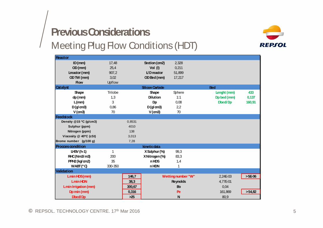
ReactorID (mm) 17,48 Section (cm2) 2,328OD (mm) 25,4 Vol (l) 0,211
Lreactor (mm) 907,2 L/D reactor 51,899OD TW (mm) 3,02 OD Bed (mm) 17,217
Flow UpflowCatalyst Silicon Carbide Bed
Shape Trilobe Shape Sphere Lenght (mm) 433dp (mm) 1,3 Dilution 1:1 Dp bed (mm) 0,137L (mm) 3 Dp 0,08 Dbed/Dp 160,91
D (g/cm3) 0,86 D (g/cm3) 2,2V (cm3) 70 V (cm3) 70
FeedstockDensity @15 ºC (g/cm3) 0,8531
Sulphur (ppm) 4010Nitrogen (ppm) 138
Viscosity @ 40ºC (cSt) 3,013Brome number (g/100 g) 7,28
Procces condition kinetic dataLHSV (h-1) 1 X Sulphur (%) 99,3
RHC (Nm3/m3) 200 X Nitrogen (%) 83,3PPH2 (kg/cm2) 35 n HDS 1,4
WABT (ºC) 330-350 n HDN 1Validation
L min HDS (mm) 146,7 Wetting number "W" 2,24E-03 > 5E-06L min HDN 38,3 Reynolds 4,77E-01
L min Irrigation (mm) 300,67 Bo 0,04Dp min (mm) 0,316 Pe 161,869 > 54,82
Dbed/Dp >25 N 80,9
©
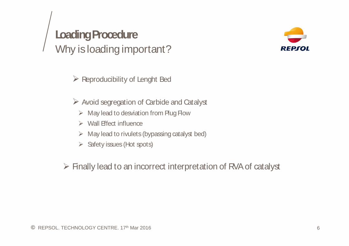
Loading ProcedureWhy is loading important?
6REPSOL. TECHNOLOGY CENTRE. 17th Mar 2016
Ø Reproducibility of Lenght Bed
Ø Avoid segregation of Carbide and CatalystØ May lead to desviation from Plug FlowØ Wall Effect influenceØ May lead to rivulets (bypassing catalyst bed)Ø Safety issues (Hot spots)
Ø Finally lead to an incorrect interpretation of RVA of catalyst
©
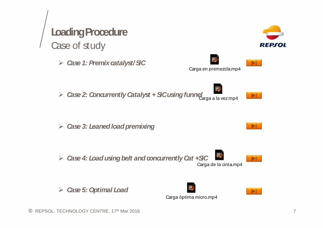
Loading ProcedureCase of study
7REPSOL. TECHNOLOGY CENTRE. 17th Mar 2016
Ø Case 1: Premix catalyst/SiC
Ø Case 2: Concurrently Catalyst + SiC using funnel
Ø Case 3: Leaned load premixing
Ø Case 4: Load using belt and concurrently Cat +SiC
Ø Case 5: Optimal Load
Carga en premezcla.mp4
Carga a la vez.mp4
Carga de la cinta.mp4
Carga óptima micro.mp4
©
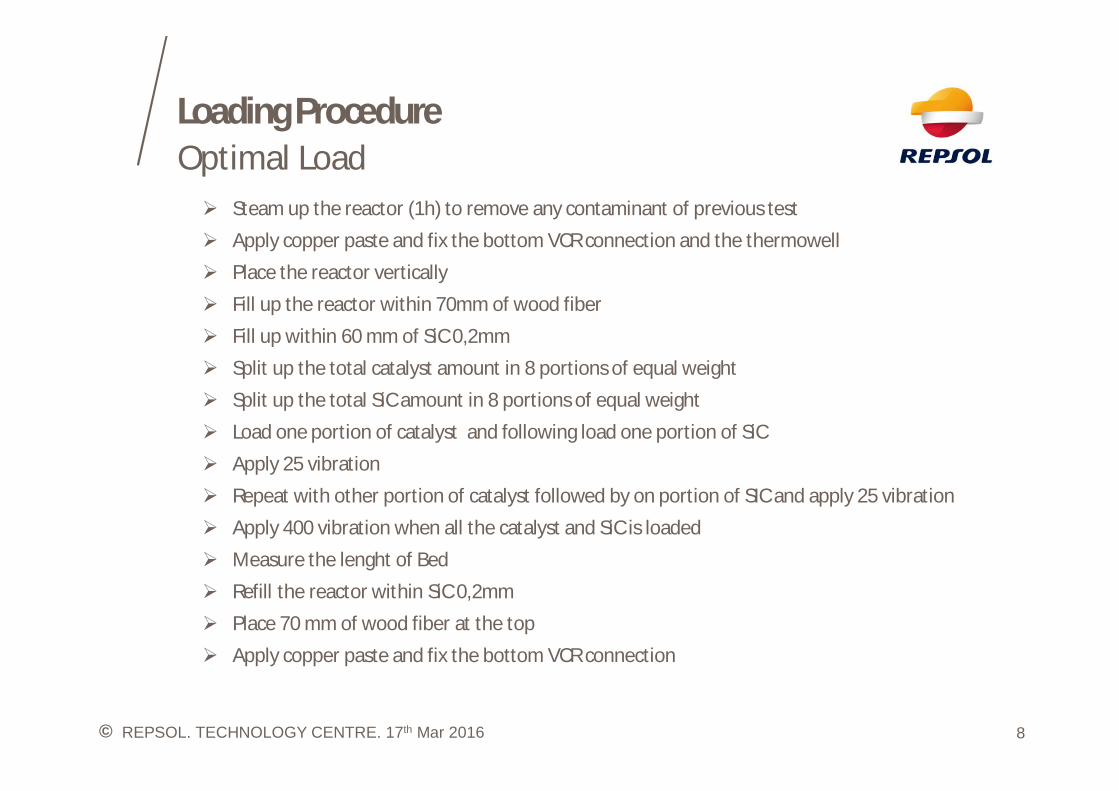
Loading ProcedureOptimal Load
8REPSOL. TECHNOLOGY CENTRE. 17th Mar 2016
Ø Steam up the reactor (1h) to remove any contaminant of previous testØ Apply copper paste and fix the bottom VCR connection and the thermowellØ Place the reactor verticallyØ Fill up the reactor within 70mm of wood fiberØ Fill up within 60 mm of SiC 0,2mmØ Split up the total catalyst amount in 8 portions of equal weightØ Split up the total SiC amount in 8 portions of equal weightØ Load one portion of catalyst and following load one portion of SiCØ Apply 25 vibrationØ Repeat with other portion of catalyst followed by on portion of SIC and apply 25 vibrationØ Apply 400 vibration when all the catalyst and SiC is loadedØ Measure the lenght of BedØ Refill the reactor within SiC 0,2mmØ Place 70 mm of wood fiber at the topØ Apply copper paste and fix the bottom VCR connection
©
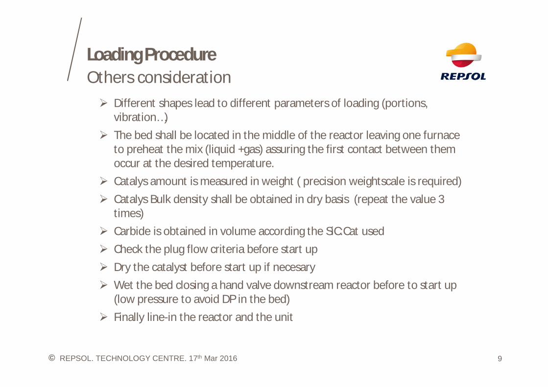
Loading ProcedureOthers consideration
9REPSOL. TECHNOLOGY CENTRE. 17th Mar 2016
Ø Different shapes lead to different parameters of loading (portions,vibration…)
Ø The bed shall be located in the middle of the reactor leaving one furnaceto preheat the mix (liquid +gas) assuring the first contact between themoccur at the desired temperature.
Ø Catalys amount is measured in weight ( precision weightscale is required)Ø Catalys Bulk density shall be obtained in dry basis (repeat the value 3
times)Ø Carbide is obtained in volume according the SiC:Cat usedØ Check the plug flow criteria before start upØ Dry the catalyst before start up if necesaryØ Wet the bed closing a hand valve downstream reactor before to start up
(low pressure to avoid DP in the bed)Ø Finally line-in the reactor and the unit

©
Start upSulphide and stabilize step
10REPSOL. TECHNOLOGY CENTRE. 17th Mar 2016
Ø Follow the vendor procedure to presulphide the CatalystØ Stabilize the Catalyst with SR destillate (mesure de Brome Number to assure no
olephines presente in the feed)Ø Incresase the temperature by ramp (50º C/h) over 320ºC (5-10ºC/h) to avoid peak
of temperature at the early hoursØ Stabilize catalyst for minimum 72h to and follow the sulphur downstream the
reactorØ If any unexpected shutdown occur during presulphide or stabilization step,
shutdown the unit and load fresh catalystØ If any unexpected shutdown occur during test repeat a previous temperature and
decide if go on or load fresh catalystØ Configured InterlocksØ Safety reasonØ Protect catalyst if shutdown occur during unattended time
©
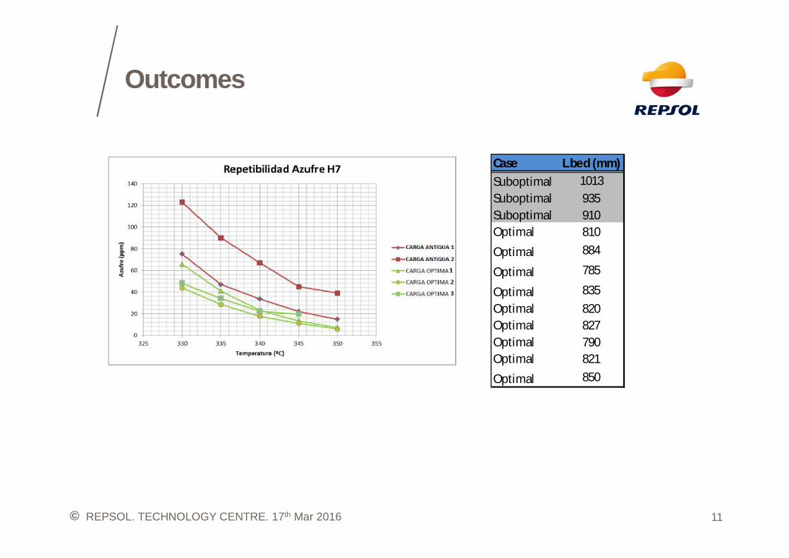
Outcomes
11REPSOL. TECHNOLOGY CENTRE. 17th Mar 2016
Case L bed (mm)Suboptimal 1013Suboptimal 935Suboptimal 910Optimal 810
Optimal 884
Optimal 785
Optimal 835Optimal 820Optimal 827Optimal 790Optimal 821
Optimal 850

©
THANK YOU
© REPSOL. TECHNOLOGY CENTRE. 17th Mar 2016
©
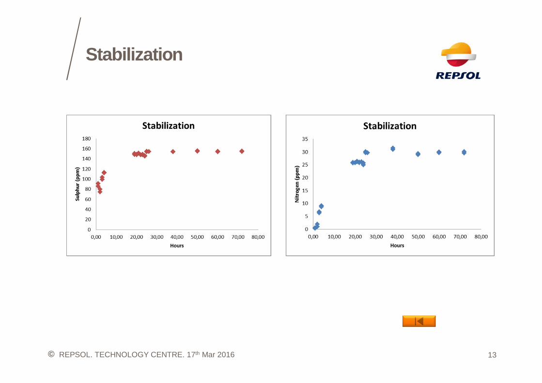
Stabilization
13REPSOL. TECHNOLOGY CENTRE. 17th Mar 2016
© REPSOL. TECHNOLOGY CENTRE. 17th Mar 2016
2 4 6 8 10
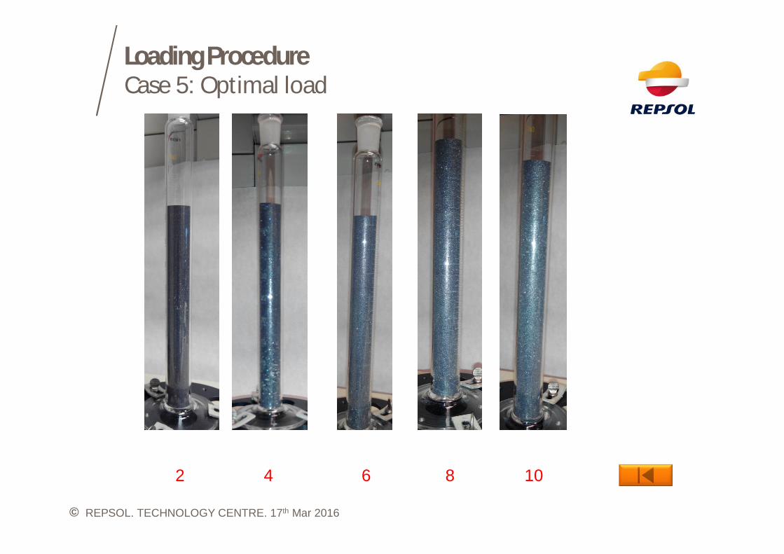
Loading ProcedureCase 5: Optimal load
©
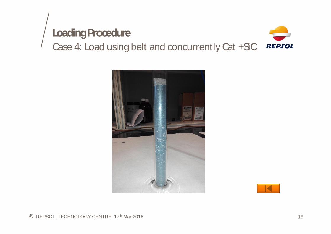
Loading ProcedureCase 4: Load using belt and concurrently Cat +SiC
15REPSOL. TECHNOLOGY CENTRE. 17th Mar 2016
©
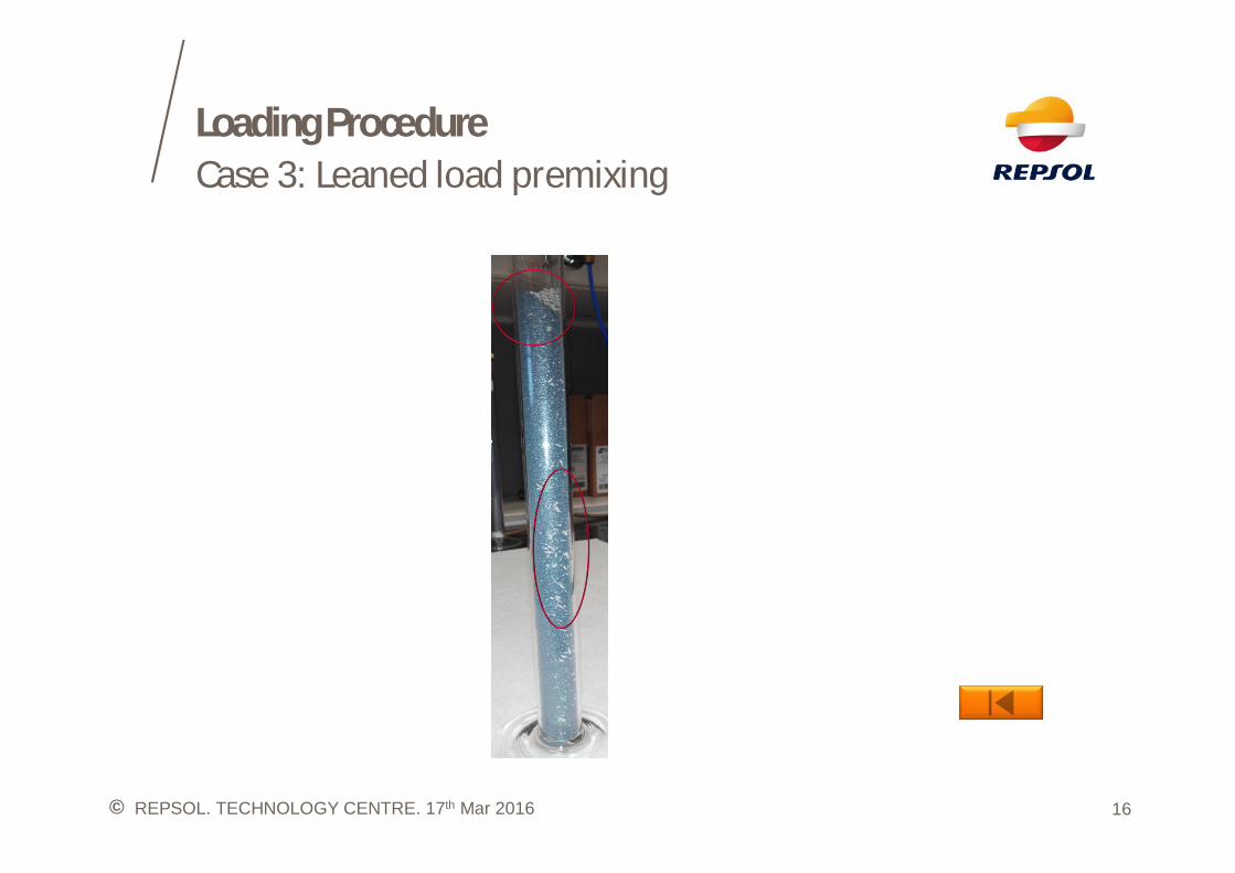
Loading ProcedureCase 3: Leaned load premixing
16REPSOL. TECHNOLOGY CENTRE. 17th Mar 2016
©
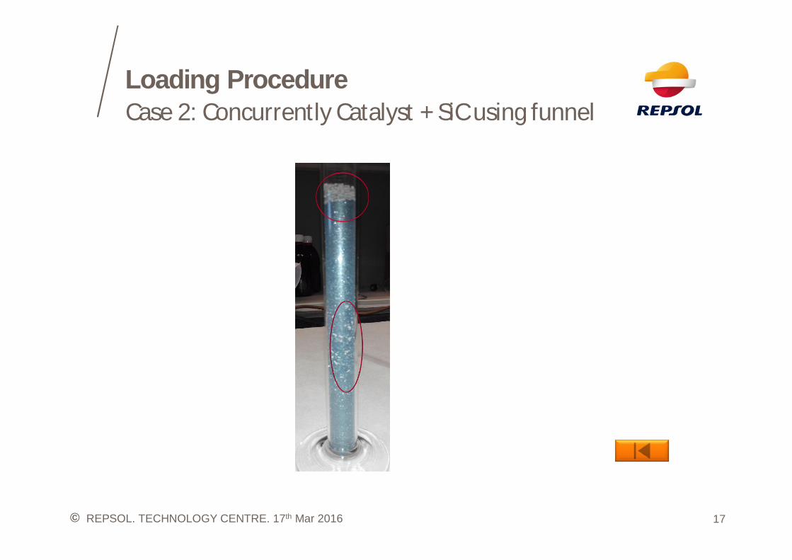
Loading ProcedureCase 2: Concurrently Catalyst + SiC using funnel
17REPSOL. TECHNOLOGY CENTRE. 17th Mar 2016
©
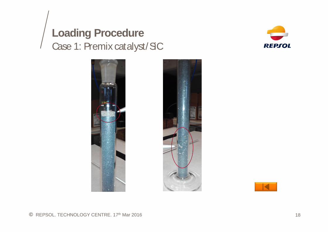
Loading ProcedureCase 1: Premix catalyst/SiC
18REPSOL. TECHNOLOGY CENTRE. 17th Mar 2016