Embed Size (px)
Citation preview
Real-Time EMG driven Lower Limb ActuatedOrthosis for Assistance As Needed Movement
StrategyWalid Hassani, Samer Mohammed, Yacine Amirat
LISSI Lab, University Paris Est Creteil (UPEC)Vitry Sur Seine, 94400, France
Email: {walid.hassani,samer.mohammed,amirat}@u-pec.fr
Abstract—This paper presents a new approach to control awearable knee joint exoskeleton driven through the wearer’sintention. A realistic bio-inspired musculoskeletal knee jointmodel is used to control the exoskeleton. This model takes intoaccount changes in muscle length and joint moment arms aswell as the dynamics of muscle activation and muscle contractionduring lower limb movements. Identification of the model param-eters is done through an unconstrained optimization problemformulation. A control law strategy based on the principle ofassistance as needed is proposed. This approach guaranteesasymptotic stability of the knee joint orthosis and adaptation tohuman-orthosis interaction. Moreover, the proposed control lawis robust with respect to external disturbances. Experimentalvalidations are conducted online on a healthy subject duringflexion and extenion of their knee joint. The proposed controlstrategy has shown satisfactory performances in terms of trackingtrajectory and adaptation to human tasks completion.
I. I NTRODUCTION
Exoskeletons are mainly used in assisting and rehabilitatingdependent people as well as in human power augmentation.They have known a huge expansion in the last decade asthey are continually attracting the scientific and the medicalcommunity due to the continuous increasing rate of dependentpeople [16], [17]. Research in this field has started in thesixties and has tended to assist depending people by couplingthe exoskeleton with their limbs in the aim of allowing thewearer to regain natural movements [8]. The key issue whendealing with wearable exoskeletons concerns the interactionbetween wearer and the exoskeleton from a physical or acognitive point of view and ideally from both [19]. The mostdeveloped exoskeleton research projets are based on physicalinteraction, through force interfaces, whether by imposingpredefined movements [28, 13], or by using forces sensorsbetween the exoskeleton and the wearer and/or the inversedynamics of the wearer body [8, 20, 5, 6]. One of the majordrawbacks of this physical interaction mode is the poornessreactivity of the exoskeleton caused by the time delay betweenthe wearer’s intention estimation and the control input appliedto the exoskeleton [4]. This can be very tiring particularlyfordependent people. Moreover, this interaction mode requiresthe use of an accurate inverse dynamics model, that is verysensitive to the human anthropomorphic parameters.
An alternative approach is the cognitive human-exoskeletoninteraction that allows a closed loop interaction schema ac-
cording to the three following steps: the first one concernsthe reasoning and planning tasks (brain activities), the secondone is related to muscle activity measurements through theElectromyography (EMG) and the third one concerns thegeneration of the assisting exoskeleton movements [19]. Thecognitive interaction mode is biologically inspired and isdone through neural excitation of given skeletal muscles. Thisapproach takes full advantage of the human natural controlmechanisms [19]. However, such interaction mode is a com-plex mechanism because it requires; (i) an efficient processingof the EMG signals that are in general noisy, (ii) an accurateestimation of the wearer’s intention, i.e, the necessary torqueto achieve a given desired movement. This estimation needs aprecise and realistic musculoskeletal modeling of the assistedjoint, (iii) a balancing strategy between the wearer’s contribu-tion and the exoskeleton’s one such that the exoskeleton willbe able to compensate the deficiency in the human generatedtorque. To the authors’ best knowledge, only few workshave addressed together the issues listed above. EMG-drivenapproaches can be classified as: physical-based approaches[24, 4] and non-physical-based approaches [26, 10, 9, 7, 15].The physically-based approaches are more realistic as theyusemusculoskeletal model to estimate muscles forces and jointtorques. In [24, 23], a fixed upper limb exoskeleton is usedto assist the flexion/extention movements of the elbow joint.The wearer’s force is evaluated using EMG and a simplifiedHill-type muscle model is used along with the use of neuralnetworks. The assisting torque provided by the exoskeletonis linearly dependent of the wearer’s torque. However, theparametric identification as well as the experimental validationof the musculoskeletal model were not provided. In [4], a kneejoint exoskeleton controlled through the wearer’s intentionestimation is proposed. A musculoskeletal knee joint modelisintroduced to improve the estimation of the wearer’s torque.Two control schemes were used; in the first one, the estimatedwearer’s torque is linearly dependent with respect to the assist-ing torque, while in the second one, the wearer’s movementis estimated using the knee joint torque of the wearer and itsinverse rigid-body dynamics. In [26], the authors proposedaone DOF wearable powered ankle foot orthosis with artificialpneumatic muscle for gait rehabilitation. The control schemais based on the assisting torque estimation by using a propor-
tional controller as a function of the EMG activation level.AnEMG interface to control two degrees of freedom exoskeletonis presented in [10]. This exoskeleton assists flexion/extentionand pronation/supination shoulder joint to perform predefinedmovements. The controller output is only moderated using rawEMG patterns previously learned using fuzzy-neuro model.Authors in [9] used raw EMG pattern recognition to controla two DOF wrist exoskeleton. A support vector machine isused to classify the EMG signals and to estimate the wearer’sintention. The estimated torque is shared linearly to assist thewearer’s movements. The Hybrid Assistive Limb (HAL) relieson the detection of motion intention and the achievement ofthe movement task. The so-called voluntary control systemestimates the wearer’s intention through the detection of thenerve signals (EMG) [15][7].In the litterature, different works have dealt with the con-trol of exoskeletons. In [8], the authors proposed a controlapproach based on a scaled compensation of the estimatedexoskeleton dynamics. In [30, 32], a PD controller is used tostabilize the body of the wearer by guaranteeing balance ofthe gravity effect. A PD controller is also developed in [2]to ensure gravity, coriolis and friction forces compensation. Afictitious gain coupled with a proportional-integrator-derivativecontroller (PID) is introduced in [11]. This controller is able totake into account the wearer’s body dynamics during walking,load carrying, etc.Most of the aforecited works rely on the use of proportionalderivative based controllers that are widely used to controlexoskeletons, but very few studies have dealt with the ex-oskeleton’s stability.
The contributions of this study can be listed as follows:Firstly, a realistic bio-inspired musculoskeletal model [3] isused to control the orthosis movements. Parameters such asmuscle length variations, activation and contraction dynamicsand moment arms are taken into account. This will allow abetter estimation of the wearer’s intention. The identificationof the above parameters was made through an unconstrainedoptimization problem formulation. Secondly, a control lawstrategy is developed to guarantee asymptotic stability oftheknee joint orthosis. The exoskeleton is controlled upon thewearer’s intention using a control strategy that has shownrobustness with respect to external disturbances. Finally, exper-imental validations of the proposed strategy are conductedwitha young healthy subject upon an experimental protocol. Therest of this paper is organized as follows: section II presentsthe musculoskeletal modeling and the control law strategy.Section III shows the parametric identification procedure.Experimental results of the proposed control strategy are givenin section IV. Conclusion and future works are shown insection V.
II. EXOSKELETON-WEARER MODELING AND CONTROL
A. Wearer-Exoskeleton Modeling
The wearer is in a sitting position performing flexion andextension movements of the knee joint without taking intoaccount the ground contact. The exoskeleton is supposed to
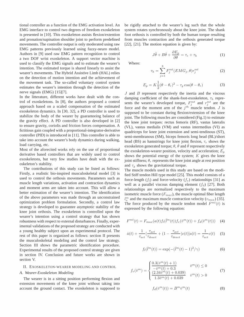
be rigidly attached to the wearer’s leg such that the wholesystem rotates synchronously about the knee joint. The shankfoot orthosis is controlled by both the human torque resultingfrom muscles contraction and the orthosis generated torque[22], [21]. The motion equation is given by:
Jθ + Bθ +∂Ep
∂θ= τe + τh (1)
Where:
τh =8
∑
j=1
Fmtj (EMGj , θ)r
mtj (2)
Ep = K1
2(θ − θr)
2 − τg cos(θ − θr) (3)
J and B represent respectively the inertia and the viscousdamping coefficient of the shank-foot-exoskeleton,τh repre-sents the wearer’s developed torque,Fmt
j and rmtj are the
force and the moment arm of thejth muscle tendon.J issupposed to be constant during flexion/extension of the kneejoint. The following muscles are considered (Fig.1) to estimatethe knee joint torques: rectus femoris (RF), vastus lateralis(VL), vastus medialis (VM) and vastus intermedius (VI) asquadriceps for knee joint extension and semi-tendinous (ST),semi-membranous (SM), biceps femoris long head (BL)/shorthead (BS) as hamstrings for knee joint flexion,τe shows theexoskeleton generated torque;θ, θ andθ represent respectivelythe exoskeleton-wearer position, velocity and acceleration;Ep
shows the potential energy of the system;K gives the kneejoint stiffness;θr represents the knee joint angle at rest positionandτg shows the gravitational torque.The muscle models used in this study are based on the modi-fied Stiff tendon Hill type model [25]. This model consists ofaforce-length (fl) and force-velocity (fv) relationships [31] aswell as a parallel viscous damping element (fd) [27]. Bothrelationships are normalized respectively to the maximumisometric muscle force (Fmax), the muscle optimal fiber lengthlmo and the maximum muscle contraction velocity (vmax) [35].The force produced by the muscle tendon modelFmt(t) isexpressed by the following equation:
Fmt(t) = Fmax(a(t)fl(lm(t))fv(vm(t)) + fd(v
m(t))) (4)
a(t) +1
τact
[τact
τdeact
+ (1 −τact
τdeact
)c(t)]a(t) =1
τact
c(t) (5)
fl(lm(t)) = exp(−(lm(t) − 1)2/γ) (6)
fv(vm) =
0.3(vm(t) + 1)
−vm(t) + 0.3vm(t) ≤ 0
(2.34vm(t) + 0.039)
1.3vm(t) + 0.039vm(t) > 0
(7)
fd(vm(t)) = Bmvm(t) (8)
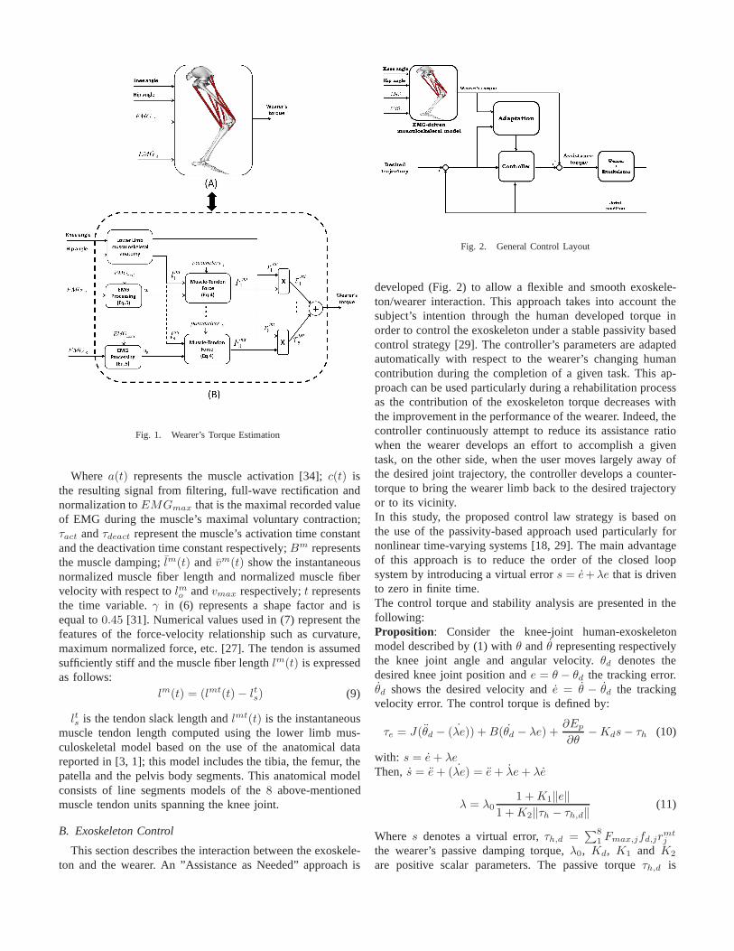
Fig. 1. Wearer’s Torque Estimation
Where a(t) represents the muscle activation [34];c(t) isthe resulting signal from filtering, full-wave rectification andnormalization toEMGmax that is the maximal recorded valueof EMG during the muscle’s maximal voluntary contraction;τact andτdeact represent the muscle’s activation time constantand the deactivation time constant respectively;Bm representsthe muscle damping;lm(t) and vm(t) show the instantaneousnormalized muscle fiber length and normalized muscle fibervelocity with respect tolmo andvmax respectively;t representsthe time variable.γ in (6) represents a shape factor and isequal to0.45 [31]. Numerical values used in (7) represent thefeatures of the force-velocity relationship such as curvature,maximum normalized force, etc. [27]. The tendon is assumedsufficiently stiff and the muscle fiber lengthlm(t) is expressedas follows:
lm(t) = (lmt(t) − lts) (9)
lts is the tendon slack length andlmt(t) is the instantaneousmuscle tendon length computed using the lower limb mus-culoskeletal model based on the use of the anatomical datareported in [3, 1]; this model includes the tibia, the femur,thepatella and the pelvis body segments. This anatomical modelconsists of line segments models of the8 above-mentionedmuscle tendon units spanning the knee joint.
B. Exoskeleton Control
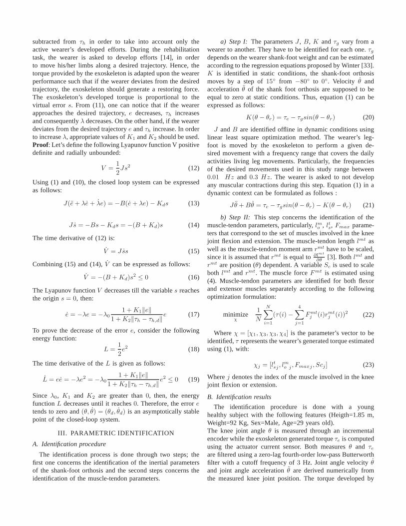
This section describes the interaction between the exoskele-ton and the wearer. An ”Assistance as Needed” approach is
Fig. 2. General Control Layout
developed (Fig. 2) to allow a flexible and smooth exoskele-ton/wearer interaction. This approach takes into account thesubject’s intention through the human developed torque inorder to control the exoskeleton under a stable passivity basedcontrol strategy [29]. The controller’s parameters are adaptedautomatically with respect to the wearer’s changing humancontribution during the completion of a given task. This ap-proach can be used particularly during a rehabilitation processas the contribution of the exoskeleton torque decreases withthe improvement in the performance of the wearer. Indeed, thecontroller continuously attempt to reduce its assistance ratiowhen the wearer develops an effort to accomplish a giventask, on the other side, when the user moves largely away ofthe desired joint trajectory, the controller develops a counter-torque to bring the wearer limb back to the desired trajectoryor to its vicinity.In this study, the proposed control law strategy is based onthe use of the passivity-based approach used particularly fornonlinear time-varying systems [18, 29]. The main advantageof this approach is to reduce the order of the closed loopsystem by introducing a virtual errors = e+λe that is drivento zero in finite time.The control torque and stability analysis are presented in thefollowing:Proposition: Consider the knee-joint human-exoskeletonmodel described by (1) withθ and θ representing respectivelythe knee joint angle and angular velocity.θd denotes thedesired knee joint position ande = θ − θd the tracking error.θd shows the desired velocity ande = θ − θd the trackingvelocity error. The control torque is defined by:
τe = J(θd − ˙(λe)) + B(θd − λe) +∂Ep
∂θ− Kds − τh (10)
with: s = e + λeThen, s = e + ˙(λe) = e + λe + λe
λ = λ0
1 + K1‖e‖
1 + K2‖τh − τh,d‖(11)
Where s denotes a virtual error,τh,d =∑8
1Fmax,jfd,jr
mtj
the wearer’s passive damping torque,λ0, Kd, K1 and K2
are positive scalar parameters. The passive torqueτh,d is
subtracted fromτh in order to take into account only theactive wearer’s developed efforts. During the rehabilitationtask, the wearer is asked to develop efforts [14], in orderto move his/her limbs along a desired trajectory. Hence, thetorque provided by the exoskeleton is adapted upon the wearerperformance such that if the wearer deviates from the desiredtrajectory, the exoskeleton should generate a restoring force.The exoskeleton’s developed torque is proportional to thevirtual error s. From (11), one can notice that if the wearerapproaches the desired trajectory,e decreases,τh increasesand consequentlyλ decreases. On the other hand, if the wearerdeviates from the desired trajectorye andτh increase. In orderto increaseλ, appropriate values ofK1 andK2 should be used.Proof: Let’s define the following Lyapunov function V positivedefinite and radially unbounded:
V =1
2Js2 (12)
Using (1) and (10), the closed loop system can be expressedas follows:
J(e + λe + λe) = −B(e + λe) − Kds (13)
Js = −Bs − Kds = −(B + Kd)s (14)
The time derivative of (12) is:
V = Jss (15)
Combining (15) and (14),V can be expressed as follows:
V = −(B + Kd)s2 ≤ 0 (16)
The Lyapunov functionV decreases till the variables reachesthe origins = 0, then:
e = −λe = −λ0
1 + K1‖e‖
1 + K2‖τh − τh,d‖e (17)
To prove the decrease of the errore, consider the followingenergy function:
L =1
2e2 (18)
The time derivative of theL is given as follows:
L = ee = −λe2 = −λ0
1 + K1‖e‖
1 + K2‖τh − τh,d‖e2 ≤ 0 (19)
Since λ0, K1 and K2 are greater than0, then, the energyfunctionL decreases until it reaches0. Therefore, the erroretends to zero and(θ, θ) = (θd, θd) is an asymptotically stablepoint of the closed-loop system.
III. PARAMETRIC IDENTIFICATION
A. Identification procedure
The identification process is done through two steps; thefirst one concerns the identification of the inertial parametersof the shank-foot orthosis and the second steps concerns theidentification of the muscle-tendon parameters.
a) Step I: The parametersJ , B, K andτg vary from awearer to another. They have to be identified for each one.τg
depends on the wearer shank-foot weight and can be estimatedaccording to the regression equations proposed by Winter [33].K is identified in static conditions, the shank-foot orthosismoves by a step of15◦ from −80◦ to 0◦. Velocity θ andaccelerationθ of the shank foot orthosis are supposed to beequal to zero at static conditions. Thus, equation (1) can beexpressed as follows:
K(θ − θr) = τe − τgsin(θ − θr) (20)
J andB are identified offline in dynamic conditions usinglinear least square optimization method. The wearer’s leg-foot is moved by the exoskeleton to perform a given de-sired movement with a frequency range that covers the dailyactivities living leg movements. Particularly, the frequenciesof the desired movements used in this study range between0.01 Hz and 0.3 Hz. The wearer is asked to not developany muscular contractions during this step. Equation (1) inadynamic context can be formulated as follows :
Jθ + Bθ = τe − τgsin(θ − θr) − K(θ − θr) (21)
b) Step II: This step concerns the identification of themuscle-tendon parameters, particularly,lmo , lts, Fmax parame-ters that correspond to the set of muscles involved in the kneejoint flexion and extension. The muscle-tendon lengthlmt aswell as the muscle-tendon moment armrmt have to be scaled,since it is assumed thatrmt is equal to∂lmt
∂θ[3]. Both lmt and
rmt are position (θ) dependent. A variableSc is used to scaleboth lmt and rmt. The muscle forceFmt is estimated using(4). Muscle-tendon parameters are identified for both flexorand extensor muscles separately according to the followingoptimization formulation:
minimizeχ
1
N
N∑
i=1
(τ(i) −4
∑
j=1
Fmtj (i)rmt
j (i))2 (22)
Whereχ = [χ1, χ3, χ3, χ4] is the parameter’s vector to beidentified,τ represents the wearer’s generated torque estimatedusing (1), with:
χj = [ltsj , lmo j , Fmaxj , Scj ] (23)
Wherej denotes the index of the muscle involved in the kneejoint flexion or extension.
B. Identification results
The identification procedure is done with a younghealthy subject with the following features (Heigth=1.85 m,Weight=92 Kg, Sex=Male, Age=29 years old).The knee joint angleθ is measured through an incrementalencoder while the exoskeleton generated torqueτe is computedusing the actuator current sensor. Both measuresθ and τe
are filtered using a zero-lag fourth-order low-pass Butterworthfilter with a cutoff frequency of3 Hz. Joint angle velocityθand joint angle accelerationθ are derived numerically fromthe measured knee joint position. The torque developed by
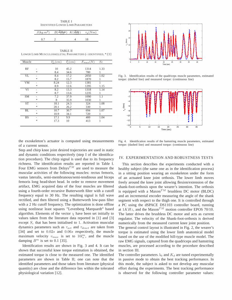
TABLE IIDENTIFIED LOWER L IMB PARAMETERS
J(kg.m2) B(Nm.srad
) K(Nmrad
) τg(Nm)
0.7 2 4 18
TABLE IILOWER L IMB MUSCULOSKELETALPARAMETERS (-:IDENTIFIED, *:[1]
Muscle lom(cm) lts(cm) Fmax(N) Sc
RF - 10 45.2 1314 1.33* 8.4 34.6 780 1
VL - 8.4 17.2 2050 1.02* 8.2 15.7 1870 1
VM - 8.24 12.3 1381 1* 8.9 12.6 1295 1.15
VI - 8.2 13.3 1318 1.14* 8.7 13.6 1235 1
SM - 7.2 37.9 1090 1.1* 8 35.9 1030 1
ST - 18.1 24.3 324 1.08* 20.1 26.2 330 1
BL - 10.7 30.7 694 1.07* 10.9 34.1 720 1
BS - 17.1 9.9 400 1.04* 17.3 10 413 1
the exoskeleton’s actuator is computed using measurementsof a current sensor.Step and chirp knee joint desired trajectories are used in staticand dynamic conditions respectively (step I of the identifica-tion procedure). The chirp signal is used due to its frequencyrichness. The identification results are reported in Table I.Four EMG sensors from DelsysTM are used to measure themuscular activities of the following muscles: rectus femoris,vastus lateralis, semi-membranous/semi-tendinous and bicepsfemoris long head/short head. In order to remove movementartifact, EMG acquired data of the four muscles are filteredusing a fourth-order recursive Butterworth filter with a cutofffrequency equal to 30 Hz. The resulting signal is full waverectified, and then filtered using a Butterworth low-pass filterwith a 2 Hz cutoff frequency. The optimization is done offlineusing nonlinear least squares ”Levenberg Marquardt” basedalgorithm. Elements of the vectorχ have been set initially tovalues taken from the literature data reported in [1] and [3]exceptSc that has been initialised to1. Activation musculardynamics parameters such asτact and τdeact are taken from[34] and set to0.02s and 0.06s respectively, the musclemaximum velocity vmax is set to 10lmo , and the muscledampingBm is set to 0.1 [35].
Identification results are shown in Fig. 3 and 4. It can beshown that successful knee torque estimation is obtained, theestimated torque is close to the measured one. The identifiedparameters are shown in Table II; one can note that theidentified parameters and those taken from literature (physicalquantity) are close and the difference lies within the toleratedphysiological variation [12].
0 5 10 15 20 25 30 35 40
0
5
10
15
20
25
τ h (
Nm
)
Time (sec)
Fig. 3. Identification results of the quadriceps muscle parameters, estimatedtorque: (dashed line) and measured torque: (continuous line)
0 5 10 15 20 25 30 35−14
−12
−10
−8
−6
−4
−2
0
τ h (
Nm
)
Time (sec)
Fig. 4. Identification results of the hamstring muscle parameters, estimatedtorque: (dashed line) and measured torque: (continuous line)
IV. EXPERIMENTATION AND ROBUSTNESS TESTS
This section describes the experiments conducted with ahealthy subject (the same one as in the identification process)in a sitting position wearing an exoskeleton under the formof an actuated knee joint orthosis. The lower limb movesfreely around the knee joint allowing flexion/extension of theshank-foot-orthosis upon the wearer’s intention. The orthosisis equipped with a MaxonTM brushless DC motor (BLDC)and an incremental encoder measuring the angle of the shanksegment with respect to the thigh one. It is controlled througha PC using the dSPACE DS1103 controller board, runningat 1KHz, and the MaxonTM motion controller EPOS 70/10.The latter drives the brushless DC motor and acts as currentregulator. The velocity of the Shank-foot-orthosis is derivednumerically from the measured current knee joint position.The general control layout is illustrated in Fig. 2, the wearer’storque is estimated using the lower limb anatomical modelbased on the use of the modified hill-type muscle model. Theraw EMG signals, captured from the quadriceps and hamstringmuscles, are processed according to the procedure describedin section III.The controller parametersλ0 andKd are tuned experimentallyin passive mode to obtain the best tracking performance. Inthis mode, the subject is asked to not develop any musculareffort during the experiments. The best tracking performanceis observed for the following controller parameter values:
0 10 20 30 40 50 60−100
−50
0
θ (
de
g)
(A)
0 10 20 30 40 50 60−10
0
10
e (
de
g)
(B)
0 10 20 30 40 50 60
0
20
40
τe (
Nm
)
(C)
0 10 20 30 40 50 600
10
20
τh (
Nm
)
(D)
0 10 20 30 40 50 60−0.5
0
0.5
EM
G (
RF
) (m
V) (E)
0 10 20 30 40 50 600
50
λ (
un
itle
ss)
(F)
Time (sec)
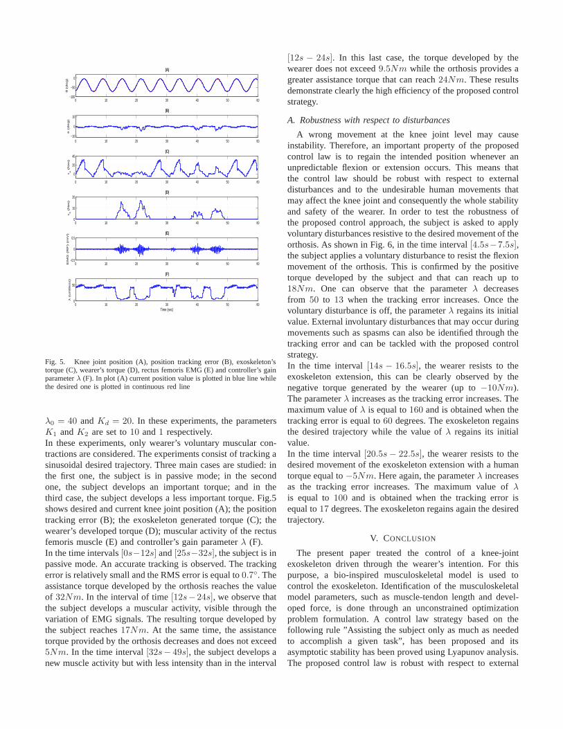
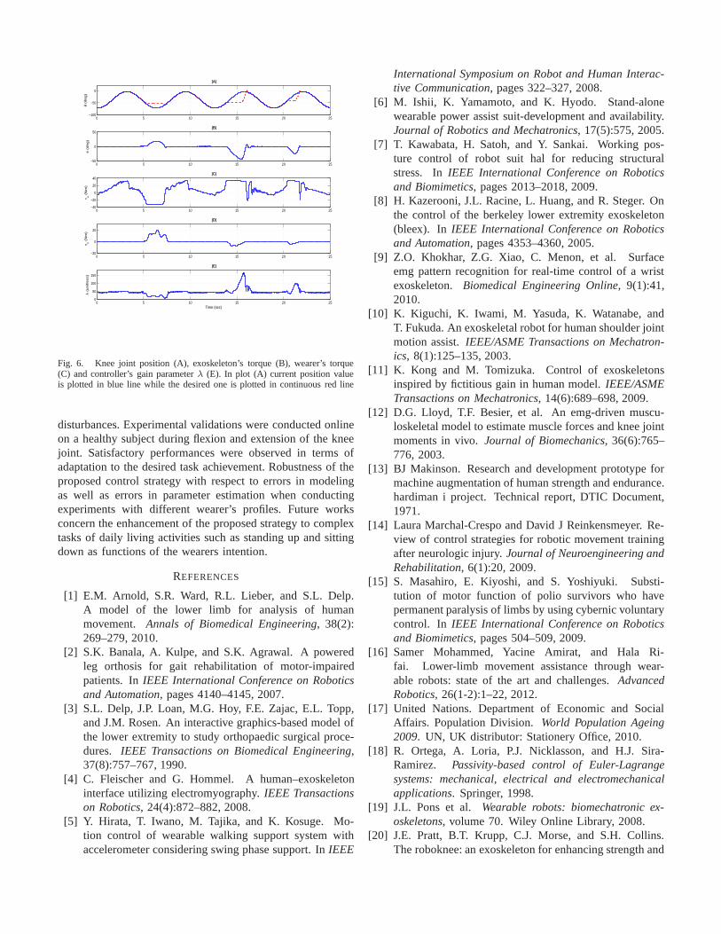
Fig. 5. Knee joint position (A), position tracking error (B), exoskeleton’storque (C), wearer’s torque (D), rectus femoris EMG (E) and controller’s gainparameterλ (F). In plot (A) current position value is plotted in blue line whilethe desired one is plotted in continuous red line
λ0 = 40 andKd = 20. In these experiments, the parametersK1 andK2 are set to10 and1 respectively.In these experiments, only wearer’s voluntary muscular con-tractions are considered. The experiments consist of tracking asinusoidal desired trajectory. Three main cases are studied: inthe first one, the subject is in passive mode; in the secondone, the subject develops an important torque; and in thethird case, the subject develops a less important torque. Fig.5shows desired and current knee joint position (A); the positiontracking error (B); the exoskeleton generated torque (C); thewearer’s developed torque (D); muscular activity of the rectusfemoris muscle (E) and controller’s gain parameterλ (F).In the time intervals[0s−12s] and[25s−32s], the subject is inpassive mode. An accurate tracking is observed. The trackingerror is relatively small and the RMS error is equal to0.7◦. Theassistance torque developed by the orthosis reaches the valueof 32Nm. In the interval of time[12s−24s], we observe thatthe subject develops a muscular activity, visible through thevariation of EMG signals. The resulting torque developed bythe subject reaches17Nm. At the same time, the assistancetorque provided by the orthosis decreases and does not exceed5Nm. In the time interval[32s− 49s], the subject develops anew muscle activity but with less intensity than in the interval
[12s − 24s]. In this last case, the torque developed by thewearer does not exceed9.5Nm while the orthosis provides agreater assistance torque that can reach24Nm. These resultsdemonstrate clearly the high efficiency of the proposed controlstrategy.
A. Robustness with respect to disturbances
A wrong movement at the knee joint level may causeinstability. Therefore, an important property of the proposedcontrol law is to regain the intended position whenever anunpredictable flexion or extension occurs. This means thatthe control law should be robust with respect to externaldisturbances and to the undesirable human movements thatmay affect the knee joint and consequently the whole stabilityand safety of the wearer. In order to test the robustness ofthe proposed control approach, the subject is asked to applyvoluntary disturbances resistive to the desired movement of theorthosis. As shown in Fig. 6, in the time interval[4.5s−7.5s],the subject applies a voluntary disturbance to resist the flexionmovement of the orthosis. This is confirmed by the positivetorque developed by the subject and that can reach up to18Nm. One can observe that the parameterλ decreasesfrom 50 to 13 when the tracking error increases. Once thevoluntary disturbance is off, the parameterλ regains its initialvalue. External involuntary disturbances that may occur duringmovements such as spasms can also be identified through thetracking error and can be tackled with the proposed controlstrategy.In the time interval[14s − 16.5s], the wearer resists to theexoskeleton extension, this can be clearly observed by thenegative torque generated by the wearer (up to−10Nm).The parameterλ increases as the tracking error increases. Themaximum value ofλ is equal to160 and is obtained when thetracking error is equal to60 degrees. The exoskeleton regainsthe desired trajectory while the value ofλ regains its initialvalue.In the time interval[20.5s − 22.5s], the wearer resists to thedesired movement of the exoskeleton extension with a humantorque equal to−5Nm. Here again, the parameterλ increasesas the tracking error increases. The maximum value ofλis equal to100 and is obtained when the tracking error isequal to17 degrees. The exoskeleton regains again the desiredtrajectory.
V. CONCLUSION
The present paper treated the control of a knee-jointexoskeleton driven through the wearer’s intention. For thispurpose, a bio-inspired musculoskeletal model is used tocontrol the exoskeleton. Identification of the musculoskeletalmodel parameters, such as muscle-tendon length and devel-oped force, is done through an unconstrained optimizationproblem formulation. A control law strategy based on thefollowing rule ”Assisting the subject only as much as neededto accomplish a given task”, has been proposed and itsasymptotic stability has been proved using Lyapunov analysis.The proposed control law is robust with respect to external
0 5 10 15 20 25−100
−50
0
θ (d
eg
) (A)
0 5 10 15 20 25−50
0
50
e (
de
g)
(B)
0 5 10 15 20 25−40
−20
0
20
40
τ e (
Nm
)
(C)
0 5 10 15 20 25−20
0
20
τ h (
Nm
)
(D)
0 5 10 15 20 250
50
100
150
λ (
un
itle
ss)
(E)
Time (sec)
Fig. 6. Knee joint position (A), exoskeleton’s torque (B), wearer’s torque(C) and controller’s gain parameterλ (E). In plot (A) current position valueis plotted in blue line while the desired one is plotted in continuous red line
disturbances. Experimental validations were conducted onlineon a healthy subject during flexion and extension of the kneejoint. Satisfactory performances were observed in terms ofadaptation to the desired task achievement. Robustness of theproposed control strategy with respect to errors in modelingas well as errors in parameter estimation when conductingexperiments with different wearer’s profiles. Future worksconcern the enhancement of the proposed strategy to complextasks of daily living activities such as standing up and sittingdown as functions of the wearers intention.
REFERENCES
[1] E.M. Arnold, S.R. Ward, R.L. Lieber, and S.L. Delp.A model of the lower limb for analysis of humanmovement. Annals of Biomedical Engineering, 38(2):269–279, 2010.
[2] S.K. Banala, A. Kulpe, and S.K. Agrawal. A poweredleg orthosis for gait rehabilitation of motor-impairedpatients. InIEEE International Conference on Roboticsand Automation, pages 4140–4145, 2007.
[3] S.L. Delp, J.P. Loan, M.G. Hoy, F.E. Zajac, E.L. Topp,and J.M. Rosen. An interactive graphics-based model ofthe lower extremity to study orthopaedic surgical proce-dures. IEEE Transactions on Biomedical Engineering,37(8):757–767, 1990.
[4] C. Fleischer and G. Hommel. A human–exoskeletoninterface utilizing electromyography.IEEE Transactionson Robotics, 24(4):872–882, 2008.
[5] Y. Hirata, T. Iwano, M. Tajika, and K. Kosuge. Mo-tion control of wearable walking support system withaccelerometer considering swing phase support. InIEEE
International Symposium on Robot and Human Interac-tive Communication, pages 322–327, 2008.
[6] M. Ishii, K. Yamamoto, and K. Hyodo. Stand-alonewearable power assist suit-development and availability.Journal of Robotics and Mechatronics, 17(5):575, 2005.
[7] T. Kawabata, H. Satoh, and Y. Sankai. Working pos-ture control of robot suit hal for reducing structuralstress. InIEEE International Conference on Roboticsand Biomimetics, pages 2013–2018, 2009.
[8] H. Kazerooni, J.L. Racine, L. Huang, and R. Steger. Onthe control of the berkeley lower extremity exoskeleton(bleex). In IEEE International Conference on Roboticsand Automation, pages 4353–4360, 2005.
[9] Z.O. Khokhar, Z.G. Xiao, C. Menon, et al. Surfaceemg pattern recognition for real-time control of a wristexoskeleton. Biomedical Engineering Online, 9(1):41,2010.
[10] K. Kiguchi, K. Iwami, M. Yasuda, K. Watanabe, andT. Fukuda. An exoskeletal robot for human shoulder jointmotion assist.IEEE/ASME Transactions on Mechatron-ics, 8(1):125–135, 2003.
[11] K. Kong and M. Tomizuka. Control of exoskeletonsinspired by fictitious gain in human model.IEEE/ASMETransactions on Mechatronics, 14(6):689–698, 2009.
[12] D.G. Lloyd, T.F. Besier, et al. An emg-driven muscu-loskeletal model to estimate muscle forces and knee jointmoments in vivo.Journal of Biomechanics, 36(6):765–776, 2003.
[13] BJ Makinson. Research and development prototype formachine augmentation of human strength and endurance.hardiman i project. Technical report, DTIC Document,1971.
[14] Laura Marchal-Crespo and David J Reinkensmeyer. Re-view of control strategies for robotic movement trainingafter neurologic injury.Journal of Neuroengineering andRehabilitation, 6(1):20, 2009.
[15] S. Masahiro, E. Kiyoshi, and S. Yoshiyuki. Substi-tution of motor function of polio survivors who havepermanent paralysis of limbs by using cybernic voluntarycontrol. In IEEE International Conference on Roboticsand Biomimetics, pages 504–509, 2009.
[16] Samer Mohammed, Yacine Amirat, and Hala Ri-fai. Lower-limb movement assistance through wear-able robots: state of the art and challenges.AdvancedRobotics, 26(1-2):1–22, 2012.
[17] United Nations. Department of Economic and SocialAffairs. Population Division. World Population Ageing2009. UN, UK distributor: Stationery Office, 2010.
[18] R. Ortega, A. Loria, P.J. Nicklasson, and H.J. Sira-Ramirez. Passivity-based control of Euler-Lagrangesystems: mechanical, electrical and electromechanicalapplications. Springer, 1998.
[19] J.L. Pons et al. Wearable robots: biomechatronic ex-oskeletons, volume 70. Wiley Online Library, 2008.
[20] J.E. Pratt, B.T. Krupp, C.J. Morse, and S.H. Collins.The roboknee: an exoskeleton for enhancing strength and
endurance during walking. InIEEE International Con-ference on Robotics and Automation, volume 3, pages2430–2435, 2004.
[21] Hala Rifai, Walid Hassani, Samer Mohammed, andYacine Amirat. Bounded control of an actuated lowerlimb orthosis. InDecision and Control and EuropeanControl Conference (CDC-ECC), 2011 50th IEEE Con-ference on, pages 873–878, 2011.
[22] Hala Rifai, Samer Mohammed, Boubaker Daachi, andYacine Amirat. Adaptive control of a human-driven kneejoint orthosis. InRobotics and Automation (ICRA), 2012IEEE International Conference on, pages 2486–2491,2012.
[23] J. Rosen, M.B. Fuchs, and M. Arcan. Performancesof hill-type and neural network muscle modelstoward amyosignal-based exoskeleton.Computers and Biomedi-cal Research, 32(5):415–439, 1999.
[24] J. Rosen, M. Brand, M.B. Fuchs, and M. Arcan. Amyosignal-based powered exoskeleton system.IEEETransactions on Systems, Man and Cybernetics, Part A:Systems and Humans, 31(3):210–222, 2001.
[25] M. Sartori, D.G. Lloyd, M. Reggiani, and E. Pagello.A stiff tendon neuromusculoskeletal model of the knee.In IEEE Workshop on Advanced Robotics and its SocialImpacts, pages 132–138, 2009.
[26] G.S. Sawicki, K.E. Gordon, and D.P. Ferris. Poweredlower limb orthoses: applications in motor adaptation andrehabilitation. InInternational Conference on Rehabili-tation Robotics, pages 206–211, 2005.
[27] L.M. Schutte. Using Musculoskeletal Models toExplore Strategies for Improving Performancein Electrical Stimulation-induced Leg CycleErgometry. Stanford University, 1993. URLhttp://books.google.fr/books?id=UWnItgAACAAJ.
[28] A. Seireg and RJ Arvikar. The prediction of muscularload sharing and joint forces in the lower extremitiesduring walking. Journal of Biomechanics, 8(2):89–102,1975.
[29] J.J.E. Slotine and L. Weiping. Adaptive manipulatorcontrol: A case study.IEEE Transactions on AutomaticControl, 33(11):995–1003, 1988.
[30] K. Suzuki, G. Mito, H. Kawamoto, Y. Hasegawa, andY. Sankai. Intention-based walking support for paraplegiapatients with robot suit hal.Advanced Robotics, 21(12):1441–1469, 2007.
[31] D.G. Thelen et al. Adjustment of muscle mechanicsmodel parameters to simulate dynamic contractions inolder adults.Transactions-American Society of Mechan-ical Engineers - Journal of Biomechanical Engineering,125(1):70–77, 2003.
[32] A. Tsukahara, R. Kawanishi, Y. Hasegawa, andY. Sankai. Sit-to-stand and stand-to-sit transfer supportfor complete paraplegic patients with robot suit hal.Advanced robotics, 24(11):1615–1638, 2010.
[33] D.A. Winter. Biomechanics and motor control of humanmovement. Wiley, 2009.
[34] G.T. Yamaguchi.Dynamic modeling of musculoskeletalmotion: a vectorized approach for biomechanical anal-ysis in three dimensions. Kluwer Academic PublishersNorwell, MA, 2001.
[35] F.E. Zajac et al. Muscle and tendon: properties, models,scaling, and application to biomechanics and motor con-trol. Critical reviews in biomedical engineering, 17(4):359, 1989.