Embed Size (px)
Citation preview
Förstner 229
Real-Time Photogrammetry
WOLFGANG FÖRSTNER, Bonn
ABSTRACT Today’s speed of image processing tools as well as the availability of robust techniques for extracting geometric and basic thematic information from image streams makes real-time photogrammetry possible. The paper discusses the basic tools for fully automatic calibration, orientation and surface recontruction as well as for tracking, ego-motion determination and behaviour analysis. Examples demonstrate today’s potential for future applications.
1. INTRODUCTION
Real-time photogrammetry has been a dream since its beginning. The technological developments on the last few years make the realization of this dream possible. This paper gives a glance on the state of the art motivating the next steps in automation of photogrammetry. The difficulty of automating photogrammetric tasks varies largely: Interpretation tasks still require a human operator, whereas tasks, where no interpretation of the image content is necessary, are autotomated to a high degree. As an example, software for automated aerotriangulation and surface reconstruction is commercially available, whereas mapping software only marginally contains tools for semi-automation. In close range photogrammetry the situation is even more pronounced: Auto-matic orientation and measuring procedures often rely on targeted and coded points. Laser range sensing though directly yielding 3D-information makes no exception: Whereas automatic tools for matching neighbouring point clouds are available (BENDELS ET AL. 2004) the interpretation of point clouds also is still at its beginning. Real-time requires automation where the result is available in time for making decisions. The cur-rent cycles for updating maps are the result of both, technological – and financial – boundary condi-tions and the requirement for timeliness, which allows at least days, weeks or months for image evaluation. On the other hand mapping on demand becomes a must in disaster management, naviga-tion, surveillance or vehicle control. Here image evaluation needs to go at the border of today’s technology in order to fulfil the requirements, e. g. providing maps in a few hours, determining sur-faces in seconds or tracking objects at video rate. The need for real-time image evaluation not only increases, fortunately it can be realized to a large extent.
1.1. Real-Time Photogrammetry in the past
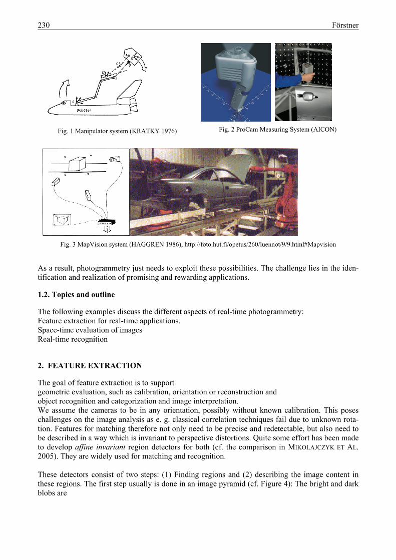
Real-time photogrammetry is no new topic. A. GRÜN evaluated the current state in his paper on the Photogrammetric Week 1987: 90 % was devoted to the technological boundaries: image acquisition (frame grabbers), image size (far below 1 million pixels), speed (special hardware and parallel processing) , accuracy of point positioning (0.1 pixel) and price (starting at 500 $ going up to 40 000 $). Kratky (1976) reports on an on-line system for controlling the manipulator system of the Space Shuttle Orbiter based on a vidicon camera (cf. Figure 1). The MapVision System of Haggren (1986, cf. Figure 3) is a multi-video-camera system measuring targeted points by forward intersec-tion within a second. AICON’s ProCam System is based on real-time spatial resection to coded tar-gets for positioning the measuring head (cf. Figure 2).
'Photogrammetric Week 05' Dieter Fritsch, Ed. Wichmann Verlag, Heidelberg 2005.
230 Förstner
Fig. 1 Manipulator system (KRATKY 1976)
Fig. 2 ProCam Measuring System (AICON)
Fig. 3 MapVision system (HAGGREN 1986), http://foto.hut.fi/opetus/260/luennot/9/9.html#Mapvision
As a result, photogrammetry just needs to exploit these possibilities. The challenge lies in the iden-tification and realization of promising and rewarding applications.
1.2. Topics and outline
The following examples discuss the different aspects of real-time photogrammetry: Feature extraction for real-time applications. Space-time evaluation of images Real-time recognition
2. FEATURE EXTRACTION
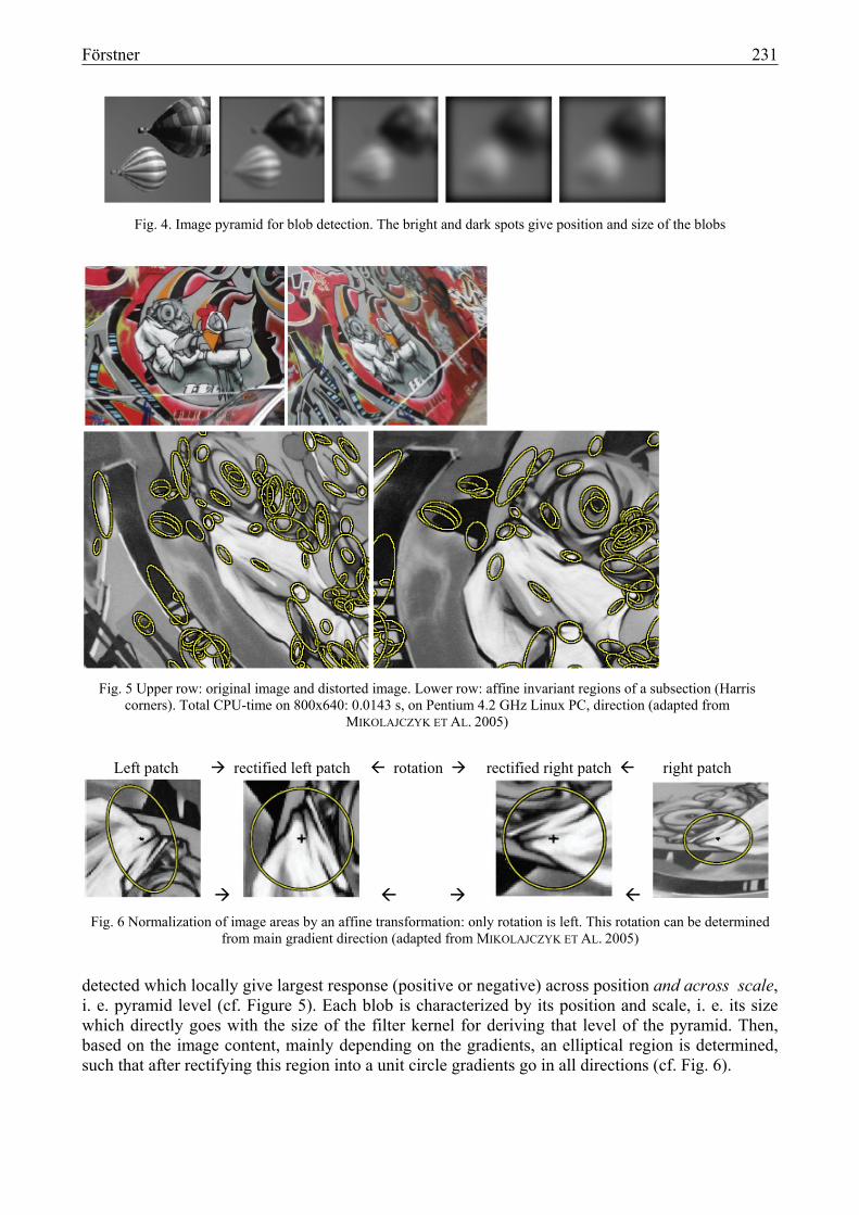
The goal of feature extraction is to support geometric evaluation, such as calibration, orientation or reconstruction and object recognition and categorization and image interpretation. We assume the cameras to be in any orientation, possibly without known calibration. This poses challenges on the image analysis as e. g. classical correlation techniques fail due to unknown rota-tion. Features for matching therefore not only need to be precise and redetectable, but also need to be described in a way which is invariant to perspective distortions. Quite some effort has been made to develop affine invariant region detectors for both (cf. the comparison in MIKOLAJCZYK ET AL. 2005). They are widely used for matching and recognition. These detectors consist of two steps: (1) Finding regions and (2) describing the image content in these regions. The first step usually is done in an image pyramid (cf. Figure 4): The bright and dark blobs are
Förstner 231
Fig. 4. Image pyramid for blob detection. The bright and dark spots give position and size of the blobs
Fig. 5 Upper row: original image and distorted image. Lower row: affine invariant regions of a subsection (Harris
corners). Total CPU-time on 800x640: 0.0143 s, on Pentium 4.2 GHz Linux PC, direction (adapted from MIKOLAJCZYK ET AL. 2005)
Left patch rectified left patch rotation rectified right patch right patch
Fig. 6 Normalization of image areas by an affine transformation: only rotation is left. This rotation can be determined
from main gradient direction (adapted from MIKOLAJCZYK ET AL. 2005)
detected which locally give largest response (positive or negative) across position and across scale, i. e. pyramid level (cf. Figure 5). Each blob is characterized by its position and scale, i. e. its size which directly goes with the size of the filter kernel for deriving that level of the pyramid. Then, based on the image content, mainly depending on the gradients, an elliptical region is determined, such that after rectifying this region into a unit circle gradients go in all directions (cf. Fig. 6).
232 Förstner
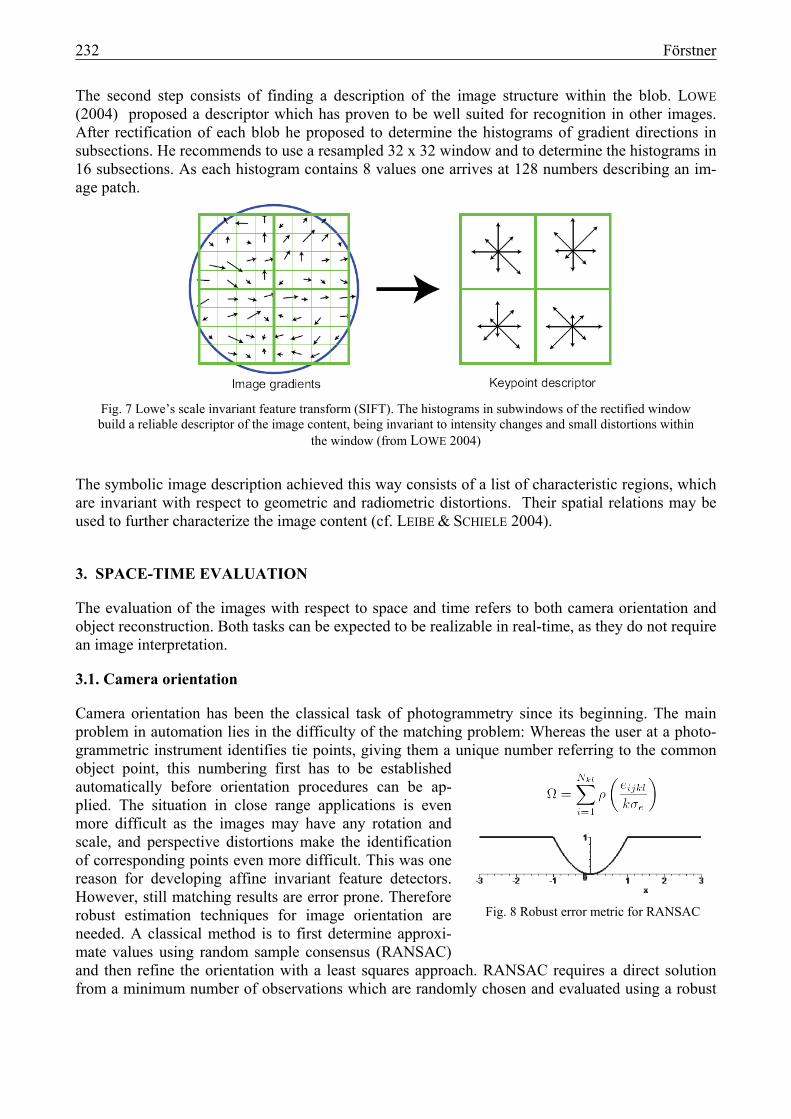
The second step consists of finding a description of the image structure within the blob. LOWE (2004) proposed a descriptor which has proven to be well suited for recognition in other images. After rectification of each blob he proposed to determine the histograms of gradient directions in subsections. He recommends to use a resampled 32 x 32 window and to determine the histograms in 16 subsections. As each histogram contains 8 values one arrives at 128 numbers describing an im-age patch.
Fig. 7 Lowe’s scale invariant feature transform (SIFT). The histograms in subwindows of the rectified window build a reliable descriptor of the image content, being invariant to intensity changes and small distortions within
the window (from LOWE 2004)
The symbolic image description achieved this way consists of a list of characteristic regions, which are invariant with respect to geometric and radiometric distortions. Their spatial relations may be used to further characterize the image content (cf. LEIBE & SCHIELE 2004).
3. SPACE-TIME EVALUATION
The evaluation of the images with respect to space and time refers to both camera orientation and object reconstruction. Both tasks can be expected to be realizable in real-time, as they do not require an image interpretation.
3.1. Camera orientation
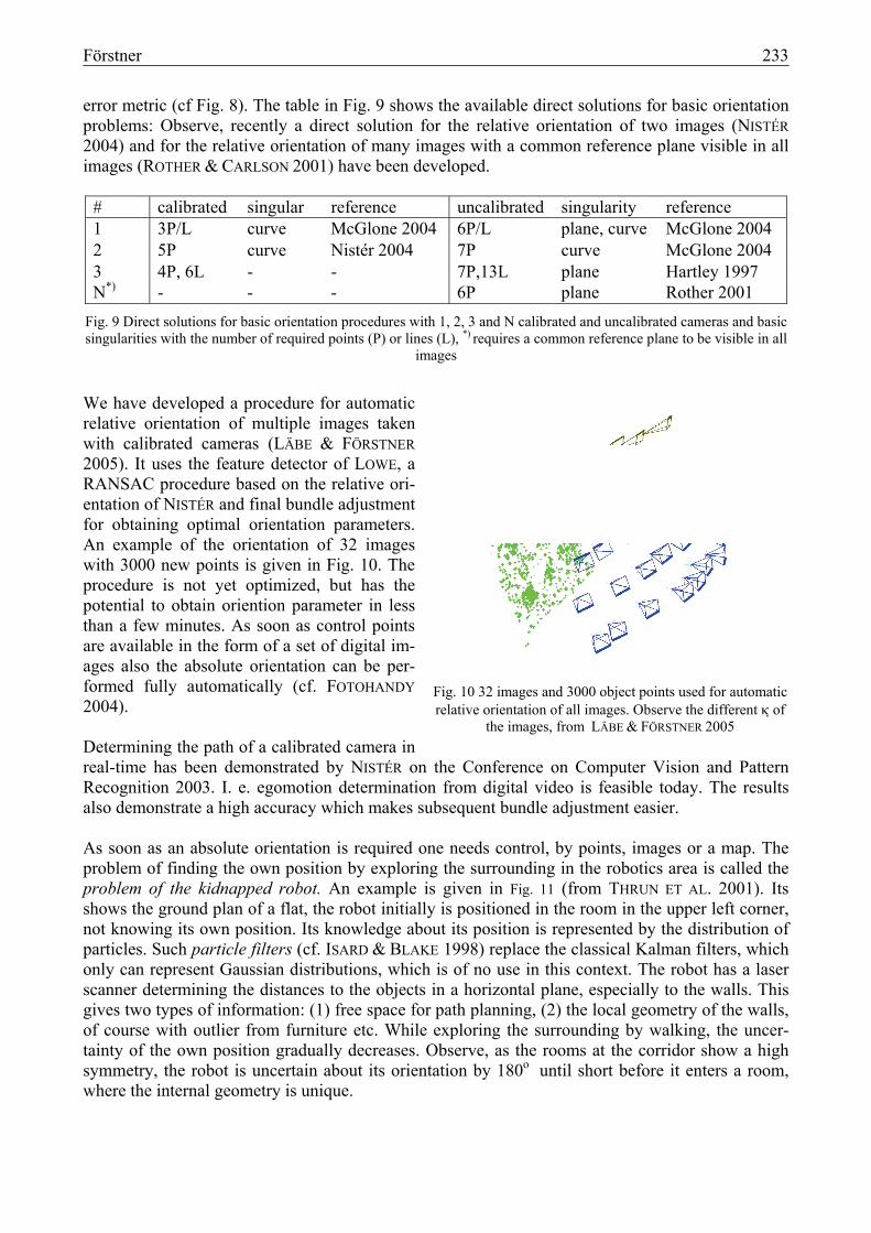
Camera orientation has been the classical task of photogrammetry since its beginning. The main problem in automation lies in the difficulty of the matching problem: Whereas the user at a photo-grammetric instrument identifies tie points, giving them a unique number referring to the common object point, this numbering first has to be established automatically before orientation procedures can be ap-plied. The situation in close range applications is even more difficult as the images may have any rotation and scale, and perspective distortions make the identification of corresponding points even more difficult. This was one reason for developing affine invariant feature detectors. However, still matching results are error prone. Therefore robust estimation techniques for image orientation are needed. A classical method is to first determine approxi-mate values using random sample consensus (RANSAC) and then refine the orientation with a least squares approach. RANSAC requires a direct solution from a minimum number of observations which are randomly chosen and evaluated using a robust
Fig. 8 Robust error metric for RANSAC
Förstner 233
error metric (cf Fig. 8). The table in Fig. 9 shows the available direct solutions for basic orientation problems: Observe, recently a direct solution for the relative orientation of two images (NISTÉR 2004) and for the relative orientation of many images with a common reference plane visible in all images (ROTHER & CARLSON 2001) have been developed.
# calibrated singular reference uncalibrated singularity reference 1 3P/L curve McGlone 2004 6P/L plane, curve McGlone 2004 2 5P curve Nistér 2004 7P curve McGlone 2004 3 4P, 6L - - 7P,13L plane Hartley 1997 N*) - - - 6P plane Rother 2001
Fig. 9 Direct solutions for basic orientation procedures with 1, 2, 3 and N calibrated and uncalibrated cameras and basic singularities with the number of required points (P) or lines (L), *) requires a common reference plane to be visible in all
images
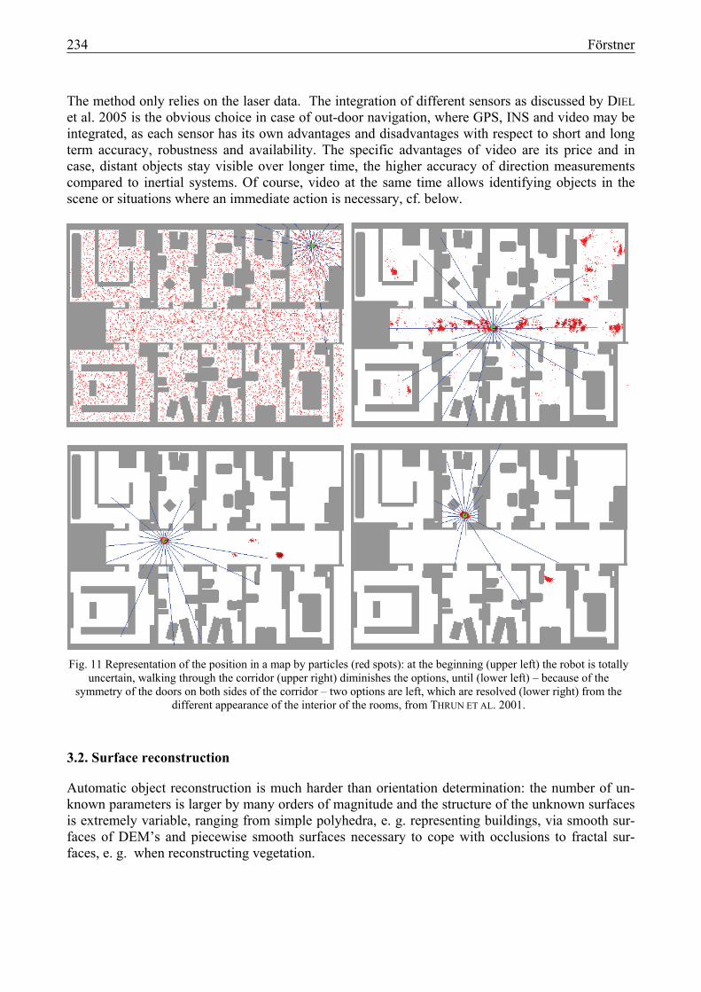
We have developed a procedure for automatic relative orientation of multiple images taken with calibrated cameras (LÄBE & FÖRSTNER 2005). It uses the feature detector of LOWE, a RANSAC procedure based on the relative ori-entation of NISTÉR and final bundle adjustment for obtaining optimal orientation parameters. An example of the orientation of 32 images with 3000 new points is given in Fig. 10. The procedure is not yet optimized, but has the potential to obtain oriention parameter in less than a few minutes. As soon as control points are available in the form of a set of digital im-ages also the absolute orientation can be per-formed fully automatically (cf. FOTOHANDY 2004). Determining the path of a calibrated camera in real-time has been demonstrated by NISTÉR on the Conference on Computer Vision and Pattern Recognition 2003. I. e. egomotion determination from digital video is feasible today. The results also demonstrate a high accuracy which makes subsequent bundle adjustment easier. As soon as an absolute orientation is required one needs control, by points, images or a map. The problem of finding the own position by exploring the surrounding in the robotics area is called the problem of the kidnapped robot. An example is given in Fig. 11 (from THRUN ET AL. 2001). Its shows the ground plan of a flat, the robot initially is positioned in the room in the upper left corner, not knowing its own position. Its knowledge about its position is represented by the distribution of particles. Such particle filters (cf. ISARD & BLAKE 1998) replace the classical Kalman filters, which only can represent Gaussian distributions, which is of no use in this context. The robot has a laser scanner determining the distances to the objects in a horizontal plane, especially to the walls. This gives two types of information: (1) free space for path planning, (2) the local geometry of the walls, of course with outlier from furniture etc. While exploring the surrounding by walking, the uncer-tainty of the own position gradually decreases. Observe, as the rooms at the corridor show a high symmetry, the robot is uncertain about its orientation by 180o until short before it enters a room, where the internal geometry is unique.
Fig. 10 32 images and 3000 object points used for automatic relative orientation of all images. Observe the different κ of
the images, from LÄBE & FÖRSTNER 2005
234 Förstner
The method only relies on the laser data. The integration of different sensors as discussed by DIEL et al. 2005 is the obvious choice in case of out-door navigation, where GPS, INS and video may be integrated, as each sensor has its own advantages and disadvantages with respect to short and long term accuracy, robustness and availability. The specific advantages of video are its price and in case, distant objects stay visible over longer time, the higher accuracy of direction measurements compared to inertial systems. Of course, video at the same time allows identifying objects in the scene or situations where an immediate action is necessary, cf. below.
Fig. 11 Representation of the position in a map by particles (red spots): at the beginning (upper left) the robot is totally
uncertain, walking through the corridor (upper right) diminishes the options, until (lower left) – because of the symmetry of the doors on both sides of the corridor – two options are left, which are resolved (lower right) from the
different appearance of the interior of the rooms, from THRUN ET AL. 2001.
3.2. Surface reconstruction
Automatic object reconstruction is much harder than orientation determination: the number of un-known parameters is larger by many orders of magnitude and the structure of the unknown surfaces is extremely variable, ranging from simple polyhedra, e. g. representing buildings, via smooth sur-faces of DEM’s and piecewise smooth surfaces necessary to cope with occlusions to fractal sur-faces, e. g. when reconstructing vegetation.
Förstner 235
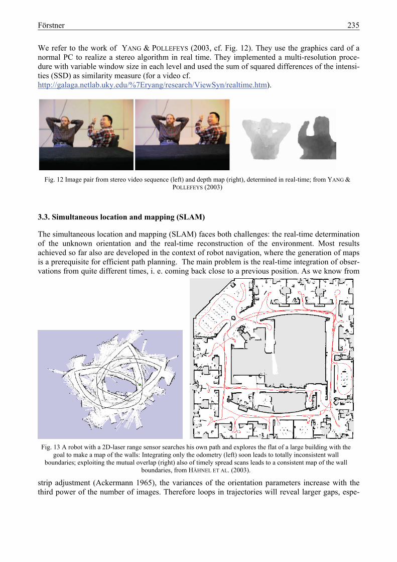
We refer to the work of YANG & POLLEFEYS (2003, cf. Fig. 12). They use the graphics card of a normal PC to realize a stereo algorithm in real time. They implemented a multi-resolution proce-dure with variable window size in each level and used the sum of squared differences of the intensi-ties (SSD) as similarity measure (for a video cf. http://galaga.netlab.uky.edu/%7Eryang/research/ViewSyn/realtime.htm).
Fig. 12 Image pair from stereo video sequence (left) and depth map (right), determined in real-time; from YANG &
POLLEFEYS (2003)
3.3. Simultaneous location and mapping (SLAM)
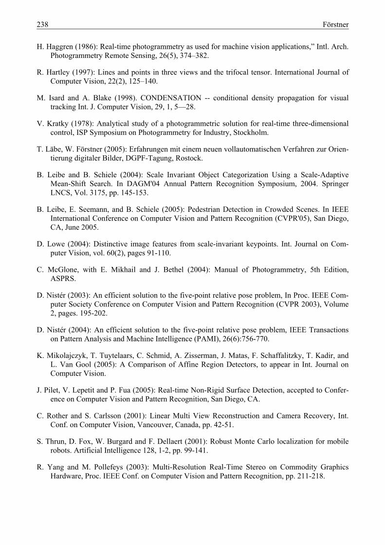
The simultaneous location and mapping (SLAM) faces both challenges: the real-time determination of the unknown orientation and the real-time reconstruction of the environment. Most results achieved so far also are developed in the context of robot navigation, where the generation of maps is a prerequisite for efficient path planning. The main problem is the real-time integration of obser-vations from quite different times, i. e. coming back close to a previous position. As we know from
strip adjustment (Ackermann 1965), the variances of the orientation parameters increase with the third power of the number of images. Therefore loops in trajectories will reveal larger gaps, espe-
Fig. 13 A robot with a 2D-laser range sensor searches his own path and explores the flat of a large building with the goal to make a map of the walls: Integrating only the odometry (left) soon leads to totally inconsistent wall
boundaries; exploiting the mutual overlap (right) also of timely spread scans leads to a consistent map of the wall boundaries, from HÄHNEL ET AL. (2003).

236 Förstner
cially in case the local orientation, e. g. with odometry is weak. The hard problem is the representa-tion of the history of the acquired map. An example is taken from HÄHNEL ET AL. (2003), cf. Fig. 13. The task of the robot is to build a map during exploring the flat of a building. As the path of the robot is uncertain and needs to be im-proved over time, a stochastic representation for the path is chosen. For this the path is partitioned into local stable parts, their distribution over space is represented by particles, as done for the posi-tion in the above mentioned localization example. This distribution is estimated over time using a particle filter. This sparse representation allows real time processing (for an animation cf. http://www.informatik.uni-freiburg.de/~haehnel/research/scan-matching-fastslam/).
4. REAL-TIME DETECTION
The space-time reconstruction, discussed in the previous section, usually is only a part in a large system which requires decision making, e. g. in car or pedestrian navigation or in building surveil-lance. Real-time detection is a first step, namely just finding position and time of a given object in an image or an image sequence, e. g. obstacle detection in navigation. Recognizing specific objects, e. g. road signs, is a task requiring more knowledge, and therefore can be expected to be more diffi-cult. Categorization, i. e. identifying the class an object belongs to, is even more involving and topic of current research. The first example shows, that detection is possible in the presence of deformations of the object (cf. Fig. 14, from PILET ET AL. 2005). The object, here a deformable textured paper, can be identified in the video, as soon at it appears in the field of view of the camera. The matching is performed on a crowd of interest points. The second example wants to show, that detection of multiple objects in complex environments is possible (cf. from LEIBE ET AL. 2005). Here, also the shape of pedestrians is stored as a set of inter-est points, together with their mutual geometric relations.
Fig. 14 Real-time detection of deformed objects: as soon as the object appears in the view of the camera it is detected and its deformation is estimated, from PILET ET AL. 2005. The left image shows the current window, the right image.
The lines are calculated in real-time, showing the correctness of the correspondence.

Förstner 237
5. CONCLUSION
The goal of the paper was to demonstrate current research in real-time image analysis. Some of the shown results are immediately transferable to Photogrammetric applications. Others, quite promis-ing results, still need some engineering to increase flexibility and robustness. The examples should stimulate research and development in this highly fascinating area.
Fig. 15 Detection of multiple pedestrians in crowded scenes (from LEIBE ET AL. 2005)
6. REFERENCES
F. Ackermann, (1965): Fehlertheoretische Untersuchungen über die Genauigkeit photogrammetri-scher Streifentriangulationen. Deutsche Geodätische Kommission, Reihe C, Nr. 87, München 1965.
G. H. Bendels, P. Degener, R. Wahl, M. Körtgen, R. Klein (2004): Image-Based Registration of 3D-Range Data Using Feature Surface Elements, in Y. Chrysanthou, K. Cain, N. Silberman, F. Niccolucci, editor(s): Proceedings of 5th International Symposium on Virtual Reality, Archae-ology and Cultural Heritage (VAST 2004), p. 115-12.
D. D. Diel, P. DeBitetto, S. Teller (2005): Epipolar Constraints for Vision-Aided Inertial Naviga-tion, Proceedings of the IEEE Workshop on Motion and Video Computing.
R. Fischler, R. C. Bolles (1981): Random Sample Consensus: A Paradigm for Model Fitting with Applications to image Analysis and Automated Cartography. Comm. of the ACM, Vol. 24, S. 381-395.
Fotohandy (2004): http://www.ipb.uni-bonn.de/Teaching/vertiefung/SS04/vertiefer04/, July 2005.
A. Grün (1987): Towards Real Time Photogrammetry, Photogrammetric Week 1987, Schriftenreihe des Instituts für Photogrammetrie, Heft 12.
D. Hähnel, D. Fox, W. Burgard, and S. Thrun (2003): A highly efficient FastSLAM algorithm for generating cyclic maps of large-scale environments from raw laser range measurements , in Proc. of the Conference on Intelligent Robots and Systems (IROS).
238 Förstner
H. Haggren (1986): Real-time photogrammetry as used for machine vision applications,” Intl. Arch. Photogrammetry Remote Sensing, 26(5), 374–382.
R. Hartley (1997): Lines and points in three views and the trifocal tensor. International Journal of Computer Vision, 22(2), 125–140.
M. Isard and A. Blake (1998). CONDENSATION -- conditional density propagation for visual tracking Int. J. Computer Vision, 29, 1, 5—28.
V. Kratky (1978): Analytical study of a photogrammetric solution for real-time three-dimensional control, ISP Symposium on Photogrammetry for Industry, Stockholm.
T. Läbe, W. Förstner (2005): Erfahrungen mit einem neuen vollautomatischen Verfahren zur Orien-tierung digitaler Bilder, DGPF-Tagung, Rostock.
B. Leibe and B. Schiele (2004): Scale Invariant Object Categorization Using a Scale-Adaptive Mean-Shift Search. In DAGM'04 Annual Pattern Recognition Symposium, 2004. Springer LNCS, Vol. 3175, pp. 145-153.
B. Leibe, E. Seemann, and B. Schiele (2005): Pedestrian Detection in Crowded Scenes. In IEEE International Conference on Computer Vision and Pattern Recognition (CVPR'05), San Diego, CA, June 2005.
D. Lowe (2004): Distinctive image features from scale-invariant keypoints. Int. Journal on Com-puter Vision, vol. 60(2), pages 91-110.
C. McGlone, with E. Mikhail and J. Bethel (2004): Manual of Photogrammetry, 5th Edition, ASPRS.
D. Nistér (2003): An efficient solution to the five-point relative pose problem, In Proc. IEEE Com-puter Society Conference on Computer Vision and Pattern Recognition (CVPR 2003), Volume 2, pages. 195-202.
D. Nistér (2004): An efficient solution to the five-point relative pose problem, IEEE Transactions on Pattern Analysis and Machine Intelligence (PAMI), 26(6):756-770.
K. Mikolajczyk, T. Tuytelaars, C. Schmid, A. Zisserman, J. Matas, F. Schaffalitzky, T. Kadir, and L. Van Gool (2005): A Comparison of Affine Region Detectors, to appear in Int. Journal on Computer Vision.
J. Pilet, V. Lepetit and P. Fua (2005): Real-time Non-Rigid Surface Detection, accepted to Confer-ence on Computer Vision and Pattern Recognition, San Diego, CA.
C. Rother and S. Carlsson (2001): Linear Multi View Reconstruction and Camera Recovery, Int. Conf. on Computer Vision, Vancouver, Canada, pp. 42-51.
S. Thrun, D. Fox, W. Burgard and F. Dellaert (2001): Robust Monte Carlo localization for mobile robots. Artificial Intelligence 128, 1-2, pp. 99-141.
R. Yang and M. Pollefeys (2003): Multi-Resolution Real-Time Stereo on Commodity Graphics Hardware, Proc. IEEE Conf. on Computer Vision and Pattern Recognition, pp. 211-218.