Embed Size (px)
Citation preview
5Rebirth of the Phase Comparison Line Protection Principle
1. Introduction
Relay engineers face growing application challenges for transmission line protection - heavy line loading, system operation near limits with high risk of stable or unstable swings, and fast clearing-time requirements. At the same time, overloaded engineering organizations fi nd it diffi cult to keep line relay settings up-to-date as the system evolves. Current comparison pilot line protection overcomes these challenges, and can be a better choice for simplifying and improving line protection on modern stressed systems with less attention on applications. It works on long or short lines, has minimal or no settings that are impacted by power system topology or evolution, and resists tripping on swings (except where desired).
A widely-used form of current comparison is current differential relaying. However, not all potential users can afford the data communications infrastructure that current differential relays need in order to exchange current values. Another form of current comparison, used for decades in earlier design implementations, is Phase Comparison (PC) pilot line protection.The Phase Comparison protection principle gives users the important performance benefi ts of Current Comparison, with reduced pilot channel investment. Using simple on/off or frequency-shift communication equipment, such as power-line carriers, PC uses timing of binary channel signals to compare analog values at all line terminals. It offers excellent sensitivity, very fast tripping, immunity to power swings, effective protection for long or short lines and reduced need for setting calculations and settings maintenance. Performance is superior to that of pilot distance or directional comparison schemes. The Phase Comparison principle is an attractive choice for a company line protection standard, inexpensive and easy enough to use for retrofi ts on second tier transmission, yet well suited for secure, dependable protection of the most important transmission lines. We explain below how a modern implementation of Phase Comparison pilot protection meets the technical and management demands for protective relaying of today’s systems.
In the era of analog solid-state relays, Phase Comparison was performed with relatively simple circuits that performed dependably in straightforward applications. A more sophisticated, expensive, and communications-intensive form of PC, segregated-Phase Comparison, worked well in diffi cult applications including series-compensated EHV lines whose distorted fault currents could fool the more basic PC relays of that generation. In North America PC had evolved into a niche methodology, used enthusiastically by a few major utilities and only in spot applications by many others. Until
now, it has not enjoyed the development attention given to directional comparison and distance relaying products, or even to current differential relays. Internationally, the principle has been used more widely for decades. Early implementations of PC on microprocessor-based relay platforms poorly emulated the analog solid-state designs, and seemed to underuse the potential for advancement of Phase Comparison capabilities. Thus, PC has remained a niche application here. However, the mathematical and signal analysis capabilities of today’s processors enable measurements and discrimination that were never possible before. This paper goes to the core of the operating principle to demonstrate new design approaches that handle the most diffi cult relaying situations, exceeding the capabilities of the earlier analog schemes.
Application of Phase Comparison relays calls for attention to communication channel performance. The measurement and computing capabilities of modern relay platforms provide tools for accurate interpretation of Phase Comparison channel signals, as we discuss further below. In critical ways, an updated PC relay can actually perform better than current differential, given the bandwidth limitations of digital communication channels practically available and used for protection (64 or 128kbps), and the length and cost limitations of dedicated fi ber optic cables.
This paper presents Phase Comparison protection in the following sequence:
1. How popular Phase Comparison schemes work, in logic block diagrams.
2. Channel requirements and limitations, including the impact of typical channel misbehaviors on protection.
3. Application rules, benefi ts, and limitations including handing of multi-terminal and weak feed situations.
4. Relay designs in use to date – early and late analog solid-state relays, and microprocessor implementations. Drawbacks of schemes available until now.
5. Capabilities of latest-generation multi-microprocessor platforms, and the resulting solutions to drawbacks of existing schemes.
6. Why PC is the ideal standard scheme for many or most utilities (and when other choices make sense). Pros and Cons of PC versus Directional Comparison (DC) pilot relaying.
Rebirth of the Phase Comparison Line Protection Principle
Bogdan Kasztenny GE Multilin
Markham, Ontario
Ilia Voloh GE Multilin
Markham, Ontario
Eric A. Udren KEMA T&D Consulting
Pittsburgh, Pennsylvania
6 Rebirth of the Phase Comparison Line Protection Principle
2. Phase Comparison Schemes
2.1. Basic principles
Protection engineers are familiar with current differential protection, in which all the currents entering and leaving the zone of protection for a phase are summed. Normally the sum equals zero according to Kirchoff’s current law. A fault in the zone yields a nonzero sum equal to the fault current.A percentage differential tripping characteristic is a common security measure used to distinguish between fault currents and measurement errors in current transformers or other components of the current measurement chain. The differential current Idiff is the phasor sum of the currents entering the zone. The restraint current Irestraint is derived from the magnitude of the currents fl owing into the zone – typically the largest current, or the summation of the individual current magnitudes (not their phasor summation). With this characteristic, the relay sensitivity is reduced (more differential current is needed to trip) when the fault current is large, lessening the risk of tripping due to CT saturation, CT ratio matching imperfection or other error sources. It is worth noticing that measurement errors can affect the magnitude and/or phase information with respect to the currents. The differential principle uses both magnitude and phase, and is therefore exposed to both sources of errors, calling for restrained characteristics or other means of enhancing security.
Line current differential protection is a specifi c variant of this core principle, in which currents from the two (or more) ends of a transmission line are summed in this way. Because of the distances between line terminals, the current values must be encoded for transmission over a communications channel. Compared to direct-wired comparison of CT signals for bus or transformer protection, long-distance modulated communications introduce a time-shift delay in the transmitted value. The receiving terminal must therefore delay its locally measured current by an amount equal to the channel delay so that the comparison signals are properly time-aligned, before summation and comparison of the characteristics for a tripping decision. In addition, being measured by separate relays at various geographical locations, digital line current differential protection needs to solve the synchronization issue by employing self-synchronization of individual relays as a group (the so-called “ping-pong” method), synchronization to a master, synchronization to an external source (typically GPS), etc. Typically these are proprietary complex technical solutions.
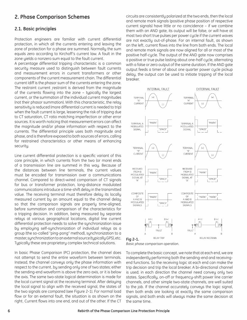
In basic Phase Comparison (PC) protection, the channel does not attempt to send the entire waveform between terminals. Instead, the channel conveys only the phase information with respect to the current, by sending only one of two states; either the sending-end waveform is above the zero axis, or it is below the axis. The same two-state logical determination is made for the local current signal at the receiving terminal. After delaying the local signal to align with the received signal, the states of the two signals are compared (see Figure 2-1). For normal load fl ow or for an external fault, the situation is as shown on the right. Current fl ows into one end, and out of the other. If the CT
circuits are consistently polarized at the two ends, then the local and remote mark signals (positive phase position of respective current signals) have little or no coincidence – if we combine them with an AND gate, its output will be false, or will have at most two short true pulses per power cycle if the current waves are not exactly out-of-phase. For an internal fault, as shown on the left, current fl ows into the line from both ends. The local and remote mark signals are now aligned for all or most of the positive half-cycle. The output of the AND gate now comprises a positive or true pulse lasting about one-half cycle, alternating with a false or zero output of the same duration. If the AND gate output feeds a timer of about one quarter power cycle pickup delay, the output can be used to initiate tripping of the local breaker.
Fig 2-1. Basic phase comparison operation.
To complete the basic concept, we note that at each end, we are independently performing both the sending-end and receiving-end functions. So the receiving logic at each end can make the trip decision and trip the local breaker. A bi-directional channel is used; in each direction the channel need convey only two states. Specifi cally, on-off or frequency-shift power line carrier channels, and other simple two-state channels, are well suited to the job. If the channel accurately conveys the logic signal, then both ends are looking at exactly the same comparison signals, and both ends will always make the same decision at the same time.
7Rebirth of the Phase Comparison Line Protection Principle
Note that the system, even if implemented digitally, does not call for synchronization of the individual relays. This is because the information exchanged is encoded via timing of the pulses related to the same “analog” or “continuous” time.
Note that the core trip decision may be as fast as 6 to 8 ms, and is generally under one cycle, plus channel delays and processing delays in the relays.
Let us go back to one of the key differentiators between the Current Differential and Phase Comparison principles. Current Differential uses both magnitude and phase information, and is therefore prone to errors in either of these two components. Phase Comparison, in turn, uses the phase information only in terms of timing a particular current polarity, and therefore is much less sensitive to magnitude errors. As a rule, Phase Comparison is a more secure principle except in cases where low signal magnitude makes the phase information less accurate (such as on series-compensated lines). Response to CT saturation of a segregated Phase Comparison is a good example of the philosophical difference between 87L and 87PC principles.
2.2. Practical three-phase implementations
So far, we have sidestepped a key point. The above description talked about comparing one current wave, but of course there are at least three currents at each end. If we want to compare the residual currents at the two ends for ground fault detection, we have four choices. The straightforward but expensive approach is to run three or four comparisons in parallel, with multiple channels. The comparison method is robust for each of the three phases and for the residual current. With these four comparisons, two or more will provide a fault indication for any particular fault type (phase to ground, phase to phase, two phase to ground, three-phase). This segregated Phase Comparison approach has been successfully used for decades on important transmission lines where the economics of the channel needs are not a drawback. More recently, the four comparisons have been encoded using a modem on a single data channel to reduce channel demand, although this approach is not compatible with power-line carrier channels.
For the broadest range of applications on lines with familiar types of power-line carrier, we need to develop a single current wave at each end, that can be compared in order to detect any type of fault. This is traditionally accomplished by deriving the sequence components of the currents at each end. The relay then recombines or mixes the sequence currents with predetermined weighting factors to yield a single composite comparison current wave whose phase position gives robust discrimination of all fault types.
The three phase currents are transformed to three sequence currents using the familiar symmetrical components defi nition (for the ABC phase rotation):
(2-1)
where
Analysis of how these currents behave during faults shows the following:
Relay designers carry out detailed evaluation of the behavior of the sequence current phasors during the various fault types, while considering diffi cult boundary conditions such as high-resistance fault currents and heavy load fl ow before the fault.
For now, we point out that negative sequence current has the unique property of being a robust indicator of nine out of the ten fault types, as well as being clearly different for load versus fault current conditions. Comparing the negative sequence current waves at the two ends gives excellent fault protection, unless we experience a three-phase fault.
The only current with which to compare for a three-phase fault is the positive sequence current. To overlay this comparison with the negative-sequence comparison using the same channel, we mix a small quantity of positive sequence current with the negative sequence current according to:
(2-2)
Where IC is the comparison current wave developed at each line terminal and K is the design or settable positive-sequence weighting factor. A typical value for K is about 0.2. The comparison is thus dominated by negative sequence current, with only enough positive sequence mixing to ensure tripping for all three-phase faults that produce no I2.
Note that expression (2-2) is a vectorial difference, which has an impact on the amount of current seen during various fault types. For example, the amount of current is lowered during single-line-to-ground faults in the phase used as a reference for calculating the symmetrical currents, but not in the two other phases.
Early analog solid-state PC relays developed sequence currents using electromagnetic fi lters based on iron-core reactors, capacitors, and resistors. These fi lters were acceptably accurate
⎥⎥⎥
⎦
⎤
⎢⎢⎢
⎣
⎡
⎥⎥⎥
⎦
⎤
⎢⎢⎢
⎣
⎡=
⎥⎥⎥
⎦
⎤
⎢⎢⎢
⎣
⎡
C
B
A
III
aaaa
III
2
2
2
1
0
11
111
31
01201∠=a
TYPE OF FAULTSEQUENCE COMPONENTS
POSITIVE NEGATIVE ZERO
Single-phase-to-ground YES YES YES
Phase-to-phase YES YES NO
Double-phase-to-ground YES YES YES
Three-phase YES NO NO
12 IKIIC ⋅−=
8 Rebirth of the Phase Comparison Line Protection Principle
in steady-state operation. However, transient conditions could drive the reactors into nonlinear operation, and there was no guarantee that the fi lters at the two ends of the line would behave correctly, or identically, for badly distorted waves. In particular, the highly distorted fault currents of series-compensated lines would cause these relays to malfunction, and utilities with these lines adopted other methods including the segregated Phase Comparison that had no sequence fi lters.
Modern microprocessor-based PC relays use mathematical fi ltering techniques that are not subject to the same misbehavior. The sequence-fi ltering calculations are linear and well behaved, whether the wave is sinusoidal or distorted. An important fact is that both ends can be made to have the same response. Thus, modern relays using mixed-sequence components can handle diffi cult applications, such as series capacitors in the line, that confused older design generations.
2.3. Control of comparison and tripping
Practical systems do not exchange square waves constantly. In some power-line carrier systems, monitoring requires that the channel not be actively relaying most of the time. When light-load currents are fl owing or the line is fl oating, there may be a net current infl ow to the zone from line charging, that is not a fault. To restrict comparison to potential fault situations, we add fault detector elements in both the transmitting and receiving logic.
A fault detector can be a disturbance detector (delta I), an overcurrent element or an overreaching distance element. The latter is typically provided at no or marginal cost in modern microprocessor relays, and if used, is set with enough reach that it never fails to pick up an internal fault. Severe overreach of such supervisory elements is not a problem.
A practical relay uses separate fault detectors for the transmitting and receiving logic. The low-set or long-reach fault detector that triggers transmission of “square waves” (FDL) is always set more sensitively than the high-set or shorter-reach trip-supervising fault detector at the receiving end (FDH). We must ensure that the tripping end can never make a decision to trip based on the absence of carrier if the sending-end fault detector fails to pick up. Note that, since there are actually two mirror-image logic systems making comparisons, we fi nd an FDL setting and an FDH setting in the relay at each end.
Overcurrent elements can almost always be coordinated so that FDH at terminal A never picks up without FDL at Terminal B for an internal line zone fault. Using overcurrent is much better than using distance elements, because it completely eliminates the use of voltage in the PC protection scheme. This makes PC fast, as well as immune to CVT transients or to potential blown fuses or CVT failures.
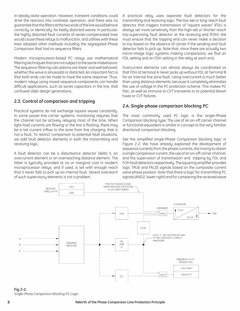
2.4. Single-phase comparison blocking PC
The most commonly used PC logic is the single-Phase Comparison blocking type. The use of an on-off carrier channel or functional equivalent is similar in concept to the very familiar directional comparison blocking.
See the simplifi ed single-Phase Comparison blocking logic in Figure 2-2. We have already explained the development of sequence currents from the phase currents, the mixing to obtain a single comparison current, the use of an on-off carrier channel, and the supervision of transmission and tripping by FDL and FDH fault detectors respectively. The squaring amplifi er provides logic TRUE and FALSE signals based on the composite current wave phase position. Note that there is logic for transmitting PC signals (AND2, lower right) and for comparing the received wave
Fig 2-2. Single-Phase Comparison Blocking PC Logic.
9Rebirth of the Phase Comparison Line Protection Principle
with the local wave (AND1, upper right). A delay line function delays the local square wave by the same amount of time that the carrier channel delays the received square wave, so we can treat the local and remote square waves as perfectly aligned for currents that are exactly in phase. The output of AND1 feeds a tripping timer, also called the coincidence timer. Note that the term “square wave” is used for simplicity and education. In general the wave is not symmetrical but should refl ect the positive and negative polarities of the current. Relay design solutions based on the term “square” (i.e. assuming or forcing the transmission to be symmetrical within the cycle), used to cause problems (on series-compensated lines for example).
Consider the behavior of this logic with the internal and external fault situations shown in Figure 2-1. Assume that the faults cause both FDL and FDH to pick up. The FDH input to AND1 will allow tripping at this terminal only if FDH is TRUE. The FDL input to AND2 enables the squaring amplifi er output to key the blocking transmitter ON and OFF according to the phase position of the composite wave. Note that, since the square wave input to AND2 is inverted, the transmitter is keyed ON (blocking state) when the composite current wave is negative and keyed OFF (blocking removed) when the current is positive.
Now consider what happens in the receiving logic at the other end. Figure 2-1 shows that, if the fault is external or if only load is fl owing, the positive half-cycles occur in alternating (rather than coincident) half-cycle time frames. When the local current is positive, the squaring amp and delay line are feeding a true or mark input to the bottom of the comparer, AND1. But at the same instant, the remote wave is negative and the blocking carrier is received. The blocking signal is fed into the inverter input of AND1, where it prevents the output of AND1 from running the 3-millisecond timer that leads to a trip decision. Thus, the remote end blocks tripping using the carrier signal whenever the local delay line is feeding a TRUE signal to the comparer.
For internal faults, the phase position of the remote square wave is reversed by roughly 180 degrees. In this case, when the local wave is positive, the carrier from the remote terminal is OFF. For an ideal fault, the conditions for AND1 are met during the entire positive half-cycle of over 8 ms. After just 3 ms, the logic issues a trip output. This comparison result is mirrored at both terminals.
An important feature of the blocking PC scheme is that transmitters at both (or all three) line terminals can transmit on the same frequency, as is true for blocking DC. Using a single carrier frequency conserves valuable carrier spectrum, especially with a three-terminal line. When the local transmitter sends the blocking signal, both the local and remote receivers respond to it . The logic of Figure 2-2 shows that, when the transmitter is keyed ON (when the local square wave is negative), the local comparer is blocked by the pickup of the local receiver. For an internal fault, both (or all) transmitters must go silent for the 3 ms coincidence time, at which point all terminals are able to trip.
As with DC blocking – if the blocking carrier channel isn’t able to send a blocking signal during a fault, the local pilot logic is not restrained from tripping. The important benefi t of this logic is apparent for an internal fault, which shorts line conductors and may attenuate or completely short out the blocking carrier signal; tripping can still take place with no loss of time. If the channel equipment has actually failed, this can lead to a false trip for an external fault. Thus, ON-OFF carrier should be tested often, preferably by an automatic check-back test that runs several times per day.
2.5. Trip time
The time to reach this decision depends on the phase position of the measurement currents at fault inception. For the logic shown and an ideal fault, the decision time ranges from 3 to about 12 ms. Add to these the channel delay time (also set as the local delay time), which can range from 4 ms to 12 ms depending on the carrier channel bandwidth. Also, add the current signal fi ltering and processing time, and the time for the trip output device to pick up. A relay contact output adds 2-4 ms unless a fast solid-state output is used. For a fast carrier channel, total trip times range from 1/2 cycle to 1 cycle depending on the fault inception angle. The upper end of this trip time range can be drastically reduced with dual-comparison logic described below.
Sections 4.3 and 6.8 below explain how the setting of the coincidence timer (typically about 3 ms) is determined, and how the timer is implemented in the most effective design.
Narrowband carrier sets that conserve spectrum and handle longer lines with greater attenuation, also unavoidably use selective fi lters that reject adjacent channel signals and the out-of-band corona noise. These receiver fi lters respond slowly to changes in the transmitted signal, and the output appears after a relatively long delay. This necessarily requires coordinating delays in the PC (or DC) logic, which slows down the pilot protection. For fast tripping, use wideband carrier sets or confi gurations. Ensure that the transmitted power can overcome coupling and channel losses with adequate margin at the receiver. Section 3 gives more guidance on this point.
2.6. Dual-phase comparison blocking PC logic
As we explained above, the actual trip time for single-Phase Comparison PC can vary, depending on the polarity and phase of the ac wave at fault inception. It is clear that the longer trip times could be reduced if the relay were able to compare phase relationships on both half-cycles instead of just one. It is also clear from the logic explanation, that this can’t be done with security using a single ON-OFF channel.
If the user is willing to upgrade the carrier channel to a frequency shift keying (FSK) system of a two-frequency or three-frequency type, the relay can implement more complex logic that compares both polarities in alternation. While the fastest trip times will be at best the same as with single-Phase Comparison PC, this enhancement cuts over 8 ms from the
10 Rebirth of the Phase Comparison Line Protection Principle
longest trip times, narrowing the variation of trip times to the 3-5 ms range. In making this comparison of trip times, we assume, of course, that the channel delay did not change when the ON-OFF carrier was exchanged for FSK. The potential user must check this point carefully when selecting the FSK carrier; looking at the class averages, FSK transmitters and receivers operate in narrower bands than blocking ON-OFF carriers, and have longer channel delays. Fast wideband FSK carriers are available with large frequency shifts at a cost of increased spectrum consumption and reduced tolerance of carrier-path attenuation (due to increased noise in the wide-open passband of the receiver).
An FSK carrier transmitter is constantly sending a signal – a guard or monitoring frequency – which shifts to another frequency (or choice of two other frequencies in a 3-frequency system) on command from the relay. Because of this, the transmitter at each end of the line must have its own assigned frequency slot, to which the remote receiver is set. If the line has 3 terminals, then 3 frequency slots are consumed, and each terminal has two receivers to hear each of the two other transmitters independently. In analyzing how the logic works, keep in mind that an internal fault can still short out the carrier signal, causing a loss of guard at the moment of fault inception. Also remember that in this case, the local receiver(s) will not change state in response to the local transmitter, as it hears only the companion remote transmitter.
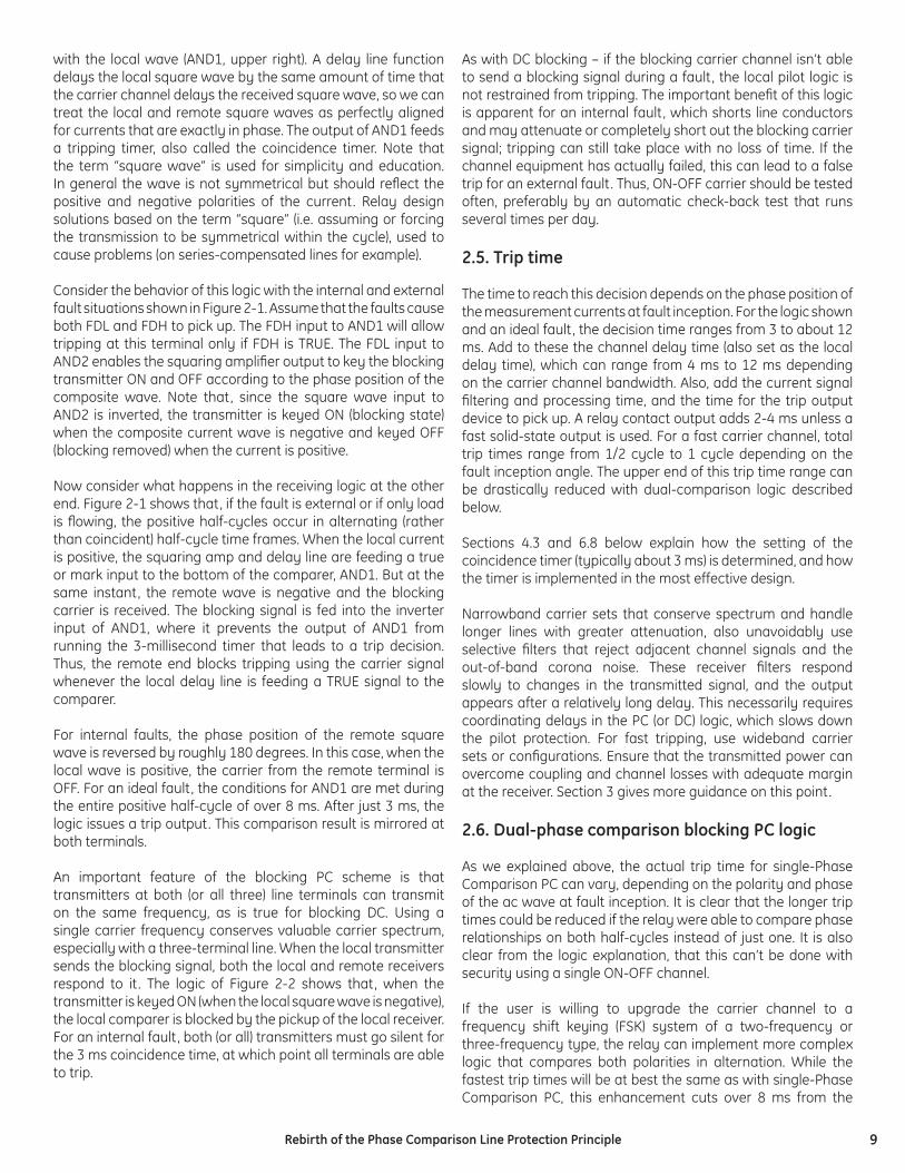
Figure 2-3 shows simplifi ed dual-Phase Comparison blocking PC scheme logic, used with a two-frequency FSK channel. Comparing this to Figure 2-2, note the use of both positive and negative squaring calculations, feeding the two independent comparers AND1 and AND2. For simplicity, the channel delay compensation is not shown, but is applied where the local squared wave enters each comparer gate (the squared signal
that shifts the local transmitter to high during the negative half cycle is not delayed). The local receiver has two outputs that alternate according to the remote current. In this logic, since the transmitter is sending at all times in any case, the FDL element is deleted and the channel is keyed constantly with phase information. The FDH overcurrent or overreaching distance element at the receiving end enables tripping.
For external faults, the channel signal alternations block one comparer and then the other in turn when the local input would enable tripping. For an internal fault, the received square wave aligns out of phase with the local squared wave, so that it does not block the comparer, and the coincidence time delay expires. If the internal fault kills the received carrier, blocking is removed from both gates and either local wave polarity can pick up its comparer gate and trip the terminal. For security and channel monitoring, tripping can only occur if the channel loss coincides with pickup of FDH, and is only allowed for 150 ms after pickup of FDH. For complete loss of carrier at other times, PC tripping is blocked. Sustained channel failure should be alarmed.
A popular variation of this logic is dual-Phase Comparison unblocking. It is a cross between blocking and tripping (next section) in that it operates in the blocking mode but the blocking signal is sent continuously as a guard signal during non-fault times. Unblocking logic uses a two-state FSK carrier. The squaring amp output is used to shift the carrier to the trip frequency, removing the block at the remote terminal if the waves are aligned. Unblocking logic can also trip if an internal fault shorts the carrier signal; tripping can occur if the carrier loss coincides with FDH pickup, and is limited to a 150 ms window after fault inception, as for the blocking logic. The scheme must include some means to stop the blocking signal from being transmitted from an open terminal in the event of a fault. For example, a breaker 52b auxiliary contact.
Fig 2-3. Dual-Phase Comparison Blocking PC Logic.
11Rebirth of the Phase Comparison Line Protection Principle
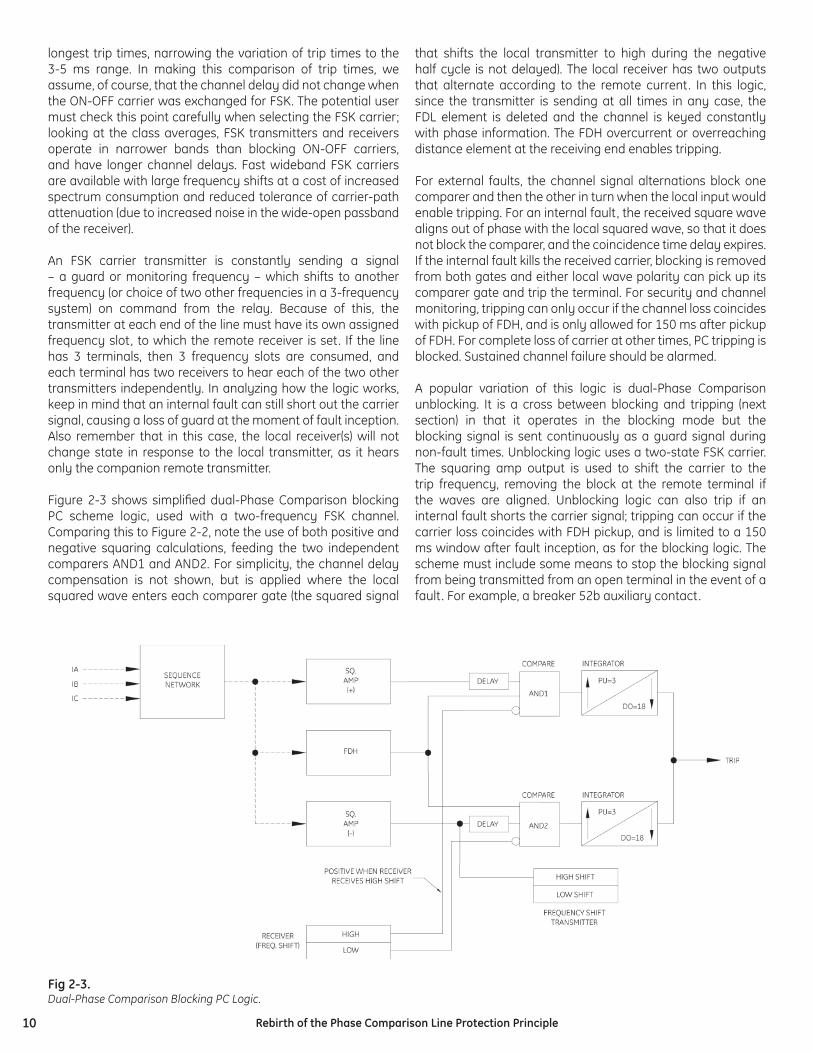
2.7. Dual-phase comparison tripping PC logic
Figure 2-4 shows the more elaborate logic of the dual-Phase Comparison tripping scheme. Compared with the dual-Phase Comparison blocking logic of the last section, this logic offers the better security, but requires a three-frequency channel. The center frequency of the three-frequency channel is not used for protection logic, but provides continuous monitoring of the channel integrity, important for security during non-fault times.
The fault detector FDH supervises tripping by either positive or negative comparisons. For the positive half-cycle, AND1 compares the alignment of the delayed local positive square wave (the delay buffer for the SQ. AMP (+) output as it feeds into AND1 is not shown) and the remote positive square wave as conveyed by the high-state detector output of the receiver. If the local and remote waves are aligned for over 3 ms, the integrator or comparer output picks up and tripping is initiated. Similarly, AND2 compares the alignment of the delayed local negative half-cycle square wave and the remote negative half-cycle wave as conveyed by the low-state detector output of the receiver.
The local transmitter sends a continuous guard signal on the center frequency for channel monitoring during non-fault times, and is keyed to high or low frequencies by the squaring amplifi er outputs only if the low-set fault detector FDL picks up. As with the other logic schemes, the local FDL should be set to always pick up for any internal or external fault that picks up the remote FDH. However, note the security bias of this tripping logic: the remote terminal cannot trip if the local FDL fails to pick up and the channel is not keyed. Gate AND3 ensures that the transmitter is never asked to send high and low frequencies at the same time; it cannot do this. The negative square wave takes priority and causes a low shift in the event, such that both are momentarily present.
3. Channel Requirements & Limitations
Depending on speed requirements and logic selection, 87PC is most often used with ON-OFF or frequency shift (FSK) carrier channels. Phase Comparison is desirable because it yields all its benefi ts, explained throughout this paper, using such ubiquitous, utility-owned, economical channels. 87PC also performs well on other channels, ones suited to binary state transmission: audio tone sets on leased analog telephone circuits or analog microwave, and digital data transfer sets operating on the same audio circuits or on dedicated fi bers.
87PC can work with contact transfer cards in T1/E1, SONET, digital microwave, or other multiplexed data communications WAN facilities in use at a growing number of utilities, as long as the channel can be confi gured such that the propagation delay is constant or within tight constraints (under 1 ms variation) in the face of switching or rerouting events. This communications fl exibility, along with outstanding protection abilities, makes Phase Comparison a natural choice for a standard pilot scheme, useable across the entire power system. The ability of Phase Comparison to work on a carrier channel is its major trump card over current differential protection, although it has other protection performance advantages that are explained throughout this paper.
Accordingly, the logic and processing algorithms are carefully arranged to handle the idiosyncrasies of carrier channels, along with those of other channel types. These logic and algorithm adaptations are explained in previous and following sections.
To begin, the Phase Comparison user (or any carrier-based pilot relay user) should begin with proper application analysis of the carrier channel itself. See references [1], [2], and [3] for important details. The application process comprises:
Fig 2-4. Dual-Phase Comparison Tripping PC Logic.
12 Rebirth of the Phase Comparison Line Protection Principle
1. Channel loss calculations from transmitter power level (typical +30 dbm or 10 watts) to received signal level.
a. Hybrid losses, as the transmitter is combined with other transmitters and receivers sharing the same tuning interface to the line. Add to this hybrid losses in db, at the remote (receiving) end.
b. Outbound local coupling losses based on tuner, CVT, and modal analysis of the coupling to the line (often on the center phase or an outer phase). Add to this the inbound coupling losses in db at the other end of the line.
c. Loss in db per unit length of line, based on line voltage and construction, and on the chosen frequency of operation.
d. Losses due to mode conversion at each transposition point.
e. Losses due to imperfect blocking of modes by line traps.
2. Channel noise calculations at the receiver.
a. Corona noise data in dbm based on line voltage and construction, as well as the chosen frequency of operation.
b. Corona noise during foul weather and icing conditions, as opposed to fair weather levels.
c. Noise power correction for the bandwidth of the receiver, as compared to the bandwidth of the instruments used to collect either the reference data, or actual measurements from a line in operation before applying the carrier.
d. Corona noise power is often in milliwatts and swamps any electronic circuit or thermal noise, which are ignored.
3. Calculation of signal to noise ratio (SNR) at the receiver detector
a. Ensure SNR of at least 10 db to 20 db for the worst noise conditions.
b. Ensure that transmitter power is adequate to yield this SNR. Increase power (use an amplifi er), improve hybrid connection architecture, or upgrade line-coupling equipment to raise signal level. If signal is very high, receiver must have gain attenuation control and signal level metering.
4. Other application considerations
a. Select modern transmitter-receiver sets with frequency synthesis, selectable bandwidths, 3-frequency or 4-frequency operation to combine transfer trip with pilot protection, and serial or Ethernet data communications ports for integration of the carrier set with substation control systems and remote monitoring.
b. Check the bandwidth of the carrier channel for its effect on channel delay and its impact on tripping speed. It is
also important to have an initial delay estimate within ½ cycle of the exact value to avoid aliasing errors when adjusting the relay logic channel delay using the load testing methods explained in the following section.
c. Check that the channel logic bundled in the receiver by the manufacturer, does not confl ict with duplicate or alternate logic in the relay. Turn it off, or order equipment without unneeded logic.
d. Use channel monitoring including guard loss (FSK), automatic checkback testing (ON-OFF or ASK), reduced-power margin testing, and out-of-band noise detection (correction of noise alarm setting for noise monitor bandwidth, versus bandwidth of reference or fi eld data).
e. Ensure that there is a maintenance program for line coupling equipment, especially outdoor equipment such as coax cable, line tuners, drain coils at the base of the CVT, and protective gaps on CVT and line tuners, that often collect spiders’ webs (the contaminated gap fl ashes for mild voltage transients and shorts the carrier signal, producing carrier holes).
f. Avoid the frequencies of licensed radio services operating near the line, that use a carrier band of 30 kHz to 535 kHz.
g. Integrate with spectrum management with respect to the interconnected network; frequency use typically not repeated for at least two line sections away, or mitigate with better line trap confi guration.
h. Check for compatibility of telemetry or voice facilities operating on carrier channels during quiescent times.
i. Ensure there is a program for reviewing analog carrier channel input oscillograms (remotely retrievable COMTRADE fi les) provided by the latest microprocessor relays (explained in the next section), to check for holes in, or deterioration of, received carrier signals, and for dispatching maintenance before experiencing relaying problems.
j. When employing ON-OFF carriers at three-line terminals all sharing the same frequency for 3-terminal single comparison blocking, ensure that the transmit frequencies are offset slightly (about ± 100 Hz) to avoid the risk of zero-beat cancellation during any external fault seen by two or three terminals.
Note that in Section 4.4 below, the text explains to the user how the logic and timing of the Phase Comparison can be adjusted to minimize exposure to tripping problems due to intense positive corona discharges.
While applying these methods can only help add to the security margin for any installation, the authors emphasize that it is critical to design the carrier system with an adequate signal-to-noise ratio under the worst conditions, as explained both above and in the referenced carrier application guides.
If this is done right, the corona noise concerns of Section 4.3 won’t matter. The advice in 4.4 below has been helpful for ensuring tripping dependability in overseas applications where carrier channel performance was marginal.
13Rebirth of the Phase Comparison Line Protection Principle
4. Application of Phase Comparison
4.1. General principles
Setting a phase comparison relay is simple. In general, only a handful of settings is required:
Scheme type(blocking/tripping, single/dual comparison).
This selection is typically driven by system conditions such as weak infeed, channel availability and characteristics, and historical experience within a given utility. Typically the design group makes this selection “once and for all” for a given utility, voltage level, etc.
Operating current (phase segregated, zero- or negative-sequence, K-value, coincidence timer/angle) and fault detectors (FDL, FDH)
This requires simple short-circuit calculations, and following simple setting rules, lessening the work requirements for the project group. These settings have plenty of margin and are robust in the face of system evolution, so fewer coordination studies are needed over time. Some of these can be standardized for the entire range of system applications at a utility.
Channel settings (delay, pulse asymmetry).
This is done on a per installation basis using channel measurements and experimentation, and is thus part of commissioning. Modern digital relays simplify this task greatly by providing excellent channel monitoring tools.
Application of Phase Comparison not be concerned with many obstacles applicable to distance or digital current differential relays, but needs to focus on the following basics, and advanced protection concepts, as applicable:
• Settings fault detectors (Section 4.2).
• Setting of the coincidence timer (Section 4.3)
• Selecting phase reference (Section 4.4)
• Channel delay setting (Section 4.5)
• Weak-infeed conditions (Section 4.6)
• Three-terminal lines (Section 4.7)
• Two-breaker terminals (Section 4.8)
• Long lines and cables (Section 4.9)
• Single-pole tripping (Section 4.10)
• Series-compensated lines (Section 4.11)
4.2. Coordinating fault detector settings
The fault detectors must satisfy the following setting rules:
a. FDH must pick up at all line terminals for all types of faults and locations and target fault resistance for SLG faults.
b. The phase difference in the operating current between any two terminals during all internal fault situations must be less than the tripping threshold of 90 degrees theoretically, and about 115 degrees in practice.
c. For blocking schemes, the FDL at the local relay must be set low enough to pick up on all reverse faults that activate the FDH level at the remote terminal.
d. Neither FDL nor FDH should be picked up under load conditions.
The above rules are straightforward for phase-segregated applications.
Consider next the negative-sequence operating mode. Here typical setting rules are:
(4-1a)
(4-1b)
The 10% margin in equation (4-1a) with respect to load requirement (D) is acceptable, as sporadic pickup of the scheme is allowed on load, swing or switching events. The charging current requirement in equation (4-1b) can be eliminated if a given relay compensates for it (see Section 4.6).
On long heavily loaded lines, the FDH value of equation (4-1) may have diffi culty meeting the dependability condition (A). If this is the case, advanced starting such as impedance or disturbance detection (delta I) can be used in parallel with regular overcurrent starting. This inconvenience can be easily overcome compared with coordination problems encountered for distance functions on long, three-terminal or heavily loaded lines.
4.3. Coincidence timer setting
For the ideal fault cases of Figure 2-1, the “square waves” are either in perfect alignment or in perfect opposition, suggesting a coincidence timer setting of 8.33 ms for a 60 Hz power system. However, real faults are never so perfect, and the “square waves” do not have ideal zero degree or 180 degree relationships. Among the factors that change the phase relationship are:
1. Through-load currents fl owing during the fault. 2. Load combined with nonzero fault resistance.
3. CT saturation, which narrows the positive and/or negative current wave pulses and shifts the phase position of zero crossings.
LOADPKP IKFDL ⋅⋅= 1.1
PKPCHARGEPKP FDLIFDH ⋅+⋅=34
83
14 Rebirth of the Phase Comparison Line Protection Principle
4. Line capacitance charging current, which produces a net infl ow from the two or more terminals.
5. Faulty adjustment of the local delay timer, or unnoticed changes in channel delay.
6. For a solid internal fault at a time of load fl ow, the source angle differences between the buses will lead to phase angle difference between the currents each end contributes to the fault (this will not happen during external faults, and does not impact security).
7. Asymmetrical pickup and dropout times for the carrier receiver (pulse asymmetry).
Exhaustive analysis of real-world fault cases has shown that a coincidence timer setting of 3 to 4 ms for a 60 Hz system provides good security against false tripping in the face of all the infl uences we just listed, while tripping reliably for all internal faults. 3 ms corresponds to a minimum blocking angle zone of about 65 degrees. See Section 6.8 below for an explanation of how to implement the coincidence timer function.
4.4 Corona Effect – Selecting reference and shifting the operating current
Power lines generate high-frequency noise due to the corona effect. If the carrier installation has been properly designed and maintained as explained in Section 3, the receiver signal-to-noise ratio will be adequate for reliable tripping in the face of the worst corona noise. If the carrier channel is quite marginal, there is a danger that the corona noise may be received by the carrier equipment as a valid signal. This in turn may result in worsened dependability when using blocking schemes. For users who cannot correct the basic carrier system shortfall, it is benefi cial to shift the “space” periods away from the corona-induced noise. This can be done when using single-comparison schemes because of the asymmetry of the corona effect. The following setting methods can only help improve the margin in any installation, but can be ignored without risk if the channel SNR is as robust as it should be.
The power conductor (round) and ground (fl at plane) creates an asymmetrical capacitor, making the positive corona (potential of the conductor is positive with respect to ground) much worse than the negative corona. As a result the “space” periods should be shifted away from the positive peaks of the voltage towards the negative peaks and small voltage values, at least for faults that do not involve the conductor on which the carrier is installed. In the latter case, we trust that the fault will depress the voltage, alleviate the corona effect, and reduce the danger of creating a ghost mark period within the actual space interval.
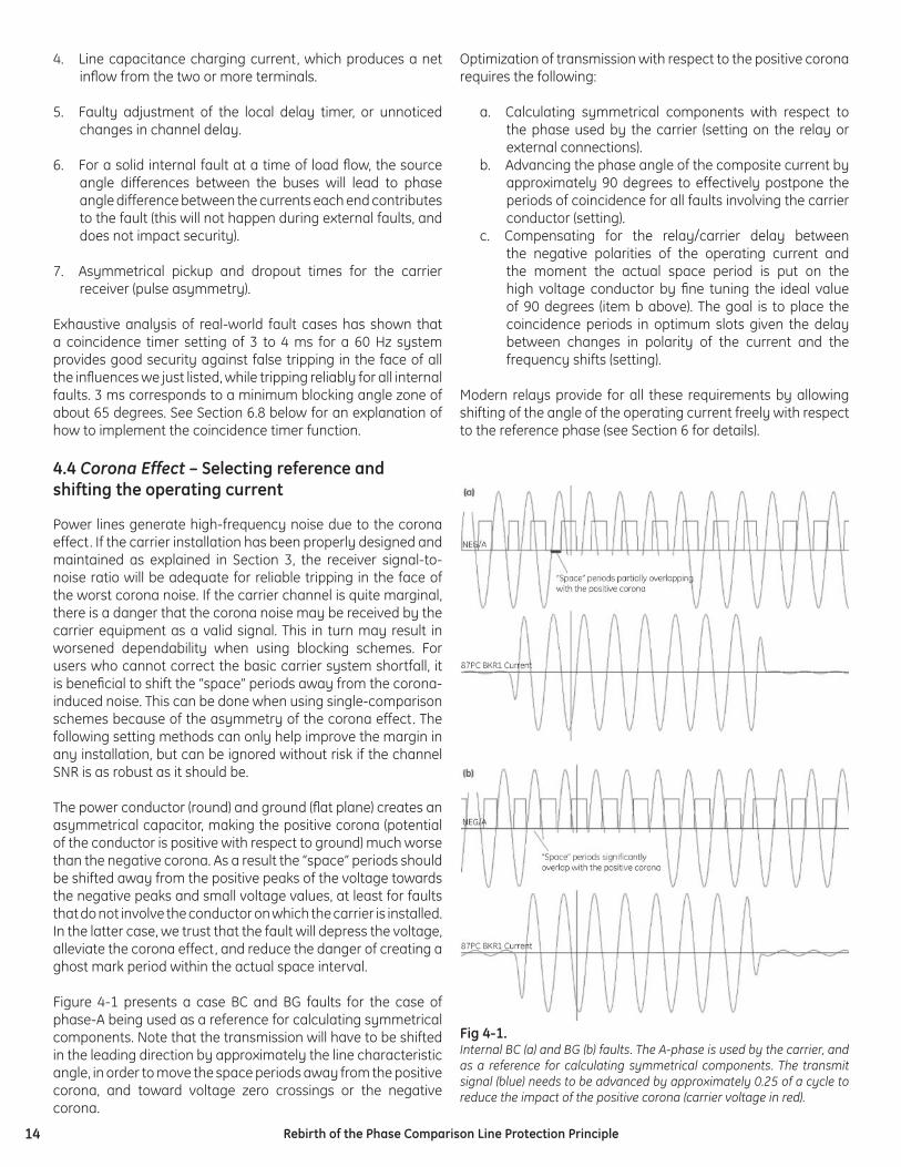
Figure 4-1 presents a case BC and BG faults for the case of phase-A being used as a reference for calculating symmetrical components. Note that the transmission will have to be shifted in the leading direction by approximately the line characteristic angle, in order to move the space periods away from the positive corona, and toward voltage zero crossings or the negative corona.
Optimization of transmission with respect to the positive corona requires the following:
a. Calculating symmetrical components with respect to the phase used by the carrier (setting on the relay or external connections).
b. Advancing the phase angle of the composite current by approximately 90 degrees to effectively postpone the periods of coincidence for all faults involving the carrier conductor (setting).
c. Compensating for the relay/carrier delay between the negative polarities of the operating current and the moment the actual space period is put on the high voltage conductor by fi ne tuning the ideal value of 90 degrees (item b above). The goal is to place the coincidence periods in optimum slots given the delay between changes in polarity of the current and the frequency shifts (setting).
Modern relays provide for all these requirements by allowing shifting of the angle of the operating current freely with respect to the reference phase (see Section 6 for details).
Fig 4-1. Internal BC (a) and BG (b) faults. The A-phase is used by the carrier, and as a reference for calculating symmetrical components. The transmit signal (blue) needs to be advanced by approximately 0.25 of a cycle to reduce the impact of the positive corona (carrier voltage in red).
15Rebirth of the Phase Comparison Line Protection Principle
4.5. Channel settings
It takes a fi nite time to transport the phase pulses between terminals on the line. Each receiving relay must delay its local pulses, and potentially remote pulses from a faster channel, in order to align the information before measuring the coincidence time for the trip/no-trip decision. Channel delay is therefore one of the crucial relay settings. Practical values of channel delay could reach or exceed an equivalent of 90 degrees making it necessary to measure and compensate for it .
Modern relays allow explicit measurement of the channel delay during controlled conditions such as commissioning. The most accurate way is to measure the delay using either GPS-synchronized current injection, or by observing relaying square wave coincidence alignment for a through load condition for natural synchronization. The latter requires forcing the relays into keying by temporarily lowering the FDL settings, or by overriding the actual key condition from other more convenient fl ags. Care must be taken when tuning the delay setting based on the natural load on long lines; charging current will play a role there. A choice can be made, however, to align the two terminals taking into account the typical load and the actual line-charging current.
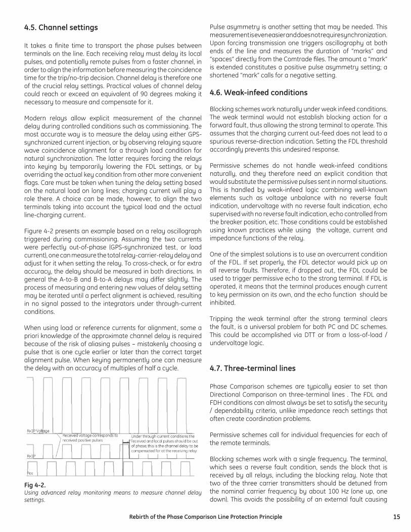
Figure 4-2 presents an example based on a relay oscillograph triggered during commissioning. Assuming the two currents were perfectly out-of-phase (GPS-synchronized test, or load current), one can measure the total relay-carrier-relay delay and adjust for it when setting the relay. To cross-check, or for extra accuracy, the delay should be measured in both directions. In general the A-to-B and B-to-A delays may differ slightly. The process of measuring and entering new values of delay setting may be iterated until a perfect alignment is achieved, resulting in no signal passed to the integrators under through-current conditions.
When using load or reference currents for alignment, some a priori knowledge of the approximate channel delay is required because of the risk of aliasing pulses – mistakenly choosing a pulse that is one cycle earlier or later than the correct target alignment pulse. When keying permanently one can measure the delay with an accuracy of multiples of half a cycle.
Pulse asymmetry is another setting that may be needed. This measurement is even easier and does not require synchronization. Upon forcing transmission one triggers oscillography at both ends of the line and measures the duration of “marks” and “spaces” directly from the Comtrade fi les. The amount a “mark” is extended constitutes a positive pulse asymmetry setting; a shortened “mark” calls for a negative setting.
4.6. Weak-infeed conditions
Blocking schemes work naturally under weak infeed conditions. The weak terminal would not establish blocking action for a forward fault, thus allowing the strong terminal to operate. This assumes that the charging current out-feed does not lead to a spurious reverse-direction indication. Setting the FDL threshold accordingly prevents this undesired response.
Permissive schemes do not handle weak-infeed conditions naturally, and they therefore need an explicit condition that would substitute the permissive pulses sent in normal situations. This is handled by weak-infeed logic combining well-known elements such as voltage unbalance with no reverse fault indication, undervoltage with no reverse fault indication, echo supervised with no reverse fault indication, echo controlled from the breaker position, etc. Those conditions could be established using known practices while using the voltage, current and impedance functions of the relay.
One of the simplest solutions is to use an overcurrent condition of the FDL. If set properly, the FDL detector would pick up on all reverse faults. Therefore, if dropped out, the FDL could be used to trigger permissive echo to the strong terminal. If FDL is operated, it means that the terminal produces enough current to key permission on its own, and the echo function should be inhibited.
Tripping the weak terminal after the strong terminal clears the fault, is a universal problem for both PC and DC schemes. This could be accomplished via DTT or from a loss-of-load / undervoltage logic.
4.7. Three-terminal lines
Phase Comparison schemes are typically easier to set than Directional Comparison on three-terminal lines . The FDL and FDH conditions can almost always be set to satisfy the security / dependability criteria, unlike impedance reach settings that often create coordination problems.
Permissive schemes call for individual frequencies for each of the remote terminals.
Blocking schemes work with a single frequency. The terminal, which sees a reverse fault condition, sends the block that is received by all relays, including the blocking relay. Note that two of the three carrier transmitters should be detuned from the nominal carrier frequency by about 100 Hz (one up, one down). This avoids the possibility of an external fault causing
Fig 4-2. Using advanced relay monitoring means to measure channel delay settings.
16 Rebirth of the Phase Comparison Line Protection Principle
two or more transmitters to zero-beat out-of-phase and cancel the blocking signal at some receivers.
4.8. Two-breaker terminals – through currents and CT saturation
Past practice with respect to protecting two-breaker line terminals (breaker-and-a-half or ring-bus) is to sum up the two currents externally, and feed a single-breaker line relay with the total current fl owing into the protected line.
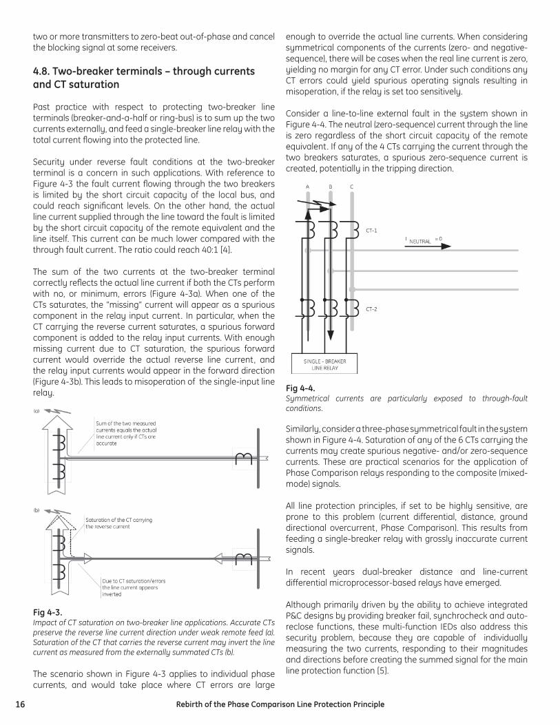
Security under reverse fault conditions at the two-breaker terminal is a concern in such applications. With reference to Figure 4-3 the fault current fl owing through the two breakers is limited by the short circuit capacity of the local bus, and could reach signifi cant levels. On the other hand, the actual line current supplied through the line toward the fault is limited by the short circuit capacity of the remote equivalent and the line itself. This current can be much lower compared with the through fault current. The ratio could reach 40:1 [4].
The sum of the two currents at the two-breaker terminal correctly refl ects the actual line current if both the CTs perform with no, or minimum, errors (Figure 4-3a). When one of the CTs saturates, the “missing” current will appear as a spurious component in the relay input current. In particular, when the CT carrying the reverse current saturates, a spurious forward component is added to the relay input currents. With enough missing current due to CT saturation, the spurious forward current would override the actual reverse line current, and the relay input currents would appear in the forward direction (Figure 4-3b). This leads to misoperation of the single-input line relay.
Fig 4-3.Impact of CT saturation on two-breaker line applications. Accurate CTs preserve the reverse line current direction under weak remote feed (a). Saturation of the CT that carries the reverse current may invert the line current as measured from the externally summated CTs (b). The scenario shown in Figure 4-3 applies to individual phase currents, and would take place where CT errors are large
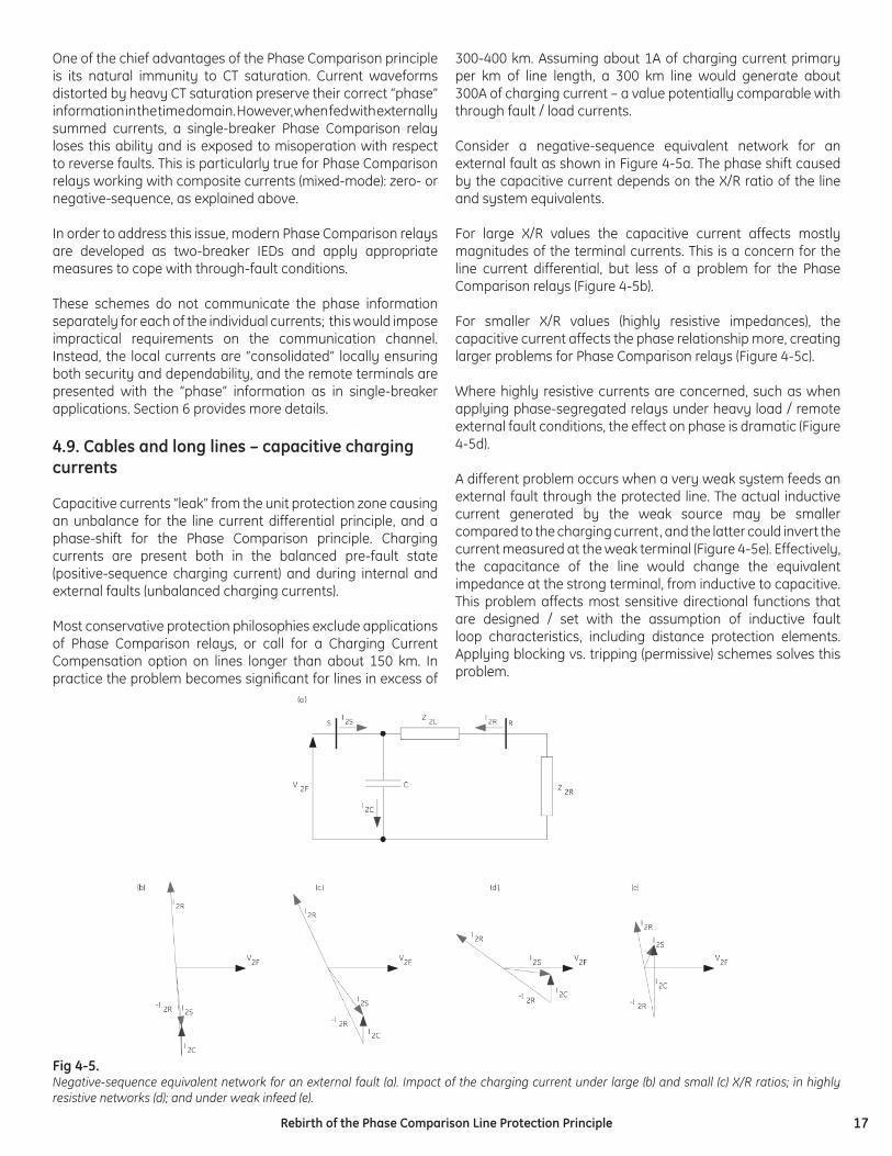
enough to override the actual line currents. When considering symmetrical components of the currents (zero- and negative-sequence), there will be cases when the real line current is zero, yielding no margin for any CT error. Under such conditions any CT errors could yield spurious operating signals resulting in misoperation, if the relay is set too sensitively.
Consider a line-to-line external fault in the system shown in Figure 4-4. The neutral (zero-sequence) current through the line is zero regardless of the short circuit capacity of the remote equivalent. If any of the 4 CTs carrying the current through the two breakers saturates, a spurious zero-sequence current is created, potentially in the tripping direction.
Fig 4-4. Symmetrical currents are particularly exposed to through-fault conditions.
Similarly, consider a three-phase symmetrical fault in the system shown in Figure 4-4. Saturation of any of the 6 CTs carrying the currents may create spurious negative- and/or zero-sequence currents. These are practical scenarios for the application of Phase Comparison relays responding to the composite (mixed-mode) signals.
All line protection principles, if set to be highly sensitive, are prone to this problem (current differential, distance, ground directional overcurrent, Phase Comparison). This results from feeding a single-breaker relay with grossly inaccurate current signals.
In recent years dual-breaker distance and line-current differential microprocessor-based relays have emerged.
Although primarily driven by the ability to achieve integrated P&C designs by providing breaker fail, synchrocheck and auto-reclose functions, these multi-function IEDs also address this security problem, because they are capable of individually measuring the two currents, responding to their magnitudes and directions before creating the summed signal for the main line protection function [5].
17Rebirth of the Phase Comparison Line Protection Principle
One of the chief advantages of the Phase Comparison principle is its natural immunity to CT saturation. Current waveforms distorted by heavy CT saturation preserve their correct “phase” information in the time domain. However, when fed with externally summed currents, a single-breaker Phase Comparison relay loses this ability and is exposed to misoperation with respect to reverse faults. This is particularly true for Phase Comparison relays working with composite currents (mixed-mode): zero- or negative-sequence, as explained above.
In order to address this issue, modern Phase Comparison relays are developed as two-breaker IEDs and apply appropriate measures to cope with through-fault conditions.
These schemes do not communicate the phase information separately for each of the individual currents; this would impose impractical requirements on the communication channel. Instead, the local currents are “consolidated” locally ensuring both security and dependability, and the remote terminals are presented with the “phase” information as in single-breaker applications. Section 6 provides more details.
4.9. Cables and long lines – capacitive charging currents
Capacitive currents “leak” from the unit protection zone causing an unbalance for the line current differential principle, and a phase-shift for the Phase Comparison principle. Charging currents are present both in the balanced pre-fault state (positive-sequence charging current) and during internal and external faults (unbalanced charging currents).
Most conservative protection philosophies exclude applications of Phase Comparison relays, or call for a Charging Current Compensation option on lines longer than about 150 km. In practice the problem becomes signifi cant for lines in excess of
300-400 km. Assuming about 1A of charging current primary per km of line length, a 300 km line would generate about 300A of charging current – a value potentially comparable with through fault / load currents.
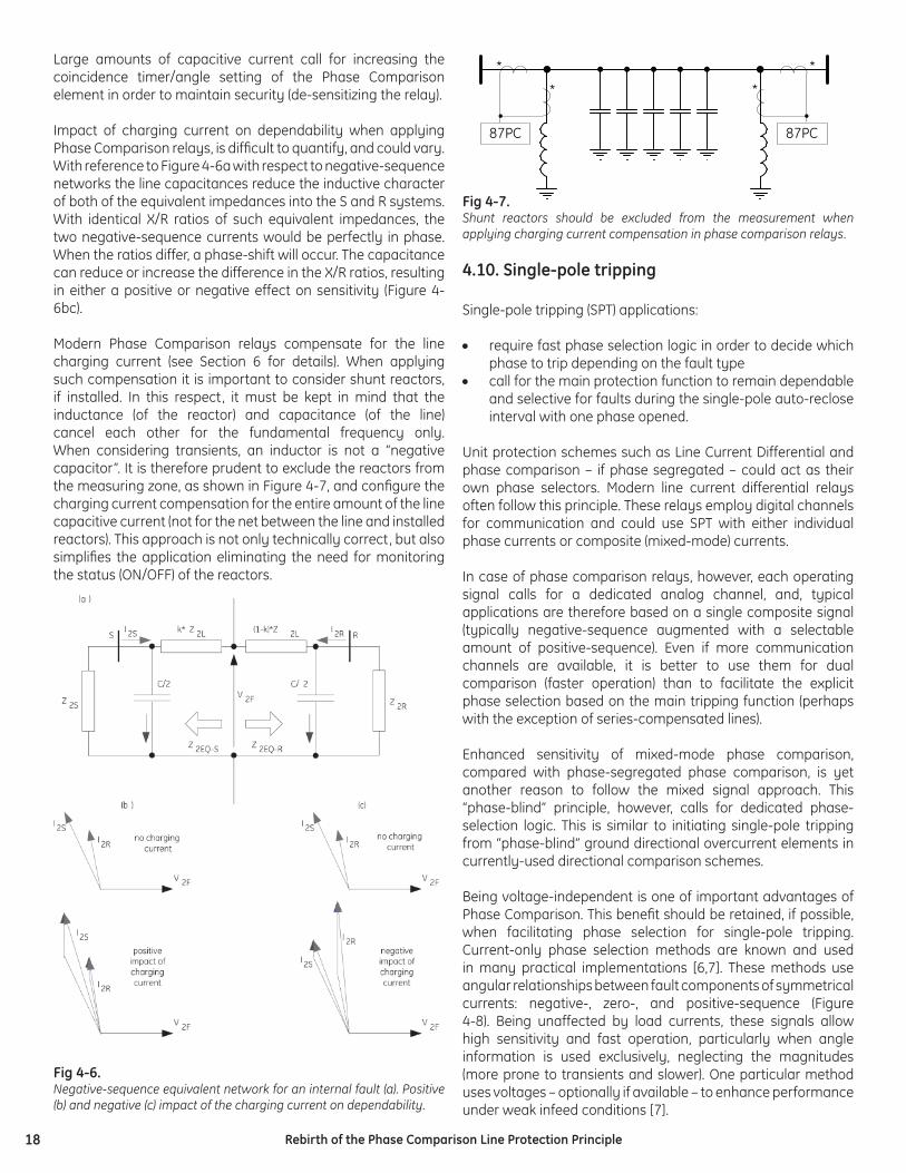
Consider a negative-sequence equivalent network for an external fault as shown in Figure 4-5a. The phase shift caused by the capacitive current depends on the X/R ratio of the line and system equivalents.
For large X/R values the capacitive current affects mostly magnitudes of the terminal currents. This is a concern for the line current differential, but less of a problem for the Phase Comparison relays (Figure 4-5b).
For smaller X/R values (highly resistive impedances), the capacitive current affects the phase relationship more, creating larger problems for Phase Comparison relays (Figure 4-5c).
Where highly resistive currents are concerned, such as when applying phase-segregated relays under heavy load / remote external fault conditions, the effect on phase is dramatic (Figure 4-5d).
A different problem occurs when a very weak system feeds an external fault through the protected line. The actual inductive current generated by the weak source may be smaller compared to the charging current, and the latter could invert the current measured at the weak terminal (Figure 4-5e). Effectively, the capacitance of the line would change the equivalent impedance at the strong terminal, from inductive to capacitive. This problem affects most sensitive directional functions that are designed / set with the assumption of inductive fault loop characteristics, including distance protection elements. Applying blocking vs. tripping (permissive) schemes solves this problem.
Fig 4-5. Negative-sequence equivalent network for an external fault (a). Impact of the charging current under large (b) and small (c) X/R ratios; in highly resistive networks (d); and under weak infeed (e).
18 Rebirth of the Phase Comparison Line Protection Principle
Large amounts of capacitive current call for increasing the coincidence timer/angle setting of the Phase Comparison element in order to maintain security (de-sensitizing the relay).
Impact of charging current on dependability when applying Phase Comparison relays, is diffi cult to quantify, and could vary. With reference to Figure 4-6a with respect to negative-sequence networks the line capacitances reduce the inductive character of both of the equivalent impedances into the S and R systems. With identical X/R ratios of such equivalent impedances, the two negative-sequence currents would be perfectly in phase. When the ratios differ, a phase-shift will occur. The capacitance can reduce or increase the difference in the X/R ratios, resulting in either a positive or negative effect on sensitivity (Figure 4-6bc).
Modern Phase Comparison relays compensate for the line charging current (see Section 6 for details). When applying such compensation it is important to consider shunt reactors, if installed. In this respect, it must be kept in mind that the inductance (of the reactor) and capacitance (of the line) cancel each other for the fundamental frequency only. When considering transients, an inductor is not a “negative capacitor”. It is therefore prudent to exclude the reactors from the measuring zone, as shown in Figure 4-7, and confi gure the charging current compensation for the entire amount of the line capacitive current (not for the net between the line and installed reactors). This approach is not only technically correct, but also simplifi es the application eliminating the need for monitoring the status (ON/OFF) of the reactors.
Fig 4-6. Negative-sequence equivalent network for an internal fault (a). Positive (b) and negative (c) impact of the charging current on dependability.
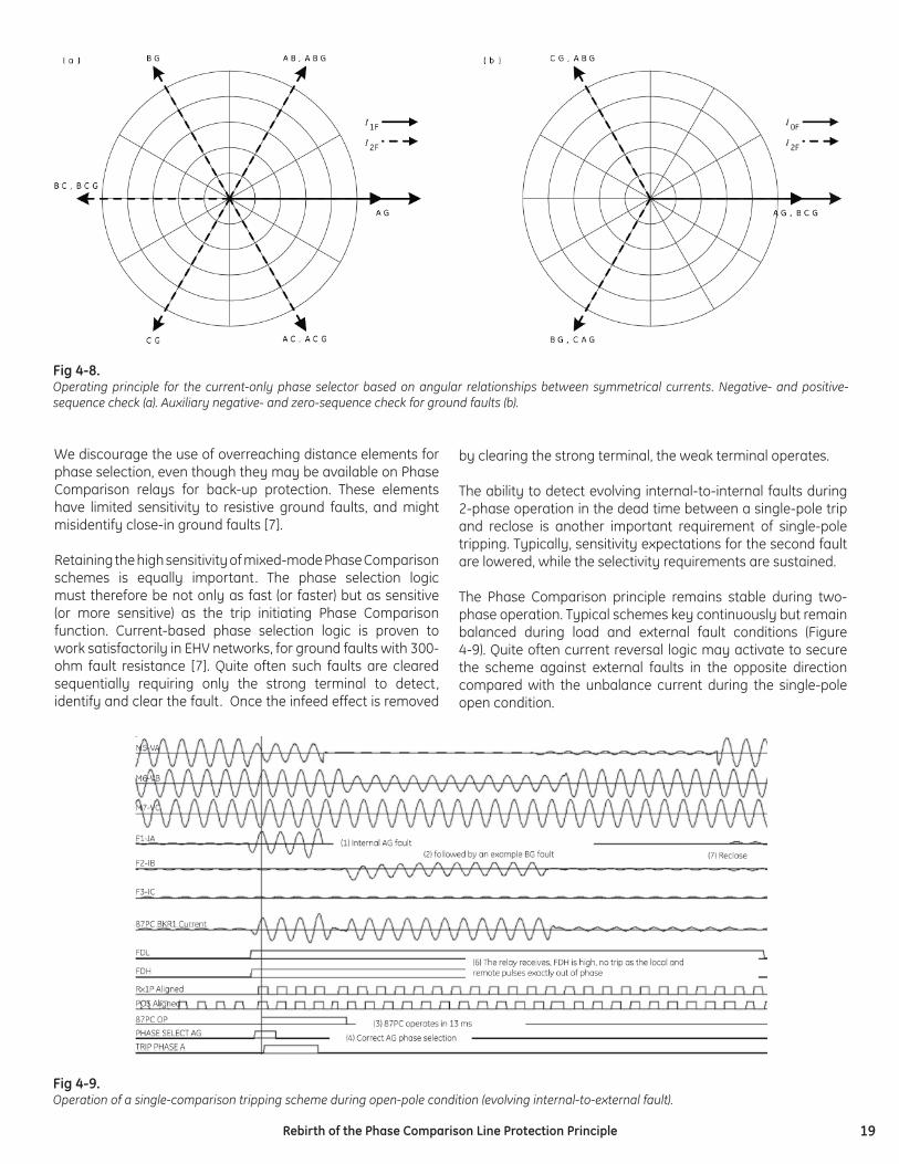
Fig 4-7. Shunt reactors should be excluded from the measurement when applying charging current compensation in phase comparison relays.
4.10. Single-pole tripping
Single-pole tripping (SPT) applications:
• require fast phase selection logic in order to decide which phase to trip depending on the fault type
• call for the main protection function to remain dependable and selective for faults during the single-pole auto-reclose interval with one phase opened.
Unit protection schemes such as Line Current Differential and phase comparison – if phase segregated – could act as their own phase selectors. Modern line current differential relays often follow this principle. These relays employ digital channels for communication and could use SPT with either individual phase currents or composite (mixed-mode) currents.
In case of phase comparison relays, however, each operating signal calls for a dedicated analog channel, and, typical applications are therefore based on a single composite signal (typically negative-sequence augmented with a selectable amount of positive-sequence). Even if more communication channels are available, it is better to use them for dual comparison (faster operation) than to facilitate the explicit phase selection based on the main tripping function (perhaps with the exception of series-compensated lines).
Enhanced sensitivity of mixed-mode phase comparison, compared with phase-segregated phase comparison, is yet another reason to follow the mixed signal approach. This “phase-blind” principle, however, calls for dedicated phase-selection logic. This is similar to initiating single-pole tripping from “phase-blind” ground directional overcurrent elements in currently-used directional comparison schemes.
Being voltage-independent is one of important advantages of Phase Comparison. This benefi t should be retained, if possible, when facilitating phase selection for single-pole tripping. Current-only phase selection methods are known and used in many practical implementations [6,7]. These methods use angular relationships between fault components of symmetrical currents: negative-, zero-, and positive-sequence (Figure 4-8). Being unaffected by load currents, these signals allow high sensitivity and fast operation, particularly when angle information is used exclusively, neglecting the magnitudes (more prone to transients and slower). One particular method uses voltages – optionally if available – to enhance performance under weak infeed conditions [7].
*
*
87PC
*
*
87PC
19Rebirth of the Phase Comparison Line Protection Principle
We discourage the use of overreaching distance elements for phase selection, even though they may be available on Phase Comparison relays for back-up protection. These elements have limited sensitivity to resistive ground faults, and might misidentify close-in ground faults [7].
Retaining the high sensitivity of mixed-mode Phase Comparison schemes is equally important. The phase selection logic must therefore be not only as fast (or faster) but as sensitive (or more sensitive) as the trip initiating Phase Comparison function. Current-based phase selection logic is proven to work satisfactorily in EHV networks, for ground faults with 300-ohm fault resistance [7]. Quite often such faults are cleared sequentially requiring only the strong terminal to detect, identify and clear the fault. Once the infeed effect is removed
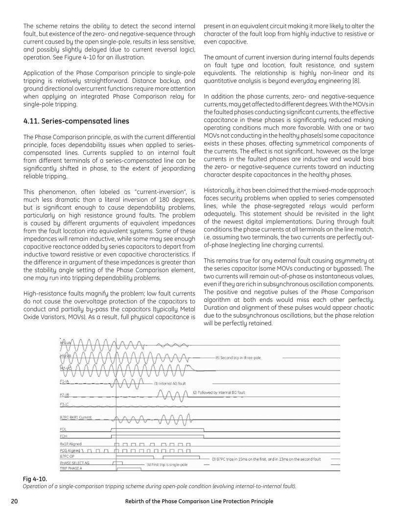
Fig 4-9. Operation of a single-comparison tripping scheme during open-pole condition (evolving internal-to-external fault).
by clearing the strong terminal, the weak terminal operates.
The ability to detect evolving internal-to-internal faults during 2-phase operation in the dead time between a single-pole trip and reclose is another important requirement of single-pole tripping. Typically, sensitivity expectations for the second fault are lowered, while the selectivity requirements are sustained.
The Phase Comparison principle remains stable during two-phase operation. Typical schemes key continuously but remain balanced during load and external fault conditions (Figure 4-9). Quite often current reversal logic may activate to secure the scheme against external faults in the opposite direction compared with the unbalance current during the single-pole open condition.
Fig 4-8. Operating principle for the current-only phase selector based on angular relationships between symmetrical currents. Negative- and positive-sequence check (a). Auxiliary negative- and zero-sequence check for ground faults (b).
20 Rebirth of the Phase Comparison Line Protection Principle
The scheme retains the ability to detect the second internal fault, but existence of the zero- and negative-sequence through current caused by the open single-pole, results in less sensitive, and possibly slightly delayed (due to current reversal logic), operation. See Figure 4-10 for an illustration.
Application of the Phase Comparison principle to single-pole tripping is relatively straightforward. Distance backup, and ground directional overcurrent functions require more attention when applying an integrated Phase Comparison relay for single-pole tripping.
4.11. Series-compensated lines
The Phase Comparison principle, as with the current differential principle, faces dependability issues when applied to series-compensated lines. Currents supplied to an internal fault from different terminals of a series-compensated line can be signifi cantly shifted in phase, to the extent of jeopardizing reliable tripping.
This phenomenon, often labeled as “current-inversion”, is much less dramatic than a literal inversion of 180 degrees, but is signifi cant enough to cause dependability problems, particularly on high resistance ground faults. The problem is caused by different arguments of equivalent impedances from the fault location into equivalent systems. Some of these impedances will remain inductive, while some may see enough capacitive reactance added by series capacitors to depart from inductive toward resistive or even capacitive characteristics. If the difference in argument of these impedances is greater than the stability angle setting of the Phase Comparison element, one may run into tripping dependability problems.
High-resistance faults magnify the problem; low fault currents do not cause the overvoltage protection of the capacitors to conduct and partially by-pass the capacitors (typically Metal Oxide Varistors, MOVs). As a result, full physical capacitance is
present in an equivalent circuit making it more likely to alter the character of the fault loop from highly inductive to resistive or even capacitive.
The amount of current inversion during internal faults depends on fault type and location, fault resistance, and system equivalents. The relationship is highly non-linear and its quantitative analysis is beyond everyday engineering [8].
In addition the phase currents, zero- and negative-sequence currents, may get affected to different degrees. With the MOVs in the faulted phases conducting signifi cant currents, the effective capacitance in these phases is signifi cantly reduced making operating conditions much more favorable. With one or two MOVs not conducting in the healthy phase(s) some capacitance exists in these phases, affecting symmetrical components of the currents. The effect is not signifi cant, however, as the large currents in the faulted phases are inductive and would bias the zero- or negative-sequence currents toward an inducting character despite capacitances in the healthy phases.
Historically, it has been claimed that the mixed-mode approach faces security problems when applied to series compensated lines, while the phase-segregated relays would perform adequately. This statement should be revisited in the light of the newest digital implementations. During through fault conditions the phase currents at all terminals on the line match. i.e. assuming two terminals, the two currents are perfectly out-of-phase (neglecting line charging currents).
This remains true for any external fault causing asymmetry at the series capacitor (some MOVs conducting or bypassed). The two currents will remain out-of-phase as instantaneous values, even if they are rich in subsynchronous oscillation components. The positive and negative pulses of the Phase Comparison algorithm at both ends would miss each other perfectly. Duration and alignment of these pulses would appear chaotic due to the subsynchronous oscillations, but the phase relation will be perfectly retained.
Fig 4-10. Operation of a single-comparison tripping scheme during open-pole condition (evolving internal-to-internal fault).
21Rebirth of the Phase Comparison Line Protection Principle
Mathematically this could be written as:
(4-2a)
(4-2b)
(4-2c)
Let us add the three equations:
(4-3a)
The above can be re-grouped as:
(4-3b)
meaning:
(4-4)
If the phase currents are balanced at both terminals, the zero-sequence currents are balanced as well - i.e. perfectly out of
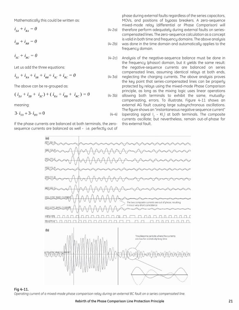
phase during external faults regardless of the series capacitors, MOVs, and positions of bypass breakers. A zero-sequence mixed-mode relay (differential or Phase Comparison) will therefore perform adequately during external faults on series- compensated lines. The zero-sequence calculation as a concept is valid in both time and frequency domains. The above analysis was done in the time domain and automatically applies to the frequency domain.
Analysis of the negative-sequence balance must be done in the frequency (phasor) domain, but it yields the same result: the negative-sequence currents are balanced on series compensated lines, assuming identical relays at both ends, neglecting the charging currents. The above analysis proves the key point that series-compensated lines can be properly protected by relays using the mixed-mode Phase Comparison principle, as long as the mixing logic uses linear operations allowing both terminals to exhibit the same, mutually-compensating, errors. To illustrate, Figure 4-11 shows an external AG fault causing large subsynchronous oscillations. The fi gure shows an “instantaneous negative sequence current” (operating signal I2 - KI1) at both terminals. The composite currents oscillate; but nevertheless, remain out-of-phase for this external fault.
033 00 =⋅+⋅ RS ii
Fig 4-11. Operating current of a mixed-mode phase comparison relay during an external BC fault on a series compensated line.
22 Rebirth of the Phase Comparison Line Protection Principle
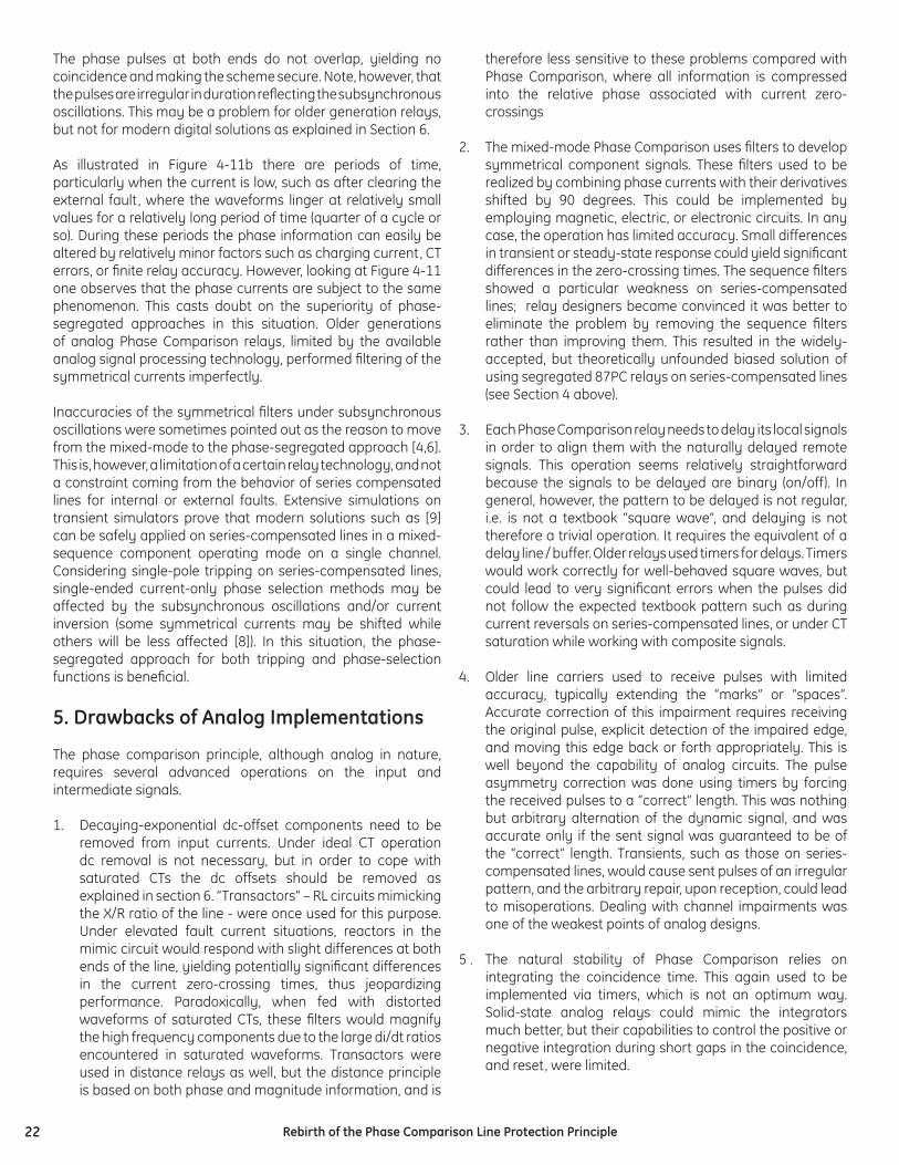
The phase pulses at both ends do not overlap, yielding no coincidence and making the scheme secure. Note, however, that the pulses are irregular in duration refl ecting the subsynchronous oscillations. This may be a problem for older generation relays, but not for modern digital solutions as explained in Section 6.
As illustrated in Figure 4-11b there are periods of time, particularly when the current is low, such as after clearing the external fault, where the waveforms linger at relatively small values for a relatively long period of time (quarter of a cycle or so). During these periods the phase information can easily be altered by relatively minor factors such as charging current, CT errors, or fi nite relay accuracy. However, looking at Figure 4-11 one observes that the phase currents are subject to the same phenomenon. This casts doubt on the superiority of phase-segregated approaches in this situation. Older generations of analog Phase Comparison relays, limited by the available analog signal processing technology, performed fi ltering of the symmetrical currents imperfectly.
Inaccuracies of the symmetrical fi lters under subsynchronous oscillations were sometimes pointed out as the reason to move from the mixed-mode to the phase-segregated approach [4,6]. This is, however, a limitation of a certain relay technology, and not a constraint coming from the behavior of series compensated lines for internal or external faults. Extensive simulations on transient simulators prove that modern solutions such as [9] can be safely applied on series-compensated lines in a mixed-sequence component operating mode on a single channel. Considering single-pole tripping on series-compensated lines, single-ended current-only phase selection methods may be affected by the subsynchronous oscillations and/or current inversion (some symmetrical currents may be shifted while others will be less affected [8]). In this situation, the phase-segregated approach for both tripping and phase-selection functions is benefi cial.
5. Drawbacks of Analog Implementations
The phase comparison principle, although analog in nature, requires several advanced operations on the input and intermediate signals.
1. Decaying-exponential dc-offset components need to be removed from input currents. Under ideal CT operation dc removal is not necessary, but in order to cope with saturated CTs the dc offsets should be removed as explained in section 6. “Transactors” – RL circuits mimicking the X/R ratio of the line - were once used for this purpose. Under elevated fault current situations, reactors in the mimic circuit would respond with slight differences at both ends of the line, yielding potentially signifi cant differences in the current zero-crossing times, thus jeopardizing performance. Paradoxically, when fed with distorted waveforms of saturated CTs, these fi lters would magnify the high frequency components due to the large di/dt ratios encountered in saturated waveforms. Transactors were used in distance relays as well, but the distance principle is based on both phase and magnitude information, and is
therefore less sensitive to these problems compared with Phase Comparison, where all information is compressed into the relative phase associated with current zero-crossings
2. The mixed-mode Phase Comparison uses fi lters to develop symmetrical component signals. These fi lters used to be realized by combining phase currents with their derivatives shifted by 90 degrees. This could be implemented by employing magnetic, electric, or electronic circuits. In any case, the operation has limited accuracy. Small differences in transient or steady-state response could yield signifi cant differences in the zero-crossing times. The sequence fi lters showed a particular weakness on series-compensated lines; relay designers became convinced it was better to eliminate the problem by removing the sequence fi lters rather than improving them. This resulted in the widely-accepted, but theoretically unfounded biased solution of using segregated 87PC relays on series-compensated lines (see Section 4 above).
3. Each Phase Comparison relay needs to delay its local signals in order to align them with the naturally delayed remote signals. This operation seems relatively straightforward because the signals to be delayed are binary (on/off). In general, however, the pattern to be delayed is not regular, i.e. is not a textbook “square wave”, and delaying is not therefore a trivial operation. It requires the equivalent of a delay line / buffer. Older relays used timers for delays. Timers would work correctly for well-behaved square waves, but could lead to very signifi cant errors when the pulses did not follow the expected textbook pattern such as during current reversals on series-compensated lines, or under CT saturation while working with composite signals.
4. Older line carriers used to receive pulses with limited accuracy, typically extending the “marks” or “spaces”. Accurate correction of this impairment requires receiving the original pulse, explicit detection of the impaired edge, and moving this edge back or forth appropriately. This is well beyond the capability of analog circuits. The pulse asymmetry correction was done using timers by forcing the received pulses to a “correct” length. This was nothing but arbitrary alternation of the dynamic signal, and was accurate only if the sent signal was guaranteed to be of the “correct” length. Transients, such as those on series-compensated lines, would cause sent pulses of an irregular pattern, and the arbitrary repair, upon reception, could lead to misoperations. Dealing with channel impairments was one of the weakest points of analog designs.
5 . The natural stability of Phase Comparison relies on integrating the coincidence time. This again used to be implemented via timers, which is not an optimum way. Solid-state analog relays could mimic the integrators much better, but their capabilities to control the positive or negative integration during short gaps in the coincidence, and reset, were limited.
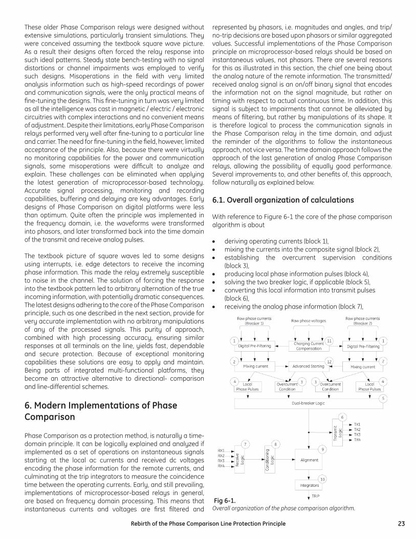
23Rebirth of the Phase Comparison Line Protection Principle
These older Phase Comparison relays were designed without extensive simulations, particularly transient simulations. They were conceived assuming the textbook square wave picture. As a result their designs often forced the relay response into such ideal patterns. Steady state bench-testing with no signal distortions or channel impairments was employed to verify such designs. Misoperations in the fi eld with very limited analysis information such as high-speed recordings of power and communication signals, were the only practical means of fi ne-tuning the designs. This fi ne-tuning in turn was very limited as all the intelligence was cast in magnetic / electric / electronic circuitries with complex interactions and no convenient means of adjustment. Despite their limitations, early Phase Comparison relays performed very well after fi ne-tuning to a particular line and carrier. The need for fi ne-tuning in the fi eld, however, limited acceptance of the principle. Also, because there were virtually no monitoring capabilities for the power and communication signals, some misoperations were diffi cult to analyze and explain. These challenges can be eliminated when applying the latest generation of microprocessor-based technology. Accurate signal processing, monitoring and recording capabilities, buffering and delaying are key advantages. Early designs of Phase Comparison on digital platforms were less than optimum. Quite often the principle was implemented in the frequency domain, i.e. the waveforms were transformed into phasors, and later transformed back into the time domain of the transmit and receive analog pulses.
The textbook picture of square waves led to some designs using interrupts, i.e. edge detectors to receive the incoming phase information. This made the relay extremely susceptible to noise in the channel. The solution of forcing the response into the textbook pattern led to arbitrary alternation of the true incoming information, with potentially dramatic consequences. The latest designs adhering to the core of the Phase Comparison principle, such as one described in the next section, provide for very accurate implementation with no arbitrary manipulations of any of the processed signals. This purity of approach, combined with high processing accuracy, ensuring similar responses at all terminals on the line, yields fast, dependable and secure protection. Because of exceptional monitoring capabilities these solutions are easy to apply and maintain. Being parts of integrated multi-functional platforms, they become an attractive alternative to directional- comparison and line-differential schemes.
6. Modern Implementations of Phase Comparison
Phase Comparison as a protection method, is naturally a time-domain principle. It can be logically explained and analyzed if implemented as a set of operations on instantaneous signals starting at the local ac currents and received dc voltages encoding the phase information for the remote currents, and culminating at the trip integrators to measure the coincidence time between the operating currents. Early, and still prevailing, implementations of microprocessor-based relays in general, are based on frequency domain processing. This means that instantaneous currents and voltages are fi rst fi ltered and
represented by phasors, i.e. magnitudes and angles, and trip/no-trip decisions are based upon phasors or similar aggregated values. Successful implementations of the Phase Comparison principle on microprocessor-based relays should be based on instantaneous values, not phasors. There are several reasons for this as illustrated in this section, the chief one being about the analog nature of the remote information. The transmitted/received analog signal is an on/off binary signal that encodes the information not on the signal magnitude, but rather on timing with respect to actual continuous time. In addition, this signal is subject to impairments that cannot be alleviated by means of fi ltering, but rather by manipulations of its shape. It is therefore logical to process the communication signals in the Phase Comparison relay in the time domain, and adjust the reminder of the algorithms to follow the instantaneous approach, not vice versa. The time domain approach follows the approach of the last generation of analog Phase Comparison relays, allowing the possibility of equally good performance. Several improvements to, and other benefi ts of, this approach, follow naturally as explained below.
6.1. Overall organization of calculations
With reference to Figure 6-1 the core of the phase comparison algorithm is about
• deriving operating currents (block 1), • mixing the currents into the composite signal (block 2), • establishing the overcurrent supervision conditions
(block 3), • producing local phase information pulses (block 4), • solving the two breaker logic, if applicable (block 5), • converting this local information into transmit pulses (block 6), • receiving the analog phase information (block 7),
Fig 6-1. Overall organization of the phase comparison algorithm.
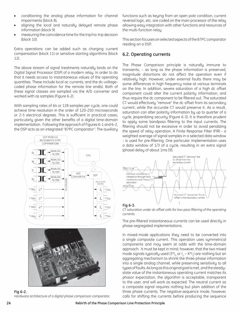
24 Rebirth of the Phase Comparison Line Protection Principle
• conditioning the analog phase information for channel impairments (block 8),
• aligning the local and naturally delayed remote phase information (block 9)
• measuring the coincidence time for the trip/no-trip decision (block 10).
Extra operations can be added such as charging current compensation (block 11) or sensitive starting algorithms (block 12).
The above stream of signal treatments naturally lands on the Digital Signal Processor (DSP) of a modern relay. In order to do that it needs access to instantaneous values of the operating quantities. These include local ac currents, and the dc-voltage-coded phase information for the remote line end(s). Both of these signal classes are sampled via the A/D converter and worked with as samples (Figure 6-2).
With sampling rates of 64 or 128 samples per cycle, one could achieve time resolution in the order of 120-250 microseconds or 2-5 electrical degrees. This is suffi cient in practical cases, particularly given the other benefi ts of a digital time-domain implementation. Following the approach of Figures 6-1 and 6-2, the DSP acts as an integrated “87PC comparator”. The auxiliary
functions such as keying from an open pole condition, current reversal logic, etc. are coded on the main processor of the relay allowing easy integration with other functions and resources of the multi-function relay.
This section focuses on selected aspects of the 87PC comparator residing on a DSP.
6.2. Operating currents
The Phase Comparison principle is naturally immune to transients; – as long as the phase information is preserved, magnitude distortions do not affect the operation even if relatively high. However, under external faults there may be some differences in high frequency noise at various terminals on the line. In addition, severe saturation of a high dc offset component could alter the current polarity information, and thus require the dc component to be fi ltered out. The saturated CT would effectively “remove” the dc offset from its secondary current, while the accurate CT would preserve it . As a result, saturation can alter polarity information by up to quarter of a cycle, jeopardizing security (Figure 6-3). It is therefore prudent to apply some bandpass fi ltering to the input currents. The fi ltering should not be excessive in order to avoid penalizing the speed of relay operation. A Finite Response Filter (FIR) - a weighted average of signal samples in a selected data window - is used for pre-fi ltering. One particular implementation uses a data window of 1/3 of a cycle, resulting in an extra signal (phase) delay of about 1ms [9].
The pre-fi ltered instantaneous currents can be used directly in phase-segregated implementations.
In mixed-mode applications they need to be converted into a single composite current. This operation uses symmetrical components and may seem at odds with the time-domain approach. It must be kept in mind, however, that the two mixed mode signals typically used (3*I0 or I2 – K*I1) are nothing but an aggregating mechanism to shrink the three-phase information into a single analog channel, while preserving sensitivity to all types of faults. As long as this original goal is met, and the steady-state value of the instantaneous operating current matches its phasor expectation, the algorithm is acceptable, transparent to the user, and will work as expected. The neutral current as a composite signal requires nothing but plain addition of the three phase currents. The negative-sequence mode, however, calls for shifting the currents before producing the sequence
Fig 6-2. Hardware architecture of a digital phase comparison comparator.
Fig 6-3.CT saturation under dc offset calls for low-pass fi ltering of the operating currents.
25Rebirth of the Phase Comparison Line Protection Principle
Fig 6-4. Current mixing logic
components, and ultimately the composite signal. This could be done, without introducing unnecessary delay, by applying a pair of orthogonal fi lters. Orthogonal fi lters are two fi lters that yield phase responses shifted by 90 degrees, and preferably have similar magnitude responses, i.e. fi ltering capabilities. The two fi lters are often labeled as direct (D) and quadrature (Q). Their outputs are instantaneous values, but could be treated in a way similar to the real and imaginary parts of a phasor in the frequency domain. One particular implementation of a Phase Comparison relay uses a pair of short-window FIR fi lters to derive the D-Q components while providing extra transient fi ltering. Once the D-Q components are obtained, the instantaneous negative-sequence based composite signal (I2 – K*I1) is created as follows.
ABC phase rotation, phase A as a reference:
ACB phase rotation, phase A as a reference:
Technically, the mixed signal is created as a linear combination of the D-Q components of the phase currents (ABC) as illustrated in Figure 6-4.
As explained in section 4 there is a need to shift the reference phase for the calculations taking into account a particular conductor on which the carrier equipment is installed. This shapes the instantaneous value of the operating signal in a way that boosts its immunity to noise expected at the crest values of the voltage in the phase used by the carrier.
Equations (1) are still valid when shifting the reference. The indices must be rotated accordingly ABC® BCA ® CAB. For example, the mixed signal referenced to the B-phase is calculated as:
Note that equations (6-1 and 6-2) are linear combinations of current samples, as long as the operations of pre-fi ltering and deriving the orthogonal components are linear, as they should be. This guarantees security on external faults regardless of any transients, as long as the hardware/algorithms are the same at all line terminals, as they should be. With both terminals applying the same linear processing, the two mixed currents will always be out-of-phase as waveforms, regardless of their possible distortions and transients.
(6-1a)
(6-1b)
(6-2)
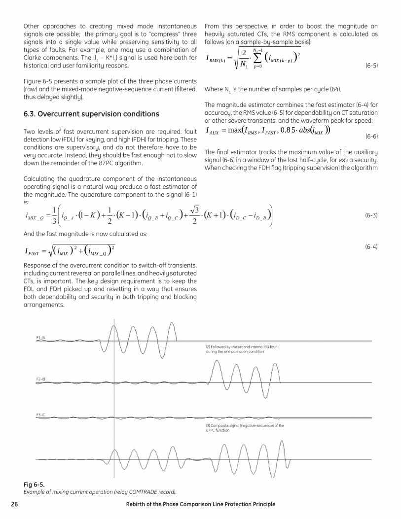
26 Rebirth of the Phase Comparison Line Protection Principle
Other approaches to creating mixed mode instantaneous signals are possible; the primary goal is to “compress” three signals into a single value while preserving sensitivity to all types of faults. For example, one may use a combination of Clarke components. The (I2 – K*I1) signal is used here both for historical and user familiarity reasons.
Figure 6-5 presents a sample plot of the three phase currents (raw) and the mixed-mode negative-sequence current (fi ltered, thus delayed slightly).
6.3. Overcurrent supervision conditions
Two levels of fast overcurrent supervision are required: fault detection low (FDL) for keying, and high (FDH) for tripping. These conditions are supervisory, and do not therefore have to be very accurate. Instead, they should be fast enough not to slow down the remainder of the 87PC algorithm.
Calculating the quadrature component of the instantaneous operating signal is a natural way produce a fast estimator of the magnitude. The quadrature component to the signal (6-1) is:
And the fast magnitude is now calculated as:
Response of the overcurrent condition to switch-off transients, including current reversal on parallel lines, and heavily saturated CTs, is important. The key design requirement is to keep the FDL and FDH picked up and resetting in a way that ensures both dependability and security in both tripping and blocking arrangements.
From this perspective, in order to boost the magnitude on heavily saturated CTs, the RMS component is calculated as follows (on a sample-by-sample basis):
(6-5)
Where N1 is the number of samples per cycle (64).
The magnitude estimator combines the fast estimator (6-4) for accuracy, the RMS value (6-5) for dependability on CT saturation or other severe transients, and the waveform peak for speed:
(6-6)
The fi nal estimator tracks the maximum value of the auxiliary signal (6-6) in a window of the last half-cycle, for extra security.When checking the FDH fl ag (tripping supervision) the algorithm
( ) ( )2 _
2 QMIXMIXFAST iiI +=
( )∑−
=−⋅=
1
0
2 )(
1)(
1
2 N
ppkMIXkRMS i
NI
( )( )MIXFASTRMSAUX iabsIII ⋅= 5 8.0,,max
(6-3)
(6-4)
Fig 6-5. Example of mixing current operation (relay COMTRADE record).
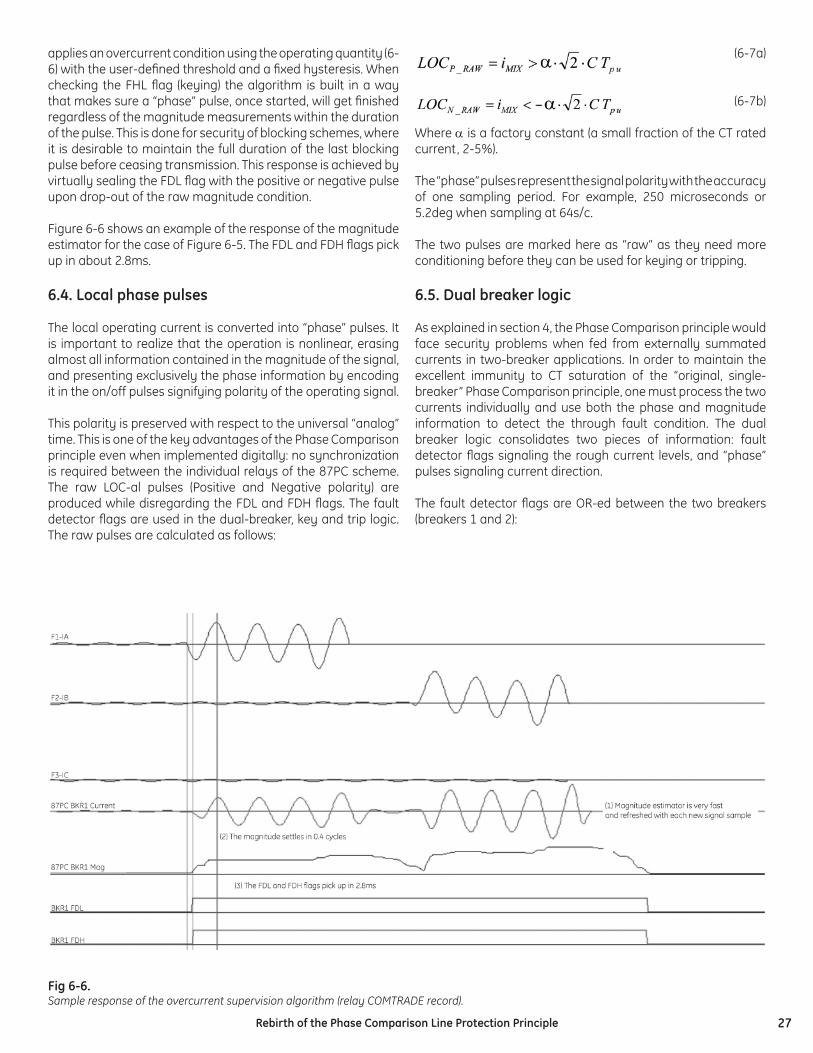
27Rebirth of the Phase Comparison Line Protection Principle
applies an overcurrent condition using the operating quantity (6-6) with the user-defi ned threshold and a fi xed hysteresis. When checking the FHL fl ag (keying) the algorithm is built in a way that makes sure a “phase” pulse, once started, will get fi nished regardless of the magnitude measurements within the duration of the pulse. This is done for security of blocking schemes, where it is desirable to maintain the full duration of the last blocking pulse before ceasing transmission. This response is achieved by virtually sealing the FDL fl ag with the positive or negative pulse upon drop-out of the raw magnitude condition.
Figure 6-6 shows an example of the response of the magnitude estimator for the case of Figure 6-5. The FDL and FDH fl ags pick up in about 2.8ms.
6.4. Local phase pulses
The local operating current is converted into “phase” pulses. It is important to realize that the operation is nonlinear, erasing almost all information contained in the magnitude of the signal, and presenting exclusively the phase information by encoding it in the on/off pulses signifying polarity of the operating signal.
This polarity is preserved with respect to the universal “analog” time. This is one of the key advantages of the Phase Comparison principle even when implemented digitally: no synchronization is required between the individual relays of the 87PC scheme.The raw LOC-al pulses (Positive and Negative polarity) are produced while disregarding the FDL and FDH fl ags. The fault detector fl ags are used in the dual-breaker, key and trip logic. The raw pulses are calculated as follows:
(6-7a)
(6-7b)
Where α is a factory constant (a small fraction of the CT rated current, 2-5%).
The “phase” pulses represent the signal polarity with the accuracy of one sampling period. For example, 250 microseconds or 5.2deg when sampling at 64s/c.
The two pulses are marked here as “raw” as they need more conditioning before they can be used for keying or tripping.
6.5. Dual breaker logic
As explained in section 4, the Phase Comparison principle would face security problems when fed from externally summated currents in two-breaker applications. In order to maintain the excellent immunity to CT saturation of the “original, single-breaker” Phase Comparison principle, one must process the two currents individually and use both the phase and magnitude information to detect the through fault condition. The dual breaker logic consolidates two pieces of information: fault detector fl ags signaling the rough current levels, and “phase” pulses signaling current direction.
The fault detector fl ags are OR-ed between the two breakers (breakers 1 and 2):
Fig 6-6. Sample response of the overcurrent supervision algorithm (relay COMTRADE record).
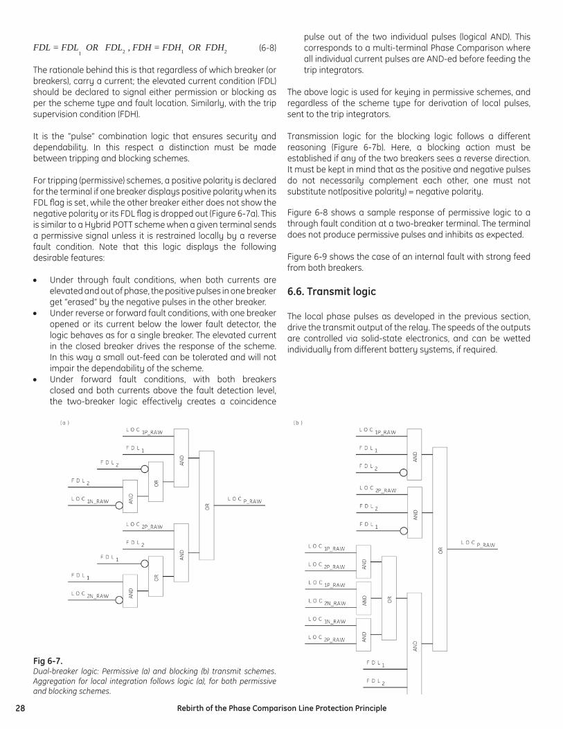
28 Rebirth of the Phase Comparison Line Protection Principle
(6-8)
The rationale behind this is that regardless of which breaker (or breakers), carry a current; the elevated current condition (FDL) should be declared to signal either permission or blocking as per the scheme type and fault location. Similarly, with the trip supervision condition (FDH).
It is the “pulse” combination logic that ensures security and dependability. In this respect a distinction must be made between tripping and blocking schemes.
For tripping (permissive) schemes, a positive polarity is declared for the terminal if one breaker displays positive polarity when its FDL fl ag is set, while the other breaker either does not show the negative polarity or its FDL fl ag is dropped out (Figure 6-7a). This is similar to a Hybrid POTT scheme when a given terminal sends a permissive signal unless it is restrained locally by a reverse fault condition. Note that this logic displays the following desirable features:
• Under through fault conditions, when both currents are elevated and out of phase, the positive pulses in one breaker get “erased” by the negative pulses in the other breaker.
• Under reverse or forward fault conditions, with one breaker opened or its current below the lower fault detector, the logic behaves as for a single breaker. The elevated current in the closed breaker drives the response of the scheme. In this way a small out-feed can be tolerated and will not impair the dependability of the scheme.
• Under forward fault conditions, with both breakers closed and both currents above the fault detection level, the two-breaker logic effectively creates a coincidence
pulse out of the two individual pulses (logical AND). This corresponds to a multi-terminal Phase Comparison where all individual current pulses are AND-ed before feeding the trip integrators.
The above logic is used for keying in permissive schemes, and regardless of the scheme type for derivation of local pulses, sent to the trip integrators.
Transmission logic for the blocking logic follows a different reasoning (Figure 6-7b). Here, a blocking action must be established if any of the two breakers sees a reverse direction. It must be kept in mind that as the positive and negative pulses do not necessarily complement each other, one must not substitute not(positive polarity) = negative polarity.
Figure 6-8 shows a sample response of permissive logic to a through fault condition at a two-breaker terminal. The terminal does not produce permissive pulses and inhibits as expected.
Figure 6-9 shows the case of an internal fault with strong feed from both breakers.
6.6. Transmit logic
The local phase pulses as developed in the previous section, drive the transmit output of the relay. The speeds of the outputs are controlled via solid-state electronics, and can be wetted individually from different battery systems, if required.
FDL = FDL1 OR FDL2 , FDH = FDH1 OR FDH2
Fig 6-7. Dual-breaker logic: Permissive (a) and blocking (b) transmit schemes. Aggregation for local integration follows logic (a), for both permissive and blocking schemes.
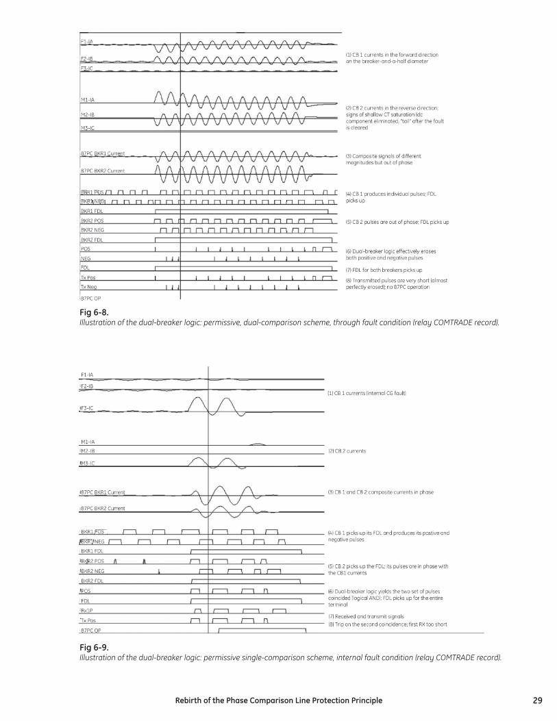
29Rebirth of the Phase Comparison Line Protection Principle
Fig 6-8.Illustration of the dual-breaker logic: permissive, dual-comparison scheme, through fault condition (relay COMTRADE record).
Fig 6-9. Illustration of the dual-breaker logic: permissive single-comparison scheme, internal fault condition (relay COMTRADE record).
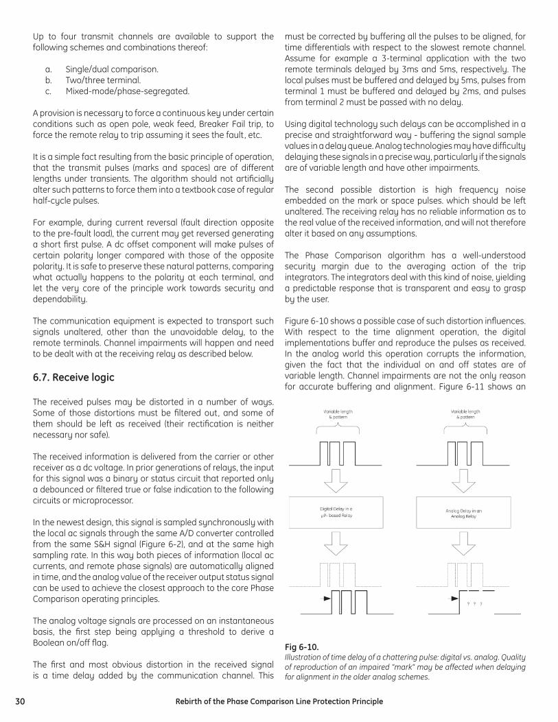
30 Rebirth of the Phase Comparison Line Protection Principle
Up to four transmit channels are available to support the following schemes and combinations thereof:
a. Single/dual comparison.b. Two/three terminal. c. Mixed-mode/phase-segregated.
A provision is necessary to force a continuous key under certain conditions such as open pole, weak feed, Breaker Fail trip, to force the remote relay to trip assuming it sees the fault, etc.
It is a simple fact resulting from the basic principle of operation, that the transmit pulses (marks and spaces) are of different lengths under transients. The algorithm should not artifi cially alter such patterns to force them into a textbook case of regular half-cycle pulses.
For example, during current reversal (fault direction opposite to the pre-fault load), the current may get reversed generating a short fi rst pulse. A dc offset component will make pulses of certain polarity longer compared with those of the opposite polarity. It is safe to preserve these natural patterns, comparing what actually happens to the polarity at each terminal, and let the very core of the principle work towards security and dependability.
The communication equipment is expected to transport such signals unaltered, other than the unavoidable delay, to the remote terminals. Channel impairments will happen and need to be dealt with at the receiving relay as described below.
6.7. Receive logic
The received pulses may be distorted in a number of ways. Some of those distortions must be fi ltered out, and some of them should be left as received (their rectifi cation is neither necessary nor safe).
The received information is delivered from the carrier or other receiver as a dc voltage. In prior generations of relays, the input for this signal was a binary or status circuit that reported only a debounced or fi ltered true or false indication to the following circuits or microprocessor.
In the newest design, this signal is sampled synchronously with the local ac signals through the same A/D converter controlled from the same S&H signal (Figure 6-2), and at the same high sampling rate. In this way both pieces of information (local ac currents, and remote phase signals) are automatically aligned in time, and the analog value of the receiver output status signal can be used to achieve the closest approach to the core Phase Comparison operating principles.
The analog voltage signals are processed on an instantaneous basis, the fi rst step being applying a threshold to derive a Boolean on/off fl ag.
The fi rst and most obvious distortion in the received signal is a time delay added by the communication channel. This
must be corrected by buffering all the pulses to be aligned, for time differentials with respect to the slowest remote channel. Assume for example a 3-terminal application with the two remote terminals delayed by 3ms and 5ms, respectively. The local pulses must be buffered and delayed by 5ms, pulses from terminal 1 must be buffered and delayed by 2ms, and pulses from terminal 2 must be passed with no delay.
Using digital technology such delays can be accomplished in a precise and straightforward way - buffering the signal sample values in a delay queue. Analog technologies may have diffi culty delaying these signals in a precise way, particularly if the signals are of variable length and have other impairments.
The second possible distortion is high frequency noise embedded on the mark or space pulses. which should be left unaltered. The receiving relay has no reliable information as to the real value of the received information, and will not therefore alter it based on any assumptions.
The Phase Comparison algorithm has a well-understood security margin due to the averaging action of the trip integrators. The integrators deal with this kind of noise, yielding a predictable response that is transparent and easy to grasp by the user.
Figure 6-10 shows a possible case of such distortion infl uences. With respect to the time alignment operation, the digital implementations buffer and reproduce the pulses as received. In the analog world this operation corrupts the information, given the fact that the individual on and off states are of variable length. Channel impairments are not the only reason for accurate buffering and alignment. Figure 6-11 shows an
Fig 6-10. Illustration of time delay of a chattering pulse: digital vs. analog. Quality of reproduction of an impaired “mark” may be affected when delaying for alignment in the older analog schemes.
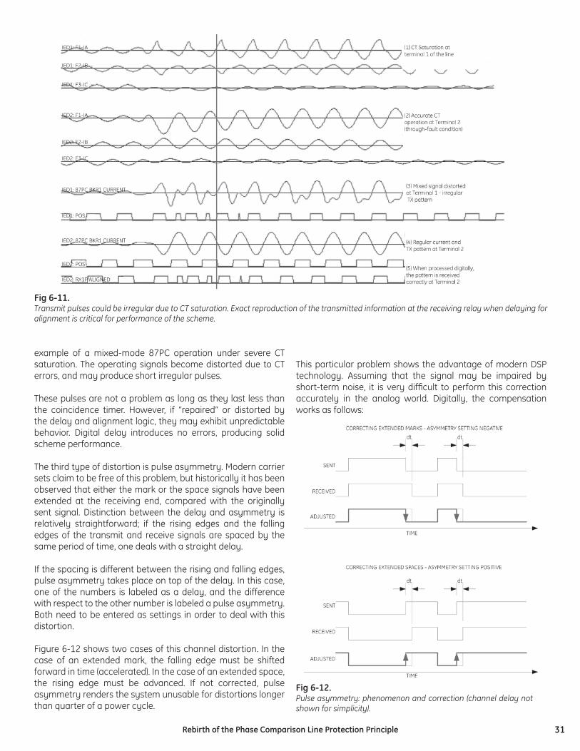
31Rebirth of the Phase Comparison Line Protection Principle
example of a mixed-mode 87PC operation under severe CT saturation. The operating signals become distorted due to CT errors, and may produce short irregular pulses.
These pulses are not a problem as long as they last less than the coincidence timer. However, if “repaired” or distorted by the delay and alignment logic, they may exhibit unpredictable behavior. Digital delay introduces no errors, producing solid scheme performance.
The third type of distortion is pulse asymmetry. Modern carrier sets claim to be free of this problem, but historically it has been observed that either the mark or the space signals have been extended at the receiving end, compared with the originally sent signal. Distinction between the delay and asymmetry is relatively straightforward; if the rising edges and the falling edges of the transmit and receive signals are spaced by the same period of time, one deals with a straight delay.
If the spacing is different between the rising and falling edges, pulse asymmetry takes place on top of the delay. In this case, one of the numbers is labeled as a delay, and the difference with respect to the other number is labeled a pulse asymmetry. Both need to be entered as settings in order to deal with this distortion.
Figure 6-12 shows two cases of this channel distortion. In the case of an extended mark, the falling edge must be shifted forward in time (accelerated). In the case of an extended space, the rising edge must be advanced. If not corrected, pulse asymmetry renders the system unusable for distortions longer than quarter of a power cycle.
This particular problem shows the advantage of modern DSP technology. Assuming that the signal may be impaired by short-term noise, it is very diffi cult to perform this correction accurately in the analog world. Digitally, the compensation works as follows:
Fig 6-11. Transmit pulses could be irregular due to CT saturation. Exact reproduction of the transmitted information at the receiving relay when delaying for alignment is critical for performance of the scheme.
Fig 6-12. Pulse asymmetry: phenomenon and correction (channel delay not shown for simplicity).
32 Rebirth of the Phase Comparison Line Protection Principle
The entire algorithm of the Phase Comparison is delayed by the pulse asymmetry setting (a few milliseconds). This requires our ability to “go back in time” and adjust the received information after seeing the impaired edge. First, it is confi rmed that the edge was actually subjected to pulse asymmetry.. Secondly, the algorithm shifts this edge by the amount of the pulse asymmetry setting. In this way the original pulse is passed unaltered with the exception of exact and explicit adjustment of the edge in question.
Digitally this operation is a series of simple manipulations on data buffers. In the analog world, when accomplished with timers, this operation may alter the original information and lead to problems. In practice the extra delay in processing the data is shorter, unless it is the slowest remote channel that is affected by the pulse asymmetry.
Otherwise, the already introduced delay to “wait” for the slowest channel works towards facilitating this feature. Figure 6-13 illustrates the alignment algorithm. The fi gure shows local current, received RX voltage, and the remote pulse aligned with the local pulses accounting for the channel delay setting.
Being communication-dependent, a Phase Comparison relay should treat information delivered from the remote terminals with the same criticality as the local ac currents. This includes monitoring for troubleshooting purposes, accountability, and continuous improvement capability for products and installations. Modern microprocessor-based Phase Comparison relays that sample their binary dc input voltages for analog level at the same high sampling rate as they do for analog signal inputs provide great analysis tools - they include all the measured and derived instantaneous signals in their oscillographic records (COMTRADE fi les). These include fl ags driving transmission, received dc voltage, local ac currents, and all relevant instantaneous signals leading towards the trip/no-trip condition. Having four receive channels,
it is even possible to loop back the transmit voltages to monitor both the signal connected to local carrier equipment, and that received at the remote location (see Figure 6-14).
Figure 6-15 shows an example of the monitoring capabilities by depicting the received voltage as an analog signal sampled by the relay and zooming-in on minor distortions in this signal.
6.8. Integration and coincidence timing
Fig 6-13. Illustration of the alignment logic (relay COMTRADE record).
Fig 6-15.Example of high-resolution carrier/relay monitoring.
Fig 6-14. Using spare RX channels (RX2) for complete high-resolution carrier/relay monitoring..
33Rebirth of the Phase Comparison Line Protection Principle
Section 4.3 above explained coincidence timing at the top application level. Here we explain exactly how to achieve this timing in the most effective way.
After all the local and remote pulses are aligned and conditioned, a coincidence condition is established as per the number of terminals and type of the scheme (tripping vs. blocking). For example, for a 3-terminal permissive scheme the condition becomes:
(6-9)
The above is executed for positive polarity in single-comparison schemes, and independently for positive and negative polarities in dual-comparison schemes.
The coincidence condition drives an explicitly implemented integrator (summator). In one particular application the integrator counts down by 10 units if the coincidence input is in logic 1; counts down by 5 counts if the coincidence input is in logic 0 momentarily; and counts down by 20 if the input is in logic 0 for longer periods of time. This brings extra security under chattering inputs, allows an eventual trip in a clear situation, and provides full re-set of the integrator before the next coincidence period.
The output of the integrator (or two integrators in dual-comparison schemes) is compared with the coincidence timer setting yielding the fi nal trip/no-trip fl ag.
Figure 6-16 shows an example of the coincidence integration for an internal fault as recorded in a Comtrade fi le by the relay under test.
6.9. Charging current compensation
As explained in section 4, charging current leaking from a long line during through fault conditions shifts the terminal currents toward each other, jeopardizing security and/or calling for increased coincidence timer setting, thus hurting the sensitivity/dependability of the scheme.
This obstacle can be alleviated by applying charging current compensation. Based on the zero- and positive-sequence capacitive shunt impedances of the line, the relay calculates the line charging current based on the voltage signals, and uses it to compensate the measured currents.
The following aspects make this approach a good approximation rather than an exact calculation:
1. It is not known at a given terminal how much capacitive current is supplied through this terminal versus other terminals. Typically schemes assume an equal split between all line terminals. This is of secondary value; in most cases good correction takes place as long as the total current subtracted is close to the actual value, regardless of the split between or among the terminals.
2. The voltage profi le along the line is not fl at, and capacitance is distributed along the line. The relays use lump capacitance models and terminal voltages. This approximation is relatively close as during external faults the voltage profi le is approximately linear along the line length.
3. The capacitive current contains high frequency noise. The relays measure the frequency spectrum up to a designed upper frequency limit.
21 REMANDREMANDLOCANDFDHX =
Fig 6-16.Illustration of the trip integration logic (relay COMTRADE record).
34 Rebirth of the Phase Comparison Line Protection Principle
One particular approach calculates the charging current on a per phase basis, as an instantaneous signal, and subtracts it from the measured currents before any other operation geared toward Phase Comparison protection. This approach was fi rst introduced on line-current differential relays [10] and was proved to reduce the impact of the charging current approximately fi ve- to tenfold in fi eld installations.
The operation is straightforward and is based on a numerical derivative of voltages (DvA, DvB and DvC). The instantaneous charging current is calculated as:
(6-10)
where:
(6-11)
Calculating the charging current as an instantaneous value is a prudent approach given the fact that the described phase comparison relay works in the time domain as well. In addition to removing the leaking current, charging current compensation implemented in the time domain equalizes the high frequency components among the line terminals, making the application more secure on cables and long overhead lines.
Again, as explained in section 4, inductance of the compensating shunt reactor is not a negative capacitance. The relay should be set to compensate for the total charging current, while the reactors should be excluded from the relay measurements by external paralleling of the line and reactor CTs.
6.10. Advanced starting algorithms
Some lines may exhibit persistent content of the negative-sequence current and/or voltage during normal operation. Untransposed EHV lines, or lines supplying traction circuits are good examples. It is not desirable to continuously key Phase Comparison systems. In such cases advanced starting methods are required. Different methods could be used, one of the most popular being based on the increase in negative sequence voltage augmented with a small amount of negative-sequence current:
(6-12)
This approach is similar to concept of an offset impedance for the negative-sequence ground directional overcurrent elements [11]. Operating principle (6-12) can be easily implemented in the time domain as illustrated by equations (6-1) through (6-4).
Other advanced approaches include changes in sequence currents and/or voltages, impedance, or combinations.
6.11. Other advanced phase comparison features
Other advanced functions can be implemented taking advantage of digital technology. Practically considered examples are:
Automated measurement of the channel delay.It is possible to initiate a loop-back test under normal system conditions. By measuring the difference between the sent and received pulses, each relay in the scheme can estimate the actual channel delay. For short lines with negligible charging current, the channel delay can be calculated from the misalignment between the local current pulses and the received pulses, assuming that the remote relay keys test messages.
Automated check-back.Under normal system conditions, a relay could initiate transmission and modulate the analog signal to exchange small amounts of information. Ability to abort in cases of system faults, is a key to successful deployment. This feature could replace the guard signal when this is not available. Furthermore, it provides a more comprehensive communications check from one center of relaying intelligence in the microprocessor at one end, to its companion at the other line terminal. This covers all the links in the chain of communication, not just the carrier part of the system.
Automated measurement of the positive-sequence charging current. By measuring the misalignment between the local and remote pulses under through load conditions, the relays could estimate the amount of positive-sequence charging current.
6.12. Modern multi-function platforms
While focusing on the performance and application benefi ts of a modern pure Phase Comparison implementation as described above, users should be aware of the synergistic benefi ts of the many other functions that are integrated in the latest generation of microprocessor relays.
It is interesting to see how multifunctional relay evolution has enabled the new Phase Comparison approach. Consider the earlier-generation microprocessor line relays of either the directional comparison/distance or the current differential type. The affordable digital hardware elements available at that time, limited the number of analog input channels that could be sampled, as well as the sampling rate. Accordingly, there were three or four current input channels for measuring line currents only, and three inputs for line voltage.
Many of these early multifunctional products included breaker failure protection and automatic reclosing with line protection. However, these could only be used if a single breaker fed the line. More common breaker-and-a-half and ring-bus connections had two breakers feeding the line; each breaker had its own CTs and the CT circuits were paralleled external to the line relay. The internal breaker failure and reclosing functions could not be used, and the user had to install separate breaker failure and reclosing relays on a separate breaker panel.
22 IZVSTART offset ⋅+∆=
35Rebirth of the Phase Comparison Line Protection Principle
In the latest relay generation, the drive is to increase the functions in each relay package in order to reduce cost, panel and fl oor space, and wiring. A major breakthrough has been the addition of voltage and current input channels, and the requisite internal processing horsepower, to handle substation current differential relaying (bus and transformer protection with a separate input for each differential zone CT set), or to separately connect the currents from the CTs of each breaker feeding a line to be protected. The line current is developed by mathematical summation or processing of the individual breaker current inputs internal to the line relay.
Separating the CT inputs, adding bus voltage inputs, and upgrading the accuracy and bandwidth (sampling rate) of each input, brings the following functions to benefi t the user:
1. The breaker failure function is provided as a separate and independently operating function for each breaker, using the appropriate currents for that breaker. Each relay thus has two or more instances of the breaker failure logic. These can be used in the breaker-and-a-half or ring- bus confi gurations that are ubiquitous in transmission substations, eliminating the separate breaker panels and relays.
2. Two redundant line protection systems are installed on bulk transmission lines to meet reliability design requirement of no single point of failure that can completely disable an important protective function. In the new generation of relays, the breaker failure protection for two breakers now resides in the box with the line protection and might be disabled by the same single failure that disables the line protection in that box. However, these breaker failure functions are all duplicated in the redundant line relay, so the single-failure risk is eliminated. Furthermore, the adjacent-zone redundant relays (line, bus, or transformer) may also have additional instances of failure protection for the breaker that separates the zones. So there is more redundancy than was ever available in the past – from two to four breaker failure instances – even as the count of relay boxes is reduced.
3. Automatic reclosing is also included as an independently operating function for each of the breakers, and the relay can develop closing supervision signals of dead line/live bus, live line/dead bus, and synchronism from the connected line and bus voltages for each breaker. Redundant line relays can exchange status reports to enable only one reclosing function at a time for a given breaker.
4. If the relay is integrated with a substation automation system using an Ethernet or serial LAN, it is able to provide accurate and timely metering measurements of individual breaker currents, bus and line voltages, as well as line Watt and VAr fl ows, to the substation communications concentrator. It can replace conventional informational meters, RTUs and transducers, and can also display these independent metered values on its panel.
5. As the measurements for the individual breakers are separated, the control outputs are separated as well. Thus, the relay can serve as the breaker or switch control conduit for SCADA, or for local operators at a substation console, all via the LAN. The relay panel controls can be used for backup, eliminating separate panel switches. It is critically important to recognize the value of performing these control operations through the relay; doing so verifi es that the relay is able to trip the breaker for faults without performing a local maintenance-style tripping test.
6. With individual current inputs captured with high sampling rates, and with greater fault record memory capacity, the relay can capture oscillographic data as good as or better than that captured by a free-standing oscillograph. Again, there are redundant sources of individual measurements that were not available in the past. The oscillographic data is also available over the substation integration LAN for local or remote access by operators, or non-operational users (engineering or maintenance).
Taking advantage of these functional capabilities in the relays, new substation control house design can eliminate more than half of the relay unit count and panel or fl oor space required, along with masses of redundant or daisy-chained wiring. Information and control interfaces from the relays via LAN integration can serve the full range of utility business enterprise users and needs.
With these individual high-bandwidth signal inputs designed into the relay for all of these integration–oriented reasons, the relay now also has the platform of information to carry out Phase Comparison relaying with more pure and secure calculations than were ever possible before. Critically important to the effectiveness of the new 87PC methods are as follows:
1. Separated CT inputs from multiple breakers feeding the line, enabling proper handling of bus through faults at a line terminal as explained in Section 4.8.
2. Developing comparison signals from each breaker separately, and combining with the logic explained in Section 6.5, thus eliminating security risks caused by combining the breaker currents before calculating the comparison signals.
3. Treating channel receiver inputs as analog signals and sampling the waveform at high speed, enabling processing of the receiver outputs that overcomes misbehaviors of the channel that fooled earlier Phase Comparison implementations, as explained in Section 6.7.
36 Rebirth of the Phase Comparison Line Protection Principle
7. Conclusions
Today’s thinning ranks of protective relay engineers are seeking designs that cut workload by simplifying the engineering and maintenance of system protection. They are driven by management to reduce costs while at the same time meeting more stringent system security requirements. The task is easiest if:
1. there is a standard solution that works well for most or all protection needs, from critical bulk transmission lines (including series compensated lines) to multiterminal subtransmission applications
2. the economics allow the user to make a business case for standardizing on this design, which makes it easy to engineer new projects and maintain the consistent installed base of relays
3. the protection standard is as easy to apply in dense urban networks as for lines operating over long distances
4. the scheme is easy to set, with settings not critically dependent on evolution of the power network as new lines or cogenerators are installed, or as the system is switched to unusual operating states. This minimizes the labor required to run coordination studies and update relay settings in the fi eld
5. it is not vulnerable to false tripping during stressed system conditions or recoverable swings, which could contribute to a major blackout
6. the selected standard system provides the suite of information reporting and control facilities to support modern LAN-based substation and enterprise integration of relays
The authors have explained in detail how a new, pure implementation of the long-standing phase comparison protective relaying scheme meets all of these criteria. It is the ideal choice as a standard pilot protection scheme for most utilities.
Table 1 summarizes the salient evaluation points among phase comparison (87PC), line current differential (87L), and directional comparison pilot relaying schemes (DC).
8. References
[1] IEEE Standard 643 - 2005, Power Line Carrier Application Guide.
[2] Sanders, M.P. and Ray, R.E., Power Line Carrier Channel & Application Considerations For Transmission Line Relaying, 50th Protective Relay Conference, Georgia Tech, May 1996 (also available at http://www.pulsartech.com/pulsartech/docs/C045-P0597.pdf).
[3] IEEE Power System Relaying Committee Special Paper of Working Group H9, Considerations In Applying Power Line Carrier For Protective Relaying, available at http://www.pes-psrc.org/h/H9/h09.html, fi nal paper link.
[4] Wilkinson S., “Series Compensated Line Protection Issues”, GE Publication GER-3972 (www.multilin.com).
[5] Kasztenny B., Voloh I., “Application of Distance and Line Current Differential Relays in Breaker-and-a-Half Confi gurations”, 2005/6 IEEE T&D Conference and Expo, Dallas, TX, May 2006.
[6] Elmore W., Pilot Protective Relaying, Marcel Dekker, 2000.
[7] Kasztenny B., Campbell B., Mazereeuw B., “Phase Selection for Single-Pole Tripping – Weak Infeed Conditions and Cross Country Faults”, Proceedings of the 27th Annual Western Protective Relay Conference, Spokane, WA, October 24-26, 2000.
[8] Kasztenny B., “Distance Protection of Series Compensated Lines – Problems and Solutions”, Proceedings of the 28th Annual Western Protective Relay Conference, Spokane, WA, October 22-25, 2001.
[9] L60 Phase Comparison Relay (Instruction Manual), GE Publication GEK-106412, 2005 (www.GEMultilin.com/manuals).
[10] L90 Current Differential Relay (Instruction Manual), GE Publication GEK-113210, 2005 (www.GEMultilin.com/manuals).
[11] Kasztenny B., Sharples D., Campbell B., Pozzuoli M., “Fast Ground Directional Overcurrent Protection–Limitations and Solutions”, Proceedings of the 27th Annual Western Protective Relay Conference, Spokane, WA, October 24-26, 2000.
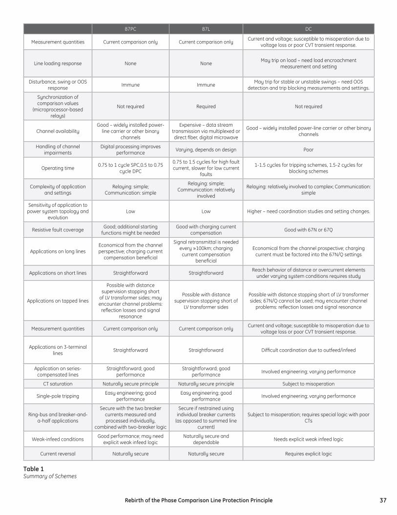
37Rebirth of the Phase Comparison Line Protection Principle
87PC 87L DC
Measurement quantities Current comparison only Current comparison only Current and voltage; susceptible to misoperation due to voltage loss or poor CVT transient response.
Line loading response None None May trip on load – need load encroachment measurement and setting
Disturbance, swing or OOS response Immune Immune May trip for stable or unstable swings – need OOS
detection and trip blocking measurements and settings.
Synchronization of comparison values
(microprocessor-based relays)
Not required Required Not required
Channel availabilityGood – widely installed power-
line carrier or other binary channels
Expensive – data stream transmission via multiplexed or direct fi ber, digital microwave
Good – widely installed power-line carrier or other binary channels
Handling of channel impairments
Digital processing improves performance Varying, depends on design Poor
Operating time 0.75 to 1 cycle SPC,0.5 to 0.75 cycle DPC
0.75 to 1.5 cycles for high fault current, slower for low current
faults
1-1.5 cycles for tripping schemes, 1.5-2 cycles for blocking schemes
Complexity of application and settings
Relaying: simple; Communication: simple
Relaying: simple; Communication: relatively
involved
Relaying: relatively involved to complex; Communication: simple
Sensitivity of application to power system topology and
evolutionLow Low Higher – need coordination studies and setting changes.
Resistive fault coverage Good; additional starting functions might be needed
Good with charging current compensation Good with 67N or 67Q
Applications on long linesEconomical from the channel perspective; charging current
compensation benefi cial
Signal retransmittal is needed every »100km; charging current compensation
benefi cial
Economical from the channel prospective; charging current must be factored into the 67N/Q settings
Applications on short lines Straightforward Straightforward Reach behavior of distance or overcurrent elements under varying system conditions requires study
Applications on tapped lines
Possible with distance supervision stopping short
of LV transformer sides; may encounter channel problems:
refl ection losses and signal resonance
Possible with distance supervision stopping short of
LV transformer sides
Possible with distance stopping short of LV transformer sides; 67N/Q cannot be used; may encounter channel
problems: refl ection losses and signal resonance
Measurement quantities Current comparison only Current comparison only Current and voltage; susceptible to misoperation due to voltage loss or poor CVT transient response.
Applications on 3-terminal lines Straightforward Straightforward Diffi cult coordination due to outfeed/infeed
Application on series-compensated lines
Straightforward; good performance
Straightforward; good performance Involved engineering; varying performance
CT saturation Naturally secure principle Naturally secure principle Subject to misoperation
Single-pole tripping Easy engineering; good performance
Easy engineering; good performance Involved engineering; varying performance
Ring-bus and breaker-and-a-half applications
Secure with the two breaker currents measured and processed individually,
combined with two-breaker logic
Secure if restrained using individual breaker currents
(as opposed to summed line current)
Subject to misoperation; requires special logic with poor CTs
Weak-infeed conditions Good performance; may need explicit weak infeed logic
Naturally secure and dependable Needs explicit weak infeed logic
Current reversal Naturally secure Naturally secure Requires explicit logic
Table 1Summary of Schemes