Embed Size (px)
Citation preview
Recent Progress of ITER Package in ASIPP
ITER
Presenter: Peng Fu The Institute of Plasma Physics, CAS
IAEA, Oct. 17, 2016
1
Content
ITER Package introduction
Main R&D activity and progress
Summary
2
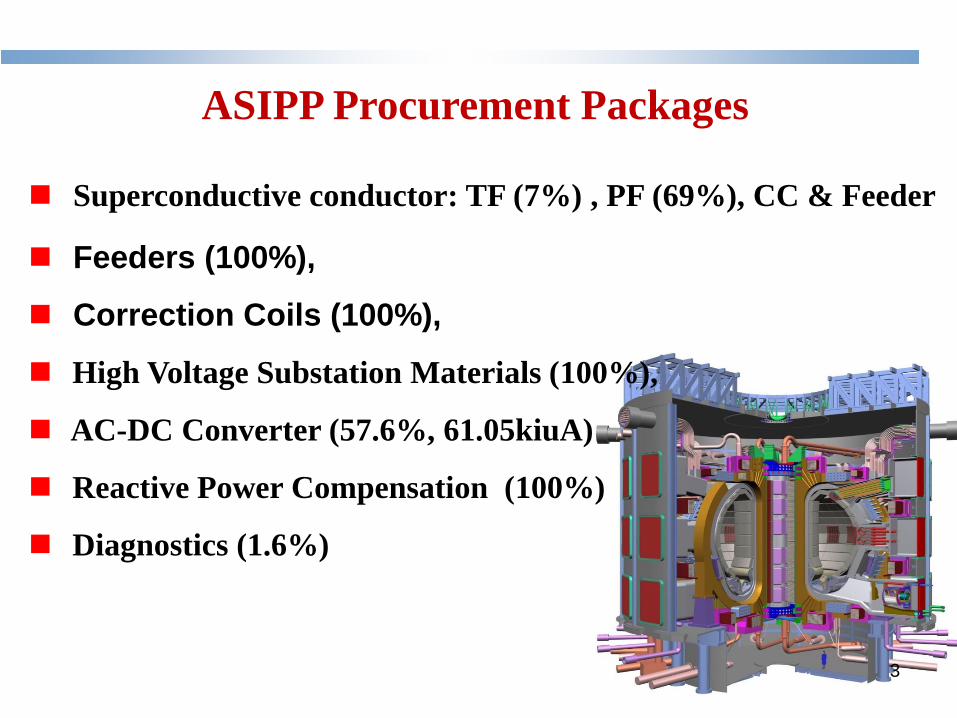
Superconductive conductor: TF (7%) , PF (69%), CC & Feeder
Feeders (100%),
Correction Coils (100%),
High Voltage Substation Materials (100%),
AC-DC Converter (57.6%, 61.05kiuA)
Reactive Power Compensation (100%)
Diagnostics (1.6%)
ASIPP Procurement Packages
3

ITER-ASIPP Management
CN-DA ITER-IO ITER-CAS
committee
ITER-ASIPP -Directory
ITER-ASIPP
-Project Office( ISO9001)
CICC Conductor
Y.Wu
QA
CC
W.Wu
QA
Feeder
Y.Song
QA
Power
supply
P.Fu
QA
Diagnostic
J.Zhao
QA
A successful ITER project is our first priority !
QA (ISO9001) systems
Team (~200)
4
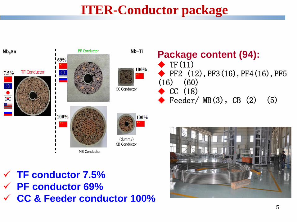
ITER-Conductor package
Package content (94): TF(11) PF2 (12),PF3(16),PF4(16),PF5 (16) (60) CC (18) Feeder/ MB(3),CB (2) (5)
5
TF conductor 7.5%
PF conductor 69%
CC & Feeder conductor 100%
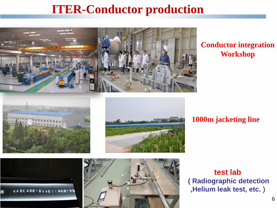
ITER-Conductor production
1000m jacketing line
6
Conductor integration
Workshop
test lab ( Radiographic detection
,Helium leak test, etc. )
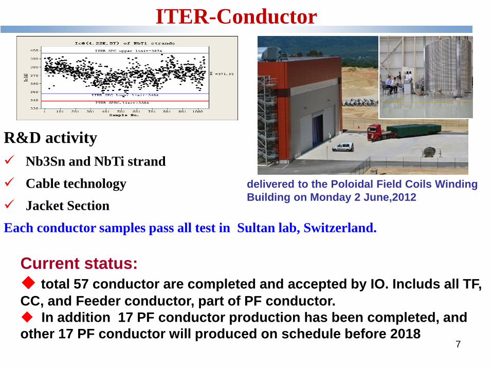
ITER-Conductor
Current status:
total 57 conductor are completed and accepted by IO. Includs all TF,
CC, and Feeder conductor, part of PF conductor.
In addition 17 PF conductor production has been completed, and
other 17 PF conductor will produced on schedule before 2018 7
delivered to the Poloidal Field Coils Winding
Building on Monday 2 June,2012
R&D activity
Nb3Sn and NbTi strand
Cable technology
Jacket Section
Each conductor samples pass all test in Sultan lab, Switzerland.
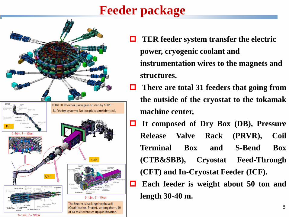
DB
8
TER feeder system transfer the electric
power, cryogenic coolant and
instrumentation wires to the magnets and
structures.
There are total 31 feeders that going from
the outside of the cryostat to the tokamak
machine center,
It composed of Dry Box (DB), Pressure
Release Valve Rack (PRVR), Coil
Terminal Box and S-Bend Box
(CTB&SBB), Cryostat Feed-Through
(CFT) and In-Cryostat Feeder (ICF).
Each feeder is weight about 50 ton and
length 30-40 m.
Feeder package
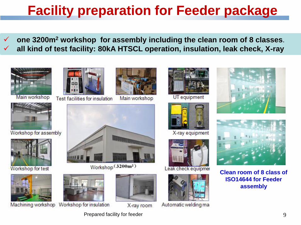
Facility preparation for Feeder package
Clean room of 8 class of
ISO14644 for Feeder
assembly
Prepared facility for feeder
one 3200m2 workshop for assembly including the clean room of 8 classes.
all kind of test facility: 80kA HTSCL operation, insulation, leak check, X-ray
9
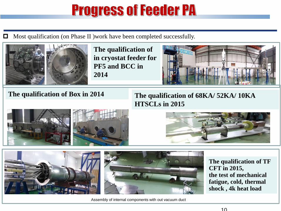
Most qualification (on Phase II )work have been completed successfully.
Assembly of internal components with out vacuum duct
The qualification of TF CFT in 2015, the test of mechanical fatigue, cold, thermal shock , 4k heat load
The qualification of
in cryostat feeder for
PF5 and BCC in
2014
10
The qualification of Box in 2014 The qualification of 68KA/ 52KA/ 10KA
HTSCLs in 2015
PF4 CFT CTB&SBB
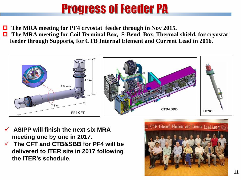
The MRA meeting for PF4 cryostat feeder through in Nov 2015. The MRA meeting for Coil Terminal Box, S-Bend Box, Thermal shield, for cryostat
feeder through Supports, for CTB Internal Element and Current Lead in 2016.
HTSCL
ASIPP will finish the next six MRA
meeting one by one in 2017.
The CFT and CTB&SBB for PF4 will be
delivered to ITER site in 2017 following
the ITER’s schedule.
11
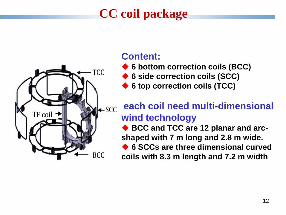
Content: 6 bottom correction coils (BCC)
6 side correction coils (SCC)
6 top correction coils (TCC)
each coil need multi-dimensional
wind technology BCC and TCC are 12 planar and arc-
shaped with 7 m long and 2.8 m wide.
6 SCCs are three dimensional curved
coils with 8.3 m length and 7.2 m width
CC coil package
12
13
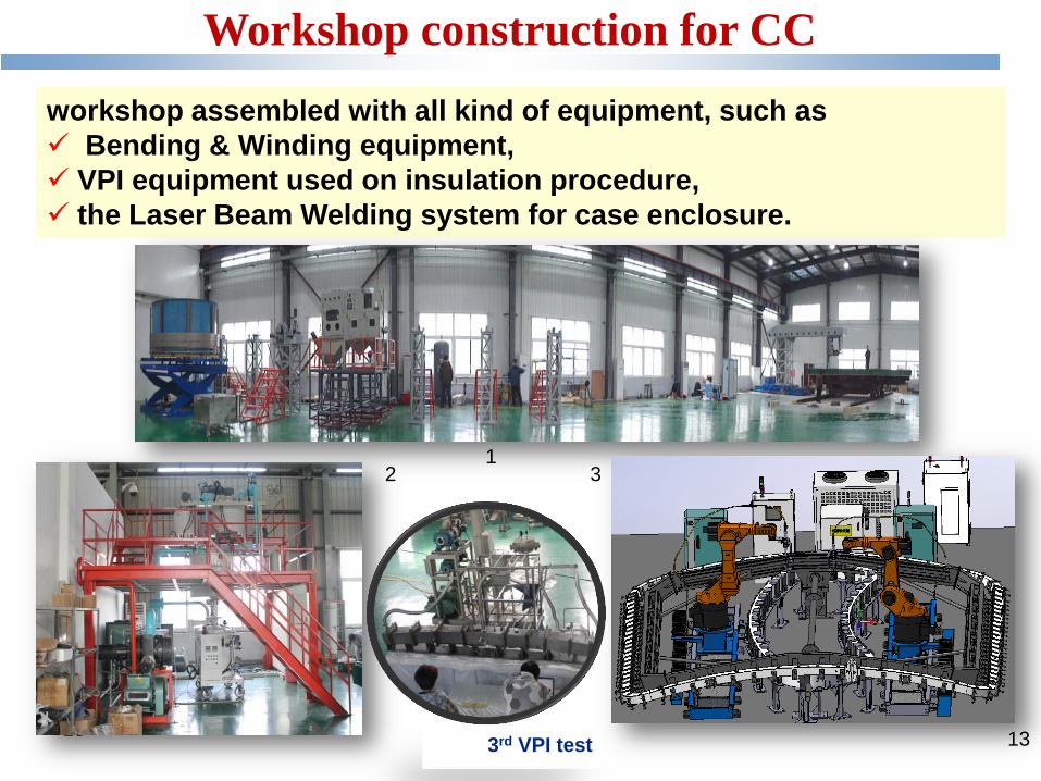
Workshop construction for CC
workshop assembled with all kind of equipment, such as
Bending & Winding equipment,
VPI equipment used on insulation procedure,
the Laser Beam Welding system for case enclosure.
1 3 2
3rd VPI test 13
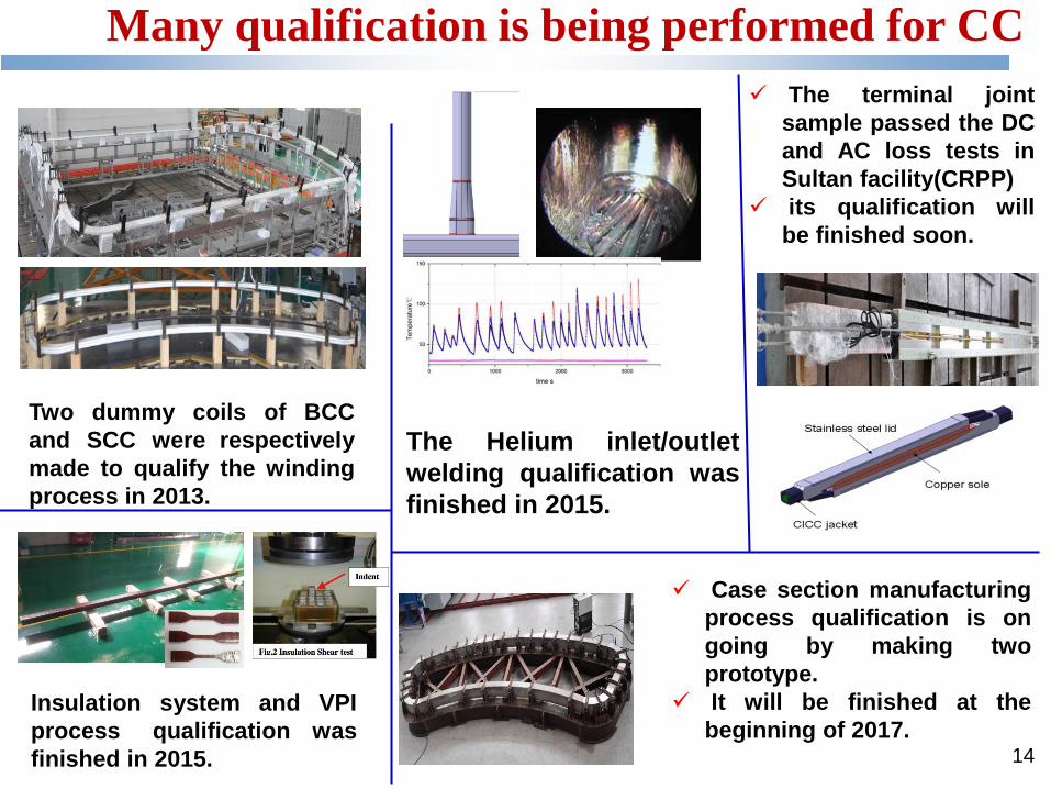
Two dummy coils of BCC
and SCC were respectively
made to qualify the winding
process in 2013.
Insulation system and VPI
process qualification was
finished in 2015.
The Helium inlet/outlet
welding qualification was
finished in 2015.
The terminal joint
sample passed the DC
and AC loss tests in
Sultan facility(CRPP)
its qualification will
be finished soon.
Case section manufacturing
process qualification is on
going by making two
prototype.
It will be finished at the
beginning of 2017.
Many qualification is being performed for CC
14
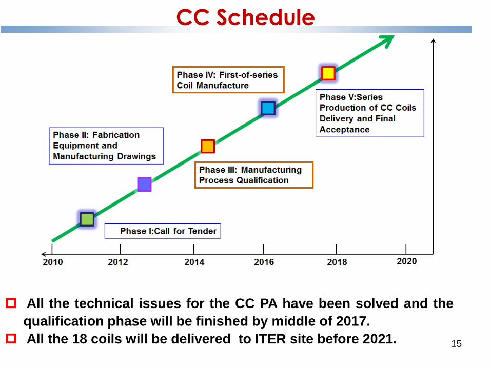
CC Schedule
All the technical issues for the CC PA have been solved and the
qualification phase will be finished by middle of 2017.
All the 18 coils will be delivered to ITER site before 2021. 15
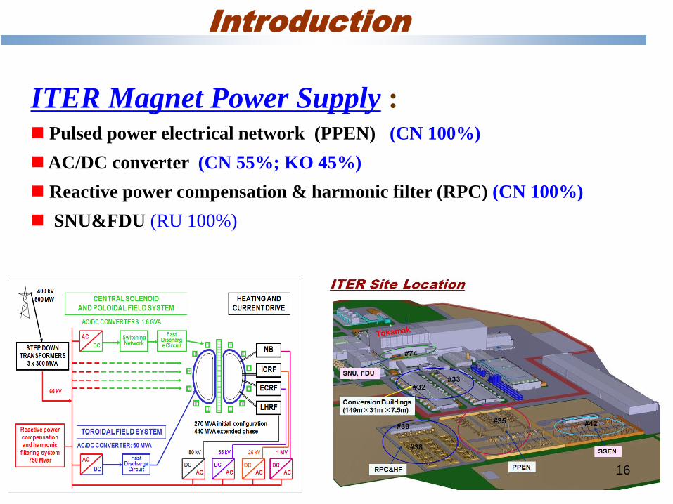
ITER Magnet Power Supply : Pulsed power electrical network (PPEN) (CN 100%)
AC/DC converter (CN 55%; KO 45%)
Reactive power compensation & harmonic filter (RPC) (CN 100%)
SNU&FDU (RU 100%)
Introduction
16
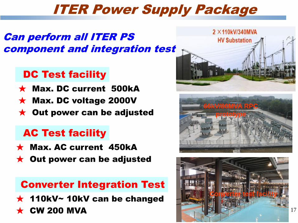
DC Test facility
★ Max. DC current 500kA
★ Max. DC voltage 2000V
★ Out power can be adjusted
Can perform all ITER PS
component and integration test
AC Test facility
★ Max. AC current 450kA
★ Out power can be adjusted
Converter Integration Test
★ 110kV~ 10kV can be changed
★ CW 200 MVA
ITER Power Supply Package
Converter test facility
66kV/80MVA RPC
prototype
17
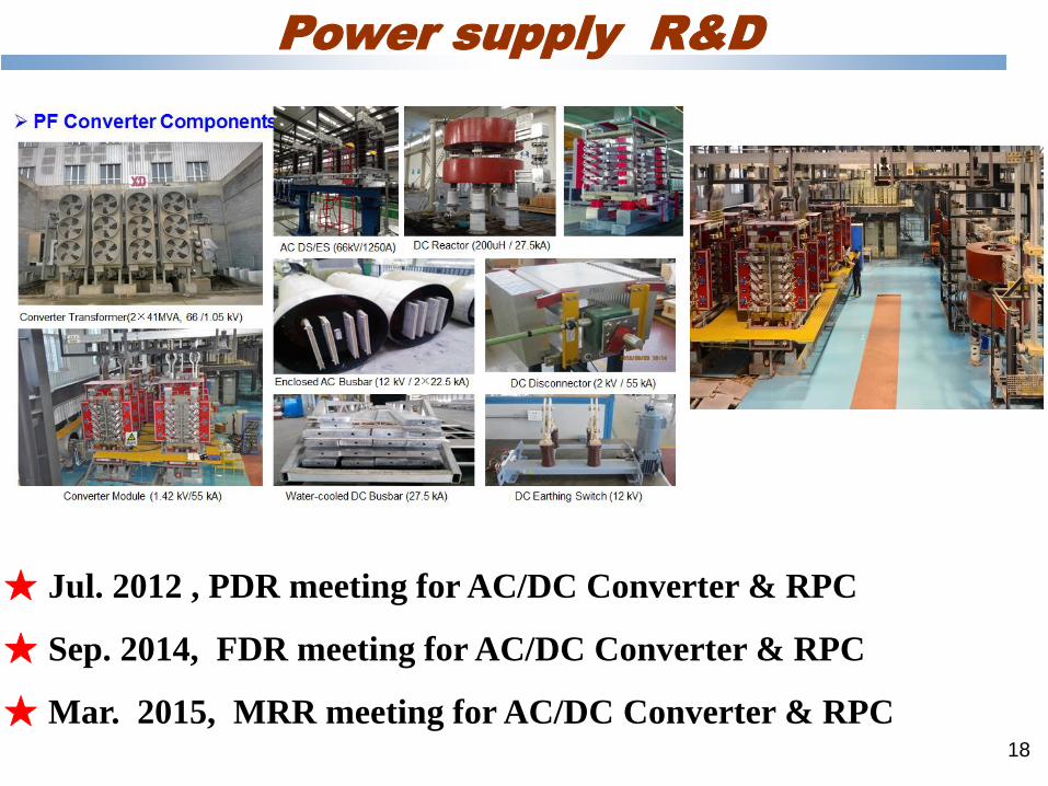
★ Jul. 2012 , PDR meeting for AC/DC Converter & RPC
★ Sep. 2014, FDR meeting for AC/DC Converter & RPC
★ Mar. 2015, MRR meeting for AC/DC Converter & RPC
Power supply R&D
18
ITER Power Supply Package
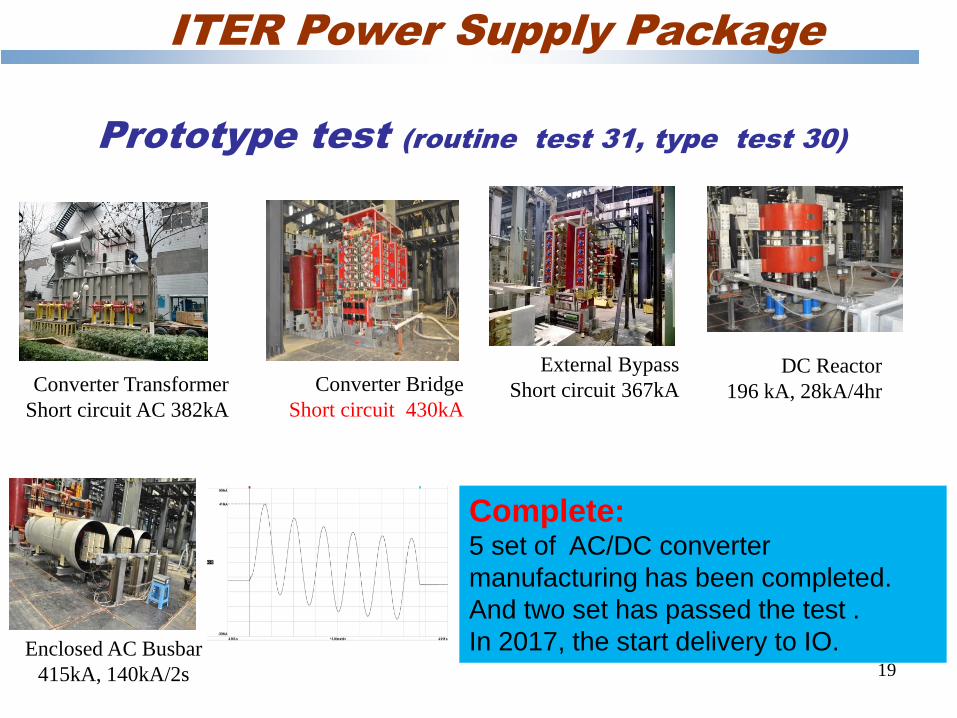
Prototype test (routine test 31, type test 30)
Converter Transformer
Short circuit AC 382kA
Converter Bridge
Short circuit 430kA
External Bypass
Short circuit 367kA
DC Reactor
196 kA, 28kA/4hr
Enclosed AC Busbar
415kA, 140kA/2s 19
Complete: 5 set of AC/DC converter
manufacturing has been completed.
And two set has passed the test .
In 2017, the start delivery to IO.
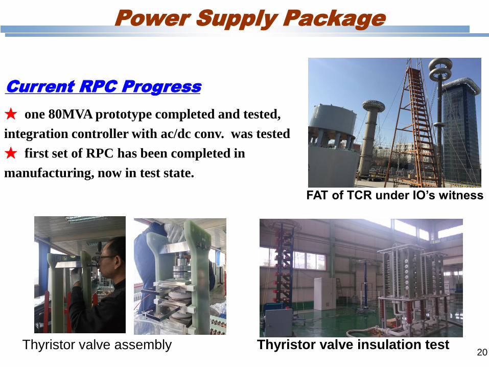
FAT of TCR under IO’s witness
Thyristor valve assembly Thyristor valve insulation test
★ one 80MVA prototype completed and tested,
integration controller with ac/dc conv. was tested
★ first set of RPC has been completed in
manufacturing, now in test state.
Current RPC Progress
Power Supply Package
20
21
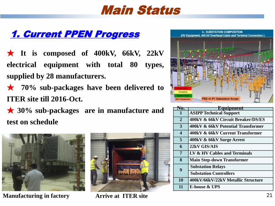
★ It is composed of 400kV, 66kV, 22kV
electrical equipment with total 80 types,
supplied by 28 manufacturers.
★ 70% sub-packages have been delivered to
ITER site till 2016-Oct.
★ 30% sub-packages are in manufacture and
test on schedule
1. Current PPEN Progress
No. Equipment 1 ASIPP Technical Support
2 400kV & 66kV Circuit Breaker/DS/ES
3 400kV & 66kV Potential Transformer
4 400kV & 66kV Current Transformer
5 400kV & 66kV Surge Arrest
6 22kV GIS/AIS
7 LV & HV Cables and Terminals
8 Main Step-down Transformer
9 Substation Relays
Substation Controllers
10 400kV/66kV/22kV Metallic Structure
11 E-house & UPS
Arrive at ITER site Manufacturing in factory
Main Status
22
Summary
To complete ITER package, ASIPP has performed a lot of R&D
activity, and construct much test facility in CN DA’s financial
support
Much equipment has been delivered and accepted by IO, also
many equipment manufacturing has been completed
All package meets current IO schedule.
Main problem:
IO delay IPS, need more storage space, more human resource,
more cost increase ?
Thanks !
EAST
23
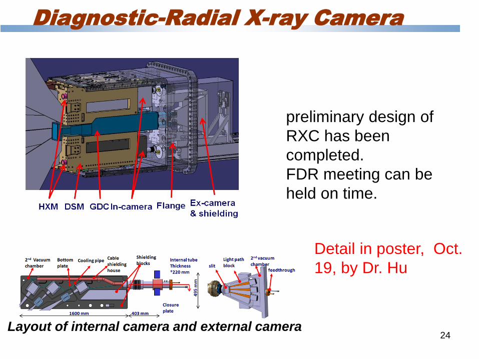
Diagnostic-Radial X-ray Camera
Layout of internal camera and external camera
preliminary design of
RXC has been
completed.
FDR meeting can be
held on time.
24
Detail in poster, Oct.
19, by Dr. Hu
25
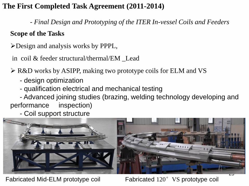
The First Completed Task Agreement (2011-2014)
- Final Design and Prototyping of the ITER In-vessel Coils and Feeders
Scope of the Tasks
Design and analysis works by PPPL,
in coil & feeder structural/thermal/EM _Lead
R&D works by ASIPP, making two prototype coils for ELM and VS
- design optimization
- qualification electrical and mechanical testing
- Advanced joining studies (brazing, welding technology developing and
performance inspection)
- Coil support structure
Fabrication and testing of ELM&120°VS prototype coils _ Lead by ASIPP
Fabricated Mid-ELM prototype coil Fabricated 120°VS prototype coil
26
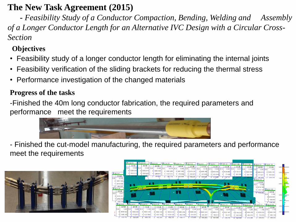
The New Task Agreement (2015) - Feasibility Study of a Conductor Compaction, Bending, Welding and Assembly
of a Longer Conductor Length for an Alternative IVC Design with a Circular Cross-
Section
Objectives
• Feasibility study of a longer conductor length for eliminating the internal joints
• Feasibility verification of the sliding brackets for reducing the thermal stress
• Performance investigation of the changed materials
Progress of the tasks
-Finished the 40m long conductor fabrication, the required parameters and
performance meet the requirements
- Finished the cut-model manufacturing, the required parameters and performance
meet the requirements
27
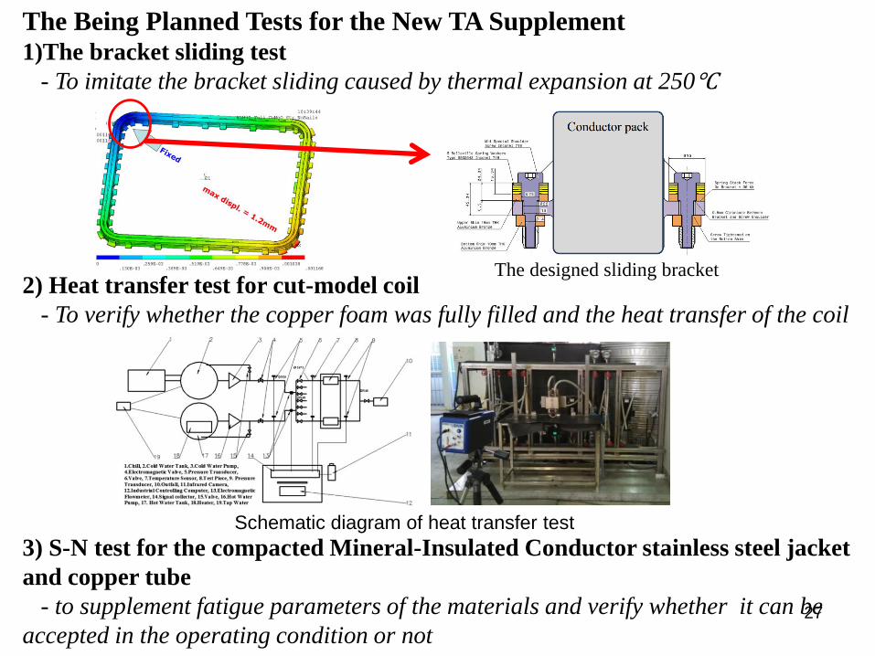
The Being Planned Tests for the New TA Supplement 1)The bracket sliding test
- To imitate the bracket sliding caused by thermal expansion at 250℃
2) Heat transfer test for cut-model coil
- To verify whether the copper foam was fully filled and the heat transfer of the coil
3) S-N test for the compacted Mineral-Insulated Conductor stainless steel jacket
and copper tube
- to supplement fatigue parameters of the materials and verify whether it can be
accepted in the operating condition or not
Schematic diagram of heat transfer test
The designed sliding bracket


![[XLS] Energy Account Upload... · Web view66KV Mandal 66KV Khavad 66KV Kanz 66KV Chharodi 66KV Jhakhwada 132KV Dhandhuka Import from PGVCL Export to PGVCL Import from MGVCL Export](https://img.pdfslide.net/doc/110x75/5abf5f6c7f8b9a7e418e1355/xls-energy-account-uploadweb-view66kv-mandal-66kv-khavad-66kv-kanz-66kv-chharodi.jpg)