Embed Size (px)
Citation preview

Recent updates to the Arnold Mirror Modelerand integration into the evolving NASA
overall design system for large space-based optical systems
William R. Arnold, Sr.NASA Marshall Space Flight Center
AI Solutions Inc., Huntsville, Al. USA 35806
1
WHAT IS THE MODELER?
• For a number of years the Advanced Mirror Technology Development (AMTD) project has been developing design tools and validating manufacturing methods to support the coming generations of large spaced based telescopes. [1,2,3,4,5]
• The challenges of larger size mirrors and limited payload and shroud capacities (for both existing , under development or planned) have created the need for optimization of all aspects of the optics and instruments.
• The Arnold Mirror Modeler is one of those tools intended to make the optimization problem more efficient by radically reducing the time required to generate complex Finite Element models of very large egg‐crate style lightweight mirrors and their suspension systems (both monolith and segmented).
SPIE 9573‐17 Optomechanical Engineering 2015 09‐13 August 2015 in San Diego, Ca United States
WHAT DOES MODELER DO?
7/14/2015 SPIE 9573‐17 Optomechanical Engineering 2015 09‐13 August 2015 in San Diego, Ca United States 3
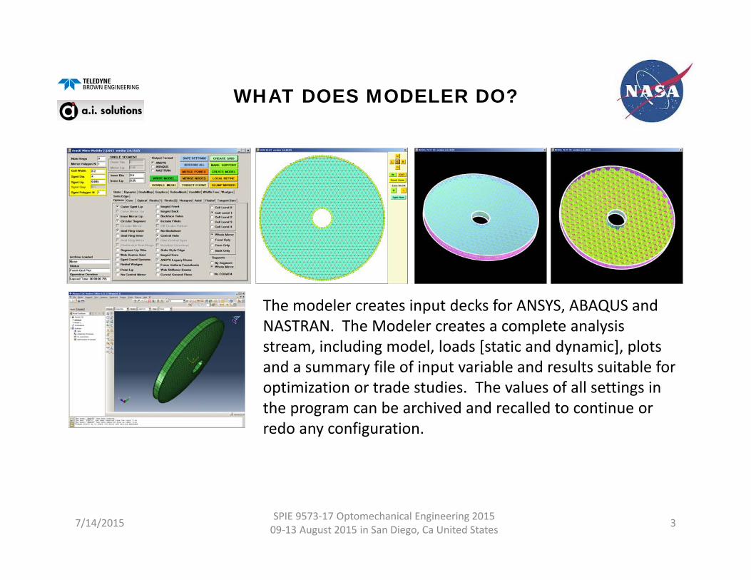
The modeler creates input decks for ANSYS, ABAQUS and NASTRAN. The Modeler creates a complete analysis stream, including model, loads [static and dynamic], plots and a summary file of input variable and results suitable for optimization or trade studies. The values of all settings in the program can be archived and recalled to continue or redo any configuration.
TYPES OF MODELS GENERATED
7/14/2015 SPIE 9573‐17 Optomechanical Engineering 2015 09‐13 August 2015 in San Diego, Ca United States 4
SO WHATS NEW SINCE THE LAST TIME?
SEE THE REFERENCES FOR DETAILS OF EVERYTHING PRIOR VERSIONS OF THE MODELER CAN DO
SPIE 9573‐17 Optomechanical Engineering 2015 09‐13 August 2015 in San Diego, Ca United States7/14/2015 5
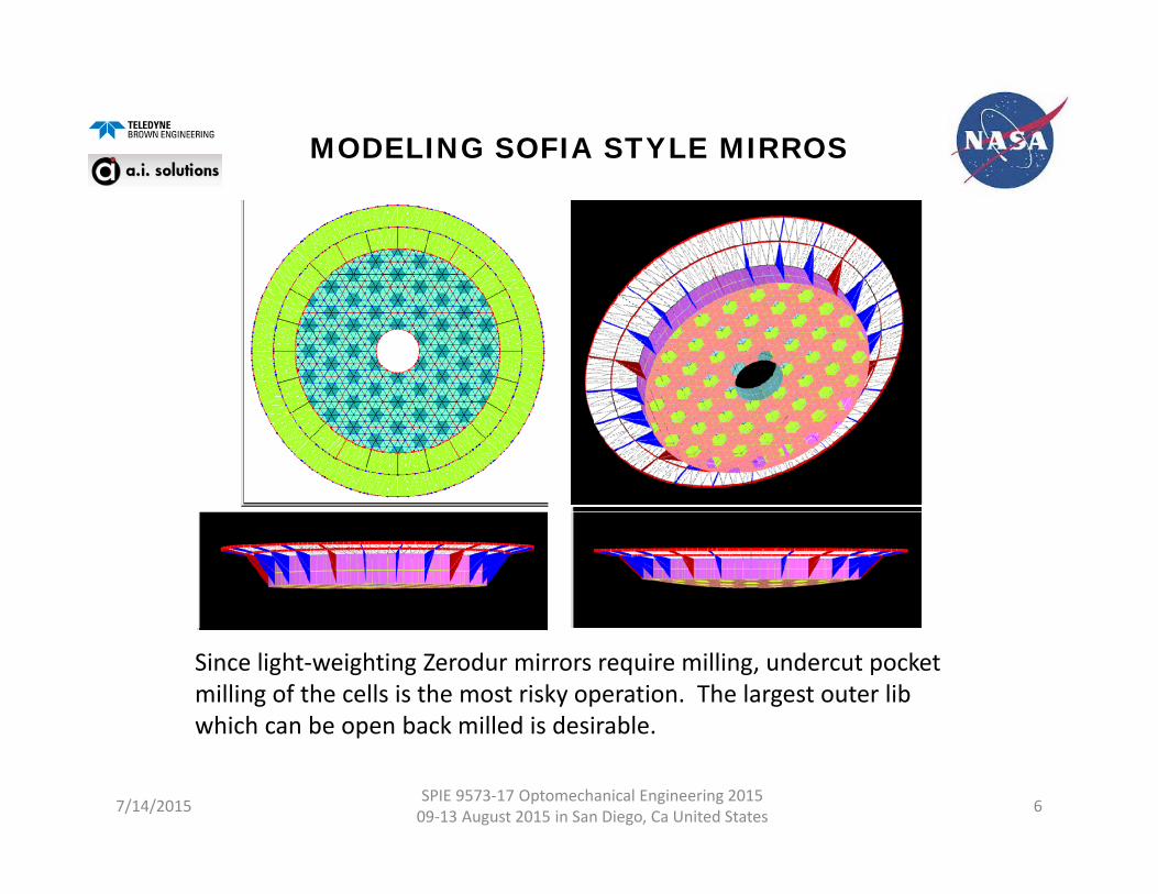
MODELING SOFIA STYLE MIRROS
7/14/2015 SPIE 9573‐17 Optomechanical Engineering 2015 09‐13 August 2015 in San Diego, Ca United States 6
Since light‐weighting Zerodur mirrors require milling, undercut pocket milling of the cells is the most risky operation. The largest outer lib which can be open back milled is desirable.
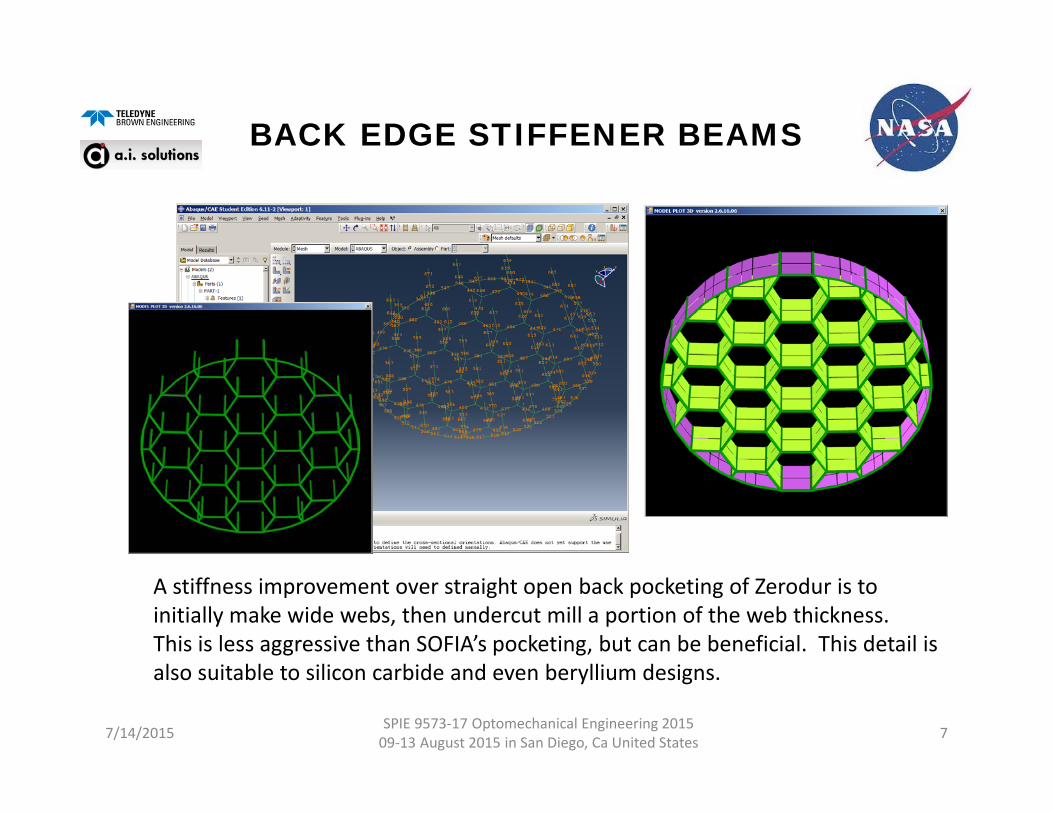
BACK EDGE STIFFENER BEAMS
7/14/2015 SPIE 9573‐17 Optomechanical Engineering 2015 09‐13 August 2015 in San Diego, Ca United States 7
A stiffness improvement over straight open back pocketing of Zerodur is to initially make wide webs, then undercut mill a portion of the web thickness. This is less aggressive than SOFIA’s pocketing, but can be beneficial. This detail is also suitable to silicon carbide and even beryllium designs.
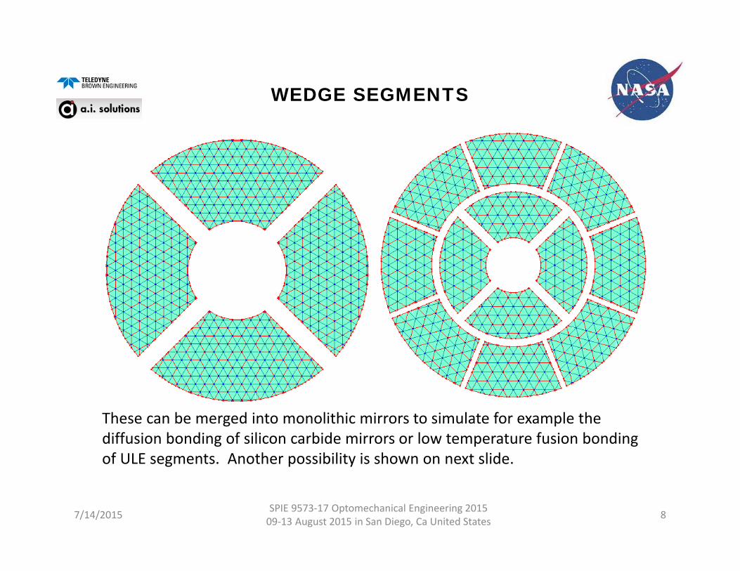
WEDGE SEGMENTS
7/14/2015 SPIE 9573‐17 Optomechanical Engineering 2015 09‐13 August 2015 in San Diego, Ca United States 8
These can be merged into monolithic mirrors to simulate for example the diffusion bonding of silicon carbide mirrors or low temperature fusion bonding of ULE segments. Another possibility is shown on next slide.
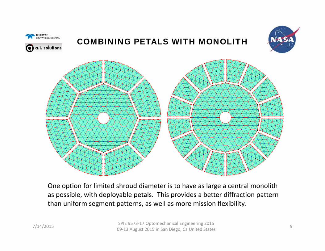
COMBINING PETALS WITH MONOLITH
7/14/2015 SPIE 9573‐17 Optomechanical Engineering 2015 09‐13 August 2015 in San Diego, Ca United States 9
One option for limited shroud diameter is to have as large a central monolith as possible, with deployable petals. This provides a better diffraction pattern than uniform segment patterns, as well as more mission flexibility.
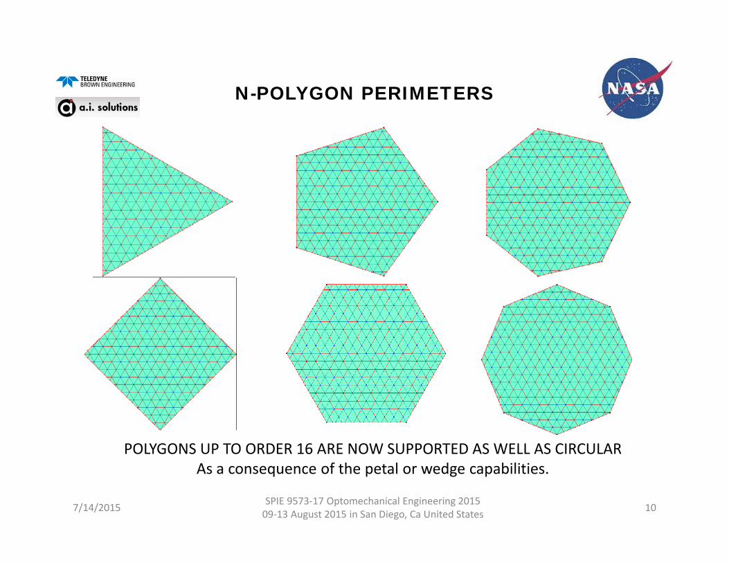
N-POLYGON PERIMETERS
7/14/2015 SPIE 9573‐17 Optomechanical Engineering 2015 09‐13 August 2015 in San Diego, Ca United States 10
POLYGONS UP TO ORDER 16 ARE NOW SUPPORTED AS WELL AS CIRCULARAs a consequence of the petal or wedge capabilities.
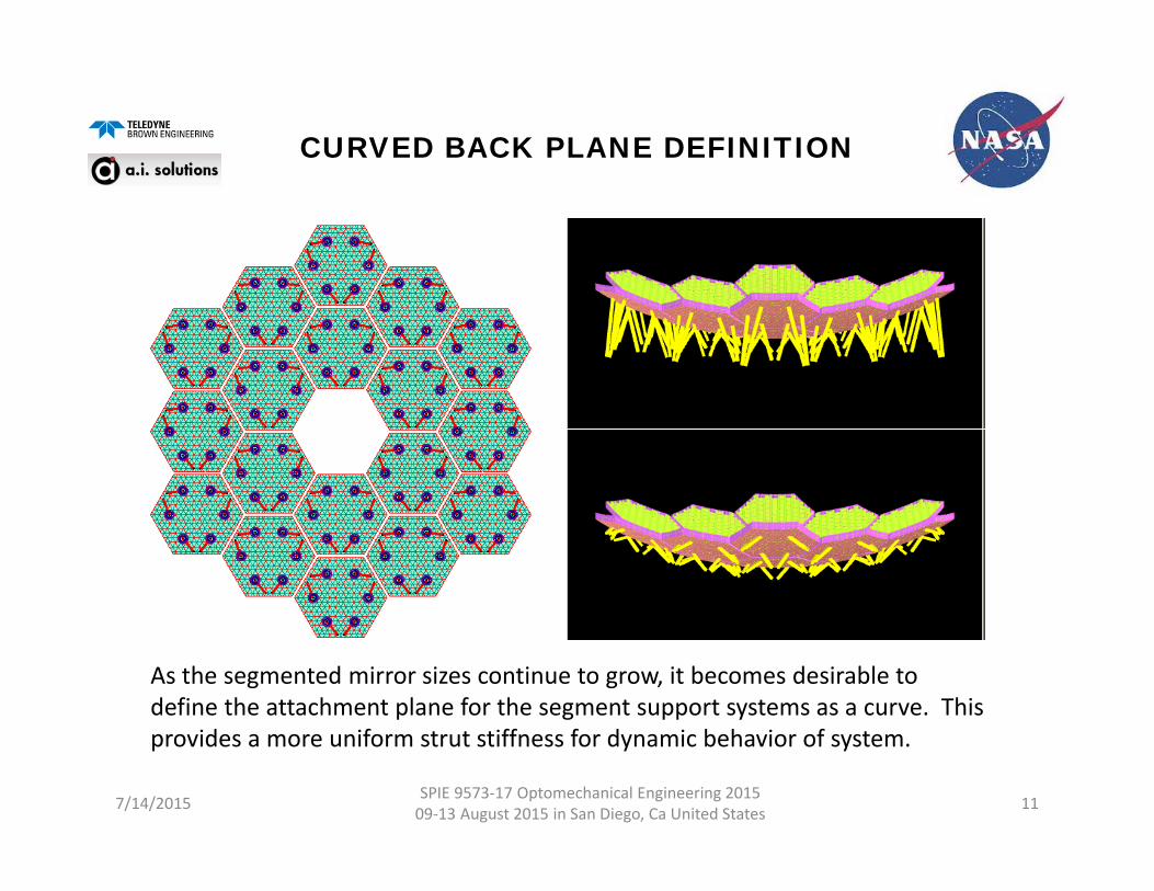
CURVED BACK PLANE DEFINITION
7/14/2015 SPIE 9573‐17 Optomechanical Engineering 2015 09‐13 August 2015 in San Diego, Ca United States 11
As the segmented mirror sizes continue to grow, it becomes desirable to define the attachment plane for the segment support systems as a curve. This provides a more uniform strut stiffness for dynamic behavior of system.
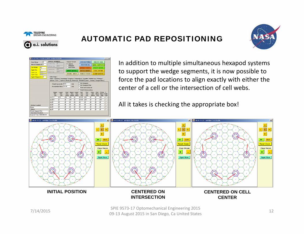
AUTOMATIC PAD REPOSITIONING
7/14/2015 SPIE 9573‐17 Optomechanical Engineering 2015 09‐13 August 2015 in San Diego, Ca United States 12
INITIAL POSITION CENTERED ON INTERSECTION
CENTERED ON CELL CENTER
In addition to multiple simultaneous hexapod systems to support the wedge segments, it is now possible to force the pad locations to align exactly with either the center of a cell or the intersection of cell webs.
All it takes is checking the appropriate box!

OFF-AXIS MIRRORS
7/14/2015 SPIE 9573‐17 Optomechanical Engineering 2015 09‐13 August 2015 in San Diego, Ca United States 13
With the emergence of interest in space‐based UV optics, the diffraction advantages of off‐axis systems, particularly monolithic primary based has spurred the development of the ability to create off‐axis models.
WHERE ARE WE GOING FROM HERE?
• INITIAL PUBLICATION/RELEASE OF THE SOFTWARE IS PLANNED FOR SEPTEMBER 2015.
• CURRENTLY THE DISTRIBUTION OF THE PROGRAM IS EXPORT ADMINISTRATION REGULATIONS RESTRICTED TO US CITIZENS AND US ENTITIES.
• INTEGRATION OF THE OUTPUT FILE FORMATS WITH THE OPTICAL PERFORMANCE ANALYSIS SYSTEMS UNDER DEVELOPMENT FOR AMTD.
• IMPROVED BOND PAD MODELING TO INCLUDE GLUE LAYER AND ACTUAL PAD GEOMETRY (1ST ORDER DETAIL ONLY)
7/14/2015 SPIE 9573‐17 Optomechanical Engineering 2015 09‐13 August 2015 in San Diego, Ca United States 14
ACKNOWLEDGEMENTS
• This work has been supported by the AMTD project and Dr. H. Phil Stahl and the staff of ES31, ES22 and VP10 at Marshall Space Fight Center, Huntsville, Alabama.
• A number of NASA interns have made major contributions to the development of the program, through their tireless efforts to break the code during testing and creative interruptions of the user’s manual under development.
• Jacob Vehonsky• Ryan M. Bevins• Matthew Fitzgerald• Rubin Jaca Rosa• Erik Humfleet
7/14/2015 SPIE 9573‐17 Optomechanical Engineering 2015 09‐13 August 2015 in San Diego, Ca United States 15

REFERENCES
7/14/2015 SPIE 9573‐17 Optomechanical Engineering 2015 09‐13 August 2015 in San Diego, Ca United States 16
1. Arnold, W. R., “AMTD DESIGN PROCESS”, NASA/SPIE MirrorTechnology Days 2014, Albuquerque, NM (2014)
2. Arnold, W. R., “Arnold Mirror Modeler Demonstration Video (30 min)”,NASA/SPIE Mirror Technology Days 2014, Albuquerque, NM (2014)
3. Arnold, W. R., Etal., “Next-generation lightweight mirror modelingsoftware”, SPIE Opto-mechanical Engineering 2013, San Diego, CA SPIE8836-15 (2013)
4. Arnold, W. R., Etal., “Integration of mirror design with suspension systemusing NASA’s new mirror modeling software”, SPIE Opto-mechanicalEngineering 2013, San Diego, CA SPIE 8836-17 (2013)
5. Arnold, W. R., Etal. “Next-generation lightweight mirror modeling software”,NASA Mirror Tech Days 2013, Redondo Beach, CA (2013)