Embed Size (px)
Citation preview
Sun Hydraulics Technical Tips
1 · Tech Tips:Web# 999-901-363 Rev. 10SEP13 © 2013 Sun Hydraulics Corporation
Reducing and Reducing/Relieving Valves
APPLICATIONS
Reducing Cartridges
Reducing cartridges are normally open pressure control elements designed to reduce a high primary pressure at port 2 (inlet) to a controlled lower pressure (reduced pressure) at port 1 (outlet). The reduced pressure is determined by the spring adjustment plus any pressure at port 3 (adjustment spring chamber drain).
Reducing/Relieving Cartridges
Reducing/relieving cartridges add the function of a full flow pressure relief valve from the reduced pressure port 1 to drain/tank port 3. This feature allows the reduced pressure at port 1 to remain relatively constant under back flow conditions.
A typical application would be to provide a controlled lower pressure to a secondary circuit function (reducing and/or reducing/relieving valves).
A reducing valve can provide accurate pressure in clamp and hold down circuits.
Another application would be to use a reducing/relieving valve to provide a constant pressure as a counterbalancing force for bi-directional machine elements.
Even though Sun reducing and reducing/relieving valves are normally open devices, full reverse free flow may close the main spool. The reverse flow function can be accom-plished by adding a separate reverse flow check valve. In a non-deadheaded application (or where a directional valve
with an open center crossover condition is present), the drain port 3 can be connected to the opposite actuator line, allowing system pressure in the adjustment spring chamber to hold the valve open. However, return flow capacity will be limited by the main stage bias spring.
A reducing valve can also function as an adjustable restric-tive pressure compensator. (See Figure 1.)
All Sun pilot operated reducing and reducing/relieving cartridges incorporate a 150 micron stainless steel screen to protect the orifice from contamination.
Sun Hydraulics’ reducing and reducing/relieving valves have flow capacities of 5 to 80 gpm (20-320 L/min) and are all fully adjustable over a range of operating pressures up to 4500 psi (315 bar) with inlet pressures up 5000 psi (350 bar). (Air piloted versions have a lower pressure range; up to 1500 psi [107 bar] with a maximum inlet pressure of 3000 psi [210 bar].) Prior to shipping, all Sun reducing and reducing/relieving valves are factory pressure set at deadhead condition except for direct acting reducers which are set with a flow of 2 in3/min (30 cc/min), because they have no pilot flow. NOTE: All Sun reducing and reducing/relieving cartridges are functionally interchangeable (i.e. same flow path and same cavities for a given frame size). However, with reducing/relieving valves, it is important that the port 3 (adjustment spring chamber drain) connection is sized as a full capacity return passage.
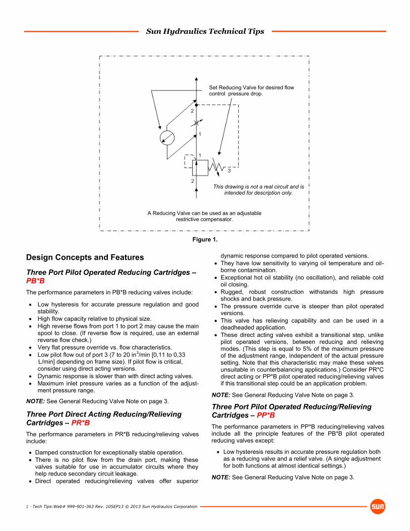
This drawing is not a real circuit and is intended for description only.
Use reducing valves in closed center circuits to provide a lower pressure to a second circuit.
Use reducing/relieving valves to provide a controlled lower pressure on one side of ex-tending/reversing cylinders (counterbalancing).
Use reducing valves with a reverse flow check to provide a lower pressure in one direction with no effect on pressure in the other direction.
Sun Hydraulics Technical Tips
2 · Tech Tips:Web# 999-901-363 Rev. 10SEP13 © 2013 Sun Hydraulics Corporation
Design Concepts and Features
Three Port Pilot Operated Reducing Cartridges – PB*B
The performance parameters in PB*B reducing valves include:
Low hysteresis for accurate pressure regulation and good stability.
High flow capacity relative to physical size.
High reverse flows from port 1 to port 2 may cause the main spool to close. (If reverse flow is required, use an external reverse flow check.)
Very flat pressure override vs. flow characteristics.
Low pilot flow out of port 3 (7 to 20 in3/min [0,11 to 0,33 L/min] depending on frame size). If pilot flow is critical, consider using direct acting versions.
Dynamic response is slower than with direct acting valves.
Maximum inlet pressure varies as a function of the adjust-ment pressure range.
NOTE: See General Reducing Valve Note on page 3.
Three Port Direct Acting Reducing/Relieving Cartridges – PR*B
The performance parameters in PR*B reducing/relieving valves include:
Damped construction for exceptionally stable operation.
There is no pilot flow from the drain port, making these valves suitable for use in accumulator circuits where they help reduce secondary circuit leakage.
Direct operated reducing/relieving valves offer superior
dynamic response compared to pilot operated versions.
They have low sensitivity to varying oil temperature and oil-borne contamination.
Exceptional hot oil stability (no oscillation), and reliable cold oil closing.
Rugged, robust construction withstands high pressure shocks and back pressure.
The pressure override curve is steeper than pilot operated versions.
This valve has relieving capability and can be used in a deadheaded application.
These direct acting valves exhibit a transitional step, unlike pilot operated versions, between reducing and relieving modes. (This step is equal to 5% of the maximum pressure of the adjustment range, independent of the actual pressure setting. Note that this characteristic may make these valves unsuitable in counterbalancing applications.) Consider PR*C direct acting or PP*B pilot operated reducing/relieving valves if this transitional step could be an application problem.
NOTE: See General Reducing Valve Note on page 3.
Three Port Pilot Operated Reducing/Relieving Cartridges – PP*B
The performance parameters in PP*B reducing/relieving valves include all the principle features of the PB*B pilot operated reducing valves except:
Low hysteresis results in accurate pressure regulation both as a reducing valve and a relief valve. (A single adjustment for both functions at almost identical settings.)
NOTE: See General Reducing Valve Note on page 3.
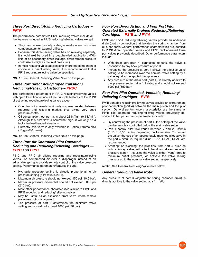
This drawing is not a real circuit and is intended for description only.
Set Reducing Valve for desired flow control pressure drop.
A Reducing Valve can be used as an adjustable restrictive compensator.
Figure 1.
Sun Hydraulics Technical Tips
3 · Tech Tips:Web# 999-901-363 Rev. 10SEP13 © 2013 Sun Hydraulics Corporation
Three Port Direct Acting Reducing Cartridges – PR*R
The performance parameters PR*R reducing valves include all the features included in PR*B reducing/relieving valves except:
They can be used as adjustable, normally open, restrictive compensators for external orifices.
Because this direct acting valve has no relieving capability, it should not be used in a deadheaded application. (With little or no secondary circuit leakage, down stream pressure could rise as high as the inlet pressure.)
In most reducing valve applications where the component of choice is a direct acting valve, it is recommended that a PR*B reducing/relieving valve be specified.
NOTE: See General Reducing Valve Note on this page.
Three Port Direct Acting (open transition)Reducing/Relieving Cartridge – PRDC
The performance parameters in PR*C reducing/relieving valves with open transition include all the principle features of the PR*B direct acting reducing/relieving valves except:
Open transition results in virtually no pressure step between reducing and relieving modes, thus giving very good pressure control.
Oil consumption, out port 3, is about 23 in3/min (0,4 L/min). Although this pilot flow is somewhat high, it will only be a factor in deadheaded situations.
Currently, this valve is only available in Series 1 frame size (10 gpm/40 L/min).
NOTE: See General Reducing Valve Note on this page.
Three Port Air Controlled Pilot Operated Reducing and Reducing/Relieving Cartridges — PB*C and PP*C
PB*C and PP*C air piloted reducing and reducing/relieving valves use compressed air over a diaphragm instead of an adjustable spring to provide remote control of the valve pressure setting. Performance parameters/features include:
Hydraulic pressure setting is directly proportional to air pressure setting (pilot ratio is 20:1).
Maximum air pressure should not exceed 150 psi (10,5 bar).
Maximum pressure differential should not exceed 3000 psi (210 bar).
Most other performance characteristics similar to PB*B and PP*B reducing and reducing/relieving valves.
May be useful as an explosion proof valve where remote pressure control is required.
The pressure at port 3 determines the minimum valve setting and should not exceed 1000 psi (70 bar).
Four Port Direct Acting and Four Port Pilot Operated Externally Drained Reducing/Relieving Cartridges— PS*B and PV*A
PS*B and PV*A reducing/relieving valves provide an additional drain (port 4) connection that isolates the spring chamber from all other ports. General performance characteristics are identical to PR*B direct operated valves and PP*B pilot operated three port valves previously described. Other performance parameters include:
With drain port (port 4) connected to tank, the valve is insensitive to any back pressure at port 3.
Increasing the pressure at port 4 allows the effective valve setting to be increased over the nominal valve setting by a value equal to the applied backpressure.
Any pressure at the drain port (port 4), is directly additive to the pressure setting at a 1:1 ratio, and should not exceed 5000 psi (350 bar).
Four Port Pilot Operated, Ventable, Reducing/Relieving Cartridges – PV*B
PV*B ventable reducing/relieving valves provide an extra remote pilot connection (port 4) between the main piston and the pilot section. General performance characteristics are the same as PP*B pilot operated reducing/relieving valves previously de-scribed. Other performance parameters include:
By controlling the pressure at port 4, the setting of the valve can be remotely controlled below the main valve setting.
Port 4 control pilot flow varies between 7 and 20 in3/min (0,11 to 0,33 L/min), depending on frame size. To control the valve, the use of an appropriately matched pilot valve in the port 4 circuit is required (Sun RBAA, RBAC, RBAD are recommended).
“Venting” or “blocking” the pilot flow from port 4, such as with a 2-way valve, will affect the down stream reduced pressure at port 1, causing the valve to either “vent” (drop to minimum outlet pressure) or activate the valve raising pressure up to the nominal valve setting, respectively.
NOTE: See General Reducing Valve note below.
General Reducing Valve Note:
Any pressure at port 3 (adjustment spring chamber drain) is directly additive to the valve setting at a 1:1 ratio.
Sun Hydraulics Technical Tips
4 · Tech Tips:Web# 999-901-363 Rev. 10SEP13 © 2013 Sun Hydraulics Corporation
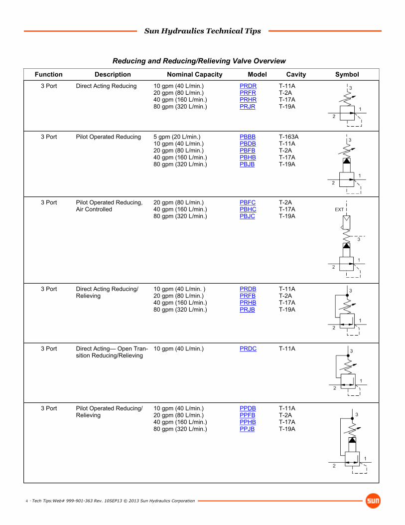
Function Description Nominal Capacity Model Cavity Symbol
3 Port Direct Acting Reducing 10 gpm (40 L/min.) 20 gpm (80 L/min.) 40 gpm (160 L/min.) 80 gpm (320 L/min.)
PRDR PRFR PRHR PRJR
T-11A T-2A T-17A T-19A
3 Port Pilot Operated Reducing 5 gpm (20 L/min.) 10 gpm (40 L/min.) 20 gpm (80 L/min.) 40 gpm (160 L/min.) 80 gpm (320 L/min.)
PBBB PBDB PBFB PBHB PBJB
T-163A T-11A T-2A T-17A T-19A
3 Port Pilot Operated Reducing, Air Controlled
20 gpm (80 L/min.) 40 gpm (160 L/min.) 80 gpm (320 L/min.)
PBFC PBHC PBJC
T-2A T-17A T-19A
3 Port Direct Acting Reducing/Relieving
10 gpm (40 L/min. ) 20 gpm (80 L/min.) 40 gpm (160 L/min.) 80 gpm (320 L/min.)
PRDB PRFB PRHB PRJB
T-11A T-2A T-17A T-19A
3 Port Direct Acting— Open Tran-sition Reducing/Relieving
10 gpm (40 L/min.)
PRDC T-11A
3 Port Pilot Operated Reducing/Relieving
10 gpm (40 L/min.) 20 gpm (80 L/min.) 40 gpm (160 L/min.) 80 gpm (320 L/min.)
PPDB PPFB PPHB PPJB
T-11A T-2A T-17A T-19A
Reducing and Reducing/Relieving Valve Overview
Sun Hydraulics Technical Tips
5 · Tech Tips:Web# 999-901-363 Rev. 10SEP13 © 2013 Sun Hydraulics Corporation
Function Description Nominal Capacity Model Cavity Symbol
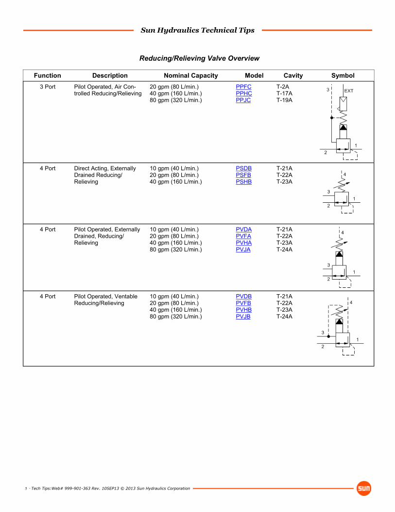
3 Port Pilot Operated, Air Con-trolled Reducing/Relieving
20 gpm (80 L/min.) 40 gpm (160 L/min.) 80 gpm (320 L/min.)
PPFC PPHC PPJC
T-2A T-17A T-19A
4 Port Direct Acting, Externally Drained Reducing/Relieving
10 gpm (40 L/min.) 20 gpm (80 L/min.) 40 gpm (160 L/min.)
PSDB PSFB PSHB
T-21A T-22A T-23A
4 Port Pilot Operated, Externally Drained, Reducing/Relieving
10 gpm (40 L/min.) 20 gpm (80 L/min.) 40 gpm (160 L/min.) 80 gpm (320 L/min.)
PVDA PVFA PVHA PVJA
T-21A T-22A T-23A T-24A
4 Port Pilot Operated, Ventable Reducing/Relieving
10 gpm (40 L/min.) 20 gpm (80 L/min.) 40 gpm (160 L/min.) 80 gpm (320 L/min.)
PVDB PVFB PVHB PVJB
T-21A T-22A T-23A T-24A
Reducing/Relieving Valve Overview