Embed Size (px)
Citation preview
UNIS-FAGAS
UNIS-Factory of gas equipment Ltd.
Rajlovačka bb, 71000 SARAJEVO
Tel.: +387 33 590 739 Fax.: +387 33 590 732
[email protected] | www.fagas.ba
REFERENCE LIST 2015
2
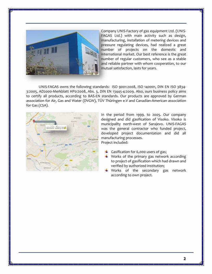
Company UNIS-Factory of gas equipment Ltd. (UNIS-FAGAS Ltd.) with main activity such as design, manufacturing, installation of metering devices and pressure regulating devices, had realized a great number of projects on the domestic and international market. Our best reference is the great number of regular customers, who see as a stable and reliable partner with whom cooperation, to our mutual satisfaction, lasts for years.
UNIS-FAGAS owns the following standards: ISO 9001:2008, ISO 140001, DIN EN ISO 3834-
3:2005, AD2000-Merkblatt HP0:2008, Abs. 3, DIN EN 13445-4:2009. Also, ours business policy aims to certify all products, according to BAS-EN standards. Our products are approved by German association for Air, Gas and Water (DVGW), TÜV Thüringen e.V and Canadian-American association for Gas (CSA).
In the period from 1999. to 2005. Our company designed and did gasification of Visoko. Visoko is municipality north-west of Sarajevo. UNIS-FAGAS was the general contractor who funded project, developed project documentation and did all manufacturing processes. Project included:
Gasification for 6,000 users of gas; Works of the primary gas network according
to project of gasification which had drawn and verified by authorized institution;
Works of the secondary gas network according to own project.
3
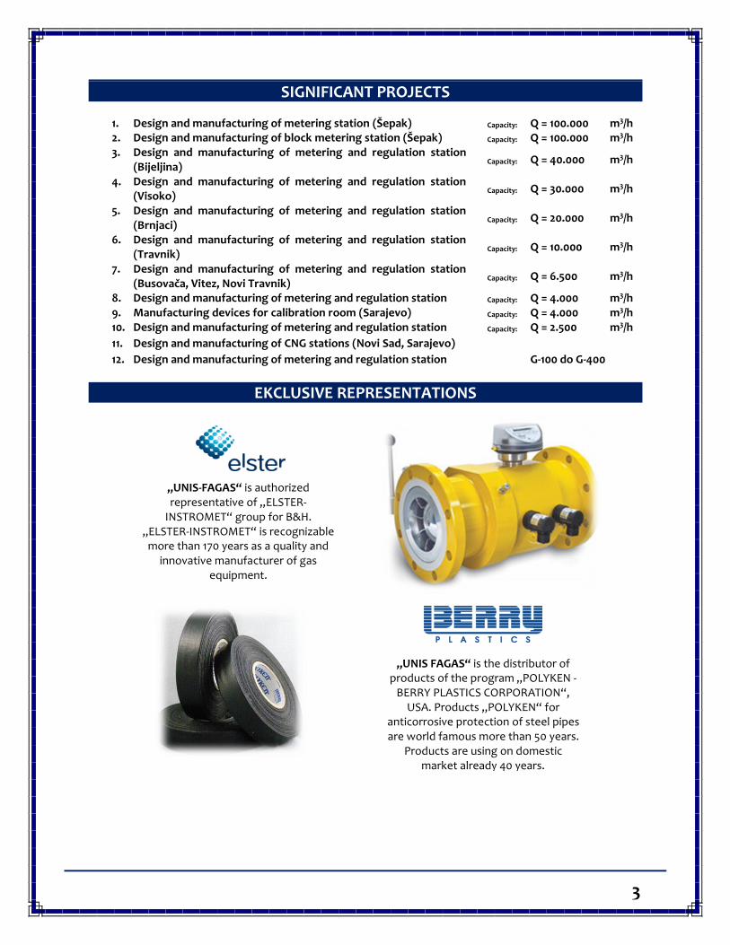
SIGNIFICANT PROJECTS
1. Design and manufacturing of metering station (Šepak) Capacity: Q = 100.000 m3/h 2. Design and manufacturing of block metering station (Šepak) Capacity: Q = 100.000 m3/h 3. Design and manufacturing of metering and regulation station
(Bijeljina) Capacity: Q = 40.000 m3/h
4. Design and manufacturing of metering and regulation station (Visoko)
Capacity: Q = 30.000 m3/h
5. Design and manufacturing of metering and regulation station (Brnjaci)
Capacity: Q = 20.000 m3/h
6. Design and manufacturing of metering and regulation station (Travnik)
Capacity: Q = 10.000 m3/h
7. Design and manufacturing of metering and regulation station (Busovača, Vitez, Novi Travnik)
Capacity: Q = 6.500 m3/h
8. Design and manufacturing of metering and regulation station Capacity: Q = 4.000 m3/h 9. Manufacturing devices for calibration room (Sarajevo) Capacity: Q = 4.000 m3/h 10. Design and manufacturing of metering and regulation station Capacity: Q = 2.500 m3/h 11. Design and manufacturing of CNG stations (Novi Sad, Sarajevo) 12. Design and manufacturing of metering and regulation station G-100 do G-400
EKCLUSIVE REPRESENTATIONS
„UNIS-FAGAS“ is authorized representative of „ELSTER-
INSTROMET“ group for B&H. „ELSTER-INSTROMET“ is recognizable
more than 170 years as a quality and innovative manufacturer of gas
equipment.
„UNIS FAGAS“ is the distributor of products of the program „POLYKEN -
BERRY PLASTICS CORPORATION“, USA. Products „POLYKEN“ for
anticorrosive protection of steel pipes are world famous more than 50 years.
Products are using on domestic market already 40 years.
4
„UNIS FAGAS“ is representative of „PREMATLAK“ company for B&H, that
manufactures manometers and thermometers. UNIS FAGAS owns type
approval for manometers and thermometers issued by „INSTITUTE
FOR METROLOGY“, B&H.
„UNIS FAGAS“ is authorized representative of
„TECHART“ company for B&H. Company „TECHART“ is specialized for
electrochemical protection of steel from corrosion. Applying
„TECHART“ solutions completely stops corrosion and extends lifetime
of equipment for decades.
5
DELIVERY AND INSTALLATION OF EQUIPMENT FOR TELEMETRY SYSTEM
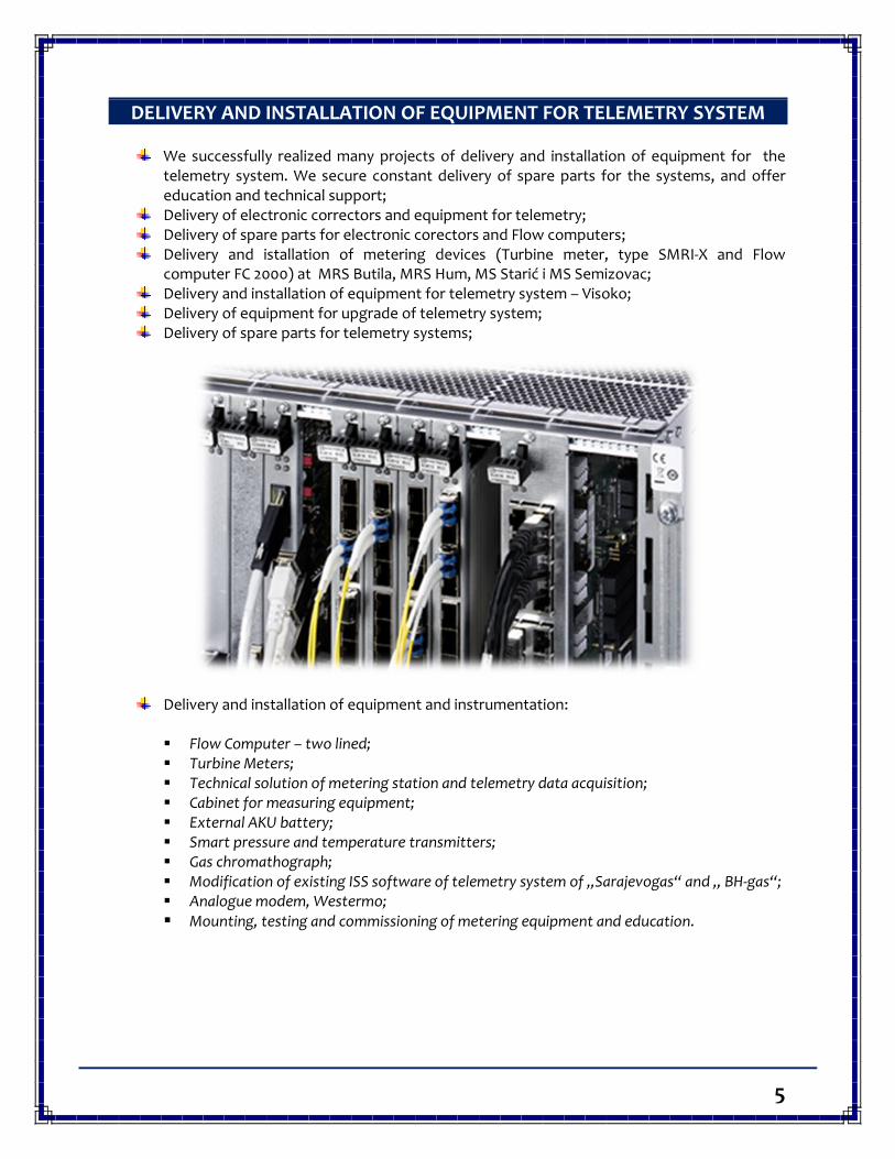
We successfully realized many projects of delivery and installation of equipment for the telemetry system. We secure constant delivery of spare parts for the systems, and offer education and technical support;
Delivery of electronic correctors and equipment for telemetry; Delivery of spare parts for electronic corectors and Flow computers; Delivery and istallation of metering devices (Turbine meter, type SMRI-X and Flow
computer FC 2000) at MRS Butila, MRS Hum, MS Starić i MS Semizovac; Delivery and installation of equipment for telemetry system – Visoko; Delivery of equipment for upgrade of telemetry system; Delivery of spare parts for telemetry systems;
Delivery and installation of equipment and instrumentation:
Flow Computer – two lined; Turbine Meters; Technical solution of metering station and telemetry data acquisition; Cabinet for measuring equipment; External AKU battery; Smart pressure and temperature transmitters; Gas chromathograph; Modification of existing ISS software of telemetry system of „Sarajevogas“ and „ BH-gas“; Analogue modem, Westermo; Mounting, testing and commissioning of metering equipment and education.
6
PHOTO REFERENCES PRODUCTION YEAR: 2012. / 2013. / 2014. / 2015.
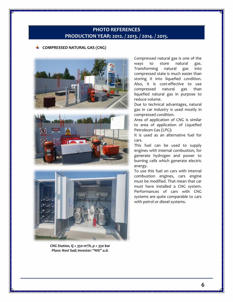
COMPRESSED NATURAL GAS (CNG)
Compressed natural gas is one of the ways to store natural gas. Transforming natural gas into compressed state is much easier than storing it into liquefied condition. Also, it is cost-effective to use compressed natural gas than liquefied natural gas in purpose to reduce volume. Due to technical advantages, natural gas in car industry is used mostly in compressed condition. Area of application of CNG is similar to area of application of Liquefied Petroleum Gas (LPG): It is used as an alternative fuel for cars. This fuel can be used to supply engines with internal combustion, for generate hydrogen and power to burning cells which generate electric energy. To use this fuel on cars with internal combustion engines, cars engine must be modified. That mean that car must have installed a CNG system. Performances of cars with CNG systems are quite comparable to cars with petrol or diesel systems.
CNG Station, Q = 350 m3/h, p = 350 bar Place: Novi Sad; Investor: “NIS” a.d.
7
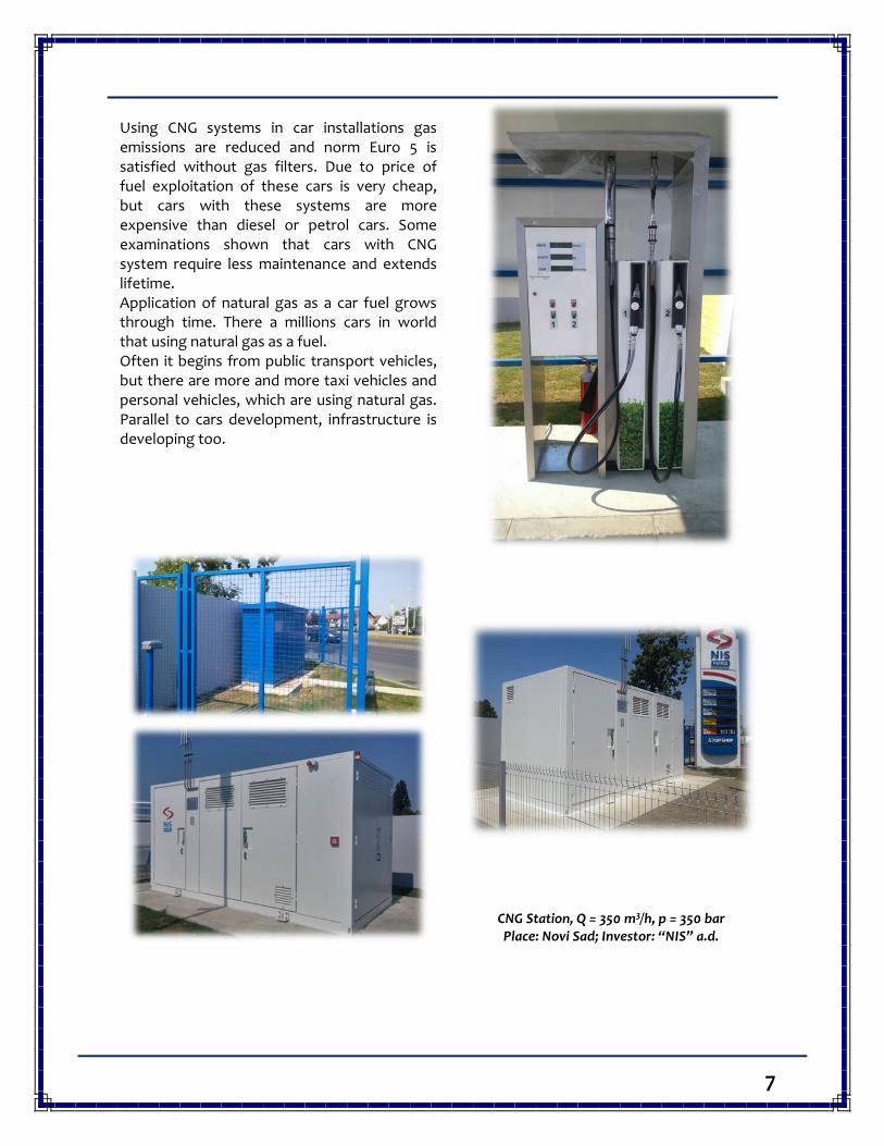
Using CNG systems in car installations gas emissions are reduced and norm Euro 5 is satisfied without gas filters. Due to price of fuel exploitation of these cars is very cheap, but cars with these systems are more expensive than diesel or petrol cars. Some examinations shown that cars with CNG system require less maintenance and extends lifetime. Application of natural gas as a car fuel grows through time. There a millions cars in world that using natural gas as a fuel. Often it begins from public transport vehicles, but there are more and more taxi vehicles and personal vehicles, which are using natural gas. Parallel to cars development, infrastructure is developing too.
CNG Station, Q = 350 m3/h, p = 350 bar Place: Novi Sad; Investor: “NIS” a.d.
8
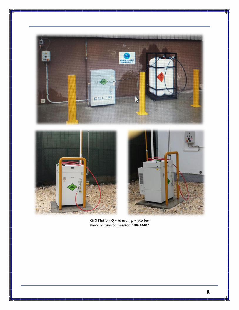
CNG Station, Q = 10 m3/h, p = 350 bar Place: Sarajevo; Investor: “BIHAMK”
9
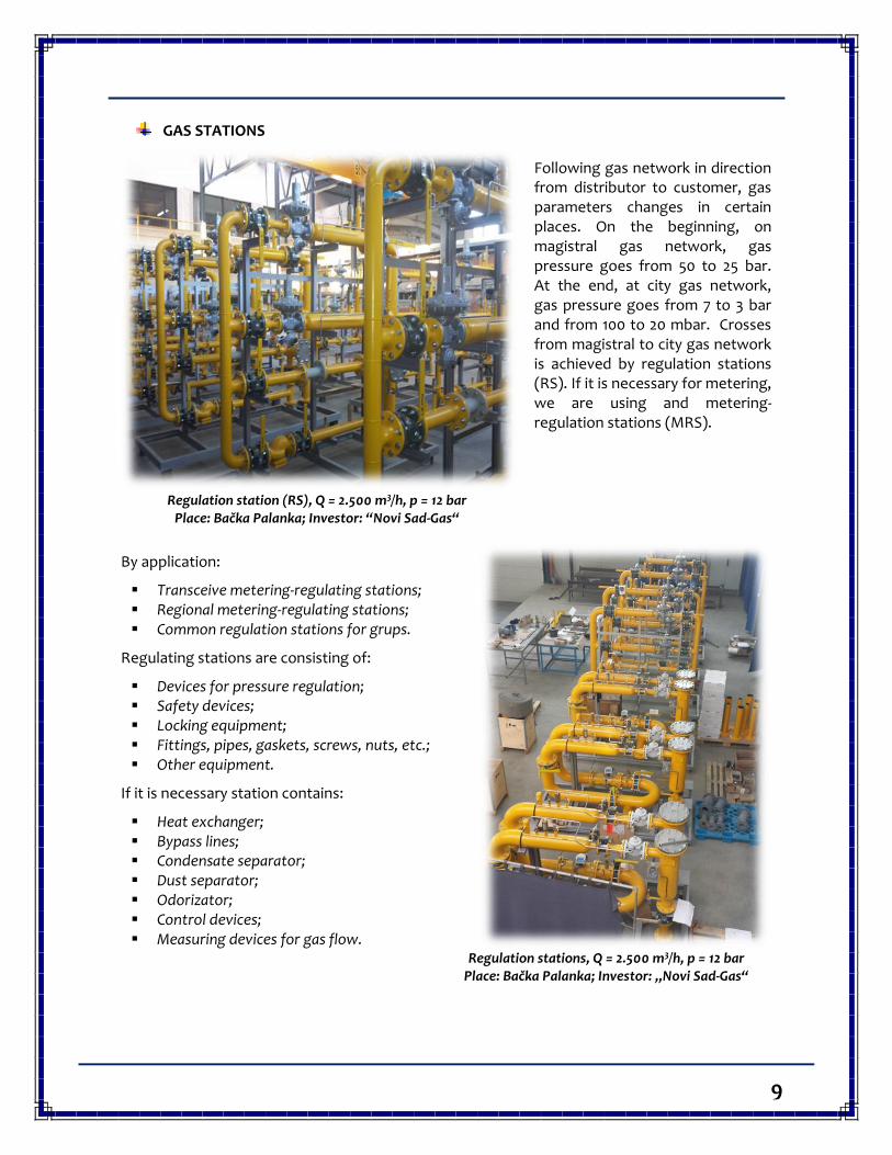
GAS STATIONS
Following gas network in direction from distributor to customer, gas parameters changes in certain places. On the beginning, on magistral gas network, gas pressure goes from 50 to 25 bar. At the end, at city gas network, gas pressure goes from 7 to 3 bar and from 100 to 20 mbar. Crosses from magistral to city gas network is achieved by regulation stations (RS). If it is necessary for metering, we are using and metering-regulation stations (MRS).
Regulation station (RS), Q = 2.500 m3/h, p = 12 bar
Place: Bačka Palanka; Investor: “Novi Sad-Gas“
By application:
Transceive metering-regulating stations; Regional metering-regulating stations; Common regulation stations for grups.
Regulating stations are consisting of:
Devices for pressure regulation; Safety devices; Locking equipment; Fittings, pipes, gaskets, screws, nuts, etc.; Other equipment.
If it is necessary station contains:
Heat exchanger; Bypass lines; Condensate separator; Dust separator; Odorizator; Control devices; Measuring devices for gas flow.
Regulation stations, Q = 2.500 m3/h, p = 12 bar
Place: Bačka Palanka; Investor: „Novi Sad-Gas“
10
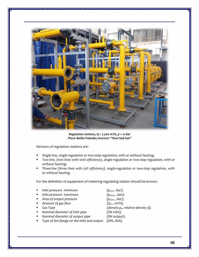
Regulation stations, Q = 2.500 m3/h, p = 12 bar
Place: Bačka Palanka; Investor: “Novi Sad-Gas“
Versions of regulation stations are:
Single-line, single-regulation or two-step regulation, with or without heating; Two-line, (two lines with 100% efficiency), single-regulation or two-step regulation, with or
without heating; Three-line (three lines with 50% efficiency), single-regulation or two-step regulation, with
or without heating.
For the definition of equipment of metering-regulating station should be known:
Inlet pressure minimum (pimin , bar); Inlet pressure maximum (pumax , bar); Area of output pressure (podoz , bar); Amount of gas flow (Qvn , m3/h); Gas Type (density ρn, relative density d); Nominal diameter of inlet pipe (DN inlet); Nominal diameter of output pipe (DN output); Type of the flange on the inlet and output (DIN, ASA).
11
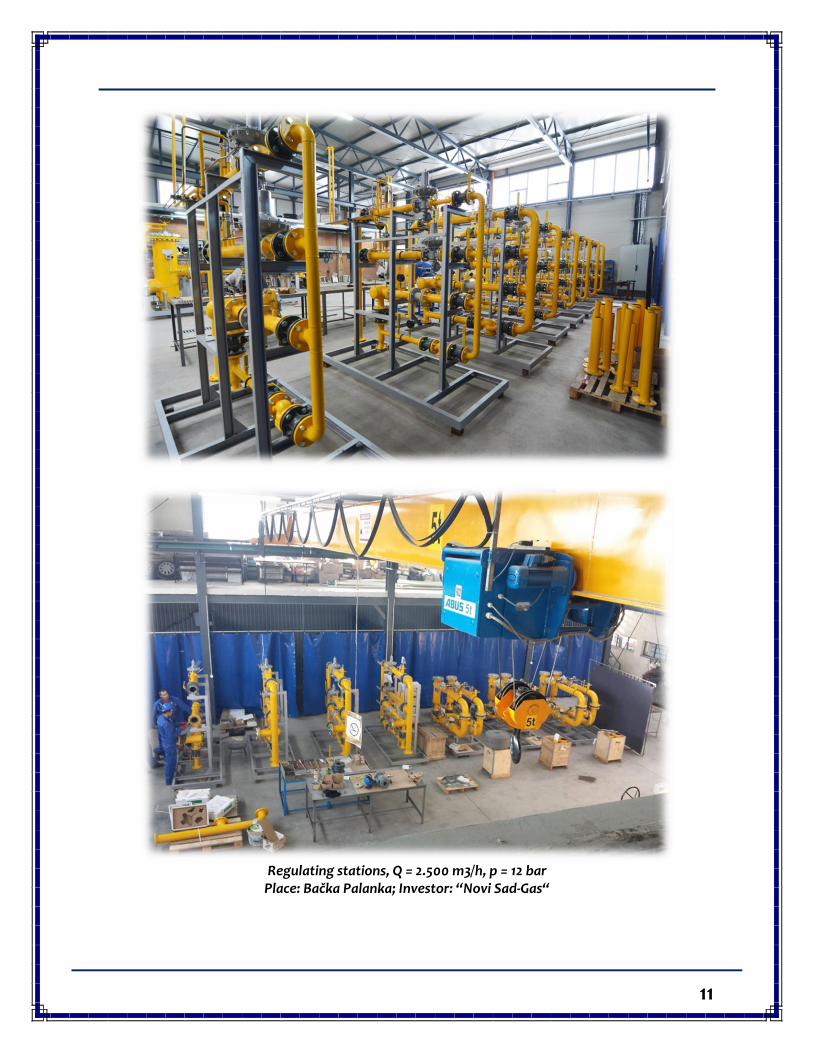
Regulating stations, Q = 2.500 m3/h, p = 12 bar
Place: Bačka Palanka; Investor: “Novi Sad-Gas“
12
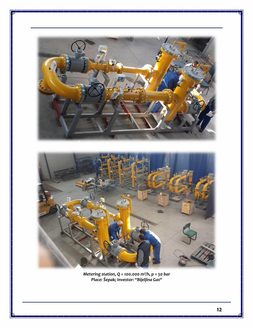
Metering station, Q = 100.000 m3/h, p = 50 bar
Place: Šepak; Investor: “Bijeljina Gas“
13
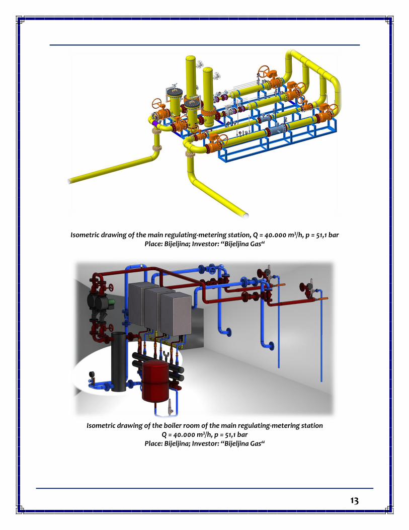
Isometric drawing of the main regulating-metering station, Q = 40.000 m3/h, p = 51,1 bar Place: Bijeljina; Investor: “Bijeljina Gas“
Isometric drawing of the boiler room of the main regulating-metering station
Q = 40.000 m3/h, p = 51,1 bar Place: Bijeljina; Investor: “Bijeljina Gas“
14
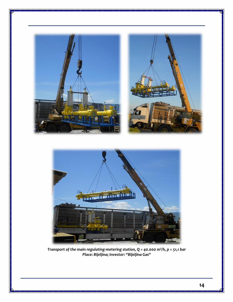
Transport of the main regulating-metering station, Q = 40.000 m3/h, p = 51,1 bar
Place: Bijeljina; Investor: “Bijeljina Gas“
15
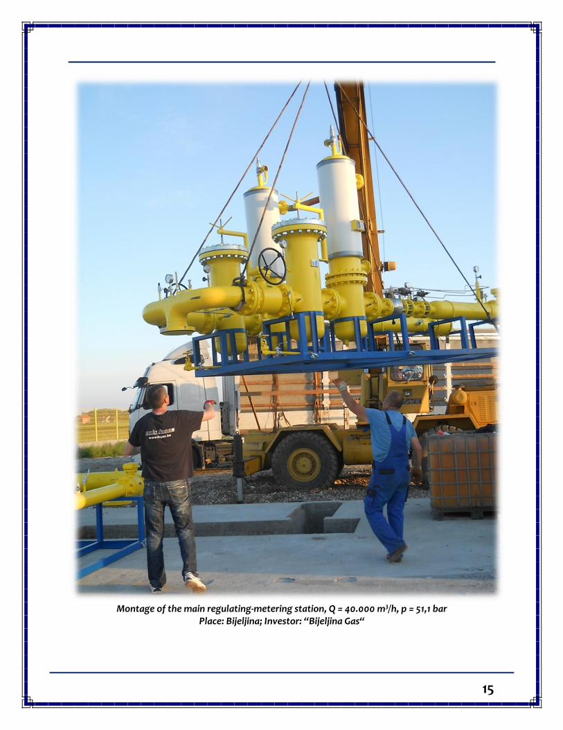
Montage of the main regulating-metering station, Q = 40.000 m3/h, p = 51,1 bar
Place: Bijeljina; Investor: “Bijeljina Gas“
16
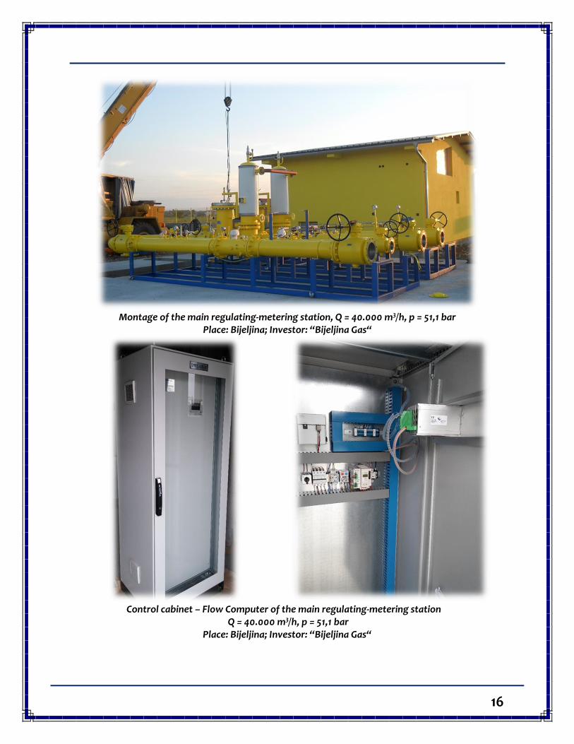
Montage of the main regulating-metering station, Q = 40.000 m3/h, p = 51,1 bar
Place: Bijeljina; Investor: “Bijeljina Gas“
Control cabinet – Flow Computer of the main regulating-metering station
Q = 40.000 m3/h, p = 51,1 bar Place: Bijeljina; Investor: “Bijeljina Gas“
17
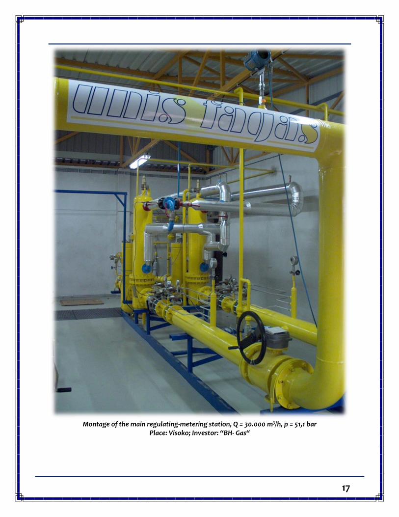
Montage of the main regulating-metering station, Q = 30.000 m3/h, p = 51,1 bar
Place: Visoko; Investor: “BH- Gas“
18
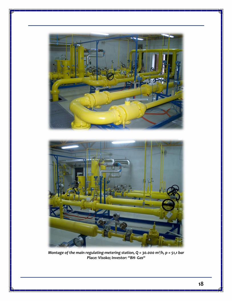
Montage of the main regulating-metering station, Q = 30.000 m3/h, p = 51,1 bar
Place: Visoko; Investor: “BH- Gas“
19
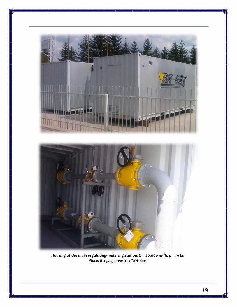
Housing of the main regulating-metering station, Q = 20.000 m3/h, p = 19 bar
Place: Brnjaci; Investor: “BH- Gas“
20
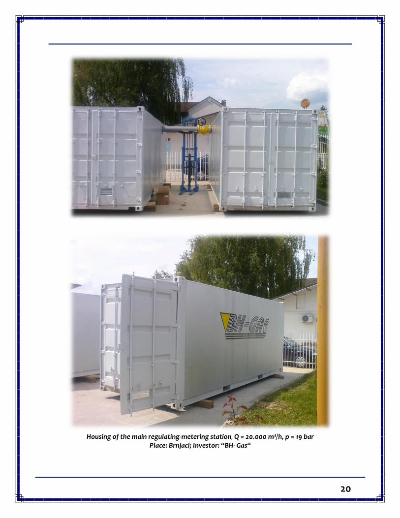
Housing of the main regulating-metering station, Q = 20.000 m3/h, p = 19 bar
Place: Brnjaci; Investor: “BH- Gas“
21
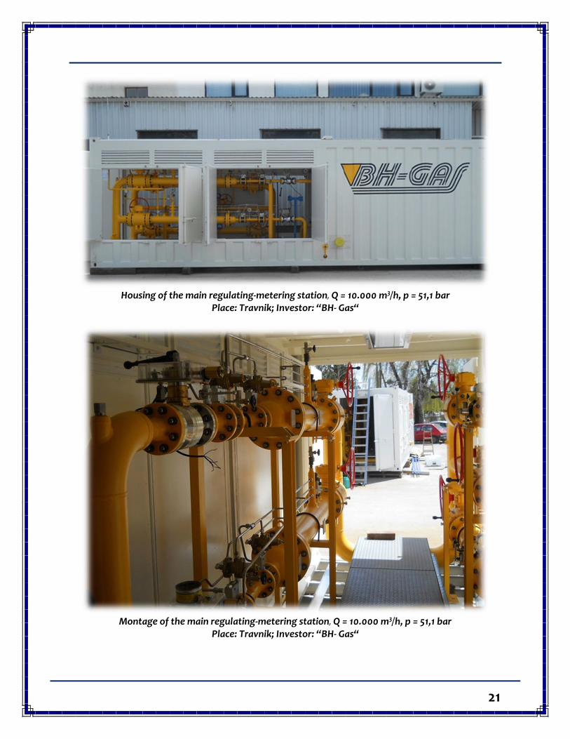
Housing of the main regulating-metering station, Q = 10.000 m3/h, p = 51,1 bar
Place: Travnik; Investor: “BH- Gas“
Montage of the main regulating-metering station, Q = 10.000 m3/h, p = 51,1 bar
Place: Travnik; Investor: “BH- Gas“
22
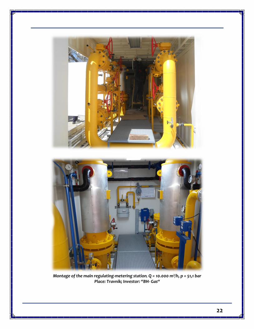
Montage of the main regulating-metering station, Q = 10.000 m3/h, p = 51,1 bar
Place: Travnik; Investor: “BH- Gas“
23
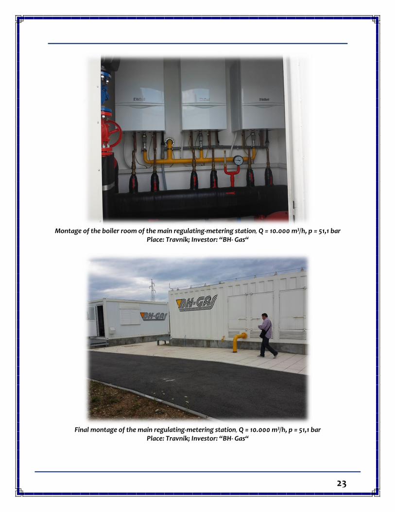
Montage of the boiler room of the main regulating-metering station, Q = 10.000 m3/h, p = 51,1 bar
Place: Travnik; Investor: “BH- Gas“
Final montage of the main regulating-metering station, Q = 10.000 m3/h, p = 51,1 bar
Place: Travnik; Investor: “BH- Gas“
24
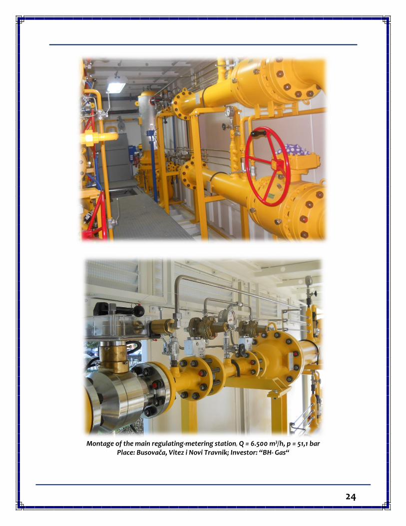
Montage of the main regulating-metering station, Q = 6.500 m3/h, p = 51,1 bar
Place: Busovača, Vitez i Novi Travnik; Investor: “BH- Gas“
25
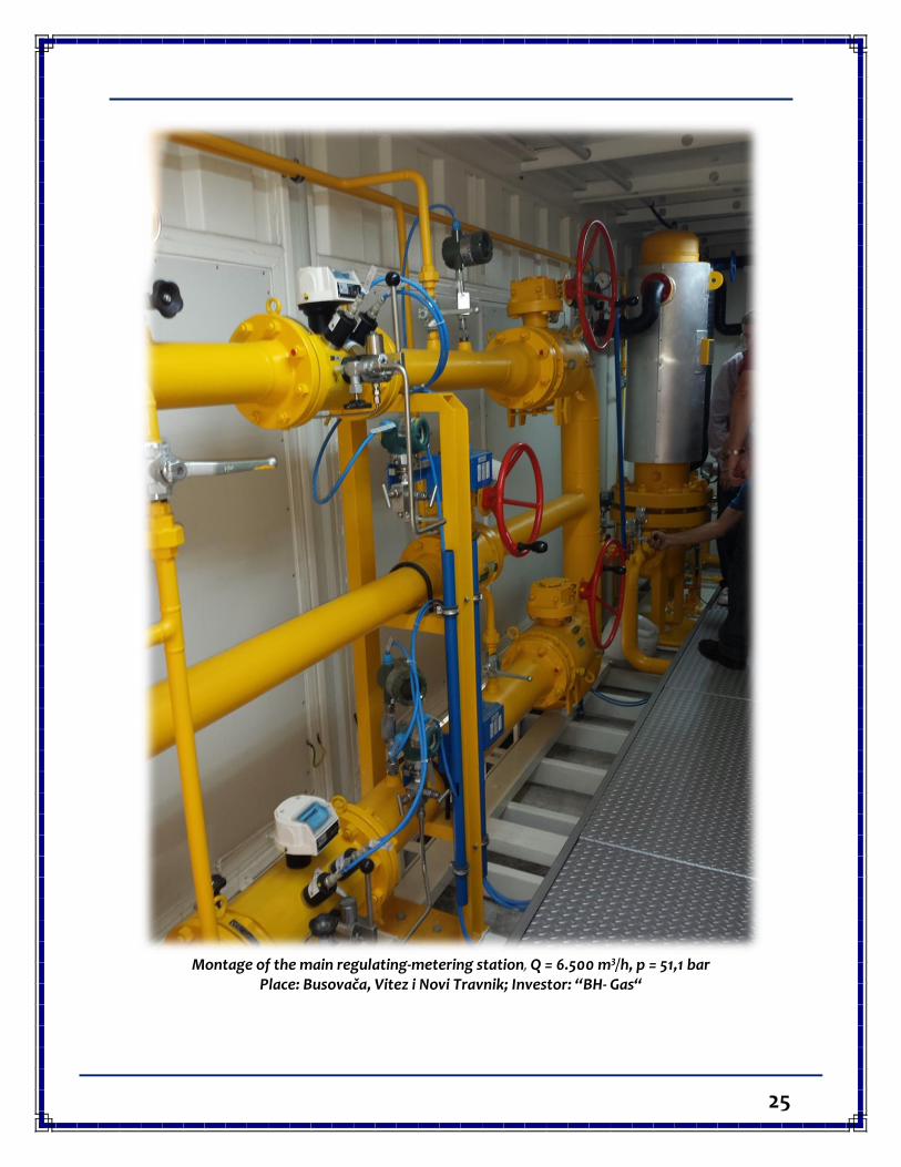
Montage of the main regulating-metering station, Q = 6.500 m3/h, p = 51,1 bar
Place: Busovača, Vitez i Novi Travnik; Investor: “BH- Gas“
26
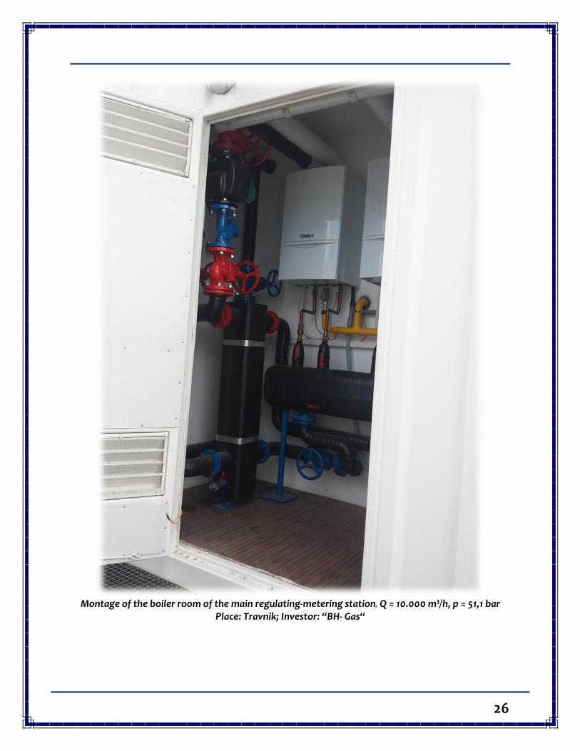
Montage of the boiler room of the main regulating-metering station, Q = 10.000 m3/h, p = 51,1 bar
Place: Travnik; Investor: “BH- Gas“
27
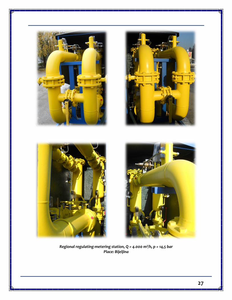
Regional regulating-metering station, Q = 4.000 m3/h, p = 14,5 bar Place: Bijeljina
28
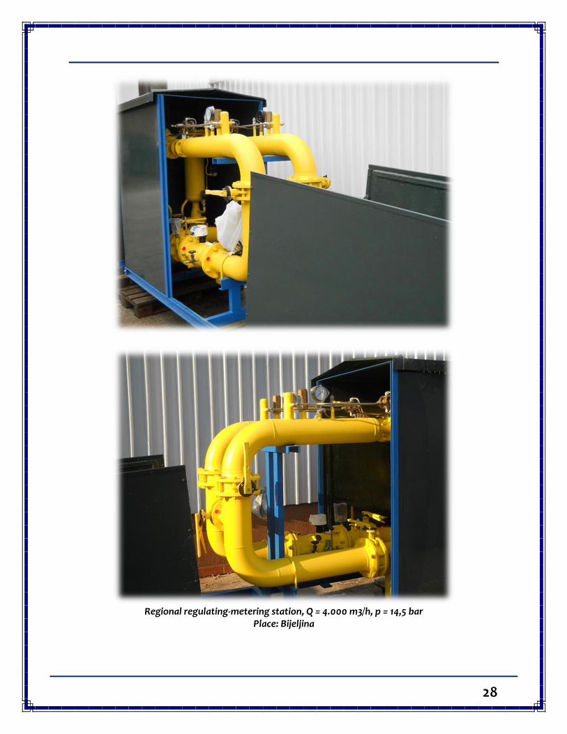
Regional regulating-metering station, Q = 4.000 m3/h, p = 14,5 bar
Place: Bijeljina
29
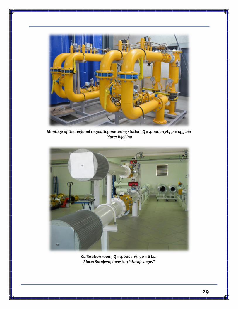
Montage of the regional regulating-metering station, Q = 4.000 m3/h, p = 14,5 bar
Place: Bijeljina
Calibration room, Q = 4.000 m3/h, p = 6 bar
Place: Sarajevo; Investor: “Sarajevogas“
30
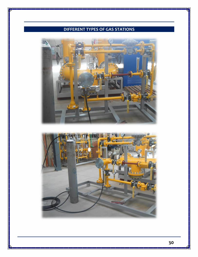
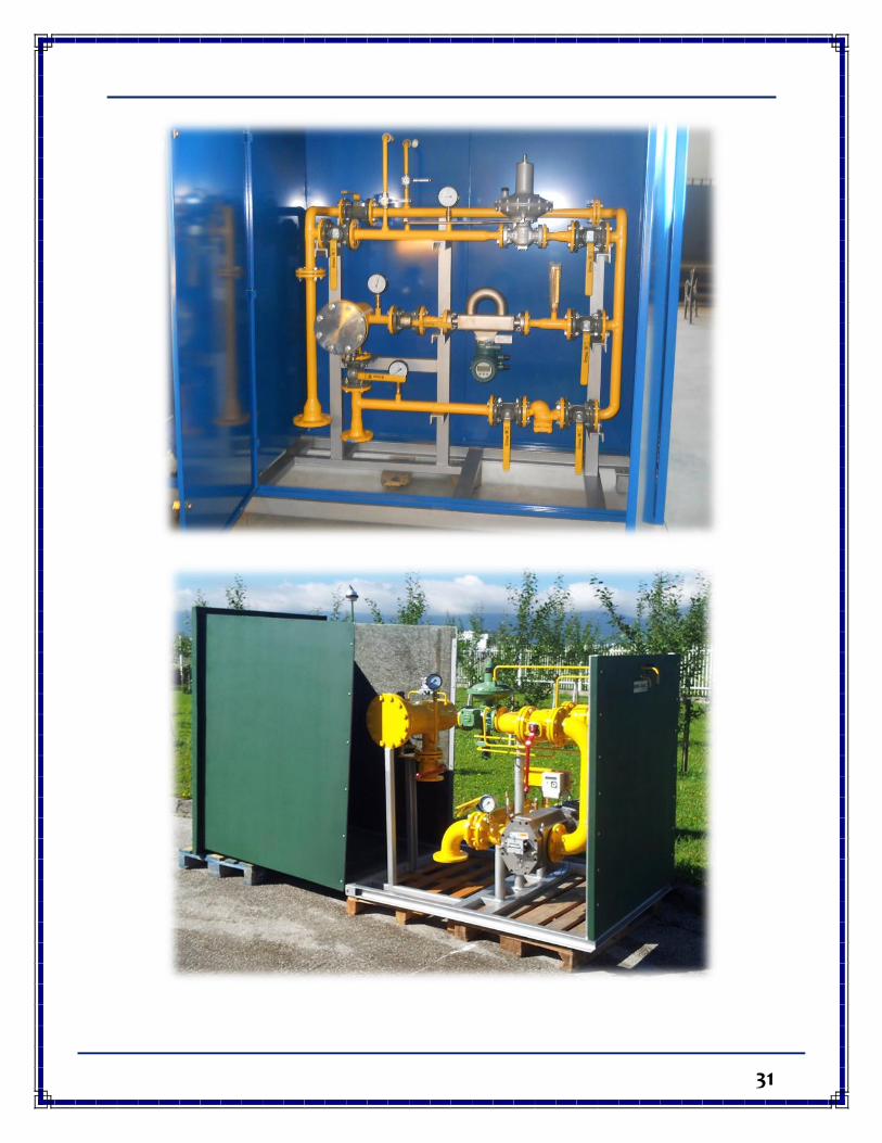
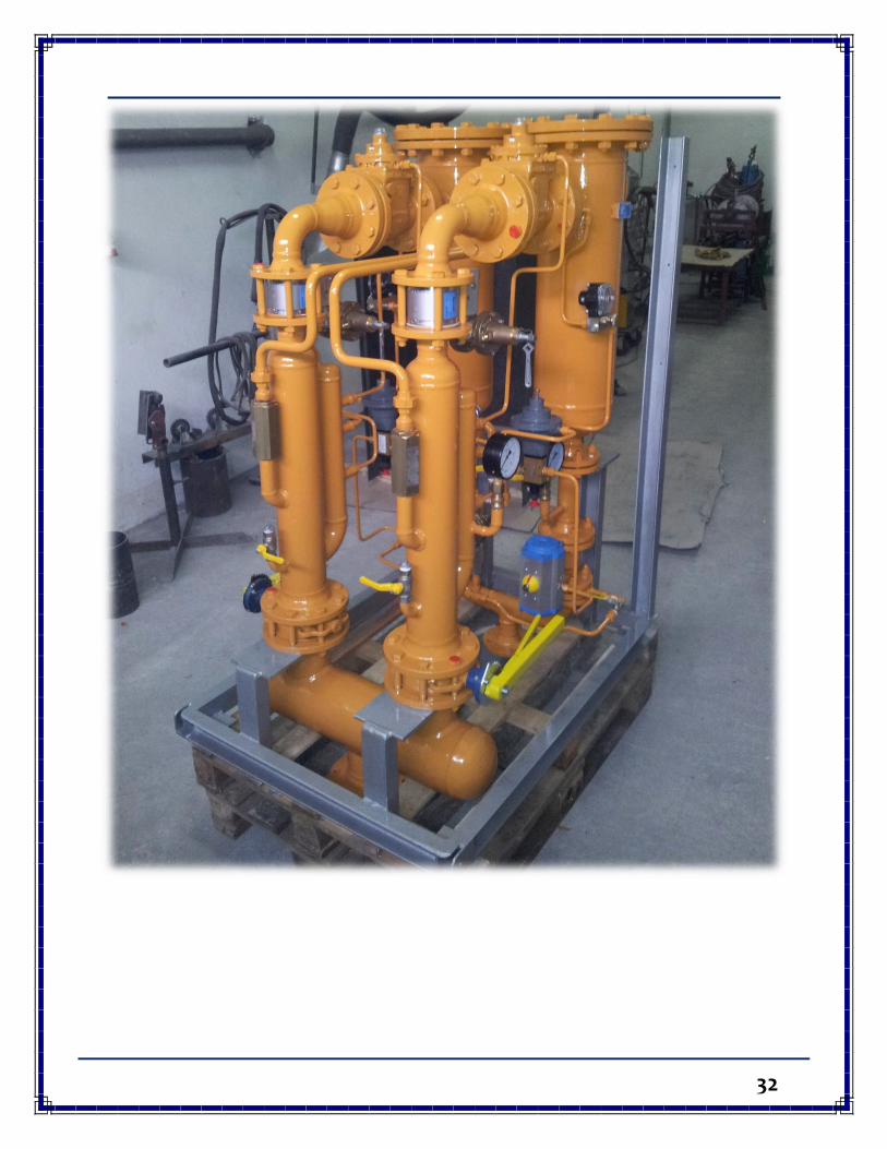
DIFFERENT TYPES OF GAS STATIONS
31
32
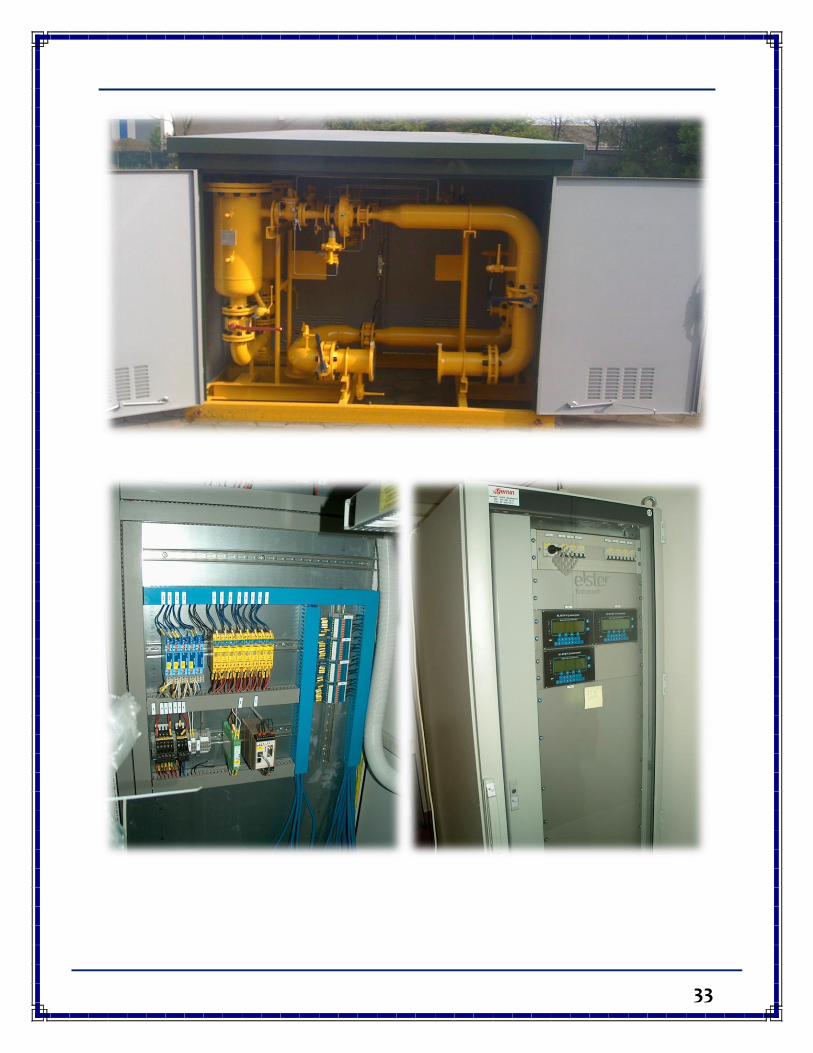
33
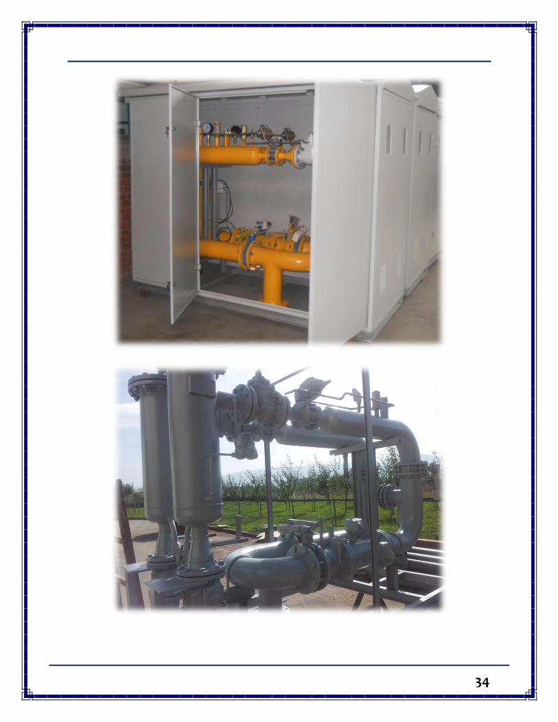
34
35
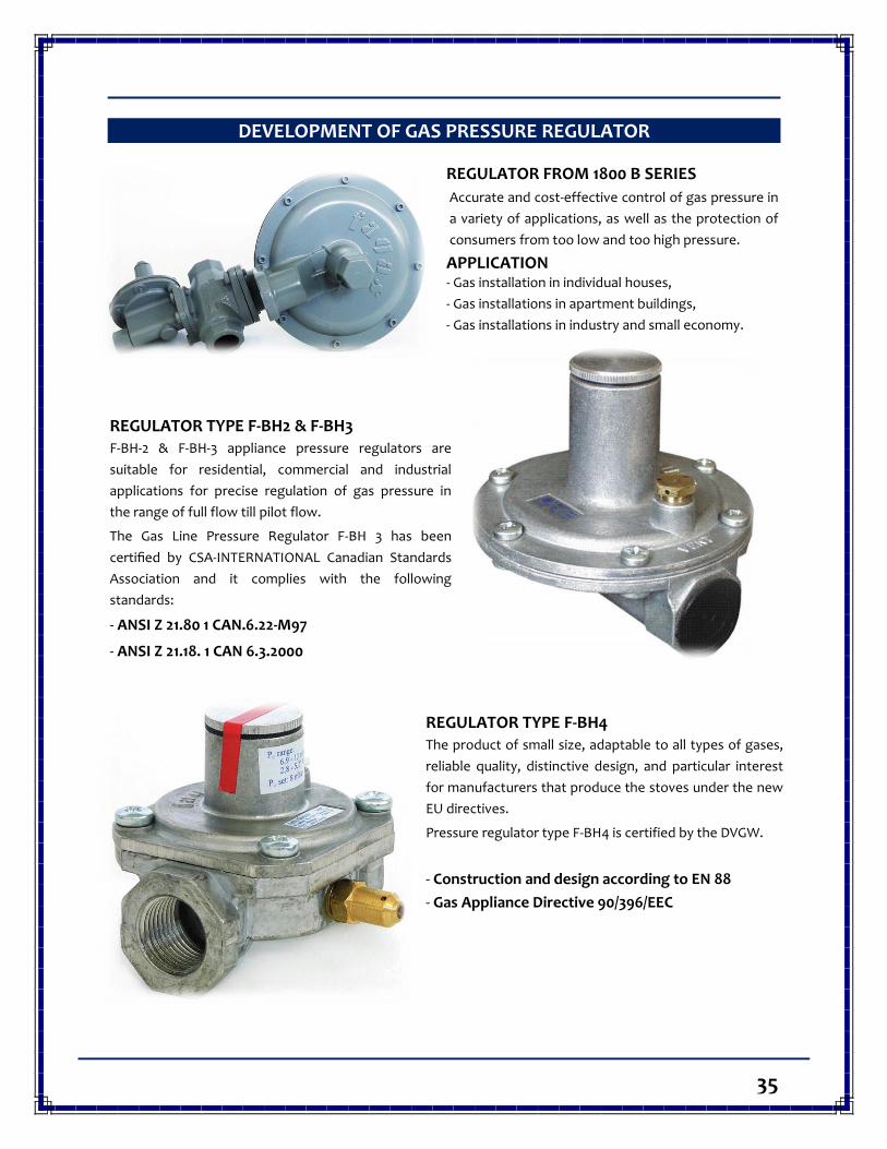
DEVELOPMENT OF GAS PRESSURE REGULATOR
REGULATOR FROM 1800 B SERIES
Accurate and cost-effective control of gas pressure in
a variety of applications, as well as the protection of
consumers from too low and too high pressure.
APPLICATION- Gas installation in individual houses,
- Gas installations in apartment buildings,
- Gas installations in industry and small economy.
REGULATOR TYPE F-BH2 & F-BH3 F-BH-2 & F-BH-3 appliance pressure regulators are
suitable for residential, commercial and industrial
applications for precise regulation of gas pressure in
the range of full flow till pilot flow.
The Gas Line Pressure Regulator F-BH 3 has been
certified by CSA-INTERNATIONAL Canadian Standards
Association and it complies with the following
standards:
- ANSI Z 21.80 1 CAN.6.22-M97
- ANSI Z 21.18. 1 CAN 6.3.2000
REGULATOR TYPE F-BH4 The product of small size, adaptable to all types of gases,
reliable quality, distinctive design, and particular interest
for manufacturers that produce the stoves under the new
EU directives.
Pressure regulator type F-BH4 is certified by the DVGW.
- Construction and design according to EN 88
- Gas Appliance Directive 90/396/EEC
37
DEVELOPMENT OF GAS FILTERS
ABOUT PRODUCT
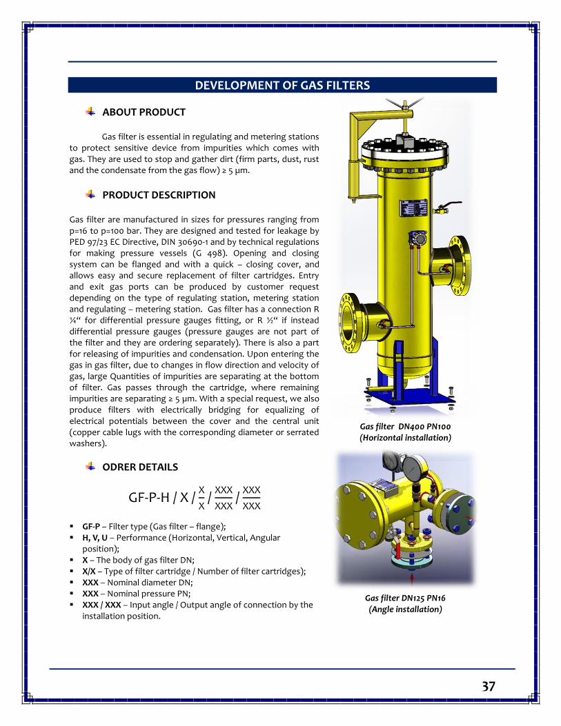
Gas filter is essential in regulating and metering stations to protect sensitive device from impurities which comes with gas. They are used to stop and gather dirt (firm parts, dust, rust and the condensate from the gas flow) ≥ 5 µm.
PRODUCT DESCRIPTION Gas filter are manufactured in sizes for pressures ranging from p=16 to p=100 bar. They are designed and tested for leakage by PED 97/23 EC Directive, DIN 30690-1 and by technical regulations for making pressure vessels (G 498). Opening and closing system can be flanged and with a quick – closing cover, and allows easy and secure replacement of filter cartridges. Entry and exit gas ports can be produced by customer request depending on the type of regulating station, metering station and regulating – metering station. Gas filter has a connection R ¼“ for differential pressure gauges fitting, or R ½“ if instead differential pressure gauges (pressure gauges are not part of the filter and they are ordering separately). There is also a part for releasing of impurities and condensation. Upon entering the gas in gas filter, due to changes in flow direction and velocity of gas, large Quantities of impurities are separating at the bottom of filter. Gas passes through the cartridge, where remaining impurities are separating ≥ 5 µm. With a special request, we also produce filters with electrically bridging for equalizing of electrical potentials between the cover and the central unit (copper cable lugs with the corresponding diameter or serrated washers).
ODRER DETAILS
GF-P-H / X / X
X /
XXX
XXX /
XXX
XXX
GF-P – Filter type (Gas filter – flange); H, V, U – Performance (Horizontal, Vertical, Angular
position); X – The body of gas filter DN; X/X – Type of filter cartridge / Number of filter cartridges); XXX – Nominal diameter DN; XXX – Nominal pressure PN; XXX / XXX – Input angle / Output angle of connection by the
installation position.
Gas filter DN400 PN100 (Horizontal installation)
Gas filter DN125 PN16 (Angle installation)
38
DEVELOPMENT OF HEAT EXCHANGERS
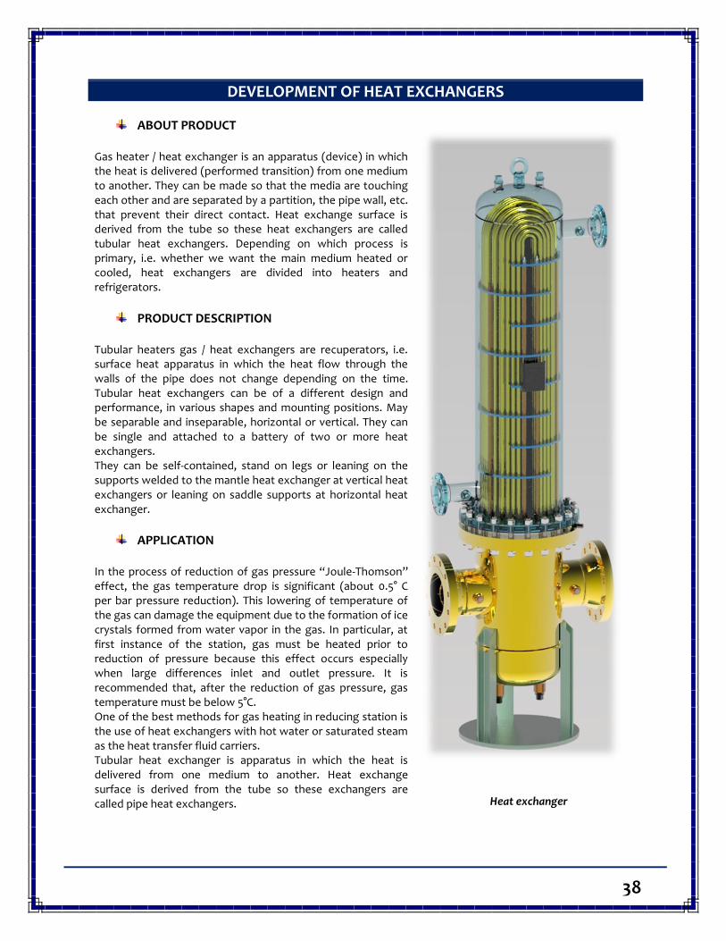
ABOUT PRODUCT Gas heater / heat exchanger is an apparatus (device) in which the heat is delivered (performed transition) from one medium to another. They can be made so that the media are touching each other and are separated by a partition, the pipe wall, etc. that prevent their direct contact. Heat exchange surface is derived from the tube so these heat exchangers are called tubular heat exchangers. Depending on which process is primary, i.e. whether we want the main medium heated or cooled, heat exchangers are divided into heaters and refrigerators.
PRODUCT DESCRIPTION Tubular heaters gas / heat exchangers are recuperators, i.e. surface heat apparatus in which the heat flow through the walls of the pipe does not change depending on the time. Tubular heat exchangers can be of a different design and performance, in various shapes and mounting positions. May be separable and inseparable, horizontal or vertical. They can be single and attached to a battery of two or more heat exchangers. They can be self-contained, stand on legs or leaning on the supports welded to the mantle heat exchanger at vertical heat exchangers or leaning on saddle supports at horizontal heat exchanger.
APPLICATION
In the process of reduction of gas pressure “Joule-Thomson” effect, the gas temperature drop is significant (about 0.5° C per bar pressure reduction). This lowering of temperature of the gas can damage the equipment due to the formation of ice crystals formed from water vapor in the gas. In particular, at first instance of the station, gas must be heated prior to reduction of pressure because this effect occurs especially when large differences inlet and outlet pressure. It is recommended that, after the reduction of gas pressure, gas temperature must be below 5°C. One of the best methods for gas heating in reducing station is the use of heat exchangers with hot water or saturated steam as the heat transfer fluid carriers. Tubular heat exchanger is apparatus in which the heat is delivered from one medium to another. Heat exchange surface is derived from the tube so these exchangers are called pipe heat exchangers.
Heat exchanger

39