Embed Size (px)
Citation preview

REFERENCENETWORK
ARCHITECTURE
CISCO VALIDATED DESIGN
REFERENCENETWORK
ARCHITECTURE
WAN Design Summary
October 2015
Cisco Validated Design
ContentsWAN Strategy ............................................................................................................................... 1
IWAN Introduction ......................................................................................................................... 5
Business Use Cases for IWAN ...................................................................................................................................... 5
IWAN Architecture ......................................................................................................................... 7
Transport-Independent Design...................................................................................................................................... 8
Intelligent Path Control .................................................................................................................................................. 9
IWAN-Aggregation Design .......................................................................................................................................... 11
IWAN Remote-Site Design .......................................................................................................................................... 17
IP Multicast .................................................................................................................................................................. 23
Quality of Service ........................................................................................................................................................ 23
IWAN Best Practices .................................................................................................................... 25
IP Routing (EIGRP or BGP) .......................................................................................................................................... 25
Quality of Service ....................................................................................................................................................... 26
Path Optimization (Performance Routing) .................................................................................................................... 26
Encryption ................................................................................................................................................................... 26
DMVPN Hub Routers ................................................................................................................................................... 29
DMVPN Spoke Router Selection.................................................................................................................................. 29
VRFs and Front Door VRF ............................................................................................................................................ 30
Summary for IWAN ...................................................................................................................... 33
Traditional WAN Introduction ...................................................................................................... 34
Business Use Cases for Traditional WAN .................................................................................................................... 34
Traditional WAN Architecture ...................................................................................................... 37
WAN-Aggregation Design .......................................................................................................................................... 37
WAN Remote-Site Design ........................................................................................................................................... 39
IP Multicast .................................................................................................................................................................. 50
Quality of Service ........................................................................................................................................................ 50
Cisco Validated Design
Traditional WAN Best Practices.................................................................................................... 52
MPLS WAN Using Layer 3 VPN ................................................................................................................................... 52
Layer 2 WAN Using VPLS or Metro Ethernet ............................................................................................................... 55
Internet with VPN WAN ............................................................................................................................................... 57
Internet 4G LTE with VPN WAN ................................................................................................................................... 59
Dynamic Multipoint VPN .............................................................................................................................................. 60
GET VPN ..................................................................................................................................................................... 64
Summary for Traditional WAN ...................................................................................................... 68
page 1Cisco Validated Design
WAN Strategy
WAN Strategy This guide provides a high level overview of several WAN technologies, followed by a discussion of the usage of each technology at the WAN-aggregation site and remote sites. This guide should be used as a roadmap on how to use the companion WAN and IWAN deployment guides. The intended audience is a technical decision maker who wants to compare Cisco’s WAN offerings and learn more about the best practices for each technology.
The days of conducting business with information stored locally on your computer are disappearing rapidly. The trend is for users to access mission-critical information by connecting to the network and downloading the information or by using a network-enabled application. Users depend upon shared access to common secured storage, web-based applications, and cloud-based services. Users may start their day at home, in the office, or from a coffee shop, expecting to log on to applications that they need in order to conduct business, update their calendar, or check email—all important tasks that support your business. Connecting to the network to do your work has become as fundamental as turning on a light switch to see your desk; it’s expected to work. Taken a step further, the network becomes a means to continue to function whether you are at your desk, roaming over wireless LAN (WLAN) within the facility, or working at a remote site, and you still have the same access to your applications and information.
Now that networks are critical to the operation and innovation of organizations, workforce productivity enhance-ments are built on the expectation of nonstop access to communications and resources. As networks become more complex in order to meet the needs of any device, any connection type, and any location, networks incur an enhanced risk of downtime caused by poor design, complex configurations, increased maintenance, or hardware and software faults. At the same time, organizations seek ways to simplify operations, reduce costs, and improve their return on investment by exploiting their investments as quickly and efficiently as possible.
The Cisco Visual Networking Index (VNI) is an ongoing effort to forecast and analyze the growth and use of IP networks worldwide. The Global Mobile Data Traffic Forecast highlights the following predictions by 2019:
• There will be 5.2 billion global mobile users, up from 4.3 billion in 2014
• There will be 11.5 billion mobile-ready devices and connections, more than 4 billion more than there were in 2014
• The average mobile connection speed will increase 2.4-fold, from 1.7 Mbps in 2014 to 4.0 Mbps by 2019
• Global mobile IP traffic will reach an annual run rate of 292 exabytes, up from 30 exabytes in 2014
With increasing mobile traffic from employee devices, an organization must plan for expanded WAN bandwidth at remote sites and larger router platforms to accommodate the higher capacity links.
The enterprise series of Cisco Validated Designs (CVDs) incorporates local area network (LAN), WLAN, wide area network (WAN), security, data center, and unified communications technologies in order to provide a complete solution for an organization’s business challenges.
page 2Cisco Validated Design
WAN Strategy
There are many ways an organization can benefit by deploying a CVD enterprise WAN architecture:
• Flexibility with multiple design models in order to address a variety of WAN technologies and resiliency op-tions
• Increased reliability with multiple remote-site designs that provide for resiliency through the addition of WAN links and WAN routers, depending on business requirements
• Scalability provided by using a consistent method for remote-site LAN connectivity based on the CVD enter-prise campus architecture
• Reduced cost of deploying a standardized design based on Cisco-tested and supported best practices
• Summarized and simplified design choices so that IT workers with a CCNA certification or equivalent experi-ence can deploy and operate the network
Using a modular approach to building your network with tested, interoperable designs allows you to reduce risks and operational issues and to increase deployment speed.
page 3Cisco Validated Design
WAN Strategy
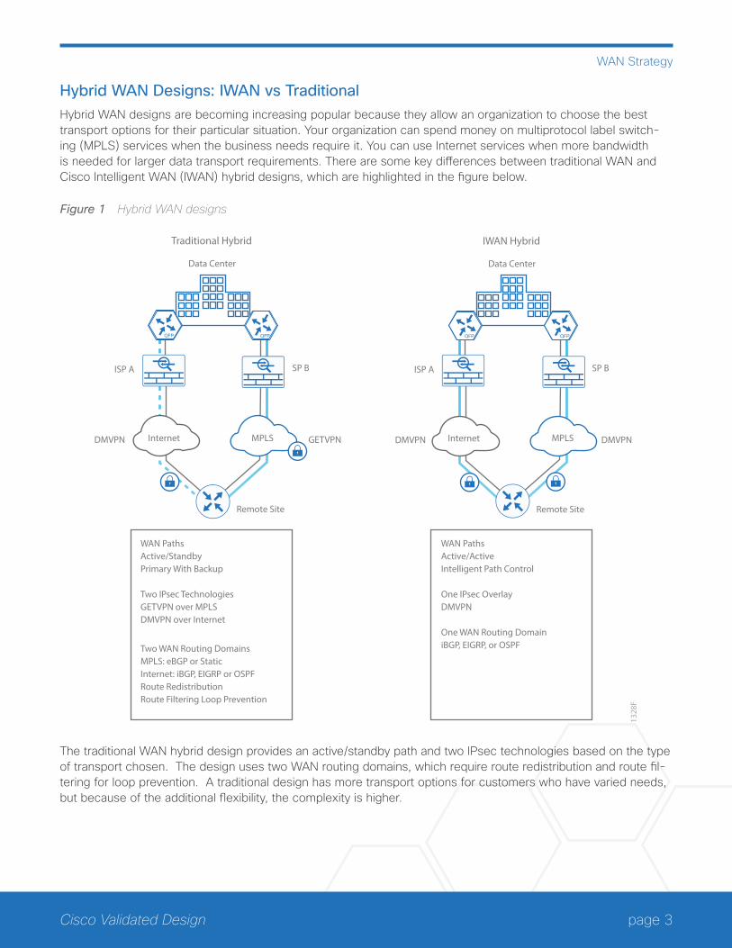
Hybrid WAN Designs: IWAN vs TraditionalHybrid WAN designs are becoming increasing popular because they allow an organization to choose the best transport options for their particular situation. Your organization can spend money on multiprotocol label switch-ing (MPLS) services when the business needs require it. You can use Internet services when more bandwidth is needed for larger data transport requirements. There are some key differences between traditional WAN and Cisco Intelligent WAN (IWAN) hybrid designs, which are highlighted in the figure below.
Figure 1 Hybrid WAN designs
1328
F
Internet MPLSDMVPN
Data Center
ISP A SP B
Remote Site
GETVPN
Traditional Hybrid
Internet MPLSDMVPN
Data Center
ISP A SP B
Remote Site
DMVPN
IWAN Hybrid
WAN PathsActive/Standby Primary With Backup
Two IPsec TechnologiesGETVPN over MPLSDMVPN over Internet
Two WAN Routing DomainsMPLS: eBGP or StaticInternet: iBGP, EIGRP or OSPFRoute RedistributionRoute Filtering Loop Prevention
WAN PathsActive/ActiveIntelligent Path Control
One IPsec OverlayDMVPN
One WAN Routing DomainiBGP, EIGRP, or OSPF
The traditional WAN hybrid design provides an active/standby path and two IPsec technologies based on the type of transport chosen. The design uses two WAN routing domains, which require route redistribution and route fil-tering for loop prevention. A traditional design has more transport options for customers who have varied needs, but because of the additional flexibility, the complexity is higher.
page 4Cisco Validated Design
WAN Strategy
The IWAN design provides an active/active path for all WAN links and uses a single IPsec technology, which is not dependent on the underlying transport. It also uses a single WAN routing domain without route redistribution or route filtering. The IWAN design is prescriptive in order to reduce the possible combinations, which lowers the cost and complexity for customers who want a simplified approach.
When planning your WAN strategy, Cisco recommends that you:
• Overprovision the WAN as much as possible
• Replace some or all of your MPLS bandwidth with Internet bandwidth
• Grow your existing WAN bandwidth with Internet bandwidth
• Keep QoS as simple as possible
• Use SDWAN management tools to automate and virtualize WAN connectivity
page 5Cisco Validated Design
IWAN Introduction
IWAN IntroductionThe Cisco IWAN solution provides design and implementation guidance for organizations looking to deploy WAN transport with a transport-independent design (TID), intelligent path control, application optimization, and secure encrypted communications between branch locations while reducing the operating cost of the WAN. IWAN takes full advantage of cost-effective transport services in order to increase bandwidth capacity without compromising performance, reliability, or security of collaboration or cloud-based applications.
BUSINESS USE CASES FOR IWANOrganizations require the WAN to provide sufficient performance and reliability for the remote-site users to be effective in supporting the business. Although most of the applications and services that the remote-site worker uses are centrally located, the WAN design must provide the workforce with a common resource-access experi-ence, regardless of location.
Carrier-based MPLS service is not always available or cost-effective for an organization to use exclusively for remote-site WAN connectivity. There are multiple WAN transport offerings that can be used simultaneously to create a robust, secure, and cost-effective WAN, including MPLS VPNs, Internet, Cellular (4G LTE), and Carrier Ethernet. Internet-based IP VPNs offer attractive bandwidth pricing and can augment premium MPLS offerings or replace MPLS in some scenarios. A flexible network architecture should include all common WAN transport offer-ings as options without significantly increasing the complexity of the overall design.
While Internet IP VPN networks present an attractive option for effective WAN connectivity, anytime an organiza-tion sends data across a public network there is risk that the data will be compromised. Loss or corruption of data can result in a regulatory violation and can present a negative public image, either of which can have significant financial impact on an organization. Secure data transport over public networks like the Internet requires adequate encryption to protect business information.
Use Case: Secure Site-to-Site WAN Communications This design helps organizations connect remote sites over private (MPLS VPN) and public (Internet) IP networks, efficiently and securely.
This design enables the following network capabilities:
• Secure, encrypted communications solutions for up to 2000 locations by using a dynamic multipoint VPN (DMVPN) IPsec tunnel overlay configuration
• A multi-homed active-active connectivity solution for resiliency and efficient use of all WAN bandwidth, using single or dual routers in remote locations
• Support for IP Multicast and replication performed on core, hub-site routers
• Compatibility with public Internet networks where NAT is implemented
• QoS for WAN traffic such as voice, video, critical data applications, bulk data applications and management traffic
page 6Cisco Validated Design
IWAN Introduction
Use Case: Transit Sites This design helps organizations scale their IWAN deployments beyond a single hub site location.
This design enables the following capabilities:
• Two or more transit sites advertise different or the same set of prefixes
• Data centers are reachable across the WAN core for each transit site
• Remote sites can access any data center across either hub location and data centers can reach any remote site across multiple transit sites
Use Case: Scale and High Availability This design helps organizations scale their IWAN deployments beyond a single hub border router per DMVPN. It also provides high availability for hub site locations.
This design enables the following capabilities:
• Horizontal scaling across multiple border routers on a single DMVPN to utilize all WAN and router capacity
• Convergence across hub routers only when all channels in a hub location fail or reach their maximum band-width limits
• If the current channel to a remote site fails, convergence to an alternate channel on the same network
• Redundant hub master controller using Anycast IP
page 7Cisco Validated Design
IWAN Architecture
IWAN ArchitectureWith the advent of globalization, WANs have become a major artery for communication between remote offices and customers in any corner of the world. Additionally, with data center consolidation, applications are moving to centralized data centers and clouds. WANs now play an even more critical role, because business survival is dependent on the availability and performance of the network.
Until now, the only way to get reliable connectivity with predictable performance was to take advantage of a private WAN using MPLS or leased line service. However, carrier-based MPLS and leased line services can be expensive and are not always cost-effective for an organization to use for WAN transport in order to support growing bandwidth requirements for remote-site connectivity. Organizations are looking for ways to lower operat-ing budget while adequately providing the network transport for a remote site.
As bandwidth demands have increased, the Internet has become a much more stable platform, and the price-to-performance gains are very attractive. However, businesses are primarily deploying “Internet as WAN” in their smaller sites or as a backup path because of the risks. Now this cost-effective, performance-enhancing opportu-nity can be realized at all your branch offices with Cisco IWAN.
Cisco IWAN enables organizations to deliver an uncompromised experience over any connection. With Cisco IWAN, IT organizations can provide more bandwidth to their branch office connections by using less expensive WAN transport options without affecting performance, security, or reliability. With the IWAN solution, traffic is dynamically routed based on application SLA, endpoint type, and network conditions in order to deliver the best quality experience. The realized savings from IWAN not only pays for the infrastructure upgrades, but also frees resources for business innovation.
page 8Cisco Validated Design
IWAN Architecture
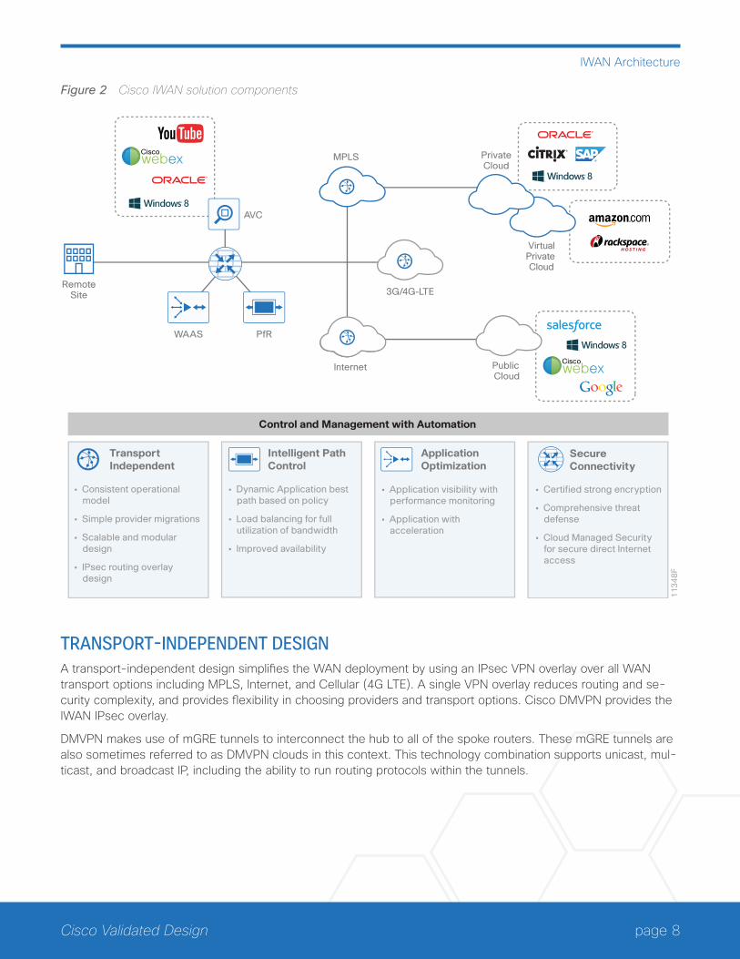
Figure 2 Cisco IWAN solution components
11
34
8F
InternetCiscowebex
MPLS
RemoteSite
AVC
WAAS PfR
3G/4G-LTE
Ciscowebex
Control and Management with Automation
PrivateCloud
VirtualPrivate Cloud
Public Cloud
Intelligent PathControl
TransportIndependent
ApplicationOptimization
SecureConnectivity
• Consistent operational model
• Simple provider migrations
• Scalable and modular design
• IPsec routing overlay design
• Dynamic Application best path based on policy
• Load balancing for full utilization of bandwidth
• Improved availability
• Application visibility with performance monitoring
• Application with acceleration
• Certified strong encryption
• Comprehensive threat defense
• Cloud Managed Security for secure direct Internet access
TRANSPORT-INDEPENDENT DESIGNA transport-independent design simplifies the WAN deployment by using an IPsec VPN overlay over all WAN transport options including MPLS, Internet, and Cellular (4G LTE). A single VPN overlay reduces routing and se-curity complexity, and provides flexibility in choosing providers and transport options. Cisco DMVPN provides the IWAN IPsec overlay.
DMVPN makes use of mGRE tunnels to interconnect the hub to all of the spoke routers. These mGRE tunnels are also sometimes referred to as DMVPN clouds in this context. This technology combination supports unicast, mul-ticast, and broadcast IP, including the ability to run routing protocols within the tunnels.
page 9Cisco Validated Design
IWAN Architecture
Internet as WAN TransportThe Internet is essentially a large-scale public IP WAN composed of multiple interconnected service providers. The Internet can provide reliable high-performance connectivity between various locations, although it lacks any explicit guarantees for these connections. Despite its “best effort” nature, the Internet is a sensible choice for augmenting premium MPLS VPN transports or as a primary WAN transport in some cases. The IWAN architec-ture leverages two or more providers for resiliency and application availability. Provider path diversity provides the foundation for PfR to route around fluctuations in the providers’ performance.
Internet connections are typically included in discussions relevant to the Internet edge, specifically for the pri-mary site. Remote-site routers also commonly have Internet connections but do not provide the same breadth of services using the Internet. For security and other reasons, Internet access at remote sites is often routed through the primary site.
Dynamic Multipoint VPNDMVPN is the recommended solution for building scalable site-to-site VPNs that support a variety of applications. DMVPN is required for IWAN deployments because it provides a tight integration with PfRv3 and simplifies route control across any transport.
DMVPN was selected for the secure overlay IWAN solution because it supports on-demand full mesh connectivity over any carrier transport with a simple hub-and-spoke configuration. DMVPN also supports spoke routers that have dynamically assigned IP addresses.
INTELLIGENT PATH CONTROLIntelligent path control improves application delivery and WAN efficiency using PfR policies to dynamically control data packet forwarding by looking at application type, performance, and path status. PfR continuously monitors the network performance for jitter, packet loss and delay, and then it makes decisions to forward critical applica-tions over the best performing path based on the application policy. PfR can evenly distribute traffic to maintain equivalent link utilization levels by using an advanced load balancing technique, even over links with differing bandwidth capacities.
page 10Cisco Validated Design
IWAN Architecture
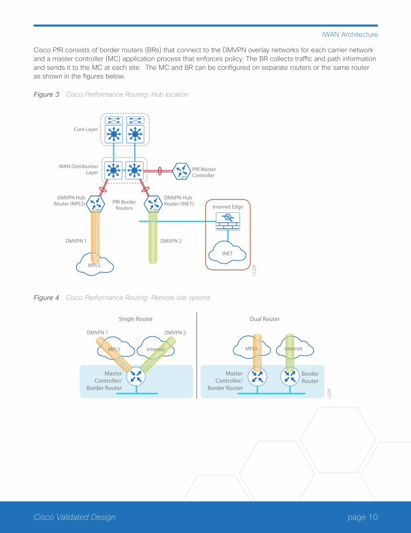
Cisco PfR consists of border routers (BRs) that connect to the DMVPN overlay networks for each carrier network and a master controller (MC) application process that enforces policy. The BR collects traffic and path information and sends it to the MC at each site. The MC and BR can be configured on separate routers or the same router as shown in the figures below.
Figure 3 Cisco Performance Routing: Hub location
WAN DistributionLayer
Core Layer
DMVPN 2
1225
F
DMVPN 1
Internet Edge
DMVPN HubRouter (MPLS)
DMVPN HubRouter (INET)
INET
PfR BorderRouters
PfR MasterController
MPLS
Figure 4 Cisco Performance Routing: Remote site options
1226
F
MPLS Internet MPLS Internet
BorderRouter
MasterController/
Border Router
DMVPN 2DMVPN 1
Single Router Dual Router
MasterController/
Border Router
page 11Cisco Validated Design
IWAN Architecture
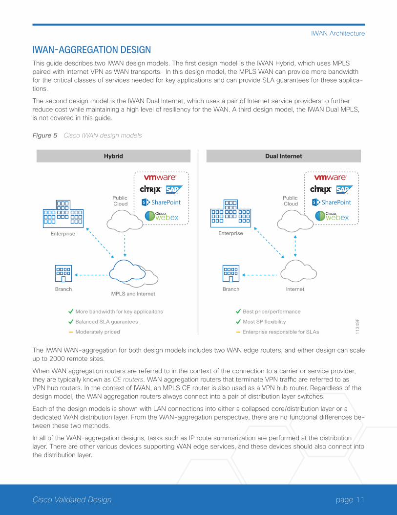
IWAN-AGGREGATION DESIGNThis guide describes two IWAN design models. The first design model is the IWAN Hybrid, which uses MPLS paired with Internet VPN as WAN transports. In this design model, the MPLS WAN can provide more bandwidth for the critical classes of services needed for key applications and can provide SLA guarantees for these applica-tions.
The second design model is the IWAN Dual Internet, which uses a pair of Internet service providers to further reduce cost while maintaining a high level of resiliency for the WAN. A third design model, the IWAN Dual MPLS, is not covered in this guide.
Figure 5 Cisco IWAN design models
11
34
9F
Ciscowebex
MPLS and Internet
Public Cloud
Hybrid
Enterprise
Branch
Ciscowebex
Internet
Public Cloud
Dual Internet
Enterprise
Branch
Best price/performance
Most SP flexibility
Enterprise responsible for SLAs
More bandwidth for key applicaitons
Balanced SLA guarantees
Moderately priced
The IWAN WAN-aggregation for both design models includes two WAN edge routers, and either design can scale up to 2000 remote sites.
When WAN aggregation routers are referred to in the context of the connection to a carrier or service provider, they are typically known as CE routers. WAN aggregation routers that terminate VPN traffic are referred to as VPN hub routers. In the context of IWAN, an MPLS CE router is also used as a VPN hub router. Regardless of the design model, the WAN aggregation routers always connect into a pair of distribution layer switches.
Each of the design models is shown with LAN connections into either a collapsed core/distribution layer or a dedicated WAN distribution layer. From the WAN-aggregation perspective, there are no functional differences be-tween these two methods.
In all of the WAN-aggregation designs, tasks such as IP route summarization are performed at the distribution layer. There are other various devices supporting WAN edge services, and these devices should also connect into the distribution layer.
page 12Cisco Validated Design
IWAN Architecture
The characteristics of each design are discussed in the following sections.
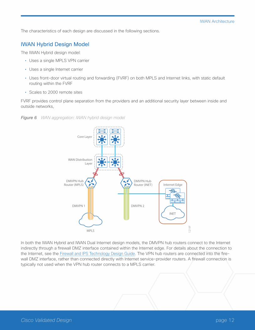
IWAN Hybrid Design ModelThe IWAN Hybrid design model:
• Uses a single MPLS VPN carrier
• Uses a single Internet carrier
• Uses front-door virtual routing and forwarding (FVRF) on both MPLS and Internet links, with static default routing within the FVRF
• Scales to 2000 remote sites
FVRF provides control plane separation from the providers and an additional security layer between inside and outside networks,
Figure 6 WAN aggregation: IWAN hybrid design model
WAN DistributionLayer
Core Layer
DMVPN 2
1219
F
MPLS
DMVPN 1
Internet EdgeDMVPN Hub
Router (MPLS)DMVPN HubRouter (INET)
INET
In both the IWAN Hybrid and IWAN Dual Internet design models, the DMVPN hub routers connect to the Internet indirectly through a firewall DMZ interface contained within the Internet edge. For details about the connection to the Internet, see the Firewall and IPS Technology Design Guide. The VPN hub routers are connected into the fire-wall DMZ interface, rather than connected directly with Internet service-provider routers. A firewall connection is typically not used when the VPN hub router connects to a MPLS carrier.
page 13Cisco Validated Design
IWAN Architecture
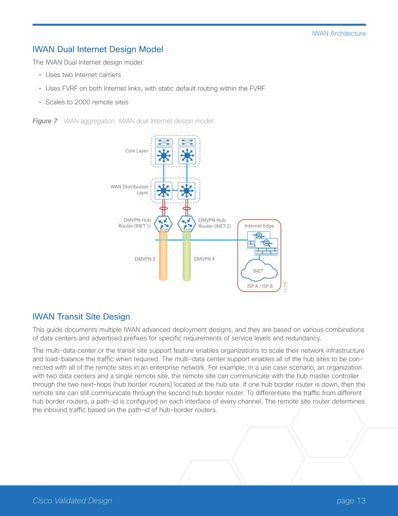
IWAN Dual Internet Design ModelThe IWAN Dual Internet design model:
• Uses two Internet carriers
• Uses FVRF on both Internet links, with static default routing within the FVRF
• Scales to 2000 remote sites
Figure 7 WAN aggregation: IWAN dual Internet design model
WAN DistributionLayer
Core Layer
DMVPN 4
1220
F
DMVPN 3
Internet EdgeDMVPN Hub
Router (INET 1)DMVPN HubRouter (INET 2)
INET
ISP A / ISP B
IWAN Transit Site DesignThis guide documents multiple IWAN advanced deployment designs, and they are based on various combinations of data centers and advertised prefixes for specific requirements of service levels and redundancy.
The multi-data center or the transit site support feature enables organizations to scale their network infrastructure and load-balance the traffic when required. The multi-data center support enables all of the hub sites to be con-nected with all of the remote sites in an enterprise network. For example, in a use case scenario, an organization with two data centers and a single remote site, the remote site can communicate with the hub master controller through the two next-hops (hub border routers) located at the hub site. If one hub border router is down, then the remote site can still communicate through the second hub border router. To differentiate the traffic from different hub border routers, a path-id is configured on each interface of every channel. The remote site router determines the inbound traffic based on the path-id of hub-border routers.
page 14Cisco Validated Design
IWAN Architecture
The transit site design models are as follows:
• Multiple data centers with multiple borders and different prefixes
• Multiple data centers with multiple borders and shared prefixes
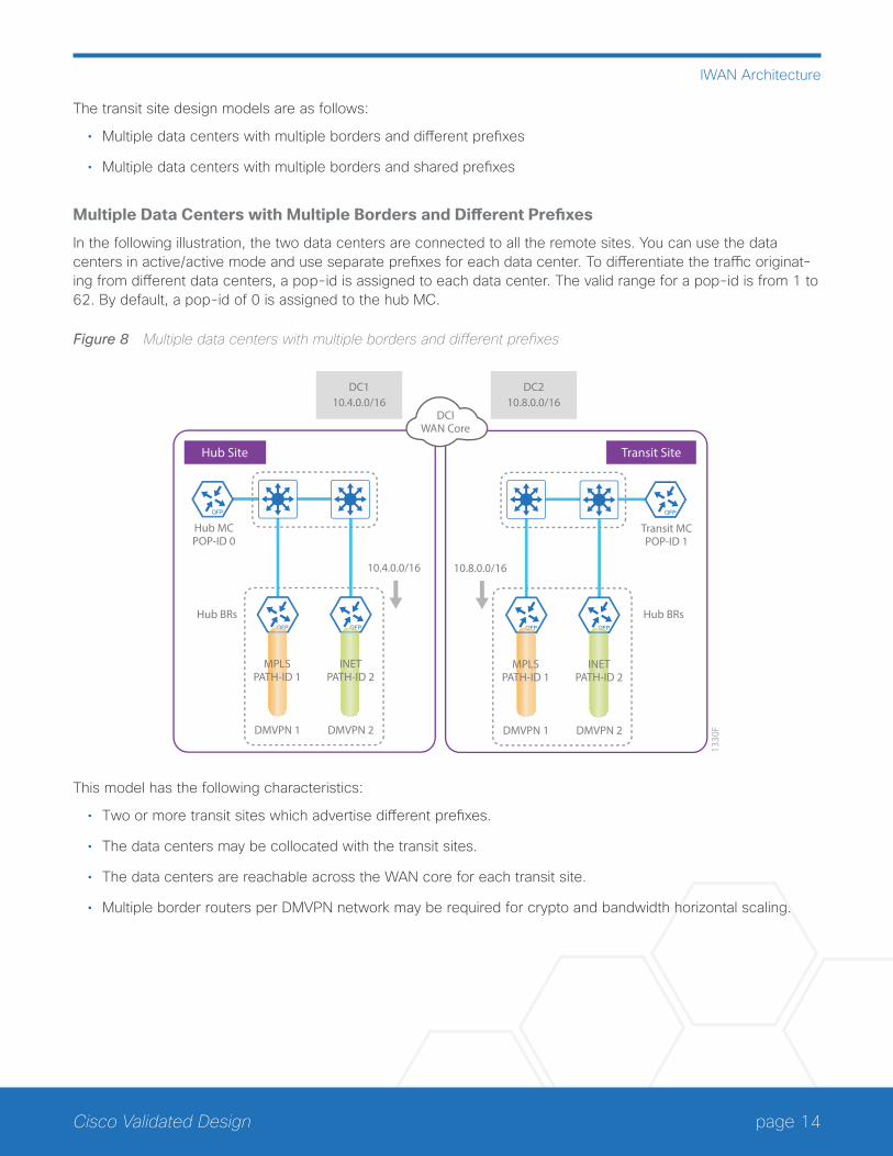
Multiple Data Centers with Multiple Borders and Different Prefixes
In the following illustration, the two data centers are connected to all the remote sites. You can use the data centers in active/active mode and use separate prefixes for each data center. To differentiate the traffic originat-ing from different data centers, a pop-id is assigned to each data center. The valid range for a pop-id is from 1 to 62. By default, a pop-id of 0 is assigned to the hub MC.
Figure 8 Multiple data centers with multiple borders and different prefixes
DMVPN 213
30FDMVPN 1
Hub MCPOP-ID 0
10.4.0.0/16
Hub Site
MPLSPATH-ID 1
INETPATH-ID 2
Hub BRs
DMVPN 2DMVPN 1
Transit MCPOP-ID 1
10.8.0.0/16
Transit Site
MPLSPATH-ID 1
INETPATH-ID 2
Hub BRs
DCIWAN Core
DC110.4.0.0/16
DC210.8.0.0/16
This model has the following characteristics:
• Two or more transit sites which advertise different prefixes.
• The data centers may be collocated with the transit sites.
• The data centers are reachable across the WAN core for each transit site.
• Multiple border routers per DMVPN network may be required for crypto and bandwidth horizontal scaling.
page 15Cisco Validated Design
IWAN Architecture
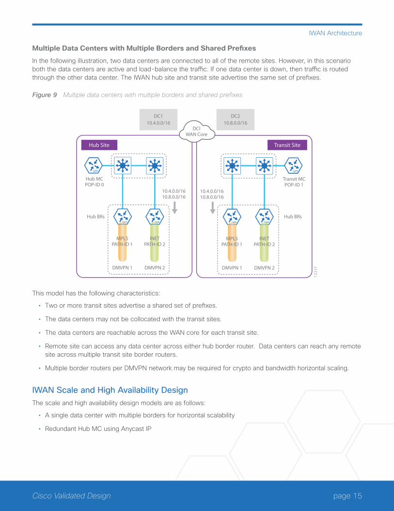
Multiple Data Centers with Multiple Borders and Shared Prefixes
In the following illustration, two data centers are connected to all of the remote sites. However, in this scenario both the data centers are active and load-balance the traffic. If one data center is down, then traffic is routed through the other data center. The IWAN hub site and transit site advertise the same set of prefixes.
Figure 9 Multiple data centers with multiple borders and shared prefixes
DMVPN 2
1331
FDMVPN 1
Hub MCPOP-ID 0
10.4.0.0/1610.8.0.0/16
Hub Site
MPLSPATH-ID 1
INETPATH-ID 2
Hub BRs
DMVPN 2DMVPN 1
Transit MCPOP-ID 1
10.4.0.0/1610.8.0.0/16
Transit Site
MPLSPATH-ID 1
INETPATH-ID 2
Hub BRs
DCIWAN Core
DC110.4.0.0/16
DC210.8.0.0/16
This model has the following characteristics:
• Two or more transit sites advertise a shared set of prefixes.
• The data centers may not be collocated with the transit sites.
• The data centers are reachable across the WAN core for each transit site.
• Remote site can access any data center across either hub border router. Data centers can reach any remote site across multiple transit site border routers.
• Multiple border routers per DMVPN network may be required for crypto and bandwidth horizontal scaling.
IWAN Scale and High Availability DesignThe scale and high availability design models are as follows:
• A single data center with multiple borders for horizontal scalability
• Redundant Hub MC using Anycast IP
page 16Cisco Validated Design
IWAN Architecture
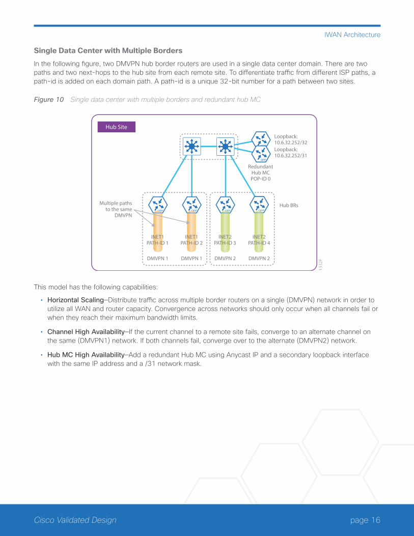
Single Data Center with Multiple Borders
In the following figure, two DMVPN hub border routers are used in a single data center domain. There are two paths and two next-hops to the hub site from each remote site. To differentiate traffic from different ISP paths, a path-id is added on each domain path. A path-id is a unique 32-bit number for a path between two sites.
Figure 10 Single data center with multiple borders and redundant hub MC
DMVPN 1
1332
FDMVPN 1
RedundantHub MCPOP-ID 0
Loopback:10.6.32.252/32
Hub Site
INET1PATH-ID 1
Multiple pathsto the same
DMVPN
Loopback:10.6.32.252/31
DMVPN 2DMVPN 2
INET2PATH-ID 4
Hub BRs
INET1PATH-ID 2
INET2PATH-ID 3
This model has the following capabilities:
• Horizontal Scaling—Distribute traffic across multiple border routers on a single (DMVPN) network in order to utilize all WAN and router capacity. Convergence across networks should only occur when all channels fail or when they reach their maximum bandwidth limits.
• Channel High Availability—If the current channel to a remote site fails, converge to an alternate channel on the same (DMVPN1) network. If both channels fail, converge over to the alternate (DMVPN2) network.
• Hub MC High Availability—Add a redundant Hub MC using Anycast IP and a secondary loopback interface with the same IP address and a /31 network mask.
page 17Cisco Validated Design
IWAN Architecture
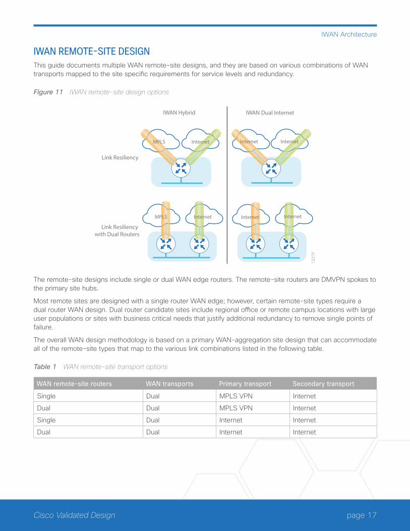
IWAN REMOTE-SITE DESIGNThis guide documents multiple WAN remote-site designs, and they are based on various combinations of WAN transports mapped to the site specific requirements for service levels and redundancy.
Figure 11 IWAN remote-site design options
Link Resiliency with Dual Routers
Link Resiliency
1221
F
IWAN Hybrid IWAN Dual Internet
MPLS Internet Internet Internet
MPLS InternetInternet Internet
The remote-site designs include single or dual WAN edge routers. The remote-site routers are DMVPN spokes to the primary site hubs.
Most remote sites are designed with a single router WAN edge; however, certain remote-site types require a dual router WAN design. Dual router candidate sites include regional office or remote campus locations with large user populations or sites with business critical needs that justify additional redundancy to remove single points of failure.
The overall WAN design methodology is based on a primary WAN-aggregation site design that can accommodate all of the remote-site types that map to the various link combinations listed in the following table.
Table 1 WAN remote-site transport options
WAN remote-site routers WAN transports Primary transport Secondary transport
Single Dual MPLS VPN Internet
Dual Dual MPLS VPN Internet
Single Dual Internet Internet
Dual Dual Internet Internet
page 18Cisco Validated Design
IWAN Architecture
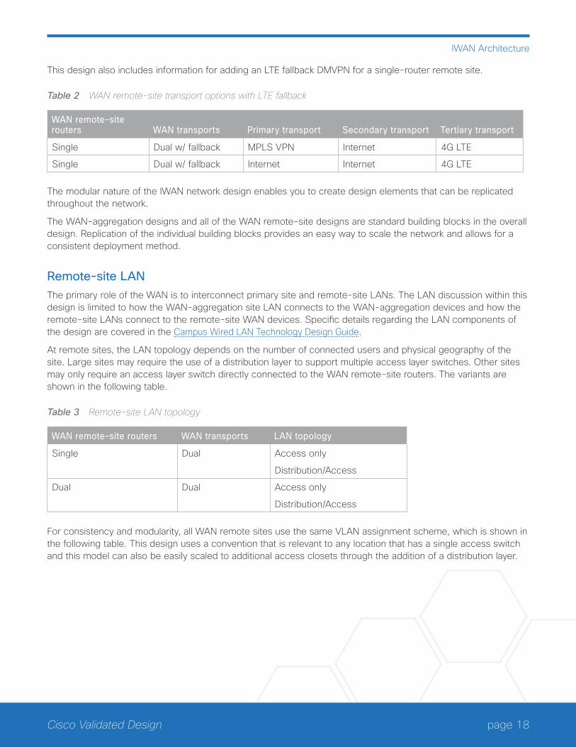
This design also includes information for adding an LTE fallback DMVPN for a single-router remote site.
Table 2 WAN remote-site transport options with LTE fallback
WAN remote-site routers WAN transports Primary transport Secondary transport Tertiary transport
Single Dual w/ fallback MPLS VPN Internet 4G LTE
Single Dual w/ fallback Internet Internet 4G LTE
The modular nature of the IWAN network design enables you to create design elements that can be replicated throughout the network.
The WAN-aggregation designs and all of the WAN remote-site designs are standard building blocks in the overall design. Replication of the individual building blocks provides an easy way to scale the network and allows for a consistent deployment method.
Remote-site LANThe primary role of the WAN is to interconnect primary site and remote-site LANs. The LAN discussion within this design is limited to how the WAN-aggregation site LAN connects to the WAN-aggregation devices and how the remote-site LANs connect to the remote-site WAN devices. Specific details regarding the LAN components of the design are covered in the Campus Wired LAN Technology Design Guide.
At remote sites, the LAN topology depends on the number of connected users and physical geography of the site. Large sites may require the use of a distribution layer to support multiple access layer switches. Other sites may only require an access layer switch directly connected to the WAN remote-site routers. The variants are shown in the following table.
Table 3 Remote-site LAN topology
WAN remote-site routers WAN transports LAN topology
Single Dual Access only
Distribution/Access
Dual Dual Access only
Distribution/Access
For consistency and modularity, all WAN remote sites use the same VLAN assignment scheme, which is shown in the following table. This design uses a convention that is relevant to any location that has a single access switch and this model can also be easily scaled to additional access closets through the addition of a distribution layer.
page 19Cisco Validated Design
IWAN Architecture
Table 4 Remote-site VLAN assignment
VLAN Usage Layer 2 access Layer 3 distribution/access
VLAN 64 Data 1 Yes —
VLAN 69 Voice 1 Yes —
VLAN 99 Transit Yes
(dual router only)
Yes
(dual router only)
VLAN 50 Router Link (1) — Yes
VLAN 54 Router Link (2) — Yes
(dual router only)
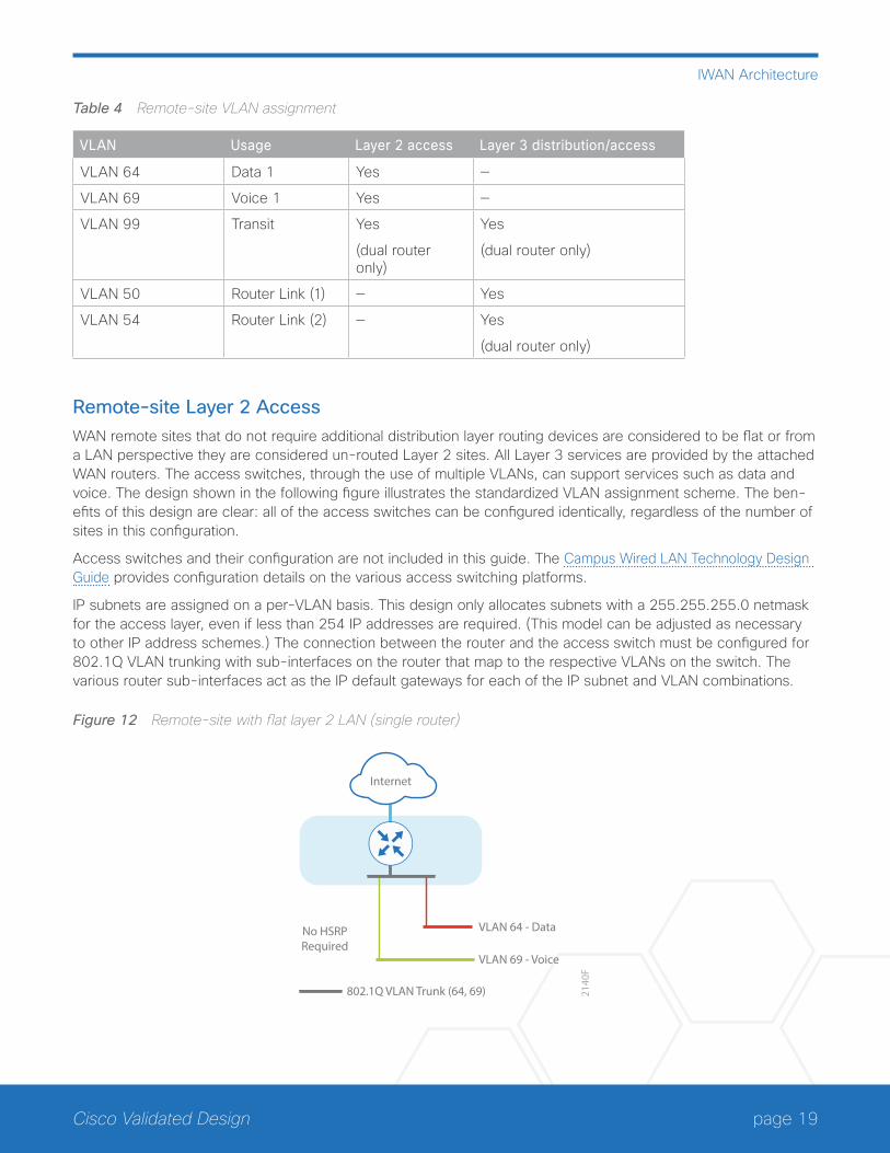
Remote-site Layer 2 AccessWAN remote sites that do not require additional distribution layer routing devices are considered to be flat or from a LAN perspective they are considered un-routed Layer 2 sites. All Layer 3 services are provided by the attached WAN routers. The access switches, through the use of multiple VLANs, can support services such as data and voice. The design shown in the following figure illustrates the standardized VLAN assignment scheme. The ben-efits of this design are clear: all of the access switches can be configured identically, regardless of the number of sites in this configuration.
Access switches and their configuration are not included in this guide. The Campus Wired LAN Technology Design Guide provides configuration details on the various access switching platforms.
IP subnets are assigned on a per-VLAN basis. This design only allocates subnets with a 255.255.255.0 netmask for the access layer, even if less than 254 IP addresses are required. (This model can be adjusted as necessary to other IP address schemes.) The connection between the router and the access switch must be configured for 802.1Q VLAN trunking with sub-interfaces on the router that map to the respective VLANs on the switch. The various router sub-interfaces act as the IP default gateways for each of the IP subnet and VLAN combinations.
Figure 12 Remote-site with flat layer 2 LAN (single router)
Internet
No HSRPRequired
VLAN 64 - Data
802.1Q VLAN Trunk (64, 69)
VLAN 69 - Voice
2140
F
page 20Cisco Validated Design
IWAN Architecture
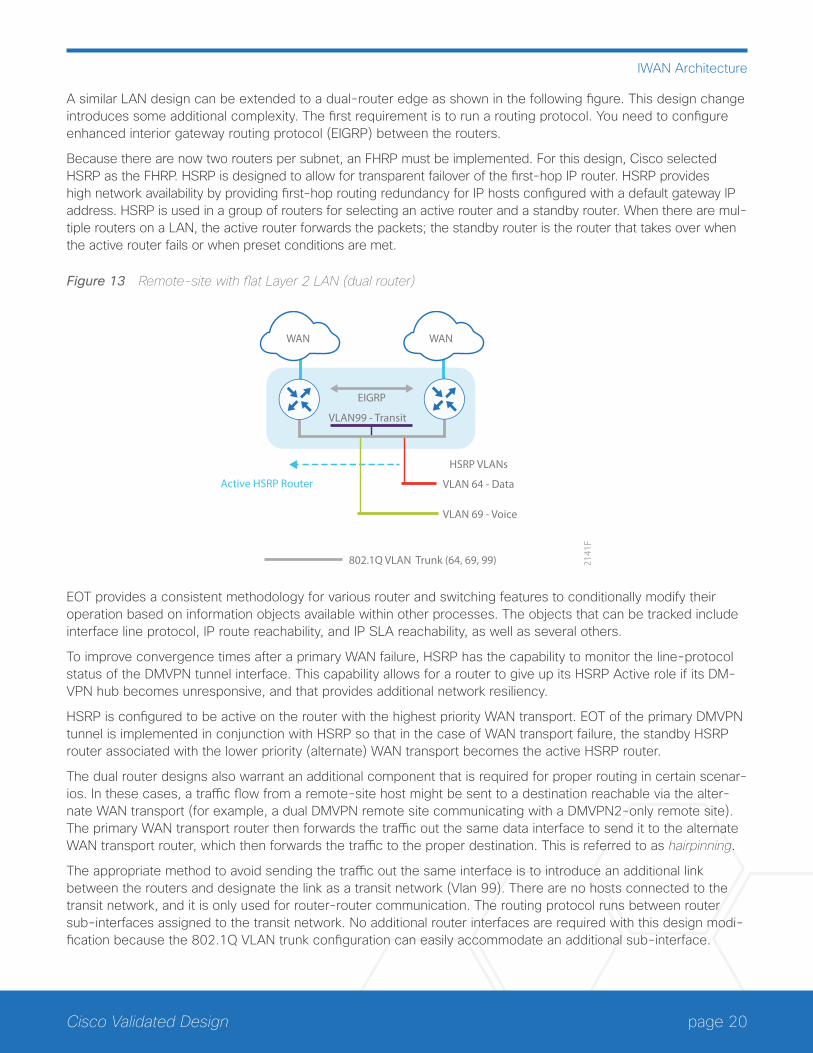
A similar LAN design can be extended to a dual-router edge as shown in the following figure. This design change introduces some additional complexity. The first requirement is to run a routing protocol. You need to configure enhanced interior gateway routing protocol (EIGRP) between the routers.
Because there are now two routers per subnet, an FHRP must be implemented. For this design, Cisco selected HSRP as the FHRP. HSRP is designed to allow for transparent failover of the first-hop IP router. HSRP provides high network availability by providing first-hop routing redundancy for IP hosts configured with a default gateway IP address. HSRP is used in a group of routers for selecting an active router and a standby router. When there are mul-tiple routers on a LAN, the active router forwards the packets; the standby router is the router that takes over when the active router fails or when preset conditions are met.
Figure 13 Remote-site with flat Layer 2 LAN (dual router)
WAN WAN
Active HSRP Router VLAN 64 - Data
VLAN99 - Transit
802.1Q VLAN Trunk (64, 69, 99)
VLAN 69 - Voice
2141
F
HSRP VLANs
EIGRP
EOT provides a consistent methodology for various router and switching features to conditionally modify their operation based on information objects available within other processes. The objects that can be tracked include interface line protocol, IP route reachability, and IP SLA reachability, as well as several others.
To improve convergence times after a primary WAN failure, HSRP has the capability to monitor the line-protocol status of the DMVPN tunnel interface. This capability allows for a router to give up its HSRP Active role if its DM-VPN hub becomes unresponsive, and that provides additional network resiliency.
HSRP is configured to be active on the router with the highest priority WAN transport. EOT of the primary DMVPN tunnel is implemented in conjunction with HSRP so that in the case of WAN transport failure, the standby HSRP router associated with the lower priority (alternate) WAN transport becomes the active HSRP router.
The dual router designs also warrant an additional component that is required for proper routing in certain scenar-ios. In these cases, a traffic flow from a remote-site host might be sent to a destination reachable via the alter-nate WAN transport (for example, a dual DMVPN remote site communicating with a DMVPN2-only remote site). The primary WAN transport router then forwards the traffic out the same data interface to send it to the alternate WAN transport router, which then forwards the traffic to the proper destination. This is referred to as hairpinning.
The appropriate method to avoid sending the traffic out the same interface is to introduce an additional link between the routers and designate the link as a transit network (Vlan 99). There are no hosts connected to the transit network, and it is only used for router-router communication. The routing protocol runs between router sub-interfaces assigned to the transit network. No additional router interfaces are required with this design modi-fication because the 802.1Q VLAN trunk configuration can easily accommodate an additional sub-interface.
page 21Cisco Validated Design
IWAN Architecture
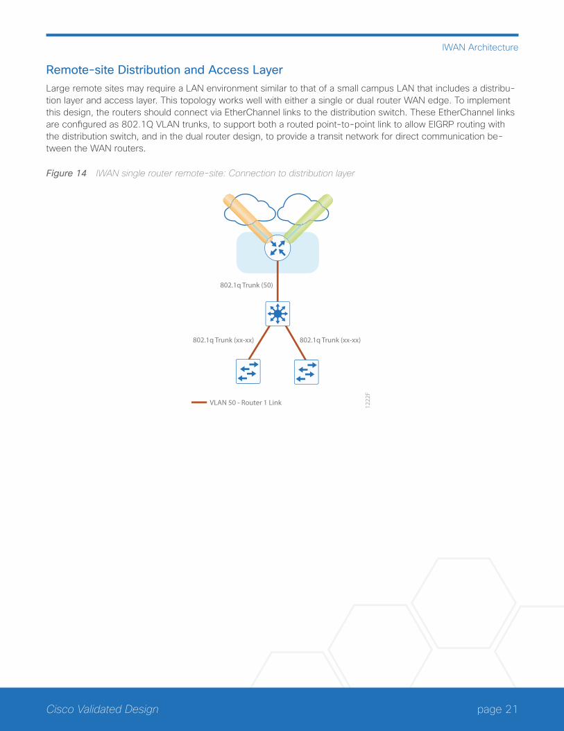
Remote-site Distribution and Access LayerLarge remote sites may require a LAN environment similar to that of a small campus LAN that includes a distribu-tion layer and access layer. This topology works well with either a single or dual router WAN edge. To implement this design, the routers should connect via EtherChannel links to the distribution switch. These EtherChannel links are configured as 802.1Q VLAN trunks, to support both a routed point-to-point link to allow EIGRP routing with the distribution switch, and in the dual router design, to provide a transit network for direct communication be-tween the WAN routers.
Figure 14 IWAN single router remote-site: Connection to distribution layer
1222
F
VLAN 50 - Router 1 Link
802.1q Trunk (xx-xx)
802.1q Trunk (50)
802.1q Trunk (xx-xx)
page 22Cisco Validated Design
IWAN Architecture
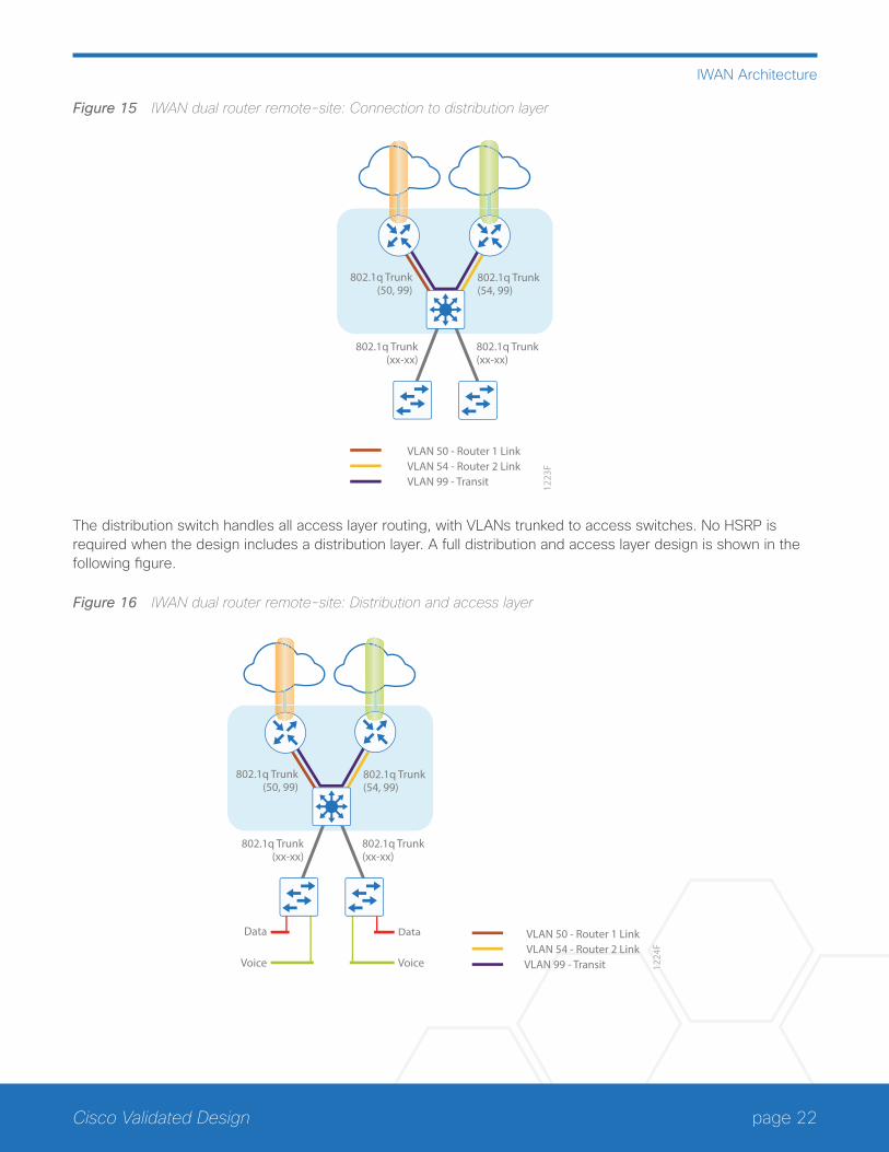
Figure 15 IWAN dual router remote-site: Connection to distribution layer
VLAN 50 - Router 1 Link
802.1q Trunk(xx-xx)
802.1q Trunk(xx-xx)
802.1q Trunk(50, 99)
802.1q Trunk(54, 99)
VLAN 54 - Router 2 LinkVLAN 99 - Transit 12
23F
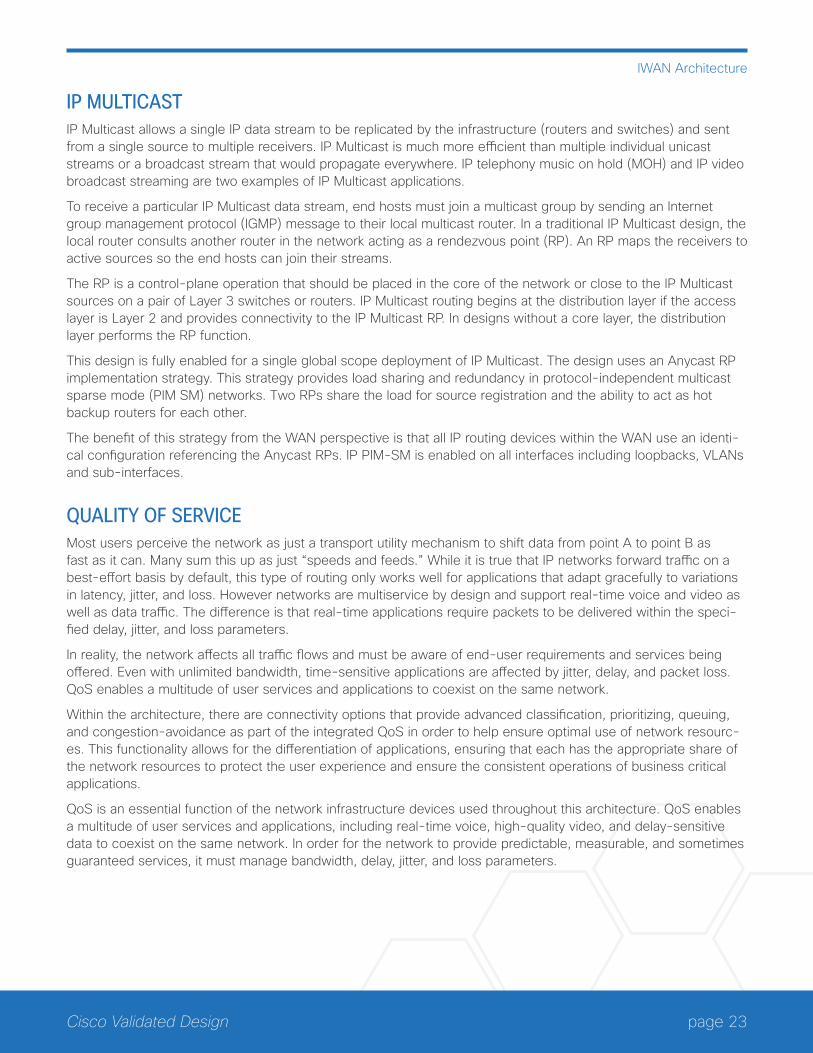
The distribution switch handles all access layer routing, with VLANs trunked to access switches. No HSRP is required when the design includes a distribution layer. A full distribution and access layer design is shown in the following figure.
Figure 16 IWAN dual router remote-site: Distribution and access layer
VLAN 50 - Router 1 Link
802.1q Trunk(xx-xx)
802.1q Trunk(xx-xx)
802.1q Trunk(50, 99)
802.1q Trunk(54, 99)
VLAN 54 - Router 2 LinkVLAN 99 - Transit 12
24F
Data
Voice
Data
Voice
page 23Cisco Validated Design
IWAN Architecture
IP MULTICASTIP Multicast allows a single IP data stream to be replicated by the infrastructure (routers and switches) and sent from a single source to multiple receivers. IP Multicast is much more efficient than multiple individual unicast streams or a broadcast stream that would propagate everywhere. IP telephony music on hold (MOH) and IP video broadcast streaming are two examples of IP Multicast applications.
To receive a particular IP Multicast data stream, end hosts must join a multicast group by sending an Internet group management protocol (IGMP) message to their local multicast router. In a traditional IP Multicast design, the local router consults another router in the network acting as a rendezvous point (RP). An RP maps the receivers to active sources so the end hosts can join their streams.
The RP is a control-plane operation that should be placed in the core of the network or close to the IP Multicast sources on a pair of Layer 3 switches or routers. IP Multicast routing begins at the distribution layer if the access layer is Layer 2 and provides connectivity to the IP Multicast RP. In designs without a core layer, the distribution layer performs the RP function.
This design is fully enabled for a single global scope deployment of IP Multicast. The design uses an Anycast RP implementation strategy. This strategy provides load sharing and redundancy in protocol-independent multicast sparse mode (PIM SM) networks. Two RPs share the load for source registration and the ability to act as hot backup routers for each other.
The benefit of this strategy from the WAN perspective is that all IP routing devices within the WAN use an identi-cal configuration referencing the Anycast RPs. IP PIM-SM is enabled on all interfaces including loopbacks, VLANs and sub-interfaces.
QUALITY OF SERVICEMost users perceive the network as just a transport utility mechanism to shift data from point A to point B as fast as it can. Many sum this up as just “speeds and feeds.” While it is true that IP networks forward traffic on a best-effort basis by default, this type of routing only works well for applications that adapt gracefully to variations in latency, jitter, and loss. However networks are multiservice by design and support real-time voice and video as well as data traffic. The difference is that real-time applications require packets to be delivered within the speci-fied delay, jitter, and loss parameters.
In reality, the network affects all traffic flows and must be aware of end-user requirements and services being offered. Even with unlimited bandwidth, time-sensitive applications are affected by jitter, delay, and packet loss. QoS enables a multitude of user services and applications to coexist on the same network.
Within the architecture, there are connectivity options that provide advanced classification, prioritizing, queuing, and congestion-avoidance as part of the integrated QoS in order to help ensure optimal use of network resourc-es. This functionality allows for the differentiation of applications, ensuring that each has the appropriate share of the network resources to protect the user experience and ensure the consistent operations of business critical applications.
QoS is an essential function of the network infrastructure devices used throughout this architecture. QoS enables a multitude of user services and applications, including real-time voice, high-quality video, and delay-sensitive data to coexist on the same network. In order for the network to provide predictable, measurable, and sometimes guaranteed services, it must manage bandwidth, delay, jitter, and loss parameters.
page 24Cisco Validated Design
IWAN Architecture
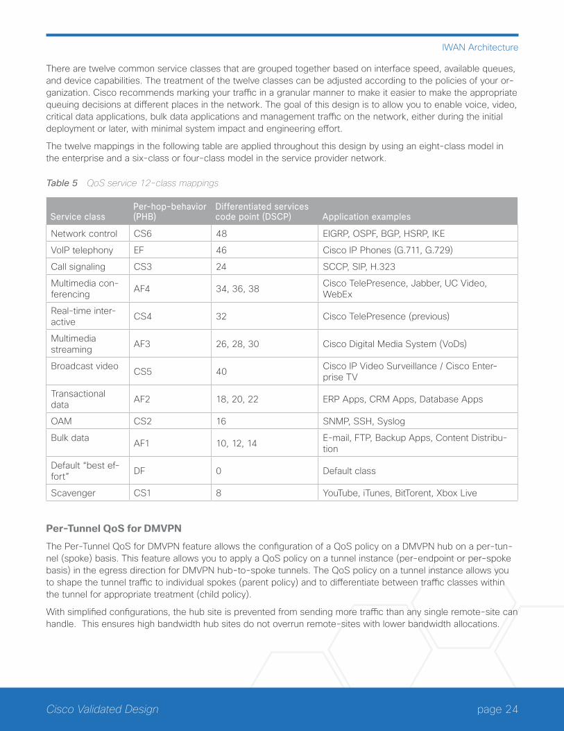
There are twelve common service classes that are grouped together based on interface speed, available queues, and device capabilities. The treatment of the twelve classes can be adjusted according to the policies of your or-ganization. Cisco recommends marking your traffic in a granular manner to make it easier to make the appropriate queuing decisions at different places in the network. The goal of this design is to allow you to enable voice, video, critical data applications, bulk data applications and management traffic on the network, either during the initial deployment or later, with minimal system impact and engineering effort.
The twelve mappings in the following table are applied throughout this design by using an eight-class model in the enterprise and a six-class or four-class model in the service provider network.
Table 5 QoS service 12-class mappings
Service classPer-hop-behavior (PHB)
Differentiated services code point (DSCP) Application examples
Network control CS6 48 EIGRP, OSPF, BGP, HSRP, IKE
VoIP telephony EF 46 Cisco IP Phones (G.711, G.729)
Call signaling CS3 24 SCCP, SIP, H.323
Multimedia con-ferencing AF4 34, 36, 38 Cisco TelePresence, Jabber, UC Video,
WebEx
Real-time inter-active CS4 32 Cisco TelePresence (previous)
Multimedia streaming AF3 26, 28, 30 Cisco Digital Media System (VoDs)
Broadcast video CS5 40 Cisco IP Video Surveillance / Cisco Enter-prise TV
Transactional data AF2 18, 20, 22 ERP Apps, CRM Apps, Database Apps
OAM CS2 16 SNMP, SSH, Syslog
Bulk data AF1 10, 12, 14 E-mail, FTP, Backup Apps, Content Distribu-tion
Default “best ef-fort” DF 0 Default class
Scavenger CS1 8 YouTube, iTunes, BitTorent, Xbox Live
Per-Tunnel QoS for DMVPN
The Per-Tunnel QoS for DMVPN feature allows the configuration of a QoS policy on a DMVPN hub on a per-tun-nel (spoke) basis. This feature allows you to apply a QoS policy on a tunnel instance (per-endpoint or per-spoke basis) in the egress direction for DMVPN hub-to-spoke tunnels. The QoS policy on a tunnel instance allows you to shape the tunnel traffic to individual spokes (parent policy) and to differentiate between traffic classes within the tunnel for appropriate treatment (child policy).
With simplified configurations, the hub site is prevented from sending more traffic than any single remote-site can handle. This ensures high bandwidth hub sites do not overrun remote-sites with lower bandwidth allocations.
page 25Cisco Validated Design
IWAN Best Practices
IWAN Best PracticesThe next several sections will cover best practices from the IWAN perspective.
IP ROUTING (EIGRP OR BGP)The design has the following IP routing goals:
• Provide optimal routing connectivity from primary WAN-aggregation sites to all remote locations
• Isolate WAN routing topology changes from other portions of the network
• Ensure active/standby symmetric routing when multiple paths exist, for ease of troubleshooting and to pre-vent oversubscription of IP telephony call admission control (CAC) limits
• Provide a solid underlying IP routed topology in order to support the Intelligent Path Control provided by Cisco Performance Routing.
• Provide site-site remote routing via the primary WAN-aggregation site (hub-and-spoke model)
• Permit optimal direct site-site remote routing (spoke-to-spoke model)
• Support IP Multicast sourced from the primary WAN-aggregation site
At the WAN remote sites, there is no local Internet access for web browsing or cloud services. This model is re-ferred to as a centralized Internet model. It is worth noting that sites with Internet/DMVPN could potentially provide local Internet capability; however, for this design, only encrypted traffic to other DMVPN sites is permitted to use the Internet link. In the centralized Internet model, a default route is advertised to the WAN remote sites in addi-tion to the internal routes from the data center and campus.
The network must tolerate single failure conditions including the failure of any single WAN transport link or any single network device at the primary WAN-aggregation site.
Cisco uses EIGRP as the primary routing protocol because it is easy to configure, does not require a large amount of planning, has flexible summarization and filtering, and can scale to large networks. As networks grow, the number of IP prefixes or routes in the routing tables grows as well. You should program IP summarization on links where logical boundaries exist, like distribution layer links to the wide area or to a core. By performing IP summa-rization, you can reduce the amount of bandwidth, processor, and memory necessary to carry large route tables, as well as reduce convergence time associated with a link failure.
page 26Cisco Validated Design
IWAN Best Practices
With the advances in EIGRP, this guide uses EIGRP named mode. The use of named mode EIGRP allows related EIGRP configurations to be centrally located in the configuration. Named mode EIGRP includes features such as wide metrics, supporting larger multi-gigabit links. For added security, EIGRP neighbor authentication has been implemented to prevent unauthorized neighbor associations.
Tech Tip
With EIGRP named mode configuration, EIGRP Wide Metric support is on by default and backward compatible with existing routes.
You can also use Internal BGP as an overlay routing protocol. For design guidance, see the IWAN Technology Design Guide.
QUALITY OF SERVICE The network must ensure that business applications perform across the WAN during times of network congestion. Traffic must be classified and queued and the WAN connection must be shaped to operate within the capabilities of the connection. When the WAN design uses a service provider offering with QoS, the WAN edge QoS classi-fication and treatment must align to the service provider in order to ensure consistent end-to-end QoS treatment of traffic.
PATH OPTIMIZATION (PERFORMANCE ROUTING)The network must protect business critical applications from fluctuating WAN performance by using the best-performing path based on the application policy. The design must also intelligently load-balance traffic in order to reduce an organization’s overall communications expenses by allowing them to use a less expensive Internet transport without negatively affecting their mission critical traffic.
Remote sites classified as single-router, dual-link must be able tolerate the loss of either WAN transport. Remote sites classified as dual-router, dual-link must be able to tolerate the loss of either an edge router or a WAN trans-port.
ENCRYPTIONThe primary goal of encryption is to provide data confidentiality, integrity, and authenticity by encrypting IP packets as the data travels across a network.
The encrypted payloads are then encapsulated with a new header (or multiple headers) and transmitted across the network. The additional headers introduce a certain amount of overhead to the overall packet length.
page 27Cisco Validated Design
IWAN Best Practices
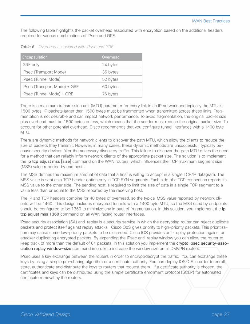
The following table highlights the packet overhead associated with encryption based on the additional headers required for various combinations of IPsec and GRE.
Table 6 Overhead associated with IPsec and GRE
Encapsulation Overhead
GRE only 24 bytes
IPsec (Transport Mode) 36 bytes
IPsec (Tunnel Mode) 52 bytes
IPsec (Transport Mode) + GRE 60 bytes
IPsec (Tunnel Mode) + GRE 76 bytes
There is a maximum transmission unit (MTU) parameter for every link in an IP network and typically the MTU is 1500 bytes. IP packets larger than 1500 bytes must be fragmented when transmitted across these links. Frag-mentation is not desirable and can impact network performance. To avoid fragmentation, the original packet size plus overhead must be 1500 bytes or less, which means that the sender must reduce the original packet size. To account for other potential overhead, Cisco recommends that you configure tunnel interfaces with a 1400 byte MTU.
There are dynamic methods for network clients to discover the path MTU, which allow the clients to reduce the size of packets they transmit. However, in many cases, these dynamic methods are unsuccessful, typically be-cause security devices filter the necessary discovery traffic. This failure to discover the path MTU drives the need for a method that can reliably inform network clients of the appropriate packet size. The solution is to implement the ip tcp adjust mss [size] command on the WAN routers, which influences the TCP maximum segment size (MSS) value reported by end hosts.
The MSS defines the maximum amount of data that a host is willing to accept in a single TCP/IP datagram. The MSS value is sent as a TCP header option only in TCP SYN segments. Each side of a TCP connection reports its MSS value to the other side. The sending host is required to limit the size of data in a single TCP segment to a value less than or equal to the MSS reported by the receiving host.
The IP and TCP headers combine for 40 bytes of overhead, so the typical MSS value reported by network cli-ents will be 1460. This design includes encrypted tunnels with a 1400 byte MTU, so the MSS used by endpoints should be configured to be 1360 to minimize any impact of fragmentation. In this solution, you implement the ip tcp adjust mss 1360 command on all WAN facing router interfaces.
IPsec security association (SA) anti-replay is a security service in which the decrypting router can reject duplicate packets and protect itself against replay attacks. Cisco QoS gives priority to high-priority packets. This prioritiza-tion may cause some low-priority packets to be discarded. Cisco IOS provides anti-replay protection against an attacker duplicating encrypted packets. By expanding the IPsec anti-replay window you can allow the router to keep track of more than the default of 64 packets. In this solution you implement the crypto ipsec security-asso-ciation replay window-size command in order to increase the window size on all DMVPN routers.
IPsec uses a key exchange between the routers in order to encrypt/decrypt the traffic. You can exchange these keys by using a simple pre-sharing algorithm or a certificate authority. You can deploy IOS-CA in order to enroll, store, authenticate and distribute the keys to routers that request them. If a certificate authority is chosen, the certificates and keys can be distributed using the simple certificate enrollment protocol (SCEP) for automated certificate retrieval by the routers.
page 28Cisco Validated Design
IWAN Best Practices
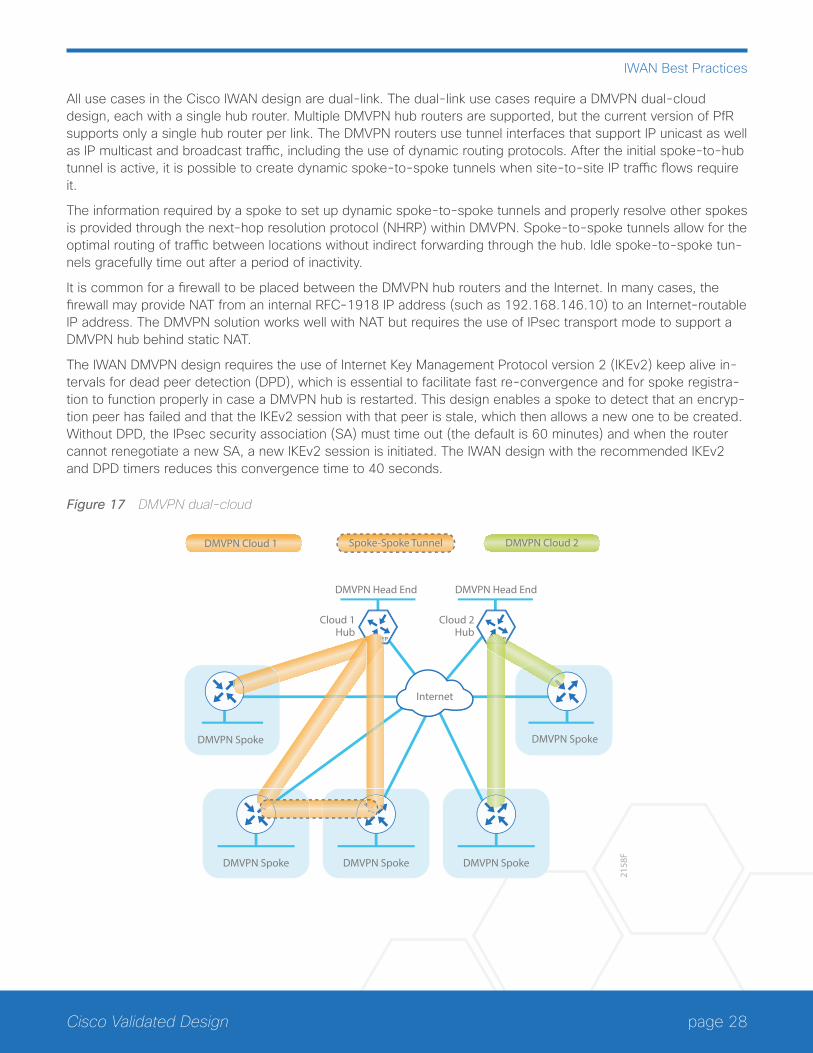
All use cases in the Cisco IWAN design are dual-link. The dual-link use cases require a DMVPN dual-cloud design, each with a single hub router. Multiple DMVPN hub routers are supported, but the current version of PfR supports only a single hub router per link. The DMVPN routers use tunnel interfaces that support IP unicast as well as IP multicast and broadcast traffic, including the use of dynamic routing protocols. After the initial spoke-to-hub tunnel is active, it is possible to create dynamic spoke-to-spoke tunnels when site-to-site IP traffic flows require it.
The information required by a spoke to set up dynamic spoke-to-spoke tunnels and properly resolve other spokes is provided through the next-hop resolution protocol (NHRP) within DMVPN. Spoke-to-spoke tunnels allow for the optimal routing of traffic between locations without indirect forwarding through the hub. Idle spoke-to-spoke tun-nels gracefully time out after a period of inactivity.
It is common for a firewall to be placed between the DMVPN hub routers and the Internet. In many cases, the firewall may provide NAT from an internal RFC-1918 IP address (such as 192.168.146.10) to an Internet-routable IP address. The DMVPN solution works well with NAT but requires the use of IPsec transport mode to support a DMVPN hub behind static NAT.
The IWAN DMVPN design requires the use of Internet Key Management Protocol version 2 (IKEv2) keep alive in-tervals for dead peer detection (DPD), which is essential to facilitate fast re-convergence and for spoke registra-tion to function properly in case a DMVPN hub is restarted. This design enables a spoke to detect that an encryp-tion peer has failed and that the IKEv2 session with that peer is stale, which then allows a new one to be created. Without DPD, the IPsec security association (SA) must time out (the default is 60 minutes) and when the router cannot renegotiate a new SA, a new IKEv2 session is initiated. The IWAN design with the recommended IKEv2 and DPD timers reduces this convergence time to 40 seconds.
Figure 17 DMVPN dual-cloud
2158
F
DMVPN Spoke
DMVPN Spoke DMVPN Spoke
DMVPN Spoke
DMVPN Head End
Cloud 1Hub
Cloud 2Hub
DMVPN Head End
DMVPN Spoke
DMVPN Cloud 1 DMVPN Cloud 2
Internet
Spoke-Spoke Tunnel
page 29Cisco Validated Design
IWAN Best Practices
One of the key benefits of the DMVPN solution is that the spoke routers can use dynamically assigned addresses, often using DHCP from an Internet provider. The spoke routers can leverage an Internet default route for reach-ability to the hub routers and also other spoke addresses.
The DMVPN hub routers have static IP addresses assigned to their public-facing interfaces. This configuration is es-sential for proper operation as each of the spoke routers have these IP addresses embedded in their configurations.
DMVPN HUB ROUTERSThe most critical devices are the WAN routers that are responsible for reliable IP forwarding and QoS. The amount of bandwidth required at each site determines which model of router to use. The IWAN Hybrid and Dual Inter-net designs both require dual WAN aggregation routers to support the pair of DMVPN clouds that are required in order to provide resilient connections to all of the remote sites.
DMVPN SPOKE ROUTER SELECTIONThe actual WAN remote-site routing platforms remain unspecified because the specification is tied closely to the bandwidth required for a location and the potential requirement for the use of service module slots. The ability to implement this solution with a variety of potential router choices is one of the benefits of a modular design approach.
There are many factors to consider in the selection of the WAN remote-site routers. Among those, and key to the initial deployment, is the ability to process the expected amount and type of traffic. You also need to make sure that you have enough interfaces, enough module slots, and a properly licensed Cisco IOS Software image that supports the set of features that is required by the topology.
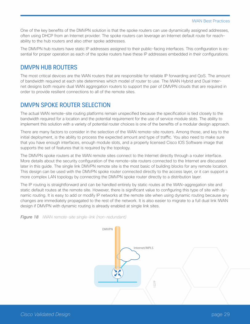
The DMVPN spoke routers at the WAN remote sites connect to the Internet directly through a router interface. More details about the security configuration of the remote-site routers connected to the Internet are discussed later in this guide. The single link DMVPN remote site is the most basic of building blocks for any remote location. This design can be used with the DMVPN spoke router connected directly to the access layer, or it can support a more complex LAN topology by connecting the DMVPN spoke router directly to a distribution layer.
The IP routing is straightforward and can be handled entirely by static routes at the WAN-aggregation site and static default routes at the remote site. However, there is significant value to configuring this type of site with dy-namic routing. It is easy to add or modify IP networks at the remote site when using dynamic routing because any changes are immediately propagated to the rest of the network. It is also easier to migrate to a full dual link IWAN design if DMVPN with dynamic routing is already enabled at single link sites.
Figure 18 IWAN remote-site single-link (non-redundant)
Internet/MPLS
DMVPN
1227
F
page 30Cisco Validated Design
IWAN Best Practices
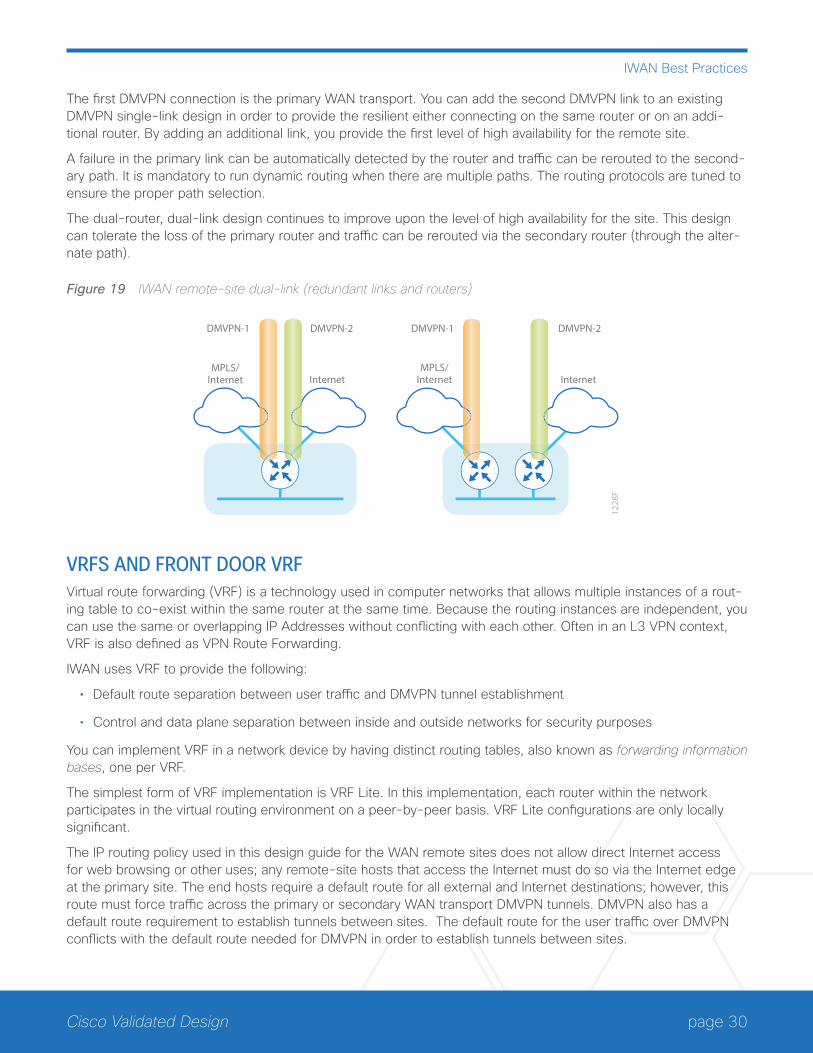
The first DMVPN connection is the primary WAN transport. You can add the second DMVPN link to an existing DMVPN single-link design in order to provide the resilient either connecting on the same router or on an addi-tional router. By adding an additional link, you provide the first level of high availability for the remote site.
A failure in the primary link can be automatically detected by the router and traffic can be rerouted to the second-ary path. It is mandatory to run dynamic routing when there are multiple paths. The routing protocols are tuned to ensure the proper path selection.
The dual-router, dual-link design continues to improve upon the level of high availability for the site. This design can tolerate the loss of the primary router and traffic can be rerouted via the secondary router (through the alter-nate path).
Figure 19 IWAN remote-site dual-link (redundant links and routers)
InternetMPLS/
Internet
DMVPN-1 DMVPN-2 DMVPN-1
Internet
DMVPN-2
1228
F
MPLS/Internet
VRFS AND FRONT DOOR VRFVirtual route forwarding (VRF) is a technology used in computer networks that allows multiple instances of a rout-ing table to co-exist within the same router at the same time. Because the routing instances are independent, you can use the same or overlapping IP Addresses without conflicting with each other. Often in an L3 VPN context, VRF is also defined as VPN Route Forwarding.
IWAN uses VRF to provide the following:
• Default route separation between user traffic and DMVPN tunnel establishment
• Control and data plane separation between inside and outside networks for security purposes
You can implement VRF in a network device by having distinct routing tables, also known as forwarding information bases, one per VRF.
The simplest form of VRF implementation is VRF Lite. In this implementation, each router within the network participates in the virtual routing environment on a peer-by-peer basis. VRF Lite configurations are only locally significant.
The IP routing policy used in this design guide for the WAN remote sites does not allow direct Internet access for web browsing or other uses; any remote-site hosts that access the Internet must do so via the Internet edge at the primary site. The end hosts require a default route for all external and Internet destinations; however, this route must force traffic across the primary or secondary WAN transport DMVPN tunnels. DMVPN also has a default route requirement to establish tunnels between sites. The default route for the user traffic over DMVPN conflicts with the default route needed for DMVPN in order to establish tunnels between sites.
page 31Cisco Validated Design
IWAN Best Practices
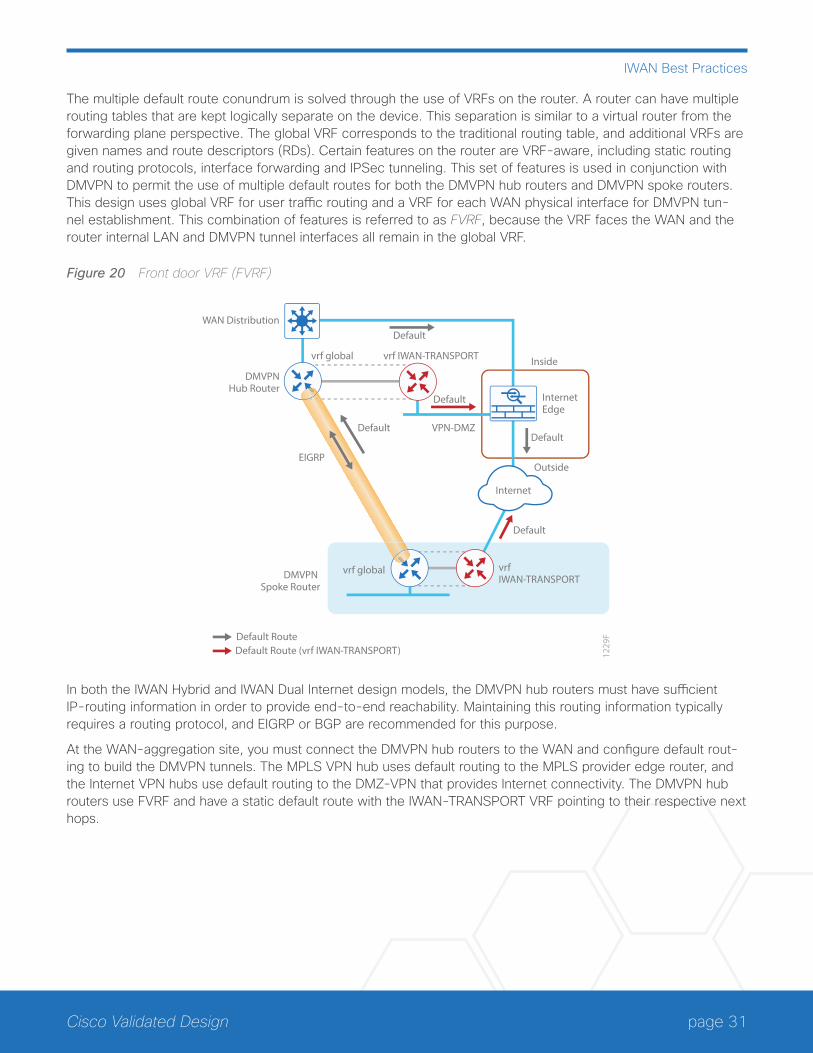
The multiple default route conundrum is solved through the use of VRFs on the router. A router can have multiple routing tables that are kept logically separate on the device. This separation is similar to a virtual router from the forwarding plane perspective. The global VRF corresponds to the traditional routing table, and additional VRFs are given names and route descriptors (RDs). Certain features on the router are VRF-aware, including static routing and routing protocols, interface forwarding and IPSec tunneling. This set of features is used in conjunction with DMVPN to permit the use of multiple default routes for both the DMVPN hub routers and DMVPN spoke routers. This design uses global VRF for user traffic routing and a VRF for each WAN physical interface for DMVPN tun-nel establishment. This combination of features is referred to as FVRF, because the VRF faces the WAN and the router internal LAN and DMVPN tunnel interfaces all remain in the global VRF.
Figure 20 Front door VRF (FVRF)
1229
F
Inside
Outside
InternetEdge
Default
DefaultDefault
VPN-DMZ
Default
Default
Default Route
DMVPNHub Router
WAN Distribution
vrf global vrf IWAN-TRANSPORT
vrf global vrf IWAN-TRANSPORT
Default Route (vrf IWAN-TRANSPORT)
DMVPN Spoke Router
Internet
EIGRP
In both the IWAN Hybrid and IWAN Dual Internet design models, the DMVPN hub routers must have sufficient IP-routing information in order to provide end-to-end reachability. Maintaining this routing information typically requires a routing protocol, and EIGRP or BGP are recommended for this purpose.
At the WAN-aggregation site, you must connect the DMVPN hub routers to the WAN and configure default rout-ing to build the DMVPN tunnels. The MPLS VPN hub uses default routing to the MPLS provider edge router, and the Internet VPN hubs use default routing to the DMZ-VPN that provides Internet connectivity. The DMVPN hub routers use FVRF and have a static default route with the IWAN-TRANSPORT VRF pointing to their respective next hops.
page 32Cisco Validated Design
IWAN Best Practices
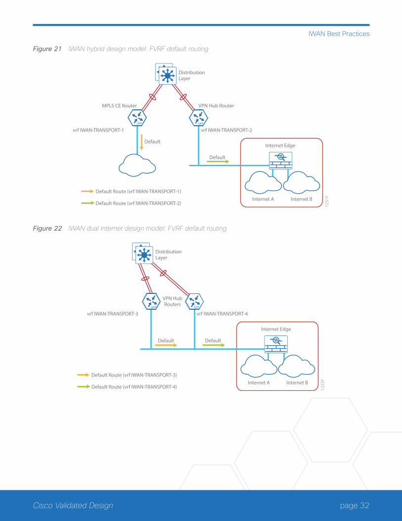
Figure 21 IWAN hybrid design model: FVRF default routing
1231
F
DistributionLayer
Internet Edge
Internet A Internet B
VPN Hub Router
vrf IWAN-TRANSPORT-2vrf IWAN-TRANSPORT-1
Default
Default
MPLS CE Router
Default Route (vrf IWAN-TRANSPORT-1)
Default Route (vrf IWAN-TRANSPORT-2)
Figure 22 IWAN dual Internet design model: FVRF default routing
1232
F
DistributionLayer
Internet Edge
Internet A Internet B
VPN HubRouters
vrf IWAN-TRANSPORT-4vrf IWAN-TRANSPORT-3
Default
Default Route (vrf IWAN-TRANSPORT-3)
Default Route (vrf IWAN-TRANSPORT-4)
Default
page 33Cisco Validated Design
Summary for IWAN
Summary for IWANCisco enterprise IWAN architectures are proven solutions that scale to all remote-site sizes over MPLS and Internet transports. With rich application and security services on a single platform, IT can scale to hundreds of sites. Also, customers can maintain granular control, from the remote site, to the data center, and out to the public cloud. The traffic is dynamically routed based on application, endpoint, and network conditions in order to help ensure the best user experience. IT can confidently roll out critical business services such as consolidated data centers, SaaS, IP telephony, and video without overwhelming the WAN.
page 34Cisco Validated Design
Traditional WAN Introduction
Traditional WAN Introduction The enterprise WAN architecture interconnects remote-site LANs to a primary site LAN or data center by us-ing a variety of WAN technologies, including MPLS, Layer 2 WAN, and virtual private network (VPN) WAN over the Internet. CVD enterprise WAN is designed to support multiple resiliency options depending on the business requirements for the remote sites.
The WAN design methodology provides network access for remote sites that have wired and wireless users, ranging from small remote sites with a few connected users to large sites with up to 5,000 connected users.
Cisco tests network and user devices connected together to simulate an end-to-end deployment for your orga-nization. This solution-level approach reduces the risk of interoperability problems between different technologies and components, allowing the customer to select the parts needed to solve a business problem. Where appropri-ate, the architecture provides multiple options based on network scalability or service-level requirements.
Cisco designed, built, and tested this reference network architecture with the following goals:
• Ease of deployment—Organizations can deploy the solution consistently across all products included in the design. The reference configurations used in the deployment represent a best-practice methodology that enables a fast and resilient deployment.
• Flexibility and scalability—The architecture is modular so that organizations can select what they need when they need it, and it is designed to grow with the organization without requiring costly forklift upgrades.
• Resiliency and security—The design removes network borders in order to increase usability while protecting user traffic. It also keeps the network operational even during attacks or unplanned outages.
• Ease of management—Deployment and configuration guidance includes configuration examples of manage-ment by a network management system or by unique network element managers.
• Advanced technology ready—The reference network foundation allows easier implementation of advanced technologies such as collaboration.
BUSINESS USE CASES FOR TRADITIONAL WANFor remote-site users to effectively support the business, organizations require that the WAN provide services with sufficient performance and reliability. Because most of the applications and services that the remote-site worker uses are centrally located or hosted in the cloud, the WAN design must provide a common resource ac-cess experience to the workforce regardless of location. The following use cases are relevant for many organiza-tions.
page 35Cisco Validated Design
Traditional WAN Introduction
Use Case: Site-to-Site Communications Using MPLS ServicesOrganizations deploy MPLS WAN in order to connect remote locations over private cloud Layer 3 VPN-based provider managed MPLS services.
This design enables the following network capabilities:
• IP any-to-any WAN connectivity for up to 500 remote sites and one or two central hub site locations
• Deployment of single or dual MPLS service providers for resiliency using single or dual routers in remote site locations
• Static routing or dynamic border gateway protocol (BGP) peering with the MPLS service provider for site-to-site communications
• Support for Layer 2 or Layer 3 distribution switching designs
• Support for IP multicast using multicast VPN (mVPN) service provider-based offering
• QoS for WAN traffic such as voice, video, critical data applications, bulk data applications, and management traffic on the network
Use Case: Site–to-Site Communications Using Layer 2 WAN ServicesOrganizations deploy Layer 2 WAN in order to connect remote office locations over private cloud Layer 2 ser-vices. These WAN services can include provider-managed Ethernet over MPLS (EoMPLS) and virtual private LAN service (VPLS).
This design enables the following network capabilities:
• WAN connectivity for up to 100 remote site locations
• Layer 2 adjacency between customer edge (CE) routers supporting 802.1Q and other Layer 2 protocols
• Direct CE-to-CE router peering with an Interior Gateway Protocol (IGP), such as Enhanced Interior Gateway Routing Protocol (EIGRP), transparent to the MPLS service provider
• Simplified IP multicast deployments, transparent to the MPLS service provider
• QoS for WAN traffic such as voice, video, critical data applications, bulk data applications, and management traffic
Use Case: Site-to-Site Connectivity Using 4G LTE Wireless ServicesOrganizations deploy 4G LTE WAN in order to connect remote sites over 4G LTE wireless services as a primary or secondary WAN solution with secure communications between sites.
This design enables the following network capabilities:
• 4G LTE wireless service for primary remote site WAN connectivity
• 4G LTE encryption services using Cisco Dynamic Multipoint Virtual Private Network (DMVPN)
• 4G LTE wireless service as a backup to the primary WAN service
• QoS for WAN traffic such as voice, video, critical data applications, bulk data applications, and management traffic
page 36Cisco Validated Design
Traditional WAN Introduction
Use Case: Secure Site-to-Site WAN Communications Using MPLS ServicesOrganizations require encryption in order to secure communications between sites over private cloud services such as provider-managed MPLS.
This Group Encrypted Transport VPN (GET VPN) design enables the following network capabilities:
• Any-to-any secure encrypted communications well suited for MPLS-based WAN services, for up to 500 locations
• Encrypted traffic that follows the native routing path directly between remote sites, rather than following a tunnel overlay model
• Encryption services, with single or dual MPLS service providers, that support resilient designs using single or dual routers in remote-site locations
• Support for IP Multicast, allowing multicast replication after encryption within the service provider network
• Compatibility with WAN transport solutions that do not perform network address translation (NAT) after en-cryption
• QoS for WAN traffic such as voice, video, critical data applications, bulk data applications and management traffic
Use Case: Secure Site-to-Site WAN Communications Using Internet ServicesOrganizations deploy Internet WAN in order to connect remote sites over public cloud Internet services with se-cure communications between sites.
This DMVPN design enables the following network capabilities:
• Secure, encrypted communications for Internet-based WAN solutions for up to 500 locations by using a hub-and-spoke tunnel overlay configuration
• Deployment as a secondary connectivity solution for resiliency, providing backup to private MPLS WAN ser-vice by using single or dual routers in remote locations
• Support for IP Multicast, replication performed on core, hub-site routers
• Compatibility with public cloud solutions where NAT is implemented
• Best-effort quality of service for WAN traffic such as voice, video, critical data applications, bulk data applica-tions, and management traffic
page 37Cisco Validated Design
Traditional WAN Architecture
Traditional WAN Architecture Many businesses have remote locations that depend entirely on applications hosted in a centralized data center. If a WAN outage occurs, these remote locations are essentially offline and they are unable to process transactions or support other types of business services. It is critical to provide reliable connectivity to these locations.
The demand for WAN bandwidth continues to increase, and there has been a recent trend towards using Ether-net as the WAN access media in order to deliver higher bandwidth. Even with the increased amount of bandwidth available to connect remote sites today, there are performance-sensitive applications affected by jitter, delay, and packet loss. It is the function of the network foundation to provide an efficient, fault-tolerant transport that can dif-ferentiate application traffic to make intelligent load-sharing decisions when the network is temporarily congested. Regardless of the chosen WAN technology, the network must provide intelligent prioritization and queuing of traf-fic along the most efficient route possible.
WAN-AGGREGATION DESIGN The CVD enterprise WAN design does not take a “one size fits all” approach. Cisco developed a set of WAN design models based on scaling requirements and other considerations including resiliency, the need for future growth, regional availability of WAN services, and ease of operation. Cisco designed and tested the complete CVD enterprise WAN to accommodate the use of multiple concurrent design models but also to support the us-age of individual design models.
The approach to platform selection is straightforward. You determine which models of router to use by the amount of bandwidth required at the WAN-aggregation site. You determine whether to implement a single router or dual router by the number of carriers and WAN transports that are required in order to provide connections to all of the remote sites.
The available design models can be grouped together in a number of ways to provide connectivity to the required numbers and types of remote sites. All design models provide a high level of performance and services. To il-lustrate the wide range of scale that CVD enterprise WAN provides you can compare two combinations of design models.
The following figures show a CVD enterprise WAN implemented using the lowest and highest scaling design models.
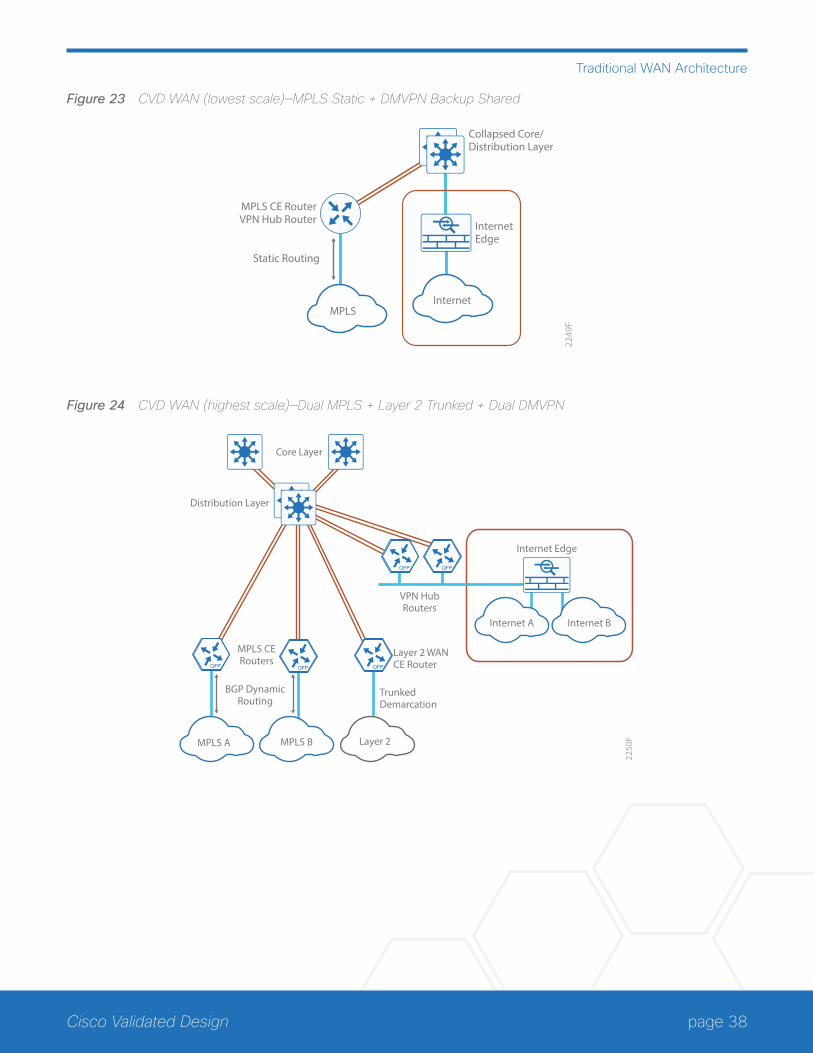
page 38Cisco Validated Design
Traditional WAN Architecture
Figure 23 CVD WAN (lowest scale)—MPLS Static + DMVPN Backup Shared
2249
F
InternetEdge
MPLS
MPLS CE RouterVPN Hub Router
Collapsed Core/Distribution Layer
Static Routing
Internet
Figure 24 CVD WAN (highest scale)—Dual MPLS + Layer 2 Trunked + Dual DMVPN
Internet Edge
VPN HubRouters
Layer 2 WANCE Router
TrunkedDemarcation
Core Layer
Distribution Layer
MPLS CERouters
2250
F
BGP DynamicRouting
MPLS A Layer 2MPLS B
Internet A Internet B
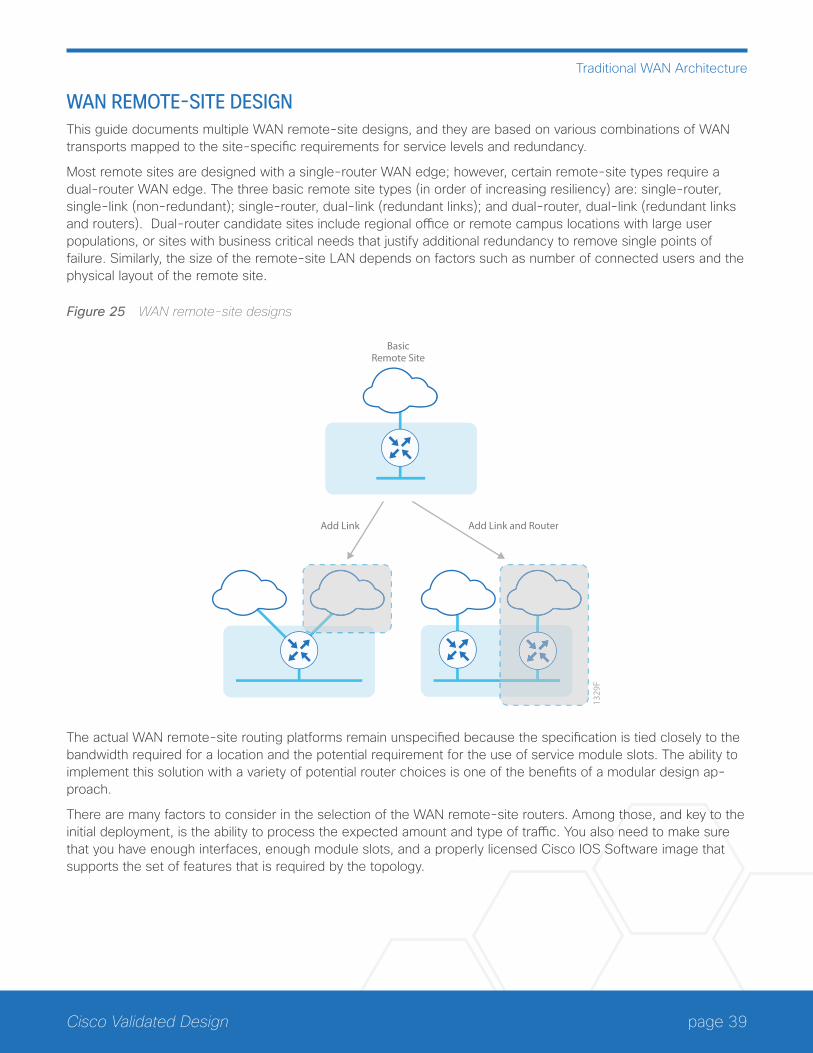
page 39Cisco Validated Design
Traditional WAN Architecture
WAN REMOTE-SITE DESIGNThis guide documents multiple WAN remote-site designs, and they are based on various combinations of WAN transports mapped to the site-specific requirements for service levels and redundancy.
Most remote sites are designed with a single-router WAN edge; however, certain remote-site types require a dual-router WAN edge. The three basic remote site types (in order of increasing resiliency) are: single-router, single-link (non-redundant); single-router, dual-link (redundant links); and dual-router, dual-link (redundant links and routers). Dual-router candidate sites include regional office or remote campus locations with large user populations, or sites with business critical needs that justify additional redundancy to remove single points of failure. Similarly, the size of the remote-site LAN depends on factors such as number of connected users and the physical layout of the remote site.
Figure 25 WAN remote-site designs
Add Link
1329
F
BasicRemote Site
Add Link and Router
The actual WAN remote-site routing platforms remain unspecified because the specification is tied closely to the bandwidth required for a location and the potential requirement for the use of service module slots. The ability to implement this solution with a variety of potential router choices is one of the benefits of a modular design ap-proach.
There are many factors to consider in the selection of the WAN remote-site routers. Among those, and key to the initial deployment, is the ability to process the expected amount and type of traffic. You also need to make sure that you have enough interfaces, enough module slots, and a properly licensed Cisco IOS Software image that supports the set of features that is required by the topology.
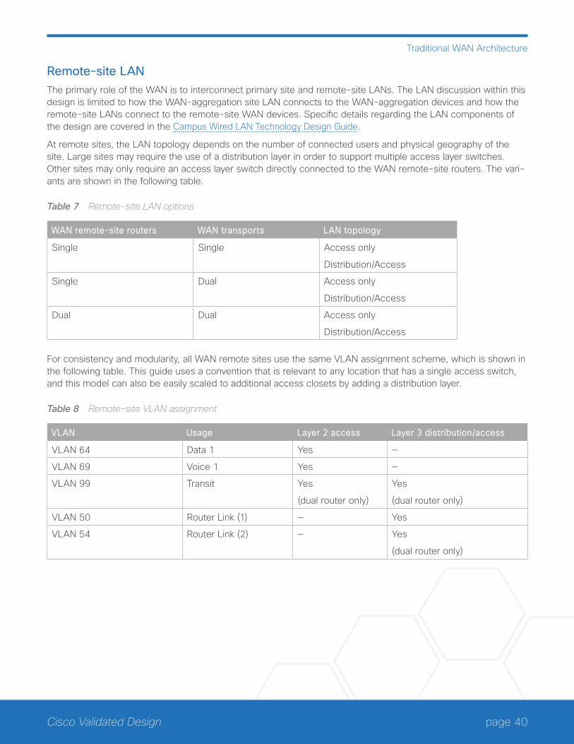
page 40Cisco Validated Design
Traditional WAN Architecture
Remote-site LANThe primary role of the WAN is to interconnect primary site and remote-site LANs. The LAN discussion within this design is limited to how the WAN-aggregation site LAN connects to the WAN-aggregation devices and how the remote-site LANs connect to the remote-site WAN devices. Specific details regarding the LAN components of the design are covered in the Campus Wired LAN Technology Design Guide.
At remote sites, the LAN topology depends on the number of connected users and physical geography of the site. Large sites may require the use of a distribution layer in order to support multiple access layer switches. Other sites may only require an access layer switch directly connected to the WAN remote-site routers. The vari-ants are shown in the following table.
Table 7 Remote-site LAN options
WAN remote-site routers WAN transports LAN topology
Single Single Access only
Distribution/Access
Single Dual Access only
Distribution/Access
Dual Dual Access only
Distribution/Access
For consistency and modularity, all WAN remote sites use the same VLAN assignment scheme, which is shown in the following table. This guide uses a convention that is relevant to any location that has a single access switch, and this model can also be easily scaled to additional access closets by adding a distribution layer.
Table 8 Remote-site VLAN assignment
VLAN Usage Layer 2 access Layer 3 distribution/access
VLAN 64 Data 1 Yes —
VLAN 69 Voice 1 Yes —
VLAN 99 Transit Yes
(dual router only)
Yes
(dual router only)
VLAN 50 Router Link (1) — Yes
VLAN 54 Router Link (2) — Yes
(dual router only)
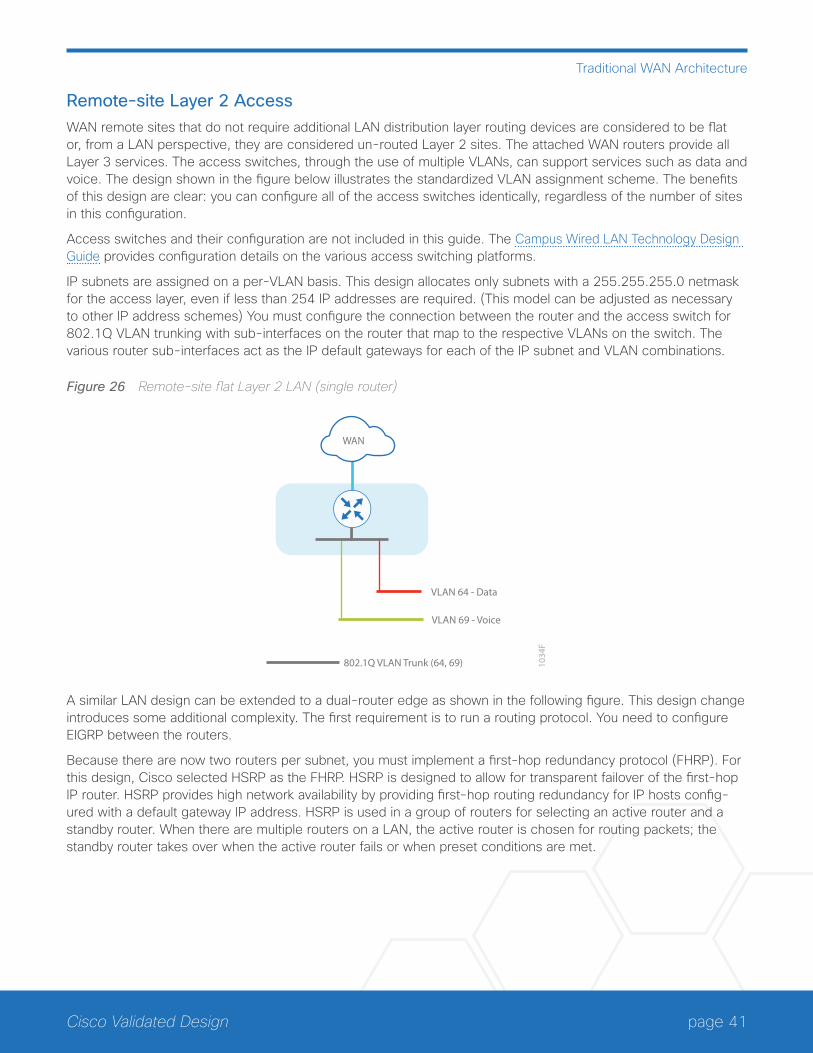
page 41Cisco Validated Design
Traditional WAN Architecture
Remote-site Layer 2 AccessWAN remote sites that do not require additional LAN distribution layer routing devices are considered to be flat or, from a LAN perspective, they are considered un-routed Layer 2 sites. The attached WAN routers provide all Layer 3 services. The access switches, through the use of multiple VLANs, can support services such as data and voice. The design shown in the figure below illustrates the standardized VLAN assignment scheme. The benefits of this design are clear: you can configure all of the access switches identically, regardless of the number of sites in this configuration.
Access switches and their configuration are not included in this guide. The Campus Wired LAN Technology Design Guide provides configuration details on the various access switching platforms.
IP subnets are assigned on a per-VLAN basis. This design allocates only subnets with a 255.255.255.0 netmask for the access layer, even if less than 254 IP addresses are required. (This model can be adjusted as necessary to other IP address schemes) You must configure the connection between the router and the access switch for 802.1Q VLAN trunking with sub-interfaces on the router that map to the respective VLANs on the switch. The various router sub-interfaces act as the IP default gateways for each of the IP subnet and VLAN combinations.
Figure 26 Remote-site flat Layer 2 LAN (single router)
VLAN 64 - Data
802.1Q VLAN Trunk (64, 69)
VLAN 69 - Voice
1034
F
WAN
A similar LAN design can be extended to a dual-router edge as shown in the following figure. This design change introduces some additional complexity. The first requirement is to run a routing protocol. You need to configure EIGRP between the routers.
Because there are now two routers per subnet, you must implement a first-hop redundancy protocol (FHRP). For this design, Cisco selected HSRP as the FHRP. HSRP is designed to allow for transparent failover of the first-hop IP router. HSRP provides high network availability by providing first-hop routing redundancy for IP hosts config-ured with a default gateway IP address. HSRP is used in a group of routers for selecting an active router and a standby router. When there are multiple routers on a LAN, the active router is chosen for routing packets; the standby router takes over when the active router fails or when preset conditions are met.
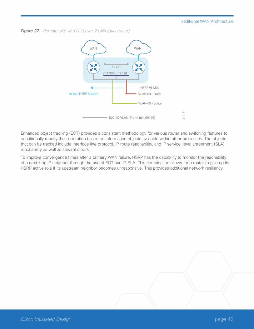
page 42Cisco Validated Design
Traditional WAN Architecture
Figure 27 Remote-site with flat Layer 2 LAN (dual router)
WAN WAN
Active HSRP Router VLAN 64 - Data
VLAN99 - Transit
802.1Q VLAN Trunk (64, 69, 99)
VLAN 69 - Voice
2141
F
HSRP VLANs
EIGRP
Enhanced object tracking (EOT) provides a consistent methodology for various router and switching features to conditionally modify their operation based on information objects available within other processes. The objects that can be tracked include interface line protocol, IP route reachability, and IP service-level agreement (SLA) reachability as well as several others.
To improve convergence times after a primary WAN failure, HSRP has the capability to monitor the reachability of a next-hop IP neighbor through the use of EOT and IP SLA. This combination allows for a router to give up its HSRP active role if its upstream neighbor becomes unresponsive. This provides additional network resiliency.
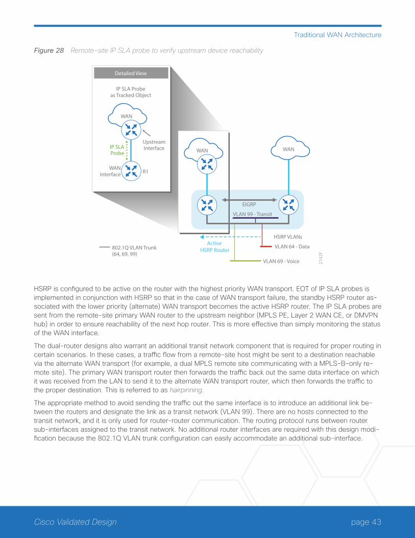
page 43Cisco Validated Design
Traditional WAN Architecture
Figure 28 Remote-site IP SLA probe to verify upstream device reachability
WAN
Active HSRP Router
VLAN 64 - Data
VLAN 99 - Transit
802.1Q VLAN Trunk (64, 69, 99)
VLAN 69 - Voice 2142
F
HSRP VLANs
EIGRP
IP SLAProbe
WANInterface R1
UpstreamInterface
WAN
IP SLA Probeas Tracked Object
Detailed View
WAN
HSRP is configured to be active on the router with the highest priority WAN transport. EOT of IP SLA probes is implemented in conjunction with HSRP so that in the case of WAN transport failure, the standby HSRP router as-sociated with the lower priority (alternate) WAN transport becomes the active HSRP router. The IP SLA probes are sent from the remote-site primary WAN router to the upstream neighbor (MPLS PE, Layer 2 WAN CE, or DMVPN hub) in order to ensure reachability of the next hop router. This is more effective than simply monitoring the status of the WAN interface.
The dual-router designs also warrant an additional transit network component that is required for proper routing in certain scenarios. In these cases, a traffic flow from a remote-site host might be sent to a destination reachable via the alternate WAN transport (for example, a dual MPLS remote site communicating with a MPLS-B-only re-mote site). The primary WAN transport router then forwards the traffic back out the same data interface on which it was received from the LAN to send it to the alternate WAN transport router, which then forwards the traffic to the proper destination. This is referred to as hairpinning.
The appropriate method to avoid sending the traffic out the same interface is to introduce an additional link be-tween the routers and designate the link as a transit network (VLAN 99). There are no hosts connected to the transit network, and it is only used for router-router communication. The routing protocol runs between router sub-interfaces assigned to the transit network. No additional router interfaces are required with this design modi-fication because the 802.1Q VLAN trunk configuration can easily accommodate an additional sub-interface.
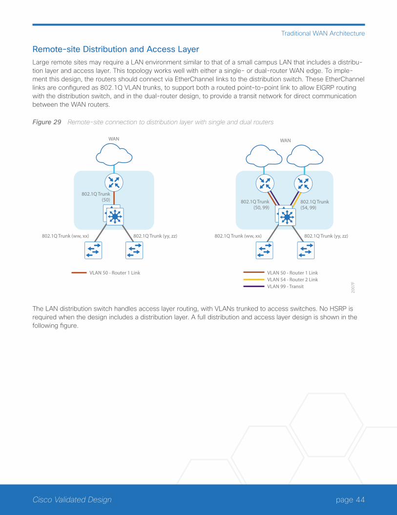
page 44Cisco Validated Design
Traditional WAN Architecture
Remote-site Distribution and Access LayerLarge remote sites may require a LAN environment similar to that of a small campus LAN that includes a distribu-tion layer and access layer. This topology works well with either a single- or dual-router WAN edge. To imple-ment this design, the routers should connect via EtherChannel links to the distribution switch. These EtherChannel links are configured as 802.1Q VLAN trunks, to support both a routed point-to-point link to allow EIGRP routing with the distribution switch, and in the dual-router design, to provide a transit network for direct communication between the WAN routers.
Figure 29 Remote-site connection to distribution layer with single and dual routers
2007
F
WAN WAN
802.1Q Trunk(50)
802.1Q Trunk (ww, xx) 802.1Q Trunk (yy, zz) 802.1Q Trunk (ww, xx)
802.1Q Trunk(50, 99)
802.1Q Trunk(54, 99)
VLAN 50 - Router 1 LinkVLAN 54 - Router 2 LinkVLAN 99 - Transit
VLAN 50 - Router 1 Link
802.1Q Trunk (yy, zz)
The LAN distribution switch handles access layer routing, with VLANs trunked to access switches. No HSRP is required when the design includes a distribution layer. A full distribution and access layer design is shown in the following figure.
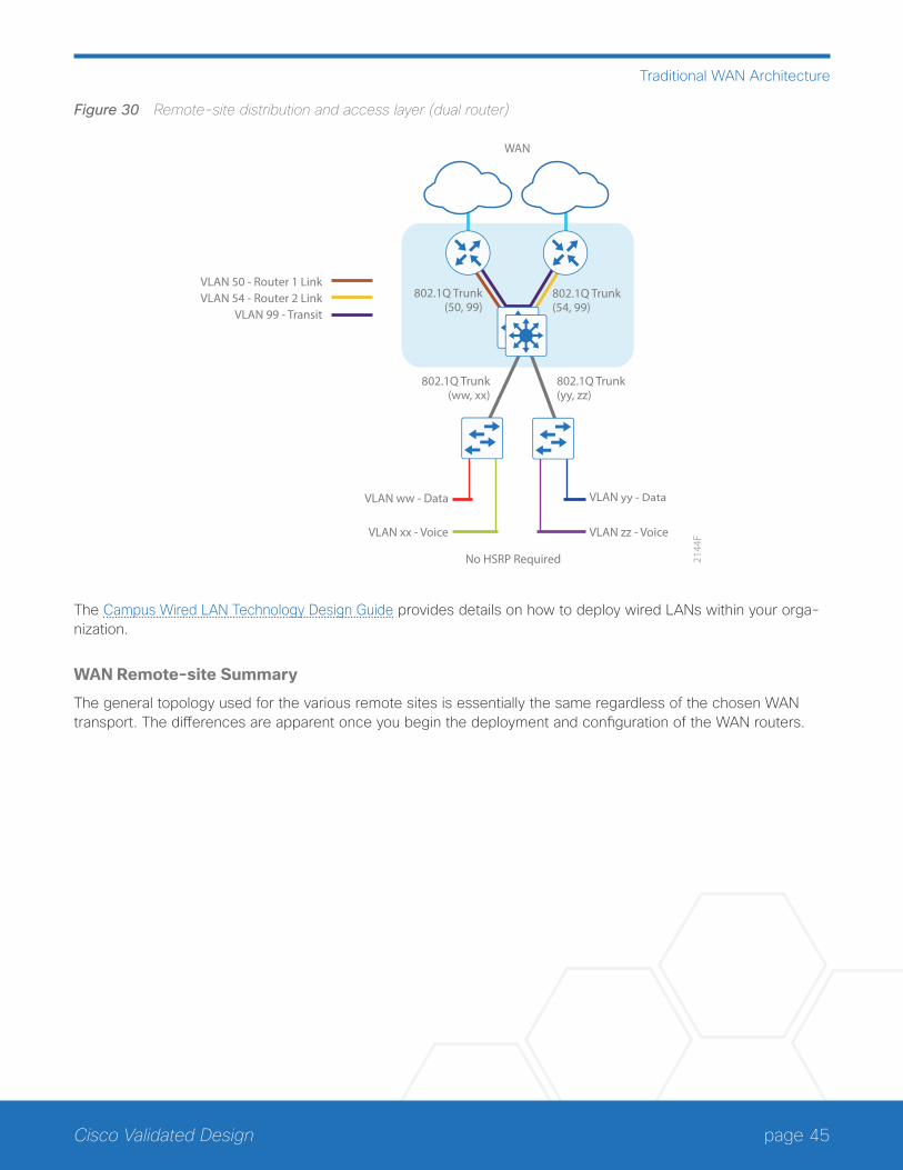
page 45Cisco Validated Design
Traditional WAN Architecture
Figure 30 Remote-site distribution and access layer (dual router)
2144
F
WAN
VLAN 50 - Router 1 Link
802.1Q Trunk(ww, xx)
VLAN ww - Data
VLAN xx - Voice
VLAN yy - Data
VLAN zz - Voice
No HSRP Required
802.1Q Trunk(yy, zz)
802.1Q Trunk(50, 99)
802.1Q Trunk(54, 99)
VLAN 54 - Router 2 LinkVLAN 99 - Transit
The Campus Wired LAN Technology Design Guide provides details on how to deploy wired LANs within your orga-nization.
WAN Remote-site Summary
The general topology used for the various remote sites is essentially the same regardless of the chosen WAN transport. The differences are apparent once you begin the deployment and configuration of the WAN routers.
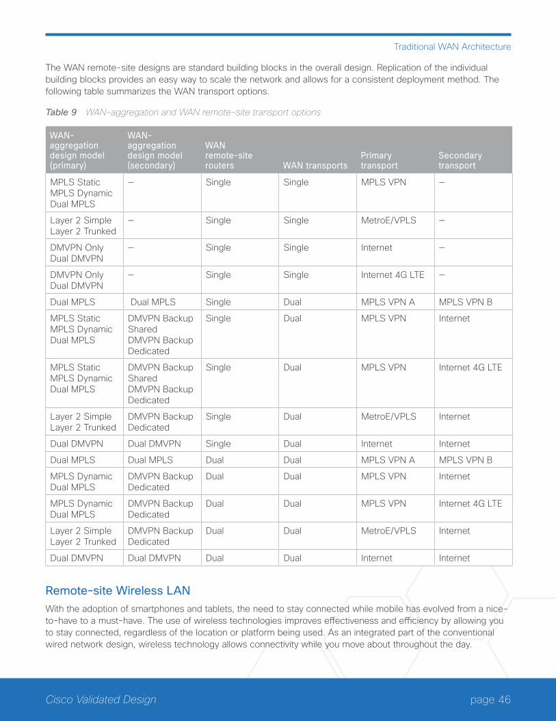
page 46Cisco Validated Design
Traditional WAN Architecture
The WAN remote-site designs are standard building blocks in the overall design. Replication of the individual building blocks provides an easy way to scale the network and allows for a consistent deployment method. The following table summarizes the WAN transport options.
Table 9 WAN-aggregation and WAN remote-site transport options
WAN-aggregation design model (primary)
WAN-aggregation design model (secondary)
WAN remote-site routers WAN transports
Primary transport
Secondary transport
MPLS Static MPLS Dynamic Dual MPLS
— Single Single MPLS VPN —
Layer 2 Simple Layer 2 Trunked
— Single Single MetroE/VPLS —
DMVPN Only Dual DMVPN
— Single Single Internet —
DMVPN Only Dual DMVPN
— Single Single Internet 4G LTE —
Dual MPLS Dual MPLS Single Dual MPLS VPN A MPLS VPN B
MPLS Static MPLS Dynamic Dual MPLS
DMVPN Backup Shared DMVPN Backup Dedicated
Single Dual MPLS VPN Internet
MPLS Static MPLS Dynamic Dual MPLS
DMVPN Backup Shared DMVPN Backup Dedicated
Single Dual MPLS VPN Internet 4G LTE
Layer 2 Simple Layer 2 Trunked
DMVPN Backup Dedicated
Single Dual MetroE/VPLS Internet
Dual DMVPN Dual DMVPN Single Dual Internet Internet
Dual MPLS Dual MPLS Dual Dual MPLS VPN A MPLS VPN B
MPLS Dynamic Dual MPLS
DMVPN Backup Dedicated
Dual Dual MPLS VPN Internet
MPLS Dynamic Dual MPLS
DMVPN Backup Dedicated
Dual Dual MPLS VPN Internet 4G LTE
Layer 2 Simple Layer 2 Trunked
DMVPN Backup Dedicated
Dual Dual MetroE/VPLS Internet
Dual DMVPN Dual DMVPN Dual Dual Internet Internet
Remote-site Wireless LANWith the adoption of smartphones and tablets, the need to stay connected while mobile has evolved from a nice-to-have to a must-have. The use of wireless technologies improves effectiveness and efficiency by allowing you to stay connected, regardless of the location or platform being used. As an integrated part of the conventional wired network design, wireless technology allows connectivity while you move about throughout the day.
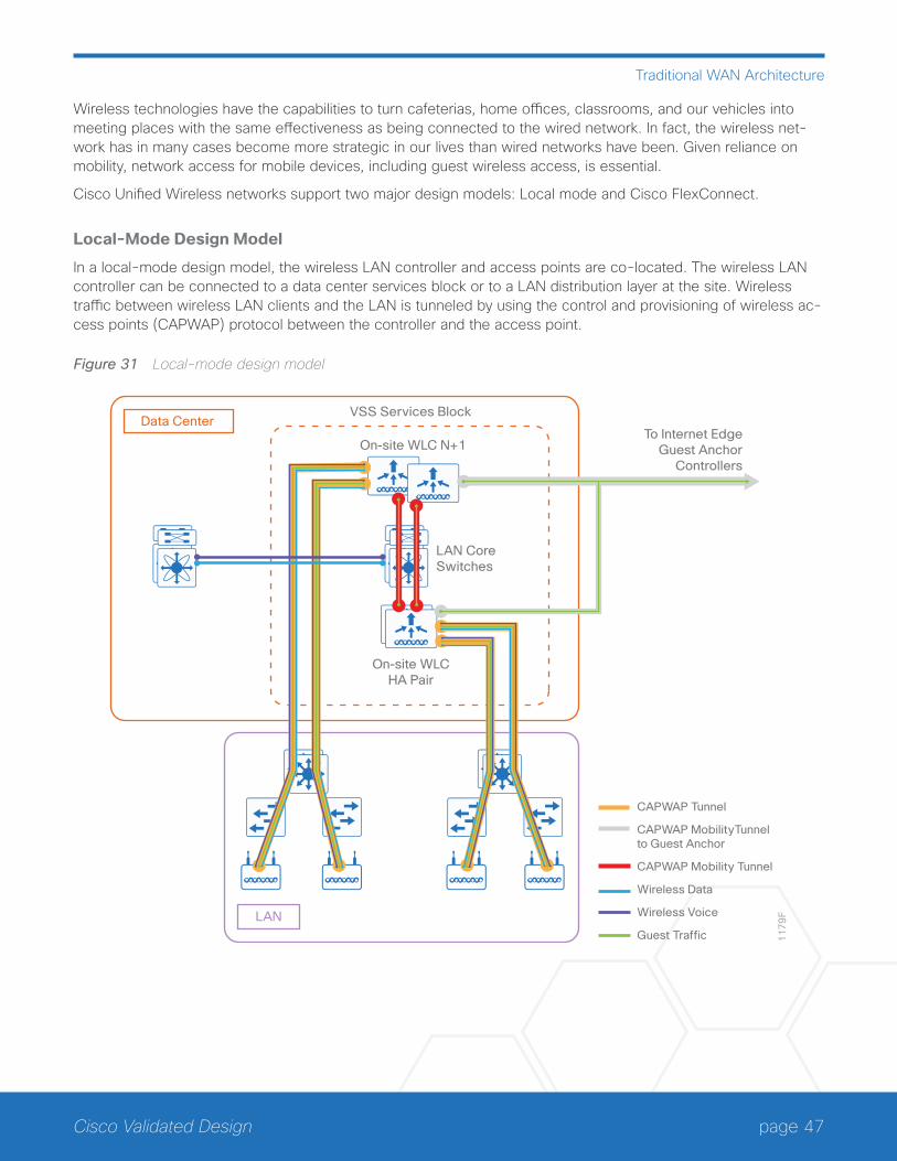
page 47Cisco Validated Design
Traditional WAN Architecture
Wireless technologies have the capabilities to turn cafeterias, home offices, classrooms, and our vehicles into meeting places with the same effectiveness as being connected to the wired network. In fact, the wireless net-work has in many cases become more strategic in our lives than wired networks have been. Given reliance on mobility, network access for mobile devices, including guest wireless access, is essential.
Cisco Unified Wireless networks support two major design models: Local mode and Cisco FlexConnect.
Local-Mode Design Model
In a local-mode design model, the wireless LAN controller and access points are co-located. The wireless LAN controller can be connected to a data center services block or to a LAN distribution layer at the site. Wireless traffic between wireless LAN clients and the LAN is tunneled by using the control and provisioning of wireless ac-cess points (CAPWAP) protocol between the controller and the access point.
Figure 31 Local-mode design model
11
79
FLAN
VSS Services Block
On-site WLC N+1
LAN CoreSwitches
Data Center
On-site WLCHA Pair
To Internet EdgeGuest Anchor
Controllers
CAPWAP Tunnel
CAPWAP MobilityTunnel to Guest Anchor
CAPWAP Mobility Tunnel
Wireless Data
Wireless Voice
Guest Traffic

page 48Cisco Validated Design
Traditional WAN Architecture
A local-mode architecture uses the controller as a single point for managing Layer 2 security and wireless net-work policies. It also enables you to apply services to wired and wireless traffic in a consistent and coordinated fashion.
If any of the following are true at a site, you should deploy a controller locally at the site:
• The site comprises a data center.
• The site has a LAN distribution layer.
• The site has more than 50 access points.
• The site has a WAN latency greater than 100 ms round-trip to a proposed shared controller.
For resiliency, this design uses two wireless LAN controllers for the campus, although you can add more wireless LAN controllers in order to provide additional capacity and resiliency to this design.
Cisco FlexConnect Design Model
Cisco FlexConnect is a wireless solution for most remote-site deployments. It enables organizations to configure and control remote-site access points from the headquarters through the WAN, without deploying a controller in each remote site.
The Cisco FlexConnect access point can switch client data traffic out its local wired interface and can use 802.1Q trunking in order to segment multiple WLANs. The trunk’s native VLAN is used for all CAPWAP communication between the access point and the controller. This mode of operation is referred to as FlexConnect local switching and is the mode of operation described in this guide.
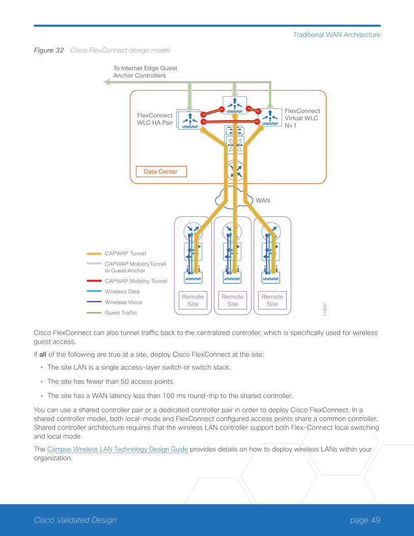
page 49Cisco Validated Design
Traditional WAN Architecture
Figure 32 Cisco FlexConnect design model
11
80
F
WAN
RemoteSite
RemoteSite
RemoteSite
FlexConnectWLC HA Pair
FlexConnectVirtual WLCN+1
Data Center
To Internet Edge GuestAnchor Controllers
CAPWAP Tunnel
CAPWAP MobilityTunnel to Guest Anchor
CAPWAP Mobility Tunnel
Wireless Data
Wireless Voice
Guest Traffic
Cisco FlexConnect can also tunnel traffic back to the centralized controller, which is specifically used for wireless guest access.
If all of the following are true at a site, deploy Cisco FlexConnect at the site:
• The site LAN is a single access-layer switch or switch stack.
• The site has fewer than 50 access points.
• The site has a WAN latency less than 100 ms round-trip to the shared controller.
You can use a shared controller pair or a dedicated controller pair in order to deploy Cisco FlexConnect. In a shared controller model, both local-mode and FlexConnect configured access points share a common controller. Shared controller architecture requires that the wireless LAN controller support both Flex-Connect local switching and local mode.
The Campus Wireless LAN Technology Design Guide provides details on how to deploy wireless LANs within your organization.
page 50Cisco Validated Design
Traditional WAN Architecture
IP MULTICASTIP Multicast allows a single IP data stream to be replicated by the infrastructure (routers and switches) and sent from a single source to multiple receivers. IP Multicast is much more efficient than multiple individual unicast streams or a broadcast stream that would propagate everywhere. IP telephony music on hold (MOH) and IP video broadcast streaming are two examples of IP Multicast applications.
To receive a particular IP Multicast data stream, end hosts must join a multicast group by sending an Internet group management protocol (IGMP) message to their local multicast router. In a traditional IP Multicast design, the local router consults another router in the network acting as a rendezvous point (RP). An RP maps the receivers to active sources so the end hosts can join their streams.
The RP is a control-plane operation that should be placed in the core of the network or close to the IP Multicast sources on a pair of Layer 3 switches or routers. IP Multicast routing begins at the distribution layer if the access layer is Layer 2 and provides connectivity to the IP Multicast RP. In designs without a core layer, the distribution layer performs the RP function.
This design is fully enabled for a single global scope deployment of IP Multicast. The design uses an Anycast RP implementation strategy. This strategy provides load sharing and redundancy in protocol-independent multicast sparse mode (PIM SM) networks. Two RPs share the load for source registration and the ability to act as hot backup routers for each other.
The benefit of this strategy from the WAN perspective is that all IP routing devices within the WAN use an identi-cal configuration referencing the Anycast RPs. IP PIM-SM is enabled on all interfaces including loopbacks, VLANs and sub-interfaces.
QUALITY OF SERVICEMost users perceive the network as a transport utility mechanism to shift data from point A to point B as fast as it can. Many sum this up as just “speeds and feeds.” While it is true that IP networks forward traffic on a best-effort basis by default, this type of routing works well only for applications that adapt gracefully to variations in latency, jitter, and loss. However, networks are multiservice by design and support real-time voice and video as well as data traffic. The difference is that real-time applications require packets to be delivered within specified loss, delay, and jitter parameters.
In reality, the network affects all traffic flows and must be aware of end-user requirements and services being offered. Even with unlimited bandwidth, time-sensitive applications are affected by jitter, delay, and packet loss. QoS enables a multitude of user services and applications to coexist on the same network.
Within the architecture, there are wired and wireless connectivity options that provide advanced classification, prioritizing, queuing, and congestion mechanisms as part of the integrated QoS to help ensure optimal use of network resources. This functionality allows for the differentiation of applications, ensuring that each has the ap-propriate share of the network resources to protect the user experience and ensure the consistent operations of business critical applications.
QoS is an essential function of the network infrastructure devices used throughout this architecture. QoS enables a multitude of user services and applications, including real-time voice, high-quality video, and delay-sensitive data to coexist on the same network. In order for the network to provide predictable, measurable, and sometimes guaranteed services, it must manage bandwidth, delay, jitter, and loss parameters. Even if you do not require QoS for your current applications, you can use QoS for management and network protocols in order to protect the network functionality and manageability under normal and congested traffic conditions.

page 51Cisco Validated Design
Traditional WAN Architecture
There are twelve common service classes that are grouped together based on interface speed, available queues, and device capabilities. The treatment of the twelve classes can be adjusted according to the policies of your organization. Cisco recommends marking your traffic in a granular manner in order to make it easier to make the appropriate queuing decisions at different places in the network. The goal of this design is to allow you to enable voice, video, critical data applications, bulk data applications, and management traffic on the network, either dur-ing the initial deployment or later, with minimal system impact and engineering effort.
The twelve mappings in the following table are applied throughout this design by using an eight-class model in the enterprise and a six-class model in the service provider network.
Table 10 QoS service class mappings
Service classPer-hop-behavior (PHB)
Differentiated services code point (DSCP) Application examples
Network control CS6 48 EIGRP, OSPF, BGP, HSRP, IKE
VoIP telephony EF 46 Cisco IP Phones (G.711, G.729)
Call signaling CS3 24 SCCP, SIP, H.323
Multimedia conferencing AF4 34, 36, 38 Cisco TelePresence, Jabber, UC Video, WebEx
Real-time interactive CS4 32 Cisco TelePresence (previous)
Multimedia streaming AF3 26, 28, 30 Cisco Digital Media System
Broadcast video CS5 40 Cisco IP Video Surveillance / Cisco Enterprise TV
Transactional data AF2 18, 20, 22 ERP Apps, CRM Apps, Database Apps
Operation, administration, and maintenance (OAM) CS2 16 SNMP, SSH, Syslog
Bulk data AF1 10, 12, 14 E-mail, FTP, Backup Apps, Content Distribution
Default “best effort” DF 0 Default class
Scavenger CS1 8 YouTube, iTunes, BitTorent, Xbox Live
page 52Cisco Validated Design
Traditional WAN Best Practices
Traditional WAN Best PracticesThe enterprise WAN design uses a variety of WAN transport technologies for primary links and backup links:
• MPLS WAN using Layer 3 VPN
• Layer 2 WAN using VPLS or Metro Ethernet
• Internet with VPN WAN
• Internet 4G LTE with VPN WAN
• Dynamic Multipoint VPN
• GET VPN
This section covers best practices from the traditional WAN perspective.
MPLS WAN USING LAYER 3 VPNCisco IOS software MPLS enables organizations and service providers to build next-generation intelligent net-works that deliver a wide variety of advanced, value-added services like QoS and service level agreements (SLAs) over a single infrastructure. You can integrate this economical solution seamlessly over any existing infra-structure, such as IP, Frame Relay, ATM, or Ethernet.
MPLS Layer 3 VPNs use a peer-to-peer VPN model that leverages BGP to distribute VPN-related information. This peer-to-peer model allows a customer to outsource routing information to service providers, which can re-sult in significant cost savings and a reduction in operational complexity for organizations.
The MPLS WAN-aggregation (hub) designs include one or two WAN edge routers. When WAN edge routers are referred to in the context of the connection to a carrier or service provider, they are typically known as CE routers. All of the WAN edge routers connect into a LAN distribution layer.
The WAN transport options include MPLS VPN used as a primary or secondary transport. Each transport con-nects to a dedicated CE router. You use a similar method of connection and configuration for both.
This design documents three MPLS WAN-aggregation design models that are statically or dynamically routed with either single or dual MPLS carriers. The primary differences between the various designs are the usage of routing protocols and the overall scale of the architecture. For each design model, you can select several router platforms with differing levels of performance and resiliency capabilities.
Each of the design models uses LAN connections into either a collapsed core/distribution layer or a dedicated WAN distribution layer. There are no functional differences between these two methods from the WAN-aggrega-tion perspective.
In all of the WAN-aggregation designs, tasks such as IP route summarization are performed at the distribution layer. There are other various devices supporting WAN edge services such as application optimization and en-cryption, and these devices should also connect into the distribution layer.
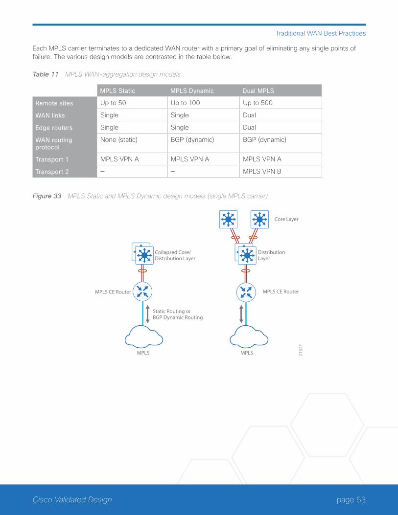
page 53Cisco Validated Design
Traditional WAN Best Practices
Each MPLS carrier terminates to a dedicated WAN router with a primary goal of eliminating any single points of failure. The various design models are contrasted in the table below.
Table 11 MPLS WAN-aggregation design models
MPLS Static MPLS Dynamic Dual MPLS
Remote sites Up to 50 Up to 100 Up to 500
WAN links Single Single Dual
Edge routers Single Single Dual
WAN routing protocol
None (static) BGP (dynamic) BGP (dynamic)
Transport 1 MPLS VPN A MPLS VPN A MPLS VPN A
Transport 2 — — MPLS VPN B
Figure 33 MPLS Static and MPLS Dynamic design models (single MPLS carrier)
2183
F
MPLS
MPLS CE Router MPLS CE Router
Static Routing orBGP Dynamic Routing
Collapsed Core/Distribution Layer
MPLS
Core Layer
DistributionLayer
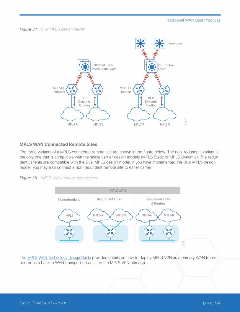
page 54Cisco Validated Design
Traditional WAN Best Practices
Figure 34 Dual MPLS design model
2184
F
MPLS CERouters
BGPDynamicRouting
MPLS A MPLS B
MPLS CERouters
BGPDynamicRouting
MPLS A MPLS B
Collapsed Core/Distribution Layer
DistributionLayer
Core Layer
MPLS WAN Connected Remote Sites
The three variants of a MPLS connected remote site are shown in the figure below. The non-redundant variant is the only one that is compatible with the single carrier design models (MPLS Static or MPLS Dynamic). The redun-dant variants are compatible with the Dual MPLS design model. If you have implemented the Dual MPLS design model, you may also connect a non-redundant remote site to either carrier.
Figure 35 MPLS WAN remote-site designs21
17F
Redundant Links Redundant Links & Routers
Nonredundant
MPLS WAN
MPLS MPLS-A MPLS-B MPLS-A MPLS-B
The MPLS WAN Technology Design Guide provides details on how to deploy MPLS VPN as a primary WAN trans-port or as a backup WAN transport (to an alternate MPLS VPN primary).
page 55Cisco Validated Design
Traditional WAN Best Practices
LAYER 2 WAN USING VPLS OR METRO ETHERNETEthernet has traditionally been a LAN technology primarily due to the distance limitations of the available media and the requirement for dedicated copper or fiber links.
Layer 2 WAN transports are now widely available from service providers and are able to extend various Layer 2 traffic types (Frame Relay, Point-to-Point Protocol (PPP), ATM, or Ethernet) over a WAN. The most common implementations of Layer 2 WAN are used to provide Ethernet over the WAN using either a point-to-point or point-to-multipoint service.
Service providers implement these Ethernet services using a variety of methods. MPLS networks support both EoMPLS and VPLS. The providers use other network technologies, such as Ethernet switches in various topolo-gies, to provide Ethernet Layer 2 WAN services. These offerings are also referred to as Carrier Ethernet or Metro Ethernet, and they are typically limited to a relatively small geographic area.
Layer 2 WAN supports a subscriber model in which the service provider is transparent and the organization im-plements all Layer 3 routing. This allows for flexibility in the WAN design and interconnection of the remote sites.
Point-to-point service allows for the interconnection of two LANs. Point-to-multipoint transparent LAN service allows for the interconnection of more than two LANs. Other service variants include simple and trunked demar-cations. By using trunk mode, you can interconnect LANs using 802.1Q virtual local area network (VLAN) tagging in order to provide transport of multiple VLANs on a single access trunk. Service providers often refer to a trunked service as Q-in-Q tunneling.
Layer 2 WAN transport is transparent to the traffic type; therefore IP multicast traffic is supported with no addi-tional configuration required by the service provider.
The Layer 2 WAN-aggregation (hub) design uses a single WAN edge router. When a WAN edge router is referred to in the context of the connection to a carrier or service provider, it is typically known as a CE router. The WAN edge router connects into a distribution layer.
This design documents two WAN-aggregation design models that use either simple demarcation or trunked de-marcation. The primary difference between the Simple Demarcation and Trunked Demarcation design models is the number of broadcast domains or VLANs that are used to communicate with a subset of remote-site routers.
Each of the design models uses LAN connections into either a collapsed core/distribution layer or a dedicated WAN distribution layer. There are no functional differences between these two methods from the WAN-aggrega-tion perspective.
In the WAN-aggregation design, tasks such as IP route summarization are performed at the distribution layer. There are other various devices supporting WAN edge services, such as application optimization and encryption, and these devices should also connect into the distribution layer.
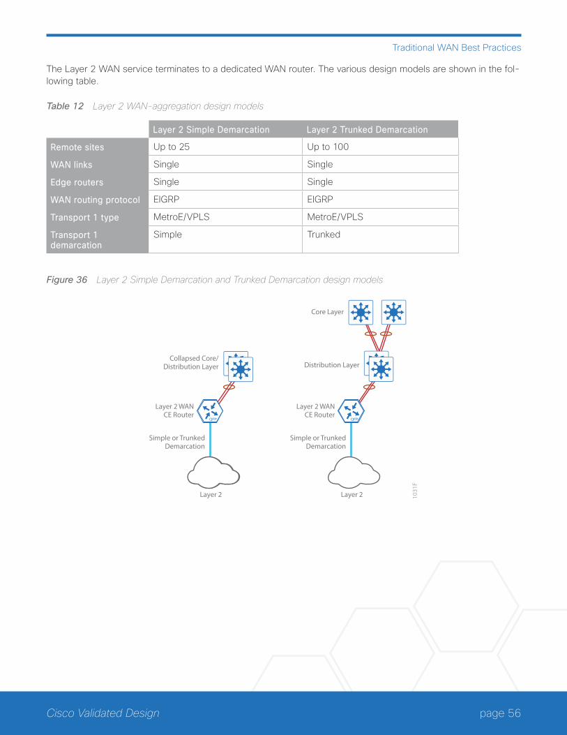
page 56Cisco Validated Design
Traditional WAN Best Practices
The Layer 2 WAN service terminates to a dedicated WAN router. The various design models are shown in the fol-lowing table.
Table 12 Layer 2 WAN-aggregation design models
Layer 2 Simple Demarcation Layer 2 Trunked Demarcation
Remote sites Up to 25 Up to 100
WAN links Single Single
Edge routers Single Single
WAN routing protocol EIGRP EIGRP
Transport 1 type MetroE/VPLS MetroE/VPLS
Transport 1 demarcation
Simple Trunked
Figure 36 Layer 2 Simple Demarcation and Trunked Demarcation design models
1031
F
Layer 2
Layer 2 WANCE Router
Simple or TrunkedDemarcation
Collapsed Core/Distribution Layer
Layer 2
Layer 2 WANCE Router
Simple or TrunkedDemarcation
Distribution Layer
Core Layer
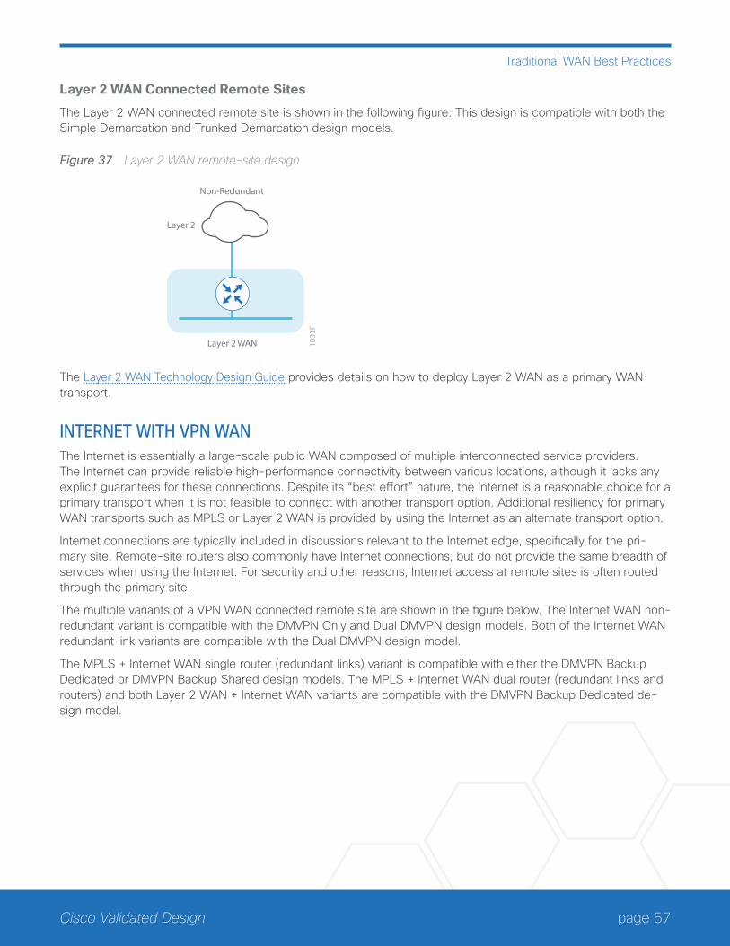
page 57Cisco Validated Design
Traditional WAN Best Practices
Layer 2 WAN Connected Remote Sites
The Layer 2 WAN connected remote site is shown in the following figure. This design is compatible with both the Simple Demarcation and Trunked Demarcation design models.
Figure 37 Layer 2 WAN remote-site design
1033
F
Non-Redundant
Layer 2
Layer 2 WAN
The Layer 2 WAN Technology Design Guide provides details on how to deploy Layer 2 WAN as a primary WAN transport.
INTERNET WITH VPN WANThe Internet is essentially a large-scale public WAN composed of multiple interconnected service providers. The Internet can provide reliable high-performance connectivity between various locations, although it lacks any explicit guarantees for these connections. Despite its “best effort” nature, the Internet is a reasonable choice for a primary transport when it is not feasible to connect with another transport option. Additional resiliency for primary WAN transports such as MPLS or Layer 2 WAN is provided by using the Internet as an alternate transport option.
Internet connections are typically included in discussions relevant to the Internet edge, specifically for the pri-mary site. Remote-site routers also commonly have Internet connections, but do not provide the same breadth of services when using the Internet. For security and other reasons, Internet access at remote sites is often routed through the primary site.
The multiple variants of a VPN WAN connected remote site are shown in the figure below. The Internet WAN non-redundant variant is compatible with the DMVPN Only and Dual DMVPN design models. Both of the Internet WAN redundant link variants are compatible with the Dual DMVPN design model.
The MPLS + Internet WAN single router (redundant links) variant is compatible with either the DMVPN Backup Dedicated or DMVPN Backup Shared design models. The MPLS + Internet WAN dual router (redundant links and routers) and both Layer 2 WAN + Internet WAN variants are compatible with the DMVPN Backup Dedicated de-sign model.
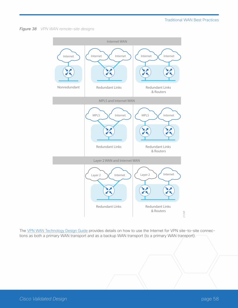
page 58Cisco Validated Design
Traditional WAN Best Practices
Figure 38 VPN WAN remote-site designs
2139
F
Redundant Links Redundant Links & Routers
Nonredundant
Internet Internet Internet Internet Internet
Internet WAN
Redundant Links Redundant Links & Routers
MPLS Internet MPLS Internet
MPLS and Internet WAN
Redundant Links Redundant Links & Routers
Internet Internet
Layer 2 WAN and Internet WAN
Layer 2 Layer 2
The VPN WAN Technology Design Guide provides details on how to use the Internet for VPN site-to-site connec-tions as both a primary WAN transport and as a backup WAN transport (to a primary WAN transport).
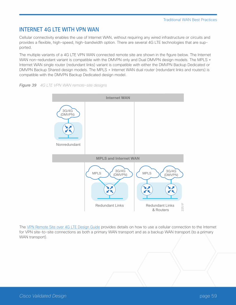
page 59Cisco Validated Design
Traditional WAN Best Practices
INTERNET 4G LTE WITH VPN WANCellular connectivity enables the use of Internet WAN, without requiring any wired infrastructure or circuits and provides a flexible, high-speed, high-bandwidth option. There are several 4G LTE technologies that are sup-ported.
The multiple variants of a 4G LTE VPN WAN connected remote site are shown in the figure below. The Internet WAN non-redundant variant is compatible with the DMVPN only and Dual DMVPN design models. The MPLS + Internet WAN single router (redundant links) variant is compatible with either the DMVPN Backup Dedicated or DMVPN Backup Shared design models. The MPLS + Internet WAN dual router (redundant links and routers) is compatible with the DMVPN Backup Dedicated design model.
Figure 39 4G LTE VPN WAN remote-site designs
22
51
F
Nonredundant
3G/4G(DMVPN)
Internet WAN
Redundant Links Redundant Links & Routers
MPLS MPLS
MPLS and Internet WAN
3G/4G(DMVPN)
3G/4G(DMVPN)
The VPN Remote Site over 4G LTE Design Guide provides details on how to use a cellular connection to the Internet for VPN site-to-site connections as both a primary WAN transport and as a backup WAN transport (to a primary WAN transport).
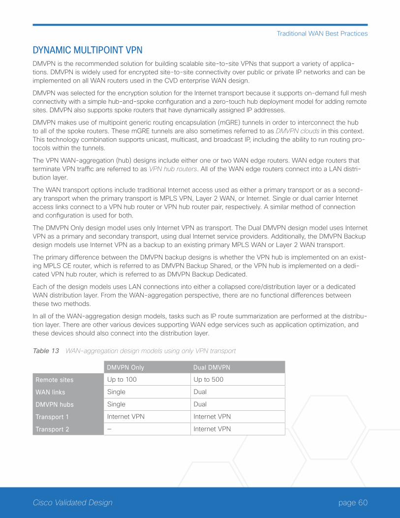
page 60Cisco Validated Design
Traditional WAN Best Practices
DYNAMIC MULTIPOINT VPNDMVPN is the recommended solution for building scalable site-to-site VPNs that support a variety of applica-tions. DMVPN is widely used for encrypted site-to-site connectivity over public or private IP networks and can be implemented on all WAN routers used in the CVD enterprise WAN design.
DMVPN was selected for the encryption solution for the Internet transport because it supports on-demand full mesh connectivity with a simple hub-and-spoke configuration and a zero-touch hub deployment model for adding remote sites. DMVPN also supports spoke routers that have dynamically assigned IP addresses.
DMVPN makes use of multipoint generic routing encapsulation (mGRE) tunnels in order to interconnect the hub to all of the spoke routers. These mGRE tunnels are also sometimes referred to as DMVPN clouds in this context. This technology combination supports unicast, multicast, and broadcast IP, including the ability to run routing pro-tocols within the tunnels.
The VPN WAN-aggregation (hub) designs include either one or two WAN edge routers. WAN edge routers that terminate VPN traffic are referred to as VPN hub routers. All of the WAN edge routers connect into a LAN distri-bution layer.
The WAN transport options include traditional Internet access used as either a primary transport or as a second-ary transport when the primary transport is MPLS VPN, Layer 2 WAN, or Internet. Single or dual carrier Internet access links connect to a VPN hub router or VPN hub router pair, respectively. A similar method of connection and configuration is used for both.
The DMVPN Only design model uses only Internet VPN as transport. The Dual DMVPN design model uses Internet VPN as a primary and secondary transport, using dual Internet service providers. Additionally, the DMVPN Backup design models use Internet VPN as a backup to an existing primary MPLS WAN or Layer 2 WAN transport.
The primary difference between the DMVPN backup designs is whether the VPN hub is implemented on an exist-ing MPLS CE router, which is referred to as DMVPN Backup Shared, or the VPN hub is implemented on a dedi-cated VPN hub router, which is referred to as DMVPN Backup Dedicated.
Each of the design models uses LAN connections into either a collapsed core/distribution layer or a dedicated WAN distribution layer. From the WAN-aggregation perspective, there are no functional differences between these two methods.
In all of the WAN-aggregation design models, tasks such as IP route summarization are performed at the distribu-tion layer. There are other various devices supporting WAN edge services such as application optimization, and these devices should also connect into the distribution layer.
Table 13 WAN-aggregation design models using only VPN transport
DMVPN Only Dual DMVPN
Remote sites Up to 100 Up to 500
WAN links Single Dual
DMVPN hubs Single Dual
Transport 1 Internet VPN Internet VPN
Transport 2 — Internet VPN
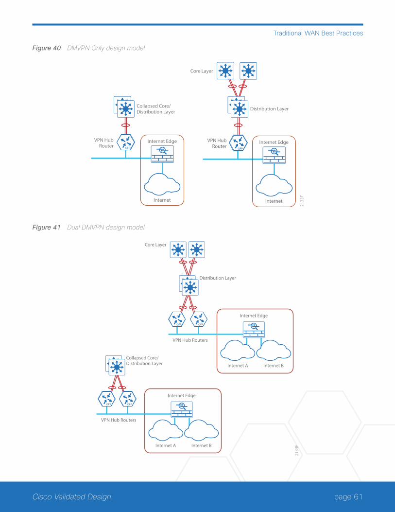
page 61Cisco Validated Design
Traditional WAN Best Practices
Figure 40 DMVPN Only design model
2133
F
VPN HubRouter
Core Layer
Internet
Internet Edge
Collapsed Core/Distribution Layer
VPN HubRouter
Internet
Internet Edge
Distribution Layer
Figure 41 Dual DMVPN design model
2134
F
Core Layer
Collapsed Core/Distribution Layer
Internet Edge
Internet A Internet B
Distribution Layer
Internet Edge
Internet A Internet B
VPN Hub Routers
VPN Hub Routers
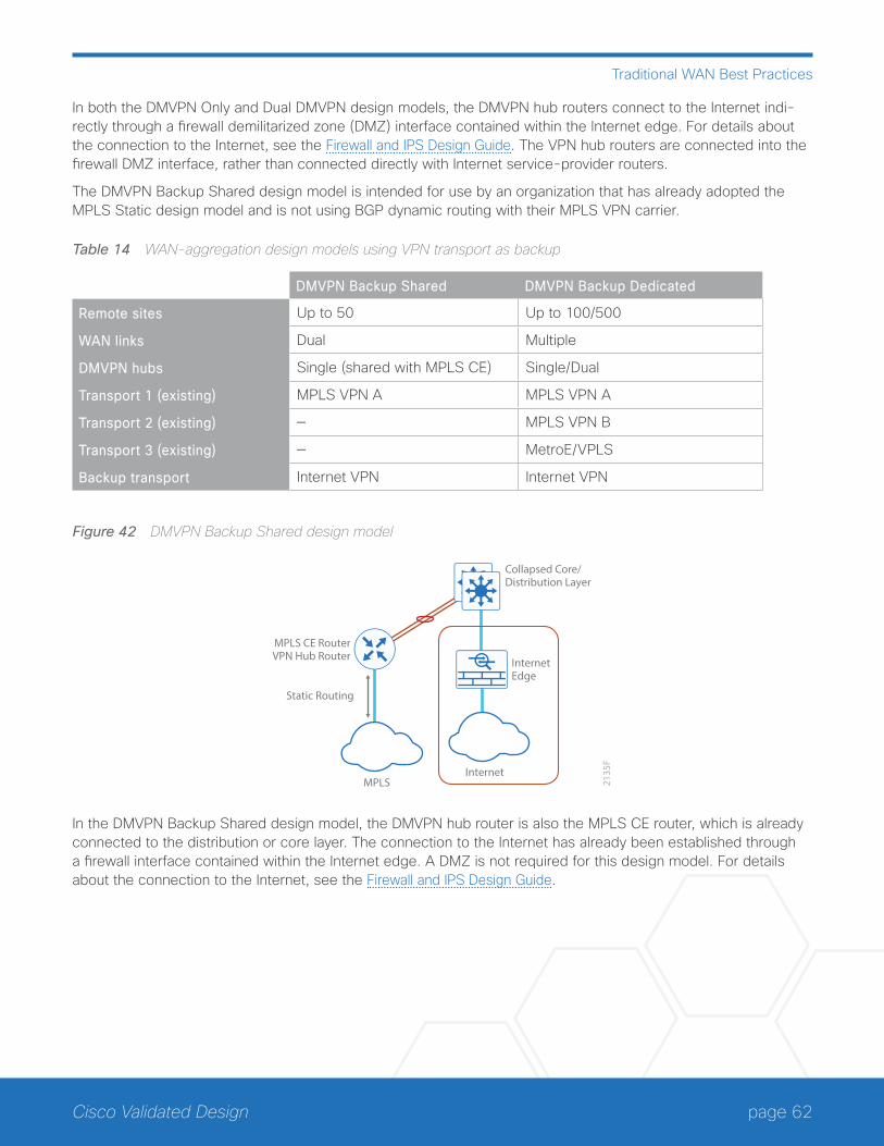
page 62Cisco Validated Design
Traditional WAN Best Practices
In both the DMVPN Only and Dual DMVPN design models, the DMVPN hub routers connect to the Internet indi-rectly through a firewall demilitarized zone (DMZ) interface contained within the Internet edge. For details about the connection to the Internet, see the Firewall and IPS Design Guide. The VPN hub routers are connected into the firewall DMZ interface, rather than connected directly with Internet service-provider routers.
The DMVPN Backup Shared design model is intended for use by an organization that has already adopted the MPLS Static design model and is not using BGP dynamic routing with their MPLS VPN carrier.
Table 14 WAN-aggregation design models using VPN transport as backup
DMVPN Backup Shared DMVPN Backup Dedicated
Remote sites Up to 50 Up to 100/500
WAN links Dual Multiple
DMVPN hubs Single (shared with MPLS CE) Single/Dual
Transport 1 (existing) MPLS VPN A MPLS VPN A
Transport 2 (existing) — MPLS VPN B
Transport 3 (existing) — MetroE/VPLS
Backup transport Internet VPN Internet VPN
Figure 42 DMVPN Backup Shared design model
2135
F
Internet
InternetEdge
MPLS
MPLS CE RouterVPN Hub Router
Collapsed Core/Distribution Layer
Static Routing
In the DMVPN Backup Shared design model, the DMVPN hub router is also the MPLS CE router, which is already connected to the distribution or core layer. The connection to the Internet has already been established through a firewall interface contained within the Internet edge. A DMZ is not required for this design model. For details about the connection to the Internet, see the Firewall and IPS Design Guide.
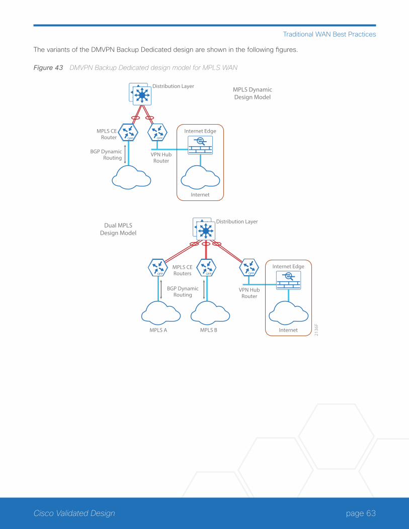
page 63Cisco Validated Design
Traditional WAN Best Practices
The variants of the DMVPN Backup Dedicated design are shown in the following figures.
Figure 43 DMVPN Backup Dedicated design model for MPLS WAN
2136
F
MPLS CERouters
VPN HubRouter
Internet
Internet Edge
Distribution Layer
MPLS BMPLS A
MPLS CERouter
VPN HubRouter
Internet
Internet Edge
Distribution Layer
BGP DynamicRouting
BGP DynamicRouting
MPLS DynamicDesign Model
Dual MPLSDesign Model
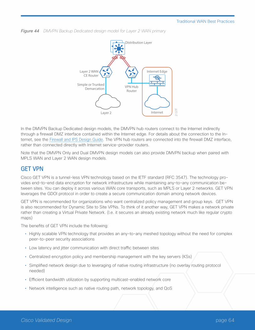
page 64Cisco Validated Design
Traditional WAN Best Practices
Figure 44 DMVPN Backup Dedicated design model for Layer 2 WAN primary
VPN HubRouter
2137
F
Layer 2 WANCE Router
Layer 2 Internet
Internet Edge
Distribution Layer
Simple or TrunkedDemarcation
In the DMVPN Backup Dedicated design models, the DMVPN hub routers connect to the Internet indirectly through a firewall DMZ interface contained within the Internet edge. For details about the connection to the In-ternet, see the Firewall and IPS Design Guide. The VPN hub routers are connected into the firewall DMZ interface, rather than connected directly with Internet service-provider routers.
Note that the DMVPN Only and Dual DMVPN design models can also provide DMVPN backup when paired with MPLS WAN and Layer 2 WAN design models.
GET VPNCisco GET VPN is a tunnel-less VPN technology based on the IETF standard (RFC 3547). The technology pro-vides end-to-end data encryption for network infrastructure while maintaining any-to-any communication be-tween sites. You can deploy it across various WAN core transports, such as MPLS or Layer 2 networks. GET VPN leverages the GDOI protocol in order to create a secure communication domain among network devices.
GET VPN is recommended for organizations who want centralized policy management and group keys. GET VPN is also recommended for Dynamic Site to Site VPNs. To think of it another way, GET VPN makes a network private rather than creating a Virtual Private Network. (I.e. it secures an already existing network much like regular crypto maps)
The benefits of GET VPN include the following:
• Highly scalable VPN technology that provides an any-to-any meshed topology without the need for complex peer-to-peer security associations
• Low latency and jitter communication with direct traffic between sites
• Centralized encryption policy and membership management with the key servers (KSs)
• Simplified network design due to leveraging of native routing infrastructure (no overlay routing protocol needed)
• Efficient bandwidth utilization by supporting multicast-enabled network core
• Network intelligence such as native routing path, network topology, and QoS
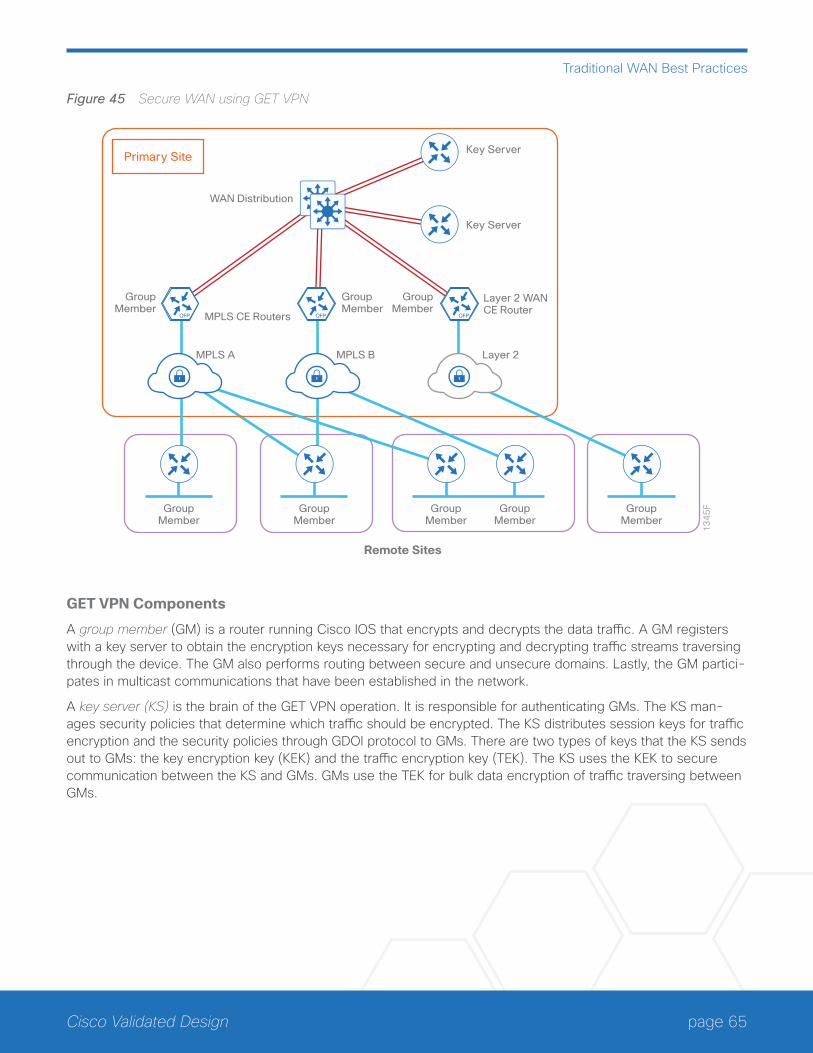
page 65Cisco Validated Design
Traditional WAN Best Practices
Figure 45 Secure WAN using GET VPN
GroupMember
GroupMember
GroupMember
GroupMember
GroupMember
Primary Site
13
45
F
MPLS CE Routers
MPLS A MPLS B Layer 2
WAN Distribution
Layer 2 WANCE Router
Key Server
Key Server
Remote Sites
GroupMember
GroupMember
GroupMember
GET VPN Components
A group member (GM) is a router running Cisco IOS that encrypts and decrypts the data traffic. A GM registers with a key server to obtain the encryption keys necessary for encrypting and decrypting traffic streams traversing through the device. The GM also performs routing between secure and unsecure domains. Lastly, the GM partici-pates in multicast communications that have been established in the network.
A key server (KS) is the brain of the GET VPN operation. It is responsible for authenticating GMs. The KS man-ages security policies that determine which traffic should be encrypted. The KS distributes session keys for traffic encryption and the security policies through GDOI protocol to GMs. There are two types of keys that the KS sends out to GMs: the key encryption key (KEK) and the traffic encryption key (TEK). The KS uses the KEK to secure communication between the KS and GMs. GMs use the TEK for bulk data encryption of traffic traversing between GMs.
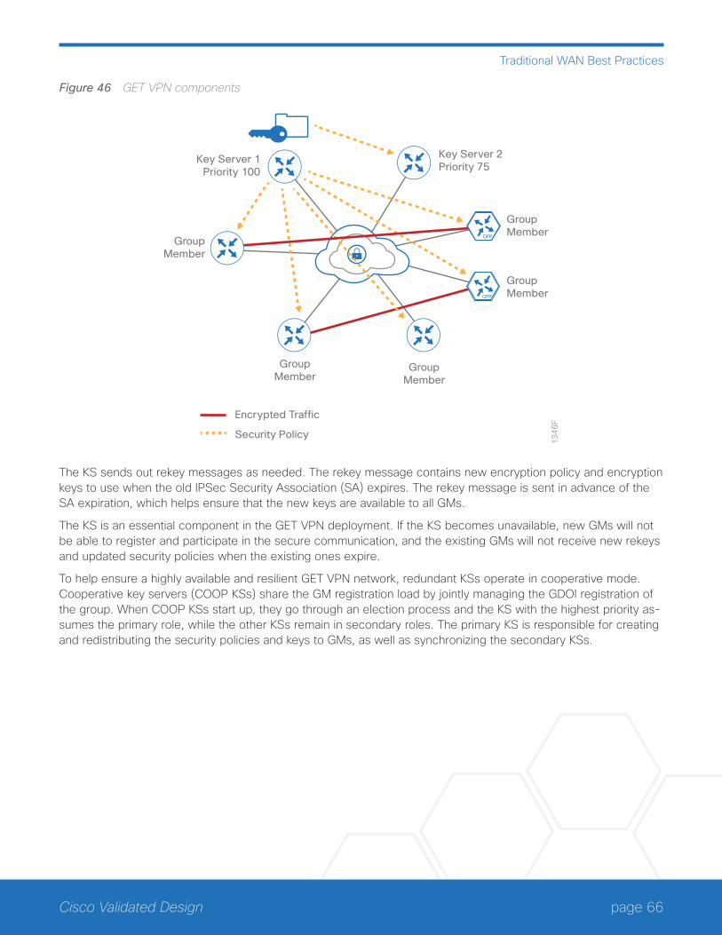
page 66Cisco Validated Design
Traditional WAN Best Practices
Figure 46 GET VPN components
Key Server 1Priority 100
13
46
F
GroupMember
Key Server 2Priority 75
GroupMember
GroupMember
GroupMember
GroupMember
Encrypted Traffic
Security Policy
The KS sends out rekey messages as needed. The rekey message contains new encryption policy and encryption keys to use when the old IPSec Security Association (SA) expires. The rekey message is sent in advance of the SA expiration, which helps ensure that the new keys are available to all GMs.
The KS is an essential component in the GET VPN deployment. If the KS becomes unavailable, new GMs will not be able to register and participate in the secure communication, and the existing GMs will not receive new rekeys and updated security policies when the existing ones expire.
To help ensure a highly available and resilient GET VPN network, redundant KSs operate in cooperative mode. Cooperative key servers (COOP KSs) share the GM registration load by jointly managing the GDOI registration of the group. When COOP KSs start up, they go through an election process and the KS with the highest priority as-sumes the primary role, while the other KSs remain in secondary roles. The primary KS is responsible for creating and redistributing the security policies and keys to GMs, as well as synchronizing the secondary KSs.
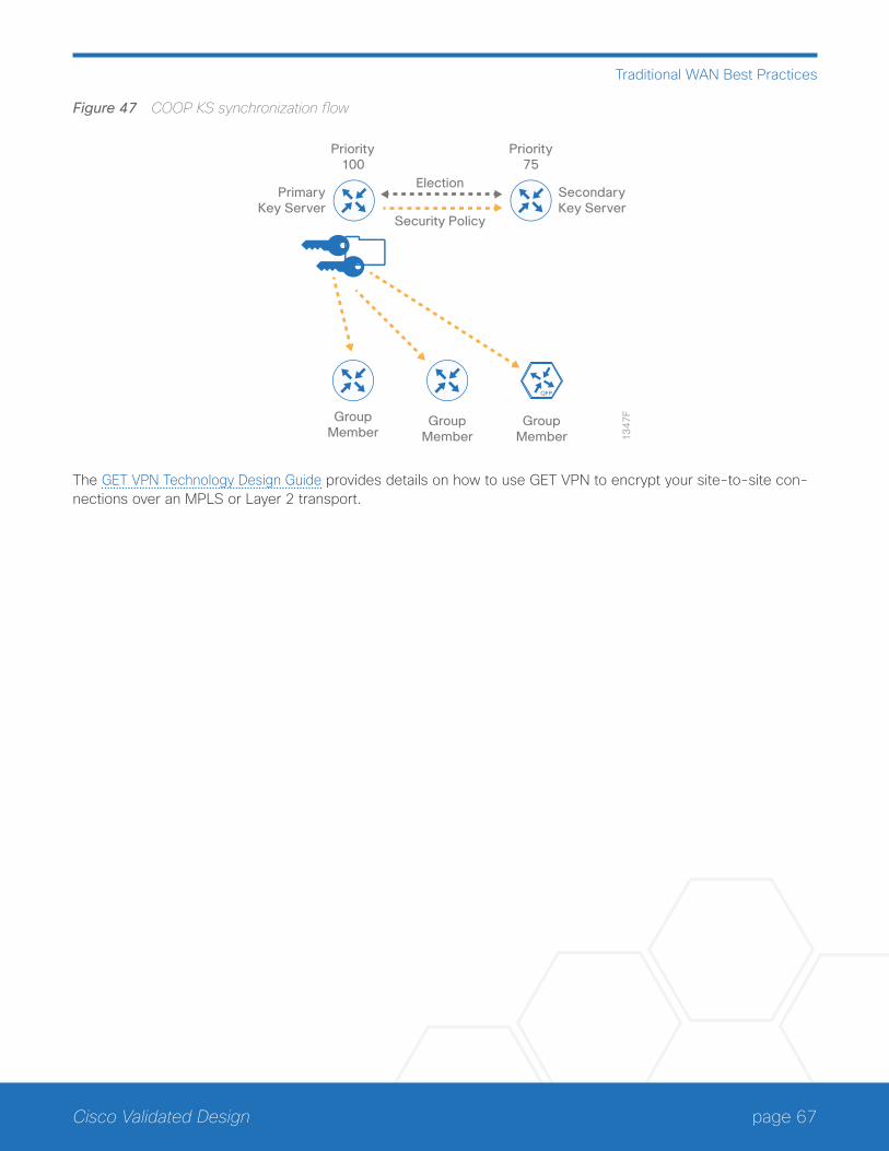
page 67Cisco Validated Design
Traditional WAN Best Practices
Figure 47 COOP KS synchronization flow
PrimaryKey Server
13
47
F
SecondaryKey Server
Priority100
GroupMember
GroupMember
GroupMember
Priority75
Security Policy
Election
The GET VPN Technology Design Guide provides details on how to use GET VPN to encrypt your site-to-site con-nections over an MPLS or Layer 2 transport.
page 68Cisco Validated Design
Summary for Traditional WAN
Summary for Traditional WANCisco Enterprise WAN architectures are proven solutions that scale to all remote-site sizes over any transport. With rich application and security services on a single platform, IT can scale to hundreds of sites. Also, customers can maintain granular control, from the remote site, to the data center, and out to the public cloud. The traffic is dynamically routed based on application, endpoint, and network conditions to help ensure the best user experi-ence. IT can confidently roll out critical business services such as consolidated data centers, SaaS, IP telephony, and video without overwhelming the WAN.

Americas HeadquartersCisco Systems, Inc.San Jose, CA
Asia Pacific HeadquartersCisco Systems (USA) Pte. Ltd.Singapore
Europe HeadquartersCisco Systems International BV Amsterdam,The Netherlands
Cisco has more than 200 offices worldwide. Addresses, phone numbers, and fax numbers are listed on the Cisco Website at www.cisco.com/go/offices.
ALL DESIGNS, SPECIFICATIONS, STATEMENTS, INFORMATION, AND RECOMMENDATIONS (COLLECTIVELY, “DESIGNS”) IN THIS MANUAL ARE PRESENTED “AS IS,” WITH ALL FAULTS. CISCO AND ITS SUPPLIERS DISCLAIM ALL WARRANTIES, INCLUDING, WITHOUT LIMITATION, THE WARRANTY OF MERCHANTABILITY, FITNESS FOR A PARTICULAR PURPOSE AND NONINFRINGEMENT OR ARISING FROM A COURSE OF DEALING, USAGE, OR TRADE PRACTICE. IN NO EVENT SHALL CISCO OR ITS SUPPLIERS BE LIABLE FOR ANY INDIRECT, SPECIAL, CONSEQUENTIAL, OR INCIDENTAL DAMAGES, INCLUDING, WITHOUT LIMITATION, LOST PROFITS OR LOSS OR DAMAGE TO DATA ARISING OUT OF THE USE OR INABILITY TO USE THE DESIGNS, EVEN IF CISCO OR ITS SUPPLIERS HAVE BEEN ADVISED OF THE POSSIBILITY OF SUCH DAMAGES. THE DESIGNS ARE SUBJECT TO CHANGE WITHOUT NOTICE. USERS ARE SOLELY RESPONSIBLE FOR THEIR APPLICATION OF THE DESIGNS. THE DESIGNS DO NOT CONSTITUTE THE TECHNICAL OR OTHER PROFESSIONAL ADVICE OF CISCO, ITS SUPPLIERS OR PARTNERS. USERS SHOULD CONSULT THEIR OWN TECHNICAL ADVISORS BEFORE IMPLEMENTING THE DESIGNS. RESULTS MAY VARY DEPENDING ON FACTORS NOT TESTED BY CISCO.
Any Internet Protocol (IP) addresses used in this document are not intended to be actual addresses. Any examples, command display output, and figures included in the document are shown for illustrative purposes only. Any use of actual IP addresses in illustrative content is unintentional and coincidental.
© 2015 Cisco Systems, Inc. All rights reserved.
Cisco and the Cisco logo are trademarks or registered trademarks of Cisco and/or its affiliates in the U.S. and other countries. To view a list of Cisco trademarks, go to this URL: www.cisco.com/go/trademarks. Third-party trademarks mentioned are the property of their respective owners. The use of the word partner does not imply a partnership relationship between Cisco and any other company. (1110R)
Cisco Validated Design
Please use the feedback form to send comments and suggestions about this guide.
B-000300c-2 10/15