Embed Size (px)
Citation preview
687
Reflection andRefraction of Light
CHAPTER OUTLINE 25.1 The Nature of Light 25.2 The Ray Model in
Geometric Optics 25.3 The Wave Under
Reflection 25.4 The Wave Under
Refraction 25.5 Dispersion and Prisms 25.6 Huygens’s Principle 25.7 Total Internal Reflection 25.8 Context
ConnectionOptical Fibers
ANSWERS TO QUESTIONS Q25.1 The ray approximation, predicting sharp shadows, is valid for λ << d .
For λ ~ d diffraction effects become important, and the light waves will spread out noticeably beyond the slit.
Q25.2 With a vertical shop window, streetlights and his own
reflection can impede the window shopper’s clear view of the display. The tilted shop window can put these reflections out of the way. Windows of airport control towers are also tilted like this, as are automobile windshields.
FIG. Q25.2 Q25.3 The right-hand fish image is light from the right side of the actual fish, refracted toward the
observer, and the second image is light from the left side of the fish refracted toward the observer. Q25.4 An echo is an example of the reflection of sound. Hearing the noise of a distant highway on a cold
morning, when you cannot hear it after the ground warms up, is an example of acoustical refraction. You can use a rubber inner tube inflated with helium as an acoustical lens to concentrate sound in the way a lens can focus light. At your next party, see if you can experimentally find the approximate focal point!
Q25.5 Suppose the light moves into a medium of higher refractive index. Then its wavelength decreases.
The frequency remains constant. The speed diminishes by a factor equal to the index of refraction.
688 Reflection and Refraction of Light
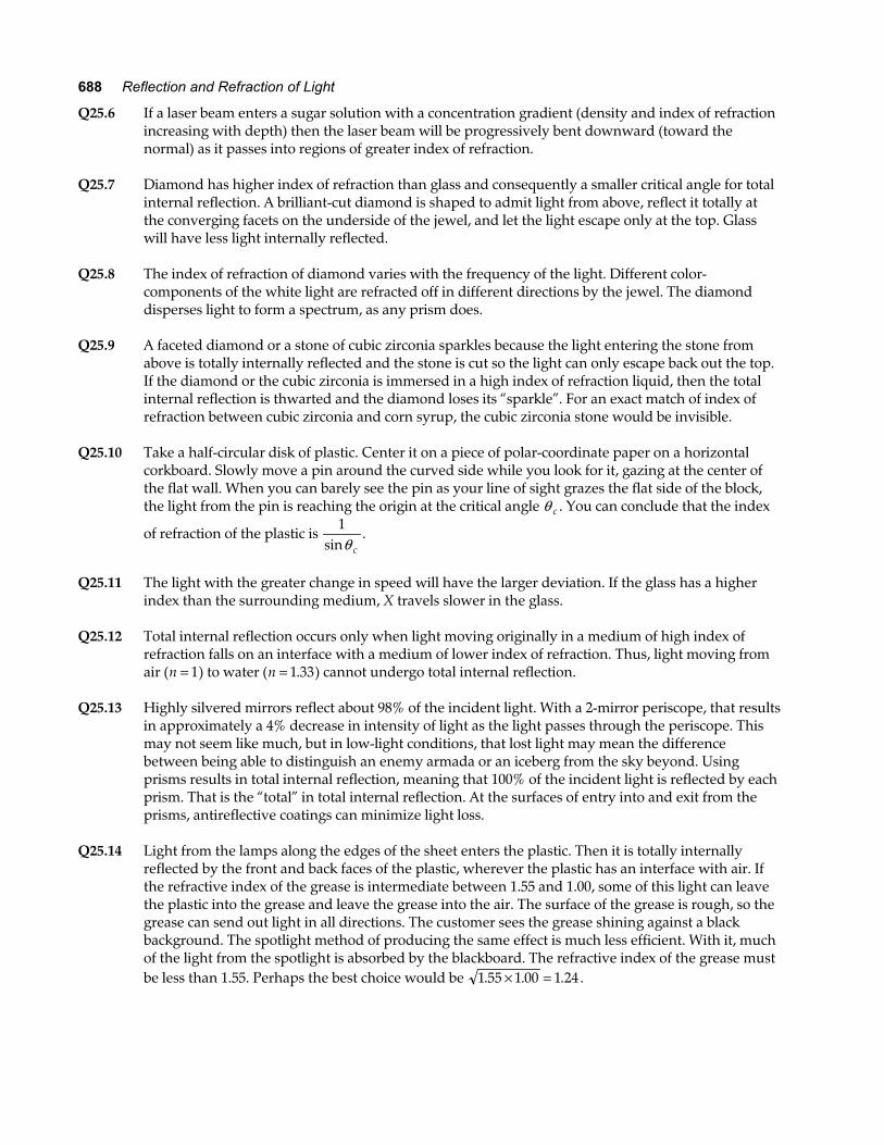
Q25.6 If a laser beam enters a sugar solution with a concentration gradient (density and index of refraction increasing with depth) then the laser beam will be progressively bent downward (toward the normal) as it passes into regions of greater index of refraction.
Q25.7 Diamond has higher index of refraction than glass and consequently a smaller critical angle for total
internal reflection. A brilliant-cut diamond is shaped to admit light from above, reflect it totally at the converging facets on the underside of the jewel, and let the light escape only at the top. Glass will have less light internally reflected.
Q25.8 The index of refraction of diamond varies with the frequency of the light. Different color-
components of the white light are refracted off in different directions by the jewel. The diamond disperses light to form a spectrum, as any prism does.
Q25.9 A faceted diamond or a stone of cubic zirconia sparkles because the light entering the stone from
above is totally internally reflected and the stone is cut so the light can only escape back out the top. If the diamond or the cubic zirconia is immersed in a high index of refraction liquid, then the total internal reflection is thwarted and the diamond loses its “sparkle”. For an exact match of index of refraction between cubic zirconia and corn syrup, the cubic zirconia stone would be invisible.
Q25.10 Take a half-circular disk of plastic. Center it on a piece of polar-coordinate paper on a horizontal
corkboard. Slowly move a pin around the curved side while you look for it, gazing at the center of the flat wall. When you can barely see the pin as your line of sight grazes the flat side of the block, the light from the pin is reaching the origin at the critical angle θ c . You can conclude that the index
of refraction of the plastic is 1
sinθ c.
Q25.11 The light with the greater change in speed will have the larger deviation. If the glass has a higher
index than the surrounding medium, X travels slower in the glass. Q25.12 Total internal reflection occurs only when light moving originally in a medium of high index of
refraction falls on an interface with a medium of lower index of refraction. Thus, light moving from air (n = 1) to water (n = 1 33. ) cannot undergo total internal reflection.
Q25.13 Highly silvered mirrors reflect about 98% of the incident light. With a 2-mirror periscope, that results
in approximately a 4% decrease in intensity of light as the light passes through the periscope. This may not seem like much, but in low-light conditions, that lost light may mean the difference between being able to distinguish an enemy armada or an iceberg from the sky beyond. Using prisms results in total internal reflection, meaning that 100% of the incident light is reflected by each prism. That is the “total” in total internal reflection. At the surfaces of entry into and exit from the prisms, antireflective coatings can minimize light loss.
Q25.14 Light from the lamps along the edges of the sheet enters the plastic. Then it is totally internally
reflected by the front and back faces of the plastic, wherever the plastic has an interface with air. If the refractive index of the grease is intermediate between 1.55 and 1.00, some of this light can leave the plastic into the grease and leave the grease into the air. The surface of the grease is rough, so the grease can send out light in all directions. The customer sees the grease shining against a black background. The spotlight method of producing the same effect is much less efficient. With it, much of the light from the spotlight is absorbed by the blackboard. The refractive index of the grease must be less than 1.55. Perhaps the best choice would be 1 55 1 00 1 24. . .× = .
Chapter 25 689
Q25.15 At the altitude of the plane the surface of the Earth need not block off the lower half of the rainbow. Thus, the full circle can be seen. You can see such a rainbow by climbing on a stepladder above a garden sprinkler in the middle of a sunny day. Set the sprinkler for fine mist. Do not let the slippery children fall from the ladder.
Q25.16 A mirage occurs when light changes direction as it moves between batches of air having different
indices of refraction because they have different densities at different temperatures. When the sun makes a blacktop road hot, an apparent wet spot is bright due to refraction of light from the bright sky. The light, originally headed a little below the horizontal, always bends up as it first enters and then leaves sequentially hotter, lower-density, lower-index layers of air closer to the road surface.
SOLUTIONS TO PROBLEMS Section 25.1 The Nature of Light No problems in this section
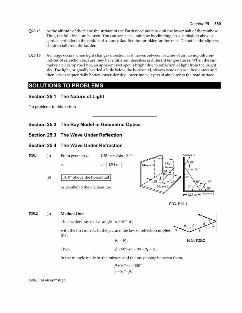
Section 25.2 The Ray Model in Geometric Optics Section 25.3 The Wave Under Reflection Section 25.4 The Wave Under Refraction P25.1 (a) From geometry, 1 25 40 0. sin .m = °d
so d = 1 94. m .
(b) 50 0. ° above the horizontal
or parallel to the incident ray.
Mirror 2
50°
40°
50°50°
40°d
i1= 40°
i2= 50°
Mirror 11.25 m
40.0°
1.25 mMirror 1
Mirror 2 Lightbeam
P
FIG. P25.1
P25.2 (a) Method One:
The incident ray makes angle α θ= °−90 1
with the first mirror. In the picture, the law of reflection implies that
θ θ1 1= ′ .
Then β θ θ α= °− ′ = − =90 901 1 .
FIG. P25.2
In the triangle made by the mirrors and the ray passing between them,
β γγ β
+ °+ = °= °−
90 18090 .
continued on next page
690 Reflection and Refraction of Light
Further, δ γ β α= °− = =90
and ∈= =δ α .
Thus the final ray makes the same angle with the first mirror as did the incident ray. Its direction is opposite to the incident ray.
Method Two:
The vector velocity of the incident light has a component vy perpendicular to the first mirror
and a component vx perpendicular to the second. The vy component is reversed upon the
first reflection, which leaves vx unchanged. The second reflection reverses vx and leaves vy
unchanged. The doubly reflected ray then has velocity opposite to the incident ray.
(b) The incident ray has velocity v v vx y z$ $ $i j k+ + . Each reflection reverses one component and
leaves the other two unchanged. After all the reflections, the light has velocity
− − −v v vx y z$ $ $i j k , opposite to the incident ray.
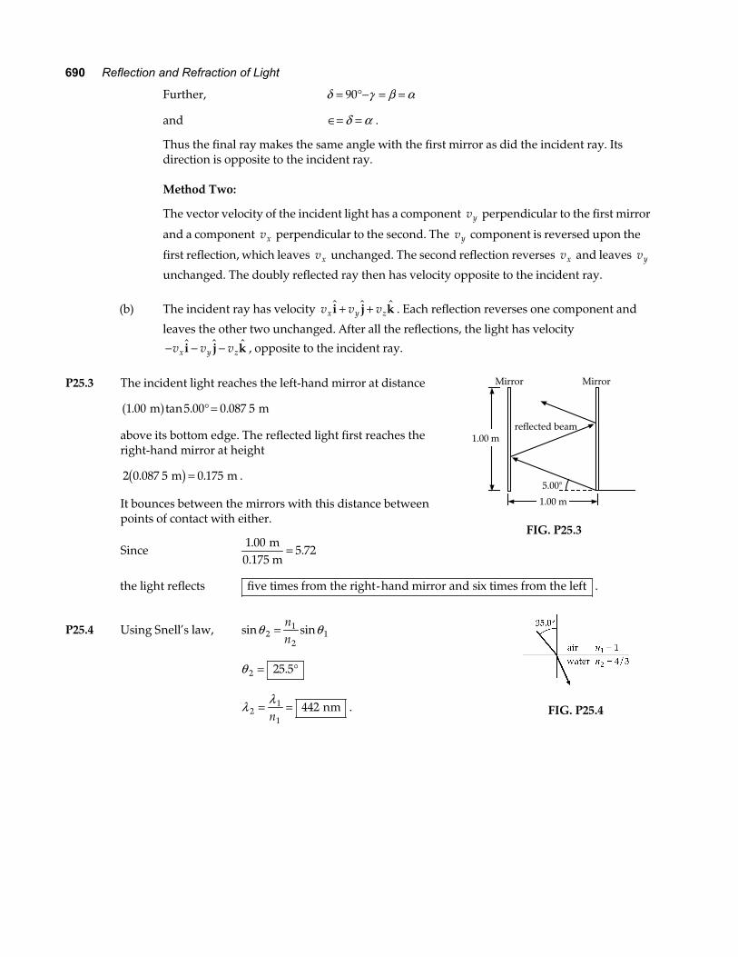
P25.3 The incident light reaches the left-hand mirror at distance
1 00 5 00 0 087 5. tan . . m ma f ° =
above its bottom edge. The reflected light first reaches the right-hand mirror at height
2 0 087 5 0 175. . m mb g = .
It bounces between the mirrors with this distance between points of contact with either.
Since 1 00
5 72.
. m
0.175 m=
Mirror Mirror
reflected beam1.00 m
5.00°
1.00 m
FIG. P25.3
the light reflects five times from the right-hand mirror and six times from the left .
P25.4 Using Snell’s law, sin sinθ θ21
21=
nn
θ 2 25 5= °.
λ λ2
1
1442= =
n nm .
FIG. P25.4
Chapter 25 691
*P25.5 The law of refraction n n1 1 2 2sin sinθ θ= can be put into the more general form
cv
cv
v v
11
22
1
1
2
2
sin sin
sin sin
θ θ
θ θ
=
=
In this form it applies to all kinds of waves that move through space.
sin . sin
sin .
.
3 5343 1 493
0 266
15 4
2
2
2
° =
=
= °
m s m sθ
θ
θ
The wave keeps constant frequency in
fv v
vv
= =
= = =
1
1
2
2
22 1
1
1 493 0 589343
2 56
λ λ
λ λ m s m m s
m.
.a f
P25.6 (a) fc= =
××
= ×−λ3 00 106 328 10
4 74 108
714.
..
m s m
Hz
(b) λ λglass
air nm1.50
nm= = =n
632 8422
.
(c) vcnglassair m s
m s Mm s= =×
= × =3 00 10
1 502 00 10 200
88.
..
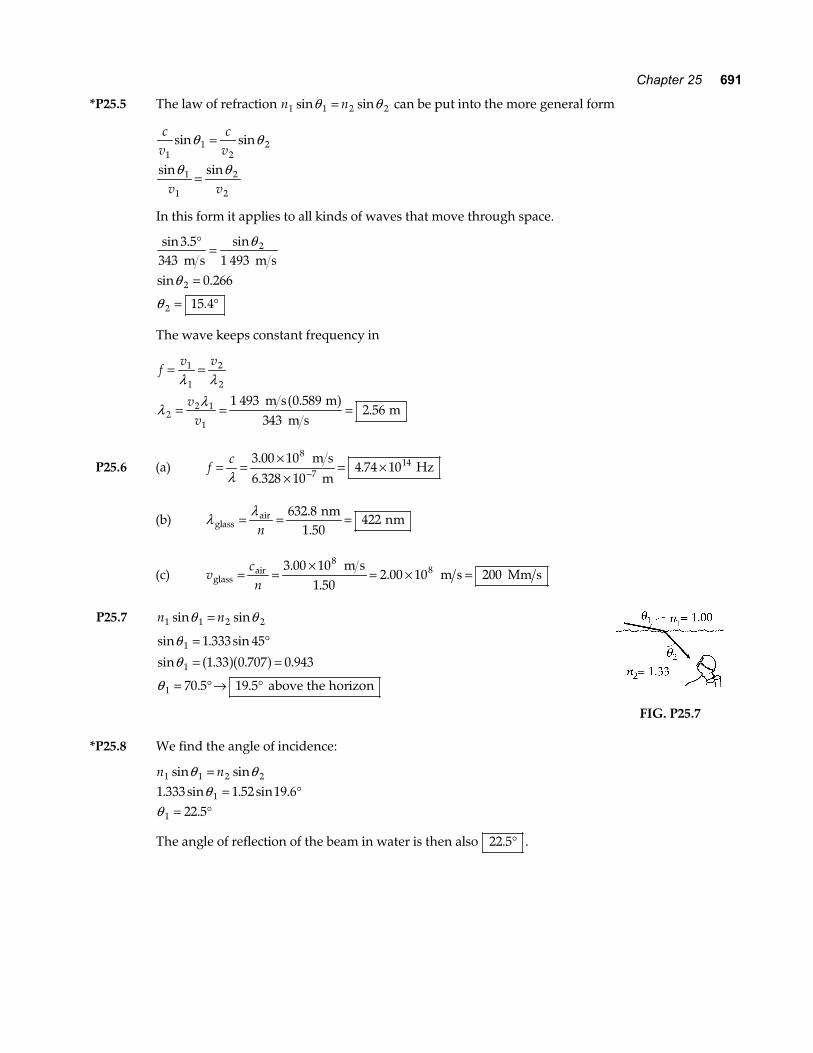
P25.7 n n1 1 2 2sin sinθ θ=
sin . sin
sin . . .
. .
θθ
θ
1
1
1
1 333 45
1 33 0 707 0 943
70 5 19 5
= °= =
= °→ °
a fa f above the horizon
FIG. P25.7
*P25.8 We find the angle of incidence:
n n1 1 2 2
1
1
1 333 1 52 19 622 5
sin sin. sin . sin .
.
θ θθ
θ
== °
= °
The angle of reflection of the beam in water is then also 22 5. ° .
692 Reflection and Refraction of Light
*P25.9 (a) As measured from the diagram, the incidence angle is 60°, and the refraction angle is 35°.
From Snell’s law, sinsin
θθ
2
1
2
1=
vv
, then sinsin
3560
2°°
=vc
and the speed of light in the block is
2 0 108. × m s .
(b) The frequency of the light does not change upon refraction. Knowing the wavelength in a
vacuum, we can use the speed of light in a vacuum to determine the frequency: c f= λ , thus
3 00 10 632 8 108 9. .× = × −f e j , so the frequency is 474 1. THz .
(c) To find the wavelength of light in the block, we use the same wave speed relation, v f= λ , so
2 0 10 4 741 108 14. .× = ×e jλ , so λ glass nm= 420 .
P25.10 (a) n n1 1 2 2sin sinθ θ=
1 00 30 0 19 24
1 52
. sin . sin .
.
° = °
=
n
n
(c) fc= =
××
= ×−λ3 00 106 328 10
4 74 108
714.
..
m s m
Hz in air and in syrup.
(d) vcn
= =×
= × =3 00 10
1 521 98 10 198
88.
..
m s m s Mm s
(b) λ = =×
×=v
f1 98 10
4 74 10417
8
14.
. m s
s nm
P25.11 (a) Flint Glass: vcn
= =×
= × =3 00 10
1 661 81 10 181
88.
..
m s m s Mm s
(b) Water: vcn
= =×
= × =3 00 10
1 3332 25 10 225
88.
..
m s m s Mm s
(c) Cubic Zirconia: vcn
= =×
= × =3 00 10
2 201 36 10 136
88.
..
m s m s Mm s
P25.12 n n1 1 2 2sin sinθ θ= : 1 333 37 0 25 02. sin . sin .° = °n
ncv2 1 90= =. : v
c= = × =1 90
1 58 10 1588
.. m s Mm s
Chapter 25 693
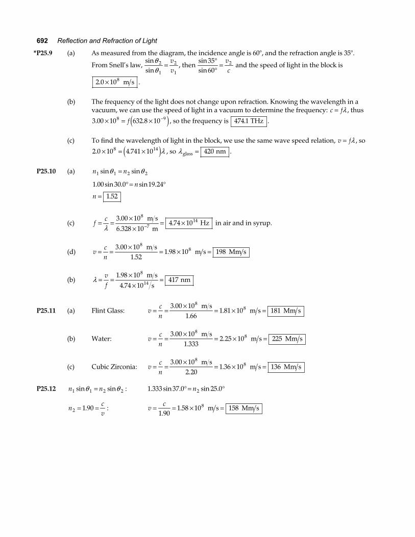
P25.13 n n1 1 2 2sin sinθ θ= : θ θ2
1 1 1
2=FHG
IKJ
−sinsinnn
θ 21 1 00 30
1 5019 5= °RST
UVW = °−sin. sin
..
θ 2 and θ 3 are alternate interior angles formed by the ray cutting parallel normals.
So, θ θ3 2 19 5= = °.
1 50 1 00
30 03 4
4
. sin . sin
.
θ θ
θ
=
= °
FIG. P25.13
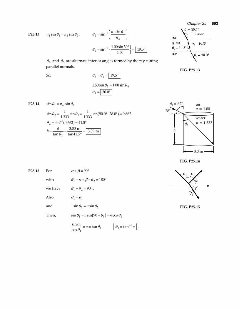
P25.14 sin sinθ θ1 2= nw
sin.
sin.
sin . . .
sin . .
tan.
.
θ θ
θ
θ
2 1
21
2
11 333
11 333
90 0 28 0 0 662
0 662 41 53 00
3 39
= = °− ° =
= = °
= =°
=
−
a fa f
hd m
tan41.5 m
water
air
28°
3.0 m
h
n = 1.00
n = 1.333
θ = 62°1
θ2
FIG. P25.14
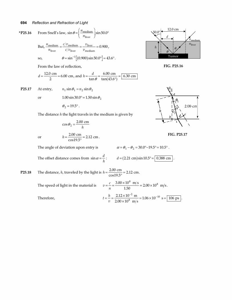
P25.15 For α β+ = °90
with ′ + + + = °θ α β θ1 2 180
we have ′ + = °θ θ1 2 90 .
Also, ′ =θ θ1 1
and 1 1 2sin sinθ θ= n .
Then, sin sin cosθ θ θ1 1 190= − =n nb g
sincos
tanθθ
θ1
11= =n θ 1
1= −tan n .
FIG. P25.15
694 Reflection and Refraction of Light
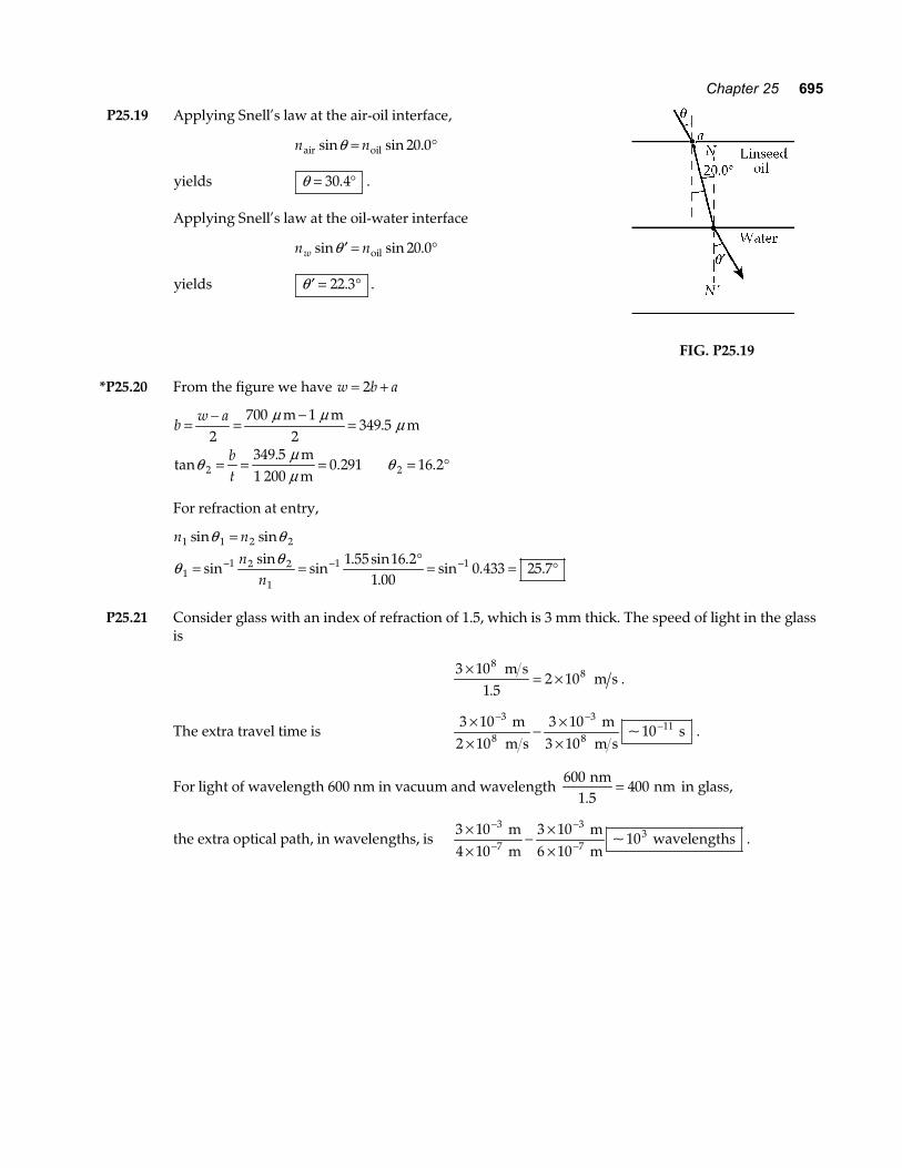
*P25.16 From Snell’s law, sin sin .θ =FHG
IKJ °
nnmedium
liver50 0
But, n
nc v
c vv
vmedium
liver
medium
liver
liver
medium= = = 0 900. ,
so, θ = ° = °−sin . sin . .1 0 900 50 0 43 6a f .
From the law of reflection,
d = =12 06 00
..
cm2
cm, and hd= =
°=
tan.
tan ..
θ6 00
43 66 30
cm cma f
Tumor
d
h θ θ
50.0°12.0 cm
nmediumnliver
FIG. P25.16
P25.17 At entry, n n1 1 2 2sin sinθ θ=
or 1 00 30 0 1 50 2. sin . . sin° = θ
θ 2 19 5= °. .
The distance h the light travels in the medium is given by
cos.θ 2
2 00= cmh
or h =°
=2 002 12
..
cmcos19.5
cm .
FIG. P25.17
The angle of deviation upon entry is α θ θ= − = °− ° = °1 2 30 0 19 5 10 5. . . .
The offset distance comes from sinα = dh
:
d = ° =2 21 10 5 0 388. sin . . cm cma f .
P25.18 The distance, h, traveled by the light is h =°
=2 002 12
.. .
cmcos19.5
cm
The speed of light in the material is vcn
= =×
= ×3 00 10
1 502 00 10
88.
.. .
m s m s
Therefore, thv
= = ××
= × =−
−2 12 101 06 10 106
210.
. . m
2.00 10 m s s ps8
Chapter 25 695
P25.19 Applying Snell’s law at the air-oil interface,
n nair oilsin sin .θ = °20 0
yields θ = °30 4. .
Applying Snell’s law at the oil-water interface
n nw sin sin .′ = °θ oil 20 0
yields ′ = °θ 22 3. .
FIG. P25.19
*P25.20 From the figure we have w b a= +2
b
w a
bt
= − =−
=
= = = = °
2700 1
349 5
349 50 291 16 22 2
m m2
m
m1 200 m
µ µµ
θµµ
θ
.
tan.
. .
For refraction at entry,
n n
nn
1 1 2 2
11 2 2
1
1 11 55 16 21 00
0 433 25 7
sin sin
sinsin
sin. sin .
.sin . .
θ θ
θ θ=
= = ° = = °− − −
P25.21 Consider glass with an index of refraction of 1.5, which is 3 mm thick. The speed of light in the glass
is
3 10
1 52 10
88×
= × m s
m s.
.
The extra travel time is 3 102 10
3 103 10
103
8
3
811×
×− ×
×
− −− m
m s m
m s s~ .
For light of wavelength 600 nm in vacuum and wavelength 600
400 nm
1.5 nm= in glass,
the extra optical path, in wavelengths, is 3 10 3 10
6 1010
3
7
3
73×
×− ×
×
−
−
−
− m
4 10 m mm
wavelengths~ .
696 Reflection and Refraction of Light
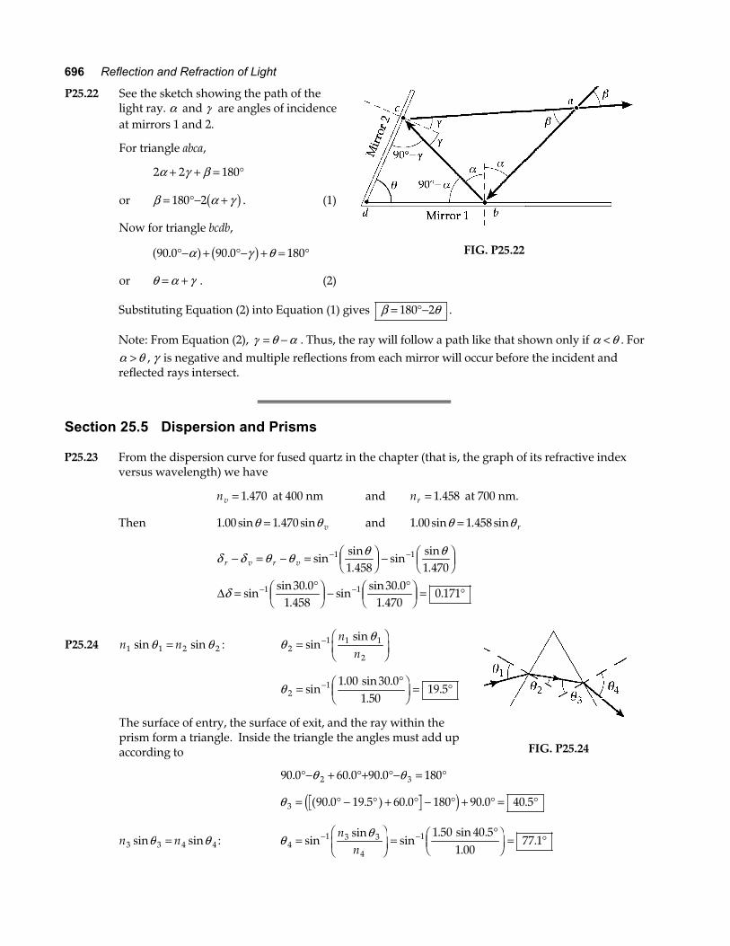
P25.22 See the sketch showing the path of the light ray. α and γ are angles of incidence at mirrors 1 and 2.
For triangle abca,
2 2 180α γ β+ + = °
or β α γ= °− +180 2b g . (1)
Now for triangle bcdb,
90 0 90 0 180. .°− + °− + = °α γ θa f b g
or θ α γ= + . (2)
FIG. P25.22
Substituting Equation (2) into Equation (1) gives β θ= °−180 2 .
Note: From Equation (2), γ θ α= − . Thus, the ray will follow a path like that shown only if α θ< . For α θ> , γ is negative and multiple reflections from each mirror will occur before the incident and reflected rays intersect.
Section 25.5 Dispersion and Prisms P25.23 From the dispersion curve for fused quartz in the chapter (that is, the graph of its refractive index
versus wavelength) we have
nv = 1 470. at 400 nm and nr = 1 458. at 700 nm.
Then 1 00 1 470. sin . sinθ θ= v and 1 00 1 458. sin . sinθ θ= r
δ δ θ θ θ θ
δ
r v r v− = − = FHGIKJ −
FHGIKJ
= °FHG
IKJ −
°FHG
IKJ = °
− −
− −
sinsin.
sinsin.
sinsin .
.sin
sin ..
.
1 1
1 1
1 458 1 47030 0
1 45830 0
1 4700 171∆
P25.24 n n1 1 2 2sin sinθ θ= : θθ
21 1 1
2=FHG
IKJ
−sinsinnn
θ 21 1 00 30 0
1 5019 5=
°FHG
IKJ = °−sin
. sin ..
.
The surface of entry, the surface of exit, and the ray within the prism form a triangle. Inside the triangle the angles must add up according to
90 0 60 0 90 0 1802 3. . .°− + °+ °− = °θ θ
FIG. P25.24
θ 3 90 0 19 5 60 0 180 90 0 40 5= ° − ° + ° − ° + ° = °( . . ) . . .d i
n n3 3 4 4sin sinθ θ= : θ θ4
1 3 3
4
1 1 50 40 51 00
77 1=FHG
IKJ =
°FHG
IKJ = °− −sin
sinsin
. sin ..
.n
n
Chapter 25 697
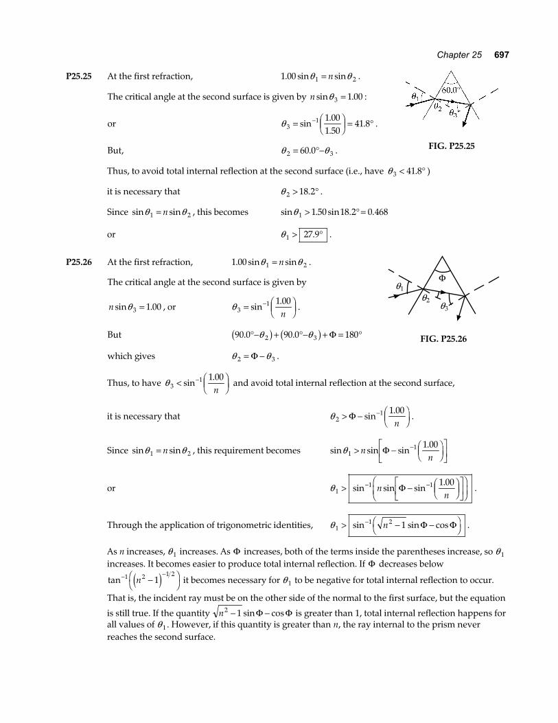
P25.25 At the first refraction, 1 00 1 2. sin sinθ θ= n .
The critical angle at the second surface is given by n sin .θ 3 1 00= :
or θ 31 1 00
1 5041 8= F
HGIKJ = °−sin
.
.. .
But, θ θ2 360 0= °−. .
FIG. P25.25
Thus, to avoid total internal reflection at the second surface (i.e., have θ 3 41 8< °. )
it is necessary that θ 2 18 2> °. .
Since sin sinθ θ1 2= n , this becomes sin . sin . .θ 1 1 50 18 2 0 468> ° =
or θ 1 27 9> °. .
P25.26 At the first refraction, 1 00 1 2. sin sinθ θ= n .
The critical angle at the second surface is given by
n sin .θ 3 1 00= , or θ 31 1 00= FHGIKJ
−sin.n
.
But 90 0 90 0 1802 3. .°− + °− + = °θ θb g b g Φ
which gives θ θ2 3= −Φ .
Φ
θ2
θ1
θ3
FIG. P25.26
Thus, to have θ 31 1 00< FHGIKJ
−sin.n
and avoid total internal reflection at the second surface,
it is necessary that θ 21 1 00> − FHGIKJ
−Φ sin.n
.
Since sin sinθ θ1 2= n , this requirement becomes sin sin sin.θ 1
1 1 00> − FHGIKJ
LNM
OQP
−nn
Φ
or θ 11 1 1 00> − F
HGIKJ
LNM
OQP
FHG
IKJ
− −sin sin sin.
nn
Φ .
Through the application of trigonometric identities, θ 11 2 1> − −FH IK−sin sin cosn Φ Φ .
As n increases, θ 1 increases. As Φ increases, both of the terms inside the parentheses increase, so θ 1 increases. It becomes easier to produce total internal reflection. If Φ decreases below
tan− −−FH IK1 2 1 2
1ne j it becomes necessary for θ 1 to be negative for total internal reflection to occur.
That is, the incident ray must be on the other side of the normal to the first surface, but the equation
is still true. If the quantity n2 1− −sin cosΦ Φ is greater than 1, total internal reflection happens for all values of θ 1 . However, if this quantity is greater than n, the ray internal to the prism never reaches the second surface.
698 Reflection and Refraction of Light
P25.27 For the incoming ray, sinsinθ θ
21=
n.
Using the figure to the right, θ 21 50 0
1 6627 48b gviolet = °F
HGIKJ = °−sin
sin ..
.
θ 21 50 0
1 6228 22b gred = °F
HGIKJ = °−sin
sin ..
. .
For the outgoing ray, θ θ3 260 0= °−.
FIG. P25.27
and sin sinθ θ4 3= n : θ 41 1 66 32 52 63 17b gviolet = ° = °−sin . sin . .
θ 41 1 62 31 78 58 56b gred = ° = °−sin . sin . . .
The angular dispersion is the difference ∆θ θ θ4 4 4 63 17 58 56 4 61= − = °− ° = °b g b gviolet red . . . .
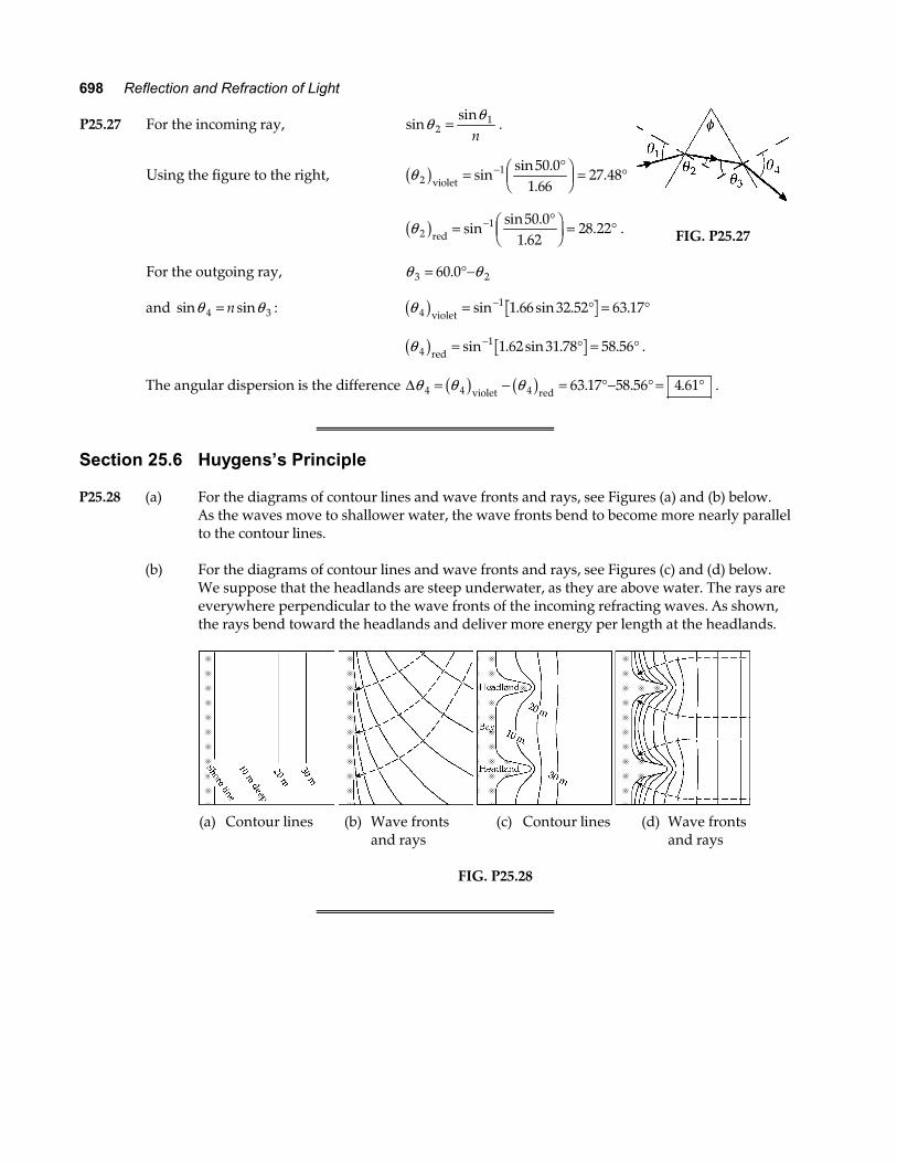
Section 25.6 Huygens’s Principle P25.28 (a) For the diagrams of contour lines and wave fronts and rays, see Figures (a) and (b) below.
As the waves move to shallower water, the wave fronts bend to become more nearly parallel to the contour lines.
(b) For the diagrams of contour lines and wave fronts and rays, see Figures (c) and (d) below. We suppose that the headlands are steep underwater, as they are above water. The rays are
everywhere perpendicular to the wave fronts of the incoming refracting waves. As shown, the rays bend toward the headlands and deliver more energy per length at the headlands.
(a) Contour lines (b) Wave fronts (c) Contour lines (d) Wave fronts and rays and rays
FIG. P25.28
Chapter 25 699
Section 25.7 Total Internal Reflection P25.29 n sinθ = 1 . From the table of refractive indices
(a) θ = FHGIKJ = °−sin
..1 1
2 41924 4
(b) θ = FHGIKJ = °−sin
..1 1
1 6637 0
(c) θ = FHGIKJ = °−sin
..1 1
1 30949 8
P25.30 (a) sinsin
θθ
2
1
2
1=
vv
and θ 2 90 0= °. at the critical angle
sin .
sin90 0 1 850
343° =
θ c
m s m s
so θ c = = °−sin . .1 0 185 10 7a f .
(b) Sound can be totally reflected if it is traveling in the medium where it travels slower: air .
(c) Sound in air falling on the wall from most directions is 100% reflected , so the wall is a
good mirror.
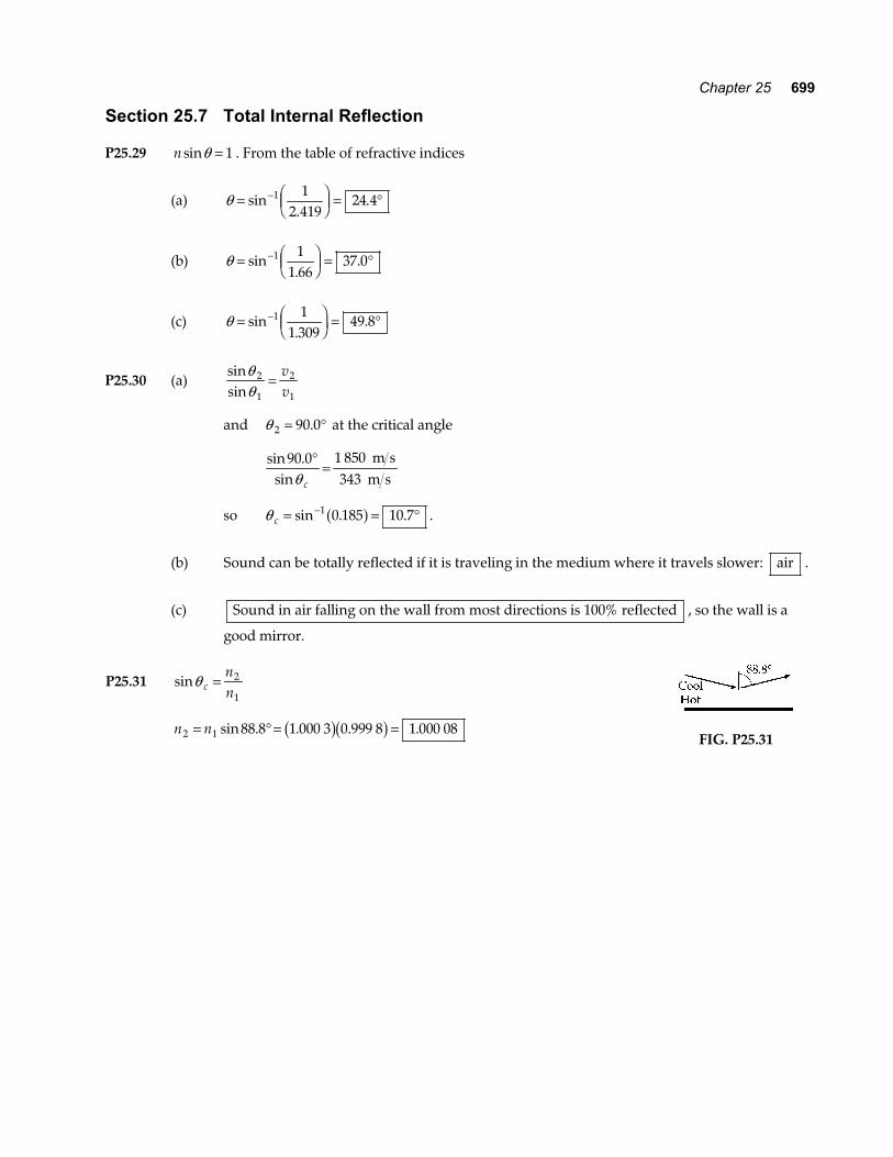
P25.31 sinθ cnn
= 2
1
n n2 1 88 8 1 000 3 0 999 8 1 000 08= ° = =sin . . . .b gb g
FIG. P25.31
700 Reflection and Refraction of Light
P25.32 For plastic with index of refraction n ≥ 1 42. surrounded by air, the critical angle for total internal
reflection is given by
θ c n= FHGIKJ ≤
FHGIKJ = °− −sin sin
..1 11 1
1 4244 8 .
In the gasoline gauge, skylight from above travels down the plastic. The rays close to the vertical are totally reflected from the sides of the slab and from both facets at the lower end of the plastic, where it is not immersed in gasoline. This light returns up inside the plastic and makes it look bright. Where the plastic is immersed in gasoline, with index of refraction about 1.50, total internal reflection should not happen. The light passes out of the lower end of the plastic with little reflected, making this part of the gauge look dark. To frustrate total internal reflection in the gasoline, the index of refraction of the plastic should be n < 2 12.
since θ c = FHGIKJ = °−sin
.
..1 1 50
2 1245 0 .
Section 25.8 Context ConnectionOptical Fibers
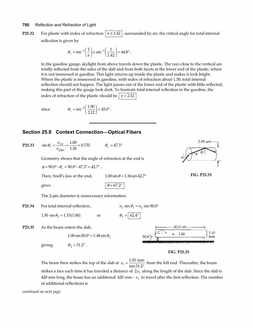
P25.33 sin..
.θ cn
n= = =air
pipe
1 001 36
0 735 θ c = °47 3.
Geometry shows that the angle of refraction at the end is
φ θ= °− = °− ° = °90 0 90 0 47 3 42 7. . . .c .
Then, Snell’s law at the end, 1 00 1 36 42 7. sin . sin .θ = °
gives θ = °67 2. .
The 2-µm diameter is unnecessary information.
FIG. P25.33
P25.34 For total internal reflection, n n1 1 2 90 0sin sin .θ = °
1 50 1 33 1 001. sin . ( . )θ = or θ 1 62 4= °.
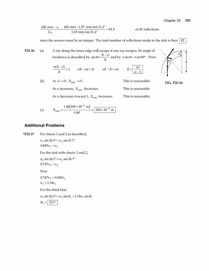
P25.35 As the beam enters the slab,
1 00 50 0 1 48 2. sin . . sin° = θ
giving θ 2 31 2= °. .
FIG. P25.35
The beam then strikes the top of the slab at x11 55
31 2=
°.
tan . mm
from the left end. Thereafter, the beam
strikes a face each time it has traveled a distance of 2 1x along the length of the slab. Since the slab is 420 mm long, the beam has an additional 420 1 mm − x to travel after the first reflection. The number of additional reflections is
continued on next page
Chapter 25 701
420
21 55 31 2
3 10 31 281 51
1
mm 420 mm mm mm
−=
− °°
=x
x. tan .
. tan .. or 81 reflections
since the answer must be an integer. The total number of reflections made in the slab is then 82 .
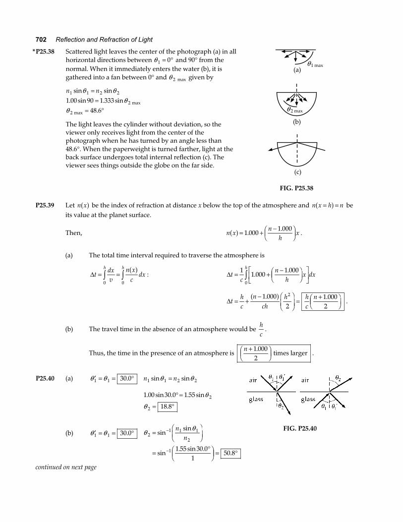
P25.36 (a) A ray along the inner edge will escape if any ray escapes. Its angle of
incidence is described by sinθ = −R dR
and by n sin sinθ > °1 90 . Then
n R d
R−
>a f
1 nR nd R− > nR R nd− > Rnd
n>
− 1.
(b) As d → 0 , Rmin → 0 . This is reasonable.
As n increases, Rmin decreases. This is reasonable.
As n decreases toward 1, Rmin increases. This is reasonable.
(c) Rmin
.
.=
×= ×
−−
1 40 100 10
0 40350 10
66
m m
e j
FIG. P25.36
Additional Problems
*P25.37 For sheets 1 and 2 as described,
n n
n n1 2
1 2
26 5 31 70 849
sin . sin ..
° = °=
For the trial with sheets 3 and 2,
n n
n n3 2
3 2
26 5 36 70 747
sin . sin ..
° = °=
Now
0 747 0 849
1 143 1
3 1
. ..
n nn n
==
For the third trial,
n n n1 3 3 1 3
3
26 5 1 14
23 1
sin . sin . sin
.
° = =
= °
θ θ
θ
702 Reflection and Refraction of Light
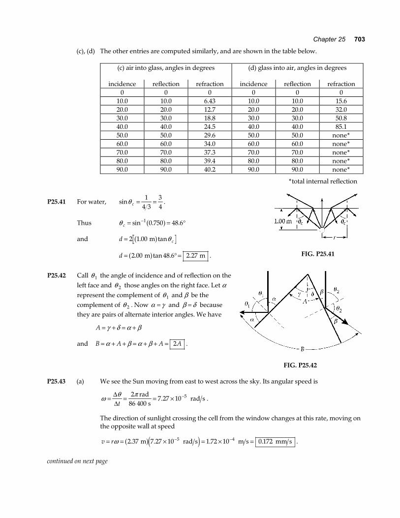
*P25.38 Scattered light leaves the center of the photograph (a) in all horizontal directions between θ 1 0= ° and 90° from the normal. When it immediately enters the water (b), it is gathered into a fan between 0° and θ 2 max given by
n n1 1 2 2
2
2
1 00 90 1 33348 6
sin sin. sin . sin
.
θ θθ
θ
==
= ° max
max
The light leaves the cylinder without deviation, so the viewer only receives light from the center of the photograph when he has turned by an angle less than 48.6°. When the paperweight is turned farther, light at the back surface undergoes total internal reflection (c). The viewer sees things outside the globe on the far side.
θ 1 max
(a)
θ 2 max
(b)
(c)
FIG. P25.38 P25.39 Let n xa f be the index of refraction at distance x below the top of the atmosphere and n x h n= =a f be
its value at the planet surface.
Then, n xn
hxa f = + −F
HGIKJ1 000
1 000.
..
(a) The total time interval required to traverse the atmosphere is
∆tdxv
n xc
dxh h
= =z z0 0
a f: ∆t
cn
hx dx
h
= + −FHG
IKJ
LNM
OQPz1 1 000
1 000
0
..
∆thc
nch
h hc
n= +− F
HGIKJ =
+FHG
IKJ
1 0002
1 0002
2. .a f.
(b) The travel time in the absence of an atmosphere would be hc
.
Thus, the time in the presence of an atmosphere is n +FHG
IKJ
1 0002.
times larger .
P25.40 (a) ′ = = °θ θ1 1 30 0. n n1 1 2 2sin sinθ θ=
1 00 30 0 1 55
18 82
2
. sin . . sin
.
° =
= °
θ
θ
(b)
′ = = °θ θ1 1 30 0.
θ θ2
1 1 1
2
1 1 55 30 01
50 8
=FHG
IKJ
= °FHG
IKJ = °
−
−
sinsin
sin. sin .
.
nn
FIG. P25.40
continued on next page
Chapter 25 703
(c), (d) The other entries are computed similarly, and are shown in the table below.
(c) air into glass, angles in degrees
(d) glass into air, angles in degrees
incidence reflection refraction incidence reflection refraction 0 0 0 0 0 0 10.0 10.0 6.43 10.0 10.0 15.6 20.0 20.0 12.7 20.0 20.0 32.0 30.0 30.0 18.8 30.0 30.0 50.8 40.0 40.0 24.5 40.0 40.0 85.1 50.0 50.0 29.6 50.0 50.0 none* 60.0 60.0 34.0 60.0 60.0 none* 70.0 70.0 37.3 70.0 70.0 none* 80.0 80.0 39.4 80.0 80.0 none* 90.0 90.0 40.2 90.0 90.0 none*
*total internal reflection
P25.41 For water, sinθ c = =14 3
34
.
Thus θ c = = °−sin . .1 0 750 48 6a f
and d c= 2 1 00. tan ma f θ
d = ° =2 00 48 6 2 27. tan . . m ma f .
FIG. P25.41
P25.42 Call θ 1 the angle of incidence and of reflection on the
left face and θ 2 those angles on the right face. Let α represent the complement of θ 1 and β be the complement of θ 2 . Now α γ= and β δ= because they are pairs of alternate interior angles. We have
A = + = +γ δ α β
and B A A A= + + = + + =α β α β 2 .
FIG. P25.42
P25.43 (a) We see the Sun moving from east to west across the sky. Its angular speed is
ω θ π= = = × −∆∆t
27 27 10 5 rad
86 400 s rad s. .
The direction of sunlight crossing the cell from the window changes at this rate, moving on the opposite wall at speed
v r= = × = × =− −ω 2 37 7 27 10 1 72 10 0 1725 4. . . . m rad s m s mm sa fe j .
continued on next page
704 Reflection and Refraction of Light
(b) The mirror folds into the cell the motion that would occur in a room twice as wide:
v r= = =ω 2 0 174 0 345. . mm s mm sb g .
(c), (d) As the Sun moves southward and upward at 50.0°, we may regard the corner of the window
as fixed, and both patches of light move northward and downward at 50.0° .
P25.44 (a) 45 0. ° as shown in the first figure to the right.
(b) Yes
If grazing angle is halved, the number of reflections from the side faces is doubled.
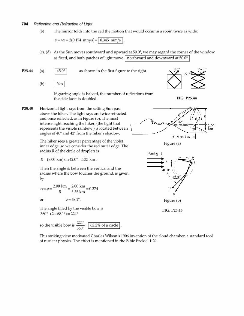
FIG. P25.44 P25.45 Horizontal light rays from the setting Sun pass
above the hiker. The light rays are twice refracted and once reflected, as in Figure (b). The most intense light reaching the hiker, (the light that represents the visible rainbow,) is located between angles of 40° and 42° from the hiker’s shadow.
The hiker sees a greater percentage of the violet inner edge, so we consider the red outer edge. The radius R of the circle of droplets is
R = ° =8 00 42 0 5 35. sin . . km kma f .
Then the angle φ, between the vertical and the radius where the bow touches the ground, is given by
cos. .
.φ = = =2 00 2 000 374
km km5.35 kmR
or φ = °68 1. .
The angle filled by the visible bow is 360 2 68 1 224°− × ° = °.a f
so the visible bow is 224360
62 2%°°
= . of a circle .
Figure (a)
Figure (b)
FIG. P25.45
This striking view motivated Charles Wilson’s 1906 invention of the cloud chamber, a standard tool of nuclear physics. The effect is mentioned in the Bible Ezekiel 1:29.
Chapter 25 705
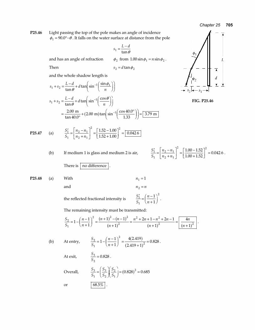
P25.46 Light passing the top of the pole makes an angle of incidence φ θ1 90 0= °−. . It falls on the water surface at distance from the pole
sL d
1 = −tanθ
and has an angle of refraction φ 2 from 1 00 1 2. sin sinφ φ= n .
Then s d2 2= tanφ
and the whole shadow length is
s sL d
dn1 2
1 1+ = − + FHGIKJ
FHG
IKJ
−
tantan sin
sinθ
φ
s sL d
dn1 2
1
12 0040 0
2 0040 0
1 333 79
+ = − + FHGIKJ
FHG
IKJ
=°
+ °FHG
IKJ
FHG
IKJ =
−
−
tantan sin
cos
.tan .
. tan sincos .
..
θθ
m m ma f
FIG. P25.46
P25.47 (a) ′ =
−+
LNM
OQP
= −+
LNM
OQP =
SS
n nn n
1
1
2 1
2 1
2 21 52 1 001 52 1 00
0 042 6. .. .
.
(b) If medium 1 is glass and medium 2 is air, ′ =
−+
LNM
OQP
= −+
LNM
OQP =
SS
n nn n
1
1
2 1
2 1
2 21 00 1 521 00 1 52
0 042 6. .. .
. .
There is no difference .
P25.48 (a) With n1 1=
and n n2 =
the reflected fractional intensity is ′
= −+FHGIKJ
SS
nn
1
1
211
.
The remaining intensity must be transmitted:
SS
nn
n n
n
n n n n
n
n
n2
1
2 2 2
2
2 2
2 2111
1 1
1
2 1 2 1
1
4
1= − −
+FHGIKJ =
+ − −
+= + + − + −
+=
+a f a fa f a f a f .
(b) At entry, SS
nn
2
1
2
2111
4 2 419
2 419 10 828= − −
+FHGIKJ =
+=
.
..
a fa f .
At exit, SS
3
20 828= . .
Overall, SS
SS
SS
3
1
3
2
2
1
20 828 0 685=FHGIKJFHGIKJ = =. .a f
or 68 5%. .
706 Reflection and Refraction of Light
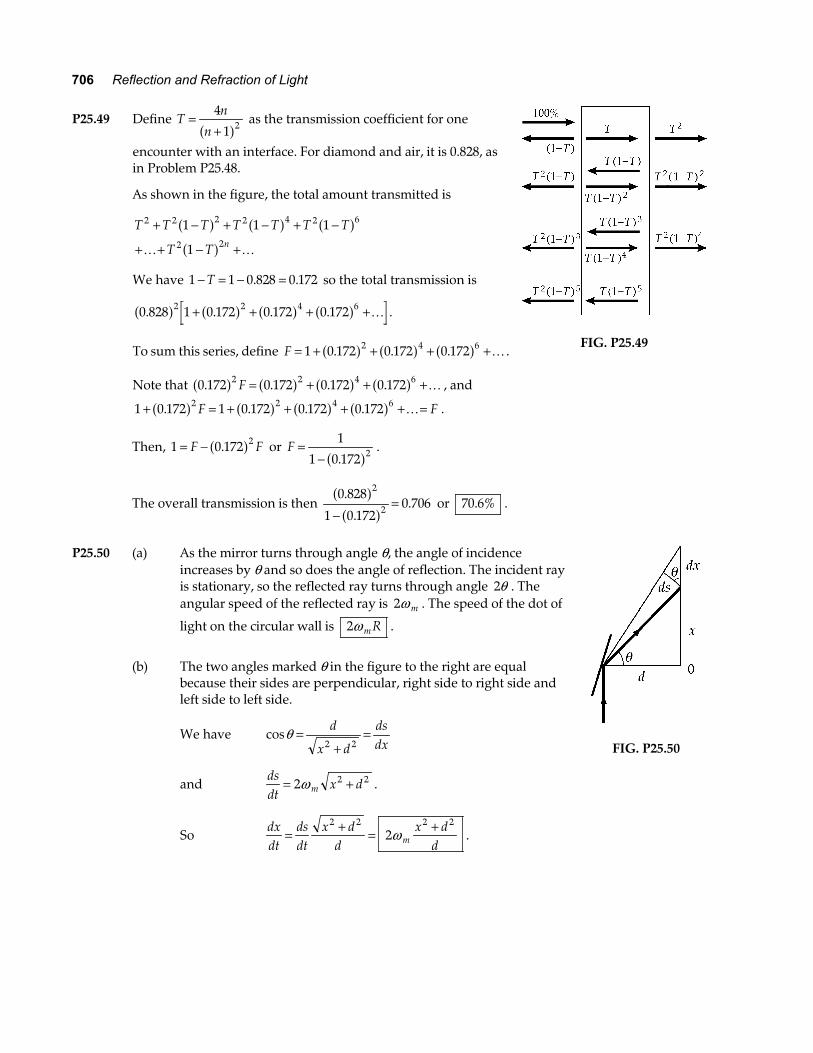
P25.49 Define Tn
n=
+4
1 2a f as the transmission coefficient for one
encounter with an interface. For diamond and air, it is 0.828, as in Problem P25.48.
As shown in the figure, the total amount transmitted is
T T T T T T T
T T n
2 2 2 2 4 2 6
2 2
1 1 1
1
+ − + − + −
+ + − +
a f a f a fa fK K
We have 1 1 0 828 0 172− = − =T . . so the total transmission is
0 828 1 0 172 0 172 0 1722 2 4 6. . . .a f a f a f a f+ + + +K .
To sum this series, define F = + + + +1 0 172 0 172 0 1722 4 6. . .a f a f a f K .
Note that 0 172 0 172 0 172 0 1722 2 4 6. . . .a f a f a f a fF = + + +K , and
1 0 172 1 0 172 0 172 0 1722 2 4 6+ = + + + + =. . . .a f a f a f a fF FK .
FIG. P25.49
Then, 1 0 172 2= −F F.a f or F =−
1
1 0 172 2.a f .
The overall transmission is then 0 828
1 0 1720 706
2
2
.
..
a fa f−
= or 70 6%. .
P25.50 (a) As the mirror turns through angle θ, the angle of incidence
increases by θ and so does the angle of reflection. The incident ray is stationary, so the reflected ray turns through angle 2θ . The angular speed of the reflected ray is 2ω m . The speed of the dot of
light on the circular wall is 2ω mR .
(b) The two angles marked θ in the figure to the right are equal
because their sides are perpendicular, right side to right side and left side to left side.
We have cosθ =+
=d
x d
dsdx2 2
and dsdt
x dm= +2 2 2ω .
So dxdt
dsdt
x dd
x ddm= + = +2 2 2 2
2ω .
FIG. P25.50
Chapter 25 707
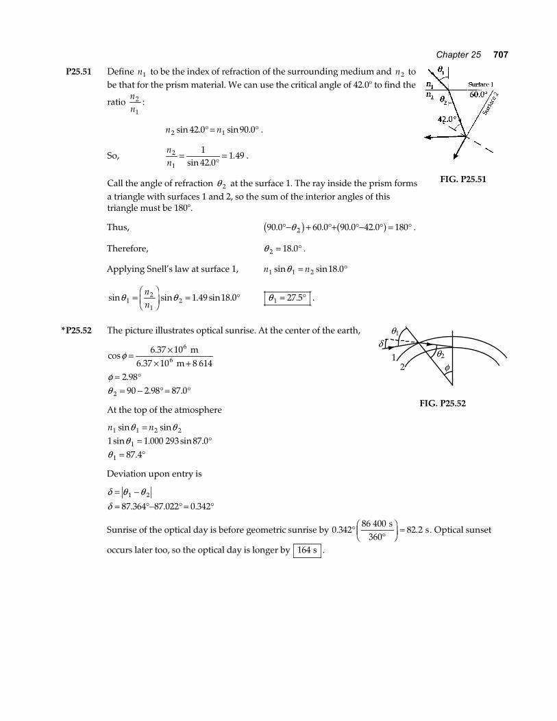
P25.51 Define n1 to be the index of refraction of the surrounding medium and n2 to be that for the prism material. We can use the critical angle of 42.0° to find the
ratio nn
2
1:
n n2 142 0 90 0sin . sin .° = ° .
So, nn
2
1
142 0
1 49=°
=sin .
. .
Call the angle of refraction θ 2 at the surface 1. The ray inside the prism forms a triangle with surfaces 1 and 2, so the sum of the interior angles of this triangle must be 180°.
FIG. P25.51
Thus, 90 0 60 0 90 0 42 0 1802. . . .°− + °+ °− ° = °θb g a f .
Therefore, θ 2 18 0= °. .
Applying Snell’s law at surface 1, n n1 1 2 18 0sin sin .θ = °
sin sin . sin .θ θ12
12 1 49 18 0=
FHGIKJ = °
nn
θ 1 27 5= °. .
*P25.52 The picture illustrates optical sunrise. At the center of the earth,
cos.
.. .
φ
φθ
= ×× +
= °= − ° = °
6 37 108 614
2 9890 2 98 87 0
6
2
m6.37 10 m6
At the top of the atmosphere
n n1 1 2 2
1
1
1 1 000 293 87 087 4
sin sinsin . sin .
.
θ θθ
θ
== °
= °
δ1
2
θ1
θ2
φ
FIG. P25.52
Deviation upon entry is
δ θ θδ
= −= °− ° = °
1 2
87 364 87 022 0 342. . .
Sunrise of the optical day is before geometric sunrise by 0 34286 400
82 2. .°°
FHG
IKJ =
s360
s. Optical sunset
occurs later too, so the optical day is longer by 164 s .
708 Reflection and Refraction of Light
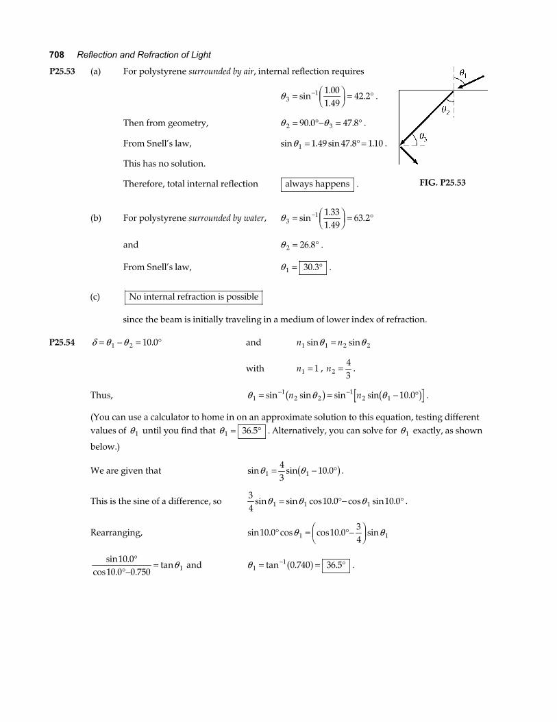
P25.53 (a) For polystyrene surrounded by air, internal reflection requires
θ 31 1 00
1 4942 2= F
HGIKJ = °−sin
.
.. .
Then from geometry, θ θ2 390 0 47 8= °− = °. . .
From Snell’s law, sin . sin . .θ 1 1 49 47 8 1 10= ° = .
This has no solution.
Therefore, total internal reflection always happens .
(b) For polystyrene surrounded by water, θ 31 1 33
1 4963 2= F
HGIKJ = °−sin
.
..
and θ 2 26 8= °. .
From Snell’s law, θ 1 30 3= °. .
FIG. P25.53
(c) No internal refraction is possible
since the beam is initially traveling in a medium of lower index of refraction. P25.54 δ θ θ= − = °1 2 10 0. and n n1 1 2 2sin sinθ θ=
with n1 1= , n243
= .
Thus, θ θ θ11
2 21
2 1 10 0= = − °− −sin sin sin sin .n nb g b g .
(You can use a calculator to home in on an approximate solution to this equation, testing different values of θ 1 until you find that θ 1 36 5= °. . Alternatively, you can solve for θ 1 exactly, as shown
below.)
We are given that sin sin .θ θ1 143
10 0= − °b g .
This is the sine of a difference, so 34
10 0 10 01 1 1sin sin cos . cos sin .θ θ θ= °− ° .
Rearranging, sin . cos cos . sin10 0 10 0341 1° = °−F
HGIKJθ θ
sin .
cos . .tan
10 010 0 0 750 1
°°−
= θ and θ 11 0 740 36 5= = °−tan . .a f .
Chapter 25 709
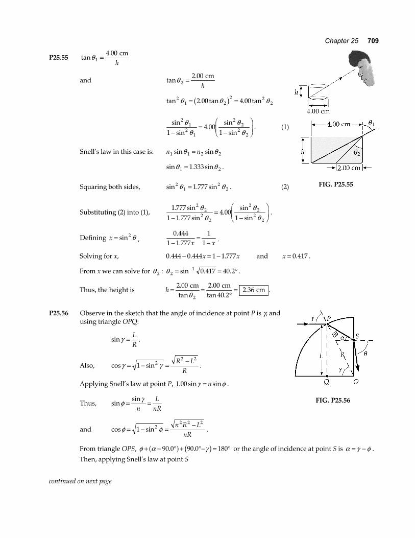
P25.55 tan.θ 1
4 00= cmh
and tan.θ 2
2 00= cmh
tan . tan . tan21 2
2 222 00 4 00θ θ θ= =b g
sin
sin.
sinsin
21
21
22
221
4 001
θθ
θθ−
=−
FHG
IKJ . (1)
Snell’s law in this case is: n n1 1 2 2sin sinθ θ=
sin . sinθ θ1 21 333= . Squaring both sides, sin . sin2
12
21 777θ θ= . (2)
Substituting (2) into (1), 1 777
1 1 7774 00
1
22
22
22
22
. sin. sin
.sin
sinθ
θθ
θ−=
−
FHG
IKJ .
Defining x = sin2 θ , 0 444
1 1 7771
1..−
=−x x .
FIG. P25.55
Solving for x, 0 444 0 444 1 1 777. . .− = −x x and x = 0 417. .
From x we can solve for θ 2 : θ 21 0 417 40 2= = °−sin . . .
Thus, the height is h = =°
=2 00 2 0040 2
2 362
.tan
.tan .
.cm cm
cmθ
.
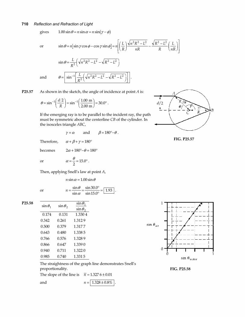
P25.56 Observe in the sketch that the angle of incidence at point P is γ, and
using triangle OPQ:
sinγ = LR
.
Also, cos sinγ γ= − = −1 2
2 2R LR
.
Applying Snell’s law at point P, 1 00. sin sinγ φ= n .
Thus, sinsinφ γ= =
nL
nR
and cos sinφ φ= − = −1 2
2 2 2n R LnR
.
FIG. P25.56
From triangle OPS, φ α γ+ + ° + °− = °90 0 90 0 180. .a f b g or the angle of incidence at point S is α γ φ= − .
Then, applying Snell’s law at point S
continued on next page
710 Reflection and Refraction of Light
gives 1 00. sin sin sinθ α γ φ= = −n n b g
or sin sin cos cos sinθ γ φ γ φ= − = FHGIKJ
− − − FHGIKJ
LNMM
OQPPn n
LR
n R LnR
R LR
LnR
2 2 2 2 2
sinθ = − − −FH IKL
Rn R L R L2
2 2 2 2 2
and θ = − − −FH IKLNM
OQP
−sin 12
2 2 2 2 2LR
n R L R L .
P25.57 As shown in the sketch, the angle of incidence at point A is:
θ = FHGIKJ =
FHG
IKJ = °− −sin sin
..1 12 1 00
30 0dR
m2.00 m
.
If the emerging ray is to be parallel to the incident ray, the path must be symmetric about the centerline CB of the cylinder. In the isosceles triangle ABC,
γ α= and β θ= °−180 .
Therefore, α β γ+ + = °180
becomes 2 180 180α θ+ °− = °
or α θ= = °2
15 0. .
Then, applying Snell’s law at point A,
n sin . sinα θ= 1 00
or n = = °°
=sinsin
sin .sin .
.θα
30 015 0
1 93 .
FIG. P25.57
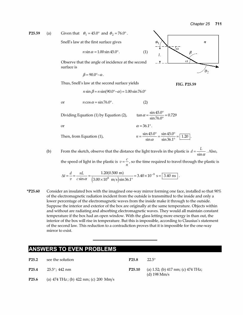
P25.58
sin sinsinsin
θ θ θθ1 2
1
2
0.1740.3420.5000.6430.7660.8660.9400.985
0.1310.2610.3790.4800.5760.6470.7110.740
1.330 41.312 91.317 71.338 51.328 91.339 01.322 01.331 5
The straightness of the graph line demonstrates Snell’s proportionality.
The slope of the line is n = ±1 327 6 0 01. .
and n = ±1 328 0 8%. . .
FIG. P25.58
Chapter 25 711
P25.59 (a) Given that θ 1 45 0= °. and θ 2 76 0= °. .
Snell’s law at the first surface gives n sin . sin . .α = °1 00 45 0 (1) Observe that the angle of incidence at the second
surface is
β α= °−90 0. .
Thus, Snell’s law at the second surface yields
n nsin sin . . sin .β α= °− = °90 0 1 00 76 0a f or n cos sin . .α = °76 0 (2)
FIG. P25.59
Dividing Equation (1) by Equation (2), tansin .sin .
.α = °°
=45 076 0
0 729
or α = °36 1. .
Then, from Equation (1), n = ° = °°
=sin .sin
sin .sin .
. .45 0 45 0
36 11 20
α
(b) From the sketch, observe that the distance the light travels in the plastic is dL=
sinα. Also,
the speed of light in the plastic is vcn
= , so the time required to travel through the plastic is
∆tdv
nLc
= = =× °
= × =−
sin. .
. sin .. .
α1 20 0 500
3 00 10 36 13 40 10 3 40
89 m
m s s ns
a fe j
.
*P25.60 Consider an insulated box with the imagined one-way mirror forming one face, installed so that 90%
of the electromagnetic radiation incident from the outside is transmitted to the inside and only a lower percentage of the electromagnetic waves from the inside make it through to the outside. Suppose the interior and exterior of the box are originally at the same temperature. Objects within and without are radiating and absorbing electromagnetic waves. They would all maintain constant temperature if the box had an open window. With the glass letting more energy in than out, the interior of the box will rise in temperature. But this is impossible, according to Clausius’s statement of the second law. This reduction to a contradiction proves that it is impossible for the one-way mirror to exist.
ANSWERS TO EVEN PROBLEMS P25.2 see the solution P25.4 25 5. ° ; 442 nm P25.6 (a) 474 THz ; (b) 422 nm; (c) 200 Mm s
P25.8 22 5. ° P25.10 (a) 1.52; (b) 417 nm; (c) 474 THz; (d) 198 Mm/s
712 Reflection and Refraction of Light
P25.12 158 Mm/s P25.14 3 39. m P25.16 6.30 cm P25.18 106 ps P25.20 25.7° P25.22 see the solution P25.24 30.0° and 19.5° at entry, 40.5° and 77.1° at
exit
P25.26 sin sin cos− − −FH IK1 2 1n Φ Φ
P25.28 see the solution P25.30 (a) 10.7°; (b) air; (c) sound in air falling on the wall from
most directions is 100% reflected P25.32 Skylight incident from the above travels
down the plastic. If the index of refraction of the plastic is greater than 1.41, the rays close in direction to the vertical are totally reflected from the side walls of the slab and from both facets at the bottom of the plastic, where it is not immersed in gasoline. This light returns up inside the plastic and makes it look bright. Where the plastic is immersed in gasoline, total internal reflection is frustrated and the downward-propagating light passes from the plastic out into the gasoline. Little light is reflected up, and the gauge looks dark.
P25.34 62.4°
P25.36 (a) dn
n − 1; (b) yes, yes, yes; (c) 350 mµ
P25.38 Scattered light leaving the photograph in
all forward horizontal directions in air is gathered by refraction into a fan in the water of half-angle 48.6°. At larger angles I see things on the other side of the globe, reflected by total internal reflection at the back surface of the cylinder.
P25.40 (a) see the solution, the angles are
′ = °θ 1 30 0. and θ 2 18 8= °. ; (b) see the solution, the angles are
′ = °θ 1 30 0. and θ 2 50 8= °. ; (c) see the solution; (d) see the solution P25.42 see the solution P25.44 (a) 45.0°; (b) yes, such as 67.5°, see the solution P25.46 3.79 m P25.48 (b) 68.5%
P25.50 (a) 2R mω ; (b) 2 2 2ω m x d
d
+e j
P25.52 164 s P25.54 36 5. °
P25.56 sin− − − −FH IKLNM
OQP
12
2 2 2 2 2LR
n R L R L
P25.58 see the solution; n = = ±slope 1 328 0 8%. . P25.60 see the solution