Embed Size (px)
Citation preview
Refraction & Lenses
Refraction of Light
When a ray of light traveling through a transparent medium encounters a boundary leading into another transparent medium, part of the ray is reflected and part of the ray enters the second medium
The ray that enters the second medium is bent at the boundary
This bending of the ray is called refraction
Refraction of Light, cont
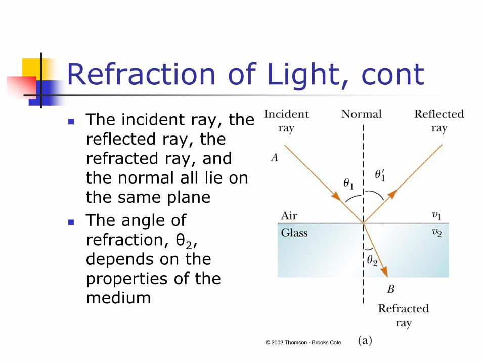
The incident ray, the reflected ray, the refracted ray, and the normal all lie on the same plane
The angle of refraction, θ2, depends on the properties of the medium
Following the Reflected and Refracted Rays
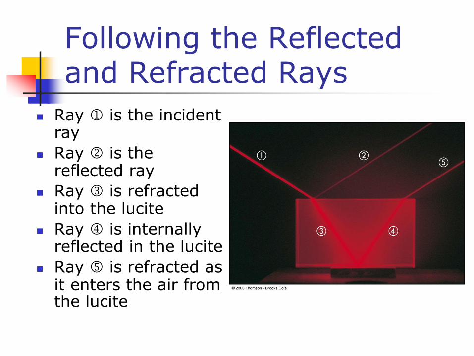
Ray is the incident ray
Ray is the reflected ray
Ray is refracted into the lucite
Ray is internally reflected in the lucite
Ray is refracted as it enters the air from the lucite
More About Refraction
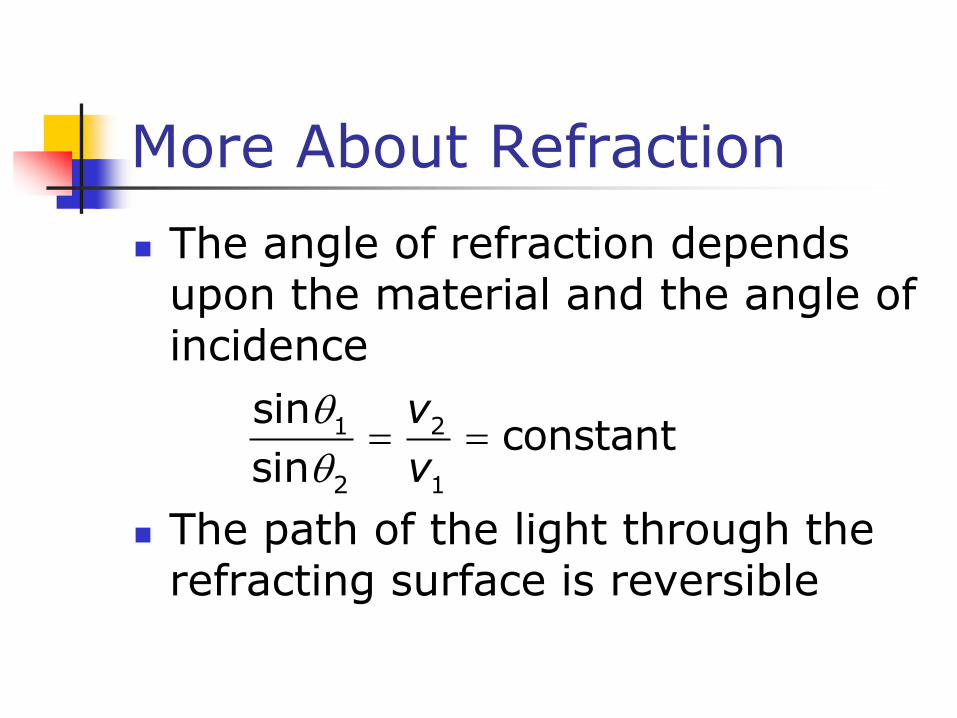
The angle of refraction depends upon the material and the angle of incidence
The path of the light through the refracting surface is reversible
1 2
2 1
sinconstant
sin
v
v
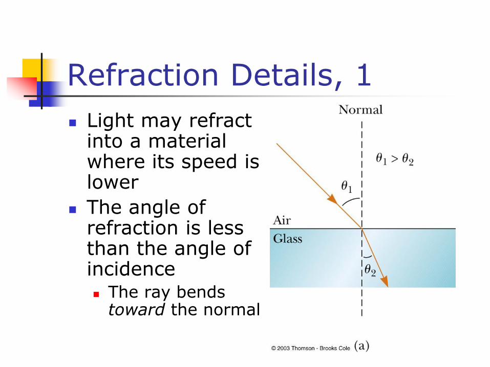
Refraction Details, 1
Light may refract into a material where its speed is lower
The angle of refraction is less than the angle of incidence The ray bends
toward the normal
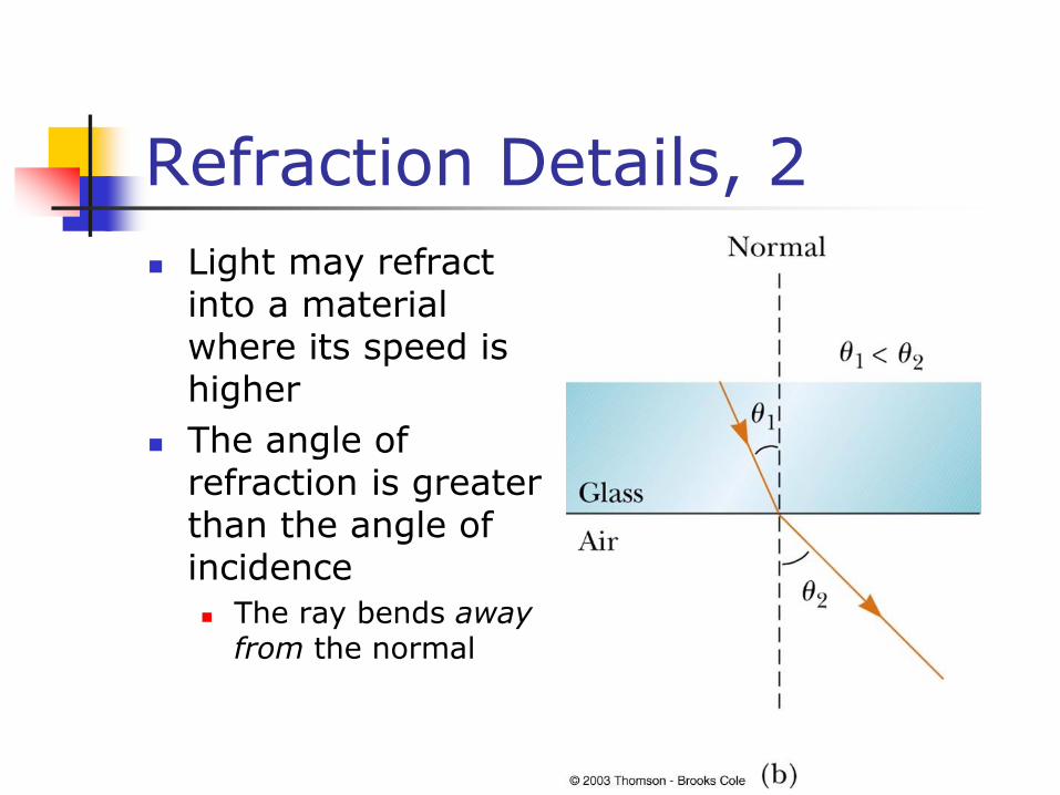
Refraction Details, 2
Light may refract into a material where its speed is higher
The angle of refraction is greater than the angle of incidence
The ray bends away from the normal
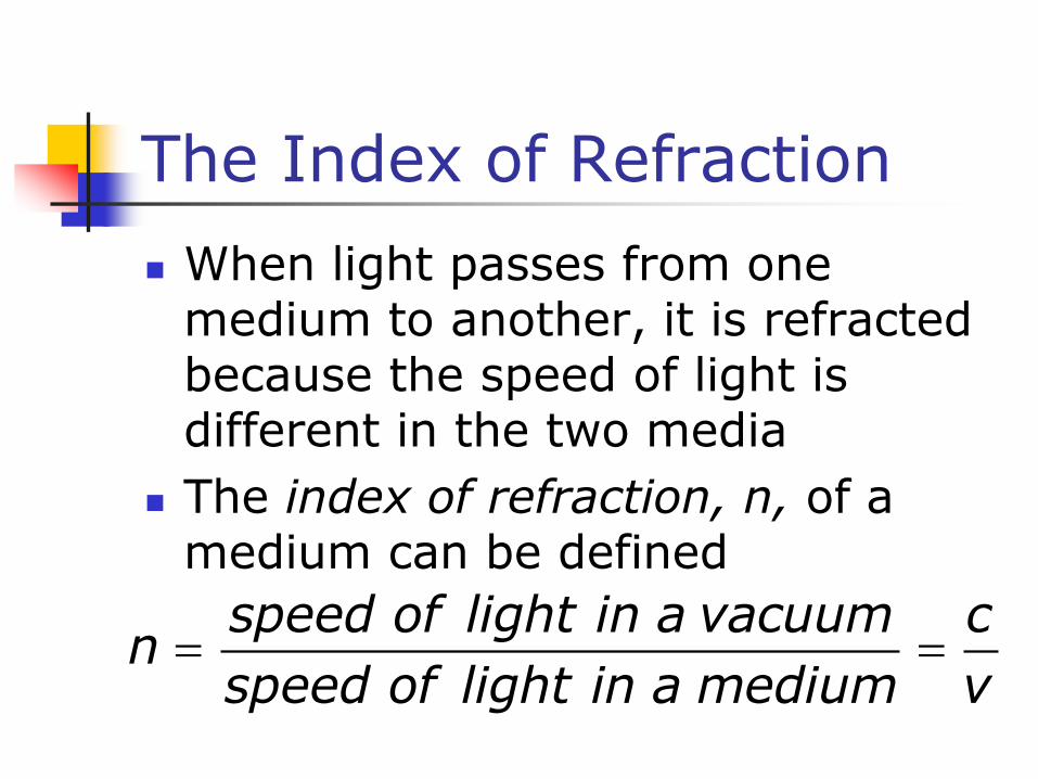
The Index of Refraction
When light passes from one medium to another, it is refracted because the speed of light is different in the two media
The index of refraction, n, of a medium can be defined
speed of light in a vacuum cn
speed of light in a medium v
Index of Refraction, cont
For a vacuum, n = 1
For other media, n > 1
n is a unitless ratio
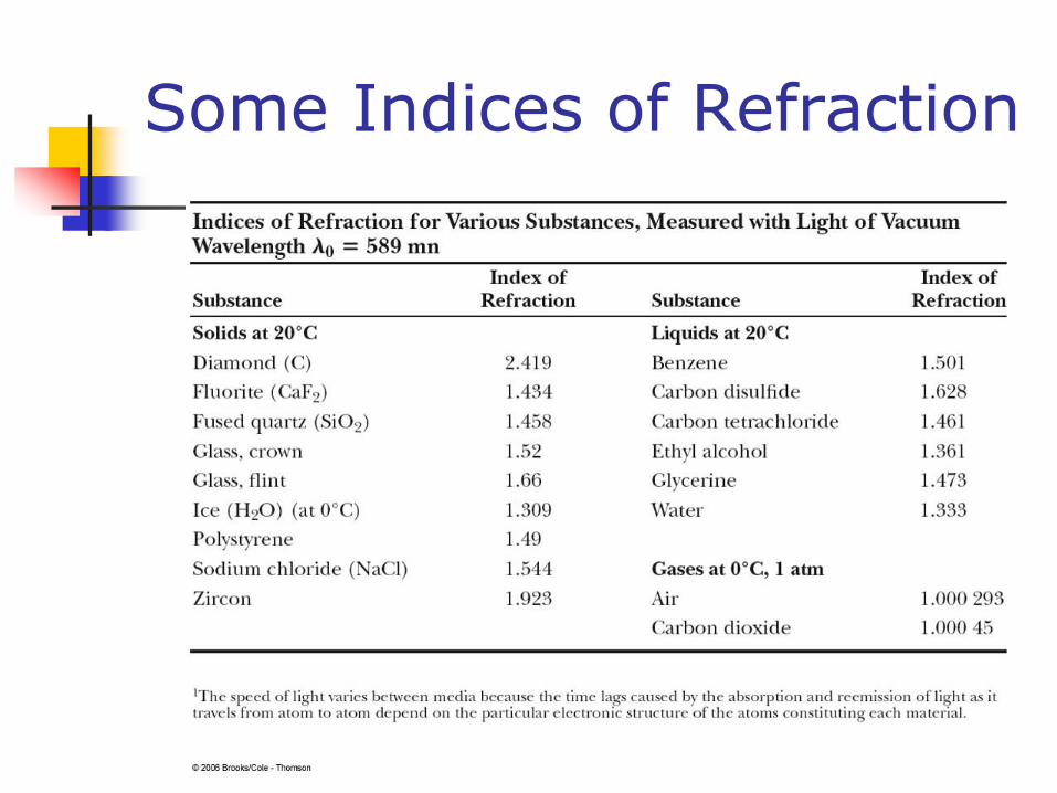
Some Indices of Refraction
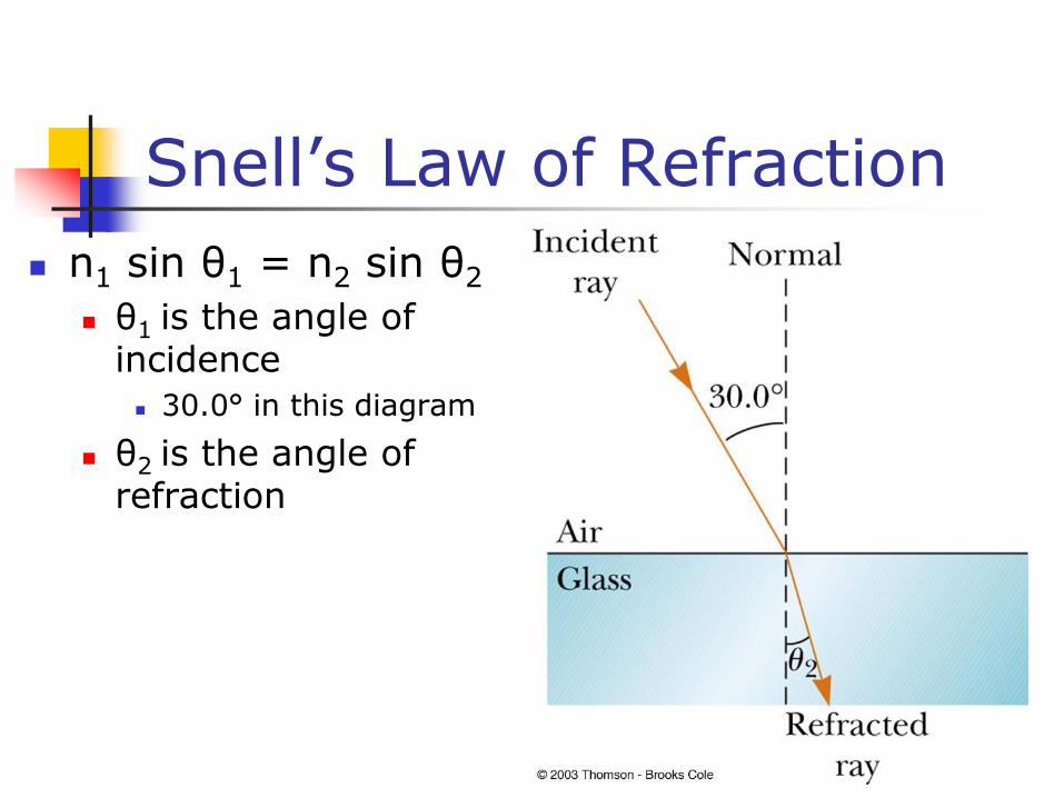
Snell’s Law of Refraction
n1 sin θ1 = n2 sin θ2
θ1 is the angle of incidence
30.0° in this diagram
θ2 is the angle of refraction
Using Spectra to Identify Gases
All hot, low pressure gases emit their own characteristic spectra
The particular wavelengths emitted by a gas serve as “fingerprints” of that gas
Some uses of spectral analysis
Identification of molecules
Identification of elements in distant stars
Identification of minerals
The Rainbow
A ray of light strikes a drop of water in the atmosphere
It undergoes both reflection and refraction
First refraction at the front of the drop
Violet light will deviate the most
Red light will deviate the least
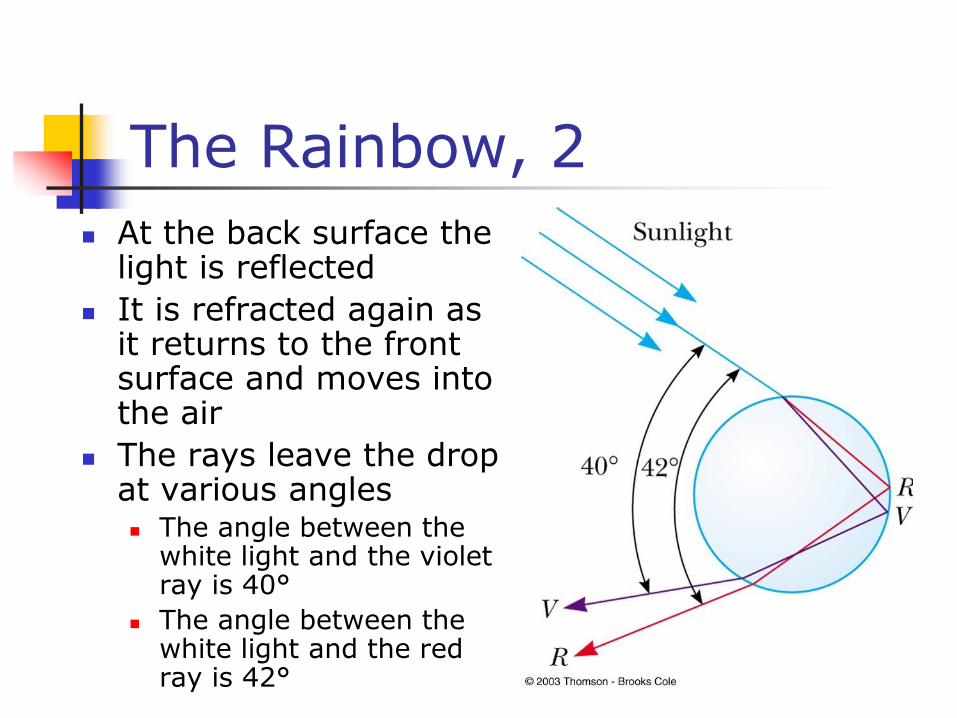
The Rainbow, 2
At the back surface the light is reflected
It is refracted again as it returns to the front surface and moves into the air
The rays leave the drop at various angles The angle between the
white light and the violet ray is 40°
The angle between the white light and the red ray is 42°
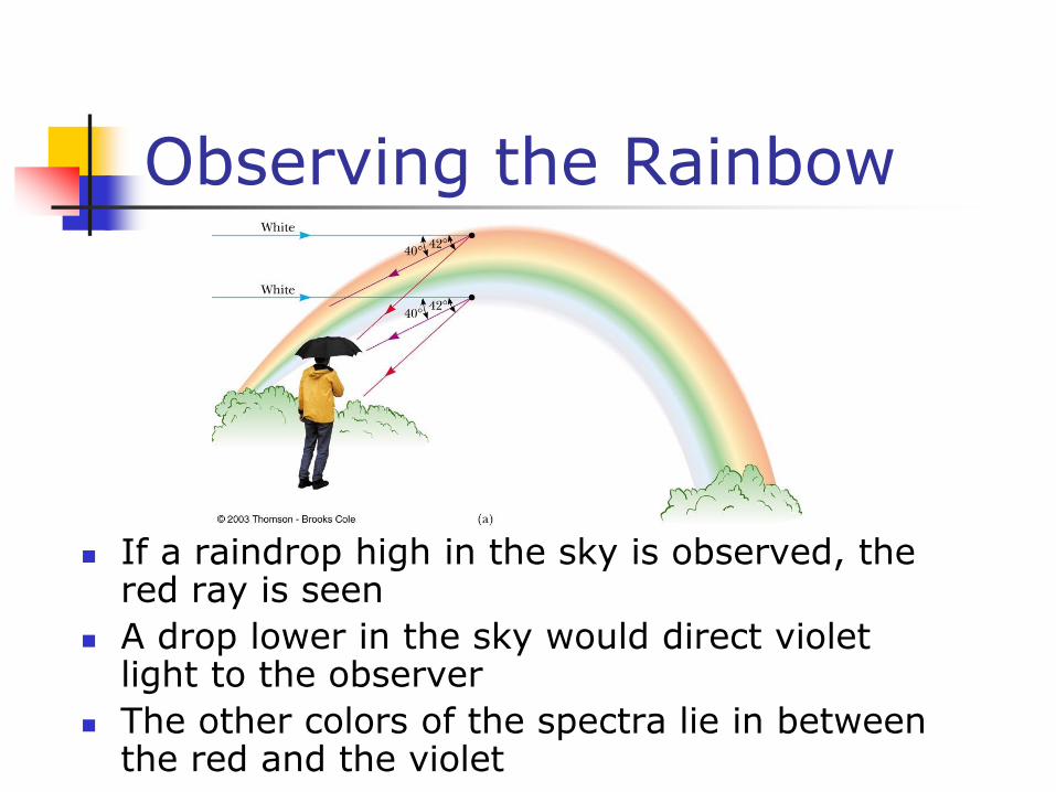
Observing the Rainbow
If a raindrop high in the sky is observed, the red ray is seen
A drop lower in the sky would direct violet light to the observer
The other colors of the spectra lie in between the red and the violet
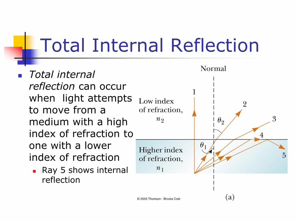
Total Internal Reflection
Total internal reflection can occur when light attempts to move from a medium with a high index of refraction to one with a lower index of refraction
Ray 5 shows internal reflection
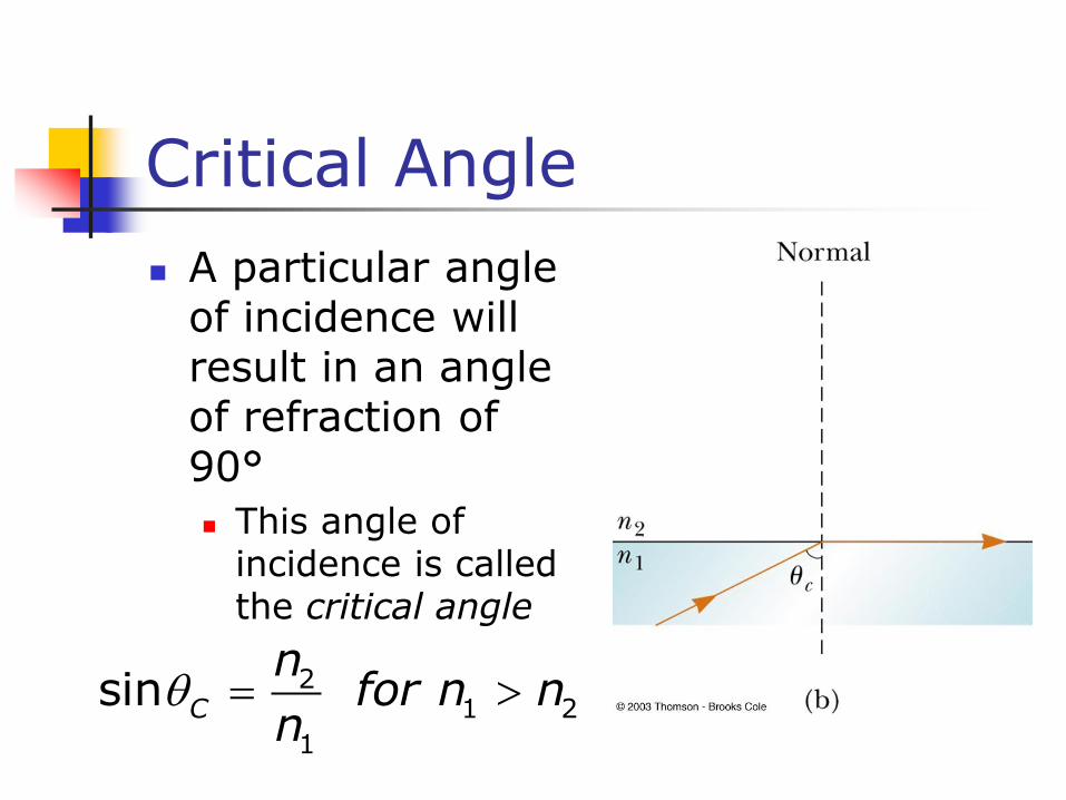
Critical Angle
A particular angle of incidence will result in an angle of refraction of 90°
This angle of incidence is called the critical angle
21 2
1
sin C
nfor n n
n
Critical Angle, cont
For angles of incidence greater than the critical angle, the beam is entirely reflected at the boundary
This ray obeys the Law of Reflection at the boundary
Total internal reflection occurs only when light attempts to move from a medium of higher index of refraction to a medium of lower index of refraction
Fiber Optics
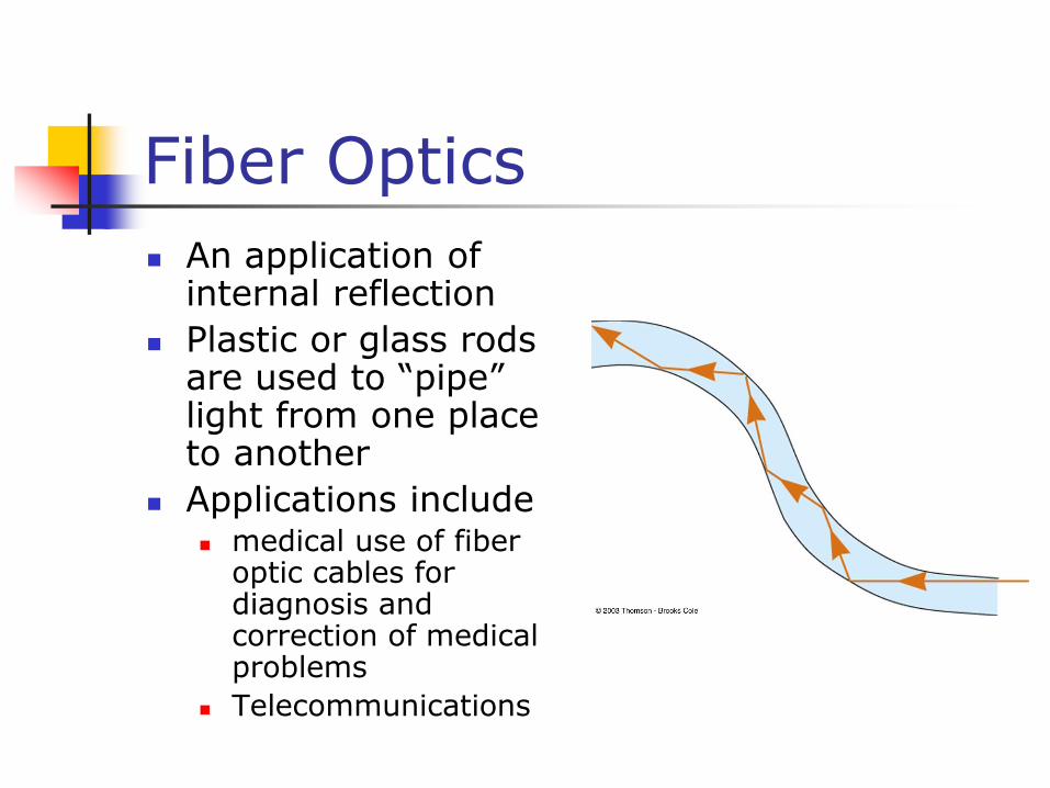
An application of internal reflection
Plastic or glass rods are used to “pipe” light from one place to another
Applications include medical use of fiber
optic cables for diagnosis and correction of medical problems
Telecommunications
Thin Lenses
A thin lens consists of a piece of glass or plastic, ground so that each of its two refracting surfaces is a segment of either a sphere or a plane
Lenses are commonly used to form images by refraction in optical instruments
Thin Lens Shapes
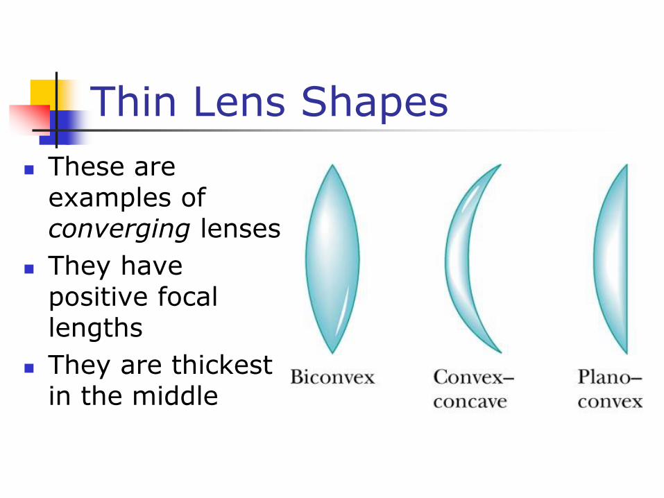
These are examples of converging lenses
They have positive focal lengths
They are thickest in the middle
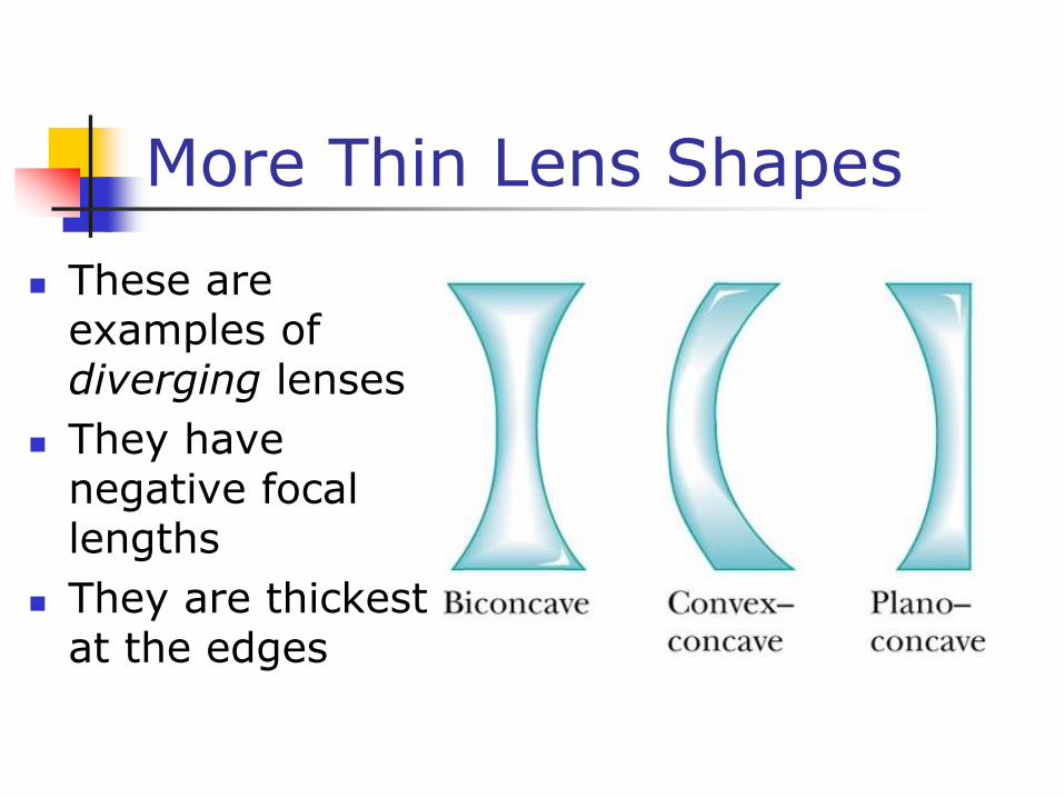
More Thin Lens Shapes
These are examples of diverging lenses
They have negative focal lengths
They are thickest at the edges
Focal Length of Lenses
The focal length, ƒ, is the image distance that corresponds to an infinite object distance This is the same as for mirrors
A thin lens has two focal points, corresponding to parallel rays from the left and from the right A thin lens is one in which the distance
between the surface of the lens and the center of the lens is negligible
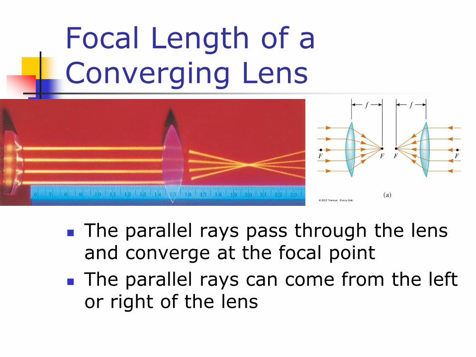
Focal Length of a Converging Lens
The parallel rays pass through the lens and converge at the focal point
The parallel rays can come from the left or right of the lens
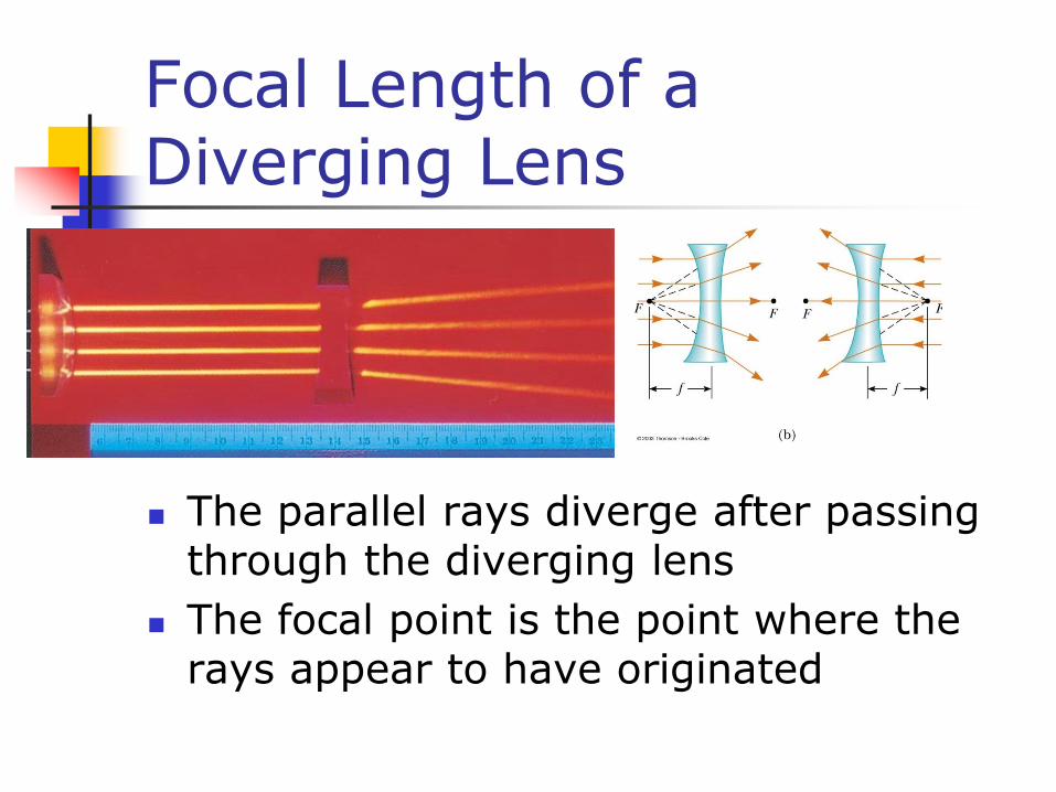
Focal Length of a Diverging Lens
The parallel rays diverge after passing through the diverging lens
The focal point is the point where the rays appear to have originated
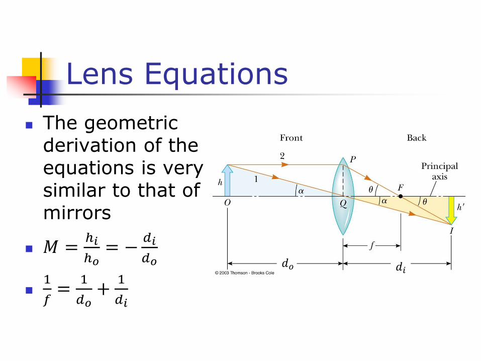
Lens Equations
The geometric derivation of the equations is very similar to that of mirrors
𝑀 =ℎ𝑖
ℎ𝑜= −
𝑑𝑖
𝑑𝑜
1
𝑓=
1
𝑑𝑜+
1
𝑑𝑖
𝑑𝑜 𝑑𝑖
Lens Equations
The equations can be used for both converging and diverging lenses
A converging lens has a positive focal length
A diverging lens has a negative focal length
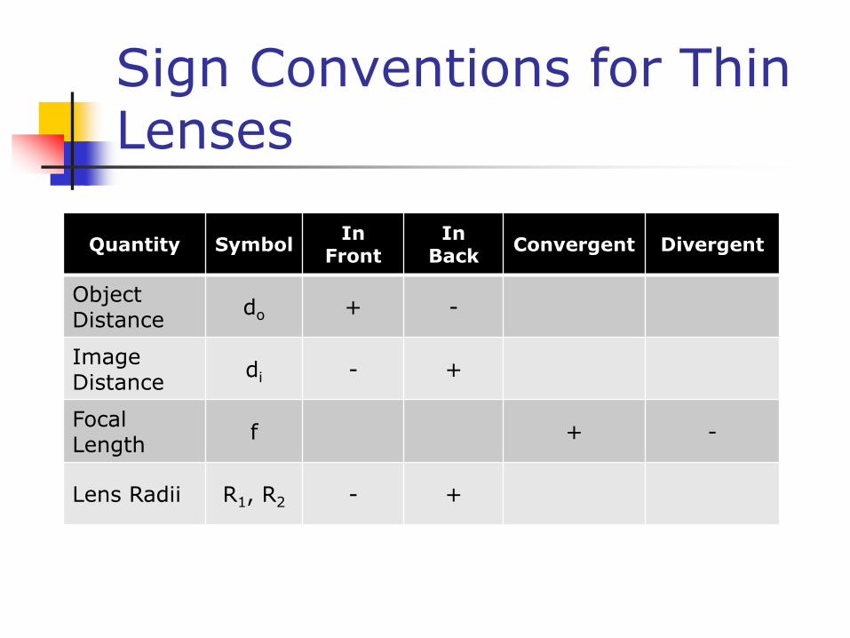
Sign Conventions for Thin Lenses
Quantity SymbolInFront
InBack
Convergent Divergent
Object Distance
do + -
Image Distance
di - +
Focal Length
f + -
Lens Radii R1, R2 - +
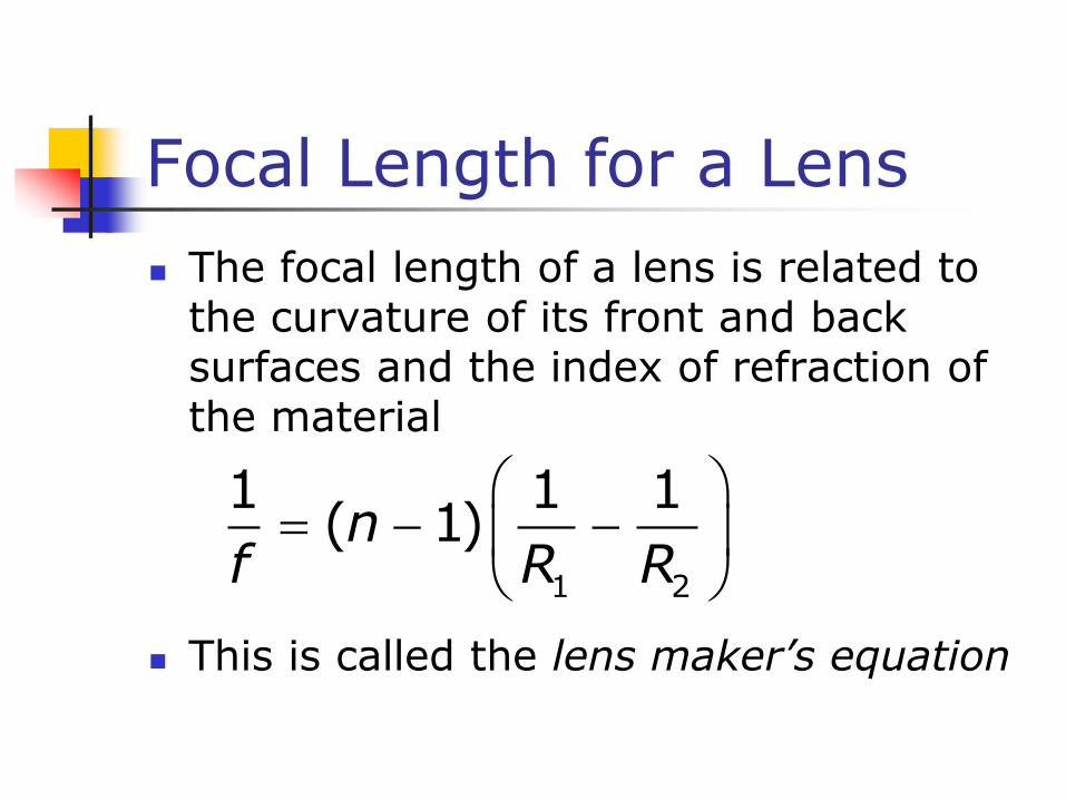
Focal Length for a Lens
The focal length of a lens is related to the curvature of its front and back surfaces and the index of refraction of the material
This is called the lens maker’s equation
1 2
1 1 1( 1)n
f R R
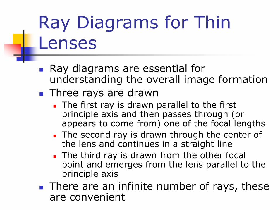
Ray Diagrams for Thin Lenses
Ray diagrams are essential for understanding the overall image formation
Three rays are drawn The first ray is drawn parallel to the first
principle axis and then passes through (or appears to come from) one of the focal lengths
The second ray is drawn through the center of the lens and continues in a straight line
The third ray is drawn from the other focal point and emerges from the lens parallel to the principle axis
There are an infinite number of rays, these are convenient
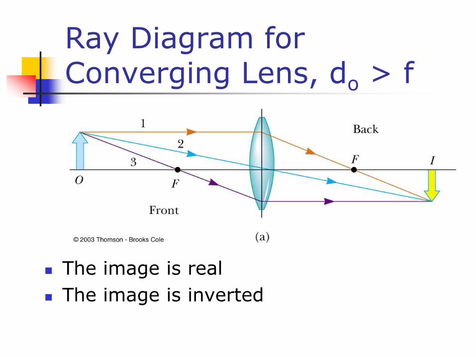
Ray Diagram for Converging Lens, do > f
The image is real
The image is inverted

Ray Diagram for Converging Lens, do < f
The image is virtual
The image is upright
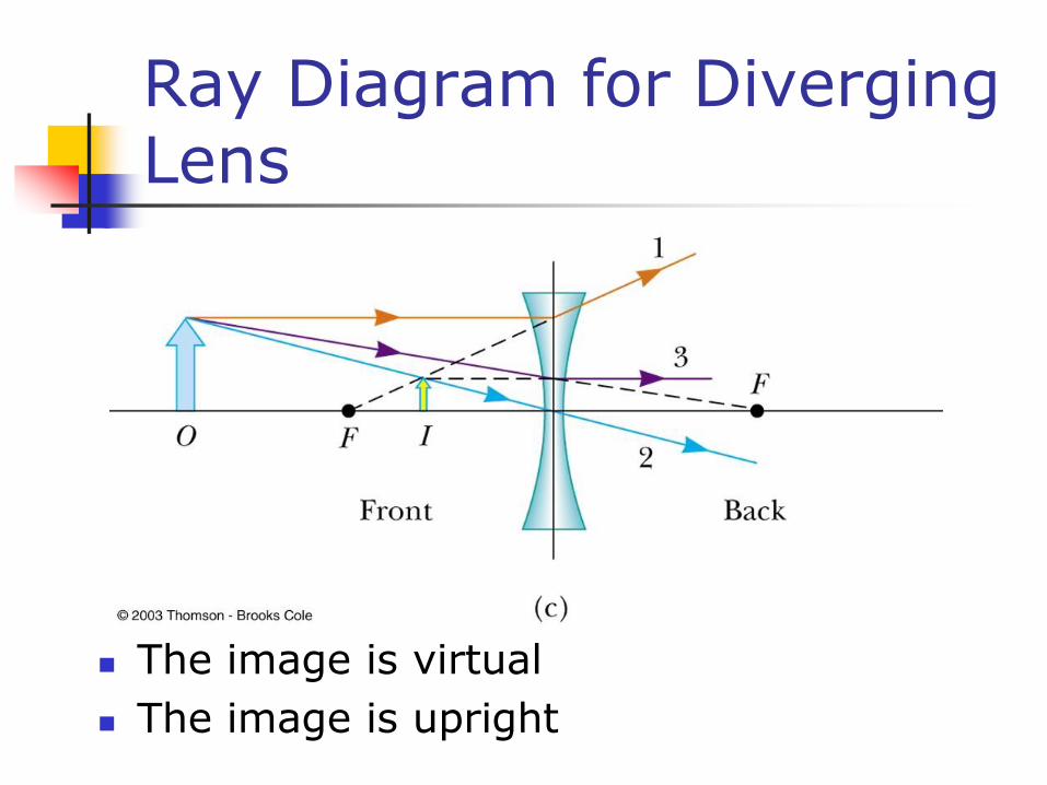
Ray Diagram for Diverging Lens
The image is virtual
The image is upright
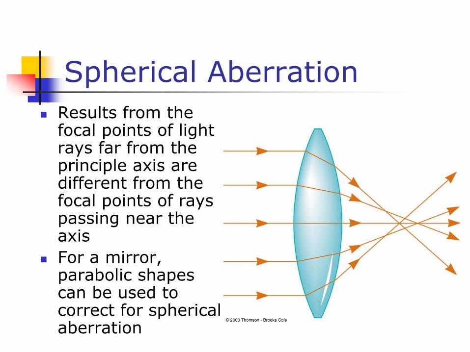
Spherical Aberration
Results from the focal points of light rays far from the principle axis are different from the focal points of rays passing near the axis
For a mirror, parabolic shapes can be used to correct for spherical aberration
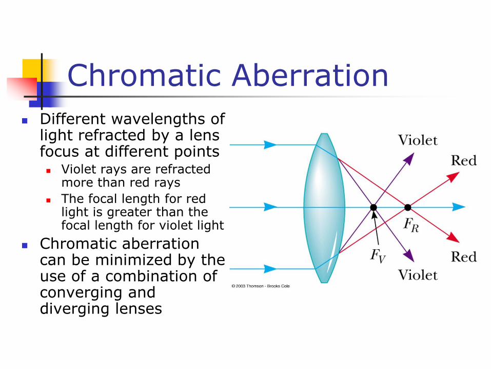
Chromatic Aberration
Different wavelengths of light refracted by a lens focus at different points Violet rays are refracted
more than red rays
The focal length for red light is greater than the focal length for violet light
Chromatic aberration can be minimized by the use of a combination of converging and diverging lenses
C’est Fini