Embed Size (px)
Citation preview
1
Front Page
Refrigerated Air DryersVF SeriesNon-Cycling10 - 2,000 scfm
DHT SeriesHigh Inlet Temperature20 - 125 scfm
2
Since 1994, Aircel has been
delivering quality, industry
leading compressed air dryers
and accessories for production
lines and facilities all over the
world.
Our precise engineering
and designs provide reliable
products that will protect your
operations for years to come.
Based in Maryville, Tennessee,
Aircel is a multi-industry
manufacturing leader. Aircel’s
highly-specialized, engineered
products and technologies
are powering facilities all over
the world. Our products serve
industries such as textile, food
and beverage, automotive,
production, PET market,
breathing air, pneumatic
instrumentation, and more.
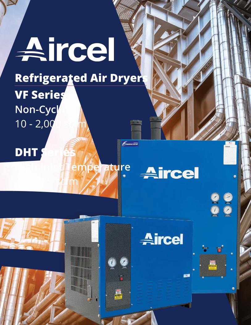
VF Series Non-CyclingRefrigerated Air Dryer | 10 - 2,000 scfm
The Aircel VF Series (10 - 2,000 scfm) offers the highest efficiencies at varying flow conditions in a lightweight, compact design. No other dryer in the industry can offer the efficiency ratings achieved by the VF Series dryers in variable flow operation. VF Series dryers are built with the Variable Flow heat exchanger, which allows for desired dew point performance regardless of flow variations. Typically, other dryers with mechanical moisture separators lose performance as compressed airflow velocity increases or decreases substantially around the nominal design point.
The VF Series high efficiency heat exchanger utilizes a three-step process to thoroughly remove condensed moisture from the chilled, compressed air. This process provides separation efficiency in excess of 99% throughout the entire flow range. Our VF non-cycling range is focused on reliable, constant dew point performance in all flow conditions.
With its excellent heat transfer coefficients and low-pressure drop, these dryers will outperform the competition in protecting your compressed air system, machinery, and tools; and will improve your manufacturing processes.
3
DrainValve
Air or WaterCooled
Condenser
AirCompressor
DrainValve
Dry Airto Plant
DrainValve
VF Series
After Filter
Pre-Filter
Wet Receiver(optional)
Dry Receiver(optional)
Separator
DrainValve
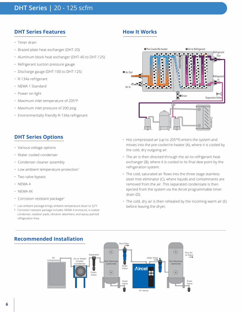
Recommended Installation
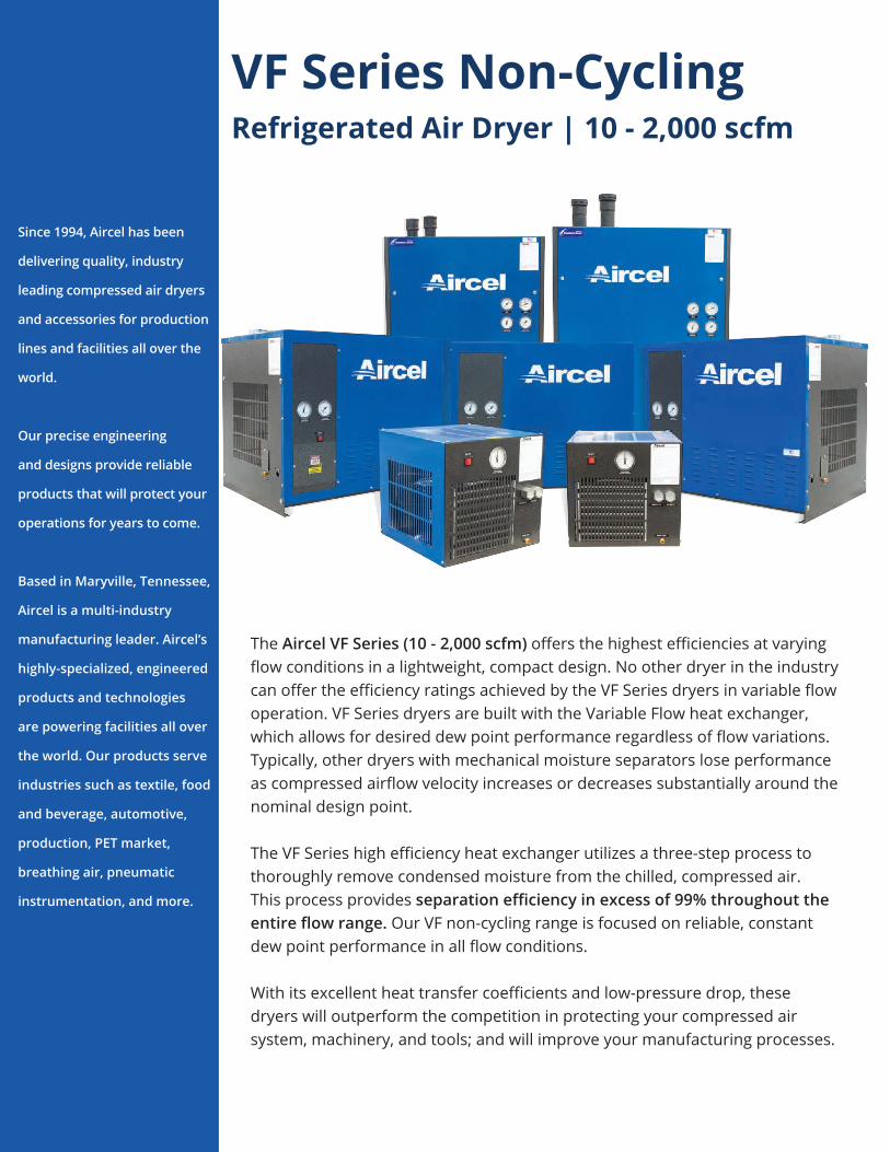
• Saturated, compressed air enters the system and moves into the pre-cooler/re-heater (A), where it is pre-cooled by the cold outgoing air.
• The air is then directed through the air-to-refrigerant heat exchanger (B), where it is cooled to 38°F by the refrigeration system.
• The cold, saturated air flows into the three-stage separator (C), where liquids are removed from the air. This separated condensate is then ejected from the system via the Aircel condensate drain (D).
• The cold, dry air is then reheated by the incoming warm air (E) before leaving the dryer.
• Timer drain (VF-10 to VF-600)
• Zero air loss drain (VF-800 to VF-2,000)
• Refrigerant suction pressure gauge standard
• Discharge gauge (VF-200 to VF-2,000)
• Inlet pressure gauge (VF-400 to VF-2,000)
• Inlet temperature gauge (VF-400 to VF-2,000)
• Internal, high efficiency separator (VF-10 to VF-600)
• External, high efficiency separator (VF-800 to VF-2,000)
• R-134a refrigerant (VF-10 to VF-800)
• R-404a refrigerant (VF-1,000 to VF-2,000)
• NEMA 1 standard
• NEMA 4 standard (VF-1,6000 to VF-2,000)
• Various voltage options
• Water cooled condenser
• Condenser cleaner assembly
• Low ambient temperature protection1
• Two valve bypass
• NEMA 4
• NEMA 4X
• Corrosion resistant package2
To protect your dryer investment, we recommend that you install a high performance pre-filter directly in front of your refrigerated air dryer. By doing this, you will prevent insulating oil and dirt build-up in the heat exchanger and ensure optimal performance and reliability of the dryer throughout its lifetime.
How It Works
Refrigerant Inlet
Air-to-RefrigerantHeat Exchanger
Air Inlet
Pre-Cooler /Re-Heater
Separator
Air Outlet
Air-to-Air Heat Exchanger
Stainless Steel Mist Eliminator
Refrigerant Oulet
A
D
BC
¹ Low ambient package brings ambient temperature down to 32°F ² Corrosion resistant package includes: NEMA 4 enclosure, e-coated
condenser, isolation pads, vibration absorbers, and epoxy painted refrigeration lines
VF Series Features
VF Series Options
Recommended Filtration
10 - 2,000 scfm | VF Series
4
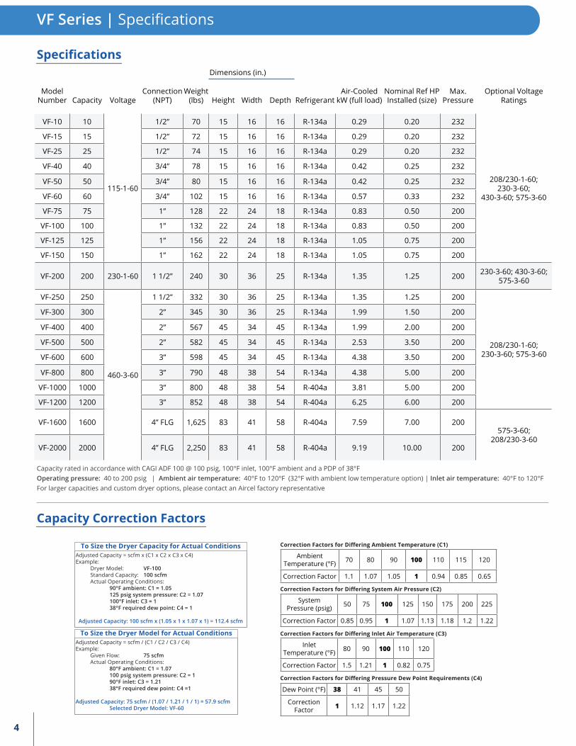
VF Series | Specifications
Dew Point (°F) 38 41 45 50
Correction Factor 1 1.12 1.17 1.22
Correction Factors for Differing Pressure Dew Point Requirements (C4)
Inlet Temperature (°F) 80 90 100 110 120
Correction Factor 1.5 1.21 1 0.82 0.75
Correction Factors for Differing Inlet Air Temperature (C3)
System Pressure (psig) 50 75 100 125 150 175 200 225
Correction Factor 0.85 0.95 1 1.07 1.13 1.18 1.2 1.22
Correction Factors for Differing System Air Pressure (C2)
Dimensions (in.)
Model Number Capacity Voltage
Connection (NPT)
Weight (lbs) Height Width Depth Refrigerant
Air-Cooled kW (full load)
Nominal Ref HP Installed (size)
Max. Pressure
Optional Voltage Ratings
VF-10 10
115-1-60
1/2” 70 15 16 16 R-134a 0.29 0.20 232
208/230-1-60; 230-3-60;
430-3-60; 575-3-60
VF-15 15 1/2” 72 15 16 16 R-134a 0.29 0.20 232
VF-25 25 1/2” 74 15 16 16 R-134a 0.29 0.20 232
VF-40 40 3/4” 78 15 16 16 R-134a 0.42 0.25 232
VF-50 50 3/4” 80 15 16 16 R-134a 0.42 0.25 232
VF-60 60 3/4” 102 15 16 16 R-134a 0.57 0.33 232
VF-75 75 1” 128 22 24 18 R-134a 0.83 0.50 200
VF-100 100 1” 132 22 24 18 R-134a 0.83 0.50 200
VF-125 125 1” 156 22 24 18 R-134a 1.05 0.75 200
VF-150 150 1” 162 22 24 18 R-134a 1.05 0.75 200
VF-200 200 230-1-60 1 1/2” 240 30 36 25 R-134a 1.35 1.25 200 230-3-60; 430-3-60; 575-3-60
VF-250 250
460-3-60
1 1/2” 332 30 36 25 R-134a 1.35 1.25 200
208/230-1-60;230-3-60; 575-3-60
VF-300 300 2” 345 30 36 25 R-134a 1.99 1.50 200
VF-400 400 2” 567 45 34 45 R-134a 1.99 2.00 200
VF-500 500 2” 582 45 34 45 R-134a 2.53 3.50 200
VF-600 600 3” 598 45 34 45 R-134a 4.38 3.50 200
VF-800 800 3” 790 48 38 54 R-134a 4.38 5.00 200
VF-1000 1000 3” 800 48 38 54 R-404a 3.81 5.00 200
VF-1200 1200 3” 852 48 38 54 R-404a 6.25 6.00 200
VF-1600 1600 4” FLG 1,625 83 41 58 R-404a 7.59 7.00 200575-3-60;
208/230-3-60VF-2000 2000 4” FLG 2,250 83 41 58 R-404a 9.19 10.00 200
Capacity Correction Factors
Specifications
Ambient Temperature (°F) 70 80 90 100 110 115 120
Correction Factor 1.1 1.07 1.05 1 0.94 0.85 0.65
Correction Factors for Differing Ambient Temperature (C1)To Size the Dryer Capacity for Actual ConditionsAdjusted Capacity = scfm x (C1 x C2 x C3 x C4)Example: Dryer Model: VF-100 Standard Capacity: 100 scfm Actual Operating Conditions: 90°F ambient: C1 = 1.05 125 psig system pressure: C2 = 1.07 100°F inlet: C3 = 1 38°F required dew point: C4 = 1
Adjusted Capacity: 100 scfm x (1.05 x 1 x 1.07 x 1) = 112.4 scfm
To Size the Dryer Model for Actual ConditionsAdjusted Capacity = scfm / (C1 / C2 / C3 / C4)Example: Given Flow: 75 scfm Actual Operating Conditions: 80°F ambient: C1 = 1.07 100 psig system pressure: C2 = 1 90°F inlet: C3 = 1.21 38°F required dew point: C4 =1 Adjusted Capacity: 75 scfm / (1.07 / 1.21 / 1 / 1) = 57.9 scfm Selected Dryer Model: VF-60
Capacity rated in accordance with CAGI ADF 100 @ 100 psig, 100°F inlet, 100°F ambient and a PDP of 38°FOperating pressure: 40 to 200 psig | Ambient air temperature: 40°F to 120°F (32°F with ambient low temperature option) | Inlet air temperature: 40°F to 120°FFor larger capacities and custom dryer options, please contact an Aircel factory representative
5
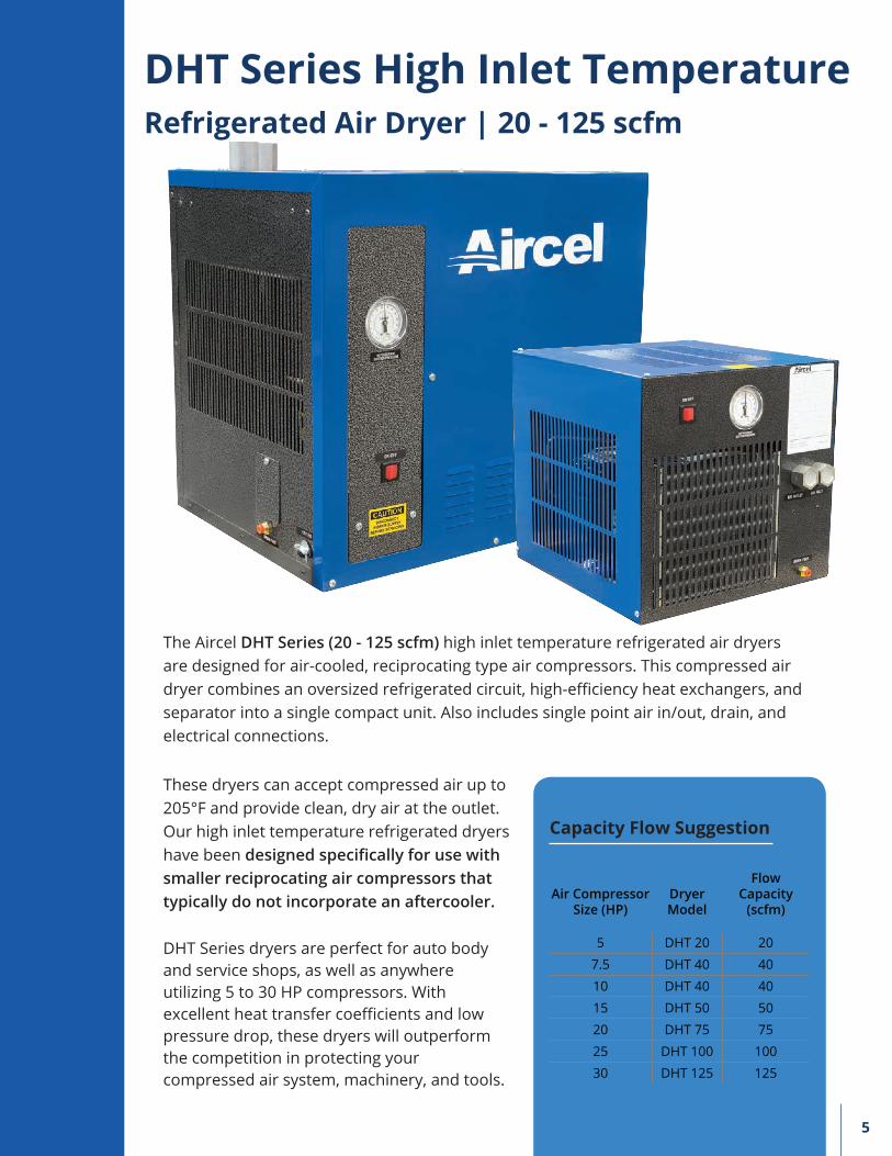
DHT Series High Inlet TemperatureRefrigerated Air Dryer | 20 - 125 scfm
The Aircel DHT Series (20 - 125 scfm) high inlet temperature refrigerated air dryers are designed for air-cooled, reciprocating type air compressors. This compressed air dryer combines an oversized refrigerated circuit, high-efficiency heat exchangers, and separator into a single compact unit. Also includes single point air in/out, drain, and electrical connections.
Air Compressor Size (HP)
Dryer Model
Flow Capacity
(scfm)
5 DHT 20 20
7.5 DHT 40 40
10 DHT 40 40
15 DHT 50 50
20 DHT 75 75
25 DHT 100 100
30 DHT 125 125
Capacity Flow Suggestion
These dryers can accept compressed air up to 205°F and provide clean, dry air at the outlet. Our high inlet temperature refrigerated dryers have been designed specifically for use with smaller reciprocating air compressors that typically do not incorporate an aftercooler.
DHT Series dryers are perfect for auto body and service shops, as well as anywhere utilizing 5 to 30 HP compressors. With excellent heat transfer coefficients and low pressure drop, these dryers will outperform the competition in protecting your compressed air system, machinery, and tools.
6
• Hot compressed air (up to 205°F) enters the system and moves into the pre-cooler/re-heater (A), where it is cooled by the cold, dry outgoing air.
• The air is then directed through the air-to-refrigerant heat exchanger (B), where it is cooled to its final dew point by the refrigeration system.
• The cold, saturated air flows into the three stage stainless steel mist eliminator (C), where liquids and contaminants are removed from the air. This separated condensate is then ejected from the system via the Aircel programmable timer drain (D).
• The cold, dry air is then reheated by the incoming warm air (E) before leaving the dryer.
A B
D
E
Condenser
Compressor
Expansion Valve
Separator
Pre-Cooler/Re-heater Air to Refrigerant
Drain
RefrigerantOut
RefrigerantIn
Air In
Air Out
C
DHT Series | 20 - 125 scfm
DrainValve
Air or WaterCooled
Condenser
AirCompressor
DrainValve
Dry Airto Plant
DrainValve
VF Series
After Filter
Pre-Filter
Wet Receiver(optional)
Dry Receiver(optional)
Separator
DrainValve
Recommended Installation
• Timer drain
• Brazed plate heat exchanger (DHT-20)
• Aluminum block heat exchanger (DHT-40 to DHT-125)
• Refrigerant suction pressure gauge
• Discharge gauge (DHT-100 to DHT-125)
• R-134a refrigerant
• NEMA 1 Standard
• Power on-light
• Maximum inlet temperature of 205°F
• Maximum inlet pressure of 200 psig
• Environmentally friendly R-134a refrigerant
• Various voltage options
• Water cooled condenser
• Condenser cleaner assembly
• Low ambient temperature protection1
• Two valve bypass
• NEMA 4
• NEMA 4X
• Corrosion resistant package2
How It Works
¹ Low ambient package brings ambient temperature down to 32°F ² Corrosion resistant package includes: NEMA 4 enclosure, e-coated
condenser, isolation pads, vibration absorbers, and epoxy painted refrigeration lines
DHT Series Features
DHT Series Options
7
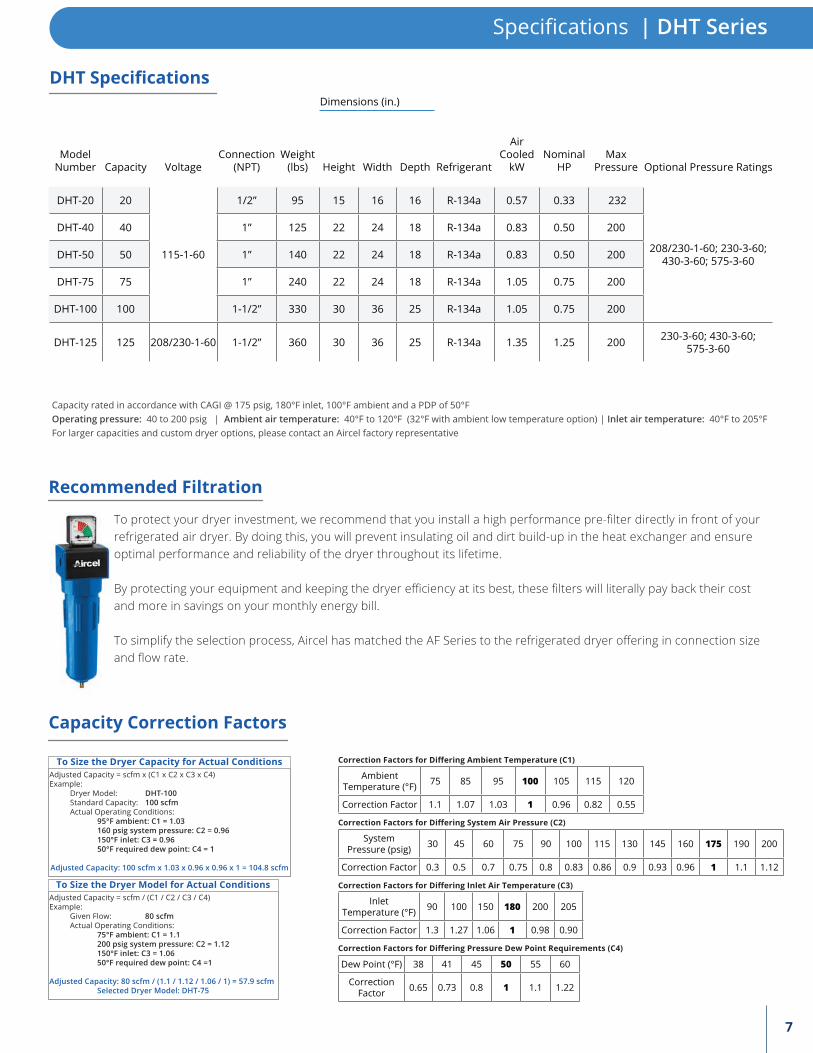
Dimensions (in.)
ModelNumber Capacity Voltage
Connection (NPT)
Weight (lbs) Height Width Depth Refrigerant
Air Cooled
kWNominal
HPMax
Pressure Optional Pressure Ratings
DHT-20 20
115-1-60
1/2” 95 15 16 16 R-134a 0.57 0.33 232
208/230-1-60; 230-3-60; 430-3-60; 575-3-60
DHT-40 40 1” 125 22 24 18 R-134a 0.83 0.50 200
DHT-50 50 1” 140 22 24 18 R-134a 0.83 0.50 200
DHT-75 75 1” 240 22 24 18 R-134a 1.05 0.75 200
DHT-100 100 1-1/2” 330 30 36 25 R-134a 1.05 0.75 200
DHT-125 125 208/230-1-60 1-1/2” 360 30 36 25 R-134a 1.35 1.25 200 230-3-60; 430-3-60; 575-3-60
DHT Specifications
Specifications | DHT Series
Capacity rated in accordance with CAGI @ 175 psig, 180°F inlet, 100°F ambient and a PDP of 50°FOperating pressure: 40 to 200 psig | Ambient air temperature: 40°F to 120°F (32°F with ambient low temperature option) | Inlet air temperature: 40°F to 205°FFor larger capacities and custom dryer options, please contact an Aircel factory representative
Dew Point (°F) 38 41 45 50 55 60
Correction Factor 0.65 0.73 0.8 1 1.1 1.22
Correction Factors for Differing Pressure Dew Point Requirements (C4)
Inlet Temperature (°F) 90 100 150 180 200 205
Correction Factor 1.3 1.27 1.06 1 0.98 0.90
Correction Factors for Differing Inlet Air Temperature (C3)
System Pressure (psig) 30 45 60 75 90 100 115 130 145 160 175 190 200
Correction Factor 0.3 0.5 0.7 0.75 0.8 0.83 0.86 0.9 0.93 0.96 1 1.1 1.12
Correction Factors for Differing System Air Pressure (C2)
Capacity Correction Factors
Ambient Temperature (°F) 75 85 95 100 105 115 120
Correction Factor 1.1 1.07 1.03 1 0.96 0.82 0.55
Correction Factors for Differing Ambient Temperature (C1)To Size the Dryer Capacity for Actual ConditionsAdjusted Capacity = scfm x (C1 x C2 x C3 x C4)Example: Dryer Model: DHT-100 Standard Capacity: 100 scfm Actual Operating Conditions: 95°F ambient: C1 = 1.03 160 psig system pressure: C2 = 0.96 150°F inlet: C3 = 0.96 50°F required dew point: C4 = 1
Adjusted Capacity: 100 scfm x 1.03 x 0.96 x 0.96 x 1 = 104.8 scfm
To Size the Dryer Model for Actual ConditionsAdjusted Capacity = scfm / (C1 / C2 / C3 / C4)Example: Given Flow: 80 scfm Actual Operating Conditions: 75°F ambient: C1 = 1.1 200 psig system pressure: C2 = 1.12 150°F inlet: C3 = 1.06 50°F required dew point: C4 =1 Adjusted Capacity: 80 scfm / (1.1 / 1.12 / 1.06 / 1) = 57.9 scfm Selected Dryer Model: DHT-75
To protect your dryer investment, we recommend that you install a high performance pre-filter directly in front of your refrigerated air dryer. By doing this, you will prevent insulating oil and dirt build-up in the heat exchanger and ensure optimal performance and reliability of the dryer throughout its lifetime.
By protecting your equipment and keeping the dryer efficiency at its best, these filters will literally pay back their cost and more in savings on your monthly energy bill.
To simplify the selection process, Aircel has matched the AF Series to the refrigerated dryer offering in connection size and flow rate.
Recommended Filtration

8
323 Crisp Circle · Maryville, TN 37801 | office: 865-681-7066 | [email protected]
Please visit us at airceldryers.com
Aircel, LLC. reserves the right to update or change specifications at any time without prior notice.
MADE INTHE USA