Embed Size (px)
Citation preview
Part 2 - Refrigeration System Components
Refrigeration Manual
© 1967 Emerson Climate Technologies, Inc.All rights reserved.
This is the second of a series of publications comprising the Emerson Climate Technologies, Inc. Refrigeration Manual, and follows Part 1, “Fundamentals of Refrigeration.”
The information included on refrigeration components is general in nature and is intended only to give a brief description of their operation. Detailed information as to specifi c products is available from manufacturers of components and accessories.
© 1967 Emerson Climate Technologies, Inc.All rights reserved.
1
Part IIREFRIGERATION SYSTEM COMPONENTS
Section 4. COMPRESSORS Reciprocating Compressors ............................. 4-1 Open Type Compressors .................................. 4-2 Accessible-Hermetic Motor-Compressors ........ 4-2 Welded Hermetic Motor-Compressors ............. 4-2 Compressor Speed........................................... 4-2 Basic Compressor Operation ........................... 4-4 Suction and Discharge Valves .......................... 4-4 Compressor Displacement ............................... 4-4 Clearance Volume ............................................ 4-4 Lubrication ........................................................ 4-5 Dry Air Holding Charge ..................................... 4-6 Compressor Cooling ......................................... 4-6 Compressor Capacity ....................................... 4-6 Two Stage Compressors .................................. 4-6 Compressors with Unloaders ......................... 4-7 Tandem Compressors ...................................... 4-7
Section 5. CONDENSERS
Air Cooled Condensers .................................... 5-1 Water Cooled Condensers ............................... 5-2 Evaporative Condensers .................................. 5-4 Condenser Capacity ......................................... 5-5 Condensing Temperature ................................. 5-5 Non-Condensable Gases ................................. 5-5 Condensing Temperature Difference ................ 5-6
Section 6. EVAPORATORS
Types of Evaporators........................................ 6-1 Blower Coil Construction .................................. 6-1 Pressure Drop and Other Factors in Evaporator Design ................................. 6-2 Evaporator Capacity ......................................... 6-2 Temperature Difference and Dehumidifi cation ........................................ 6-2 Defrosting of Blower Coils ................................ 6-3
Section 7. CONTROL DEVICES, REFRIGERANT
Thermostatic Expansion Valves ....................... 7- 1 Other Types of Expansion Valves ..................... 7- 2 Distributors ....................................................... 7- 2 Capillary Tubes ................................................. 7- 2 Float Valves ...................................................... 7- 8Solenoid Valves ................................................ 7- 8 Crankcase Pressure Regulating Valves ........... 7- 9 Evaporator Pressure Regulating Valve ............. 7- 9 Hot Gas Bypass Valves .................................... 7- 9 Reversing Valves .............................................. 7-10 Check Valves .................................................... 7-10 Manual Shut-Off Valves .................................... 7-11 Compressor Service Valves ............................. 7-11 Schrader Type Valve ........................................ 7-11 Pressure Relief Valves ..................................... 7-12 Fusible Plugs .................................................... 7-12 Water Regulating Valves .................................. 7-12
Section 8. CONTROL DEVICES, ELECTRICAL Control Differential ............................................ 8-1 Line Voltage and Low Voltage Controls ............ 8-1 Low Pressure and High Pressure Controls ...... 8-1 Condenser Fan Cycling Control ....................... 8-2 Thermostats...................................................... 8-2 Oil Pressure Safety Control .............................. 8-2 Time Clocks ...................................................... 8-2Relays............................................................... 8-3 Time Delay Relay ............................................. 8-3 Transformers .................................................... 8-3
© 1967 Emerson Climate Technologies, Inc.All rights reserved.
Section 9. MOTORS
Motor Temperature ........................................... 9-1 Open Type Motors and Belt Drives ................... 9-1 Hermetic Motors ............................................... 9-2 Nameplate Amperage ....................................... 9-2 Voltage and Frequency..................................... 9-3 Three Phase Motors ......................................... 9-3 Single Phase Motors ........................................ 9-3 Split Phase Motors ........................................... 9-3 Capacitor Start-Induction Run Motors (CSIR) ....................................................... 9-4 Capacitor Start-Capacitor Run Motors (CSR) ........................................................ 9-4 Permanent Split Capacitor Motors (PSC) ......... 9-5 Dual Voltage Motors ......................................... 9-5 Two Phase Motors ............................................ 9-6
Section 10. STARTING EQUIPMENT AND MOTOR PROTECTORS
Contactors and Starters.................................... 10-1 Capacitors ........................................................ 10-1 Start Capacitors ................................................ 10-2Run Capacitors ................................................. 10-2Reduced Voltage Starting ................................. 10-3
Motor Protection ............................................... 10-8 Internal Inherent Line Break Protector.............. 10-8 External Inherent Protector............................... 10-9Internal Thermostats ......................................... 10-9 External Thermostats ....................................... 10-9Current Sensitive Protectors............................. 10-9Thermotector .................................................... 10-9Solid State Protectors ....................................... 10-9Fuses and Circuit Breakers .............................. 10-9 Effect of Unbalanced Voltage and Current on Three Phase Motor Protection ............. 10-10
Section 11. ACCESSORIES
Receivers.......................................................... 11-1 Heat Exchangers .............................................. 11-1 Suction Accumulators ....................................... 11-1 Oil Separators................................................... 11-2 Dehydrators ...................................................... 11-2 Suction Line Filters ........................................... 11-2 Vibration Eliminators ......................................... 11-2 Strainers ........................................................... 11-3 Sight Glass and Moisture Indicators ................. 11-3 Discharge Muffl ers............................................ 11-3 Crankcase Heaters ........................................... 11-3Refrigeration Gauges ....................................... 11-4
© 1967 Emerson Climate Technologies, Inc.All rights reserved.
SECTION 4 COMPRESSORS
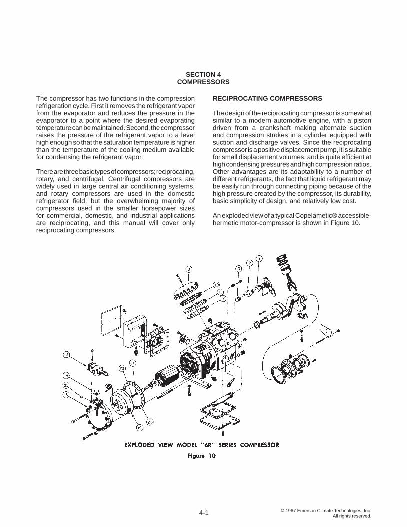
RECIPROCATING COMPRESSORS The design of the reciprocating compressor is somewhat similar to a modern automotive engine, with a piston driven from a crankshaft making alternate suction and compression strokes in a cylinder equipped with suction and discharge valves. Since the reciprocating compressor is a positive displacement pump, it is suitable for small displacement volumes, and is quite effi cient at high condensing pressures and high compression ratios. Other advantages are its adaptability to a number of different refrigerants, the fact that liquid refrigerant may be easily run through connecting piping because of the high pressure created by the compressor, its durability, basic simplicity of design, and relatively low cost.
An exploded view of a typical Copelametic® accessible-hermetic motor-compressor is shown in Figure 10.
The compressor has two functions in the compression refrigeration cycle. First it removes the refrigerant vapor from the evaporator and reduces the pressure in the evaporator to a point where the desired evaporating temperature can be maintained. Second, the compressor raises the pressure of the refrigerant vapor to a level high enough so that the saturation temperature is higher than the temperature of the cooling medium available for condensing the refrigerant vapor.
There are three basic types of compressors; reciprocating, rotary, and centrifugal. Centrifugal compressors are widely used in large central air conditioning systems, and rotary compressors are used in the domestic refrigerator fi eld, but the overwhelming majority of compressors used in the smaller horsepower sizes for commercial, domestic, and industrial applications are reciprocating, and this manual will cover only reciprocating compressors.
4-1
© 1967 Emerson Climate Technologies, Inc.All rights reserved.
OPEN TYPE COMPRESSORS
Early models of refrigeration compressors were of the so-called open type, with the pistons and cylinders sealed within a crankcase, and a crankshaft extending through the body for an external power source. A shaft seal around the crankshaft prevented the loss of refrigerant and oil from the body.
Although at one time open type compressors were widely used, they have many inherent disadvantages such as greater weight, higher cost, larger size, vulnerability to seal failures, diffi cult shaft alignment, excessive noise, and short life of belts or direct drive components. As a result, the open type compressor has been largely replaced with the accessible-hermetic and hermetic type motor-compressor in most applications, and the use of open type compressors continues to decline except for specialized applications such as automobile air conditioning.
ACCESSIBLE-HERMETIC MOTOR-COMPRESSORS
The accessible-hermetic motor-compressor design was pioneered by Emerson Climate Technologies, Inc. and is widely used in the popular Copelametic® models. The compressor is driven by an electric motor mounted directly on the compressor crankshaft, with both the motor and the compressor working parts hermetically sealed within a common enclosure. The troublesome shaft seal is eliminated, motors can be sized specifi cally for the load to be handled, and the resulting design is compact, economical, effi cient, and basically maintenance free.
Removable heads, stator covers, bottom plates, and housing covers allow access for easy fi eld repairs in the event of compressor damage.
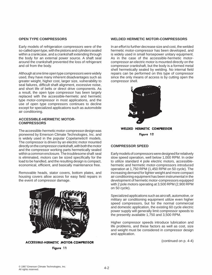
WELDED HERMETIC MOTOR-COMPRESSORS
In an effort to further decrease size and cost, the welded hermetic motor-compressor has been developed, and is widely used in small horsepower unitary equipment. As in the case of the accessible-hermetic motor-compressor an electric motor is mounted directly on the compressor crankshaft, but the body is a formed metal shell hermetically sealed by welding. No internal fi eld repairs can be performed on this type of compressor since the only means of access is by cutting open the compressor shell.
COMPRESSOR SPEED Early models of compressors were designed for relatively slow speed operation, well below 1,000 RPM. In order to utilize standard 4 pole electric motors, accessible-hermetic and hermetic motor-compressors introduced operation at 1,750 RPM (1,450 RPM on 50 cycle). The increasing demand for lighter weight and more compact air conditioning equipment has been instrumental in the development of hermetic motor-compressors equipped with 2 pole motors operating at 3,500 RPM (2,900 RPM on 50 cycle).
Specialized applications such as aircraft, automotive, or military air conditioning equipment utilize even higher speed compressors, but for the normal commercial and domestic application, the existing 60 cycle electric power supply will generally limit compressor speeds to the presently available 1,750 and 3,500 RPM.
Higher compressor speeds introduce lubrication and life problems, and these factors as well as cost, size and weight must be considered in compressor design and application.
4-2
(continued on p. 4-4)
© 1967 Emerson Climate Technologies, Inc.All rights reserved.4-3
CR
OSS
-SEC
TIO
NA
L VI
EW O
F C
OPE
LAM
ETIC
® M
OTO
R-C
OM
PRES
SOR
© 1967 Emerson Climate Technologies, Inc.All rights reserved.
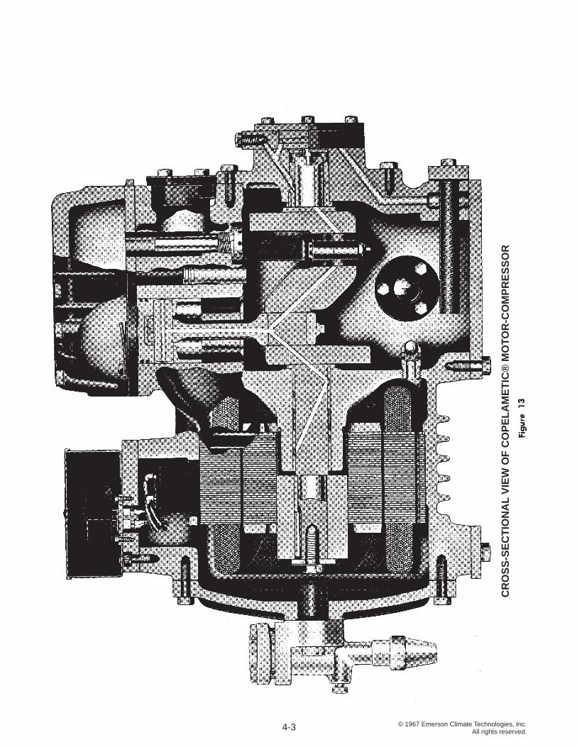
BASIC COMPRESSOR OPERATION
A cross-sectional view of a typical Copelametic® motor-compressor is shown in Figure 13. Following is a brief description of its operation.
As the piston moves downward on the suction stroke, pressure is reduced in the cylinder. When the pressure falls below that in the compressor suction line, the pressure differential causes the suction valves to open and forces the refrigerant vapor to fl ow into the cylinder.
As the piston reaches the bottom of its stroke and starts upward on the compression stroke, pressure is developed in the cylinder, forcing the suction valves closed. The pressure in the cylinder continues to rise as the piston moves upward, compressing the vapor trapped in the cylinder. When the pressure in the cylinder exceeds the pressure existing in the compressor discharge line, the discharge valves are forced open, and the compressed gas fl ows into the discharge line and on into the condenser.
When the piston starts downward, the reduction in pressure allows the discharge valves to close because of the higher pressure in the condenser and discharge line, and the cycle is repeated.
For every revolution of the crankshaft, there is both a suction and compression stroke of each piston, so in 1,750 RPM motor-compressors there are 1,750 complete compression and suction cycles in each cylinder each minute, and in 3,500 RPM motor-compressors, 3,500 complete cycles each minute.
SUCTION AND DISCHARGE VALVES
Since the parts of the compressor most apt to require service are the suction and discharge valves, on Copelametic® compressors these valves are mounted on a valve plate which can be removed for easy service or replacement. A typical valve plate is shown in Figure 10, part number 11.
Most reciprocating compressor valves are of the reed type, and must seat properly to avoid leakage. The least bit of foreign material or corrosion under the valve will cause leakage and the utmost care must be used in protecting the compressor against contamination.
COMPRESSOR DISPLACEMENT
The displacement of a reciprocating compressor is the volume displaced by the pistons. Emerson Climate
Technologies, Inc. publishes the displacement of a compressor in terms of cubic feet per hour, but some manufacturers rate their compressors in terms of cubic inch displacement per revolution, or in cubic feet per minute. For comparative purposes, compressor displacement may be calculated by the following formulas:
DISPLACEMENT
CFM = x D² x L x RPM x N 4 x 1728
CFH = x D² x L x RPM x N x 60 4 x 1728
Cu. In./Rev. = x D² x L x N 4
CONVERSION FACTORS
1750 RPM 3500 RPM CFH = 60 x CFM 60 x CFM CFH = 60.78 x 121.5 x Cu. In./Rev. Cu. In./Rev. CFM = 1.013 x 2.025 x Cu. In./Rev. Cu. In./Rev. Cu. In./Rev. = .01645 x CFH .00823 x CFH CFM = Cubic feet per minute CFH = Cubic feet per hour Cu. In./Rev. = Cubic inch d isp lacement per revolution = 3.1416 D = Cylinder bore, inches L = Length of stroke, inches N = Number of cylinders RPM = Revolutions per minute 1728 = Cubic inches per cubic foot D² = Area of a circle 4
CLEARANCE VOLUME
As mentioned previously, the volumetric effi ciency of a compressor will vary with compressor design. If the valves seat properly, the most important factor affecting compressor effi ciency is clearance volume.
At the completion of the compression stroke, there still remains some clearance space which is essential if the piston is not to hit the valve plate. There is also a great deal more space in the discharge valve ports in the valve plate, since the discharge valves are on top of the valve plate. This residual space which is unswept by the piston at the end of the stroke is termed clearance volume, and remains fi lled with hot, compressed gas at the end of the compression stroke.
4-4
© 1967 Emerson Climate Technologies, Inc.All rights reserved.
When the piston starts down on the suction stroke, the residual high pressure gas expands and its pressure is reduced. No vapor from the suction line can enter the cylinder until the pressure in the cylinder has been reduced below the suction line pressure. Thus, the fi rst part of the suction stroke is actually lost from a capacity standpoint, and as the compression ratio increases, a greater percentage of the suction stroke is occupied by the residual gas.
With high suction pressures, the compression ratio is low and clearance volume is not critical from a capacity standpoint. Additional clearance volume is also helpful in reducing the compressor noise level. Since lower gas velocities through the discharge ports reduce both wear and operating power requirements, on Copeland® brand air conditioning compressors, valve plates are designed with greater clearance volume by increasing the diameter of the discharge ports.
On low temperature applications, it is often necessary to reduce the clearance volume to obtain the desired capacity. Low temperature valve plates having smaller discharge port sizes to reduce the clearance volume are used on low temperature Copelametic® compressors.
LUBRICATION
An adequate supply of oil must be maintained in the crankcase at all times to insure continuous lubrication. The normal oil level should be maintained at or slightly above the center of the sight class.
On all Copelametic® compressors 5 H.P. and larger in size, and on 3 H.P. “NR” models, compressor lubrication is provided by means of a positive displacement oil pump. The pump is mounted on the bearing housing, and is driven from a slot in the crankshaft into which the fl at end of the oil pump drive shaft is fi tted.
Oil is forced through a hole in the crankshaft to the compressor bearings and connecting rods. A spring loaded ball check valve serves as a pressure relief device, allowing oil to bypass directly to the compressor crankcase if the oil pressure rises above its setting.
Since the oil pump intake is connected directly to the compressor crankcase, the oil pump inlet pressure will always be crankcase pressure, and the oil pump outlet pressure will be the sum of crankcase pressure plus oil pump pressure. Therefore, the net oil pump pressure is always the pump outlet pressure minus the crankcase pressure. When the compressor is operating with the suction pressure in a vacuum, the crankcase pressure is negative and must be added to the pump outlet pressure to determine the net oil pump pressure.
A typical compound gauge is calibrated in inches of mercury for vacuum readings, and 2 inches of mercury are approximately equal to 1 psi.
For example: Pump Net Oil Crankcase Outlet Pump Pressure Pressure Pressure 50 psig 90 psig 40 psi 8” vacuum 36 psig 40 psi (equivalent to a reading of minus 4 psig)
In normal operation, the net oil pressure will vary depending on the size of the compressor, the temperature and viscosity of the oil, and the amount of clearance in the compressor bearings. Net oil pressures of 30 to 40 psi are normal, but adequate lubrication will be maintained at pressures down to 10 psi. The bypass valve is set at the factory to prevent the net pump pressure from exceeding 60 psi.
The oil pump may be operated in either direction, the reversing action being accomplished by a friction plate which shifts the inlet and outlet ports. After prolonged operation in one direction, wear, corrosion, varnish formation, or burrs may develop on the reversing plate, and this can prevent the pump from reversing. Therefore, on installations where compressors have been in service for some time, care must be taken to maintain the original phasing of the motor if for any reason the electrical connections are disturbed.
The presence of liquid refrigerant in the crankcase can materially affect the operation of the oil pump. Violent foaming on start up can result in the loss of oil from the crankcase, and a resulting loss of oil pressure until oil returns to the crankcase. If liquid refrigerant or a refrigerant rich mixture of oil and refrigerant is drawn into the oil pump, the resulting fl ash gas may result in large variations and possibly a loss of oil pressure. Crankcase pressure may vary from suction pressure since liquid refrigerant in the crankcase can pressurize the crankcase for short intervals, and the oil pressure safety switch low pressure connection should always be connected to the crankcase.
During a rapid pull-down of the refrigerant evaporating temperature, the amount of refrigerant in solution in the crankcase oil will be reduced, and may cause fl ash gas at the oil pump. During this period the oil pump must pump both the fl ash gas and oil, and as a result the oil pressure may decrease temporarily. This will merely cause the oil pump to bypass less oil, and so long as the oil pressure remains above 9 psi, adequate lubrication
4-5
© 1967 Emerson Climate Technologies, Inc.All rights reserved.
will be maintained. As soon as a stabilized condition is reached, and liquid refrigerant is no longer reaching the pump, the oil pressure will return to normal.
DRY AIR HOLDING CHARGE
All Copeland® brand compressors are thoroughly dehydrated at the factory, and are shipped with a dry air holding charge. The pressure inside a factory processed compressor is a guarantee that the compressor is leak tight, and the interior is absolutely dry. When installed, the compressor must be evacuated to remove the air from the system.
COMPRESSOR COOLING
Air cooled compressors require an adequate fl ow of cooling air over the compressor body to prevent the compressor from overheating. The air fl ow from the fan must be discharged directly on the motor-compressor. Air drawn through a compartment in which the compressor is located usually will not cool the compressor adequately.
Water cooled compressors are provided with a water jacket or wrapped with a copper water coil, and water must be circulated through the cooling circuit when the compressor is in operation.
Refrigerant cooled motor-compressors are designed so that suction gas fl ows around and through the motor for cooling. At evaporating temperatures below 0° F. additional motor cooling by means of air fl ow is necessary since the decreasing density of the refrigerant gas reduces its cooling ability.
COMPRESSOR CAPACITY
Capacity data is available from the manufacturer on each model of compressor for the refrigerants with which the compressor can be used. This data may be in the form of curves or in tabular form, and lists the BTU/hr. capacity at various saturated suction and discharge temperatures.
It is diffi cult to estimate compressor capacities accurately on the basis of displacement and compression ratio because of design differences between different models, but occasionally these factors can be valuable in estimating the comparative performance of compressors on the same application.
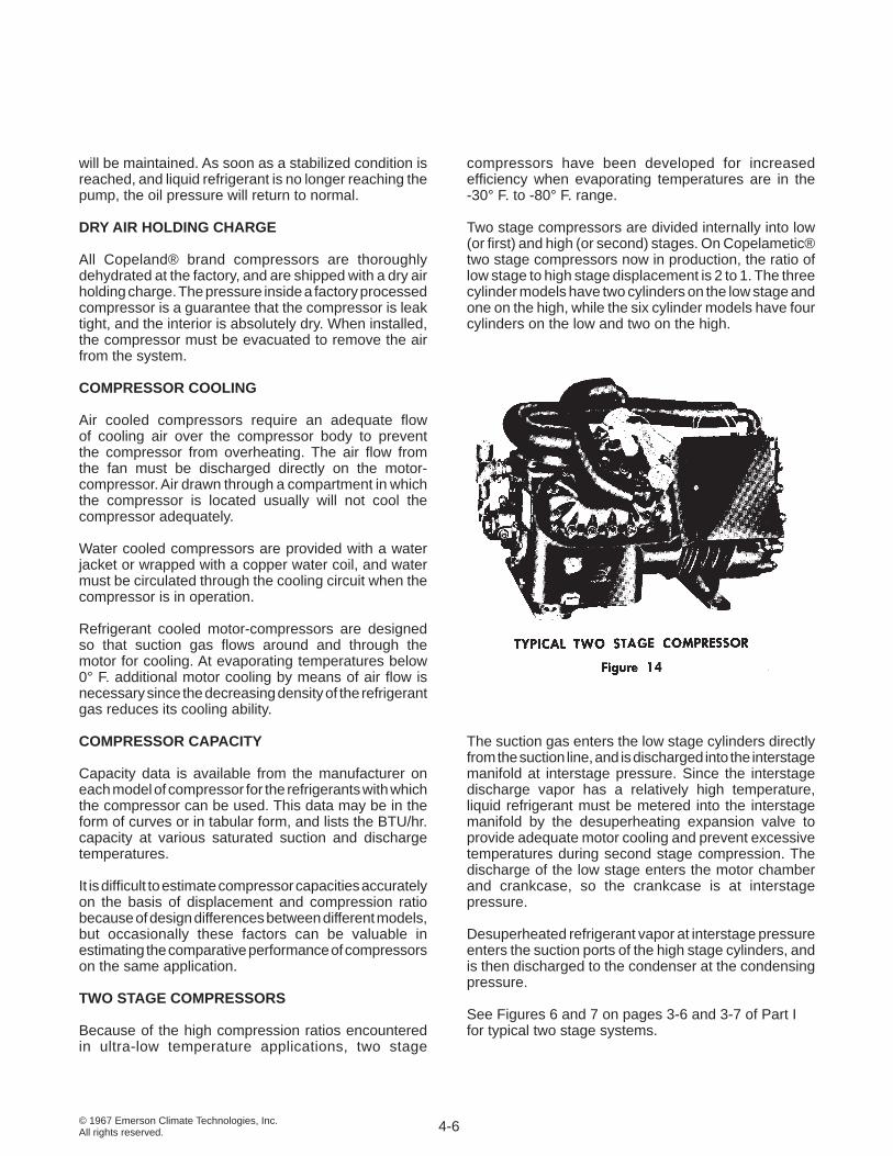
TWO STAGE COMPRESSORS Because of the high compression ratios encountered in ultra-low temperature applications, two stage
compressors have been developed for increased effi ciency when evaporating temperatures are in the -30° F. to -80° F. range.
Two stage compressors are divided internally into low (or fi rst) and high (or second) stages. On Copelametic® two stage compressors now in production, the ratio of low stage to high stage displacement is 2 to 1. The three cylinder models have two cylinders on the low stage and one on the high, while the six cylinder models have four cylinders on the low and two on the high.
The suction gas enters the low stage cylinders directly from the suction line, and is discharged into the interstage manifold at interstage pressure. Since the interstage discharge vapor has a relatively high temperature, liquid refrigerant must be metered into the interstage manifold by the desuperheating expansion valve to provide adequate motor cooling and prevent excessive temperatures during second stage compression. The discharge of the low stage enters the motor chamber and crankcase, so the crankcase is at interstage pressure.
Desuperheated refrigerant vapor at interstage pressure enters the suction ports of the high stage cylinders, and is then discharged to the condenser at the condensing pressure.
See Figures 6 and 7 on pages 3-6 and 3-7 of Part I for typical two stage systems.
4-6
© 1967 Emerson Climate Technologies, Inc.All rights reserved.
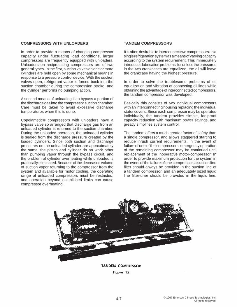
TANDEM COMPRESSORS It is often desirable to interconnect two compressors on a single refrigeration system as a means of varying capacity according to the system requirement. This immediately introduces lubrication problems, for unless the pressures in the two crankcases are equalized, the oil will leave the crankcase having the highest pressure.
In order to solve the troublesome problems of oil equalization and vibration of connecting oil lines while obtaining the advantage of interconnected compressors, the tandem compressor was developed.
Basically this consists of two individual compressors with an interconnecting housing replacing the individual stator covers. Since each compressor may be operated individually, the tandem provides simple, foolproof capacity reduction with maximum power savings, and greatly simplifi es system control.
The tandem offers a much greater factor of safety than a single compressor, and allows staggered starting to reduce inrush current requirements. In the event of failure of one of the compressors, emergency operation of the remaining compressor may be continued until replacement of the inoperative motor-compressor. In order to provide maximum protection for the system in the event of the failure of one compressor, a suction line fi lter should always be provided in the suction line of a tandem compressor, and an adequately sized liquid line fi lter-drier should be provided in the liquid line.
COMPRESSORS WITH UNLOADERS
In order to provide a means of changing compressor capacity under fl uctuating load conditions, larger compressors are frequently equipped with unloaders. Unloaders on reciprocating compressors are of two general types. In the fi rst, suction valves on one or more cylinders are held open by some mechanical means in response to a pressure control device. With the suction valves open, refrigerant vapor is forced back into the suction chamber during the compression stroke, and the cylinder performs no pumping action.
A second means of unloading is to bypass a portion of the discharge gas into the compressor suction chamber. Care must be taken to avoid excessive discharge temperatures when this is done.
Copelametic® compressors with unloaders have a bypass valve so arranged that discharge gas from an unloaded cylinder is returned to the suction chamber. During the unloaded operation, the unloaded cylinder is sealed from the discharge pressure created by the loaded cylinders. Since both suction and discharge pressures on the unloaded cylinder are approximately the same, the piston and cylinder do no work other than pumping vapor through the bypass circuit, and the problem of cylinder overheating while unloaded is practically eliminated. Because of the decreased volume of suction vapor returning to the compressor from the system and available for motor cooling, the operating range of unloaded compressors must be restricted, and operation beyond established limits can cause compressor overheating.
4-7
© 1967 Emerson Climate Technologies, Inc.All rights reserved.
The condenser is basically a heat exchanger where the heat absorbed by the refrigerant during the evaporating process is given off to the condensing medium. As mentioned previously, the heat given off by the condenser is always greater than the heat absorbed during the evaporating process because of the heat of compression. As heat is given off by the high temperature high pressure vapor, its temperature falls to the saturation point and the vapor condenses to a liquid, hence the name condenser.
AIR COOLED CONDENSERS
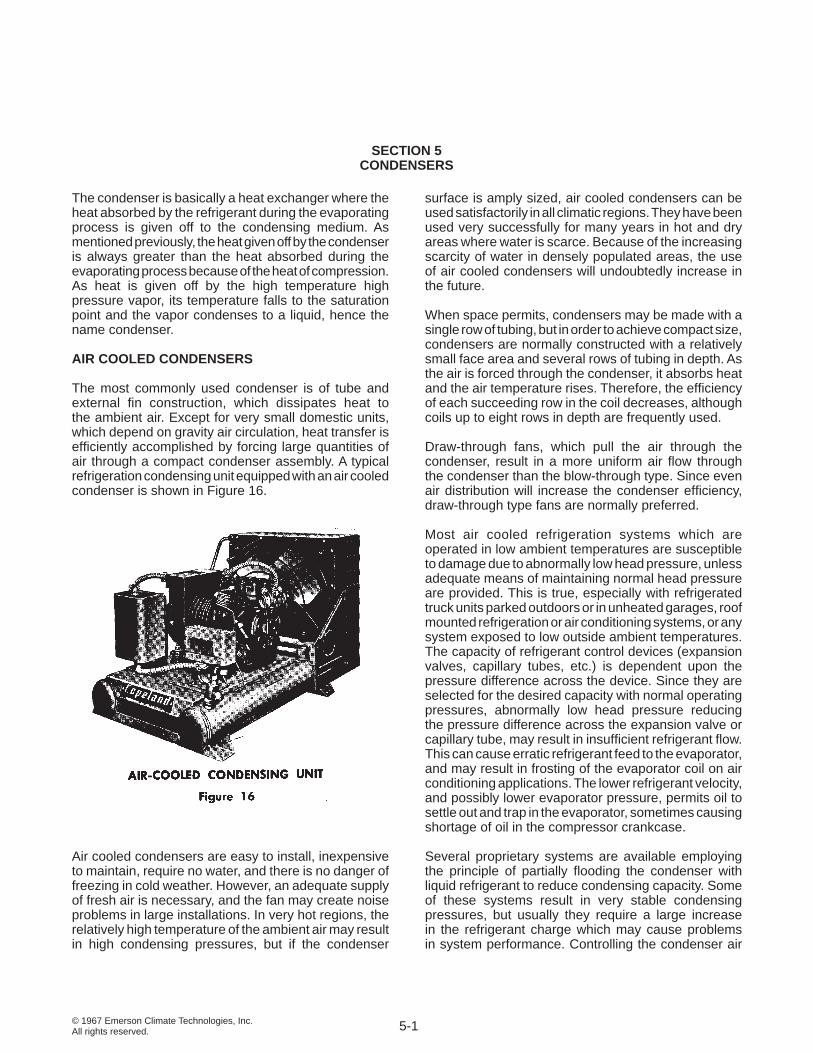
The most commonly used condenser is of tube and external fi n construction, which dissipates heat to the ambient air. Except for very small domestic units, which depend on gravity air circulation, heat transfer is effi ciently accomplished by forcing large quantities of air through a compact condenser assembly. A typical refrigeration condensing unit equipped with an air cooled condenser is shown in Figure 16.
Air cooled condensers are easy to install, inexpensive to maintain, require no water, and there is no danger of freezing in cold weather. However, an adequate supply of fresh air is necessary, and the fan may create noise problems in large installations. In very hot regions, the relatively high temperature of the ambient air may result in high condensing pressures, but if the condenser
surface is amply sized, air cooled condensers can be used satisfactorily in all climatic regions. They have been used very successfully for many years in hot and dry areas where water is scarce. Because of the increasing scarcity of water in densely populated areas, the use of air cooled condensers will undoubtedly increase in the future.
When space permits, condensers may be made with a single row of tubing, but in order to achieve compact size, condensers are normally constructed with a relatively small face area and several rows of tubing in depth. As the air is forced through the condenser, it absorbs heat and the air temperature rises. Therefore, the effi ciency of each succeeding row in the coil decreases, although coils up to eight rows in depth are frequently used.
Draw-through fans, which pull the air through the condenser, result in a more uniform air fl ow through the condenser than the blow-through type. Since even air distribution will increase the condenser effi ciency, draw-through type fans are normally preferred.
Most air cooled refrigeration systems which are operated in low ambient temperatures are susceptible to damage due to abnormally low head pressure, unless adequate means of maintaining normal head pressure are provided. This is true, especially with refrigerated truck units parked outdoors or in unheated garages, roof mounted refrigeration or air conditioning systems, or any system exposed to low outside ambient temperatures. The capacity of refrigerant control devices (expansion valves, capillary tubes, etc.) is dependent upon the pressure difference across the device. Since they are selected for the desired capacity with normal operating pressures, abnormally low head pressure reducing the pressure difference across the expansion valve or capillary tube, may result in insuffi cient refrigerant fl ow. This can cause erratic refrigerant feed to the evaporator, and may result in frosting of the evaporator coil on air conditioning applications. The lower refrigerant velocity, and possibly lower evaporator pressure, permits oil to settle out and trap in the evaporator, sometimes causing shortage of oil in the compressor crankcase.
Several proprietary systems are available employing the principle of partially fl ooding the condenser with liquid refrigerant to reduce condensing capacity. Some of these systems result in very stable condensing pressures, but usually they require a large increase in the refrigerant charge which may cause problems in system performance. Controlling the condenser air
SECTION 5 CONDENSERS
5-1
© 1967 Emerson Climate Technologies, Inc.All rights reserved.
fl ow by means of louvers is also an effective means of condensing pressure control. Cycling the condenser fan is a simple but less effective means of control.
WATER COOLED CONDENSERS
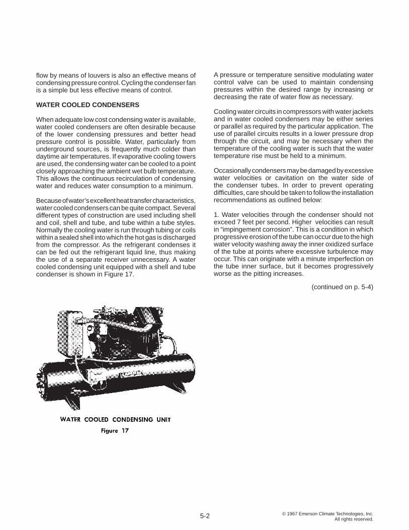
When adequate low cost condensing water is available, water cooled condensers are often desirable because of the lower condensing pressures and better head pressure control is possible. Water, particularly from underground sources, is frequently much colder than daytime air temperatures. If evaporative cooling towers are used, the condensing water can be cooled to a point closely approaching the ambient wet bulb temperature. This allows the continuous recirculation of condensing water and reduces water consumption to a minimum.
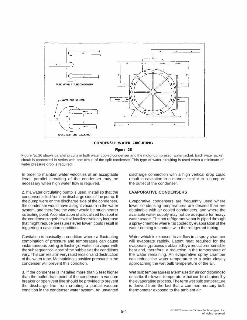
Because of water’s excellent heat transfer characteristics, water cooled condensers can be quite compact. Several different types of construction are used including shell and coil, shell and tube, and tube within a tube styles. Normally the cooling water is run through tubing or coils within a sealed shell into which the hot gas is discharged from the compressor. As the refrigerant condenses it can be fed out the refrigerant liquid line, thus making the use of a separate receiver unnecessary. A water cooled condensing unit equipped with a shell and tube condenser is shown in Figure 17.
A pressure or temperature sensitive modulating water control valve can be used to maintain condensing pressures within the desired range by increasing or decreasing the rate of water fl ow as necessary.
Cooling water circuits in compressors with water jackets and in water cooled condensers may be either series or parallel as required by the particular application. The use of parallel circuits results in a lower pressure drop through the circuit, and may be necessary when the temperature of the cooling water is such that the water temperature rise must be held to a minimum. Occasionally condensers may be damaged by excessive water velocities or cavitation on the water side of the condenser tubes. In order to prevent operating diffi culties, care should be taken to follow the installation recommendations as outlined below:
1. Water velocities through the condenser should not exceed 7 feet per second. Higher velocities can result in “impingement corrosion”. This is a condition in which progressive erosion of the tube can occur due to the high water velocity washing away the inner oxidized surface of the tube at points where excessive turbulence may occur. This can originate with a minute imperfection on the tube inner surface, but it becomes progressively worse as the pitting increases.
5-2
(continued on p. 5-4)
© 1967 Emerson Climate Technologies, Inc.All rights reserved.
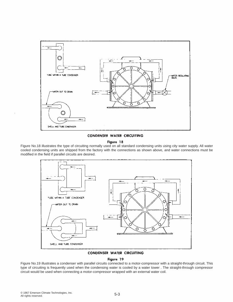
Figure No.18 illustrates the type of circuiting normally used on all standard condensing units using city water supply. All water cooled condensing units are shipped from the factory with the connections as shown above, and water connections must be modifi ed in the fi eld if parallel circuits are desired.
Figure No.19 illustrates a condenser with parallel circuits connected to a motor-compressor with a straight-through circuit. This type of circuiting is frequently used when the condensing water is cooled by a water tower . The straight-through compressor circuit would be used when connecting a motor-compressor wrapped with an external water coil.
5-3
© 1967 Emerson Climate Technologies, Inc.All rights reserved.
discharge connection with a high vertical drop could result in cavitation in a manner similar to a pump on the outlet of the condenser.
EVAPORATIVE CONDENSERS
Evaporative condensers are frequently used where lower condensing temperatures are desired than are obtainable with air cooled condensers, and where the available water supply may not be adequate for heavy water usage. The hot refrigerant vapor is piped through a spray chamber where it is cooled by evaporation of the water coming in contact with the refrigerant tubing.
Water which is exposed to air fl ow in a spray chamber will evaporate rapidly. Latent heat required for the evaporating process is obtained by a reduction in sensible heat and, therefore, a reduction in the temperature of the water remaining. An evaporative spray chamber can reduce the water temperature to a point closely approaching the wet bulb temperature of the air.
Wet bulb temperature is a term used in air conditioning to describe the lowest temperature that can be obtained by the evaporating process. The term wet bulb temperature is derived from the fact that a common mercury bulb thermometer exposed to the ambient air
Figure No.20 shows parallel circuits in both water cooled condenser and the motor-compressor water jacket. Each water jacket circuit is connected in series with one circuit of the split condenser. This type of water circuiting is used when a minimum of water pressure drop is required.
In order to maintain water velocities at an acceptable level, parallel circuiting of the condenser may be necessary when high water fl ow is required. 2. If a water circulating pump is used, install so that the condenser is fed from the discharge side of the pump. If the pump were on the discharge side of the condenser, the condenser would have a slight vacuum in the water system, and therefore the water would be much nearer its boiling point. A combination of a localized hot spot in the condenser together with a localized velocity increase that might reduce pressures even lower, could result in triggering a cavitation condition.
Cavitation is basically a condition where a fl uctuating combination of pressure and temperature can cause instantaneous boiling or fl ashing of water into vapor, with the subsequent collapse of the bubbles as the conditions vary. This can result in very rapid erosion and destruction of the water tube. Maintaining a positive pressure in the condenser will prevent this condition.
3. If the condenser is installed more than 5 feet higher than the outlet drain point of the condenser, a vacuum breaker or open vent line should be provided to prevent the discharge line from creating a partial vacuum condition in the condenser water system. An unvented
5-4
© 1967 Emerson Climate Technologies, Inc.All rights reserved.
indicates the dry bulb or ambient temperature, while if a wick wetted with water is placed around the mercury bulb and the thermometer is exposed to rapid air movement, the temperature indicated by the thermometer will be the wet bulb temperature. The difference between the dry bulb and wet bulb readings is determined by the rate of evaporation from the wet surface of the wick, and this in turn is proportional to the moisture content or vapor pressure of the air. The wet bulb temperature is always lower than the dry bulb temperature, and for a given dry bulb, the less the moisture content of the air, the lower the wet bulb temperature will be.
Since the cooling is accomplished by evaporation of the water, water consumption is only a fraction of that used in conventional water cooled applications in which the water once used is discharged to a drain. Evaporative condensing is therefore widely used in hot, arid regions of the world.
Corrosion, scale formation, and the danger of freezing are problems that must be solved with both evaporative and water cooled condensers. With both cooling towers and evaporative condensers, a bleed to a drain must be provided to prevent the concentration of contaminants in the cooling water.
CONDENSER CAPACITY
The heat transfer capacity of a condenser depends upon several factors:
1. Surface area of the condenser .
2. Temperature difference between the cooling medium and the refrigerant gas.
3. Velocity of the refrigerant gas in the condenser tubes. Within the normal commercial operating range, the greater the velocity, the better the heat transfer factor, and the greater the capacity.
4. Rate of fl ow of the cooling medium over or through the condenser. Heat transfer increases with velocity for both air and water, and in the case of air, it also increases with density.
5. Material of which the condenser is made. Since heat transfer differs with different materials, more effi cient metals will increase the capacity.
6. Cleanliness of the heat transfer surface. Dirt, scale, or corrosion can reduce the heat transfer rate.
For a given condenser, the physical characteristics are fi xed, and the primary variable is the temperature
difference between the refrigerant gas and the condensing medium.
CONDENSING TEMPERATURE
The condensing temperature is the temperature at which the refrigerant gas is condensing from a vapor to a liquid. This should not be confused with the temperature of the cooling medium, since the condensing temperature must always be higher in order for heat transfer to take place.
In order to condense the refrigerant vapor fl owing into the condenser, heat must fl ow from the condenser at the same rate at which heat is introduced by the refrigerant gas entering the condenser. As mentioned previously, the only way in which the capacity of the condenser can be increased under a given set of conditions is by an increase in the temperature difference through the condenser walls.
Since a reciprocating compressor is a positive displacement machine, the pressure in the condenser will continue to increase until such time as the temperature difference between the cooling medium and the refrigerant condensing temperature is suffi ciently great to transfer the necessary amount of heat. With a large condenser, this temperature difference may be very small. With a small condenser or in the event air or water fl ow to the condenser has been blocked, the necessary temperature difference may be very large. This can result in dangerously high pressures, and it is essential that the condenser is operating properly any time a refrigeration unit is in operation.
The condensing temperature and therefore the condensing pressure is determined by the capacity of the condenser, the temperature of the cooling medium, and the heat content of the refrigerant gas being discharged from the compressor, which in turn is determined by the volume, density and temperature of the gas discharged.
NON-CONDENSABLE GASES
Air is primarily composed of nitrogen and oxygen, and both elements remain in gaseous form at all temperatures and pressures encountered in commercial refrigeration and air conditioning systems. Therefore, although these gases can be liquefi ed under extremely high pressures and extremely low temperatures, they may be considered as non-condensable in a refrigeration system.
Scientists have discovered that one of the basic laws of nature is the fact that in a combination of gases, each gas exerts its own pressure independently of others,
5-5
© 1967 Emerson Climate Technologies, Inc.All rights reserved.
and the total pressure existing in a system is the total of all the gaseous pressures present. A second basic characteristic of a gas is that if the space in which it is enclosed remains constant, so that it cannot expand, its pressure will vary directly with the temperature. Therefore, if air is sealed in a system with refrigerant, the nitrogen and oxygen will each add their pressure to the system pressure, and this will increase as the temperature rises.
Since the air is non-condensable, it will usually trap in the top of the condenser and the receiver. During operation the compressor discharge pressure will be a combination of the refrigerant condensing pressure plus the pressure exerted by the nitrogen and oxygen. The amount of pressure above normal condensing pressure that may result will depend on the amount of trapped air, but it can easily reach 40 to 50 psig or more. Any time a system is running with abnormally high head pressure, air in the system is a prime suspect .
CONDENSING TEMPERATURE DIFFERENCE
A condenser is normally selected for a system by sizing it to handle the compressor load at a desired temperature difference between the condensing temperature and the expected temperature of the cooling medium. Most air cooled condensers are selected to operate on temperature differences (commonly called TD) of 20° F. to 30° F. at design conditions, but higher and lower TDs are sometimes used on specialized applications. Standard production air cooled condensing units are often designed with one condenser for a wide range of applications. In order to cover as wide a range as possible, the TD at high suction pressures may be from 30° F. to 40° F., while at low evaporating temperatures the TD often is no more than 4° F. to 10° F. The design condensing temperature on water cooled units is normally determined by the temperature of the water supply and the water fl ow rate available, and may vary from 90° F. to 120° F.
Since the condenser capacity must be greater than the evaporator capacity by the heat of compression and the motor effi ciency loss, the condenser manufacturer may rate condensers in terms of evaporator capacity, or may recommend a factor to allow for the heat of compression in selecting the proper condenser size.
5-6
© 1967 Emerson Climate Technologies, Inc.All rights reserved.
SECTION 6 EVAPORATORS
The evaporator is that part of the low pressure side of the refrigeration system in which the liquid refrigerant boils or evaporates, absorbing heat as it changes into a vapor. It accomplishes the actual purpose of the system, refrigeration.
TYPES OF EVAPORATORS
Evaporators are made in many different shapes and styles to fi ll specifi c needs. The most common style is the blower coil or forced convection evaporator in which the refrigerant evaporates inside of fi nned tubes, extracting heat from air blown through the coil by a fan. However, specifi c applications may use bare coils with no fi ns, gravity coils with natural convection air fl ow, fl at plate surface, or other specialized types of heat transfer surface.
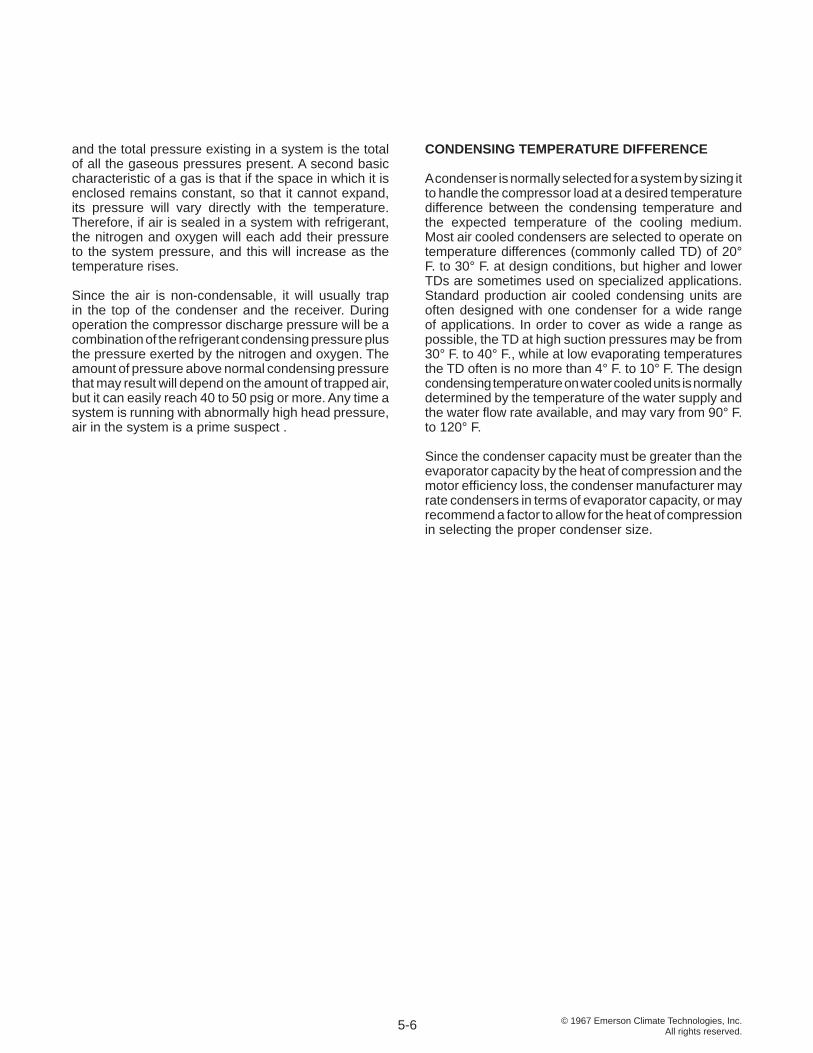
Direct expansion evaporators are those in which the refrigerant is fed directly into the cooling coil through a metering device such as an expansion valve or capillary tube, absorbing the heat directly through the walls of the evaporator from the medium to be cooled. Figure 21 shows a direct expansion coil of one manufacturer prior to assembly in a blower unit.
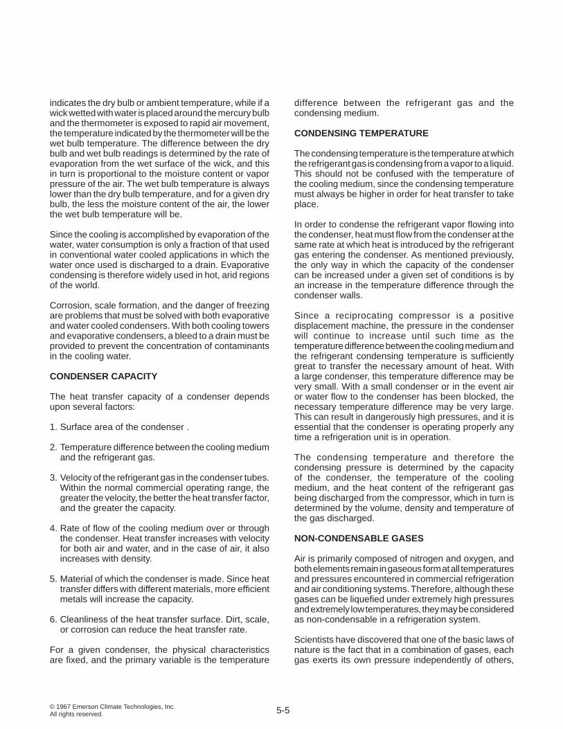
In other types of systems, secondary refrigerants such as chilled water or brine may be used for the actual space or product refrigeration while the evaporator is the water or brine chiller. A complete packaged water chiller, designed to furnish chilled water for air conditioning or other cooling applications is shown in Figure 22.
BLOWER COIL CONSTRUCTION
A typical blower coil is made up of a direct expansion coil, mounted in a metal housing complete with a fan for forced air circulation. The coil is normally constructed of copper tubing supported in metal tube sheets, with aluminum fi ns on the tubing to increase heat transfer effi ciency.
If the evaporator is quite small, there may be only one continuous circuit in the coil, but as the size increases, the increasing pressure drop through the longer circuit makes it necessary to divide the evaporator into several individual circuits emptying into a common header. The various circuits are usually fed through a distributor which equalizes the feed in each circuit in order to maintain high evaporator effi ciency.
The spacing of fi ns on the refrigerant tubing will vary depending on the application. Low temperature coils may have as few as two fi ns per inch, while air conditioning coils may have up to twelve per inch or more. In general
6-1
© 1967 Emerson Climate Technologies, Inc.All rights reserved.
if the evaporator temperature is to be below 32° F. so that frost will accumulate, fi n spacings of 4 per inch or less are commonly used, although closer fi n spacings are sometimes used if effi cient defrost systems are available. In air conditioning applications, icing of the coil is seldom a problem, and the limit on fi n spacing may be dictated by the coil’s resistance to air fl ow.
Since the heat transfer effi ciency of the coil increases with an increase in the mass fl ow of air passing through it, high velocities are desirable. However at face velocities greater than 500 to 600 FPM, water collecting on the coil from condensation will be blown off into the air stream, and except for specialized applications, these velocities are seldom exceeded.
PRESSURE DROP AND OTHER FACTORS IN EVAPORATOR DESIGN
As mentioned previously, pressure drop occurring in the evaporator results in a loss of system capacity due to the lower pressure at the outlet of the evaporator coil. With a reduction in suction pressure, the specifi c volume of the gas returning to the compressor increases, and the weight of the refrigerant pumped by the compressor decreases.
However there are other factors which must also be considered in evaporator design. If the evaporator tubing is too large, refrigerant gas velocities may become so low that oil will accumulate in the tubing and will not be returned to the compressor. The only means of assuring satisfactory oil circulation is by maintaining adequate gas velocities. The heat transfer ability of the tubing may also be greatly decreased if velocities are not suffi cient to scrub the interior tubing wall, and keep it clear of an oil fi lm. The goals of low pressure drop and high velocities are directly opposed, so the fi nal evaporator design must be a compromise.
Pressure drops through the evaporator of approximately 1 to 2 psi are acceptable on most medium and high temperature applications, and 1/2 to 1 psi are common in low temperature evaporators.
EVAPORATOR CAPACITY
The factors affecting evaporator capacity are quite similar to those affecting condenser capacity.
1. Surface area or size of the evaporator .
2. Temperature difference between the evaporating refrigerant and the medium being cooled.
3. Velocity of gas in the evaporator tubes. In the normal
commercial range, the higher the velocity the greater the heat transfer rate.
4. The velocity and rate of fl ow over the evaporator surface of the medium being cooled.
5. Material used in evaporator construction.
6. The bond between the fi ns and tubing is quite important. Without a tight bond, heat transfer will be greatly decreased.
7. Accumulation of frost on evaporator fi ns. Operation at temperatures below freezing with blower coils will cause the formation of ice and frost on the tubes and fi ns. This can both reduce the air fl ow over the evaporator and reduce the heat transfer rate.
8. Type of medium to be cooled. Heat fl ows almost fi ve times more effectively from a liquid to the evaporator than from air .
9. Dewpoint of the entering air. If the evaporator temperature is below the dewpoint of the entering air, latent as well as sensible cooling will occur.
TEMPERATURE DIFFERENCE AND DEHUMIDIFICATION
Since for a given installation, the physical characteristics are fi xed, the primary variable as in the case of the condenser, is the temperature difference between the evaporating refrigerant and the medium being cooled, commonly called the TD. For a blower coil, the colder the refrigerant with respect to the temperature of the air entering the evaporator, the greater will be the capacity of the coil.
Temperature differences of 5° F. to 20° F. are commonly used. Usually for best economy, the TD should be kept as low as possible, since operation of the compressor will be more effi cient at higher suction pressures.
The amount of moisture condensed out of the air is in direct relation to the temperature of the coil, and a coil operating with too great a differential between the evaporating temperature and the entering air temperature will tend to produce a low humidity condition in the refrigerated space. In the storage of leafy vegetables, meats, fruits, and other similar perishable items, low humidity will result in excessive dehydration and damage to the product. For perishable commodities requiring a very high relative humidity (approximately 90%) a TD from 8° F. to 12° F. is recommended, and for relative humidities slightly lower (approximately 80%) a TD from 12° F. to 16° F. is normally adequate.
6-2
© 1967 Emerson Climate Technologies, Inc.All rights reserved.
DEFROSTING OF BLOWER COILS
Ice and frost will accumulate continuously on coils operating below freezing temperatures, and air fl ow through the coil will be eventually blocked unless the frost is removed. To allow continuous operation on refrigeration applications where frost accumulation can occur, periodic defrost cycles are necessary.
If the air returning to the evaporator is well above 32° F., defrosting can be accomplished by allowing the fan to continue operation while the compressor is shut down, either for a preset time period or until the coil temperature rises a few degrees above 32° F., the melting temperature of the frost.
For low temperature applications, some source of heat must be supplied to melt the ice. Electric defrost systems
utilize electric heater coils or rods in the evaporator. Proprietary systems using water for defrosting are available. Hot gas defrosting is widely used, with the discharge gas from the compressor bypassing the condenser and discharging directly into the evaporator inlet. In hot gas defrost systems, the heat of compression or some source of stored heat provides defrost heat, and adequate protective devices such as re-evaporators or suction accumulators must be provided if necessary to prevent liquid refrigerant from returning to the compressor. Other systems may utilize reverse cycle defrosting, in which the fl ow of refrigerant is reversed to convert the evaporator temporarily into a condenser until the defrost period is complete.
To prevent refreezing of the melted condensate in the evaporator drain pan, a drain pan heater is required on low temperature systems.
6-3
© 1967 Emerson Climate Technologies, Inc.All rights reserved.
SECTION 7 CONTROL DEVICES, REFRIGERANT
In modern refrigeration practice, a wide variety of refrigerant control devices are used to obtain effi cient economic operation. Small systems with manual control or simple “on-off” automatic control may require only one or two controls, but large systems with more elaborate automatic control may have a multitude of controls, the proper operation of each being essential to the satisfactory performance of the system.
In order to adjust a control for effi cient performance, or recognize the effect of a malfunction, it is essential that the function, operation, and application of each refrigeration control be completely understood.
THERMOSTATIC EXPANSION VALVES
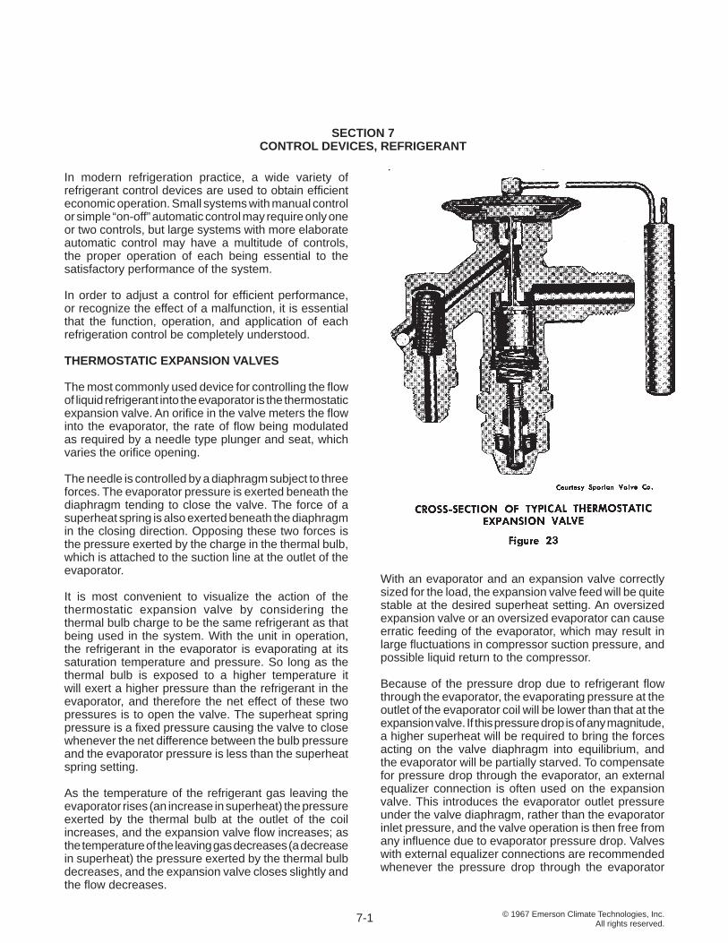
The most commonly used device for controlling the fl ow of liquid refrigerant into the evaporator is the thermostatic expansion valve. An orifi ce in the valve meters the fl ow into the evaporator, the rate of fl ow being modulated as required by a needle type plunger and seat, which varies the orifi ce opening.
The needle is controlled by a diaphragm subject to three forces. The evaporator pressure is exerted beneath the diaphragm tending to close the valve. The force of a superheat spring is also exerted beneath the diaphragm in the closing direction. Opposing these two forces is the pressure exerted by the charge in the thermal bulb, which is attached to the suction line at the outlet of the evaporator.
It is most convenient to visualize the action of the thermostatic expansion valve by considering the thermal bulb charge to be the same refrigerant as that being used in the system. With the unit in operation, the refrigerant in the evaporator is evaporating at its saturation temperature and pressure. So long as the thermal bulb is exposed to a higher temperature it will exert a higher pressure than the refrigerant in the evaporator, and therefore the net effect of these two pressures is to open the valve. The superheat spring pressure is a fi xed pressure causing the valve to close whenever the net difference between the bulb pressure and the evaporator pressure is less than the superheat spring setting.
As the temperature of the refrigerant gas leaving the evaporator rises (an increase in superheat) the pressure exerted by the thermal bulb at the outlet of the coil increases, and the expansion valve fl ow increases; as the temperature of the leaving gas decreases (a decrease in superheat) the pressure exerted by the thermal bulb decreases, and the expansion valve closes slightly and the fl ow decreases.
With an evaporator and an expansion valve correctly sized for the load, the expansion valve feed will be quite stable at the desired superheat setting. An oversized expansion valve or an oversized evaporator can cause erratic feeding of the evaporator, which may result in large fl uctuations in compressor suction pressure, and possible liquid return to the compressor.
Because of the pressure drop due to refrigerant fl ow through the evaporator, the evaporating pressure at the outlet of the evaporator coil will be lower than that at the expansion valve. If this pressure drop is of any magnitude, a higher superheat will be required to bring the forces acting on the valve diaphragm into equilibrium, and the evaporator will be partially starved. To compensate for pressure drop through the evaporator, an external equalizer connection is often used on the expansion valve. This introduces the evaporator outlet pressure under the valve diaphragm, rather than the evaporator inlet pressure, and the valve operation is then free from any infl uence due to evaporator pressure drop. Valves with external equalizer connections are recommended whenever the pressure drop through the evaporator
7-1
© 1967 Emerson Climate Technologies, Inc.All rights reserved.
is above 2 1/2 psi for high temperature applications, 1 1/2 psi in the medium temperature range, and 1/2 psi in the low temperature range. Valves with external equalizers must be employed when a pressure drop type of distributor is used.
Pressure limiting expansion valves are often used to limit the power requirement of the compressor. The valve is constructed in such a manner that it limits the suction pressure to a given maximum value, and restricts the refrigerant feed if the suction pressure rises above that point.
Gas charged pressure limiting valves have a limited charge, and at temperatures of the thermal bulb equivalent to its maximum operating pressure, all of the liquid charge has vaporized, and any further increase in temperature can only superheat the gas, but cannot exert additional pressure. Any increase in evaporator pressure will then act as a closing force on the expansion valve. The disadvantage of the gas charged valve is the possibility of the limited charge condensing in the head of the expansion valve, if the head is colder than the thermal bulb, causing the valve to lose control of the liquid feed. With gas charged valves, the thermal bulb must always be colder than the head of the valve, and the gas charged valve normally is used only on high temperature applications such as air conditioning.
Mechanical limiting valves are available, usually with a spring loaded double diaphragm type construction. If the evaporator reaches a preset pressure, the diaphragm collapses, and the valve feed is restricted until the pressure decreases suffi ciently for the spring tension to restore the diaphragm to its normal operating position.
In order to achieve closer control for varying applications, expansion valves are available with different types of charge in the thermal bulb, each having different operating characteristics. The superheat spring is also normally equipped with an external adjusting screw so that it can be set for the desired superheat on a given application. Before adjusting any expansion valve, the exact characteristics of the valve should be thoroughly understood. The manufacturer’s catalog data must be consulted for detailed information on a given valve.
OTHER TYPES OF EXPANSION VALVES
The automatic expansion valve is really better described as a constant pressure expansion valve, since it modulates its feed to maintain a constant preset pressure in the evaporator. The automatic expansion valve was widely used at one time, but because of its tendency
to starve the evaporator on heavy loads, and fl ood the evaporator on light loads, it has been largely replaced by the thermostatic expansion valve and capillary tubes.
Hand expansion valves are sometimes used when an operator is available and manual liquid refrigerant feed is acceptable. A needle valve is adjusted as required to maintain the desired fl ow.
DISTRIBUTORS
When the refrigeration load is such that large evaporators are required, multiple refrigerant circuits are necessary to avoid excessive pressure drop through the evaporator. To insure uniform feed from the expansion valve to each of the various circuits, a refrigerant distributor is normally used. A typical distributor mounted on a direct expansion coil is shown in Figure 21, page 6-1.
As liquid refrigerant is fed through the expansion valve, a portion of the liquid fl ashes into vapor in order to reduce the liquid temperature to evaporator temperature. This combination of liquid and fl ash gas is fed into the distributor from the expansion valve, and is then distributed evenly through small feeder tubes, the number depending on the construction of the distributor and the number of circuits required to provide proper refrigerant velocity in the evaporator .
Without the distributor, the fl ow would separate into separate gas and liquid layers, resulting in the starving of some evaporator circuits. To avoid variations in circuit feed, extreme care must be taken to insure that tubing lengths are equal, so equal resistance is offered by each circuit.
There are two different approaches in the design of a distributor. A high-pressure drop distributor depends on the turbulence created by an orifi ce to achieve good distribution. A low-pressure drop distributor depends on a contour fl ow pattern with high velocity in the distributor throat to give proper distribution of the refrigerant fl ow. Both types of distributor give satisfactory performance when properly applied in accordance with the manufacturer’s instructions.
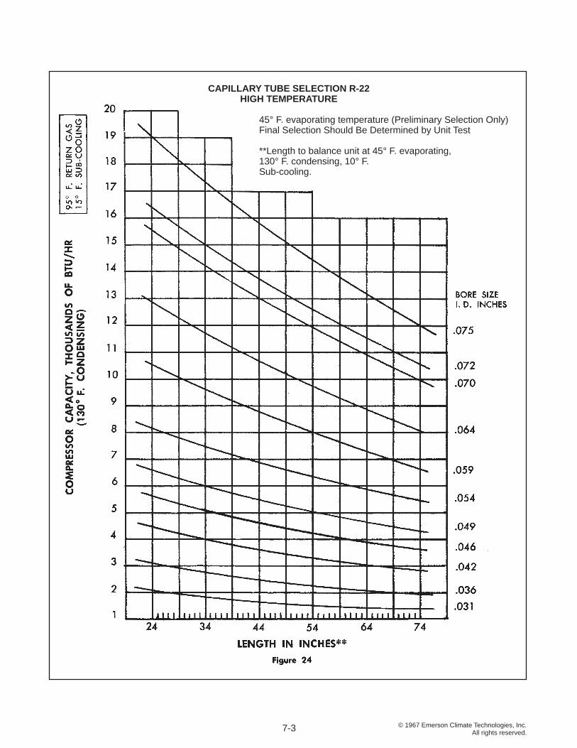
CAPILLARY TUBES
On small unitary equipment such as package air conditioners, domestic refrigeration equipment, and self-contained commercial refrigeration cases, capillary tubes are widely used for liquid refrigerant control. A capillary tube is a length of tubing of small diameter with the internal diameter held to extremely close tolerances. It is used as a fi xed orifi ce to perform the same function
7-2
(continued on p. 7-8)
© 1967 Emerson Climate Technologies, Inc.All rights reserved.
CAPILLARY TUBE SELECTION R-22 HIGH TEMPERATURE
45° F. evaporating temperature (Preliminary Selection Only) Final Selection Should Be Determined by Unit Test
**Length to balance unit at 45° F. evaporating, 130° F. condensing, 10° F. Sub-cooling.
7-3
© 1967 Emerson Climate Technologies, Inc.All rights reserved.
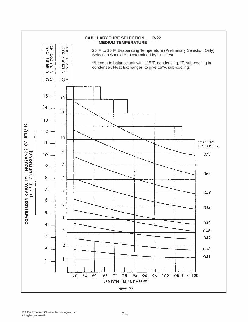
CAPILLARY TUBE SELECTION R-22MEDIUM TEMPERATURE
25°F, to 10°F. Evaporating Temperature (Preliminary Selection Only) Selection Should Be Determined by Unit Test
**Length to balance unit with 115°F. condensing, °F. sub-cooling in condenser, Heat Exchanger to give 15°F. sub-cooling.
7-4
© 1967 Emerson Climate Technologies, Inc.All rights reserved.
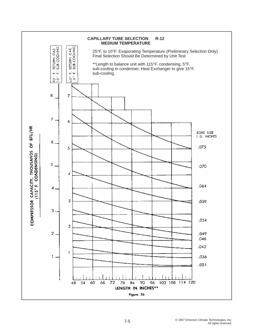
CAPILLARY TUBE SELECTION R-12MEDIUM TEMPERATURE
25°F, to 10°F. Evaporating Temperature (Preliminary Selection Only) Final Selection Should Be Determined by Unit Test
**Length to balance unit with 115°F. condensing, 5°F. sub-cooling in condenser, Heat Exchanger to give 15°F. sub-cooling.
7-5
© 1967 Emerson Climate Technologies, Inc.All rights reserved.
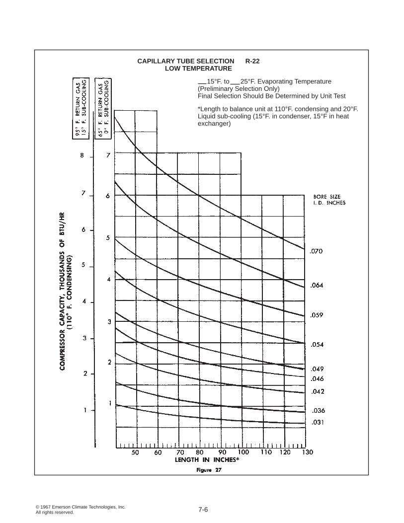
CAPILLARY TUBE SELECTION R-22LOW TEMPERATURE
15°F. to 25°F. Evaporating Temperature (Preliminary Selection Only)Final Selection Should Be Determined by Unit Test
*Length to balance unit at 110°F. condensing and 20°F. Liquid sub-cooling (15°F. in condenser, 15°F in heat exchanger)
7-6
© 1967 Emerson Climate Technologies, Inc.All rights reserved.
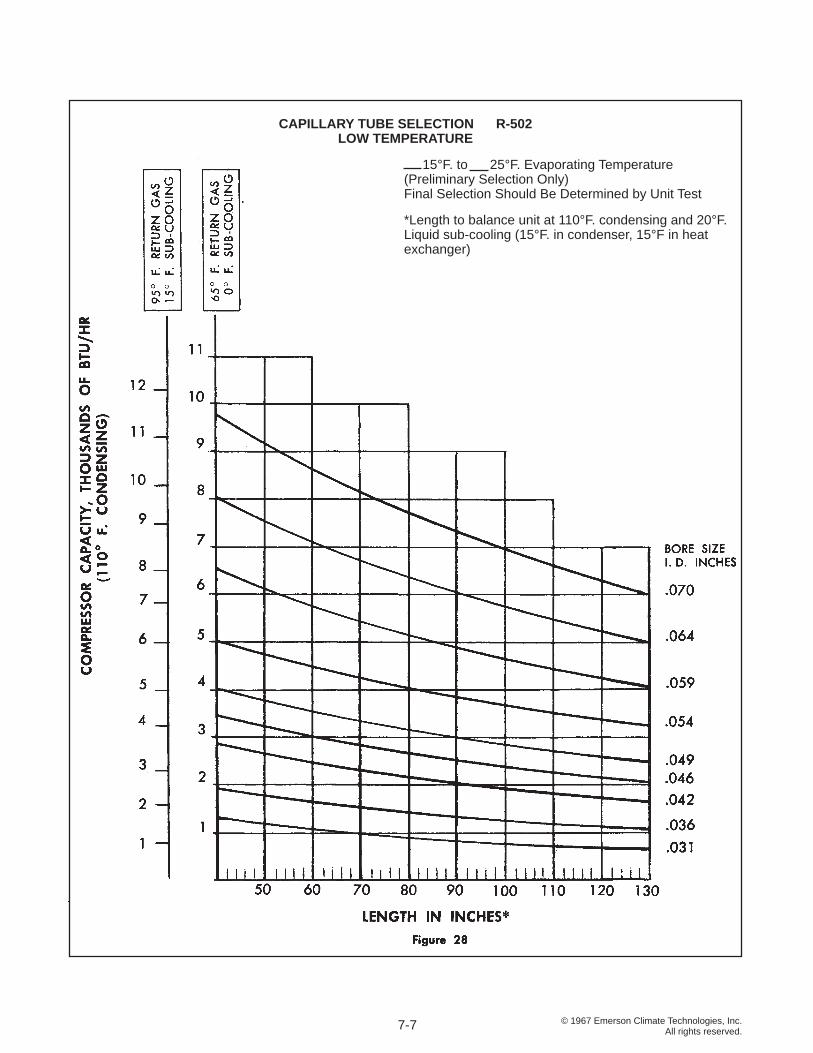
CAPILLARY TUBE SELECTION R-502LOW TEMPERATURE
15°F. to 25°F. Evaporating Temperature (Preliminary Selection Only)Final Selection Should Be Determined by Unit Test
*Length to balance unit at 110°F. condensing and 20°F. Liquid sub-cooling (15°F. in condenser, 15°F in heat exchanger)
7-7
© 1967 Emerson Climate Technologies, Inc.All rights reserved.
as the expansion valve, to separate the high and low pressure sides of the system, and meter the proper feed of liquid refrigerant.
Since there are no moving parts, it is simple and trouble free if kept free of foreign material. A capillary tube is of very small diameter, and absolute freedom from foreign matter and moisture is essential, making a factory sealed unit a practical necessity.
Since the orifi ce is fi xed, the rate of feed is relatively infl exible. Under conditions of constant load, and constant discharge and suction pressures, the capillary tube performs very satisfactorily. However, changes in the evaporator load or fl uctuations in head pressure can result in under or over feeding of the evaporator.
A major advantage of the capillary tube in some systems is the fact that refrigerant continues to fl ow into the evaporator after the compressor stops operation, thus equalizing pressures on the high and low sides of the system. This allows the use of low starting torque motors.
The refrigerant charge is critical in capillary tube systems since normally there is no receiver to store excess refrigerant. Too much refrigerant will cause high discharge pressures and motor overloading, and possible liquid fl oodback to the compressor during the off cycle; too little will allow vapor to enter the capillary tube causing a loss in system capacity.
Due to its basic simplicity, the elimination of the need for a receiver, and the low starting torque requirement, a capillary tube system is the least expensive of all liquid control systems.
Sizing of a capillary tube is diffi cult to calculate accurately, and can best be determined by actual test on the system. Once determined, the proper size capillary tube can be applied to identical systems, so it is well adapted to production units. Figures 24, 25, 26, 27, and 28 give tentative selection data for capillary tubes.
FLOAT VALVES
On some specialized applications, it may be desirable to operate with completely fl ooded systems, that is, with the evaporator completely fi lled with liquid refrigerant. A typical application might be an industrial process cooling installation where a brine or liquid is piped through a chiller shell in which the refrigerant level is to be maintained. Special liquid level controls are available from expansion valve manufacturers. These normally are mounted in a secondary fl oat chamber and modulate fl ow as necessary
to maintain a given liquid level. Such applications are quite specialized and the manufacturer’s instructions should be followed closely. Unless some means is provided for positive oil return, oil may accumulate in a fl oat chamber causing lubrication diffi culties.
Commercial or domestic applications using either high side or low side fl oat chambers for liquid feed have been largely replaced by capillary tube and expansion valve control.
SOLENOID VALVES
A solenoid valve is an electrically controlled refrigerant fl ow control valve. It is not a modulating valve, and is either open or closed.
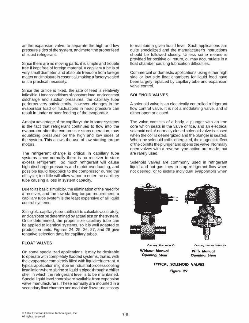
The valve consists of a body, a plunger with an iron core which seats in the valve orifi ce, and an electrical solenoid coil. A normally closed solenoid valve is closed when the coil is deenergized and the plunger is seated. When the solenoid coil is energized, the magnetic effect of the coil lifts the plunger and opens the valve. Normally open valves with a reverse type action are made, but are rarely used.
Solenoid valves are commonly used in refrigerant liquid and hot gas lines to stop refrigerant fl ow when not desired, or to isolate individual evaporators when
7-8
© 1967 Emerson Climate Technologies, Inc.All rights reserved.
multiple evaporators are used. On large installations, large numbers of solenoid valves may be necessary for satisfactory automatic control.
CRANKCASE PRESSURE REGULATING VALVES
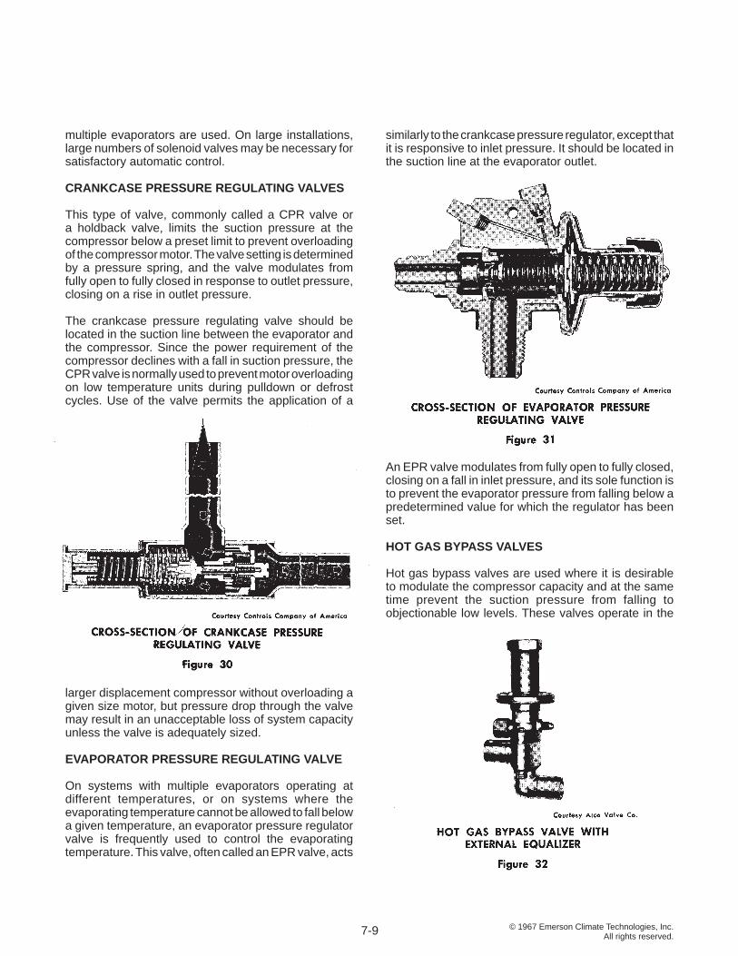
This type of valve, commonly called a CPR valve or a holdback valve, limits the suction pressure at the compressor below a preset limit to prevent overloading of the compressor motor. The valve setting is determined by a pressure spring, and the valve modulates from fully open to fully closed in response to outlet pressure, closing on a rise in outlet pressure.
The crankcase pressure regulating valve should be located in the suction line between the evaporator and the compressor. Since the power requirement of the compressor declines with a fall in suction pressure, the CPR valve is normally used to prevent motor overloading on low temperature units during pulldown or defrost cycles. Use of the valve permits the application of a
larger displacement compressor without overloading a given size motor, but pressure drop through the valve may result in an unacceptable loss of system capacity unless the valve is adequately sized.
EVAPORATOR PRESSURE REGULATING VALVE
On systems with multiple evaporators operating at different temperatures, or on systems where the evaporating temperature cannot be allowed to fall below a given temperature, an evaporator pressure regulator valve is frequently used to control the evaporating temperature. This valve, often called an EPR valve, acts
similarly to the crankcase pressure regulator, except that it is responsive to inlet pressure. It should be located in the suction line at the evaporator outlet.
An EPR valve modulates from fully open to fully closed, closing on a fall in inlet pressure, and its sole function is to prevent the evaporator pressure from falling below a predetermined value for which the regulator has been set.
HOT GAS BYPASS VALVES
Hot gas bypass valves are used where it is desirable to modulate the compressor capacity and at the same time prevent the suction pressure from falling to objectionable low levels. These valves operate in the
7-9
© 1967 Emerson Climate Technologies, Inc.All rights reserved.
same fashion as crankcase pressure regulators since they are responsive to outlet pressure, modulate from fully open to fully closed, and open in response to a decrease in downstream pressure. The construction must be suitable to withstand the high temperature discharge gas from the compressor.
Hot gas valves are set to maintain a desired minimum pressure by spring tension, and may be either direct or pilot operated. They are normally equipped with an external equalizer connection, which operates in the same fashion as an external equalizer on an expansion valve to compensate for pressure drops in the lines. The external equalizer should be attached to the suction line at the point where it is desired to control the suction pressure. REVERSING VALVES
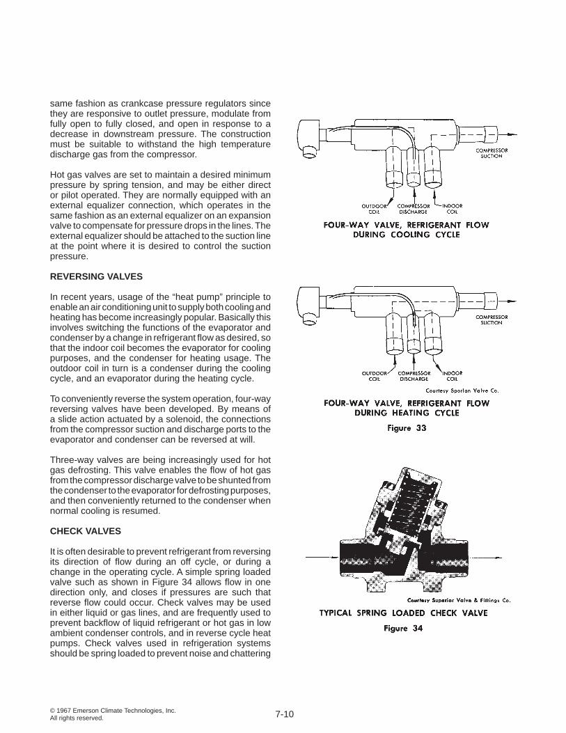
In recent years, usage of the “heat pump” principle to enable an air conditioning unit to supply both cooling and heating has become increasingly popular. Basically this involves switching the functions of the evaporator and condenser by a change in refrigerant fl ow as desired, so that the indoor coil becomes the evaporator for cooling purposes, and the condenser for heating usage. The outdoor coil in turn is a condenser during the cooling cycle, and an evaporator during the heating cycle.
To conveniently reverse the system operation, four-way reversing valves have been developed. By means of a slide action actuated by a solenoid, the connections from the compressor suction and discharge ports to the evaporator and condenser can be reversed at will.
Three-way valves are being increasingly used for hot gas defrosting. This valve enables the fl ow of hot gas from the compressor discharge valve to be shunted from the condenser to the evaporator for defrosting purposes, and then conveniently returned to the condenser when normal cooling is resumed.
CHECK VALVES
It is often desirable to prevent refrigerant from reversing its direction of fl ow during an off cycle, or during a change in the operating cycle. A simple spring loaded valve such as shown in Figure 34 allows fl ow in one direction only, and closes if pressures are such that reverse fl ow could occur. Check valves may be used in either liquid or gas lines, and are frequently used to prevent backfl ow of liquid refrigerant or hot gas in low ambient condenser controls, and in reverse cycle heat pumps. Check valves used in refrigeration systems should be spring loaded to prevent noise and chattering
7-10
© 1967 Emerson Climate Technologies, Inc.All rights reserved.
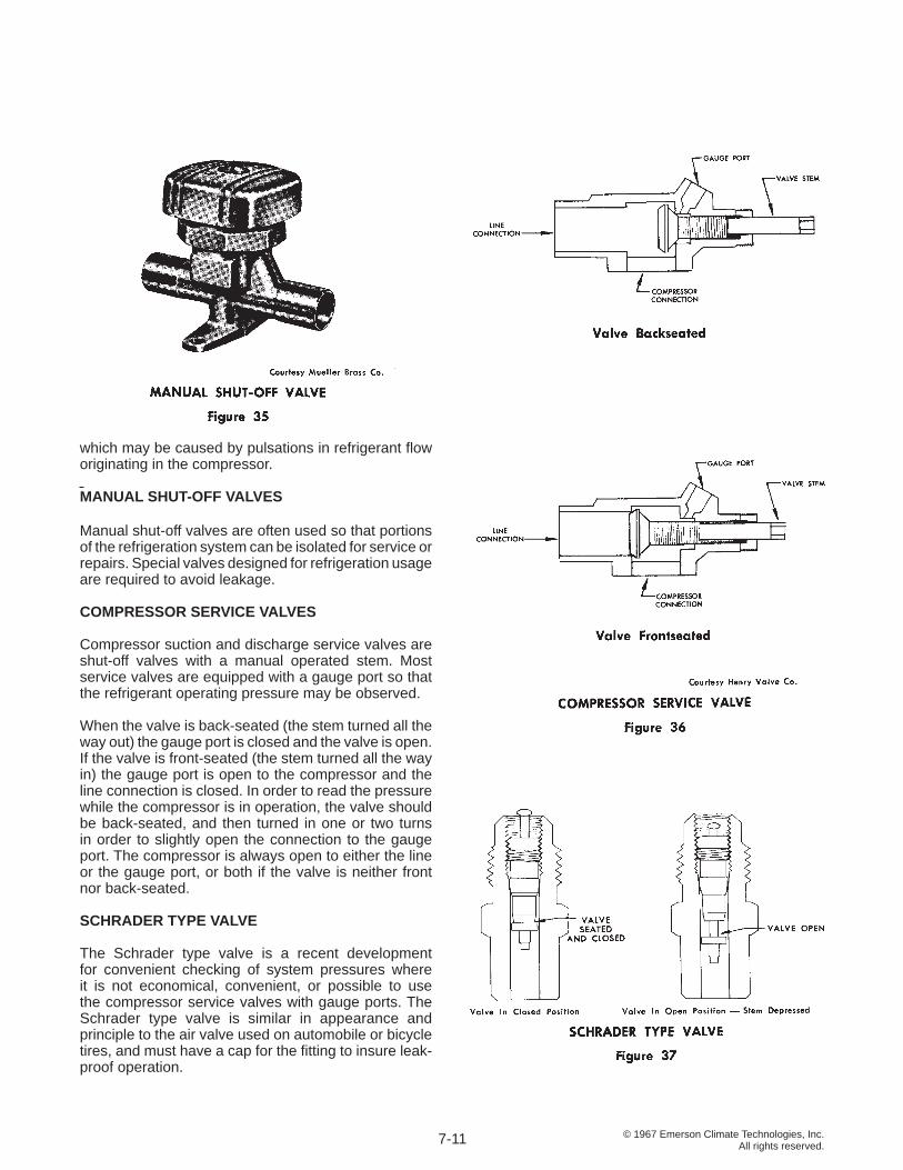
which may be caused by pulsations in refrigerant fl ow originating in the compressor. MANUAL SHUT-OFF VALVES
Manual shut-off valves are often used so that portions of the refrigeration system can be isolated for service or repairs. Special valves designed for refrigeration usage are required to avoid leakage.
COMPRESSOR SERVICE VALVES Compressor suction and discharge service valves are shut-off valves with a manual operated stem. Most service valves are equipped with a gauge port so that the refrigerant operating pressure may be observed.
When the valve is back-seated (the stem turned all the way out) the gauge port is closed and the valve is open. If the valve is front-seated (the stem turned all the way in) the gauge port is open to the compressor and the line connection is closed. In order to read the pressure while the compressor is in operation, the valve should be back-seated, and then turned in one or two turns in order to slightly open the connection to the gauge port. The compressor is always open to either the line or the gauge port, or both if the valve is neither front nor back-seated.
SCHRADER TYPE VALVE
The Schrader type valve is a recent development for convenient checking of system pressures where it is not economical, convenient, or possible to use the compressor service valves with gauge ports. The Schrader type valve is similar in appearance and principle to the air valve used on automobile or bicycle tires, and must have a cap for the fi tting to insure leak-proof operation.
7-11
© 1967 Emerson Climate Technologies, Inc.All rights reserved.
This type of valve enables checking of the system pressure, or charging refrigerant without disturbing the unit operation. An adaptor is necessary for the standard serviceman’s gauge or hose connection to fi t the Schrader type valve.
PRESSURE RELIEF VALVES
Safety relief valves are required by many local construction codes. Various types of relief valves are available, and the system requirement may be dictated by the local code requirement. Normally code requirements specify that the ultimate strength of the high side parts shall be a minimum of 5 times the discharge or rupture pressure of the relief valve, and that all condensing units with pressure vessels exceeding 3 cubic feet interval volume shall be protected by a pressure relief device. Discharge may be to the atmosphere, or it may be a discharge from the high pressure side of the system to the low pressure side.
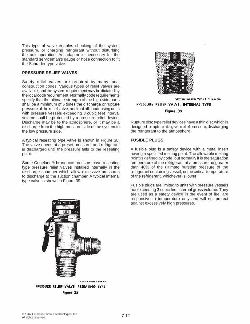
A typical reseating type valve is shown in Figure 38. The valve opens at a preset pressure, and refrigerant is discharged until the pressure falls to the reseating point.
Some Copeland® brand compressors have reseating type pressure relief valves installed internally in the discharge chamber which allow excessive pressures to discharge to the suction chamber. A typical internal type valve is shown in Figure 39.
Rupture disc type relief devices have a thin disc which is designed to rupture at a given relief pressure, discharging the refrigerant to the atmosphere.
FUSIBLE PLUGS
A fusible plug is a safety device with a metal insert having a specifi ed melting point. The allowable melting point is defi ned by code, but normally it is the saturation temperature of the refrigerant at a pressure no greater than 40% of the ultimate bursting pressure of the refrigerant containing vessel, or the critical temperature of the refrigerant, whichever is lower .
Fusible plugs are limited to units with pressure vessels not exceeding 3 cubic feet internal gross volume. They are used as a safety device in the event of fi re, are responsive to temperature only and will not protect against excessively high pressures.
7-12
© 1967 Emerson Climate Technologies, Inc.All rights reserved.
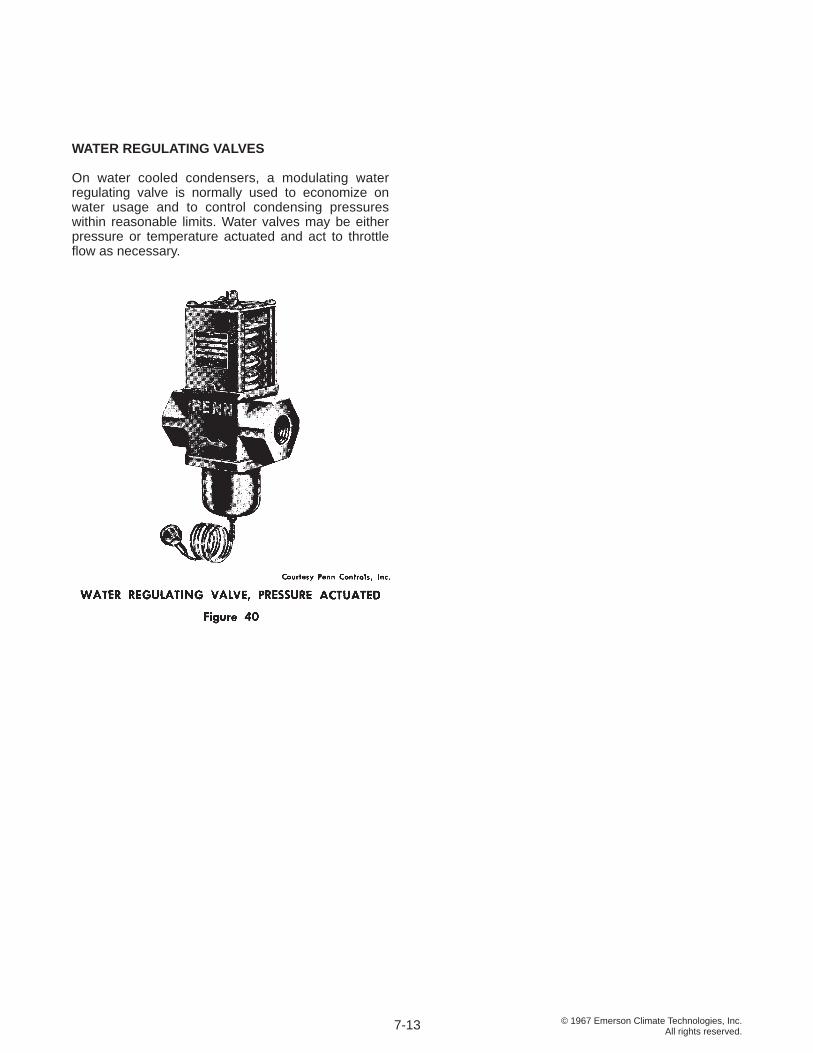
WATER REGULATING VALVES
On water cooled condensers, a modulating water regulating valve is normally used to economize on water usage and to control condensing pressures within reasonable limits. Water valves may be either pressure or temperature actuated and act to throttle fl ow as necessary.
7-13
© 1967 Emerson Climate Technologies, Inc.All rights reserved.
SECTION 8 CONTROL DEVICES, ELECTRICAL
Both electrical and pneumatic controls are widely used for air conditioning and refrigeration system control. Pneumatic controls are primarily used on large central systems, while electric controls are used on applications of all sizes. Since electric controls are used almost exclusively in the commercial refrigeration fi eld, this manual will cover only electric controls.
CONTROL DIFFERENTIAL
The basic function of most electrical control devices is to make or break an electric circuit which in turn controls a contactor, a solenoid coil, or some other functioning part of the system. Controls are available which may make or break a circuit on either a rise or fall in pressure or temperature. The type of action required depends on the function of the control and the medium being controlled.
The point at which a control closes a contact and makes a circuit is called the cut-in point. The point at which the control opens the switch and breaks the circuit is called the cut-out point. The difference between the cut-in and cut-out points is known as the differential.
A very small differential maintains close control but can cause short cycling of the compressor. A large differential will give a longer running cycle, but may result in fl uctuations in the pressure or temperature being controlled, so the fi nal operating differential must be a compromise.
The differential may be either fi xed or adjustable, depending on the construction of the control. Adjustment of controls varies depending on the type and the manufacturer. On some controls, both the cut-in and cut-out points may be set at the desired points. On many pressure controls, the differential can be adjusted, and this in turn may affect either the cut-in or the cut-out point.
LINE VOLTAGE AND LOW VOLTAGE CONTROLS
Line voltage controls are designed to operate on the same voltage as that supplied to the compressor. Both 110 and 220 volt controls are quite commonly used, and 440 volt controls are available but are seldom used due to the danger from high voltage at the wiring connections.
Local codes often require low voltage controls, and a control circuit transformer may be used to reduce line
voltage to the control circuit voltage, usually 24 volts.
LOW PRESSURE AND HIGH PRESSURE CONTROLS
A low pressure control is actuated by the refrigerant suction pressure, and normally is used to cycle the compressor for capacity control purposes, or as a low limit control. The low pressure control often is used as the only control on small systems which can tolerate some fl uctuations in the temperature to be maintained. The standard low pressure control makes on a rise in pressure, and breaks on a fall in pressure.
A high pressure control senses the compressor discharge pressure, and is normally used to stop the compressor in case of excessively high pressures. Since the allowable pressure limit varies with different refrigerants, the proper high pressure control for the refrigerant in the system must be used. A high pressure control makes on a fall in pressure and breaks on a rise in pressure. Either manual reset or automatic reset controls are available, the choice depending on the desired system operation.
Dual pressure controls are comprised of a low pressure and a high pressure control mounted in a single housing with a single switch operated by either control.
8-1
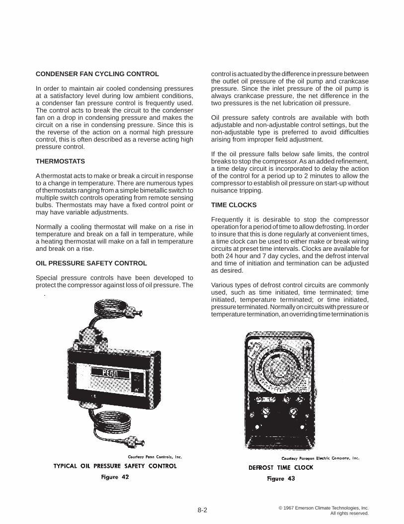
© 1967 Emerson Climate Technologies, Inc.All rights reserved.
CONDENSER FAN CYCLING CONTROL
In order to maintain air cooled condensing pressures at a satisfactory level during low ambient conditions, a condenser fan pressure control is frequently used. The control acts to break the circuit to the condenser fan on a drop in condensing pressure and makes the circuit on a rise in condensing pressure. Since this is the reverse of the action on a normal high pressure control, this is often described as a reverse acting high pressure control.
THERMOSTATS
A thermostat acts to make or break a circuit in response to a change in temperature. There are numerous types of thermostats ranging from a simple bimetallic switch to multiple switch controls operating from remote sensing bulbs. Thermostats may have a fi xed control point or may have variable adjustments.
Normally a cooling thermostat will make on a rise in temperature and break on a fall in temperature, while a heating thermostat will make on a fall in temperature and break on a rise.
OIL PRESSURE SAFETY CONTROL
Special pressure controls have been developed to protect the compressor against loss of oil pressure. The
control is actuated by the difference in pressure between the outlet oil pressure of the oil pump and crankcase pressure. Since the inlet pressure of the oil pump is always crankcase pressure, the net difference in the two pressures is the net lubrication oil pressure.
Oil pressure safety controls are available with both adjustable and non-adjustable control settings, but the non-adjustable type is preferred to avoid diffi culties arising from improper fi eld adjustment.
If the oil pressure falls below safe limits, the control breaks to stop the compressor. As an added refi nement, a time delay circuit is incorporated to delay the action of the control for a period up to 2 minutes to allow the compressor to establish oil pressure on start-up without nuisance tripping.
TIME CLOCKS
Frequently it is desirable to stop the compressor operation for a period of time to allow defrosting. In order to insure that this is done regularly at convenient times, a time clock can be used to either make or break wiring circuits at preset time intervals. Clocks are available for both 24 hour and 7 day cycles, and the defrost interval and time of initiation and termination can be adjusted as desired.
Various types of defrost control circuits are commonly used, such as time initiated, time terminated; time initiated, temperature terminated; or time initiated, pressure terminated. Normally on circuits with pressure or temperature termination, an overriding time termination is
8-2
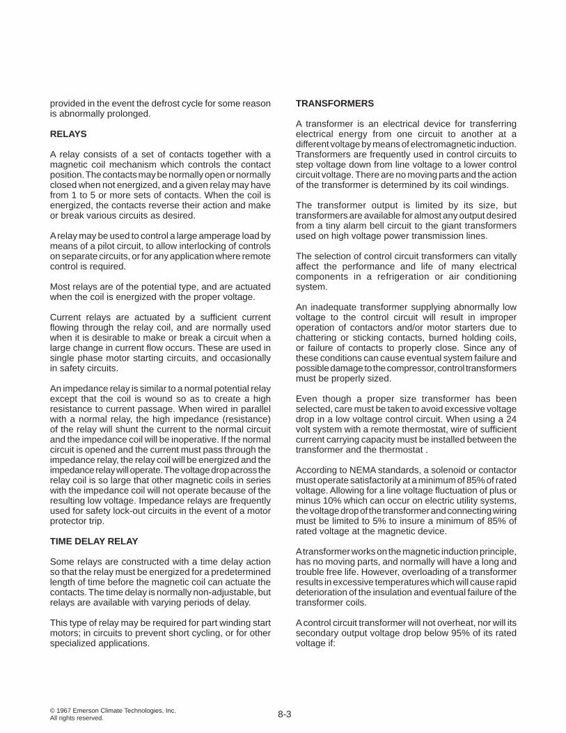
© 1967 Emerson Climate Technologies, Inc.All rights reserved.
provided in the event the defrost cycle for some reason is abnormally prolonged. RELAYS
A relay consists of a set of contacts together with a magnetic coil mechanism which controls the contact position. The contacts may be normally open or normally closed when not energized, and a given relay may have from 1 to 5 or more sets of contacts. When the coil is energized, the contacts reverse their action and make or break various circuits as desired.
A relay may be used to control a large amperage load by means of a pilot circuit, to allow interlocking of controls on separate circuits, or for any application where remote control is required.
Most relays are of the potential type, and are actuated when the coil is energized with the proper voltage.
Current relays are actuated by a suffi cient current fl owing through the relay coil, and are normally used when it is desirable to make or break a circuit when a large change in current fl ow occurs. These are used in single phase motor starting circuits, and occasionally in safety circuits.
An impedance relay is similar to a normal potential relay except that the coil is wound so as to create a high resistance to current passage. When wired in parallel with a normal relay, the high impedance (resistance) of the relay will shunt the current to the normal circuit and the impedance coil will be inoperative. If the normal circuit is opened and the current must pass through the impedance relay, the relay coil will be energized and the impedance relay will operate. The voltage drop across the relay coil is so large that other magnetic coils in series with the impedance coil will not operate because of the resulting low voltage. Impedance relays are frequently used for safety lock-out circuits in the event of a motor protector trip.
TIME DELAY RELAY
Some relays are constructed with a time delay action so that the relay must be energized for a predetermined length of time before the magnetic coil can actuate the contacts. The time delay is normally non-adjustable, but relays are available with varying periods of delay.
This type of relay may be required for part winding start motors; in circuits to prevent short cycling, or for other specialized applications.
TRANSFORMERS
A transformer is an electrical device for transferring electrical energy from one circuit to another at a different voltage by means of electromagnetic induction. Transformers are frequently used in control circuits to step voltage down from line voltage to a lower control circuit voltage. There are no moving parts and the action of the transformer is determined by its coil windings.
The transformer output is limited by its size, but transformers are available for almost any output desired from a tiny alarm bell circuit to the giant transformers used on high voltage power transmission lines.
The selection of control circuit transformers can vitally affect the performance and life of many electrical components in a refrigeration or air conditioning system.
An inadequate transformer supplying abnormally low voltage to the control circuit will result in improper operation of contactors and/or motor starters due to chattering or sticking contacts, burned holding coils, or failure of contacts to properly close. Since any of these conditions can cause eventual system failure and possible damage to the compressor, control transformers must be properly sized.
Even though a proper size transformer has been selected, care must be taken to avoid excessive voltage drop in a low voltage control circuit. When using a 24 volt system with a remote thermostat, wire of suffi cient current carrying capacity must be installed between the transformer and the thermostat .
According to NEMA standards, a solenoid or contactor must operate satisfactorily at a minimum of 85% of rated voltage. Allowing for a line voltage fl uctuation of plus or minus 10% which can occur on electric utility systems, the voltage drop of the transformer and connecting wiring must be limited to 5% to insure a minimum of 85% of rated voltage at the magnetic device.
A transformer works on the magnetic induction principle, has no moving parts, and normally will have a long and trouble free life. However, overloading of a transformer results in excessive temperatures which will cause rapid deterioration of the insulation and eventual failure of the transformer coils.
A control circuit transformer will not overheat, nor will its secondary output voltage drop below 95% of its rated voltage if:
8-3
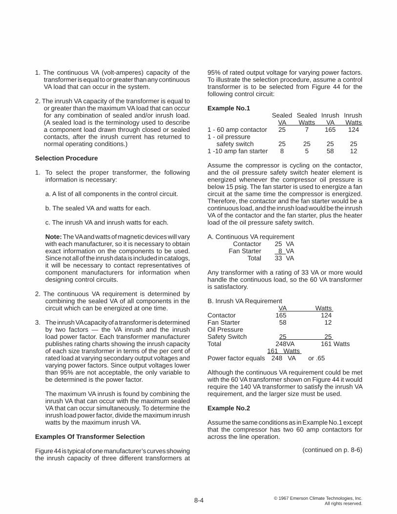
© 1967 Emerson Climate Technologies, Inc.All rights reserved.
1. The continuous VA (volt-amperes) capacity of the transformer is equal to or greater than any continuous VA load that can occur in the system.
2. The inrush VA capacity of the transformer is equal to or greater than the maximum VA load that can occur for any combination of sealed and/or inrush load. (A sealed load is the terminology used to describe a component load drawn through closed or sealed contacts, after the inrush current has returned to normal operating conditions.)
Selection Procedure
1. To select the proper transformer, the following information is necessary:
a. A list of all components in the control circuit.
b. The sealed VA and watts for each.
c. The inrush VA and inrush watts for each.
Note: The VA and watts of magnetic devices will vary with each manufacturer, so it is necessary to obtain exact information on the components to be used. Since not all of the inrush data is included in catalogs, it will be necessary to contact representatives of component manufacturers for information when designing control circuits.
2. The continuous VA requirement is determined by combining the sealed VA of all components in the circuit which can be energized at one time.
3. The inrush VA capacity of a transformer is determined by two factors — the VA inrush and the inrush load power factor. Each transformer manufacturer publishes rating charts showing the inrush capacity of each size transformer in terms of the per cent of rated load at varying secondary output voltages and varying power factors. Since output voltages lower than 95% are not acceptable, the only variable to be determined is the power factor.
The maximum VA inrush is found by combining the inrush VA that can occur with the maximum sealed VA that can occur simultaneously. To determine the inrush load power factor, divide the maximum inrush watts by the maximum inrush VA.
Examples Of Transformer Selection
Figure 44 is typical of one manufacturer’s curves showing the inrush capacity of three different transformers at
95% of rated output voltage for varying power factors. To illustrate the selection procedure, assume a control transformer is to be selected from Figure 44 for the following control circuit:
Example No.1 Sealed Sealed Inrush Inrush VA Watts VA Watts 1 - 60 amp contactor 25 7 165 124 1 - oil pressure safety switch 25 25 25 25 1 -10 amp fan starter 8 5 58 12
Assume the compressor is cycling on the contactor, and the oil pressure safety switch heater element is energized whenever the compressor oil pressure is below 15 psig. The fan starter is used to energize a fan circuit at the same time the compressor is energized. Therefore, the contactor and the fan starter would be a continuous load, and the inrush load would be the inrush VA of the contactor and the fan starter, plus the heater load of the oil pressure safety switch. A. Continuous VA requirement Contactor 25 VA Fan Starter 8 VA Total 33 VA
Any transformer with a rating of 33 VA or more would handle the continuous load, so the 60 VA transformer is satisfactory.
B. Inrush VA Requirement VA Watts Contactor 165 124 Fan Starter 58 12 Oil Pressure Safety Switch 25 25 Total 248VA 161 Watts 161 Watts Power factor equals 248 VA or .65
Although the continuous VA requirement could be met with the 60 VA transformer shown on Figure 44 it would require the 140 VA transformer to satisfy the inrush VA requirement, and the larger size must be used.
Example No.2
Assume the same conditions as in Example No.1 except that the compressor has two 60 amp contactors for across the line operation.
8-4
(continued on p. 8-6)
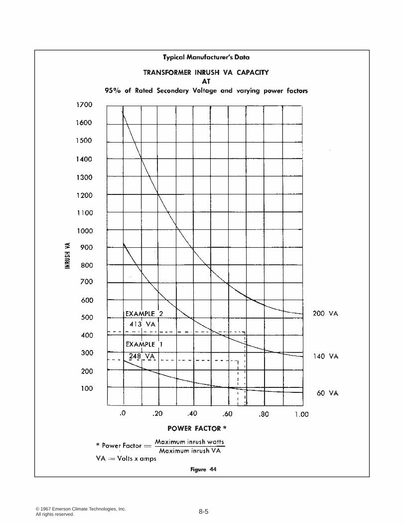
© 1967 Emerson Climate Technologies, Inc.All rights reserved. 8-5
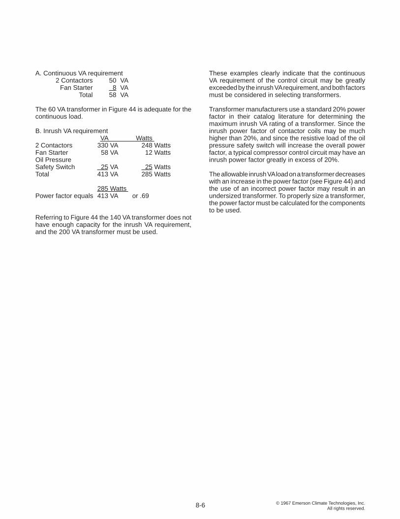
© 1967 Emerson Climate Technologies, Inc.All rights reserved.
A. Continuous VA requirement 2 Contactors 50 VA Fan Starter 8 VA Total 58 VA
The 60 VA transformer in Figure 44 is adequate for the continuous load.
B. Inrush VA requirement VA Watts 2 Contactors 330 VA 248 Watts Fan Starter 58 VA 12 Watts Oil Pressure Safety Switch 25 VA 25 Watts Total 413 VA 285 Watts
285 Watts Power factor equals 413 VA or .69
Referring to Figure 44 the 140 VA transformer does not have enough capacity for the inrush VA requirement, and the 200 VA transformer must be used.
These examples clearly indicate that the continuous VA requirement of the control circuit may be greatly exceeded by the inrush VA requirement, and both factors must be considered in selecting transformers.
Transformer manufacturers use a standard 20% power factor in their catalog literature for determining the maximum inrush VA rating of a transformer. Since the inrush power factor of contactor coils may be much higher than 20%, and since the resistive load of the oil pressure safety switch will increase the overall power factor, a typical compressor control circuit may have an inrush power factor greatly in excess of 20%. The allowable inrush VA load on a transformer decreases with an increase in the power factor (see Figure 44) and the use of an incorrect power factor may result in an undersized transformer. To properly size a transformer, the power factor must be calculated for the components to be used.
8-6
© 1967 Emerson Climate Technologies, Inc.All rights reserved.
SECTION 9 MOTORS
Electric motors are used as the power source on the great majority of refrigeration compressors, and practically all are now alternating current (A. C.) motors. The following discussion is limited to those motors of interest for driving refrigeration compressors.
Nearly all motors used for refrigeration applications are induction motors, the name coming from the fact that the current in the moving part of the motor is induced, the moving component having no connection to the source of current. The stationary part of an induction motor is called the stator, and the moving part the rotor. The stator windings are connected to the power source, while the rotor is mounted on the motor shaft, the rotation of the rotor providing the motor driving power source.
MOTOR TEMPERATURE
The fi rst law of thermodynamics stated that energy cannot be either created or destroyed, but may be converted from one form into another. The motor receives electrical energy from the power source, but because of friction and effi ciency losses, only a part of this input energy can be turned into mechanical output energy. The balance of the input energy is converted to heat energy, and unless this heat is dissipated, the temperature within the motor windings will rise until the insulation is destroyed. If a motor is kept free from contamination and physical damage, heat is practically the only enemy that can damage the windings.
The amount of heat produced in the motor depends both on the load and on motor effi ciency. As the load is increased, the electrical energy input to the motor increases. The percentage of the power input converted to heat in the motor depends on motor effi ciency, decreasing with an increase in effi ciency, and increasing as effi ciency decreases.
The temperature level, which a motor can tolerate, depends largely on the type of motor insulation and the basic motor design, but the actual motor life is determined by the operating conditions to which it is subjected during use. If operated in a proper environment, at loads within its design capabilities, a well designed motor should have an indefi nite life. Continuous overloading of a motor resulting in consistently high operating temperatures will materially shorten its life.
OPEN TYPE MOTORS AND BELT DRIVES
Open type motors may be used for compressor drive with either a belt drive or a direct drive arrangement, but with the continued development of hermetic and accessible-hermetic motor-compressor design, the use of open type motors has declined rapidly. Open type motors for compressor drives should be selected conservatively since open type motors do not have the generous overloading safety factor found in most motors used in hermetic and accessible hermetic compressors.
V-belts are made in several different industry classifi cations, which have been standardized for interchangeability. For refrigeration use, fractional horsepower industrial belts and conventional industrial belts are the two types commonly used. The fractional horsepower belts are more fl exible and are well adapted to small radius drives in the smaller horsepower range.
The conventional industrial belts have a higher horsepower rating for heavier loads. Fractional horsepower “4L” and conventional “A” belts have a comparable cross section and may be used on the same size pulley, while fractional horsepower “5L” and conventional “B” belts are similarly interchangeable.
For belt driven compressors, the compressor speed is determined by the size of the motor pulley, since the compressor pulley (fl ywheel) is normally fi xed. The relative speeds of the motor and compressor are in direct relation to the diameter of the motor pulley and the compressor fl ywheel, but for accurate calculation, the pitch diameter of the pulley must be used rather than the outside pulley diameter (O. D.). The pitch diameter makes allowance for the fact that the V-belt rides partially inside the pulley O. D. For drives using “A” and “4L” section belts, the pitch diameter may be taken as pulley O. D. less 1/4”, and for “B” and “5L” section belt drives, pulley O. D. less 3/8”.
9-1
© 1967 Emerson Climate Technologies, Inc.All rights reserved.
The desired pulley size or the resulting compressor speed may then be calculated from the following relation:
(Motor Speed, RPM) x (Pitch Diameter, Motor Pulley, In.) Compressor Speed, RPM = (Pitch Diameter, Compressor Pulley, In.)
(Compressor Speed, RPM) x (Pitch Dia., Compressor Pulley, In.) Pitch Diameter, Motor Pulley, In. = (Motor Speed, RPM)
For example, to fi nd the motor pulley diameter required when a 1750 RPM motor is to be used to drive a compressor having an 8” pitch diameter compressor pulley, when the desired compressor speed is 500 RPM, proceed as follows:
500 RPM Com. Speed x 8” P. D., Comp. Pulley P.D., Motor Pulley = 1750 RPM, Motor Speed
= 500 x 8 1750 = Approximately 2 1/4 inches P. D. For an “A” belt drive Motor Pulley O. D. = 2 1/4 inches P.D. + 1/4 inch = 2 1/2 inches O.D.
For a “B” belt drive Motor Pulley O. D. = 2 1/4 inches P.D. + 3/8 inch = 2 5/8 inches O.D.
HERMETIC MOTORS
In hermetic and accessible-hermetic motor-compressors, the motor is mounted directly on the compressor crankshaft, and is hermetically sealed within the compressor body. Aside from the economies inherent in this type of construction, the greatest advantage is that the motor can be cooled by a variety of means, such as air, water, or refrigerant vapor. Sealing the motor in the compressor body eliminates the troublesome problem of sealing the crankshaft so that the power may be transmitted without refrigerant leaks. By designing a motor for the specifi c application, and controlling motor temperature closely, a motor may be matched to a given load with the result that the motor output can be utilized at its maximum capability, while maintaining a generous safety factor considerably above that available with standard open type motors.
NAMEPLATE AMPERAGE
On open-type motors standard NEMA horsepower ratings are used to identify a motor’s power output capability. Because of industry practice, this nominal horsepower classifi cation has carried over into hermetic motor identifi cation, but it may be misleading when applied to this type of motor. With controlled cooling and motor protection sized for the exact load, a hermetic motor may be operated much closer to its maximum ability, so a given motor may be capable of much greater power output as a hermetic motor than an equivalent open motor. The amperage draw and watts of power required are much better indicators of hermetic motor operation.
Each Copeland® brand motor-compressor carries on its nameplate ratings for both locked rotor and full load amperes. The designation full load amperage persists because of long industry precedent, but in reality a much better term is nameplate amperage. On all welded compressors, on all new motors now being developed for Copelametic® compressors, and on most of the motors developed with inherent protection or internal thermostats, nameplate amperage has been arbitrarily established as 80% of the current drawn when the motor protector trips. The 80% fi gure is derived from standard industry practice of many years’ standing in sizing motor protective devices at 125 % of the current drawn at rated load conditions.
In order for the motor to meet Emerson Climate Technologies, Inc. standards, the maximum allowable current must be beyond the prescribed operating limits of the compressor, and is determined during qualifi cation tests by operating the compressor at established maximum load conditions and lowering the supply voltage until the protector trip point is reached. Use of the standard 80% factor enables the service and installation engineer to safely size wiring, contactors, or other external line protective devices at 125% of the nameplate rating, since the motor-compressor protector will not allow the amperage to exceed this fi gure.
In most instances, the motor-compressor is capable of performing at nominal rating conditions at less than rated nameplate amperage. A given motor frequently is used in various compressor models for air-cooled,
9-2
© 1967 Emerson Climate Technologies, Inc.All rights reserved.
suction-cooled, water-cooled, high temperature, medium temperature, low temperature, R-12, R-22, or R-502 applications as required. Obviously on many applications there will be a greater safety factor than on others.
This does not mean that every compressor may be operated continuously at a load greatly in excess of its nameplate rating without fear of failure. Motor amperage is only one factor in determining a compressor’s operating limitations. Discharge pressure and temperatures, motor cooling, and torque requirements are equally critical. Safe operating limits have been established for each compressor, and are published on compressor specifi cation sheets.
VOLTAGE AND FREQUENCY
Although electric energy distributed in the United States is 60 cycle, distribution voltages are not standardized. Single phase voltages may be 115, 208, 220, 230, or 240, and most utilities reserve the right to vary the supply voltage plus or minus 10% from the nominal rating. Three phase voltage may be 208, 220, 240, 440, 460, or 480, again plus or minus 10%. Unless motors are specifi cally designed for the voltage range in which they are operated, overheating may result.
Most motors may be operated at the voltage on the motor nameplate, plus or minus 10% without danger of overheating, but in order to allow more fl exibility of operation, extended voltage range motors are now being developed where the usage warrants this action. For example, a three phase motor nameplated 208/240 volts is satisfactory for operation from 187 volts to 264 volts, and a three phase motor nameplated 440/480 volts may be operated from 396 volts to 528 volts.
In many parts of the world, the electrical power supply is 50 cycle rather that 60 cycle. If both voltage and frequency supplied to a motor vary at the same rate, operation of a given motor at the lower frequency condition within narrow limits is satisfactory in some cases. For example, a 440 volt, 3 phase, 60 cycle motor will operate satisfactorily on 380 volt, 3 phase, 50 cycle power supply.
However, in some 50 cycle applications, the relationship between voltage and frequency is such that standard 60 cycle motors cannot be used unless the motor characteristics are suitable for 50 cycle operation, and this can be determined only by test. On most single phase 50 cycle applications, specially wound 50 cycle motors are required.
THREE PHASE MOTORS
Three phase motors are wound with 3 separate windings or phases. Each of the windings is 120° out of phase with the other windings, which results in a very high starting torque motor requiring no supplemental mechanisms or devices for starting. The direction of rotation of the motor may be changed by reversing any two line connections.
Because three phase motors can utilize smaller wire sizes and therefore are smaller, they are used on almost all applications larger than 5 HP, and if three phase power is available, are frequently preferred for any load larger than fractional horsepower applications.
SINGLE PHASE MOTORS
A single phase motor has but one running winding or phase, and basically is not a self starting motor. Once started, it will run as a pure induction motor. In order to provide starting torque, a second winding called the starting winding is provided, which normally has greater resistance than the running winding. The different variations of single phase motors are primarily due to the different starting arrangements used.
If the start winding remains in the circuit during operation it would be damaged by excessive heat. Therefore, the starting winding is removed from the circuit as the motor approaches rated speed by either a potential relay, a current relay, or a centrifugal switch.
A current relay is normally open when de-energized, and the coil is wound so that the contacts will close when starting current is being drawn by the motor, but will drop out when the current approaches normal full load conditions. Therefore, the current relay is closed only during the starting cycle.
A potential relay is normally closed when de-energized, and the coil is designed to open the contacts only when suffi cient voltage is generated by the start winding. Since the voltage or back-EMF generated by the start winding is proportional to the motor speed, the relay will open only when the motor has started and is approaching normal running speed. The illustrations show the schematic wiring with the motor in operation so the potential relay is in the energized position.
SPLIT PHASE MOTORS
On a split phase motor, the running winding and start winding are in parallel, and are spaced 90° apart. The
9-3
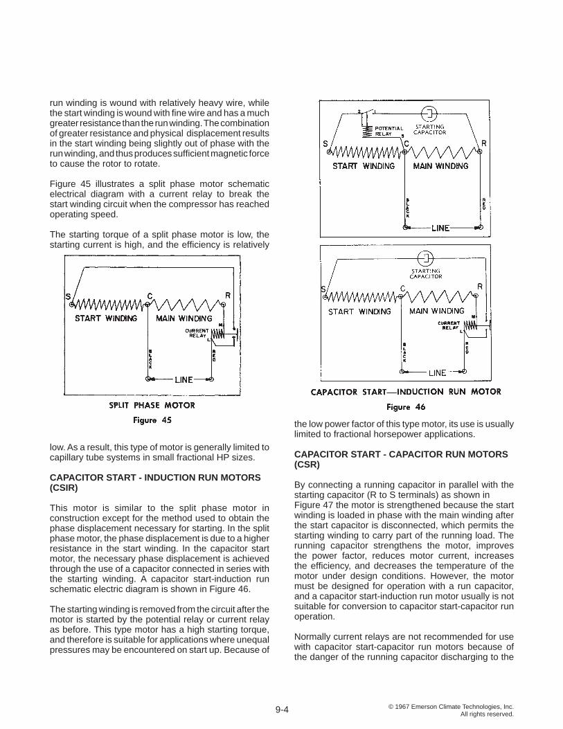
© 1967 Emerson Climate Technologies, Inc.All rights reserved.
run winding is wound with relatively heavy wire, while the start winding is wound with fi ne wire and has a much greater resistance than the run winding. The combination of greater resistance and physical displacement results in the start winding being slightly out of phase with the run winding, and thus produces suffi cient magnetic force to cause the rotor to rotate.
Figure 45 illustrates a split phase motor schematic electrical diagram with a current relay to break the start winding circuit when the compressor has reached operating speed.
The starting torque of a split phase motor is low, the starting current is high, and the effi ciency is relatively
low. As a result, this type of motor is generally limited to capillary tube systems in small fractional HP sizes.
CAPACITOR START - INDUCTION RUN MOTORS (CSIR)
This motor is similar to the split phase motor in construction except for the method used to obtain the phase displacement necessary for starting. In the split phase motor, the phase displacement is due to a higher resistance in the start winding. In the capacitor start motor, the necessary phase displacement is achieved through the use of a capacitor connected in series with the starting winding. A capacitor start-induction run schematic electric diagram is shown in Figure 46.
The starting winding is removed from the circuit after the motor is started by the potential relay or current relay as before. This type motor has a high starting torque, and therefore is suitable for applications where unequal pressures may be encountered on start up. Because of
the low power factor of this type motor, its use is usually limited to fractional horsepower applications.
CAPACITOR START - CAPACITOR RUN MOTORS (CSR)
By connecting a running capacitor in parallel with the starting capacitor (R to S terminals) as shown in Figure 47 the motor is strengthened because the start winding is loaded in phase with the main winding after the start capacitor is disconnected, which permits the starting winding to carry part of the running load. The running capacitor strengthens the motor, improves the power factor, reduces motor current, increases the effi ciency, and decreases the temperature of the motor under design conditions. However, the motor must be designed for operation with a run capacitor, and a capacitor start-induction run motor usually is not suitable for conversion to capacitor start-capacitor run operation.
Normally current relays are not recommended for use with capacitor start-capacitor run motors because of the danger of the running capacitor discharging to the
9-4
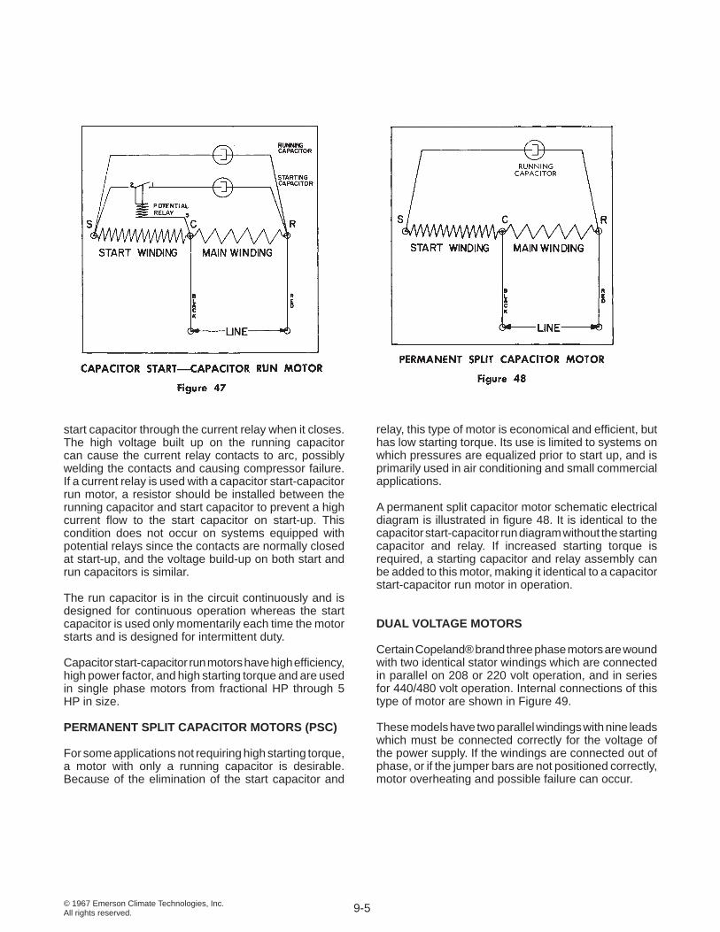
© 1967 Emerson Climate Technologies, Inc.All rights reserved.
start capacitor through the current relay when it closes. The high voltage built up on the running capacitor can cause the current relay contacts to arc, possibly welding the contacts and causing compressor failure. If a current relay is used with a capacitor start-capacitor run motor, a resistor should be installed between the running capacitor and start capacitor to prevent a high current fl ow to the start capacitor on start-up. This condition does not occur on systems equipped with potential relays since the contacts are normally closed at start-up, and the voltage build-up on both start and run capacitors is similar.
The run capacitor is in the circuit continuously and is designed for continuous operation whereas the start capacitor is used only momentarily each time the motor starts and is designed for intermittent duty.
Capacitor start-capacitor run motors have high effi ciency, high power factor, and high starting torque and are used in single phase motors from fractional HP through 5 HP in size.
PERMANENT SPLIT CAPACITOR MOTORS (PSC)
For some applications not requiring high starting torque, a motor with only a running capacitor is desirable. Because of the elimination of the start capacitor and
relay, this type of motor is economical and effi cient, but has low starting torque. Its use is limited to systems on which pressures are equalized prior to start up, and is primarily used in air conditioning and small commercial applications.
A permanent split capacitor motor schematic electrical diagram is illustrated in fi gure 48. It is identical to the capacitor start-capacitor run diagram without the starting capacitor and relay. If increased starting torque is required, a starting capacitor and relay assembly can be added to this motor, making it identical to a capacitor start-capacitor run motor in operation.
DUAL VOLTAGE MOTORS
Certain Copeland® brand three phase motors are wound with two identical stator windings which are connected in parallel on 208 or 220 volt operation, and in series for 440/480 volt operation. Internal connections of this type of motor are shown in Figure 49.
These models have two parallel windings with nine leads which must be connected correctly for the voltage of the power supply. If the windings are connected out of phase, or if the jumper bars are not positioned correctly, motor overheating and possible failure can occur.
9-5
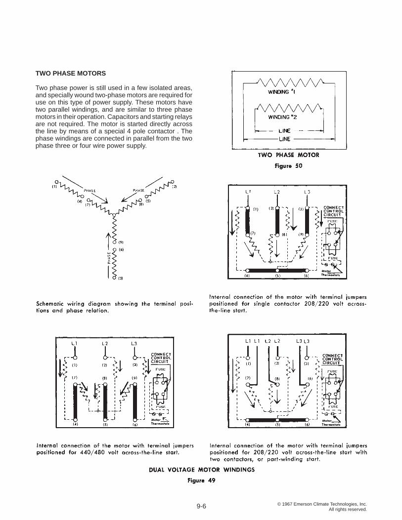
© 1967 Emerson Climate Technologies, Inc.All rights reserved.
TWO PHASE MOTORS
Two phase power is still used in a few isolated areas, and specially wound two-phase motors are required for use on this type of power supply. These motors have two parallel windings, and are similar to three phase motors in their operation. Capacitors and starting relays are not required. The motor is started directly across the line by means of a special 4 pole contactor . The phase windings are connected in parallel from the two phase three or four wire power supply.
9-6
© 1967 Emerson Climate Technologies, Inc.All rights reserved.
SECTION 10 STARTING EQUIPMENT AND MOTOR PROTECTORS
Since hermetic motors must operate under a wide range of operating conditions, and vary in size from fractional horsepower to 35 HP and larger, a wide variety of starting equipment is used.
CONTACTORS AND STARTERS
A contactor is a load current carrying device, which makes and breaks to start and stop the compressor motor. A starter is merely a contactor with motor protective devices mounted in a common enclosure.
On single phase motors up to 3 HP in size, the motor current is often low enough to be handled by the contacts in the low pressure control or thermostat, and no separate contactor is required. As the motor size increases, the amperage draw increases beyond the range of small control apparatus, and the motor current must be handled through the contacts of a starter or contactor, while the control makes and breaks a pilot circuit which energizes the coil of the contactor .
For motor-compressors whose power requirements are such that contactors are required, it is essential that the contactors used are adequately sized for the attached load. The rating of the contactor for both full load amperes and locked rotor amperes must be greater than the nameplate rating of the motor-compressor plus the nameplate rating of any fans or other accessories also operated through the contactor .
NEMA general purpose type contactors are built for the most severe industrial usage, and are designed for a minimum life of 2,000,000 cycles. Because they must be adaptable to any usage, general purpose contactors have a large safety factor, and as a result are both large and costly. For refrigeration and air conditioning applications, a life of 250,000 cycles is entirely adequate, so the physical construction can be lighter, and the cost of the contactor correspondingly less.
To meet the specifi c needs of the refrigeration and air conditioning industry, electrical equipment manufacturers have developed defi nite purpose contactors. These contactors are rated in amperes, and when selected properly for the load, are smaller and more economical than the general purpose contactor. Since compressor contactors are frequently subjected to quick recycling, the contacts must be large enough for satisfactory heat dissipation in order to prevent contactor overheating.
Overheating of the contacts may cause sticking and single phasing, and can cause a motor failure even though the motor overload protectors trip and open the control circuit.
In order to insure that defi nite purpose contactors are properly applied to Copeland® brand motor-compressors with pilot circuit protection, the contactor must meet Emerson Climate Technologies, Inc. minimum performance requirements.
CAPACITORS
An electrical capacitor is a device which stores electrical energy. They are used in electric motors primarily to displace the phase of the current passing through the start winding. While a detailed study of electrical theory is beyond the scope of this manual, capacitors in a motor circuit provide starting torque, improve running characteristics and effi ciency, and improve the power factor.
The amount of electrical energy a capacitor will hold depends on the voltage applied. If the voltage is increased, the amount of electrical energy stored in the capacitor is increased. The capacity of a capacitor is expressed in microfarads (MFD) and is dependent on the size and construction of the capacitor.
The voltage rating of a capacitor indicates the nominal voltage at which it is designed to operate. Use of a capacitor at voltages below its rating will do no harm. Run capacitors must not be subjected to voltages exceeding 110% of the nominal rating, and start capacitors must not be subjected to voltages exceeding 130% of the nominal rating. The voltage to which a capacitor is subjected is not line voltage, but is a much higher potential (often called electromotive force or back EMF) which is generated in the start winding. On a typical 230 volt motor, the generated voltage may be as high as 450 volts, and is determined by the start winding characteristics, the compressor speed, and the applied voltage.
Capacitors, either start or run, can be connected either in series or parallel to provide the desired characteristics if the voltage and MFD are properly selected. When two capacitors having the same MFD rating are connected in series, the resulting total capacitance will be one half the rated capacitance of a single capacitor. The formula for determining capacitance (MFD) when capacitors are connected in series is as follows:
10-1
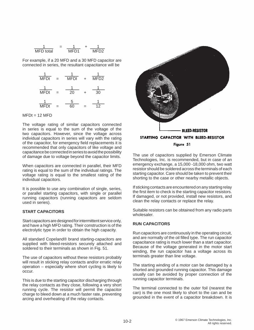
© 1967 Emerson Climate Technologies, Inc.All rights reserved.
1 = 1 + 1 MFD total MFD1 MFD2 For example, if a 20 MFD and a 30 MFD capacitor are connected in series, the resultant capacitance will be
1 1 1 MFDt = MFDl + MFD2
1 1 1 MFDt = 20 + 30
1 5 1 MFDt = 60 = 12
MFDt = 12 MFD
The voltage rating of similar capacitors connected in series is equal to the sum of the voltage of the two capacitors. However, since the voltage across individual capacitors in series will vary with the rating of the capacitor, for emergency fi eld replacements it is recommended that only capacitors of like voltage and capacitance be connected in series to avoid the possibility of damage due to voltage beyond the capacitor limits.
When capacitors are connected in parallel, their MFD rating is equal to the sum of the individual ratings. The voltage rating is equal to the smallest rating of the individual capacitors.
It is possible to use any combination of single, series, or parallel starting capacitors, with single or parallel running capacitors (running capacitors are seldom used in series).
START CAPACITORS
Start capacitors are designed for intermittent service only, and have a high MFD rating. Their construction is of the electrolytic type in order to obtain the high capacity.
All standard Copeland® brand starting-capacitors are supplied with bleed-resistors securely attached and soldered to their terminals as shown in Fig. 51.
The use of capacitors without these resistors probably will result in sticking relay contacts and/or erratic relay operation – especially where short cycling is likely to occur.
This is due to the starting capacitor discharging through the relay contacts as they close, following a very short running cycle. The resistor will permit the capacitor charge to bleed down at a much faster rate, preventing arcing and overheating of the relay contacts.
The use of capacitors supplied by Emerson Climate Technologies, Inc. is recommended, but in case of an emergency exchange, a 15,000 -18,000 ohm, two watt resistor should be soldered across the terminals of each starting capacitor. Care should be taken to prevent their shorting to the case or other nearby metallic objects.
If sticking contacts are encountered on any starting relay the fi rst item to check is the starting capacitor resistors. If damaged, or not provided, install new resistors, and clean the relay contacts or replace the relay.
Suitable resistors can be obtained from any radio parts wholesaler.
RUN CAPACITORS
Run capacitors are continuously in the operating circuit, and are normally of the oil fi lled type. The run capacitor capacitance rating is much lower than a start capacitor. Because of the voltage generated in the motor start winding, the run capacitor has a voltage across its terminals greater than line voltage.
The starting winding of a motor can be damaged by a shorted and grounded running capacitor. This damage usually can be avoided by proper connection of the running capacitor terminals.
The terminal connected to the outer foil (nearest the can) is the one most likely to short to the can and be grounded in the event of a capacitor breakdown. It is
10-2
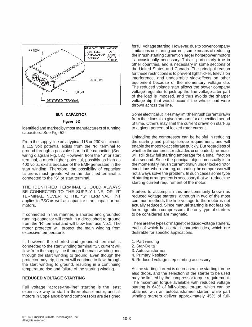
© 1967 Emerson Climate Technologies, Inc.All rights reserved.
identifi ed and marked by most manufacturers of running capacitors. See Fig. 52.
From the supply line on a typical 115 or 230 volt circuit, a 115 volt potential exists from the “R” terminal to ground through a possible short in the capacitor. (See wiring diagram Fig. 53.) However, from the “S” or start terminal, a much higher potential, possibly as high as 400 volts, exists because of the EMF generated in the start winding. Therefore, the possibility of capacitor failure is much greater when the identifi ed terminal is connected to the “S” or start terminal.
THE IDENTIFIED TERMINAL SHOULD ALWAYS BE CONNECTED TO THE SUPPLY LINE, OR “R” TERMINAL, NEVER TO THE “S” TERMINAL. This applies to PSC as well as capacitor-start, capacitor-run motors.
If connected in this manner, a shorted and grounded running-capacitor will result in a direct short to ground from the “R” terminal and will blow line fuse No.1. The motor protector will protect the main winding from excessive temperature.
If, however, the shorted and grounded terminal is connected to the start winding terminal “S”, current will fl ow from the supply line through the main winding and through the start winding to ground. Even though the protector may trip, current will continue to fl ow through the start winding to ground, resulting in a continuing temperature rise and failure of the starting winding.
REDUCED VOLTAGE STARTING
Full voltage “across-the-line” starting is the least expensive way to start a three-phase motor, and all motors in Copeland® brand compressors are designed
for full voltage starting. However, due to power company limitations on starting current, some means of reducing the inrush starting current on larger horsepower motors is occasionally necessary. This is particularly true in other countries, and is necessary in some sections of the United States and Canada. The principal reason for these restrictions is to prevent light fl icker, television interference, and undesirable side-effects on other equipment because of the momentary voltage dip. The reduced voltage start allows the power company voltage regulator to pick up the line voltage after part of the load is imposed, and thus avoids the sharper voltage dip that would occur if the whole load were thrown across the line.
Some electrical utilities may limit the inrush current drawn from their lines to a given amount for a specifi ed period of time. Others may limit the current drawn on start-up to a given percent of locked rotor current.
Unloading the compressor can be helpful in reducing the starting and pull-up torque requirement, and will enable the motor to accelerate quickly. But regardless of whether the compressor is loaded or unloaded, the motor will still draw full starting amperage for a small fraction of a second. Since the principal objection usually is to the momentary inrush current drawn under locked rotor conditions when starting, unloading the compressor will not always solve the problem. In such cases some type of starting arrangement is necessary that will reduce the starting current requirement of the motor.
Starters to accomplish this are commonly known as reduced voltage starters, although in two of the most common methods the line voltage to the motor is not actually reduced. Since manual starting is not feasible for refrigeration compressors, the only type of starters to be considered are magnetic.
There are fi ve types of magnetic reduced voltage starters, each of which has certain characteristics, which are desirable for specifi c applications.
1. Part winding 2. Star-Delta 3. Autotransformer 4. Primary Resistor 5. Reduced voltage step starting accessory
As the starting current is decreased, the starting torque also drops, and the selection of the starter to be used may be limited by the compressor torque requirement. The maximum torque available with reduced voltage starting is 64% of full-voltage torque, which can be obtained with an autotransformer starter, while part winding starters deliver approximately 45% of full-
10-3
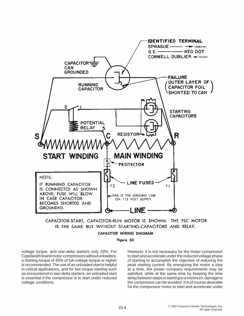
© 1967 Emerson Climate Technologies, Inc.All rights reserved.
voltage torque, and star-delta starters only 33%. For Copeland® brand motor-compressors without unloaders, a starting torque of 45% of full-voltage torque or higher is recommended. The use of an unloaded start is helpful in critical applications, and for low torque starting such as encountered in star-delta starters, an unloaded start is essential if the compressor is to start under reduced voltage conditions.
However, it is not necessary for the motor-compressor to start and accelerate under the reduced voltage phase of starting to accomplish the objective of reducing the peak starting current. By energizing the motor a step at a time, the power company requirements may be satisfi ed, while at the same time by keeping the time delay between steps in starting to a minimum, damage to the compressor can be avoided. It is of course desirable for the compressor motor to start and accelerate under
10-4
© 1967 Emerson Climate Technologies, Inc.All rights reserved.
reduced voltage starting conditions to realize the major benefi ts of this type of starting arrangement.
1. Part Winding Start
This is not a true reduced voltage start, but it accomplishes the same job - limiting inrush current - by utilizing only part of the motor windings. Since it uses both the start and run contactors to carry the motor current during operation, it costs less than the other types.
To utilize part winding start, the motor must have a dual winding. Copeland® brand 208/220/440 volt, 3 phase motors are wound with two identical stator windings which are connected in parallel on 208 or 220 volt operation. For part winding start, the fi rst step utilizes only one winding or 1/2 of the stator, and these motors may be used whenever part winding start is required on 208 or 220 volt power. Part winding start cannot be used on these motors when used on 440 volts, since the entire winding must be connected in series for 440 volt power .
Copelametic® model 4R and 6R compressors are currently available with dual wound motors, and some 4R and 6R models are available with specially wound motors for part winding start on 550 volts.
Basically all that is required for part winding start are two contactors, each capable of carrying the winding’s full load and locked rotor current requirement, with a time delay between the contactors. When the starter is energized, the fi rst magnetic contactor closes and puts half of the motor winding across the line. A preset time delay relay is energized at the same time, and at the completion of the timing cycle, the second magnetic contactor closes and puts the second half of the motor winding in parallel with the fi rst.
The normal Copeland® brand compressor motor protectors must be used. Where current sensing protectors are required, they must be installed in at least two phases of each contactor. Motors equipped with a Thermotector need no other external protection. To prevent tripping of the protectors during starting, the time delay between the fi rst and second contactor must be well within the protector’s tolerance for locked rotor conditions, and a time delay device having a time cycle setting of one second ± 10% is required.
The exact current and torque characteristics of a motor will vary with design. For Copeland® brand motor-compressors starting on one winding, the motor will draw approximately 65% of the normal across-the-line starting current, and produce approximately 45% of the normal starting torque. Under heavily loaded conditions,
it is possible that the motor may not start until the second winding is energized, or if it does start, it may not accelerate. An unloaded start may be desirable under extreme conditions.
On part winding start applications, occasionally an electrical starting noise or “growl” of short duration may be noticed. This occurs when the fi rst half winding starts the motor, but is unable to accelerate it beyond a few hundred rpm. As soon as the second winding is energized, the motor instantly accelerates, and the noise disappears. Since the time delay between windings is no greater than one second, the noise duration is very short.
The noise will vary with voltage, speed, pressure differential, motor horsepower, and will vary slightly from compressor to compressor. In addition, motors supplied by different sources may have slight differences in motor characteristics, and the resulting sound may be slightly different.
Occasionally service personnel mistake the starting noise for bearing drag. The starting noise is quite normal, will be more pronounced on larger motors, and does not harm the compressor In any way.
2. Star-Delta Starting
For star-delta starting (also referred to as wye-delta) a specially wound motor is required with both ends of each phase winding brought out to terminals. By means of contactors a motor designed for normal operation in delta is fi rst connected in star, and after a predetermined time delay, the star connection is changed to delta. This starting arrangement is relatively simple and inexpensive, and is widely used in Europe.
Recently three phase, 50 cycle motors have been developed for most Copeland® brand compressors 7½ HP and larger specially wound for star-delta starting. Leads were brought out from both ends of each phase so that the motors could be connected in either star or delta. Motors are available for star-delta start connections on either 380 volt, 50 cycle, 3 phase or 220 volt, 50 cycle, 3 phase circuits.
When a motor designed for delta operation is connected in star, the voltage across each phase is reduced to 58% of normal, and the motor develops 1/3 of the normal starting torque. The inrush current in star is 1/3 of normal inrush current in delta.
Star-delta starting is suitable for low torque starting duty only. To insure starting on the star connection, some means of pressure equalization across the compressor
10-5
(continued on p. 10-7)
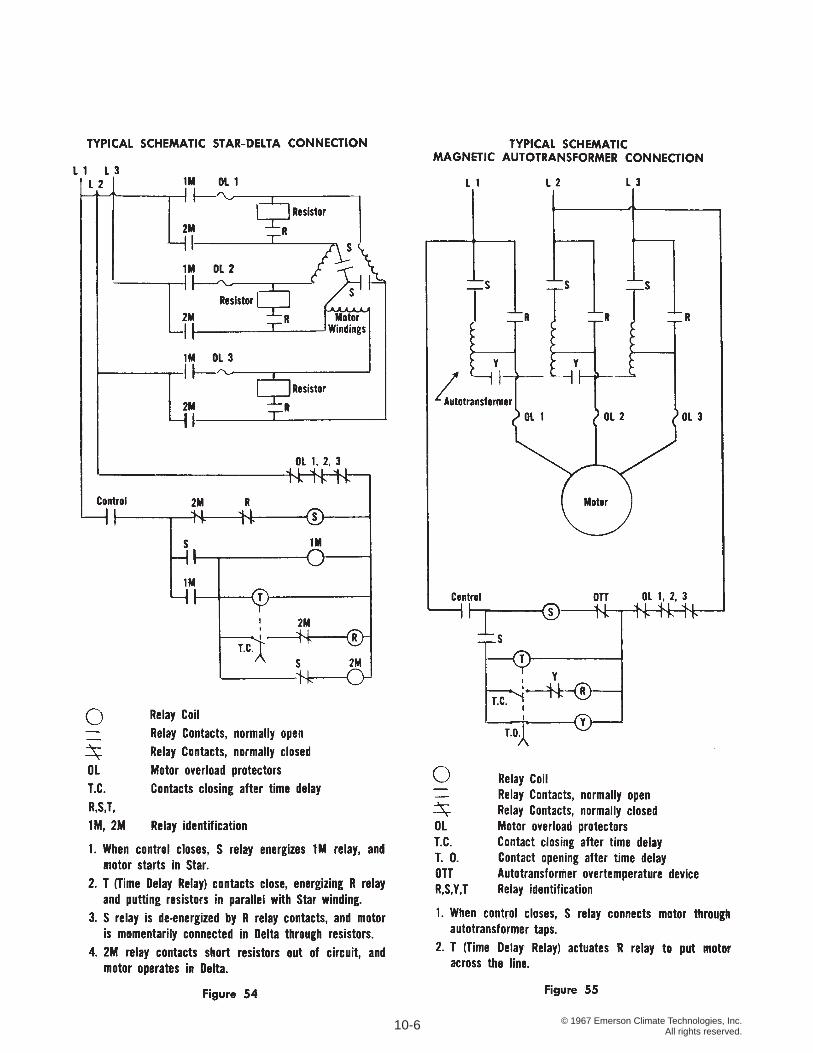
© 1967 Emerson Climate Technologies, Inc.All rights reserved.10-6
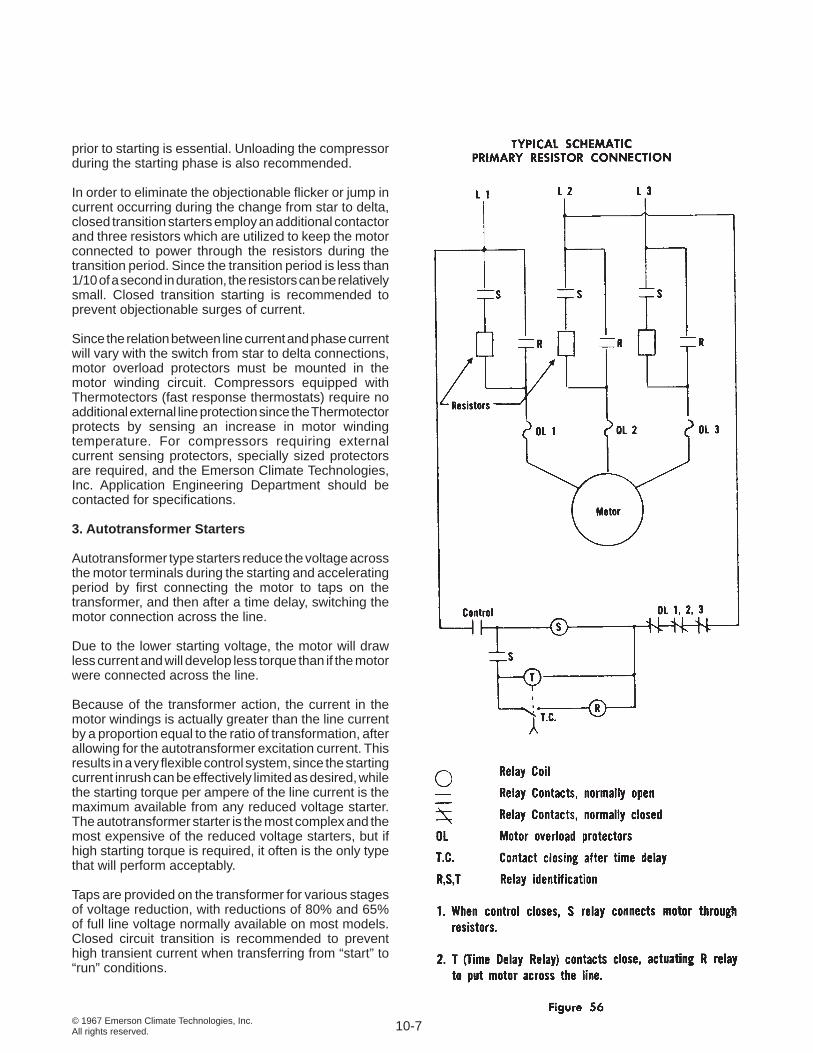
© 1967 Emerson Climate Technologies, Inc.All rights reserved.
prior to starting is essential. Unloading the compressor during the starting phase is also recommended.
In order to eliminate the objectionable fl icker or jump in current occurring during the change from star to delta, closed transition starters employ an additional contactor and three resistors which are utilized to keep the motor connected to power through the resistors during the transition period. Since the transition period is less than 1/10 of a second in duration, the resistors can be relatively small. Closed transition starting is recommended to prevent objectionable surges of current.
Since the relation between line current and phase current will vary with the switch from star to delta connections, motor overload protectors must be mounted in the motor winding circuit. Compressors equipped with Thermotectors (fast response thermostats) require no additional external line protection since the Thermotector protects by sensing an increase in motor winding temperature. For compressors requiring external current sensing protectors, specially sized protectors are required, and the Emerson Climate Technologies, Inc. Application Engineering Department should be contacted for specifi cations.
3. Autotransformer Starters
Autotransformer type starters reduce the voltage across the motor terminals during the starting and accelerating period by fi rst connecting the motor to taps on the transformer, and then after a time delay, switching the motor connection across the line.
Due to the lower starting voltage, the motor will draw less current and will develop less torque than if the motor were connected across the line.
Because of the transformer action, the current in the motor windings is actually greater than the line current by a proportion equal to the ratio of transformation, after allowing for the autotransformer excitation current. This results in a very fl exible control system, since the starting current inrush can be effectively limited as desired, while the starting torque per ampere of the line current is the maximum available from any reduced voltage starter. The autotransformer starter is the most complex and the most expensive of the reduced voltage starters, but if high starting torque is required, it often is the only type that will perform acceptably.
Taps are provided on the transformer for various stages of voltage reduction, with reductions of 80% and 65% of full line voltage normally available on most models. Closed circuit transition is recommended to prevent high transient current when transferring from “start” to “run” conditions.
10-7
© 1967 Emerson Climate Technologies, Inc.All rights reserved.
Regular Copeland® brand motor protectors can be mounted in the leads to the compressor, or adequate protection is provided by inherent protectors. Since no special winding is required in the motor, the autotransformer starter can be used with any Copelametic® compressor. As with other types, the time delay must be very brief to avoid tripping the protector during the starting process.
4. Primary Resistor Starters
In many respects, the primary resistor starter is similar to the autotransformer type. The motor is connected to line current through heavy resistors during the initial starting step in order to reduce the voltage applied to the motor windings. After a time delay, the resistors are shorted out of the circuit, and the compressor is connected across the line.
However, since starting torque is proportional to the square of the voltage applied to the motor, the starting torque falls off rapidly with the reduction of applied motor voltage. The resistors act to prevent current surges, and provide smooth acceleration of the motor once starting is accomplished, since the voltage drop across the resistors decreases as the motor comes up to speed and the inrush starting current decreases.
No special motor windings are required, and regular Copeland® brand motor protectors can be used. As with the autotransformer starter, this system can be applied to any Copelametic® motor. The time delay must be limited to avoid tripping during starting.
5. Reduced Voltage Step Starting Accessory
The reduced voltage accessory panel was developed primarily as a low cost, special purpose auxiliary to solve the problem of light fl icker caused by air conditioners of 3 HP and larger on single phase power lines. The cost of special transformers and additional equipment for the power companies made some type of voltage limitation device essential if service was to be continued to the large single phase loads. Basically the reduced voltage step starting accessory operates on the same principle as the primary resistor starter, but it is moderate in cost, is used in conjunction with the regular contactor, and is designed for consumer applications rather than industrial use.
The accessory inserts a resistance in series with the motor for approximately two seconds, after which a timing relay energizes a contactor and shorts the resistors out of the circuit. The resulting torque is low, and the motor quite possibly will not start with the resistance in the circuit, but the result is to break the inrush current into
two steps which reduces light fl icker to a level which is not objectionable.
MOTOR PROTECTION
Since hermetic motors may have to handle great variations in load for extended periods, close tolerance protection must be provided to protect the motor in the event of an overload. Standard heater coils in general purpose starters do not trip fast enough to protect the motor under locked rotor conditions. Although fast trip heater coils were developed to give faster response, their variation due to ambient temperature changes makes them undependable under fi eld conditions. Therefore specialized types of motor protection have been developed for refrigeration motor-compressors.
In the event the compressor fails to start, and an internal protector or thermostat trips, disconnecting the motor, it will normally reset very quickly after the initial trip. If several protector trips occur in succession, especially when the motor is very hot from operation at heavily loaded conditions, the motor temperature will rise to a point exceeding the protector setting, and an off period varying from 20 minutes to one hour may be required for the compressor motor to cool suffi ciently so that the protector may reset. When this occurs, particularly on across-the-line internally sealed protectors, service personnel frequently assume that the motor has been damaged and is inoperative, when in reality the motor protection system is performing its intended duty. In the event a compressor is checked and found to be very hot and inoperative, allow at least one hour for the motor to cool, and recheck after the cooling period before changing the compressor .
Motor protection may be either of the line break or pilot circuit type. A line break protector incorporates contacts which actually open the line directly when the protector trips. A pilot circuit protector takes the motor off the line indirectly by opening the holding coil circuit of the contactor, but the compressor protection is still dependent on the contactor, since the compressor may be subject to damage in case the contacts of a contactor or starter have stuck or welded, despite the fact that the pilot circuit protector may open.
INTERNAL INHERENT LINE BREAK PROTECTOR
An internal inherent line break protector is a device carrying full load current, responsive both to current and/or temperature, which breaks line current if safe limits are exceeded.
For three phase motors, the internal inherent protector is connected in the center of a wye wound motor. It is
10-8
© 1967 Emerson Climate Technologies, Inc.All rights reserved.
located within the motor compartment on the motor winding, and there are no external connections. Because of its location, the protector is sensitive to temperature as well as current. When the protector opens, it breaks all three phases of the motor winding. Since this across-the-line device provides both over-current and locked rotor protection, a contactor may be used instead of a motor starter. Internal inherent protectors are among the best protection systems now available for hermetic and accessible-hermetic motor-compressors, but because of the size of the device required, in larger motors, and also because their usage is limited to single voltage motors, their use is currently restricted to 7½ HP motors and smaller.
Single phase internal inherent protectors usually consist of contacts mounted on a bimetal disc which is sensitive to both current passing through the protector and heat generated by the motor windings. They carry and break full line current in the same manner as three phase protectors, and have proved to be most satisfactory.
EXTERNAL INHERENT PROTECTOR
The external inherent protector is similar in construction and operation to the internal inherent protector, but the external protector is mounted on the compressor body and senses motor current and compressor body heat rather than motor winding heat. Because the external protector is not subjected to refrigerant pressure, its case is not hermetically sealed as is that of the internal inherent protector.
INTERNAL THERMOSTATS
On some motor-compressors, particularly larger horsepower sizes where inherent protectors cannot be used, internal thermostats are located in the motor winding. These are pilot circuit devices only, and react only to motor winding heat. When overheated they open the control circuit, thereby stopping the compressor. These thermostats cannot be replaced in the fi eld and are protected against excessive current in the control circuit by fuses.
Because the temperature rise in motor windings during locked rotor conditions is both rapid and uneven, the thermostat often lags behind the winding temperature, and therefore some additional approved protective device is necessary to protect the compressor motor against locked rotor conditions.
EXTERNAL THERMOSTATS
On some older models of Copelametic® motor-compressors, an external thermostat is clamped to the
motor housing to indirectly sense motor temperature. This is a pilot circuit device, and is similar to the internal thermostat in operation. Its sensitivity to temperature is reduced, and consequently the protection provided is not as good as that of the internal type. External thermostats are no longer used by Emerson Climate Technologies, Inc. on current production.
CURRENT SENSITIVE PROTECTORS
External current sensing motor protectors are used in conjunction with internal thermostats to provide close tolerance locked rotor protection. They may be either thermal or magnetic in operation, carry full motor current, and are responsive to the current drawn by the motor. Normally these devices act to break the pilot circuit in the event of a motor overload, but calibrated circuit breaker types are available, which will break the line current to the compressor.
THERMOTECTOR
The Thermotector is a quick reacting thermostat imbedded in the motor windings which senses motor temperature. Its current carrying capacity limits its use to pilot circuit protection, but because of its fast response, it provides protection against overheating under locked rotor as well as running conditions. Therefore it can be used with a contactor without external current sensing protective devices, resulting in a simplifi ed control circuit.
SOLID STATE PROTECTORS
Various electronic solid state devices are now under development for use in motor protection, and it is probable their usage will increase. The control system design will vary, but normally the sensing device is a temperature sensing element mounted on the motor windings in which the resistance changes with a change in motor temperature. The change in resistance when amplifi ed by other solid state components acts to make or break the pilot circuit. As in the case with the Thermotector the quick response provides both running and locked rotor current protection.
FUSES AND CIRCUIT BREAKERS
On air conditioners having motor compressors with PSC motors, it is possible that nuisance tripping of household type circuit breakers may occur. PSC motors have very low starting torque, and if pressures are not equalized at start up, the motor may require several seconds to start and accelerate.
This is most apt to occur where a short cycle of the compressor can be caused by the thermostat making
10-9
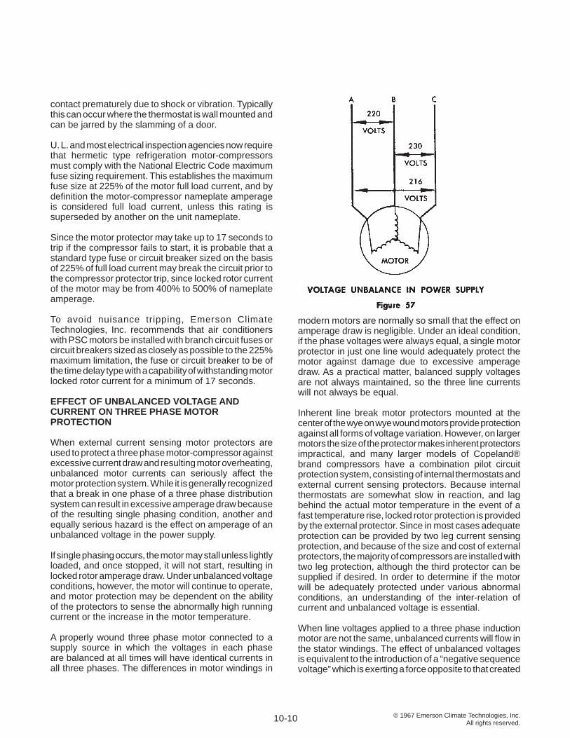
© 1967 Emerson Climate Technologies, Inc.All rights reserved.
contact prematurely due to shock or vibration. Typically this can occur where the thermostat is wall mounted and can be jarred by the slamming of a door.
U. L. and most electrical inspection agencies now require that hermetic type refrigeration motor-compressors must comply with the National Electric Code maximum fuse sizing requirement. This establishes the maximum fuse size at 225% of the motor full load current, and by defi nition the motor-compressor nameplate amperage is considered full load current, unless this rating is superseded by another on the unit nameplate.
Since the motor protector may take up to 17 seconds to trip if the compressor fails to start, it is probable that a standard type fuse or circuit breaker sized on the basis of 225% of full load current may break the circuit prior to the compressor protector trip, since locked rotor current of the motor may be from 400% to 500% of nameplate amperage.
To avoid nuisance tripping, Emerson Climate Technologies, Inc. recommends that air conditioners with PSC motors be installed with branch circuit fuses or circuit breakers sized as closely as possible to the 225% maximum limitation, the fuse or circuit breaker to be of the time delay type with a capability of withstanding motor locked rotor current for a minimum of 17 seconds.
EFFECT OF UNBALANCED VOLTAGE AND CURRENT ON THREE PHASE MOTOR PROTECTION
When external current sensing motor protectors are used to protect a three phase motor-compressor against excessive current draw and resulting motor overheating, unbalanced motor currents can seriously affect the motor protection system. While it is generally recognized that a break in one phase of a three phase distribution system can result in excessive amperage draw because of the resulting single phasing condition, another and equally serious hazard is the effect on amperage of an unbalanced voltage in the power supply.
If single phasing occurs, the motor may stall unless lightly loaded, and once stopped, it will not start, resulting in locked rotor amperage draw. Under unbalanced voltage conditions, however, the motor will continue to operate, and motor protection may be dependent on the ability of the protectors to sense the abnormally high running current or the increase in the motor temperature.
A properly wound three phase motor connected to a supply source in which the voltages in each phase are balanced at all times will have identical currents in all three phases. The differences in motor windings in
modern motors are normally so small that the effect on amperage draw is negligible. Under an ideal condition, if the phase voltages were always equal, a single motor protector in just one line would adequately protect the motor against damage due to excessive amperage draw. As a practical matter, balanced supply voltages are not always maintained, so the three line currents will not always be equal.
Inherent line break motor protectors mounted at the center of the wye on wye wound motors provide protection against all forms of voltage variation. However, on larger motors the size of the protector makes inherent protectors impractical, and many larger models of Copeland® brand compressors have a combination pilot circuit protection system, consisting of internal thermostats and external current sensing protectors. Because internal thermostats are somewhat slow in reaction, and lag behind the actual motor temperature in the event of a fast temperature rise, locked rotor protection is provided by the external protector. Since in most cases adequate protection can be provided by two leg current sensing protection, and because of the size and cost of external protectors, the majority of compressors are installed with two leg protection, although the third protector can be supplied if desired. In order to determine if the motor will be adequately protected under various abnormal conditions, an understanding of the inter-relation of current and unbalanced voltage is essential.
When line voltages applied to a three phase induction motor are not the same, unbalanced currents will fl ow in the stator windings. The effect of unbalanced voltages is equivalent to the introduction of a “negative sequence voltage” which is exerting a force opposite to that created
10-10
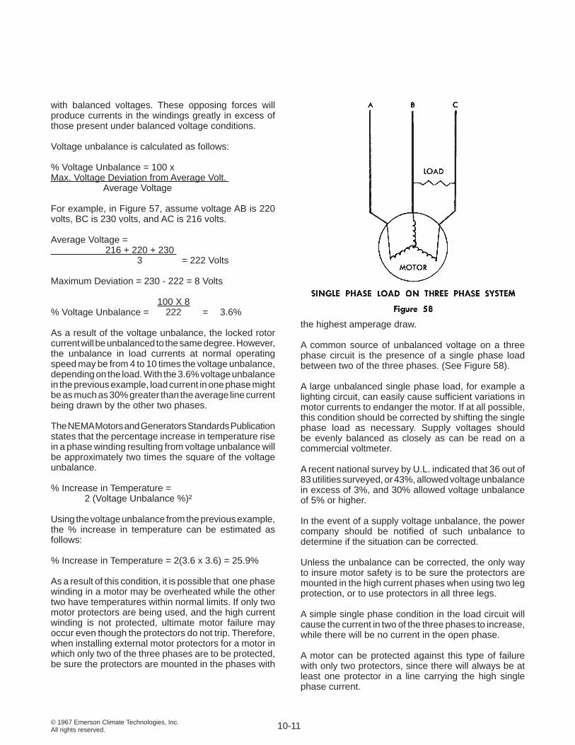
© 1967 Emerson Climate Technologies, Inc.All rights reserved.
with balanced voltages. These opposing forces will produce currents in the windings greatly in excess of those present under balanced voltage conditions.
Voltage unbalance is calculated as follows:
% Voltage Unbalance = 100 x Max. Voltage Deviation from Average Volt. Average Voltage
For example, in Figure 57, assume voltage AB is 220 volts, BC is 230 volts, and AC is 216 volts.
Average Voltage = 216 + 220 + 230 3 = 222 Volts
Maximum Deviation = 230 - 222 = 8 Volts
100 X 8 % Voltage Unbalance = 222 = 3.6%
As a result of the voltage unbalance, the locked rotor current will be unbalanced to the same degree. However, the unbalance in load currents at normal operating speed may be from 4 to 10 times the voltage unbalance, depending on the load. With the 3.6% voltage unbalance in the previous example, load current in one phase might be as much as 30% greater than the average line current being drawn by the other two phases.
The NEMA Motors and Generators Standards Publication states that the percentage increase in temperature rise in a phase winding resulting from voltage unbalance will be approximately two times the square of the voltage unbalance.
% Increase in Temperature = 2 (Voltage Unbalance %)²
Using the voltage unbalance from the previous example, the % increase in temperature can be estimated as follows:
% Increase in Temperature = 2(3.6 x 3.6) = 25.9%
As a result of this condition, it is possible that one phase winding in a motor may be overheated while the other two have temperatures within normal limits. If only two motor protectors are being used, and the high current winding is not protected, ultimate motor failure may occur even though the protectors do not trip. Therefore, when installing external motor protectors for a motor in which only two of the three phases are to be protected, be sure the protectors are mounted in the phases with
the highest amperage draw.
A common source of unbalanced voltage on a three phase circuit is the presence of a single phase load between two of the three phases. (See Figure 58).
A large unbalanced single phase load, for example a lighting circuit, can easily cause suffi cient variations in motor currents to endanger the motor. If at all possible, this condition should be corrected by shifting the single phase load as necessary. Supply voltages should be evenly balanced as closely as can be read on a commercial voltmeter.
A recent national survey by U.L. indicated that 36 out of 83 utilities surveyed, or 43%, allowed voltage unbalance in excess of 3%, and 30% allowed voltage unbalance of 5% or higher.
In the event of a supply voltage unbalance, the power company should be notifi ed of such unbalance to determine if the situation can be corrected.
Unless the unbalance can be corrected, the only way to insure motor safety is to be sure the protectors are mounted in the high current phases when using two leg protection, or to use protectors in all three legs.
A simple single phase condition in the load circuit will cause the current in two of the three phases to increase, while there will be no current in the open phase.
A motor can be protected against this type of failure with only two protectors, since there will always be at least one protector in a line carrying the high single phase current.
10-11
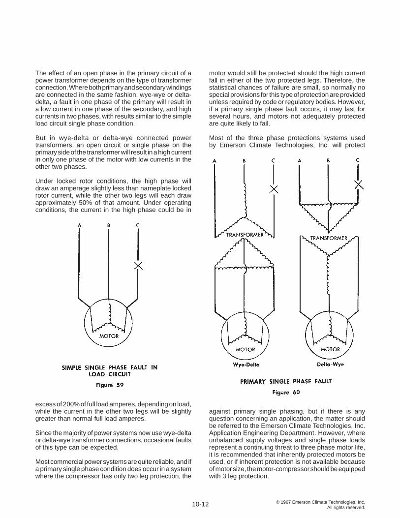
© 1967 Emerson Climate Technologies, Inc.All rights reserved.
The effect of an open phase in the primary circuit of a power transformer depends on the type of transformer connection. Where both primary and secondary windings are connected in the same fashion, wye-wye or delta-delta, a fault in one phase of the primary will result in a low current in one phase of the secondary, and high currents in two phases, with results similar to the simple load circuit single phase condition.
But in wye-delta or delta-wye connected power transformers, an open circuit or single phase on the primary side of the transformer will result in a high current in only one phase of the motor with low currents in the other two phases.
Under locked rotor conditions, the high phase will draw an amperage slightly less than nameplate locked rotor current, while the other two legs will each draw approximately 50% of that amount. Under operating conditions, the current in the high phase could be in
excess of 200% of full load amperes, depending on load, while the current in the other two legs will be slightly greater than normal full load amperes.
Since the majority of power systems now use wye-delta or delta-wye transformer connections, occasional faults of this type can be expected.
Most commercial power systems are quite reliable, and if a primary single phase condition does occur in a system where the compressor has only two leg protection, the
motor would still be protected should the high current fall in either of the two protected legs. Therefore, the statistical chances of failure are small, so normally no special provisions for this type of protection are provided unless required by code or regulatory bodies. However, if a primary single phase fault occurs, it may last for several hours, and motors not adequately protected are quite likely to fail.
Most of the three phase protections systems used by Emerson Climate Technologies, Inc. will protect
against primary single phasing, but if there is any question concerning an application, the matter should be referred to the Emerson Climate Technologies, Inc. Application Engineering Department. However, where unbalanced supply voltages and single phase loads represent a continuing threat to three phase motor life, it is recommended that inherently protected motors be used, or if inherent protection is not available because of motor size, the motor-compressor should be equipped with 3 leg protection.
10-12
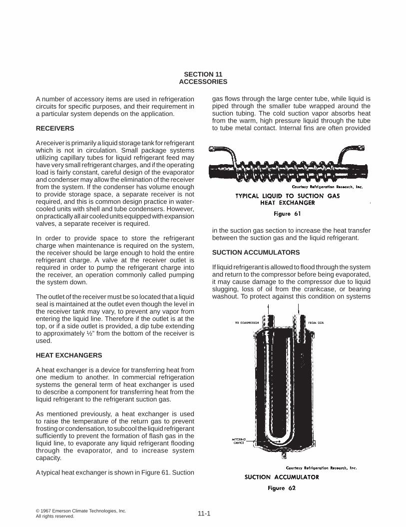
© 1967 Emerson Climate Technologies, Inc.All rights reserved.
SECTION 11ACCESSORIES
A number of accessory items are used in refrigeration circuits for specifi c purposes, and their requirement in a particular system depends on the application.
RECEIVERS
A receiver is primarily a liquid storage tank for refrigerant which is not in circulation. Small package systems utilizing capillary tubes for liquid refrigerant feed may have very small refrigerant charges, and if the operating load is fairly constant, careful design of the evaporator and condenser may allow the elimination of the receiver from the system. If the condenser has volume enough to provide storage space, a separate receiver is not required, and this is common design practice in water-cooled units with shell and tube condensers. However, on practically all air cooled units equipped with expansion valves, a separate receiver is required.
In order to provide space to store the refrigerant charge when maintenance is required on the system, the receiver should be large enough to hold the entire refrigerant charge. A valve at the receiver outlet is required in order to pump the refrigerant charge into the receiver, an operation commonly called pumping the system down.
The outlet of the receiver must be so located that a liquid seal is maintained at the outlet even though the level in the receiver tank may vary, to prevent any vapor from entering the liquid line. Therefore if the outlet is at the top, or if a side outlet is provided, a dip tube extending to approximately ½” from the bottom of the receiver is used.
HEAT EXCHANGERS
A heat exchanger is a device for transferring heat from one medium to another. In commercial refrigeration systems the general term of heat exchanger is used to describe a component for transferring heat from the liquid refrigerant to the refrigerant suction gas.
As mentioned previously, a heat exchanger is used to raise the temperature of the return gas to prevent frosting or condensation, to subcool the liquid refrigerant suffi ciently to prevent the formation of fl ash gas in the liquid line, to evaporate any liquid refrigerant fl ooding through the evaporator, and to increase system capacity.
A typical heat exchanger is shown in Figure 61. Suction
gas fl ows through the large center tube, while liquid is piped through the smaller tube wrapped around the suction tubing. The cold suction vapor absorbs heat from the warm, high pressure liquid through the tube to tube metal contact. Internal fi ns are often provided
in the suction gas section to increase the heat transfer between the suction gas and the liquid refrigerant.
SUCTION ACCUMULATORS
If liquid refrigerant is allowed to fl ood through the system and return to the compressor before being evaporated, it may cause damage to the compressor due to liquid slugging, loss of oil from the crankcase, or bearing washout. To protect against this condition on systems
11-1
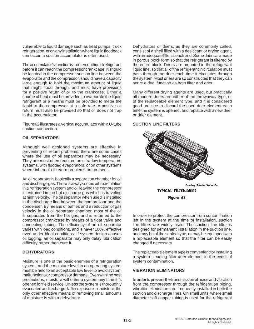
© 1967 Emerson Climate Technologies, Inc.All rights reserved.
vulnerable to liquid damage such as heat pumps, truck refrigeration, or on any installation where liquid fl oodback can occur, a suction accumulator is often used.
The accumulator’s function is to intercept liquid refrigerant before it can reach the compressor crankcase. It should be located in the compressor suction line between the evaporator and the compressor, should have a capacity large enough to hold the maximum amount of liquid that might fl ood through, and must have provisions for a positive return of oil to the crankcase. Either a source of heat must be provided to evaporate the liquid refrigerant or a means must be provided to meter the liquid to the compressor at a safe rate. A positive oil return must also be provided so that oil does not trap in the accumulator.
Figure 62 illustrates a vertical accumulator with a U-tube suction connection.
OIL SEPARATORS
Although well designed systems are effective in preventing oil return problems, there are some cases where the use of oil separators may be necessary. They are most often required on ultra-low temperature systems, with fl ooded evaporators, or on other systems where inherent oil return problems are present.
An oil separator is basically a separation chamber for oil and discharge gas. There is always some oil in circulation in a refrigeration system and oil leaving the compressor is entrained in the hot discharge gas which is traveling at high velocity. The oil separator when used is installed in the discharge line between the compressor and the condenser. By means of baffl es and a reduction of gas velocity in the oil separator chamber, most of the oil is separated from the hot gas, and is returned to the compressor crankcase by means of a fl oat valve and connecting tubing. The effi ciency of an oil separator varies with load conditions, and is never 100% effective even under ideal conditions. If system design causes oil logging, an oil separator may only delay lubrication diffi culty rather than cure it.
DEHYDRATORS
Moisture is one of the basic enemies of a refrigeration system, and the moisture level in an operating system must be held to an acceptable low level to avoid system malfunctions or compressor damage. Even with the best precautions, moisture will enter a system any time it is opened for fi eld service. Unless the system is thoroughly evacuated and recharged after exposure to moisture, the only other effective means of removing small amounts of moisture is with a dehydrator.
Dehydrators or driers, as they are commonly called, consist of a shell fi lled with a desiccant or drying agent, with an adequate fi lter at each end. Some driers are made in porous block form so that the refrigerant is fi ltered by the entire block. Driers are mounted in the refrigerant liquid line, so that all of the refrigerant in circulation must pass through the drier each time it circulates through the system. Most driers are so constructed that they can serve a dual function as both fi lter and drier.
Many different drying agents are used, but practically all modern driers are either of the throwaway type, or of the replaceable element type, and it is considered good practice to discard the used drier element each time the system is opened, and replace with a new drier or drier element.
SUCTION LINE FILTERS
In order to protect the compressor from contamination left in the system at the time of installation, suction line fi lters are widely used. The suction line fi lter is designed for permanent installation in the suction line, and may be of the sealed type, or may be equipped with a replaceable element so that the fi lter can be easily changed if necessary.
The replaceable element type is convenient for installing a system cleaning fi lter-drier element in the event of system contamination.
VIBRATION ELIMINATORS
In order to prevent the transmission of noise and vibration from the compressor through the refrigeration piping, vibration eliminators are frequently installed in both the suction and discharge lines. On small units, where small diameter soft copper tubing is used for the refrigerant
11-2
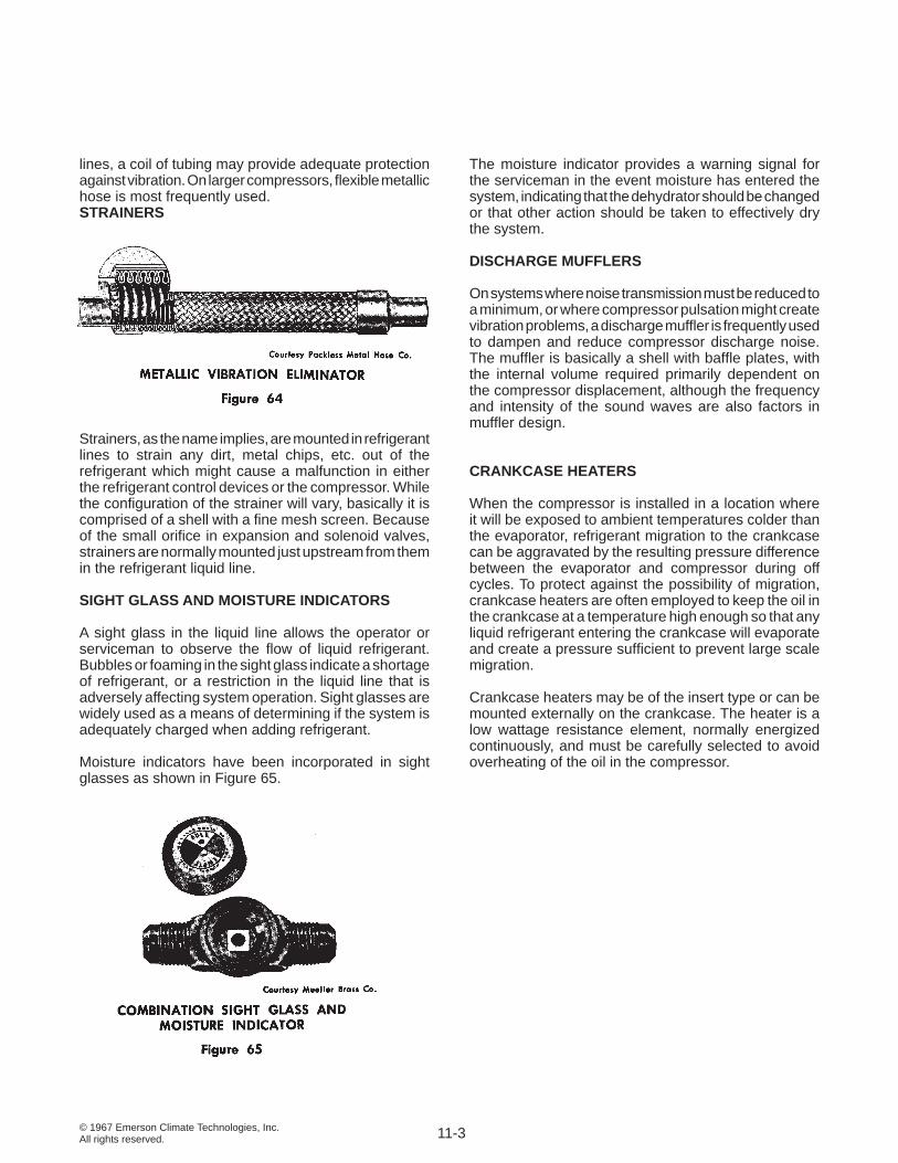
© 1967 Emerson Climate Technologies, Inc.All rights reserved.
lines, a coil of tubing may provide adequate protection against vibration. On larger compressors, fl exible metallic hose is most frequently used. STRAINERS
Strainers, as the name implies, are mounted in refrigerant lines to strain any dirt, metal chips, etc. out of the refrigerant which might cause a malfunction in either the refrigerant control devices or the compressor. While the confi guration of the strainer will vary, basically it is comprised of a shell with a fi ne mesh screen. Because of the small orifi ce in expansion and solenoid valves, strainers are normally mounted just upstream from them in the refrigerant liquid line.
SIGHT GLASS AND MOISTURE INDICATORS
A sight glass in the liquid line allows the operator or serviceman to observe the fl ow of liquid refrigerant. Bubbles or foaming in the sight glass indicate a shortage of refrigerant, or a restriction in the liquid line that is adversely affecting system operation. Sight glasses are widely used as a means of determining if the system is adequately charged when adding refrigerant.
Moisture indicators have been incorporated in sight glasses as shown in Figure 65.
The moisture indicator provides a warning signal for the serviceman in the event moisture has entered the system, indicating that the dehydrator should be changed or that other action should be taken to effectively dry the system.
DISCHARGE MUFFLERS
On systems where noise transmission must be reduced to a minimum, or where compressor pulsation might create vibration problems, a discharge muffl er is frequently used to dampen and reduce compressor discharge noise. The muffl er is basically a shell with baffl e plates, with the internal volume required primarily dependent on the compressor displacement, although the frequency and intensity of the sound waves are also factors in muffl er design.
CRANKCASE HEATERS
When the compressor is installed in a location where it will be exposed to ambient temperatures colder than the evaporator, refrigerant migration to the crankcase can be aggravated by the resulting pressure difference between the evaporator and compressor during off cycles. To protect against the possibility of migration, crankcase heaters are often employed to keep the oil in the crankcase at a temperature high enough so that any liquid refrigerant entering the crankcase will evaporate and create a pressure suffi cient to prevent large scale migration.
Crankcase heaters may be of the insert type or can be mounted externally on the crankcase. The heater is a low wattage resistance element, normally energized continuously, and must be carefully selected to avoid overheating of the oil in the compressor.
11-3
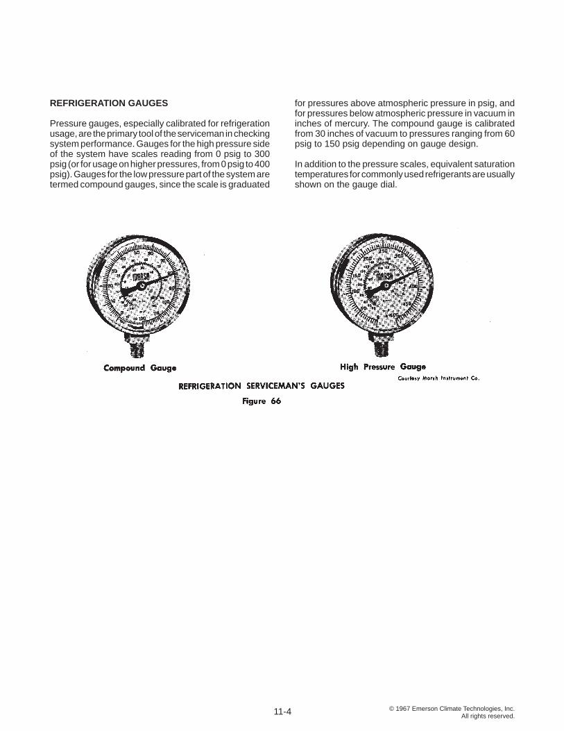
© 1967 Emerson Climate Technologies, Inc.All rights reserved.
REFRIGERATION GAUGES
Pressure gauges, especially calibrated for refrigeration usage, are the primary tool of the serviceman in checking system performance. Gauges for the high pressure side of the system have scales reading from 0 psig to 300 psig (or for usage on higher pressures, from 0 psig to 400 psig). Gauges for the low pressure part of the system are termed compound gauges, since the scale is graduated
for pressures above atmospheric pressure in psig, and for pressures below atmospheric pressure in vacuum in inches of mercury. The compound gauge is calibrated from 30 inches of vacuum to pressures ranging from 60 psig to 150 psig depending on gauge design.
In addition to the pressure scales, equivalent saturation temperatures for commonly used refrigerants are usually shown on the gauge dial.
11-4
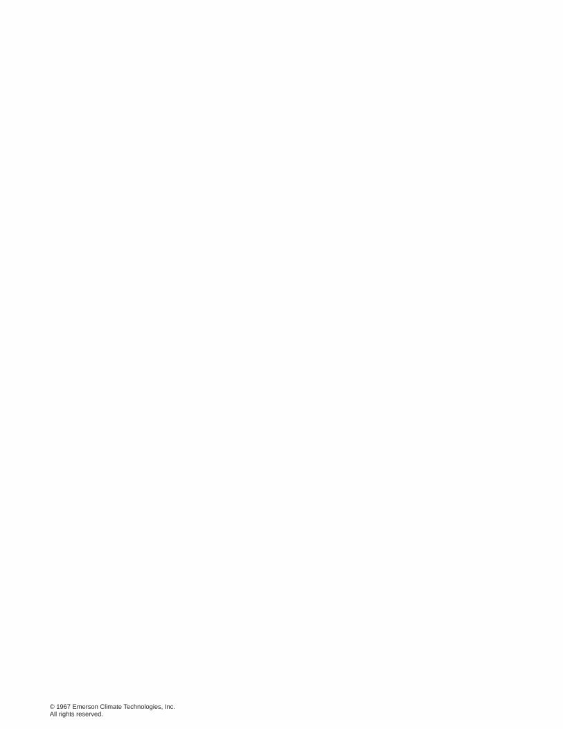
© 1967 Emerson Climate Technologies, Inc.All rights reserved.
© 1967 Emerson Climate Technologies, Inc.All rights reserved.
1675 W. Campbell Rd.Sidney, OH 45365
EmersonClimate.com
Form No. AE 102 R2 (10/06))Emerson, Copelametic, and Copeland are the trademarks of Emerson Electric Co. or one of its affi liated companies. ©1967 Emerson Climate Technologies, Inc. All rights reserved. Printed in the USA.