Embed Size (px)
Citation preview
! !
Regulatory Pre-compliance Testing for Wireless LAN Transmitter
Application Note What is covered:
! The workflow of WLAN module integration. ! The basics about the spectrum regulatory compliance/pre-compliance testing for
wireless devices, such as o FCC/IC rules in US/ Canada o ETSI rules in Europe
! How to use the Tektronix MDO4000B Series with SignalVu-PC software to perform some of the regulatory testing ahead of going to the official test labs for complete regulatory testing.
Spectrum Pre-compliance for Wireless LAN Regulatory Testing Application Note
2 www.tektronix.com/wifi
Table of Contents
The Workflow of WLAN Module Integration ................................................................. 3 If you want to add a Wi-Fi Module to your product, what's next?
What Is the Full Compliance Test for Wireless Devices ............................................. 5 Is the Standard Certification the Same As the Regulatory Compliance? What Are the Requirements for a WLAN Full Compliance? What Equipment Do You Need For a Full Compliance Test? What Is the Difference Between Intentional Radiators and Unintentional Radiators? What Is the Difference Between Conducted Emission Measurements, Conducted Measurements, and Radiated Emission Measurements? What Are Certification Labs?
The Easier Way for Regulatory WLAN Compliance is the Pre-compliance Test .................................................................................................... 11
What Are the Benefits of the Pre-compliance Test? Is the Pre-compliance the Same As the Full Compliance? Is It Possible To Get the Pre-Compliance Testing Done without Quasi Peak Detectors? What is the Probing Technology in the Pre-compliance Test?
How to Perform Mid-level Pre-compliance Test with the Tektronix MDO4000B and SignalVu-PC ..................................................................... 15
Three Basic Steps for Pre-compliance Test Step 1 In-band Domain Check:
! Transmit Power Measurement ! Power Spectrum Density Measurement ! Occupied Bandwidth Measurement
Step 2 Out-of-band Domain Check: ! Spectrum Emission Mask Measurement
Step 3 Spurious Domain Check: ! Spurious Emission Measurement All-in-one Tektronix WLAN Mid Level Pre-Compliance Wizard
Recommended Configuration for the MDO4000B and SignalVu-PC to Prepare for Spectrum Regulatory Pre-compliance Measurements ......................... 23 Diagnostics Are Not Limited to Preparing to Regulatory Compliance .................... 24
Spectrum Pre-compliance for Wireless LAN Regulatory Testing Application Note
3 www.tektronix.com/wifi
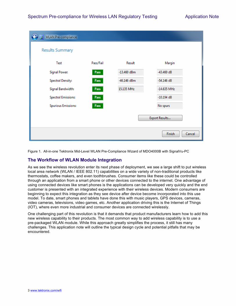
Figure 1. All-in-one Tektronix Mid-Level WLAN Pre-Compliance Wizard of MDO4000B with SignalVu-PC
The Workflow of WLAN Module Integration As we see the wireless revolution enter its next phase of deployment, we see a large shift to put wireless local area network (WLAN / IEEE 802.11) capabilities on a wide variety of non-traditional products like thermostats, coffee makers, and even toothbrushes. Consumer items like these could be controlled through an application from a smart phone or other devices connected to the internet. One advantage of using connected devices like smart phones is the applications can be developed very quickly and the end customer is presented with an integrated experience with their wireless devices. Modern consumers are beginning to expect this integration as they see device after device become incorporated into this use model. To date, smart phones and tablets have done this with music players, GPS devices, cameras, video cameras, televisions, video games, etc. Another application driving this is the Internet of Things (IOT), where even more industrial and consumer devices are connected wirelessly.
One challenging part of this revolution is that it demands that product manufacturers learn how to add this new wireless capability to their products. The most common way to add wireless capability is to use a pre-packaged WLAN module. While this approach greatly simplifies the process, it still has many challenges. This application note will outline the typical design cycle and potential pitfalls that may be encountered.
Spectrum Pre-compliance for Wireless LAN Regulatory Testing Application Note
4 www.tektronix.com/wifi
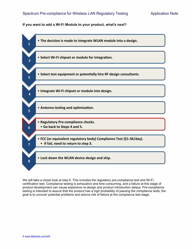
If you want to add a Wi-Fi Module to your product, what's next?
We will take a closer look at step 6. This includes the regulatory pre-compliance test and Wi-Fi certification test. Compliance testing is exhaustive and time consuming, and a failure at this stage of product development can cause expensive re-design and product introduction delays. Pre-compliance testing is intended to assure that the product has a high probability of passing the compliance tests; the goal is to uncover potential problems and reduce risk of failure at the compliance test stage.
!""!#$%"&%'()(*+"()",-&%".*"(+.%/0-.%"1234",*&56%"(+.*"-"&%)(/+7"
"8""!9%6%'."1(:;("'$(<)%."*0",*&56%"=*0"(+.%/0->*+7"
?""!9%6%'.".%)."%@5(<,%+."*0"<*.%+>-66A"$(0%"B;"&%)(/+"'*+)56.-+.)7"
"C""! D+.%/0-.%"1(:;("'$(<)%."*0",*&56%"(+.*"&%)(/+7"
E""!3+.%++-".%)>+/"-+&"*<>,(F->*+7"
G""!B%/56-.*0A"H0%:'*,<6(-+'%"'$%'I)7"""!J*"K-'I".*"9.%<)"C"-+&"E7"
L""!;MM"N*0"%@5(O-6%+."0%/56-.*0A"K*&AP"M*,<6(-+'%"#%)."NQ!:?RS&-AP7""! "D="=-(6T"+%%&".*"0%.50+".*").%<"?7"
U""!2*'I"&*V+".$%"1234"&%O('%"&%)(/+"-+&")$(<7"
Spectrum Pre-compliance for Wireless LAN Regulatory Testing Application Note
5 www.tektronix.com/wifi
What Is the Full Compliance Test for Wireless Devices From the first wireless transmissions, spectrum emission has been a concern for design engineers. Regulatory agencies have placed limits on the emission levels, and have defined measurement methods for compliance testing. Compliance testing requires methods, equipment and measurement sites in compliance with international standards. Compliance tests are commonly done as part of the design qualification prior to production of a device.
Is the Standard Certification the Same As the Regulatory Compliance? Wireless networks implemented in accordance with standards like IEEE 802.11 are subject to equipment certification and operation requirements established by regional and national regulatory administrations.
IEEE 802.11 Standard Certification
The standard specification, such as IEEE 802.11, is a set of media access control (MAC) and physical layer (PHY) specifications for implementing wireless local area network (WLAN). It establishes some minimum technical requirements for the wireless devices, based upon established regulations at the time the standard was issued. These regulations are subject to revision, or may be superseded.
Regulatory Compliance
Some other requirements are not specified by the standards, and are only subject to local geographic regulations. Operation in countries within defined regulatory domains may be subject to additional regulations. Implementers need to refer to the country regulatory sources for further information.
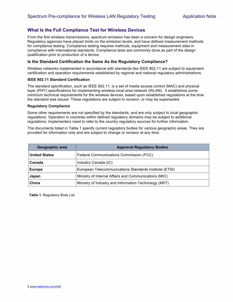
The documents listed in Table 1 specify current regulatory bodies for various geographic areas. They are provided for information only and are subject to change or revision at any time.
Geographic area Approval Regulatory Bodies
United States Federal Communications Commission (FCC)
Canada Industry Canada (IC)
Europe European Telecommunications Standards Institute (ETSI)
Japan Ministry of Internal Affairs and Communications (MIC)
China Ministry of Industry and Information Technology (MIIT)
Table 1. Regulatory Body List
Spectrum Pre-compliance for Wireless LAN Regulatory Testing Application Note
6 !
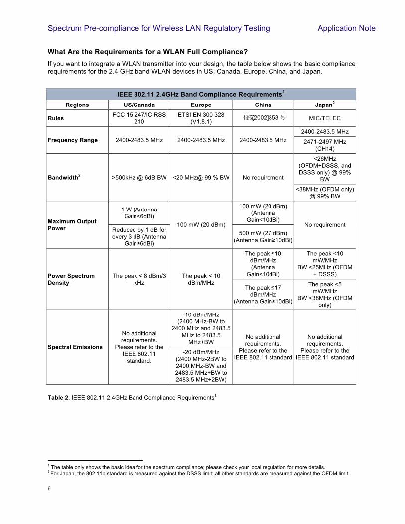
What Are the Requirements for a WLAN Full Compliance? If you want to integrate a WLAN transmitter into your design, the table below shows the basic compliance requirements for the 2.4 GHz band WLAN devices in US, Canada, Europe, China, and Japan.
Table 2. IEEE 802.11 2.4GHz Band Compliance Requirements#!
!
!!!!!!!!!!!!!!!!!!!!!!!!!!!!!!!!!!!!!!!!!!!!!!!!!!!!!!!!!!!!!1 The table only shows the basic idea for the spectrum compliance; please check your local regulation for more details. 2 For Japan, the 802.11b standard is measured against the DSSS limit; all other standards are measured against the OFDM limit.
IEEE 802.11 2.4GHz Band Compliance Requirements1 Regions US/Canada Europe China Japan2
Rules FCC 15.247/IC RSS 210
ETSI EN 300 328 (V1.8.1)
[2002]353 MIC/TELEC
Frequency Range 2400-2483.5 MHz 2400-2483.5 MHz 2400-2483.5 MHz 2400-2483.5 MHz
2471-2497 MHz (CH14)
Bandwidth2 >500kHz @ 6dB BW <20 MHz@ 99 % BW No requirement
<26MHz (OFDM+DSSS, and DSSS only) @ 99%
BW
<38MHz (OFDM only) @ 99% BW
Maximum Output Power
1 W (Antenna Gain<6dBi)
100 mW (20 dBm)
100 mW (20 dBm) (Antenna
Gain<10dBi) No requirement
Reduced by 1 dB for every 3 dB (Antenna
Gain!6dBi)
500 mW (27 dBm) (Antenna Gain!10dBi)
Power Spectrum Density
The peak < 8 dBm/3 kHz
The peak < 10 dBm/MHz
The peak "10 dBm/MHz (Antenna
Gain<10dBi)
The peak <10 mW/MHz
BW <25MHz (OFDM + DSSS)
The peak "17 dBm/MHz
(Antenna Gain!10dBi)
The peak <5 mW/MHz
BW <38MHz (OFDM only)
Spectral Emissions
No additional requirements.
Please refer to the IEEE 802.11
standard.
-10 dBm/MHz (2400 MHz-BW to
2400 MHz and 2483.5 MHz to 2483.5
MHz+BW No additional requirements.
Please refer to the IEEE 802.11 standard
No additional requirements.
Please refer to the IEEE 802.11 standard
-20 dBm/MHz (2400 MHz-2BW to 2400 MHz-BW and 2483.5 MHz+BW to 2483.5 MHz+2BW)
Spectrum Pre-compliance for Wireless LAN Regulatory Testing Application Note
7 !
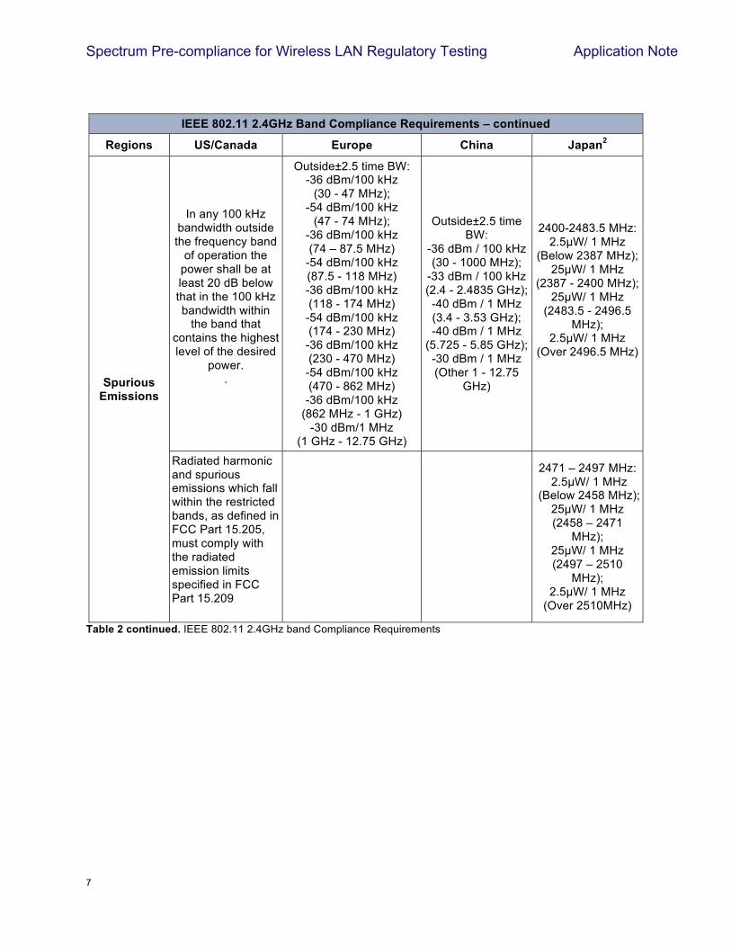
IEEE 802.11 2.4GHz Band Compliance Requirements – continued
Regions US/Canada Europe China Japan2
Spurious Emissions
In any 100 kHz bandwidth outside the frequency band
of operation the power shall be at least 20 dB below that in the 100 kHz bandwidth within
the band that contains the highest level of the desired
power. .
Outside±2.5 time BW: -36 dBm/100 kHz
(30 - 47 MHz); -54 dBm/100 kHz
(47 - 74 MHz); -36 dBm/100 kHz (74 – 87.5 MHz)
-54 dBm/100 kHz (87.5 - 118 MHz) -36 dBm/100 kHz (118 - 174 MHz) -54 dBm/100 kHz (174 - 230 MHz) -36 dBm/100 kHz (230 - 470 MHz) -54 dBm/100 kHz (470 - 862 MHz) -36 dBm/100 kHz
(862 MHz - 1 GHz) -30 dBm/1 MHz
(1 GHz - 12.75 GHz)
Outside±2.5 time BW:
-36 dBm / 100 kHz (30 - 1000 MHz);
-33 dBm / 100 kHz (2.4 - 2.4835 GHz); -40 dBm / 1 MHz (3.4 - 3.53 GHz); -40 dBm / 1 MHz
(5.725 - 5.85 GHz); -30 dBm / 1 MHz (Other 1 - 12.75
GHz)
2400-2483.5 MHz: 2.5#W/ 1 MHz
(Below 2387 MHz); 25#W/ 1 MHz
(2387 - 2400 MHz); 25#W/ 1 MHz
(2483.5 - 2496.5 MHz);
2.5#W/ 1 MHz (Over 2496.5 MHz)
Radiated harmonic and spurious emissions which fall within the restricted bands, as defined in FCC Part 15.205, must comply with the radiated emission limits specified in FCC Part 15.209
2471 – 2497 MHz: 2.5#W/ 1 MHz
(Below 2458 MHz); 25#W/ 1 MHz (2458 – 2471
MHz); 25#W/ 1 MHz (2497 – 2510
MHz); 2.5#W/ 1 MHz
(Over 2510MHz)
Table 2 continued. IEEE 802.11 2.4GHz band Compliance Requirements
Spectrum Pre-compliance for Wireless LAN Regulatory Testing Application Note
8 !
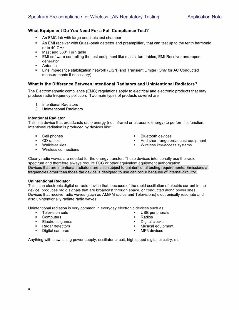
What Equipment Do You Need For a Full Compliance Test? ! An EMC lab with large anechoic test chamber ! An EMI receiver with Quasi-peak detector and preamplifier, that can test up to the tenth harmonic
or to 40 GHz ! Mast and 360° Turn table ! EMI software controlling the test equipment like masts, turn tables, EMI Receiver and report
generator ! Antenna ! Line impedance stabilization network (LISN) and Transient Limiter (Only for AC Conducted
measurements if necessary)
What Is the Difference Between Intentional Radiators and Unintentional Radiators? The Electromagnetic compliance (EMC) regulations apply to electrical and electronic products that may produce radio frequency pollution. Two main types of products covered are
1. Intentional Radiators 2. Unintentional Radiators
Intentional Radiator This is a device that broadcasts radio energy (not infrared or ultrasonic energy) to perform its function. Intentional radiation is produced by devices like:
! Cell phones ! CD radios ! Walkie-talkies ! Wireless connections
! Bluetooth devices ! And short range broadcast equipment ! Wireless key-access systems
Clearly radio waves are needed for the energy transfer. These devices intentionally use the radio spectrum and therefore always require FCC or other equivalent equipment authorization. Devices that are intentional radiators are also subject to unintentional testing requirements. Emissions at frequencies other than those the device is designed to use can occur because of internal circuitry. Unintentional Radiator This is an electronic digital or radio device that, because of the rapid oscillation of electric current in the device, produces radio signals that are broadcast through space, or conducted along power lines. Devices that receive radio waves (such as AM/FM radios and Televisions) electronically resonate and also unintentionally radiate radio waves.
Unintentional radiation is very common in everyday electronic devices such as:
! Television sets ! Computers ! Electronic games ! Radar detectors ! Digital cameras
! USB peripherals ! Radios ! Digital clocks ! Musical equipment ! MP3 devices
Anything with a switching power supply, oscillator circuit, high speed digital circuitry, etc.
Spectrum Pre-compliance for Wireless LAN Regulatory Testing Application Note
9 !
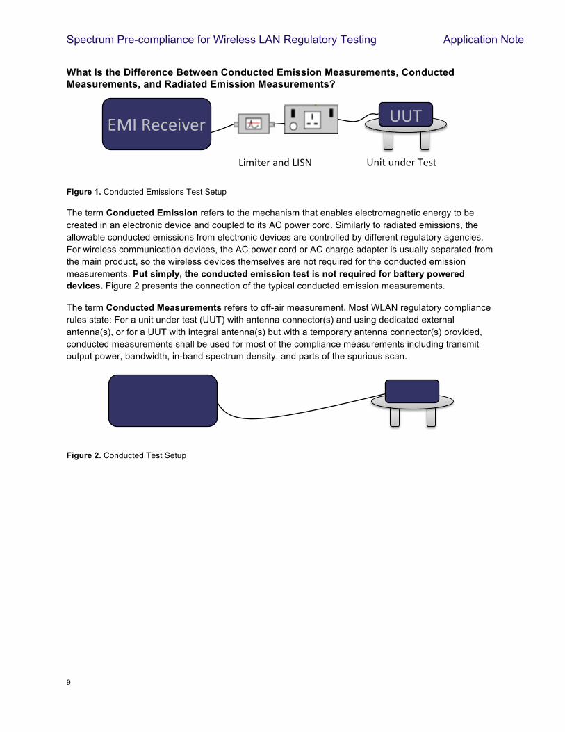
What Is the Difference Between Conducted Emission Measurements, Conducted Measurements, and Radiated Emission Measurements?
Figure 1. Conducted Emissions Test Setup
The term Conducted Emission refers to the mechanism that enables electromagnetic energy to be created in an electronic device and coupled to its AC power cord. Similarly to radiated emissions, the allowable conducted emissions from electronic devices are controlled by different regulatory agencies. For wireless communication devices, the AC power cord or AC charge adapter is usually separated from the main product, so the wireless devices themselves are not required for the conducted emission measurements. Put simply, the conducted emission test is not required for battery powered devices. Figure 2 presents the connection of the typical conducted emission measurements.
The term Conducted Measurements refers to off-air measurement. Most WLAN regulatory compliance rules state: For a unit under test (UUT) with antenna connector(s) and using dedicated external antenna(s), or for a UUT with integral antenna(s) but with a temporary antenna connector(s) provided, conducted measurements shall be used for most of the compliance measurements including transmit output power, bandwidth, in-band spectrum density, and parts of the spurious scan.
Figure 2. Conducted Test Setup
$%&%'()!*+,!$-./!
!!!!001!
0+%'!2+,()!1(3'!
45-!6(7(%8()!
Spectrum Pre-compliance for Wireless LAN Regulatory Testing Application Note
10 !
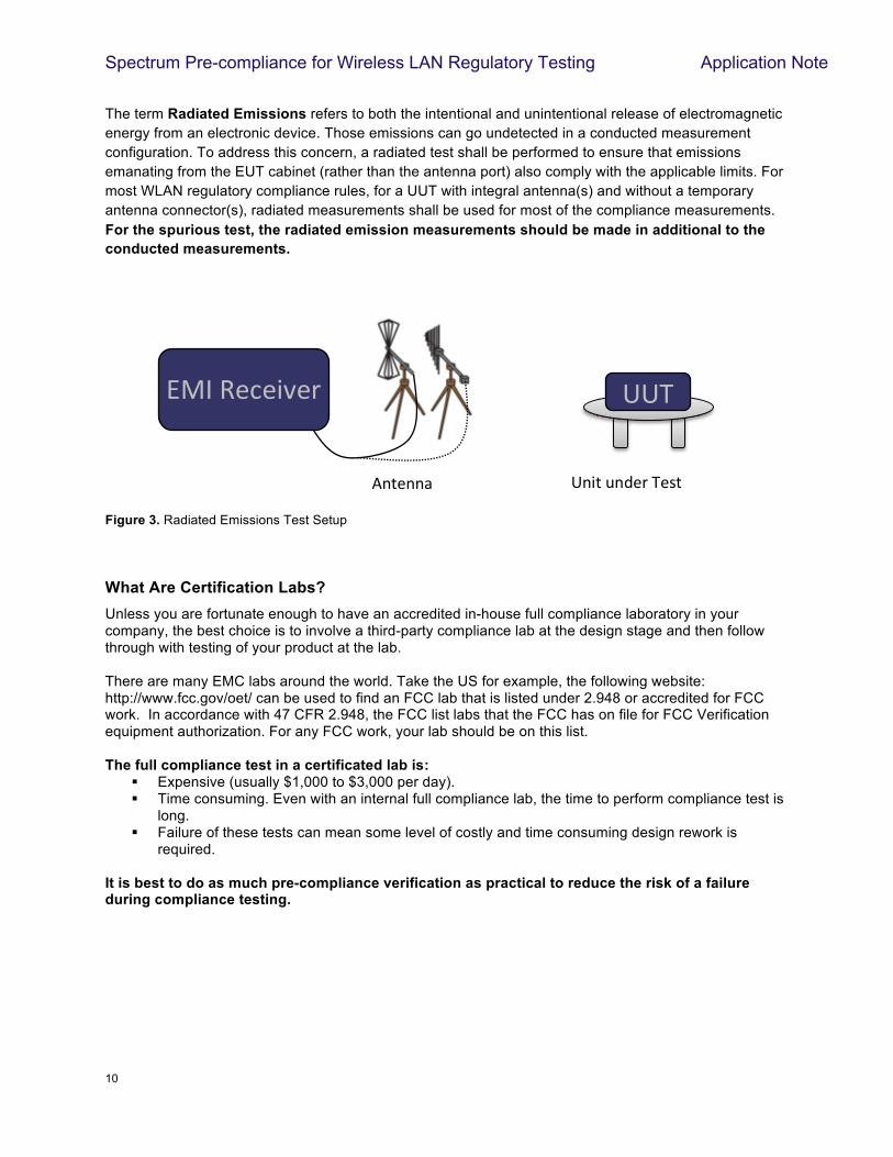
The term Radiated Emissions refers to both the intentional and unintentional release of electromagnetic energy from an electronic device. Those emissions can go undetected in a conducted measurement configuration. To address this concern, a radiated test shall be performed to ensure that emissions emanating from the EUT cabinet (rather than the antenna port) also comply with the applicable limits. For most WLAN regulatory compliance rules, for a UUT with integral antenna(s) and without a temporary antenna connector(s), radiated measurements shall be used for most of the compliance measurements. For the spurious test, the radiated emission measurements should be made in additional to the conducted measurements.
Figure 3. Radiated Emissions Test Setup
What Are Certification Labs? Unless you are fortunate enough to have an accredited in-house full compliance laboratory in your company, the best choice is to involve a third-party compliance lab at the design stage and then follow through with testing of your product at the lab. There are many EMC labs around the world. Take the US for example, the following website: http://www.fcc.gov/oet/ can be used to find an FCC lab that is listed under 2.948 or accredited for FCC work. In accordance with 47 CFR 2.948, the FCC list labs that the FCC has on file for FCC Verification equipment authorization. For any FCC work, your lab should be on this list. The full compliance test in a certificated lab is:
! Expensive (usually $1,000 to $3,000 per day). ! Time consuming. Even with an internal full compliance lab, the time to perform compliance test is
long. ! Failure of these tests can mean some level of costly and time consuming design rework is
required. It is best to do as much pre-compliance verification as practical to reduce the risk of a failure during compliance testing.
!
9+'(++*!!
001!
0+%'!2+,()!1(3'!
45-!6(7(%8()!
Spectrum Pre-compliance for Wireless LAN Regulatory Testing Application Note
11 !
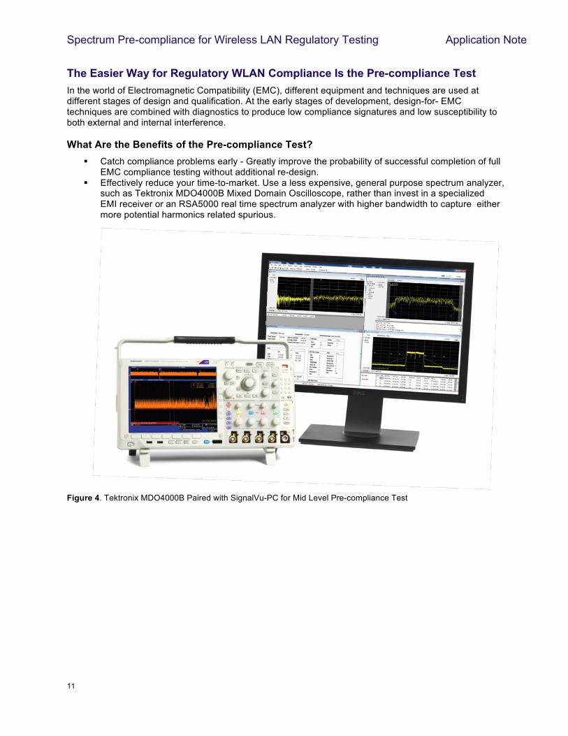
The Easier Way for Regulatory WLAN Compliance Is the Pre-compliance Test In the world of Electromagnetic Compatibility (EMC), different equipment and techniques are used at different stages of design and qualification. At the early stages of development, design-for- EMC techniques are combined with diagnostics to produce low compliance signatures and low susceptibility to both external and internal interference. What Are the Benefits of the Pre-compliance Test?
! Catch compliance problems early - Greatly improve the probability of successful completion of full EMC compliance testing without additional re-design.
! Effectively reduce your time-to-market. Use a less expensive, general purpose spectrum analyzer, such as Tektronix MDO4000B Mixed Domain Oscilloscope, rather than invest in a specialized EMI receiver or an RSA5000 real time spectrum analyzer with higher bandwidth to capture either more potential harmonics related spurious.
Figure 4. Tektronix MDO4000B Paired with SignalVu-PC for Mid Level Pre-compliance Test
Spectrum Pre-compliance for Wireless LAN Regulatory Testing Application Note
12 !
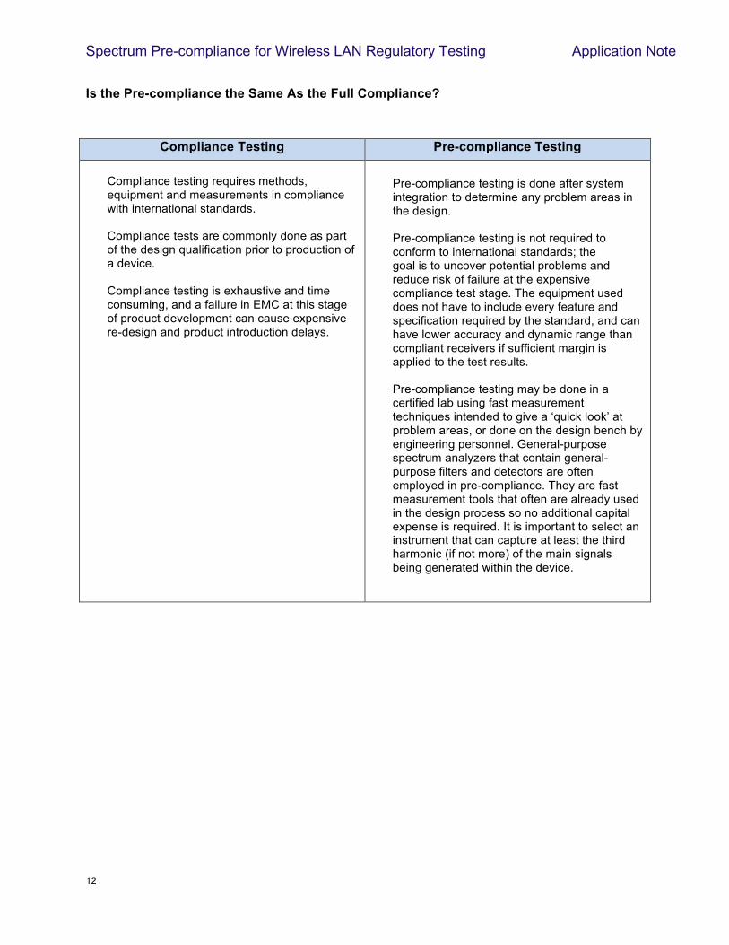
Is the Pre-compliance the Same As the Full Compliance?
!
Compliance Testing Pre-compliance Testing
Compliance testing requires methods, equipment and measurements in compliance with international standards.
Compliance tests are commonly done as part of the design qualification prior to production of a device.
Compliance testing is exhaustive and time consuming, and a failure in EMC at this stage of product development can cause expensive re-design and product introduction delays.
!
!Pre-compliance testing is done after system integration to determine any problem areas in the design.
Pre-compliance testing is not required to conform to international standards; the goal is to uncover potential problems and reduce risk of failure at the expensive compliance test stage. The equipment used does not have to include every feature and specification required by the standard, and can have lower accuracy and dynamic range than compliant receivers if sufficient margin is applied to the test results.
Pre-compliance testing may be done in a certified lab using fast measurement techniques intended to give a ‘quick look’ at problem areas, or done on the design bench by engineering personnel. General-purpose spectrum analyzers that contain general-purpose filters and detectors are often employed in pre-compliance. They are fast measurement tools that often are already used in the design process so no additional capital expense is required. It is important to select an instrument that can capture at least the third harmonic (if not more) of the main signals being generated within the device.
Spectrum Pre-compliance for Wireless LAN Regulatory Testing Application Note
13 !
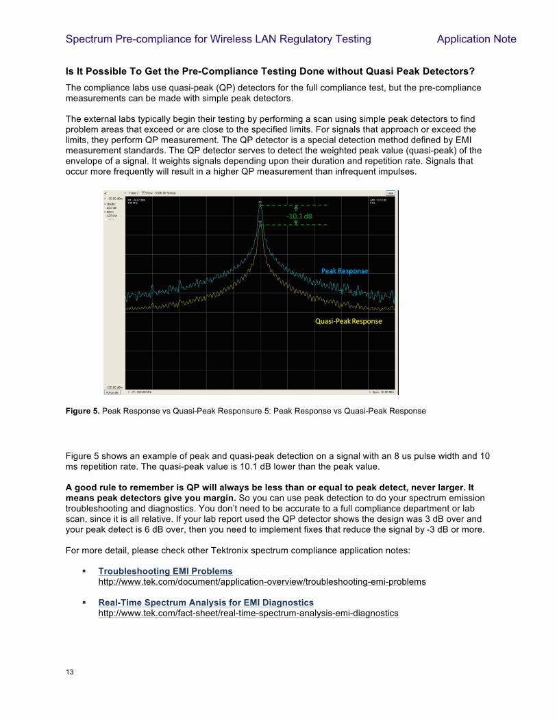
Is It Possible To Get the Pre-Compliance Testing Done without Quasi Peak Detectors? The compliance labs use quasi-peak (QP) detectors for the full compliance test, but the pre-compliance measurements can be made with simple peak detectors. The external labs typically begin their testing by performing a scan using simple peak detectors to find problem areas that exceed or are close to the specified limits. For signals that approach or exceed the limits, they perform QP measurement. The QP detector is a special detection method defined by EMI measurement standards. The QP detector serves to detect the weighted peak value (quasi-peak) of the envelope of a signal. It weights signals depending upon their duration and repetition rate. Signals that occur more frequently will result in a higher QP measurement than infrequent impulses.
Figure 5 shows an example of peak and quasi-peak detection on a signal with an 8 us pulse width and 10 ms repetition rate. The quasi-peak value is 10.1 dB lower than the peak value. A good rule to remember is QP will always be less than or equal to peak detect, never larger. It means peak detectors give you margin. So you can use peak detection to do your spectrum emission troubleshooting and diagnostics. You don’t need to be accurate to a full compliance department or lab scan, since it is all relative. If your lab report used the QP detector shows the design was 3 dB over and your peak detect is 6 dB over, then you need to implement fixes that reduce the signal by -3 dB or more. For more detail, please check other Tektronix spectrum compliance application notes:
! Troubleshooting EMI Problems http://www.tek.com/document/application-overview/troubleshooting-emi-problems
! Real-Time Spectrum Analysis for EMI Diagnostics http://www.tek.com/fact-sheet/real-time-spectrum-analysis-emi-diagnostics
Figure 5. Peak Response vs Quasi-Peak Responsure 5: Peak Response vs Quasi-Peak Response
Spectrum Pre-compliance for Wireless LAN Regulatory Testing Application Note
14 !
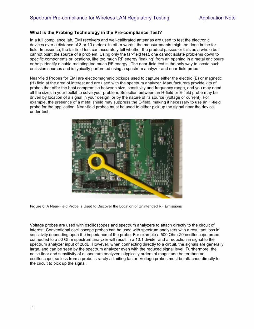
What is the Probing Technology in the Pre-compliance Test? In a full compliance lab, EMI receivers and well-calibrated antennas are used to test the electronic devices over a distance of 3 or 10 meters. In other words, the measurements might be done in the far field. In essence, the far field test can accurately tell whether the product passes or fails as a whole but cannot point the source of a problem. Using only the far-field test, one cannot isolate problems down to specific components or locations, like too much RF energy “leaking“ from an opening in a metal enclosure or help identify a cable radiating too much RF energy. The near-field test is the only way to locate such emission sources and is typically performed using a spectrum analyzer and near-field probe. Near-field Probes for EMI are electromagnetic pickups used to capture either the electric (E) or magnetic (H) field at the area of interest and are used with the spectrum analyzer. Manufacturers provide kits of probes that offer the best compromise between size, sensitivity and frequency range, and you may need all the sizes in your toolkit to solve your problem. Selection between an H-field or E-field probe may be driven by location of a signal in your design, or by the nature of its source (voltage or current). For example, the presence of a metal shield may suppress the E-field, making it necessary to use an H-field probe for the application. Near-field probes must be used to either pick up the signal near the device under test.
Figure 6. A Near-Field Probe Is Used to Discover the Location of Unintended RF Emissions
Voltage probes are used with oscilloscopes and spectrum analyzers to attach directly to the circuit of interest. Conventional oscilloscope probes can be used with spectrum analyzers with a resultant loss in sensitivity depending upon the impedance of the probe. For example a 500 Ohm Z0 oscilloscope probe connected to a 50 Ohm spectrum analyzer will result in a 10:1 divider and a reduction in signal to the spectrum analyzer input of 20dB. However, when connecting directly to a circuit, the signals are generally large, and can be seen by the spectrum analyzer even with the reduced signal level. Furthermore, the noise floor and sensitivity of a spectrum analyzer is typically orders of magnitude better than an oscilloscope, so loss from a probe is rarely a limiting factor. Voltage probes must be attached directly to the circuit to pick up the signal. !
!
!
Spectrum Pre-compliance for Wireless LAN Regulatory Testing Application Note
15 !
!
Which instrument to choose for pre-compliance?
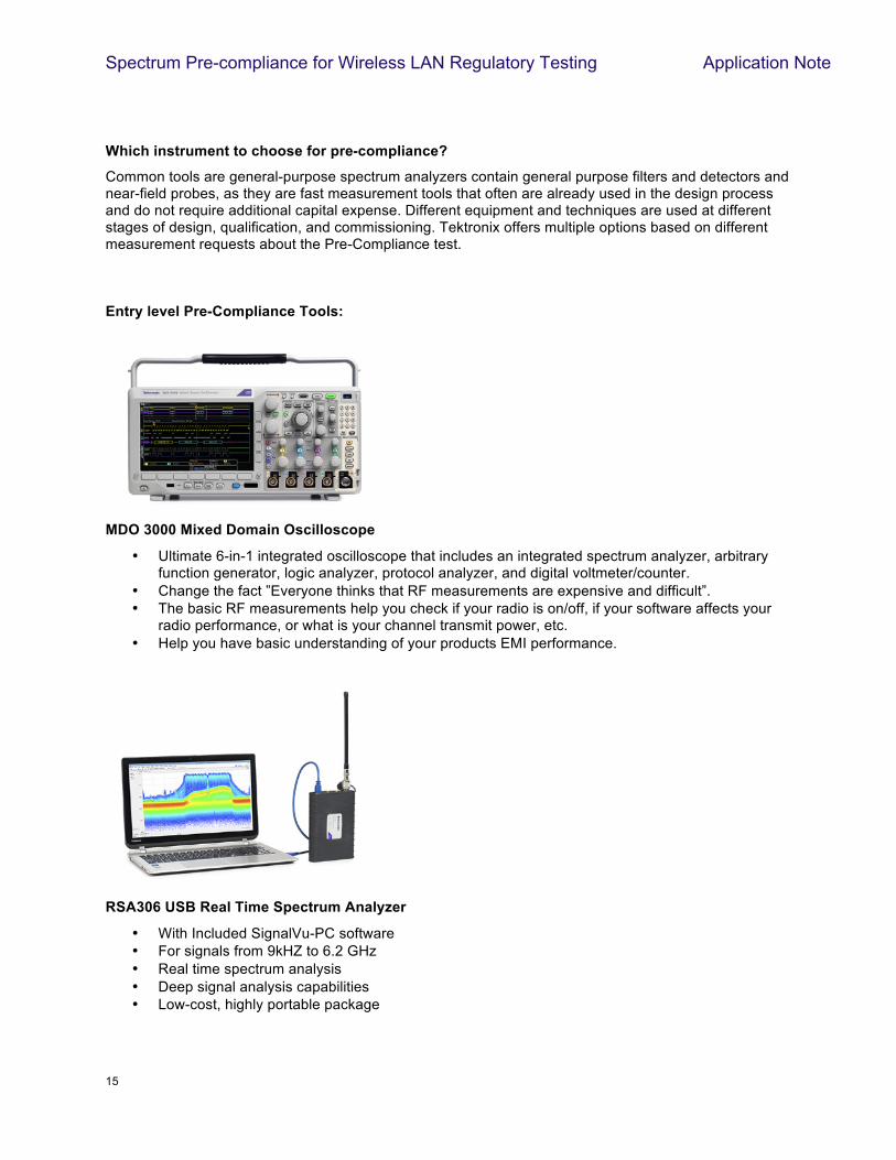
Common tools are general-purpose spectrum analyzers contain general purpose filters and detectors and near-field probes, as they are fast measurement tools that often are already used in the design process and do not require additional capital expense. Different equipment and techniques are used at different stages of design, qualification, and commissioning. Tektronix offers multiple options based on different measurement requests about the Pre-Compliance test. Entry level Pre-Compliance Tools:
MDO 3000 Mixed Domain Oscilloscope
• Ultimate 6-in-1 integrated oscilloscope that includes an integrated spectrum analyzer, arbitrary function generator, logic analyzer, protocol analyzer, and digital voltmeter/counter.
• Change the fact ”Everyone thinks that RF measurements are expensive and difficult”. • The basic RF measurements help you check if your radio is on/off, if your software affects your
radio performance, or what is your channel transmit power, etc. • Help you have basic understanding of your products EMI performance.
RSA306 USB Real Time Spectrum Analyzer
• With Included SignalVu-PC software • For signals from 9kHZ to 6.2 GHz • Real time spectrum analysis • Deep signal analysis capabilities • Low-cost, highly portable package
Spectrum Pre-compliance for Wireless LAN Regulatory Testing Application Note
16 !
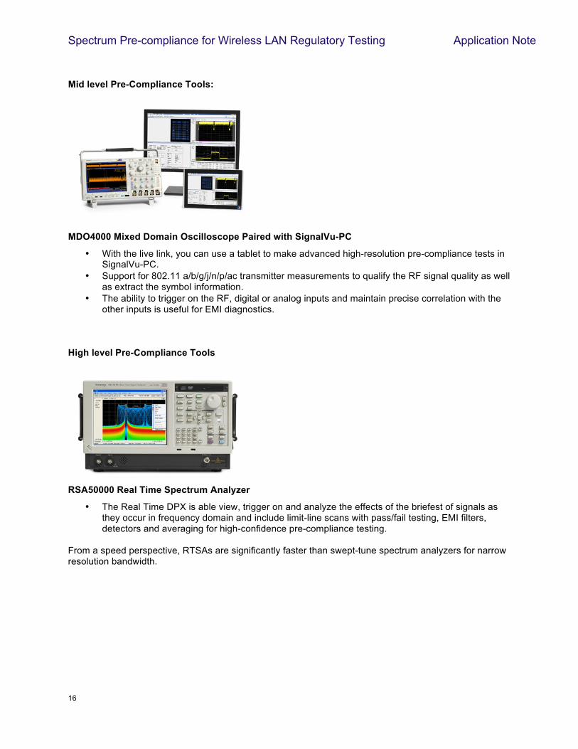
Mid level Pre-Compliance Tools:
MDO4000 Mixed Domain Oscilloscope Paired with SignalVu-PC
• With the live link, you can use a tablet to make advanced high-resolution pre-compliance tests in SignalVu-PC.
• Support for 802.11 a/b/g/j/n/p/ac transmitter measurements to qualify the RF signal quality as well as extract the symbol information.
• The ability to trigger on the RF, digital or analog inputs and maintain precise correlation with the other inputs is useful for EMI diagnostics.
High level Pre-Compliance Tools
RSA50000 Real Time Spectrum Analyzer
• The Real Time DPX is able view, trigger on and analyze the effects of the briefest of signals as they occur in frequency domain and include limit-line scans with pass/fail testing, EMI filters, detectors and averaging for high-confidence pre-compliance testing.
From a speed perspective, RTSAs are significantly faster than swept-tune spectrum analyzers for narrow resolution bandwidth.
Spectrum Pre-compliance for Wireless LAN Regulatory Testing Application Note
17 www.tektronix.com/wifi
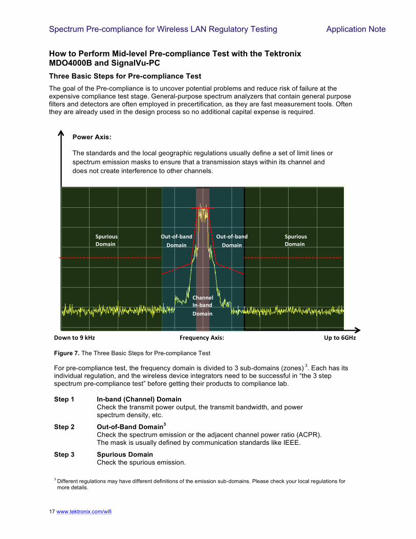
How to Perform Mid-level Pre-compliance Test with the Tektronix MDO4000B and SignalVu-PC Three Basic Steps for Pre-compliance Test The goal of the Pre-compliance is to uncover potential problems and reduce risk of failure at the expensive compliance test stage. General-purpose spectrum analyzers that contain general purpose filters and detectors are often employed in precertification, as they are fast measurement tools. Often they are already used in the design process so no additional capital expense is required.
!!
M$-++%6"D+:K-+&"W*,-(+"
9<50(*5)"W*,-(+"
9<50(*5)"W*,-(+"
X5.:*=:K-+&"W*,-(+"
""
X5.:*=:K-+&"W*,-(+"
"
Power Axis:
The standards and the local geographic regulations usually define a set of limit lines or spectrum emission masks to ensure that a transmission stays within its channel and does not create interference to other channels.
For pre-compliance test, the frequency domain is divided to 3 sub-domains (zones) 3. Each has its individual regulation, and the wireless device integrators need to be successful in “the 3 step spectrum pre-compliance test” before getting their products to compliance lab. Step 1 In-band (Channel) Domain Check the transmit power output, the transmit bandwidth, and power spectrum density, etc.
Step 2 Out-of-Band Domain3 Check the spectrum emission or the adjacent channel power ratio (ACPR). The mask is usually defined by communication standards like IEEE.
Step 3 Spurious Domain Check the spurious emission. 3 Different regulations may have different definitions of the emission sub-domains. Please check your local regulations for
more details.
!
W*V+".*"Y"IZF""""""""""""""""""""""""""""""""""""""""""""""""""""""";0%@5%+'A"3[()\"""""""""""""""""""""""""""""""""""""""""""""""""""""""""""""""""]<".*"GJZF"
Figure 7. The Three Basic Steps for Pre-compliance Test
18 !
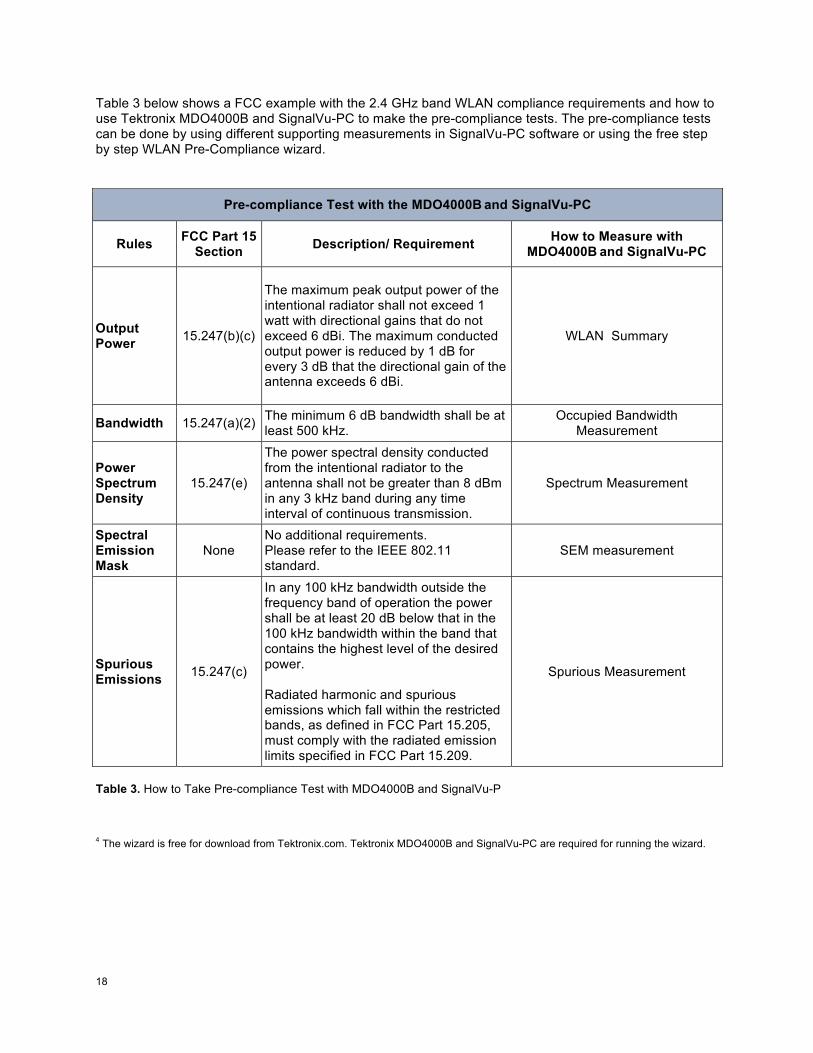
Table 3 below shows a FCC example with the 2.4 GHz band WLAN compliance requirements and how to use Tektronix MDO4000B and SignalVu-PC to make the pre-compliance tests. The pre-compliance tests can be done by using different supporting measurements in SignalVu-PC software or using the free step by step WLAN Pre-Compliance wizard.
Pre-compliance Test with the MDO4000B and SignalVu-PC
Rules FCC Part 15 Section Description/ Requirement How to Measure with
MDO4000B and SignalVu-PC
Output Power 15.247(b)(c)
The maximum peak output power of the intentional radiator shall not exceed 1 watt with directional gains that do not exceed 6 dBi. The maximum conducted output power is reduced by 1 dB for every 3 dB that the directional gain of the antenna exceeds 6 dBi.
WLAN Summary
Bandwidth 15.247(a)(2) The minimum 6 dB bandwidth shall be at least 500 kHz.
Occupied Bandwidth Measurement
Power Spectrum Density
15.247(e)
The power spectral density conducted from the intentional radiator to the antenna shall not be greater than 8 dBm in any 3 kHz band during any time interval of continuous transmission.
Spectrum Measurement
Spectral Emission Mask
None No additional requirements. Please refer to the IEEE 802.11 standard.
SEM measurement
Spurious Emissions 15.247(c)
In any 100 kHz bandwidth outside the frequency band of operation the power shall be at least 20 dB below that in the 100 kHz bandwidth within the band that contains the highest level of the desired power. Radiated harmonic and spurious emissions which fall within the restricted bands, as defined in FCC Part 15.205, must comply with the radiated emission limits specified in FCC Part 15.209.
Spurious Measurement
Table 3. How to Take Pre-compliance Test with MDO4000B and SignalVu-P
4 The wizard is free for download from Tektronix.com. Tektronix MDO4000B and SignalVu-PC are required for running the wizard.
19 !
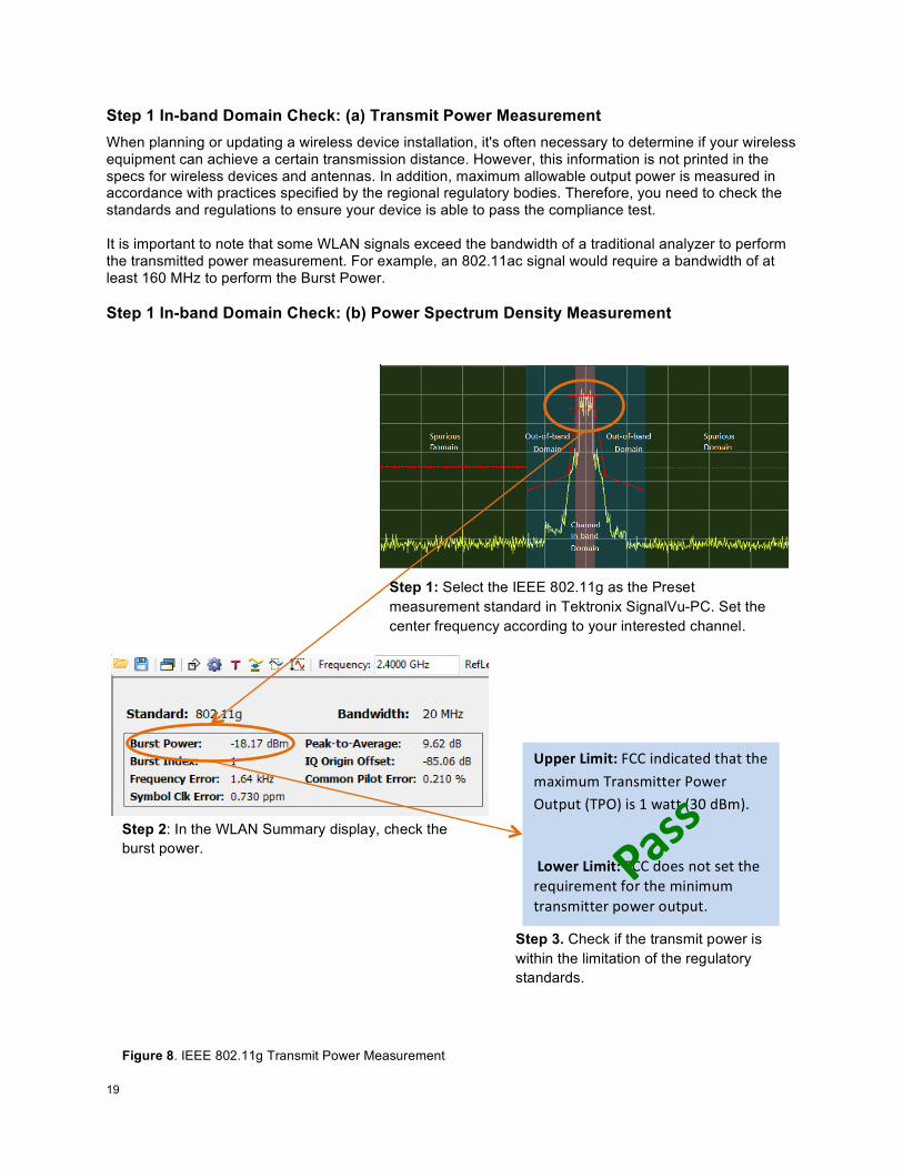
Step 1 In-band Domain Check: (a) Transmit Power Measurement When planning or updating a wireless device installation, it's often necessary to determine if your wireless equipment can achieve a certain transmission distance. However, this information is not printed in the specs for wireless devices and antennas. In addition, maximum allowable output power is measured in accordance with practices specified by the regional regulatory bodies. Therefore, you need to check the standards and regulations to ensure your device is able to pass the compliance test. It is important to note that some WLAN signals exceed the bandwidth of a traditional analyzer to perform the transmitted power measurement. For example, an 802.11ac signal would require a bandwidth of at least 160 MHz to perform the Burst Power. Step 1 In-band Domain Check: (b) Power Spectrum Density Measurement
]<<%0"2(,(.\!:;;!%+,%7*'(,!'<*'!'<(!&*=%&2&!1)*+3&%''()!>?@()!A2'B2'!C1>AD!%3!#!@*''!CEF!,G&DH!!!!2*V%0"2(,(.\!:;;!,?(3!+?'!3('!'<(!)(I2%)(&(+'!J?)!'<(!&%+%&2&!')*+3&%''()!B?@()!?2'B2'H!
!
Step 2: In the WLAN Summary display, check the burst power.
Step 3. Check if the transmit power is within the limitation of the regulatory standards.
H-))!
Step 1: Select the IEEE 802.11g as the Preset measurement standard in Tektronix SignalVu-PC. Set the center frequency according to your interested channel.
Figure 8. IEEE 802.11g Transmit Power Measurement
20 !
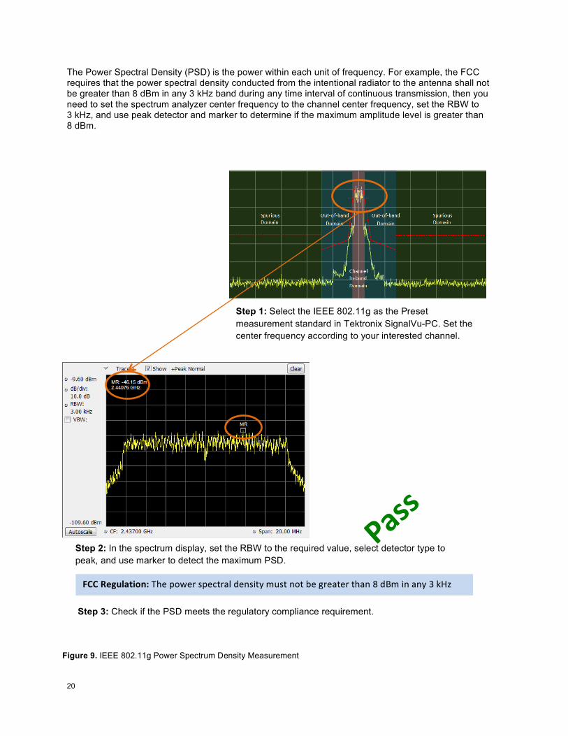
The Power Spectral Density (PSD) is the power within each unit of frequency. For example, the FCC requires that the power spectral density conducted from the intentional radiator to the antenna shall not be greater than 8 dBm in any 3 kHz band during any time interval of continuous transmission, then you need to set the spectrum analyzer center frequency to the channel center frequency, set the RBW to 3 kHz, and use peak detector and marker to determine if the maximum amplitude level is greater than 8 dBm.!
Step 2: In the spectrum display, set the RBW to the required value, select detector type to peak, and use marker to detect the maximum PSD.
Step 1: Select the IEEE 802.11g as the Preset measurement standard in Tektronix SignalVu-PC. Set the center frequency according to your interested channel.
!
!
;MM"B%/56-.(*+\!1<(!B?@()!3B(7')*K!,(+3%'L!&23'!+?'!M(!N)(*'()!'<*+!O!,G&!%+!*+L!E!PQR!!
Step 3: Check if the PSD meets the regulatory compliance requirement.
H-))!
Figure 9. IEEE 802.11g Power Spectrum Density Measurement
21 !
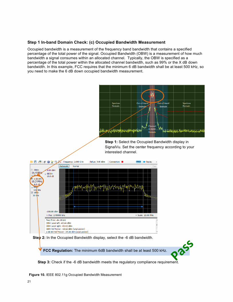
Step 1 In-band Domain Check: (c) Occupied Bandwidth Measurement Occupied bandwidth is a measurement of the frequency band bandwidth that contains a specified percentage of the total power of the signal. Occupied Bandwidth (OBW) is a measurement of how much bandwidth a signal consumes within an allocated channel. Typically, the OBW is specified as a percentage of the total power within the allocated channel bandwidth, such as 99% or the X dB down bandwidth. In this example, FCC requires that the minimum 6 dB bandwidth shall be at least 500 kHz, so you need to make the 6 dB down occupied bandwidth measurement.
FCC Regulation: The minimum 6dB bandwidth shall be at least 500 kHz.
!
Step 2: In the Occupied Bandwidth display, select the -6 dB bandwidth. !
Step 1: Select the Occupied Bandwidth display in SignalVu. Set the center frequency according to your interested channel.
Step 3: Check if the -6 dB bandwidth meets the regulatory compliance requirement. H-))!
Figure 10. IEEE 802.11g Occupied Bandwidth Measurement
22 !
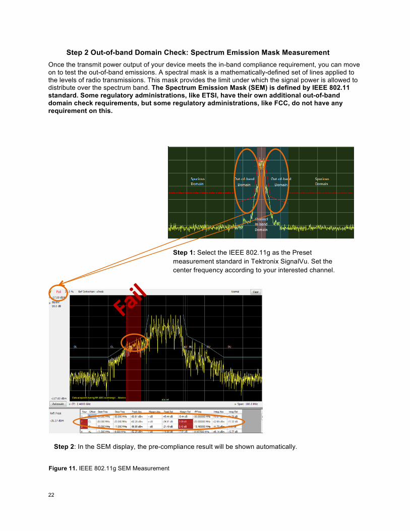
Step 2 Out-of-band Domain Check: Spectrum Emission Mask Measurement Once the transmit power output of your device meets the in-band compliance requirement, you can move on to test the out-of-band emissions. A spectral mask is a mathematically-defined set of lines applied to the levels of radio transmissions. This mask provides the limit under which the signal power is allowed to distribute over the spectrum band. The Spectrum Emission Mask (SEM) is defined by IEEE 802.11 standard. Some regulatory administrations, like ETSI, have their own additional out-of-band domain check requirements, but some regulatory administrations, like FCC, do not have any requirement on this.
Step 2: In the SEM display, the pre-compliance result will be shown automatically.
Step 1: Select the IEEE 802.11g as the Preset measurement standard in Tektronix SignalVu. Set the center frequency according to your interested channel.
;-(6!!
!
Figure 11. IEEE 802.11g SEM Measurement
23 !
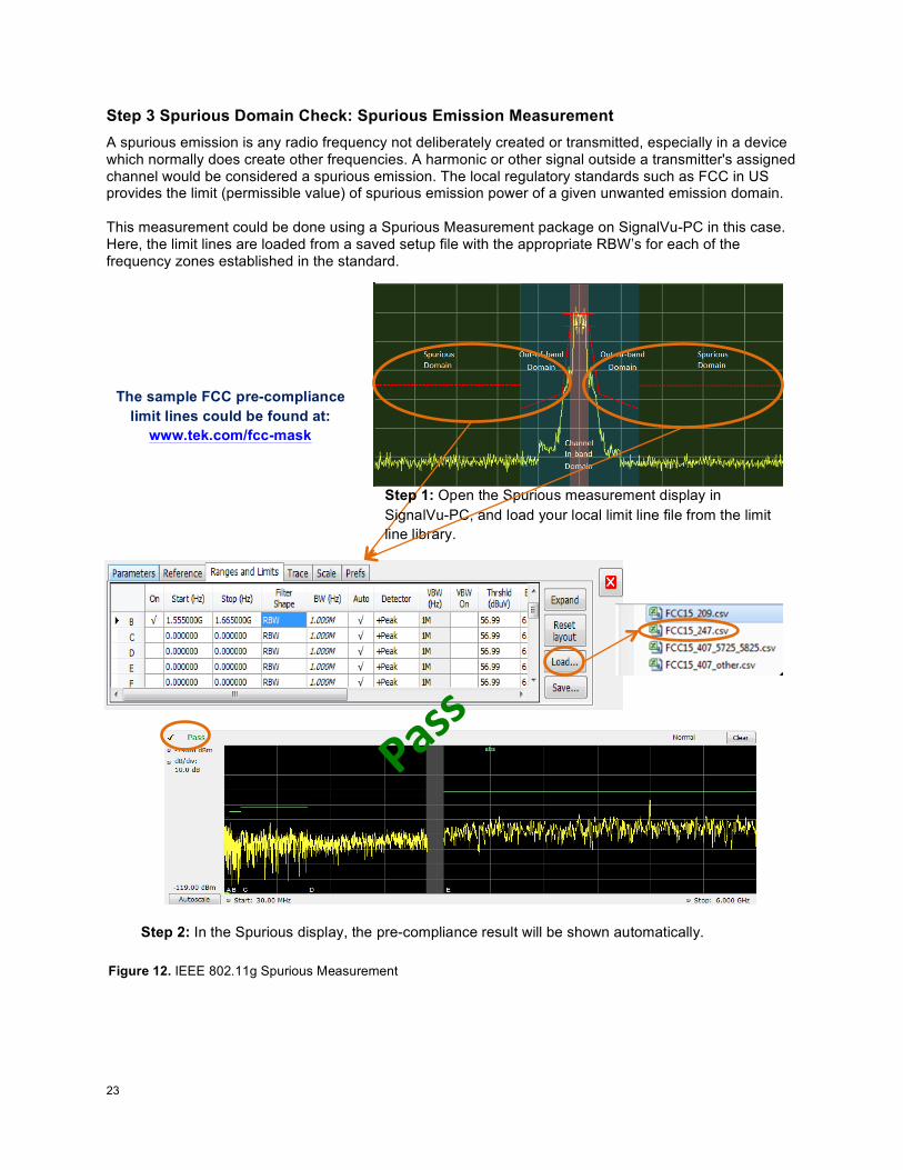
Step 3 Spurious Domain Check: Spurious Emission Measurement A spurious emission is any radio frequency not deliberately created or transmitted, especially in a device which normally does create other frequencies. A harmonic or other signal outside a transmitter's assigned channel would be considered a spurious emission. The local regulatory standards such as FCC in US provides the limit (permissible value) of spurious emission power of a given unwanted emission domain. This measurement could be done using a Spurious Measurement package on SignalVu-PC in this case. Here, the limit lines are loaded from a saved setup file with the appropriate RBW’s for each of the frequency zones established in the standard.
Step 2: In the Spurious display, the pre-compliance result will be shown automatically.
Step 1: Open the Spurious measurement display in SignalVu-PC, and load your local limit line file from the limit line library.
H-))!
!
!
The sample FCC pre-compliance limit lines could be found at:
www.tek.com/fcc-mask
Figure 12. IEEE 802.11g Spurious Measurement
24 !
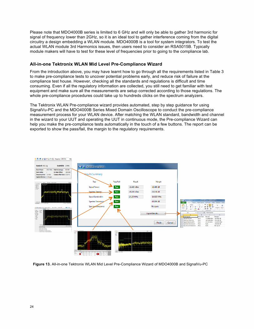
Please note that MDO4000B series is limited to 6 GHz and will only be able to gather 3rd harmonic for signal of frequency lower than 2GHz, so it is an ideal tool to gather interference coming from the digital circuitry a design embedding a WLAN module. MDO4000B is a tool for system integrators. To test the actual WLAN module 3rd Harmonics issues, then users need to consider an RSA5015B. Typically module makers will have to test for these level of frequencies prior to going to the compliance lab. All-in-one Tektronix WLAN Mid Level Pre-Compliance Wizard From the introduction above, you may have learnt how to go through all the requirements listed in Table 3 to make pre-compliance tests to uncover potential problems early, and reduce risk of failure at the compliance test house. However, checking all the standards and regulations is difficult and time consuming. Even if all the regulatory information are collected, you still need to get familiar with test equipment and make sure all the measurements are setup corrected according to those regulations. The whole pre-compliance procedures could take up to hundreds clicks on the spectrum analyzers. The Tektronix WLAN Pre-compliance wizard provides automated, step by step guidance for using SignalVu-PC and the MDO4000B Series Mixed Domain Oscilloscope to conduct the pre-compliance measurement process for your WLAN device. After matching the WLAN standard, bandwidth and channel in the wizard to your UUT and operating the UUT in continuous mode, the Pre-compliance Wizard can help you make the pre-compliance tests automatically in the touch of a few buttons. The report can be exported to show the pass/fail, the margin to the regulatory requirements.
Figure 13. All-in-one Tektronix WLAN Mid Level Pre-Compliance Wizard of MDO4000B and SignalVu-PC
25 !
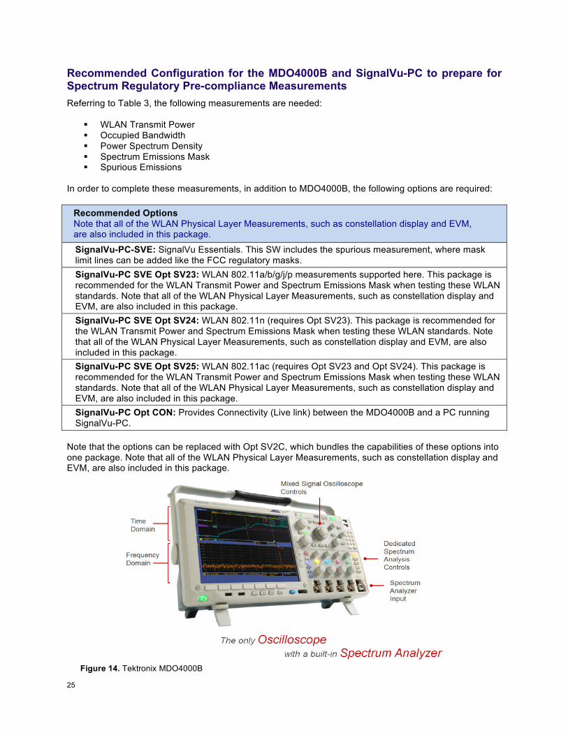
Recommended Configuration for the MDO4000B and SignalVu-PC to prepare for Spectrum Regulatory Pre-compliance Measurements Referring to Table 3, the following measurements are needed:
! WLAN Transmit Power ! Occupied Bandwidth ! Power Spectrum Density ! Spectrum Emissions Mask ! Spurious Emissions
In order to complete these measurements, in addition to MDO4000B, the following options are required:
Recommended Options Note that all of the WLAN Physical Layer Measurements, such as constellation display and EVM, are also included in this package.
SignalVu-PC-SVE: SignalVu Essentials. This SW includes the spurious measurement, where mask limit lines can be added like the FCC regulatory masks. SignalVu-PC SVE Opt SV23: WLAN 802.11a/b/g/j/p measurements supported here. This package is recommended for the WLAN Transmit Power and Spectrum Emissions Mask when testing these WLAN standards. Note that all of the WLAN Physical Layer Measurements, such as constellation display and EVM, are also included in this package. SignalVu-PC SVE Opt SV24: WLAN 802.11n (requires Opt SV23). This package is recommended for the WLAN Transmit Power and Spectrum Emissions Mask when testing these WLAN standards. Note that all of the WLAN Physical Layer Measurements, such as constellation display and EVM, are also included in this package. SignalVu-PC SVE Opt SV25: WLAN 802.11ac (requires Opt SV23 and Opt SV24). This package is recommended for the WLAN Transmit Power and Spectrum Emissions Mask when testing these WLAN standards. Note that all of the WLAN Physical Layer Measurements, such as constellation display and EVM, are also included in this package. SignalVu-PC Opt CON: Provides Connectivity (Live link) between the MDO4000B and a PC running SignalVu-PC.
Note that the options can be replaced with Opt SV2C, which bundles the capabilities of these options into one package. Note that all of the WLAN Physical Layer Measurements, such as constellation display and EVM, are also included in this package.
Figure 14. Tektronix MDO4000B !
26 !
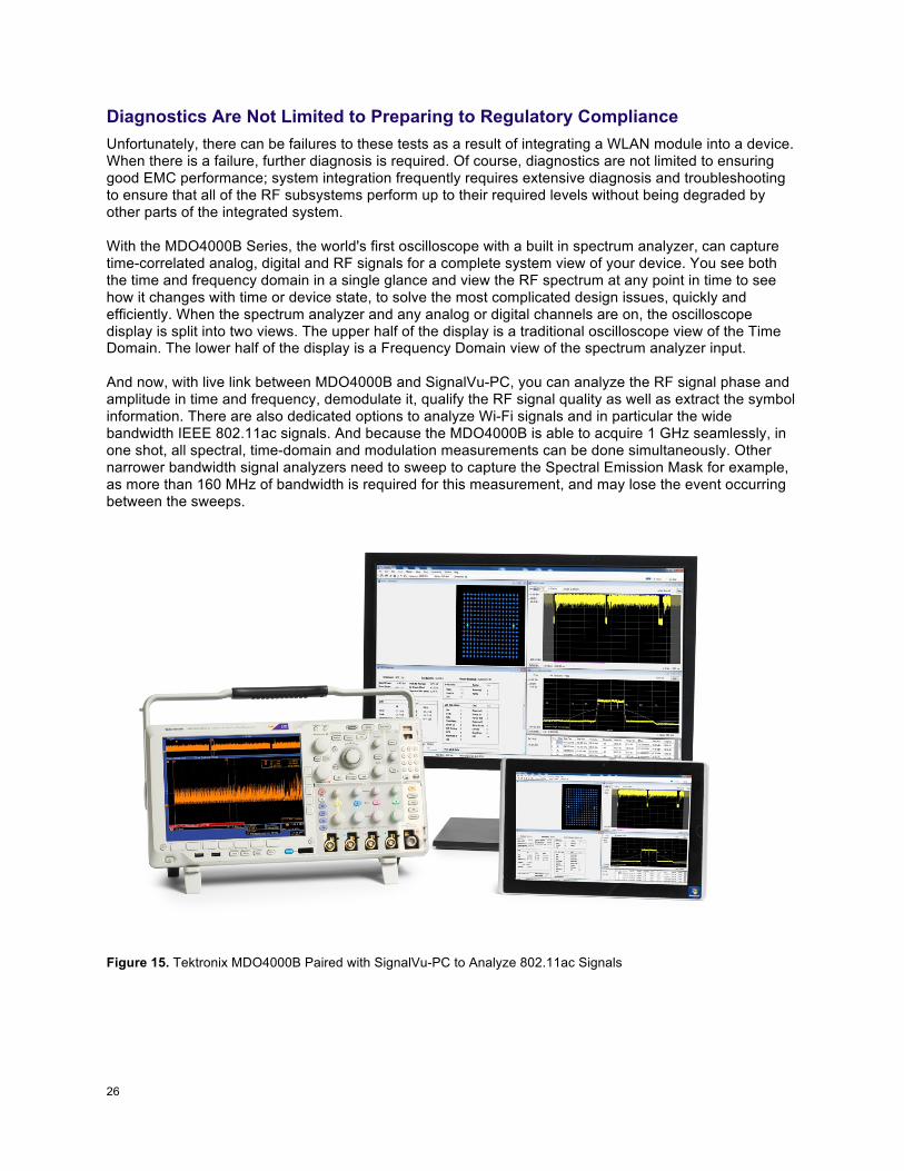
Diagnostics Are Not Limited to Preparing to Regulatory Compliance Unfortunately, there can be failures to these tests as a result of integrating a WLAN module into a device. When there is a failure, further diagnosis is required. Of course, diagnostics are not limited to ensuring good EMC performance; system integration frequently requires extensive diagnosis and troubleshooting to ensure that all of the RF subsystems perform up to their required levels without being degraded by other parts of the integrated system. With the MDO4000B Series, the world's first oscilloscope with a built in spectrum analyzer, can capture time-correlated analog, digital and RF signals for a complete system view of your device. You see both the time and frequency domain in a single glance and view the RF spectrum at any point in time to see how it changes with time or device state, to solve the most complicated design issues, quickly and efficiently. When the spectrum analyzer and any analog or digital channels are on, the oscilloscope display is split into two views. The upper half of the display is a traditional oscilloscope view of the Time Domain. The lower half of the display is a Frequency Domain view of the spectrum analyzer input. And now, with live link between MDO4000B and SignalVu-PC, you can analyze the RF signal phase and amplitude in time and frequency, demodulate it, qualify the RF signal quality as well as extract the symbol information. There are also dedicated options to analyze Wi-Fi signals and in particular the wide bandwidth IEEE 802.11ac signals. And because the MDO4000B is able to acquire 1 GHz seamlessly, in one shot, all spectral, time-domain and modulation measurements can be done simultaneously. Other narrower bandwidth signal analyzers need to sweep to capture the Spectral Emission Mask for example, as more than 160 MHz of bandwidth is required for this measurement, and may lose the event occurring between the sweeps.
Figure 15. Tektronix MDO4000B Paired with SignalVu-PC to Analyze 802.11ac Signals
27 !
ASEAN / Australia (65) 6356 3900 Austria* 00800 2255 4835
Balkans, Israel, South Africa and other ISE Countries +41 52 675 3777 Belgium* 00800 2255 4835 Brazil +55 (11) 3759 7627 Canada 1 (800) 833-9200
Central East Europe and the Baltics +41 52 675 3777 Central Europe & Greece +41 52 675 3777
Denmark +45 80 88 1401 Finland +41 52 675 3777
France* 00800 2255 4835 Germany* 00800 2255 4835
Hong Kong 400-820-5835 Ireland* 00800 2255 4835
India +91-80-30792600 Italy* 00800 2255 4835
Japan 0120-441-046 Luxembourg +41 52 675 3777
Macau 400-820-5835 Mongolia 400-820-5835
Mexico, Central/South America & Caribbean 52 (55) 56 04 50 90 Middle East, Asia and North Africa +41 52 675 3777
The Netherlands* 00800 2255 4835 Norway 800 16098
People’s Republic of China 400-820-5835 Poland +41 52 675 3777
Portugal 80 08 12370 Puerto Rico 1 (800) 833-9200
Republic of Korea +822-6917-5000 Russia +7 (495) 7484900 Singapore +65 6356-3900
South Africa +27 11 206 8360 Spain* 00800 2255 4835
Sweden* 00800 2255 4835 Switzerland* 00800 2255 4835
Taiwan 886-2-2656-6688 United Kingdom* 00800 2255 4835
USA 1 (800) 833-9200
* If the European phone number above is not accessible, please call +41 52 675 3777 Contact List Updated March 2013
For Further Information Tektronix maintains a comprehensive, constantly expanding
collection of application notes, technical briefs and other resources to help engineers working on the cutting edge of
technology. Please visit @@@H'(P')?+%=H7?&
Copyright © 2015, Tektronix. All rights reserved. Tektronix products are covered by U.S. and foreign patents, issued and pending. Information in this publication supersedes that in all previously published material. Specification and price change privileges
reserved. TEKTRONIX and TEK are registered trademarks of Tektronix, Inc. All other trade names referenced are the service marks, trademarks or registered trademarks of their respective companies. 01/2015 55W-30065-2
!!!