Embed Size (px)
Citation preview
“Andersen” and all other marks where denoted are trademarks of Andersen Corporation. ©2021 Andersen Corporation. All rights reserved. 9179729 BD -00 07/21/21
· Product Series - 100 Series· Product Type - Windows
Reinforced Joining InstructionsOne-Way Reinforced Joining or Two-Way Joining – Part 2
Read these instructions before starting procedure. For additional information visit www.andersenwindows.com. For questions call 1-888-888-7020.Para obtener una versión en español de esta guía, visite el sitio www.andersenwindows.com/joining guides
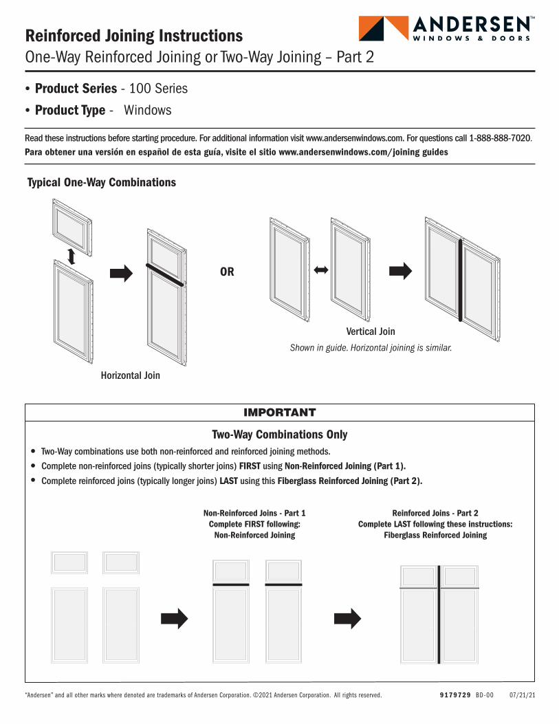
Vertical Join
Shown in guide. Horizontal joining is similar.
Horizontal Join
Typical One-Way Combinations
OR
Two-Way Combinations Only
IMPORTANT
Non-Reinforced Joins - Part 1Complete FIRST following:
Non-Reinforced Joining
Reinforced Joins - Part 2Complete LAST following these instructions:
Fiberglass Reinforced Joining
• Complete non-reinforced joins (typically shorter joins) FIRST using Non-Reinforced Joining (Part 1).
• Complete reinforced joins (typically longer joins) LAST using this Fiberglass Reinforced Joining (Part 2).
• Two-Way combinations use both non-reinforced and reinforced joining methods.
29179729
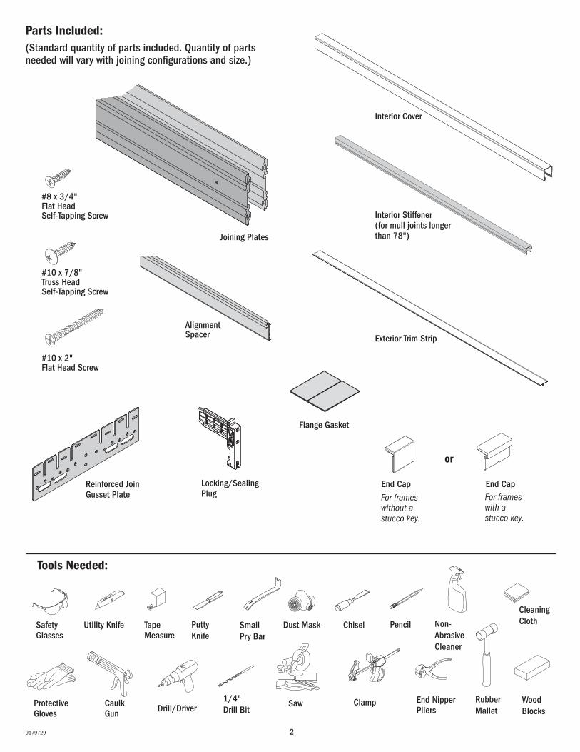
Flange Gasket
Reinforced Join Gusset Plate
Joining Plates
Exterior Trim Strip
Locking/Sealing Plug
Interior Stiffener (for mull joints longer than 78")
Interior Cover
Tools Needed:
Wood Blocks
Small Pry Bar
Parts Included:(Standard quantity of parts included. Quantity of parts needed will vary with joining configurations and size.)
Tape Measure
Dust Mask ChiselUtility Knife
Rubber Mallet
Saw Clamp
Safety Glasses
Caulk Gun
Protective Gloves
Putty Knife
End Nipper Pliers
Pencil
1/4" Drill Bit
Cleaning ClothNon-
Abrasive Cleaner
Drill/Driver
End Cap End CapFor frames with a stucco key.
For frames without a stucco key.
or
Alignment Spacer
#8 x 3/4" Flat Head Self-Tapping Screw
#10 x 7/8" Truss Head Self-Tapping Screw
#10 x 2" Flat Head Screw
39179729
Draft
Draft
1
Procedure and Product Information
IMPORTANT
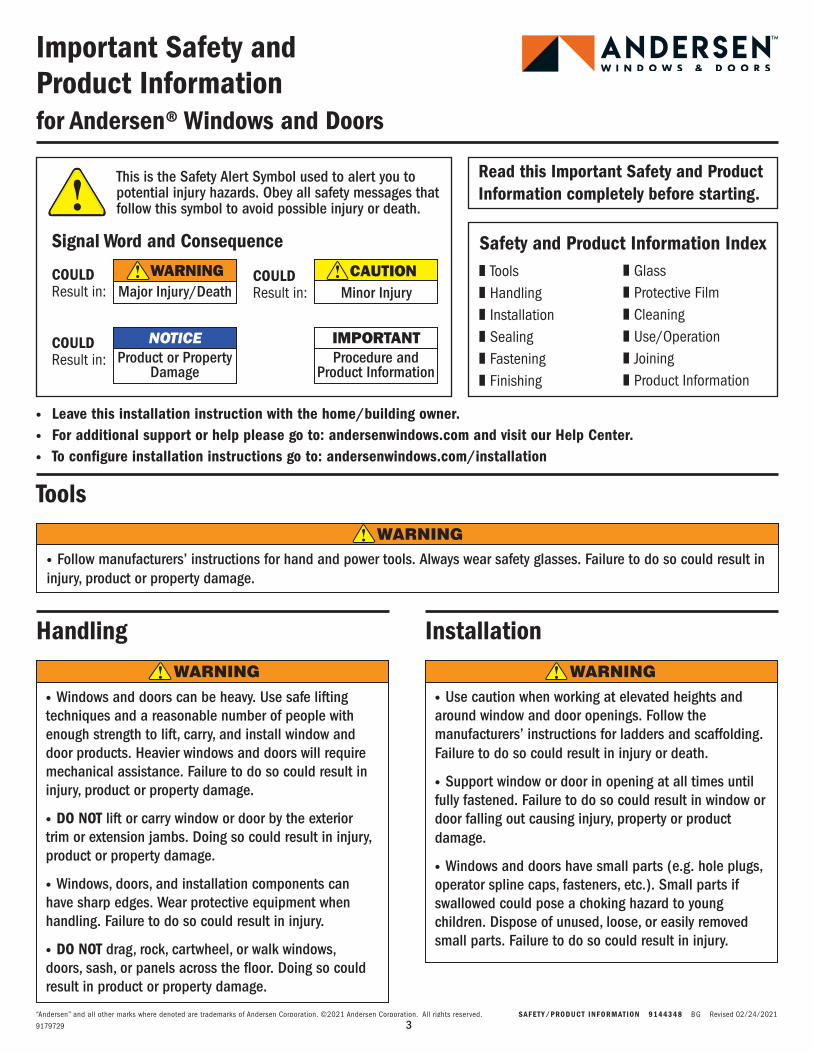
Important Safety and Product Informationfor Andersen® Windows and Doors
This is the Safety Alert Symbol used to alert you to potential injury hazards. Obey all safety messages that follow this symbol to avoid possible injury or death.
Signal Word and Consequence
Major Injury/DeathWARNINGCOULD
Result in: Minor InjuryCAUTIONCOULD
Result in:
Product or Property Damage
NOTICECOULDResult in:
· Leave this installation instruction with the home/building owner.· For additional support or help please go to: andersenwindows.com and visit our Help Center.· To configure installation instructions go to: andersenwindows.com/installation
Handling Installation
· Use caution when working at elevated heights and around window and door openings. Follow the manufacturers’ instructions for ladders and scaffolding. Failure to do so could result in injury or death.
· Support window or door in opening at all times until fully fastened. Failure to do so could result in window or door falling out causing injury, property or product damage.
· Windows and doors have small parts (e.g. hole plugs, operator spline caps, fasteners, etc.). Small parts if swallowed could pose a choking hazard to young children. Dispose of unused, loose, or easily removed small parts. Failure to do so could result in injury.
· Windows and doors can be heavy. Use safe lifting techniques and a reasonable number of people with enough strength to lift, carry, and install window and door products. Heavier windows and doors will require mechanical assistance. Failure to do so could result in injury, product or property damage.
· DO NOT lift or carry window or door by the exterior trim or extension jambs. Doing so could result in injury, product or property damage.
· Windows, doors, and installation components can have sharp edges. Wear protective equipment when handling. Failure to do so could result in injury.
· DO NOT drag, rock, cartwheel, or walk windows,doors, sash, or panels across the floor. Doing so couldresult in product or property damage.
Tools
· Follow manufacturers’ instructions for hand and power tools. Always wear safety glasses. Failure to do so could result in injury, product or property damage.
❚ Tools ❚ Handling ❚ Installation ❚ Sealing❚ Fastening❚ Finishing
Safety and Product Information Index❚ Glass❚ Protective Film ❚ Cleaning❚ Use/Operation❚ Joining ❚ Product Information
Read this Important Safety and Product Information completely before starting.
WARNING
WARNING WARNING
“Andersen” and all other marks where denoted are trademarks of Andersen Corporation. ©2021 Andersen Corporation. All rights reserved. SAFETY/PRODUCT INFORMATION 9144348 BG Revised 02/24/2021
49179729
Draft
Draft
2
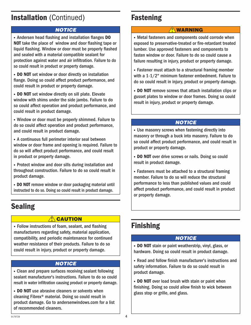
NOTICE· Andersen head flashing and installation flanges DO NOT take the place of window and door flashing tape or liquid flashing. Window or door must be properly flashed and sealed with a material compatible sealant for protection against water and air infiltration. Failure to do so could result in product or property damage.
· DO NOT set window or door directly on installation flange. Doing so could affect product performance, and could result in product or property damage.
· DO NOT set window directly on sill plate. Elevate window with shims under the side jambs. Failure to do so could affect operation and product performance, and could result in product damage.
· Window or door must be properly shimmed. Failure to do so could affect operation and product performance, and could result in product damage.
· A continuous full perimeter interior seal between window or door frame and opening is required. Failure to do so will affect product performance, and could result in product or property damage.
· Protect window and door sills during installation and throughout construction. Failure to do so could result in product damage.
· DO NOT remove window or door packaging material until instructed to do so. Doing so could result in product damage.
Installation (Continued)
NOTICE· Use masonry screws when fastening directly into masonry or through a buck into masonry. Failure to do so could affect product performance, and could result in product or property damage.
· DO NOT over drive screws or nails. Doing so could result in product damage.
· Fasteners must be attached to a structural framing member. Failure to do so will reduce the structural performance to less than published values and could affect product performance, and could result in product or property damage.
Fastening
· Metal fasteners and components could corrode when exposed to preservative-treated or fire-retardant treated lumber. Use approved fasteners and components to fasten window or door. Failure to do so could cause a failure resulting in injury, product or property damage.
· Fastener must attach to a structural framing member with a 1-1/2" minimum fastener embedment. Failure to do so could result in injury, product or property damage.
· DO NOT remove screws that attach installation clips or gusset plates to window or door frames. Doing so could result in injury, product or property damage.
Sealing
NOTICE
CAUTION· Follow instructions of foam, sealant, and flashing manufacturers regarding safety, material application, compatibility, and periodic maintenance for continued weather resistance of their products. Failure to do so could result in injury, product or property damage.
FinishingNOTICE
· DO NOT stain or paint weatherstrip, vinyl, glass, or hardware. Doing so could result in product damage.
· Read and follow finish manufacturer's instructions and safety information. Failure to do so could result in product damage.
· DO NOT over load brush with stain or paint when finishing. Doing so could allow finish to wick between glass stop or grille, and glass.
WARNING
· Clean and prepare surfaces receiving sealant following sealant manufacturer's instructions. Failure to do so could result in water infiltration causing product or property damage.
· DO NOT use abrasive cleaners or solvents when cleaning Fibrex® material. Doing so could result in product damage. Go to andersenwindows.com for a list of recommended cleaners.
59179729
Draft
Draft
3
NOTICE
Glass
· Unless specifically ordered, Andersen windows are not equipped with safety glass, and if broken, could fragment causing injury. Many laws and building codes require safety glass in locations adjacent to or near doors. Andersen windows are available with safety glass that could reduce the likelihood of injury when broken. Information on safety glass is available from your local Andersen dealer.
· Tempered or laminated safety glass is not standard for windows and must be special ordered. Check local building codes for required locations. Failure to do so could result in injury, product or property damage.
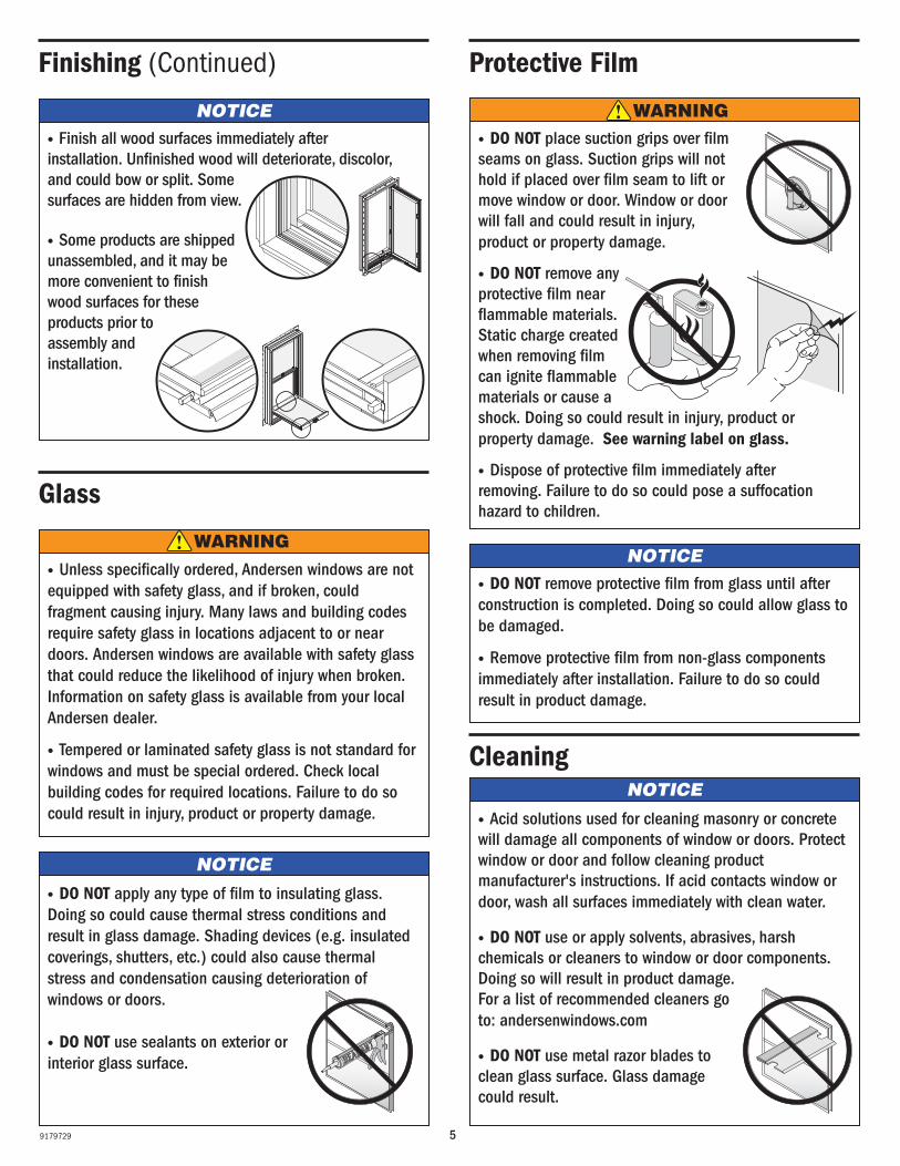
· DO NOT place suction grips over filmseams on glass. Suction grips will not hold if placed over film seam to lift or move window or door. Window or door will fall and could result in injury, product or property damage.
· DO NOT remove any protective film near flammable materials. Static charge created when removing film can ignite flammable materials or cause a shock. Doing so could result in injury, product or property damage. See warning label on glass.
· Dispose of protective film immediately afterremoving. Failure to do so could pose a suffocationhazard to children.
NOTICE· DO NOT remove protective film from glass until afterconstruction is completed. Doing so could allow glass tobe damaged.
· Remove protective film from non-glass componentsimmediately after installation. Failure to do so couldresult in product damage.
NOTICE
Cleaning
Protective FilmFinishing (Continued)
· Finish all wood surfaces immediately afterinstallation. Unfinished wood will deteriorate, discolor,and could bow or split. Somesurfaces are hidden from view.
· Some products are shippedunassembled, and it may bemore convenient to finishwood surfaces for theseproducts prior to assembly and installation.
WARNING
WARNING
· Acid solutions used for cleaning masonry or concrete will damage all components of window or doors. Protect window or door and follow cleaning product manufacturer's instructions. If acid contacts window or door, wash all surfaces immediately with clean water.
· DO NOT use or apply solvents, abrasives, harsh chemicals or cleaners to window or door components. Doing so will result in product damage. For a list of recommended cleaners go to: andersenwindows.com
· DO NOT use metal razor blades toclean glass surface. Glass damagecould result.
· DO NOT apply any type of film to insulating glass. Doing so could cause thermal stress conditions and result in glass damage. Shading devices (e.g. insulated coverings, shutters, etc.) could also cause thermal stress and condensation causing deterioration of windows or doors.
· DO NOT use sealants on exterior or interior glass surface.
NOTICE
69179729
Draft
Draft
4
Joining
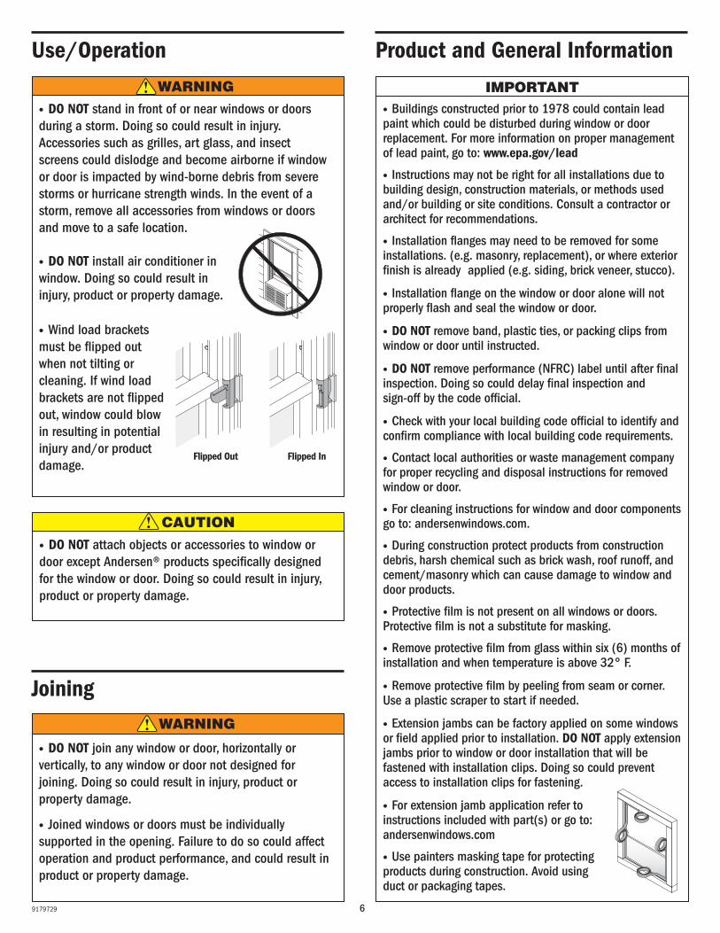
IMPORTANT· Buildings constructed prior to 1978 could contain lead paint which could be disturbed during window or door replacement. For more information on proper management of lead paint, go to: www.epa.gov/lead
· Instructions may not be right for all installations due to building design, construction materials, or methods used and/or building or site conditions. Consult a contractor or architect for recommendations.
· Installation flanges may need to be removed for some installations. (e.g. masonry, replacement), or where exterior finish is already applied (e.g. siding, brick veneer, stucco).
· Installation flange on the window or door alone will not properly flash and seal the window or door.
· DO NOT remove band, plastic ties, or packing clips from window or door until instructed.
· DO NOT remove performance (NFRC) label until after final inspection. Doing so could delay final inspection and sign-off by the code official.
· Check with your local building code official to identify and confirm compliance with local building code requirements.
· Contact local authorities or waste management company for proper recycling and disposal instructions for removed window or door.
· For cleaning instructions for window and door components go to: andersenwindows.com.
· During construction protect products from construction debris, harsh chemical such as brick wash, roof runoff, and cement/masonry which can cause damage to window and door products.
· Protective film is not present on all windows or doors. Protective film is not a substitute for masking.
· Remove protective film from glass within six (6) months ofinstallation and when temperature is above 32° F.
· Remove protective film by peeling from seam or corner. Use a plastic scraper to start if needed.
· Extension jambs can be factory applied on some windows or field applied prior to installation. DO NOT apply extension jambs prior to window or door installation that will be fastened with installation clips. Doing so could prevent access to installation clips for fastening.
· For extension jamb application refer to instructions included with part(s) or go to: andersenwindows.com
· Use painters masking tape for protecting products during construction. Avoid using duct or packaging tapes.
Use/Operation
· DO NOT stand in front of or near windows or doors during a storm. Doing so could result in injury. Accessories such as grilles, art glass, and insect screens could dislodge and become airborne if window or door is impacted by wind-borne debris from severe storms or hurricane strength winds. In the event of a storm, remove all accessories from windows or doors and move to a safe location.
· DO NOT install air conditioner inwindow. Doing so could result in injury, product or property damage.
· Wind load brackets must be flipped out when not tilting or cleaning. If wind load brackets are not flipped out, window could blow in resulting in potential injury and/or product damage.
· DO NOT attach objects or accessories to window or door except Andersen® products specifically designed for the window or door. Doing so could result in injury, product or property damage.
Product and General Information
· DO NOT join any window or door, horizontally or vertically, to any window or door not designed for joining. Doing so could result in injury, product or property damage.
· Joined windows or doors must be individually supported in the opening. Failure to do so could affect operation and product performance, and could result in product or property damage.
CAUTION
WARNING
WARNING
Flipped Out Flipped In
79179729
1
2
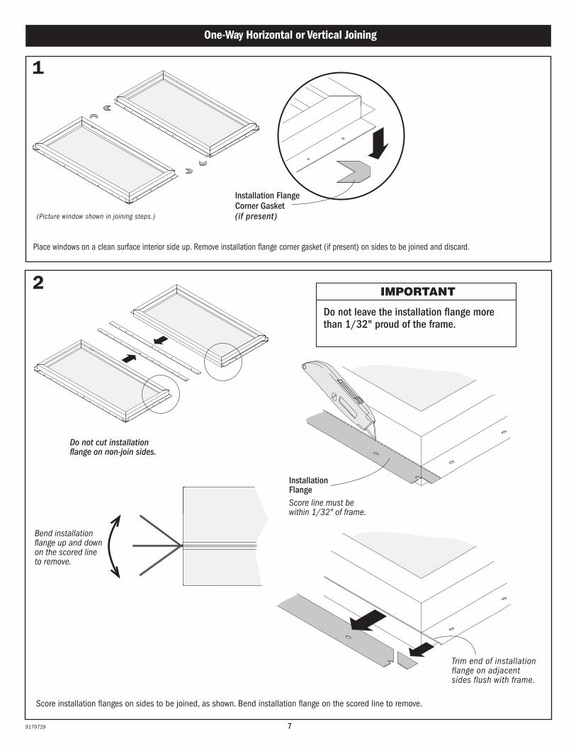
Place windows on a clean surface interior side up. Remove installation flange corner gasket (if present) on sides to be joined and discard.
(Picture window shown in joining steps.)
One-Way Horizontal or Vertical Joining
Trim end of installation flange on adjacent sides flush with frame.
IMPORTANT
Do not leave the installation flange more than 1/32" proud of the frame.
Score installation flanges on sides to be joined, as shown. Bend installation flange on the scored line to remove.
Do not cut installation flange on non-join sides.
Installation Flange
Bend installation flange up and down on the scored line to remove.
Score line must be within 1/32" of frame.
Installation Flange Corner Gasket(if present)
89179729
3
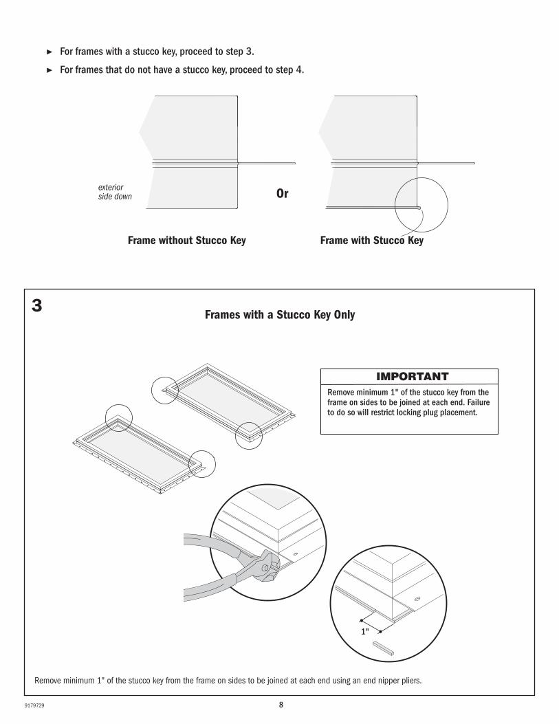
IMPORTANTRemove minimum 1" of the stucco key from the frame on sides to be joined at each end. Failure to do so will restrict locking plug placement.
▶ For frames with a stucco key, proceed to step 3.
▶ For frames that do not have a stucco key, proceed to step 4.
Remove minimum 1" of the stucco key from the frame on sides to be joined at each end using an end nipper pliers.
Frames with a Stucco Key Only
Frame with Stucco KeyFrame without Stucco Key
exterior side down Or
1"
99179729
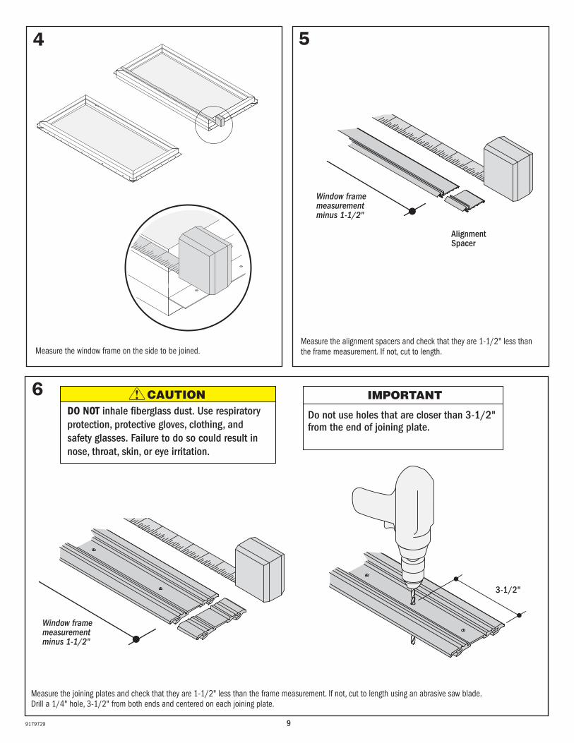
4
Measure the window frame on the side to be joined.
5
Measure the alignment spacers and check that they are 1-1/2" less than the frame measurement. If not, cut to length.
Alignment Spacer
Window frame measurement minus 1-1/2"
6
Measure the joining plates and check that they are 1-1/2" less than the frame measurement. If not, cut to length using an abrasive saw blade. Drill a 1/4" hole, 3-1/2" from both ends and centered on each joining plate.
3-1/2"
IMPORTANT
Do not use holes that are closer than 3-1/2" from the end of joining plate.
DO NOT inhale fiberglass dust. Use respiratory protection, protective gloves, clothing, and safety glasses. Failure to do so could result in nose, throat, skin, or eye irritation.
CAUTION
Window frame measurement minus 1-1/2"
109179729
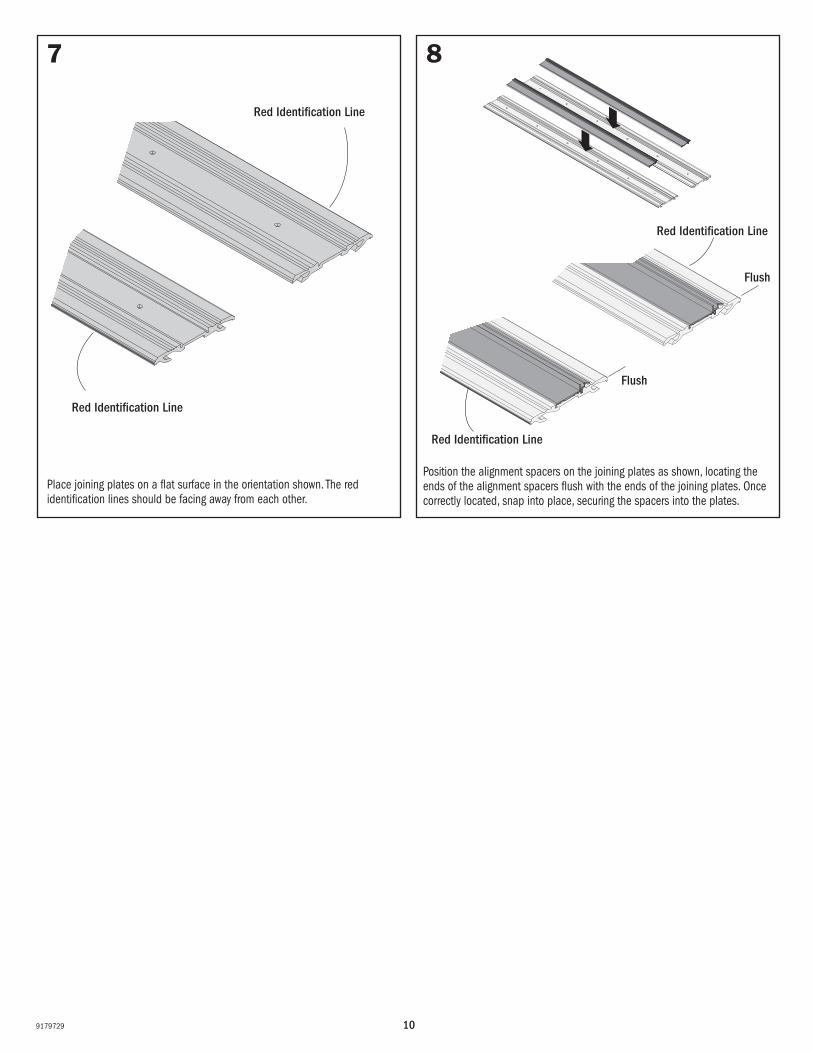
7
Place joining plates on a flat surface in the orientation shown. The red identification lines should be facing away from each other.
Red Identification Line
Red Identification Line
8
Position the alignment spacers on the joining plates as shown, locating the ends of the alignment spacers flush with the ends of the joining plates. Once correctly located, snap into place, securing the spacers into the plates.
Red Identification Line
Red Identification Line
Flush
Flush
119179729
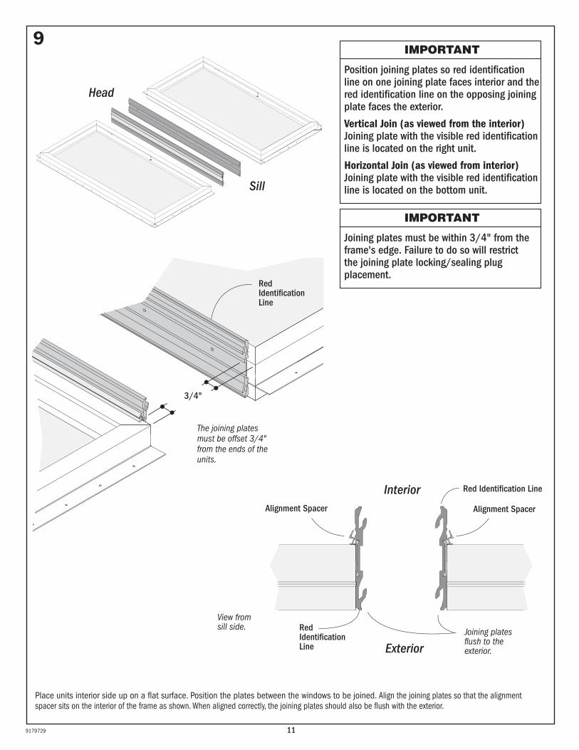
Place units interior side up on a flat surface. Position the plates between the windows to be joined. Align the joining plates so that the alignment spacer sits on the interior of the frame as shown. When aligned correctly, the joining plates should also be flush with the exterior.
9
Interior
ExteriorJoining plates flush to the exterior.
Red Identification Line
Red Identification Line
Alignment SpacerAlignment Spacer
3/4"
Red Identification Line
The joining plates must be offset 3/4" from the ends of the units.
IMPORTANT
Position joining plates so red identification line on one joining plate faces interior and the red identification line on the opposing joining plate faces the exterior.
Vertical Join (as viewed from the interior) Joining plate with the visible red identification line is located on the right unit.
Horizontal Join (as viewed from interior) Joining plate with the visible red identification line is located on the bottom unit.
IMPORTANT
Joining plates must be within 3/4" from the frame's edge. Failure to do so will restrict the joining plate locking/sealing plug placement.
Head
Sill
View from sill side.
129179729
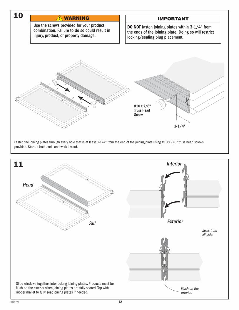
Fasten the joining plates through every hole that is at least 3-1/4" from the end of the joining plate using #10 x 7/8" truss head screws provided. Start at both ends and work inward.
10 IMPORTANT
DO NOT fasten joining plates within 3-1/4" from the ends of the joining plate. Doing so will restrict locking/sealing plug placement.
#10 x 7/8" Truss Head Screw
3-1/4"
Slide windows together, interlocking joining plates. Products must be flush on the exterior when joining plates are fully seated. Tap with rubber mallet to fully seat joining plates if needed.
11
Flush on the exterior.
WARNINGUse the screws provided for your product combination. Failure to do so could result in injury, product, or property damage.
Interior
Exterior
Views from sill side.
Head
Sill
139179729
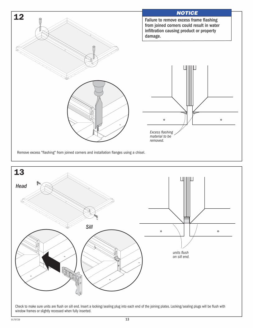
12
13
Check to make sure units are flush on sill end. Insert a locking/sealing plug into each end of the joining plates. Locking/sealing plugs will be flush with window frames or slightly recessed when fully inserted.
Excess flashing material to be removed.
Remove excess "flashing" from joined corners and installation flanges using a chisel.
units flush on sill end.
Head
Sill
NOTICEFailure to remove excess frame flashing from joined corners could result in water infiltration causing product or property damage.
149179729
15
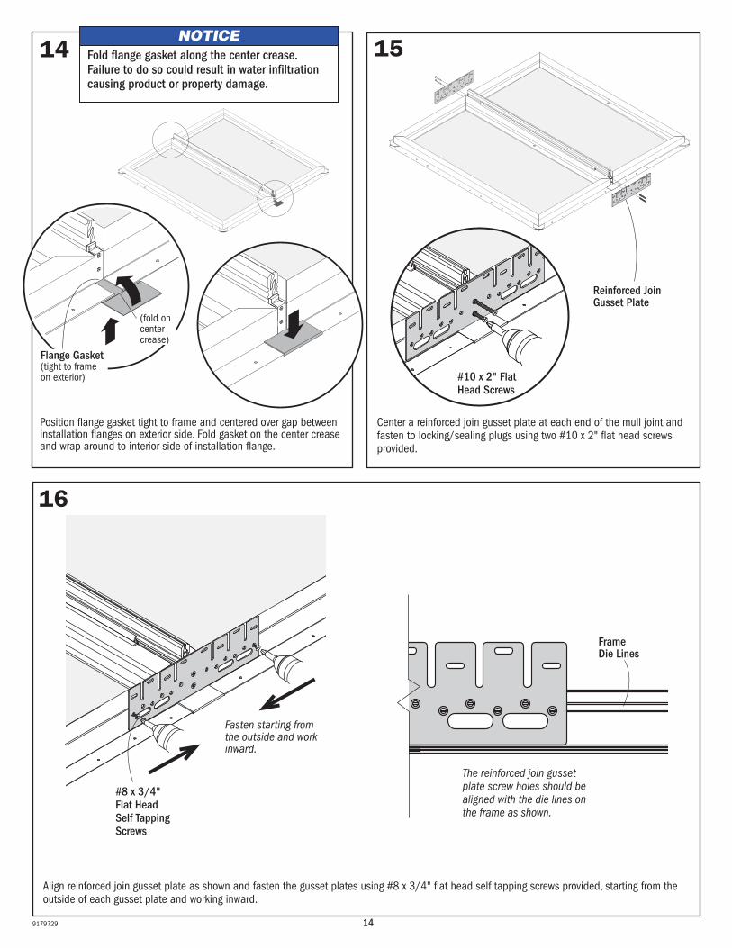
Center a reinforced join gusset plate at each end of the mull joint and fasten to locking/sealing plugs using two #10 x 2" flat head screws provided.
Reinforced Join Gusset Plate
16
Fasten starting from the outside and work inward.
Frame Die Lines
#10 x 2" Flat Head Screws
14
Position flange gasket tight to frame and centered over gap between installation flanges on exterior side. Fold gasket on the center crease and wrap around to interior side of installation flange.
Fold flange gasket along the center crease. Failure to do so could result in water infiltration causing product or property damage.
NOTICE
Flange Gasket(tight to frame on exterior)
(fold on center crease)
#8 x 3/4" Flat Head Self Tapping Screws
Align reinforced join gusset plate as shown and fasten the gusset plates using #8 x 3/4" flat head self tapping screws provided, starting from the outside of each gusset plate and working inward.
The reinforced join gusset plate screw holes should be aligned with the die lines on the frame as shown.
159179729
18
19
17
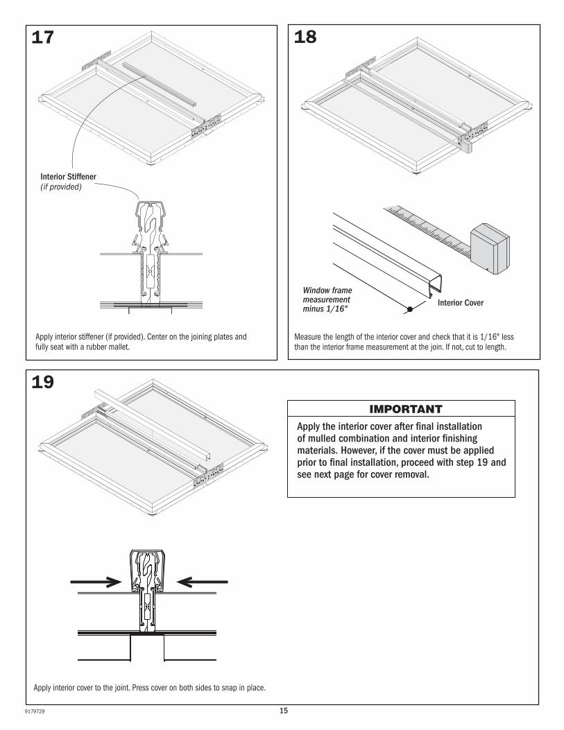
IMPORTANTApply the interior cover after final installation of mulled combination and interior finishing materials. However, if the cover must be applied prior to final installation, proceed with step 19 and see next page for cover removal.
Measure the length of the interior cover and check that it is 1/16" less than the interior frame measurement at the join. If not, cut to length.
Apply interior cover to the joint. Press cover on both sides to snap in place.
Interior Cover
Apply interior stiffener (if provided). Center on the joining plates and fully seat with a rubber mallet.
Interior Stiffener(if provided)
Window frame measurement minus 1/16"
169179729
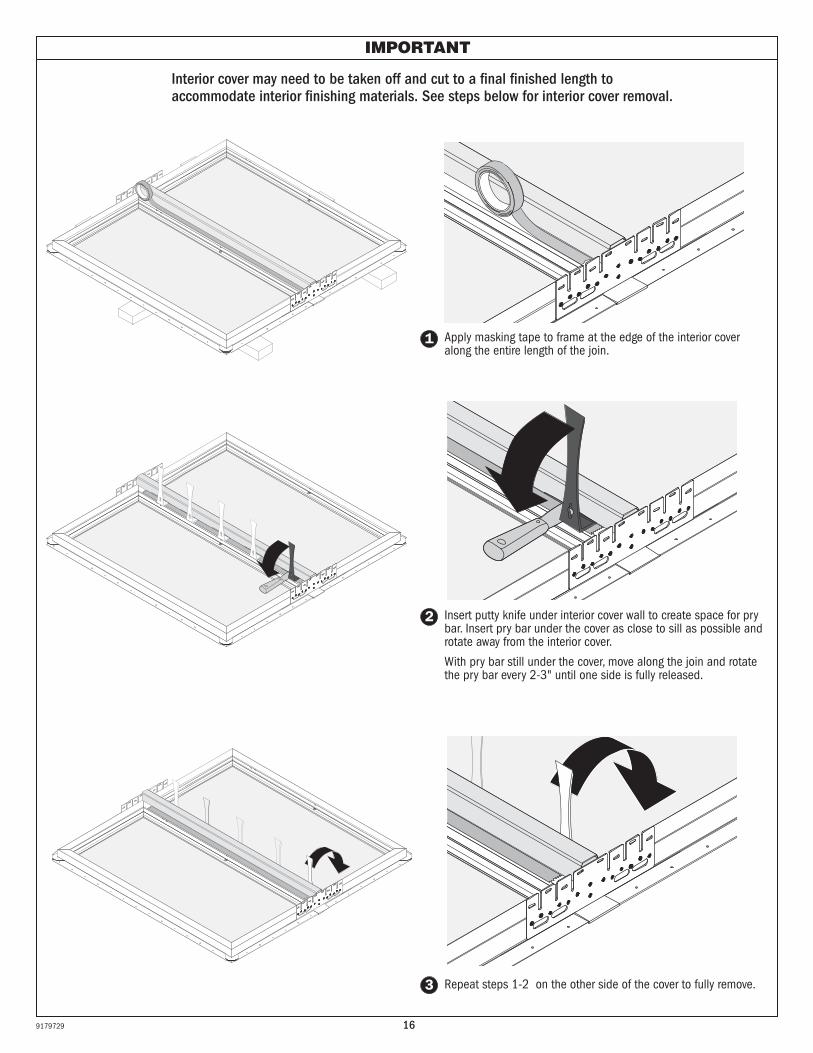
IMPORTANT
Interior cover may need to be taken off and cut to a final finished length to accommodate interior finishing materials. See steps below for interior cover removal.
1 Apply masking tape to frame at the edge of the interior cover along the entire length of the join.
2 Insert putty knife under interior cover wall to create space for pry bar. Insert pry bar under the cover as close to sill as possible and rotate away from the interior cover.
With pry bar still under the cover, move along the join and rotate the pry bar every 2-3" until one side is fully released.
3 Repeat steps 1-2 on the other side of the cover to fully remove.
179179729
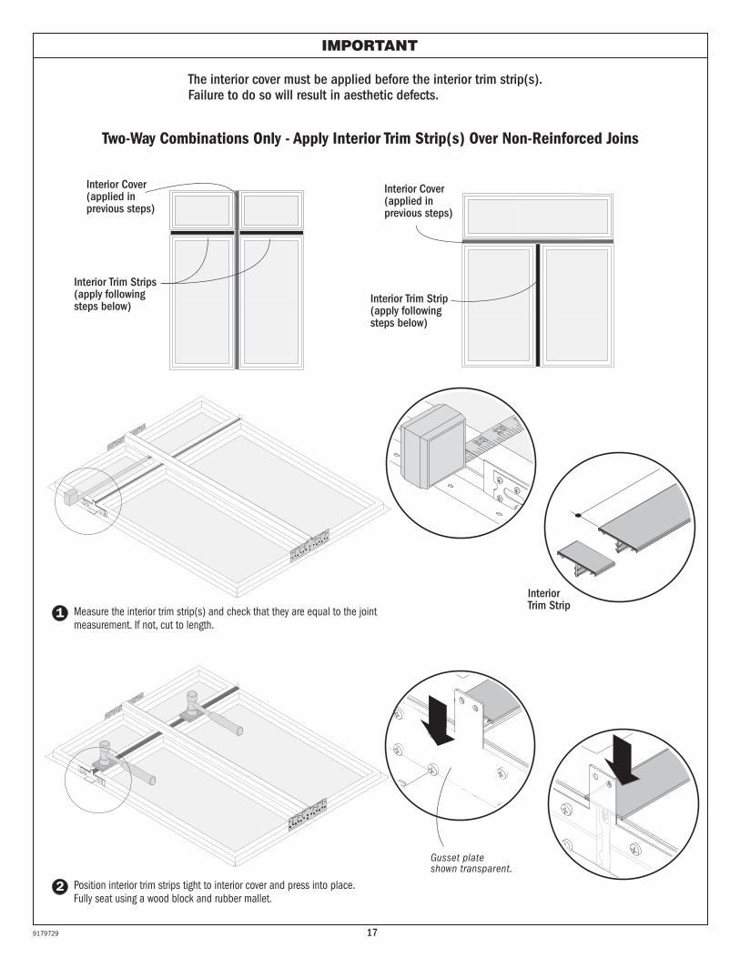
Two-Way Combinations Only - Apply Interior Trim Strip(s) Over Non-Reinforced Joins
1
2
Interior Trim Strip
Position interior trim strips tight to interior cover and press into place. Fully seat using a wood block and rubber mallet.
Gusset plate shown transparent.
Interior Cover (applied in previous steps)
Interior Cover (applied in previous steps)
Interior Trim Strips(apply following steps below)
Interior Trim Strip(apply following steps below)
Measure the interior trim strip(s) and check that they are equal to the joint measurement. If not, cut to length.
IMPORTANT
The interior cover must be applied before the interior trim strip(s). Failure to do so will result in aesthetic defects.
189179729
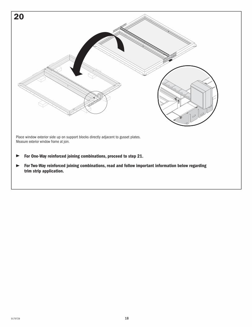
20
Place window exterior side up on support blocks directly adjacent to gusset plates. Measure exterior window frame at join.
For One-Way reinforced joining combinations, proceed to step 21.
For Two-Way reinforced joining combinations, read and follow important information below regarding trim strip application.
199179729
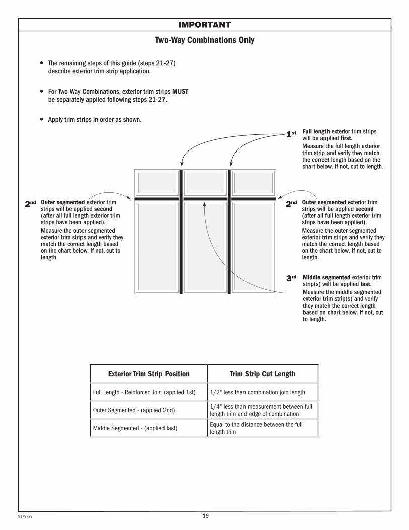
Two-Way Combinations Only
For Two-Way Combinations, exterior trim strips MUST be separately applied following steps 21-27.
The remaining steps of this guide (steps 21-27) describe exterior trim strip application.
IMPORTANT
Apply trim strips in order as shown.
1st
3rd
2nd
Full length exterior trim strips will be applied first.Measure the full length exterior trim strip and verify they match the correct length based on the chart below. If not, cut to length.
Middle segmented exterior trim strip(s) will be applied last.Measure the middle segmented exterior trim strip(s) and verify they match the correct length based on chart below. If not, cut to length.
Outer segmented exterior trim strips will be applied second (after all full length exterior trim strips have been applied). Measure the outer segmented exterior trim strips and verify they match the correct length based on the chart below. If not, cut to length.
2nd Outer segmented exterior trim strips will be applied second (after all full length exterior trim strips have been applied). Measure the outer segmented exterior trim strips and verify they match the correct length based on the chart below. If not, cut to length.
Exterior Trim Strip Position Trim Strip Cut Length
Full Length - Reinforced Join (applied 1st) 1/2" less than combination join length
Outer Segmented - (applied 2nd) 1/4" less than measurement between full length trim and edge of combination
Middle Segmented - (applied last) Equal to the distance between the full length trim
209179729
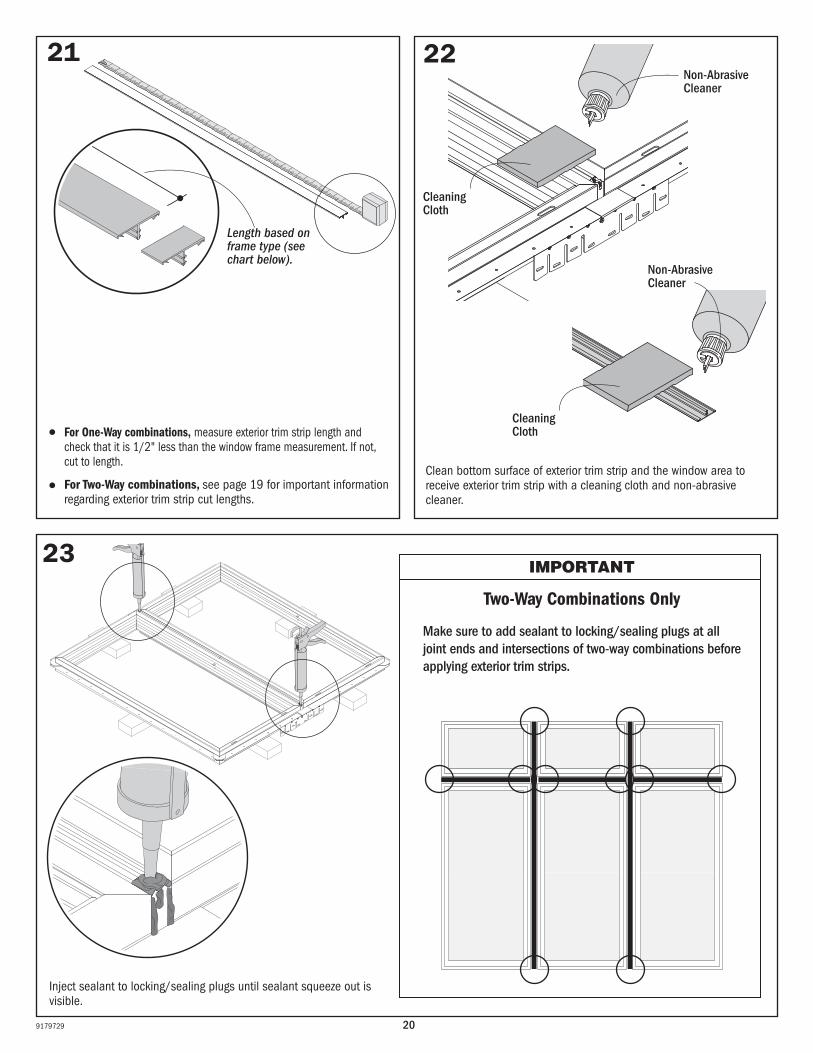
Inject sealant to locking/sealing plugs until sealant squeeze out is visible.
23
2221
Two-Way Combinations Only
IMPORTANT
Make sure to add sealant to locking/sealing plugs at all joint ends and intersections of two-way combinations before applying exterior trim strips.
Clean bottom surface of exterior trim strip and the window area to receive exterior trim strip with a cleaning cloth and non-abrasive cleaner.
For One-Way combinations, measure exterior trim strip length and check that it is 1/2" less than the window frame measurement. If not, cut to length.
For Two-Way combinations, see page 19 for important information regarding exterior trim strip cut lengths.
Cleaning Cloth
Non-Abrasive Cleaner
Cleaning Cloth
Non-Abrasive Cleaner
Length based on frame type (see chart below).
219179729
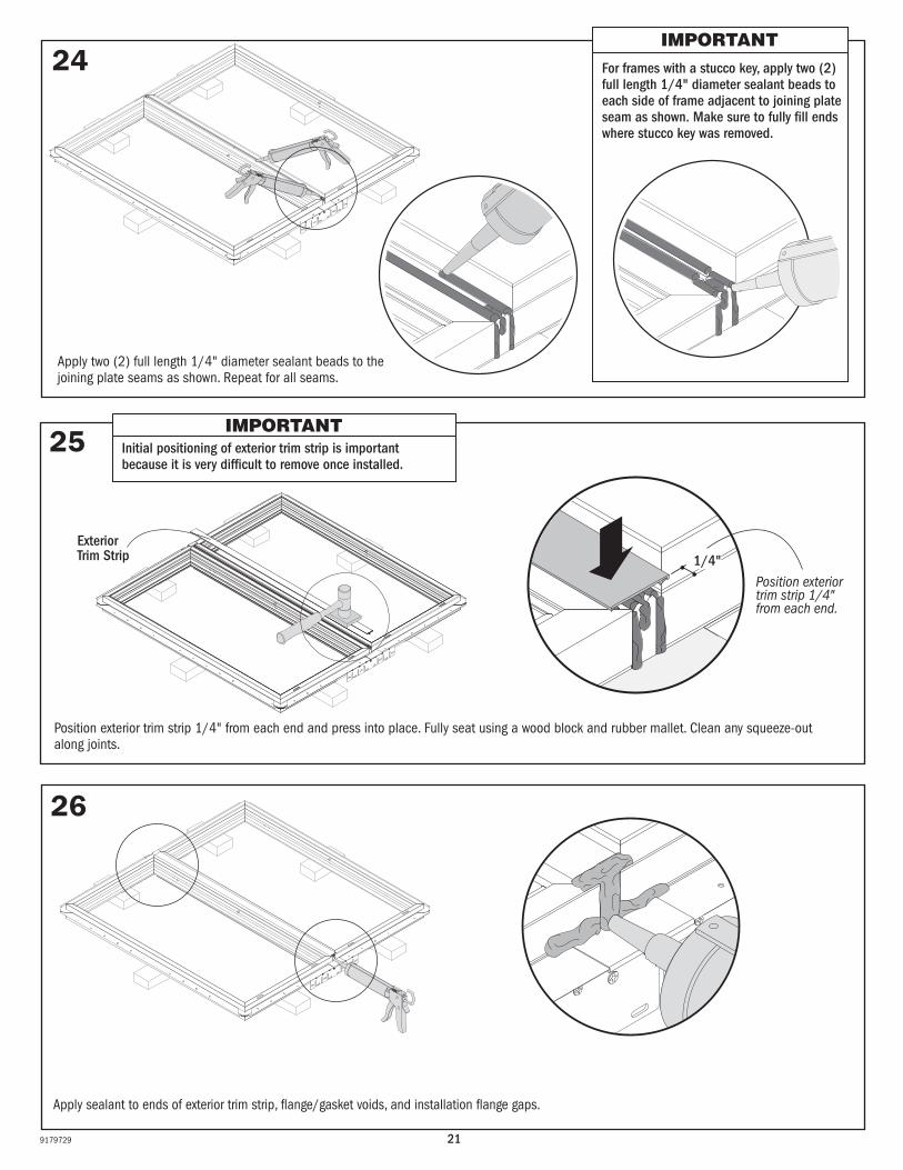
24
Position exterior trim strip 1/4" from each end and press into place. Fully seat using a wood block and rubber mallet. Clean any squeeze-out along joints.
25
Position exterior trim strip 1/4" from each end.
26
1/4"
Initial positioning of exterior trim strip is important because it is very difficult to remove once installed.
IMPORTANT
Exterior Trim Strip
IMPORTANTFor frames with a stucco key, apply two (2) full length 1/4" diameter sealant beads to each side of frame adjacent to joining plate seam as shown. Make sure to fully fill ends where stucco key was removed.
Apply two (2) full length 1/4" diameter sealant beads to the joining plate seams as shown. Repeat for all seams.
Apply sealant to ends of exterior trim strip, flange/gasket voids, and installation flange gaps.
22 9179729
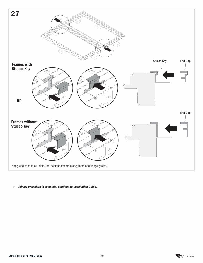
▶ Joining procedure is complete. Continue to Installation Guide.
Frames with Stucco Key
27
Apply end caps to all joints. Tool sealant smooth along frame and flange gasket.
End Cap
Frames without Stucco Key
or
Stucco Key
End Cap