Embed Size (px)
Citation preview
Código code
TipoType
Sensibilidad (A) Sensivity
Retardo disparo (s) Tripping delay
P14035 WRU-10 0,03-0,1-0,3-0,5-1-3 por ajuste directo/by direct setting
5-10-30 por/by SETUPINS-SEL-0,02-0,1-0,2-0,3-0,4-0,5-0,75-1 por ajuste directo / by direct setting
3-5-10 por/by SETUP
Relé de protección diferencial electrónico WRU-10WRU-10 Electronic Earth-leakage Protection Relay
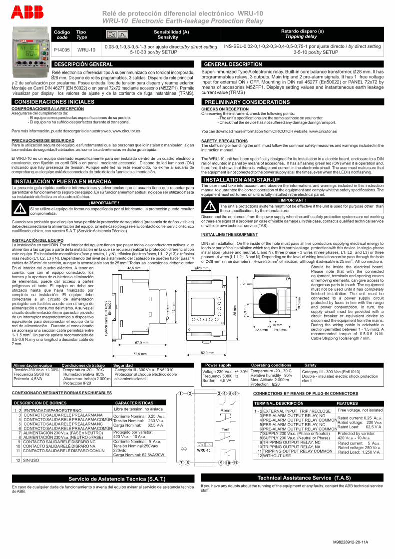
Relé electronico diferencial tipo A superinmunizado con toroidal incorporado, 28 mm. Dispone de relés programables, 3 salidas. Disparo de relé principal
y 2 de señalización por prealarma. Posee entrada libre de tensión para disparo y rearme exterior. Montaje en Carril DIN 46277 (EN 50022) o en panel 72x72 mediante accesorio (M5ZZF1). Permite visualizar por display los valores de ajuste y de la corriente de fuga instantánea (TRMS).
M98228912-20-11A
CONSIDERACIONES INICIALESCOMPROBACIONES A LA RECEPCIÓNAsegurarse del cumplimiento de: - El equipo corresponde a las especificaciones de su pedido. - El equipo no ha sufrido desperfectos durante el transporte.
Para más información, puede descargarla de nuestra web, www.circutor.es
PRECAUCIONES DE SEGURIDADPara la utilización segura del equipo, es fundamental que las personas que lo instalen o manipulen, sigan las medidas de seguridad habituales, así como las advertencias en dicha guía rápida.
El WRU-10 es un equipo diseñado específicamente para ser instalado dentro de un cuadro eléctrico o envolvente, con fijación en carril DIN o en panel mediante accesorio. Dispone de led luminoso (ON) indicando que hay presencia de tensión. Aunque este led no esté encendido, no exime al usuario de comprobar que el equipo está desconectado de toda de toda fuente de alimentación.
INSTALACIÓN Y PUESTA EN MARCHA
¡ IMPORTANTE !
!
DESCRIPCIÓN GENERAL
Si se utiliza el equipo de forma no especificada por el fabricante, la protección puede resultar comprometida.
La presente guía rápida contiene informaciones y advertencias que el usuario tiene que respetar para garantizar el funcionamiento seguro del equipo. En su funcionamiento habitual no debe ser utilizado hasta su instalación definitiva en el cuadro eléctrico.
Cuando sea probable que el equipo haya perdido la protección de seguridad (presencia de daños visibles) debe desconectarse la alimentación del equipo. En este caso póngase enc contacto con el servicio técnico cualificado, o bien, con nuestro S.A.T. (Servicio Asistencia Técnica).
INSTALACIÓN DEL EQUIPOLa instalación en carril DIN. Por el interior del agujero tienen que pasar todos los conductores activos que alimentan a las cargas o parte de la instalación en la que se requiera realizar la protección diferencial con este equipo. En instalación monofásica (fase y neutro, L y N), trifásica (las tres fases, L1,L2 yL3) o trifásica mas neutro (L1, L2, L3 y N). Dependiendo del nivel de aislamiento del cableado se pueden hacer pasar 4
2 2cables de 35 mm de sección, aunque lo aconsejable son de 25 mm . Todas las conexiones deben quedar
Tensión 230 Vc.a. +/- 30% Temperatura -20 ... 70 C Categoria III - 300 Vc.a. EN61010 Frecuencia 50/60 Hz Humedad relativa 95% Protección al choque eléctrico doble Potencia 4,5 VA Altura max. trabajo 2.000 m aislamiento clase II
Protección IP20
CONEXIONADO MEDIANTE BORNAS ENCHUFABLES
1 - 2 ENTRADA DISPARO EXTERNO3 CONTACTO SALIDA RELÉ PREALARMA NA4 CONTACTO SALIDA RELÉ PREALARMA COMÚN5 CONTACTO SALIDA RELÉ PREALARMA NC6 CONTACTO SALIDA RELÉ PREALARMA COMÚN7 ALIMENTACIÓN 230 Vc.a. (FASE o NEUTRO)8 ALIMENTACIÓN 230 Vc.a. (NEUTRO o FASE)
9 CONTACTO SALIDA RELÉ DISPARO NC 10 CONTACTO SALIDA RELÉ DISPARO NA 11 CONTACTO SALIDA RELÉ DISPARO COMÚN
12 SIN USO
Alimentacion equipo Condiciones de trabajo Seguridad
DESCRIPCION BORNES CARACTERISTICAS
Corriente Nominal: 5 Ac.a.
Tensión Nominal:250Vac/220vdc Carga Nominal: 62.5VA/30W
Corriente Nominal: 0,25 Ac.a.
Tensión Nominal: 230 Vc.a. Carga Nominal: 62,5 V·A
Libre de tension, no aislada
Protegido por varistor: 420 Vc.a. - 10 Ac.a.
Servicio de Asistencia Técnica (S.A.T.)
En caso de cualquier duda de funcionamiento o averia del equipo avisar al servicio de asistencia tecnica de ABB.
DESCRIPCIÓN DE BORNES CARACTERÍSTICAS
Super-inmunized Type A electronic relay. Built-in core balance transformer, 28 mm. It has programmables relays, 3 outputs. Main trip and 2 pre-alarm signals. It has 1 free voltage input for external ON / OFF. Mounting in DIN rail 46277 (En50022) or PANEL 72x72 by means of accesories M5ZFF1. Displays setting values and instantaneous earth leakage current value (TRMS)
GENERAL DESCRIPTION
PRELIMINARY CONSIDERATIONSCHECKS ON RECEPTIONOn receving the instrument, check the following points: - The unit’s specifications are the same as those on your order. - Check that the device has not suffered any damage during transport.
You can download more information from CIRCUTOR website, www.circutor.es
SAFETY PRECAUTIONSThe staff using or handling the unit must follow the common safety measures and warnings included in the instruction manual.
The WRU-10 unit has been specifically designed for its installation in a electric board, enclosure to a DIN rail or mounted in panel by means of accesories. It has a flashing green led (ON) when it is operation and, therefore, it shows that there is voltage and current in the electronic circuit. The user must make sure that the equipment is not conected to the power supply at all the times, even when the LED is not flashing.
The user must take into account and observe the informations and warnings included in this instruction manual to guarantee the correct operation of the equipment and comply whit the safety specifications. The equipment must not turned on until is fully installed in the electrical panel.
Disconnect the equipment from the power supply when the unit´ssafety protection systems are not working or there are signs of a problem (in case of visible damage). In this case, contact a qualified technical service or with our own technical service (TAS).
INSTALLING THE EQUIPMENT
DIN rail installation. On the inside of the hole must pass all live conductors supplyng electrical energy to loads or part of the installation which requires it to earth leakage protection with this device. In single-phase installation (phase and neutral, L and N), three phase - 3 wires (three phases, L1, L2 and L3) or three phases - 4 wires (L1, L2, L3 and N). Depending on the level of wiring insulation can be pass through the hole
2 2of 28 mm (inner diameter) 4-wire 35 mm of section, although it advisable is 25 mm . All connections
INSTALLATION AND STAR-UP
¡ IMPORTANT !
! The unit´s protections systems might not be effective if the unit is used for purpose other than those specifications by the manufacturer.
En el interior del cuadro eléctrico. A tener en cuenta, que con el equipo conectado, los bornes y la apertura de cubiertas o eliminación de elementos, puede dar acceso a partes peligrosas al tacto. El equipo no debe ser utilizado hasta que haya finalizado por completo su instalación. El equipo debe conectarse a un circuito de alimentación protegido con fusibles acorde con el rango de alimentación y consumo del mismo. A su vez el circuito de alimentación tiene que estar provisto de un interruptor magnetotermico o dispositivo equivalente para desconectar el equipo de la red de alimentación. Durante el conexionado se aconseja una sección cable permitida entre
21- 1.5 mm . Un par de apriete recomendado de 0,5-0,6 N.m y una longitud a desaislar cable de 7 mm.
Should be inside the electrical board. Please note that with the connected equipment, terminals and opening covers or removing elements, can give access to dangerous parts to touch. The equipment must not be used until it has completely finished installation. The unit must be connected to a power supply circuit protected by fuses in line with the range and power consumption. In turn, the supply circuit must be provided with a circuit breaker or equivalent device to disconnect the equipment from the mains. During the wiring cable is advisable a section permitted between 1 - 1.5 mm2. A recommended torque of 0.5-0.6 N.M. Cable Stripping Tools length 7 mm.
Power supply Operating conditions Safety
Category III - 300 Vac (En61010)Double - insulated electric shock protection clas II
Voltage 230 Va.c..Frequency 50!60 HzBurden 4,5 VA
+/- 30% Temperature -20...70 CRelative humidity 95%Max. Altitude 2.000 mProtection Ip20
CONNECTIONS BY MEANS OF PLUG-IN CONNECTORS
Rated current: 5 Ac.a.
Rated voltage: 250 Vc.a. Rated Load: 1.250 V·A
Rated current: 0,25 Ac.a.
Rated voltage: 230 Vc.a. Rated Load: 62,5 V·A
Free voltage, not isolated
Protected by varistor: 420 Vc.a. - 10 Ac.a.
TERMINAL DESCRIPCIÓN FEATURES
1 - 2 EXTERNAL INPUT TRIP / RECLOSE 3 PRE-ALARM OUTPUT RELAY, NO 4 PRE-ALARM OUTPUT RELAY COMMON 5 PRE-ALARM OUTPUT RELAY, NC 6 PRE-ALARM OUTPUT RELAY COMMON 7 SUPPLY 230 Va.c. (Phase or Neutral) 8 SUPPLY 230 Va.c. (Neutral or Phase) 9 TRIPPING OUTPUT RELAY, NC 10 TRIPPING OUTPUT RELAY, NA 11 TRIPPING OUTPUT RELAY COMMON 12 WITHOUT USE
Technical Assistance Service (T.A.S)
If you have any doubts about the running of the equipment or any faults, contact the ABB technical service staff.
RG
U -
10 C
Con el pulsador navegamos por los submenús y con el pulsador vamos visualizando los valores a escoger. Validamos el valor pulsando
, se visualiza “SAVE” y salimos del SETUP. Con el teclado inactivo el equipo automáticamente sale del modo de programación visualizando “EXIT” sin cambiar la configuración.
PROG
PROG
Puls
ador
Pulsador PROG
FREC
LIM
Puls
ador 50 Hz
60 Hz
10 s, 30 A
1 s, 3 A
PROG
+
REC
PROG
ESQUEMAS DE CONEXIÓN / WIRING DIAGRAM
Relé de protección diferencial electrónico WRU-10WRU-10 Electronic Earth-leakage Protection Relay
M98228912-20-11A
- . .
- . .
- BY TRIP.
l. - BY PREALARM.
.
( t , I and std/+ )d d
- , t . d
td
. SAVE.
- , I . I . d d
- , std/+.
.
( t , I , std/+ and Auto)d d
. - , t . d
- , I . Sd
(OFF-50-60-70-80-MAIN). - , std/+. S .- , Auto. A
.
SETUP A
.
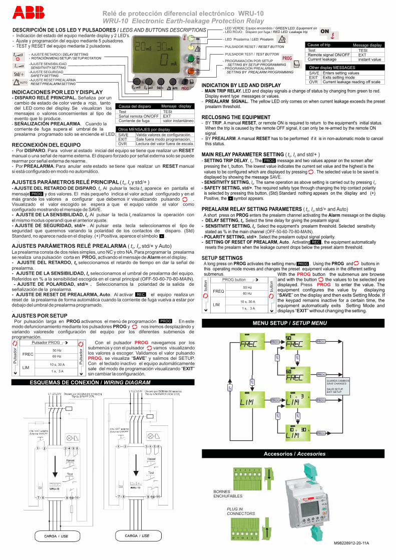
INDICATION BY LED AND DISPLAYMAIN TRIP RELAY LED and display signals a change of status by changing from green to red.
Display event type messages or valuesPREALARM SIGNAL. The yellow LED only comes on when current leakage exceeds the preset
prealarm threshold
RECLOSING THE EQUIPMENTA manual RESET, or remote ON is required to return to the equipment's initial status.
When the trip is caused by the remote OFF signal, it can only be re-armed by the remote ON signa
A manual RESET has to be performed if it is in non-automatic mode to cancel this status
MAIN RELAY PARAMETER SETTING SETTING TRIP DELAY The message and two values appear on the screen after
pressing the button. The lowest value indicates the current set value and the highest is the values to be configured which are displayed by pressing The selected value to be saved is displayed by showing the message
SENSITIVITY SETTING The same operation as above setting is carried out by pressing SAFETY SETTING The required safety type through changing the trip contact polarity
is selected by pressing this button. (Std) Standard nothing appears on the display and (+) Positive, the symbol appears
PREALARM RELAY SETTING PARAMETERS A short press on PROG enters the prealarm channel activating the Alarm message on the displayDELAY SETTING . Select the time delay for giving the prealarm signalSENSITIVITY SETTING elect the equipment's prealarm threshold. Selected sensitivity
stated as % in the main channelPOLARITY SETTING elect the prealarm output signal polaritySETTING OF RESET OF PREALARM ctivating , the equipment automatically
resets the prealarm when the leakage current drops below the preset alarm threshold
SETTINGSlong press on PROG activates the setting menu . Using the PROG and buttons in
this operating mode moves and changes the preset equipment values in the different setting submenus
DESCRIPCIÓN DE LOS LED Y PULSADORES / LEDS AND BUTTONS DESCRIPTIONS- Indicación del estado del equipo mediante display y 2 LED’s.- Ajuste y programación del equipo mediante 5 pulsadores.- TEST y RESET del equipo mediante 2 pulsadores.
PROG
- AJUSTE RETARDO / DELAY SETTING- ROTACIÓN MENÚ SETUP / SETUP ROTATION
AUTO- - AJUSTE RESET PREALARMA
RESET PREALARM SETTING
- AJUSTE SENSIBILIDAD SENSITIVITY SETTING
- AJUSTE SEGURIDADSAFETY SETTING
Otros MENSAJES por display
SAVEEXITOVR
Valida valores de configuración.Sale fuera modo programación.Lectura del valor fuera de escala.
Causa del disparo Mensaje display
TestSeñal remota ON/OFFCorriente de fuga
TEStEXTvalor instantáneo
- LED VERDE: Equipo encendido / - LED ROJO: Disparo por fuga /
- LED Prealarma /
- PULSADOR RESET /
- PULSADOR TEST /
GREEN LED: Equipment onRED LED: Leakage trip
LED: Prealarm
RESET BUTTON
TEST BUTTON
- PROGRAMACIÓN POR SETUP - PROGRAMACIÓN PREALARMA
SETTING BY SETUP PROGRAMMING
SETTING BY PREALARM PROGRAMMING
Id
Cause of trip Message display
TestRemote signal ON/OFFCurrent leakage
TEStEXTinstant value
Other display MESSAGES
SAVEEXITOVR
Enters setting valuesExits setting modeCurrent leakage reading off scale
button PROG button
FREQ
LIM
button
50 Hz
60 Hz
10 s, 30 A
1 s, 3 A
mS mA
mA
PROG
mS mA
mA
PROG
mS mA
mA
PROG
mS mA
mA
PROG
mS mA
mA
PROG
mS mA
mA
PROG
td
td
PROG
PROG
PROG
PROG
tdtd
tdtd
PROG
PROG
GUARDA CAMBIOS SAVE CHANGES
SALIR SETUP EXIT SETUP
MENU SETUP / SETUP MENU
REC
+
PROG
INDICACIONES POR LED Y DISPLAY- DISPARO RELÉ PRINCIPAL. Señaliza por un cambio de estado de color verde a rojo, tanto del LED como del display. Se visualizan los mensajes o valores concernientes al tipo de evento que lo produce.- SEÑALIZACIÓN PREALARMA. Cuando la corriente de fuga supera el umbral de la prealarma programado solo se enciende el LED.
RECONEXIÓN DEL EQUIPO- Por DISPARO. Para volver al estado inicial del equipo se tiene que realizar un RESET manual o una señal de rearme externa. El disparo forzado por señal externa solo se puede rearmar por señal externa de rearme.- Por PREALARMA. Para anular este estado se tiene que realizar un RESET manual si está configurado en modo no automático.
AJUSTES PARÁMETROS RELÉ PRINCIPAL ( t , I y std/+ )d d
- AJUSTE DEL RETARDO DE DISPARO, t . Al pulsar la tecla t aparece en pantalla el d d
mensaje y dos valores. El más pequeño indica el valor actual configurado y en el más grande los valores a configurar que debemos ir visualizando pulsando . Visualizado el valor escogido se espera a que el equipo valide el valor como configurado mostrando el mensaje de SAVE.- AJUSTE DE LA SENSIBILIDAD, I . Al pulsar la tecla I realizamos la operación con d d
el mismo modus operandi que el anterior ajuste.- AJUSTE DE SEGURIDAD, std/+ . Al pulsar esta tecla seleccionamos el tipo de seguridad que queremos variando la polaridad de los contactos de disparo. (Std) Standard, no aparece nada en el display. (+) Positiva, aparece el símbolo . .AJUSTES PARÁMETROS RELÉ PREALARMA ( t , I , std/+ y Auto)d d
La prealarma consta de dos reles simples, uno NC y otro NA. Para programar la prealarma se realiza una pulsación corta en , activando el mensaje de Alarm en el display.- AJUSTE DEL RETARDO, t seleccionamos el retardo de tiempo en dar la señal de d
prealarma.- AJUSTE DE LA SENSIBILIDAD, I seleccionamos el umbral de prealarma del equipo. d
Referidos en % a la sensibilidad escogida en el canal principal (OFF-50-60-70-80-MAIN). - AJUSTE DE POLARIDAD, std/+ . Seleccionamos la polaridad de la salida de señalización de la prealarma.- AJUSTE DE RESET DE PREALARMA, Auto. Al activar el equipo realiza un reset de la prealarma de forma automática cuando la corriente de fuga vuelva a estar por debajo del umbral de prealarma programado..AJUSTES POR SETUP Por pulsación larga en PROG activamos el menú de programación . En este modo defuncionamiento mediante los pulsadores PROG y nos iremos desplazándo y variando valoresde configuración del equipo por los diferentes submenús de programación.
PROG
With the button the submenus are browse and with the button the values to be selected are displayed to enter the value. The equipment configures the value by displaying
on the display and then exits Setting Mode. If the keypad remains inactive for a certain time, the equipment automatically exits Setting Mode and displays without changing the setting
. Press
“SAVE”
“EXIT” .
PROG
PROG
Accesorios / Accesories
BORNESENCHUFABLES
PLUG INCONNECTORS