Embed Size (px)
Citation preview
Interfaces to injection molding
and structural FEA codes for the
accurate prediction of composite
materials and reinforced platics
parts performance using non-
linear multi-scale modeling
technology.
For the accurate prediction of the
local/global nonlinear behavior of
multi-phase materials using FEA of
realistic Representative Volume
Element (RVE).
For the preparation, storage,
retrieval and secure exchange of
DIGIMAT material models between
material suppliers and users, while
protecting Intellectual Property.
For the efficient mapping of data
scalar & tensor data between
dissimilar Shell and 3D FE meshes.
For an easy and efficient design of
honeycomb sandwich panels using
state-of-the-art micromechanical
material modeling technology.
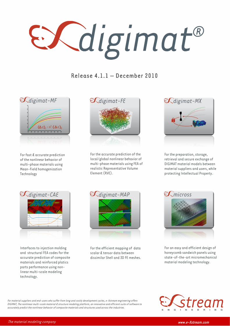
Release 4.1.1 – December 2010
For material suppliers and end-users who suffer from long and costly development cycles, e-Xstream engineering offers
DIGIMAT, The nonlinear multi-scale material & structure modeling platform, an innovative and efficient suite of software to
accurately predict the nonlinear behavior of composite materials and structures used across the industries.
The material modeling company www.e-Xstream.com
For fast & accurate prediction
of the nonlinear behavior of
multi-phase materials using
Mean-Field homogenization
Technology
Homogenization Methods
Mori-Tanaka
Interpolative double inclusion
1st and 2nd order homogenization schemes
Multi-step, multi-level homogenization methods
High quality ODF reconstruction method: Orthotropic method
DIGIMAT; The nonlinear multi-scale material & structure modeling platform
NEW IN DIGIMAT 4.1
Thermo-elastoplastic & thermo-elastoviscoplastic material models
Viscoelastic-viscoplastic material models insensitive to time steps
Transversely isotropic and orthotropic Ohm & Fourier laws
Improved discretization scheme of the orientation distribution function (ODF)
GUI improvements:
- Redesign of failure indicator definition
- Redesign of piece-wise linear function capability
- 2D plots( Probing, grid, box zoom), Histogram capabilities
New GUI functionalities
User defined outputs
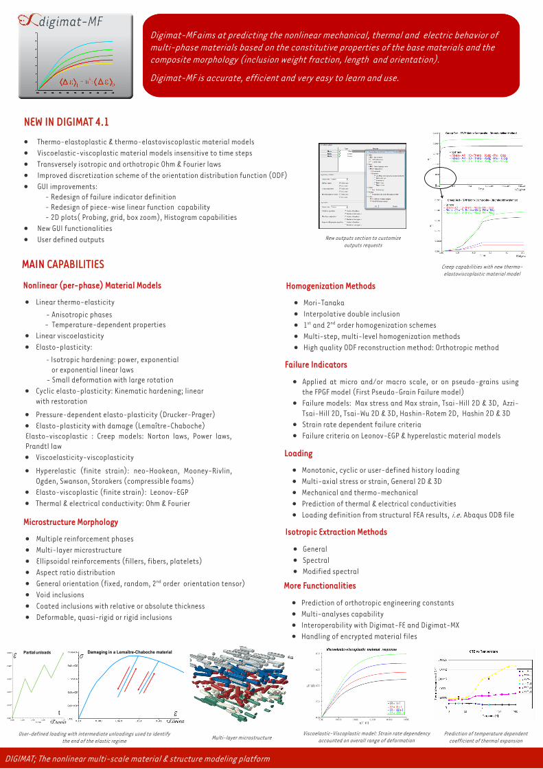
Digimat-MF aims at predicting the nonlinear mechanical, thermal and electric behavior of
multi-phase materials based on the constitutive properties of the base materials and the
composite morphology (inclusion weight fraction, length and orientation).
Digimat-MF is accurate, efficient and very easy to learn and use.
MAIN CAPABILITIES
Nonlinear (per-phase) Material Models
Linear thermo-elasticity
- Anisotropic phases
- Temperature-dependent properties
Linear viscoelasticity
Elasto-plasticity:
- Isotropic hardening: power, exponential
or exponential linear laws
- Small deformation with large rotation
Cyclic elasto-plasticity: Kinematic hardening; linear
with restoration
Pressure-dependent elasto-plasticity (Drucker-Prager)
Elasto-plasticity with damage (Lemaître-Chaboche)
Elasto-viscoplastic : Creep models: Norton laws, Power laws,
Prandtl law
Viscoelasticity-viscoplasticity
Hyperelastic (finite strain): neo-Hookean, Mooney-Rivlin,
Ogden, Swanson, Storakers (compressible foams)
Elasto-viscoplastic (finite strain): Leonov-EGP
Thermal & electrical conductivity: Ohm & Fourier
Microstructure Morphology
Multiple reinforcement phases
Multi-layer microstructure
Ellipsoidal reinforcements (fillers, fibers, platelets)
Aspect ratio distribution
General orientation (fixed, random, 2nd order orientation tensor)
Void inclusions
Coated inclusions with relative or absolute thickness
Deformable, quasi-rigid or rigid inclusions
Isotropic Extraction Methods
General
Spectral
Modified spectral
Loading
Monotonic, cyclic or user-defined history loading
Multi-axial stress or strain, General 2D & 3D
Mechanical and thermo-mechanical
Prediction of thermal & electrical conductivities
Loading definition from structural FEA results, i.e. Abaqus ODB file
Failure Indicators
Applied at micro and/or macro scale, or on pseudo-grains using
the FPGF model (First Pseudo-Grain Failure model)
Failure models: Max stress and Max strain, Tsai-Hill 2D & 3D, Azzi-
Tsai-Hill 2D, Tsai-Wu 2D & 3D, Hashin-Rotem 2D, Hashin 2D & 3D
Strain rate dependent failure criteria
Failure criteria on Leonov-EGP & hyperelastic material models
More Functionalities
Prediction of orthotropic engineering constants
Multi-analyses capability
Interoperability with Digimat-FE and Digimat-MX
Handling of encrypted material files
Multi-layer microstructure Prediction of temperature dependent
coefficient of thermal expansion
User-defined loading with intermediate unloadings used to identify
the end of the elastic regime
Viscoelastic-Viscoplastic model: Strain rate dependency
accounted on overall range of deformation
Damaging in a Lemaître-Chaboche materialPartial unloads
t
New outputs section to customize
outputs requests
Creep capabilities with new thermo-
elastoviscoplastic material model
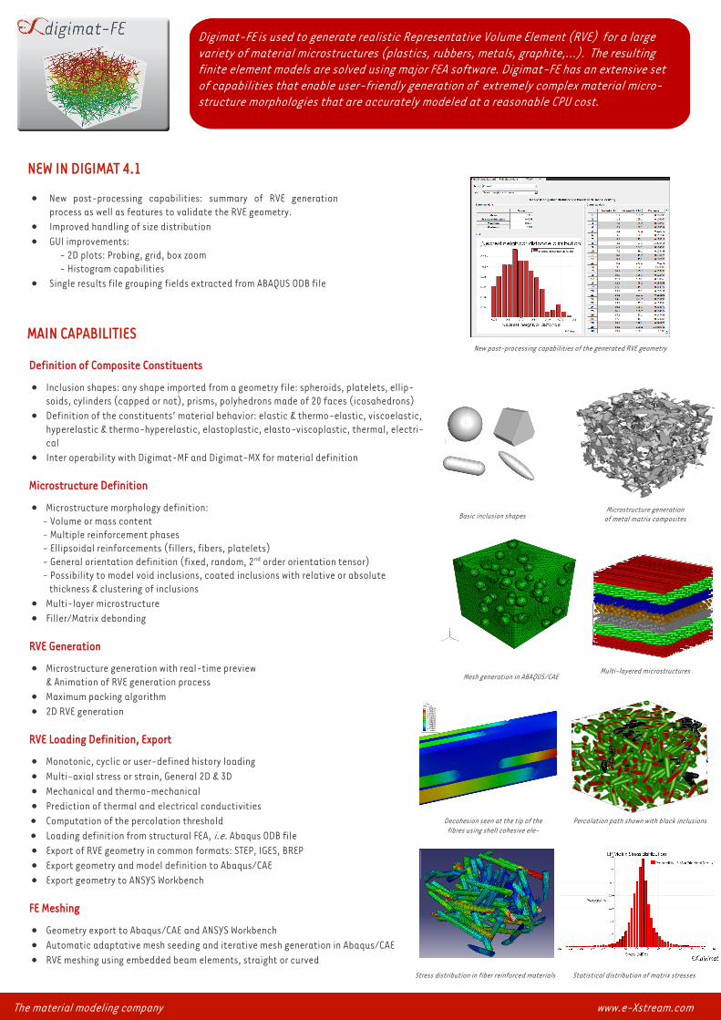
Digimat-FE is used to generate realistic Representative Volume Element (RVE) for a large
variety of material microstructures (plastics, rubbers, metals, graphite,...). The resulting
finite element models are solved using major FEA software. Digimat-FE has an extensive set
of capabilities that enable user-friendly generation of extremely complex material micro-
structure morphologies that are accurately modeled at a reasonable CPU cost.
NEW IN DIGIMAT 4.1
New post-processing capabilities: summary of RVE generation
process as well as features to validate the RVE geometry.
Improved handling of size distribution
GUI improvements:
- 2D plots: Probing, grid, box zoom
- Histogram capabilities
Single results file grouping fields extracted from ABAQUS ODB file
Decohesion seen at the tip of the
fibres using shell cohesive ele-
Percolation path shown with black inclusions
MAIN CAPABILITIES
Definition of Composite Constituents
Inclusion shapes: any shape imported from a geometry file: spheroids, platelets, ellip-
soids, cylinders (capped or not), prisms, polyhedrons made of 20 faces (icosahedrons)
Definition of the constituents’ material behavior: elastic & thermo-elastic, viscoelastic,
hyperelastic & thermo-hyperelastic, elastoplastic, elasto-viscoplastic, thermal, electri-
cal
Inter operability with Digimat-MF and Digimat-MX for material definition
Microstructure Definition
Microstructure morphology definition:
- Volume or mass content
- Multiple reinforcement phases
- Ellipsoidal reinforcements (fillers, fibers, platelets)
- General orientation definition (fixed, random, 2nd order orientation tensor)
- Possibility to model void inclusions, coated inclusions with relative or absolute
thickness & clustering of inclusions
Multi-layer microstructure
Filler/Matrix debonding
RVE Generation
Microstructure generation with real-time preview
& Animation of RVE generation process
Maximum packing algorithm
2D RVE generation
RVE Loading Definition, Export
Monotonic, cyclic or user-defined history loading
Multi-axial stress or strain, General 2D & 3D
Mechanical and thermo-mechanical
Prediction of thermal and electrical conductivities
Computation of the percolation threshold
Loading definition from structural FEA, i.e. Abaqus ODB file
Export of RVE geometry in common formats: STEP, IGES, BREP
Export geometry and model definition to Abaqus/CAE
Export geometry to ANSYS Workbench
FE Meshing
Geometry export to Abaqus/CAE and ANSYS Workbench
Automatic adaptative mesh seeding and iterative mesh generation in Abaqus/CAE
RVE meshing using embedded beam elements, straight or curved
Basic inclusion shapes
Microstructure generation
of metal matrix composites
Stress distribution in fiber reinforced materials Statistical distribution of matrix stresses
Mesh generation in ABAQUS/CAE Multi-layered microstructures
The material modeling company www.e-Xstream.com
New post-processing capabilities of the generated RVE geometry
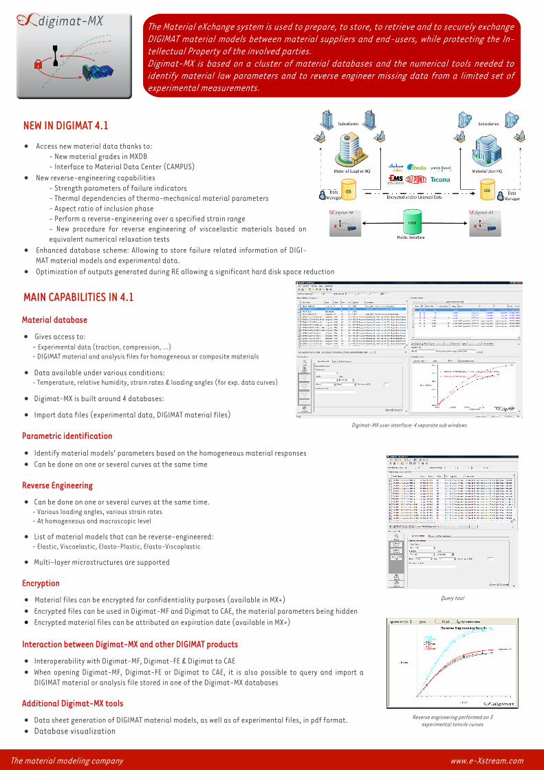
The Material eXchange system is used to prepare, to store, to retrieve and to securely exchange
DIGIMAT material models between material suppliers and end-users, while protecting the In-
tellectual Property of the involved parties.
Digimat-MX is based on a cluster of material databases and the numerical tools needed to
identify material law parameters and to reverse engineer missing data from a limited set of
experimental measurements.
MAIN CAPABILITIES IN 4.1
Material database
Gives access to:
- Experimental data (traction, compression, ...)
- DIGIMAT material and analysis files for homogeneous or composite materials
Data available under various conditions: - Temperature, relative humidity, strain rates & loading angles (for exp. data curves)
Digimat-MX is built around 4 databases:
Import data files (experimental data, DIGIMAT material files)
Parametric identification
Identify material models’ parameters based on the homogeneous material responses
Can be done on one or several curves at the same time
Reverse Engineering
Can be done on one or several curves at the same time.
- Various loading angles, various strain rates
- At homogeneous and macroscopic level
List of material models that can be reverse-engineered:
- Elastic, Viscoelastic, Elasto-Plastic, Elasto-Viscoplastic
Multi-layer microstructures are supported
Encryption
Material files can be encrypted for confidentiality purposes (available in MX+)
Encrypted files can be used in Digimat-MF and Digimat to CAE, the material parameters being hidden
Encrypted material files can be attributed an expiration date (available in MX+)
Interaction between Digimat-MX and other DIGIMAT products
Interoperability with Digimat-MF, Digimat-FE & Digimat to CAE
When opening Digimat-MF, Digimat-FE or Digimat to CAE, it is also possible to query and import a
DIGIMAT material or analysis file stored in one of the Digimat-MX databases
Additional Digimat-MX tools
Data sheet generation of DIGIMAT material models, as well as of experimental files, in pdf format.
Database visualization
Digimat-MX user interface: 4 separate sub windows
Query tool
Reverse engineering performed on 3
experimental tensile curves
The material modeling company www.e-Xstream.com
NEW IN DIGIMAT 4.1
Access new material data thanks to:
- New material grades in MXDB
- Interface to Material Data Center (CAMPUS)
New reverse-engineering capabilities
- Strength parameters of failure indicators
- Thermal dependencies of thermo-mechanical material parameters
- Aspect ratio of inclusion phase
- Perform a reverse-engineering over a specified strain range
- New procedure for reverse engineering of viscoelastic materials based on
equivalent numerical relaxation tests
Enhanced database scheme: Allowing to store failure related information of DIGI-
MAT material models and experimental data.
Optimization of outputs generated during RE allowing a significant hard disk space reduction
NEW IN DIGIMAT 4.1
User defined outputs
Interface to Hypermesh
Interface to Optistruct
DMP version of the interface to ANSYS mechanical under Windows 64 bit
DMP version of the interface to RADIOSS under Windows 64 bit
CPU speedup through improved discretization scheme of the orientation distribution function
CPU speedup through improved homogenization scheme
New tolerance for the enforcement of plane stress conditions
Viscoelastic-viscoplastic material models insensitive to time steps
Support XML file format for fiber orientation coming from Moldflow midplane
Interface to Abaqus compatible with 6.10.1 version
Improved licensing scheme for DMP computations involving distributed storage devices
New post-processing plug-in of DIGIMAT results in Abaqus/CAE
MAIN CAPABILITIES
Digimat-CAE/Injection
Takes into account:
- Orientation tensors
- Residual stresses
- Residual temperatures
- Weldlines
Digimat-CAE/Structural
FEA solver types:
- Explicit
- Implicit
Element types:
- Shell: 1st & 2nd order Triangles & Quadrangles
- 3D: Tetrahedron, Hexahedron, 1st & 2nd order, reduced and fully integrated
(For 2nd order elements, each individual integration point can be assigned an orientation
tensor by using the DIGIMAT orientation file format)
Micromechanical Material Model :
- Linear
- Nonlinear
- Rate dependent
- Finite strain
Weak coupling interfaces to all FEA solvers
for thermo-elastic material properties
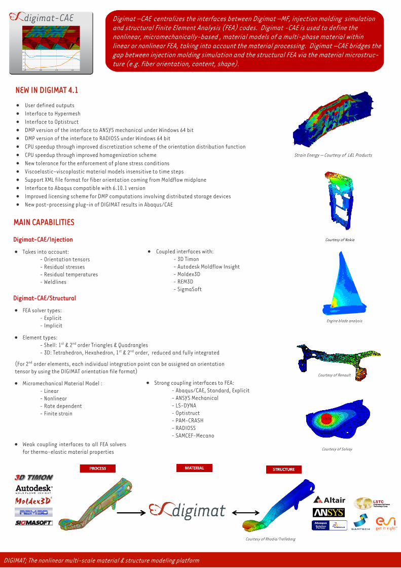
Courtesy of Solvay
Courtesy of Renault
Courtesy of Nokia
Engine blade analysis
DIGIMAT; The nonlinear multi-scale material & structure modeling platform
Digimat –CAE centralizes the interfaces between Digimat –MF, injection molding simulation
and structural Finite Element Analysis (FEA) codes. Digimat -CAE is used to define the
nonlinear, micromechanically-based , material models of a multi-phase material within
linear or nonlinear FEA, taking into account the material processing. Digimat –CAE bridges the
gap between injection molding simulation and the structural FEA via the material microstruc-
ture (e.g. fiber orientation, content, shape).
Courtesy of Rhodia/Trelleborg
Coupled interfaces with:
- 3D Timon
- Autodesk Moldflow Insight
- Moldex3D
- REM3D
- SigmaSoft
Strong coupling interfaces to FEA:
- Abaqus/CAE, Standard, Explicit
- ANSYS Mechanical
- LS-DYNA
- Optistruct
- PAM-CRASH
- RADIOSS
- SAMCEF-Mecano
Strain Energy — Courtesy of L&L Products
Supported File Format
Meshes:
- Abaqus
- ANSYS
- Ideas
- LS-DYNA
- PAM-CRASH
- Patran
- RADIOSS
- REM3D
- 3D Timon
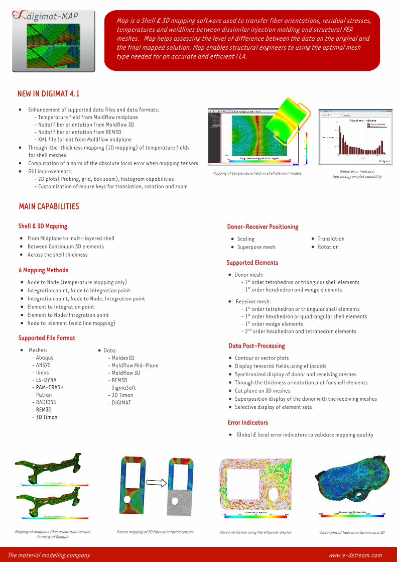
Map is a Shell & 3D mapping software used to transfer fiber orientations, residual stresses,
temperatures and weldlines between dissimilar injection molding and structural FEA
meshes. Map helps assessing the level of difference between the data on the original and
the final mapped solution. Map enables structural engineers to using the optimal mesh
type needed for an accurate and efficient FEA.
NEW IN DIGIMAT 4.1
MAIN CAPABILITIES
Enhancement of supported data files and data formats:
- Temperature field from Moldflow midplane
- Nodal fiber orientation from Moldflow 3D
- Nodal fiber orientation from REM3D
- XML file format from Moldflow midplane
Through-the-thickness mapping (1D mapping) of temperature fields
for shell meshes
Computation of a norm of the absolute local error when mapping tensors
GUI improvements:
- 2D plots( Probing, grid, box zoom), histogram capabilities
- Customization of mouse keys for translation, rotation and zoom
Fibre orientation using the ellipsoid display
Shell & 3D Mapping
From Midplane to multi-layered shell
Between Continuum 3D elements
Across the shell thickness
Error Indicators
Global & local error indicators to validate mapping quality
Data Post-Processing
Contour or vector plots
Display tensorial fields using ellipsoids
Synchronized display of donor and receiving meshes
Through the thickness orientation plot for shell elements
Cut plane on 3D meshes
Superposition display of the donor with the receiving meshes
Selective display of element sets
Donor-Receiver Positioning
Scaling
Superpose mesh
Data:
- Moldex3D
- Moldflow Mid-Plane
- Moldflow 3D
- REM3D
- SigmaSoft
- 3D Timon
- DIGIMAT
6 Mapping Methods
Node to Node (temperature mapping only)
Integration point, Node to Integration point
Integration point, Node to Node, Integration point
Element to Integration point
Element to Node/Integration point
Node to element (weld line mapping)
Supported Elements
Donor mesh:
- 1st order tetrahedron or triangular shell elements
- 1st order hexahedron and wedge elements
Receiver mesh:
- 1st order tetrahedron or triangular shell elements
- 1st order hexahedron or quadrangular shell elements
- 1st order wedge elements
- 2nd order hexahedron and tetrahedron elements
Translation
Rotation
Mapping of midplane fiber orientation tensors
Courtesy of Renault Vector plot of fiber orientations on a 3D Partial mapping of 3D fiber orientation tensors
The material modeling company www.e-Xstream.com
Global error indicator
New histogram plot capability Mapping of temperature field on shell element models.
FEA Model
Automatic mesh generation following selected mesh refinement:
- Coarse
- Average
- Fine
Loading:
- Three-point bending
- Four-point bending
- In-plane shear
(Customized positions and amplitudes for loading points and fixations)
Core Definition
Honeycomb
Foam
(Honeycomb properties are computed using micromechanical models based on the cell
geometry and the bulk material properties)
Post-processing
Integrated post-processing including 3D and through-thickness views of stresses,
strains and failure indicators
Failure Indicators
Core:
- Maximum stress (comprehensive, shear)
Skin:
- Maximum stress
- Tsai-Wu
- Tsai-Hill
- Azzi-Tsai-Hill
Automatic Report Generation (html)
Automatic Generation and Solving of the FEA Model using a Built-in FEA Solver
Skin Definition
Pile up:
- Symmetric
- Anti-symmetric
Material properties:
- Orthotropic elastic properties of the ply
- Ply orientation
Resin/Fibers:
- Isotropic elastic properties of the resin and fibers
- Fiber weight fraction, length and orientation
The equivalent, homogenous, properties of the skins are computed using micromechanics
MAIN CAPABILITIES
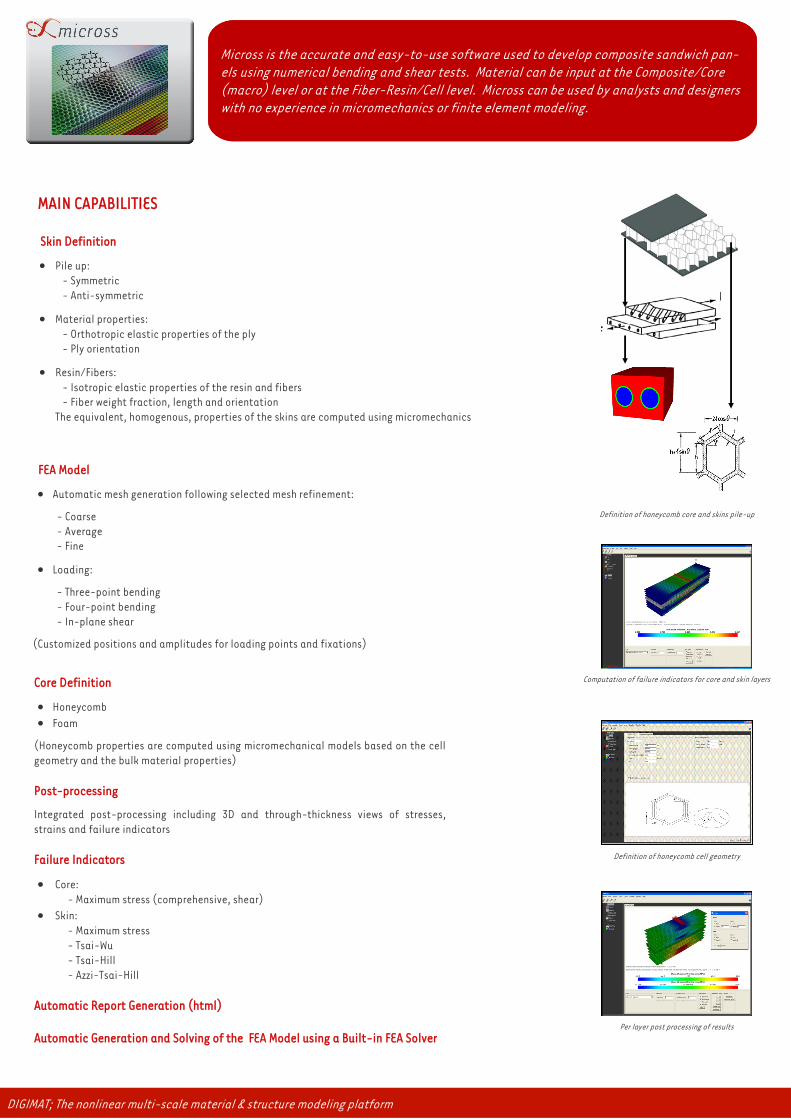
Definition of honeycomb core and skins pile-up
Computation of failure indicators for core and skin layers
Definition of honeycomb cell geometry
Per layer post processing of results
Micross is the accurate and easy-to-use software used to develop composite sandwich pan-
els using numerical bending and shear tests. Material can be input at the Composite/Core
(macro) level or at the Fiber-Resin/Cell level. Micross can be used by analysts and designers
with no experience in micromechanics or finite element modeling.
DIGIMAT; The nonlinear multi-scale material & structure modeling platform
e-Xstream engineering develops and commercializes DIGIMAT suite of software, a state of the art multi-scale material
modeling technology that speed-up the development of optimal composite materials and parts for material suppliers and
end users in the automotive, aerospace, consumer goods and industrial equipment industries. Our solutions are used by CAE
engineers, materials scientists, chemists, specialists in manufacturing processes of composite materials,... to accurately
predict the nonlinear micromechanical behavior of complex multi-phase composites materials and structures (PMC, RMC,
MMC, nanocomposites, honeycomb sandwich panels, …)
DIGIMAT, The nonlinear multi-scale material & structure modeling platform, is an efficient predictive tool that helps our
customers designing and manufacturing innovative and optimal composite materials and parts fast and cost efficiently. With
major customers in Europe, America and Asia, we have added to our deep expertise in numerical simulation the business un-
derstanding of a large variety of materials such as reinforced plastics, rubber, hard metals, nanocomposites and honeycomb
sandwich panels used across the automotive, aerospace, consumer and industrial equipments industries.
Copyright © e-Xstream engineering, 2010. e-Xstream engineering, eX, eXdigimat and
their derivatives are registered trademarks or trademarks of e-Xstream engineering SA.
All other brand, product and names or trademarks are the property of their respective owners.
Software & Consulting Services
For the optimal design of
Advanced Materials, Products & Processes
Using state-of-the-art
Multi-Scale Material Modeling Technology
Resources
VISIT
www.e-Xstream.com
INFO REQUEST
TECHNICAL SUPPORT
WORLWIDE CONTACTS
www.e-xstream.com/en/e-xstream-engineering/locations.html
WORKSHOP & EVENTS
www.e-xstream.com/en/workshops-and-events/
TECHNOLOGICAL PARTNERSHIPS
http://www.e-xstream.com/en/e-xstream-engineering/partnerships.html