Embed Size (px)
Citation preview
Renault KANGOO Z.E.Vehicle user manual

0.1
Translated from French. Copying or translation, in part or in full, is forbidden unless prior written permission has been obtained from the vehicle manu-facturer.
This driver’s handbook contains the information necessary:– for you to familiarise yourself with your vehicle, to use it to its best advantage and to benefit fully from the all the functions and
the technical developments it incorporates.– to ensure that it always gives the best performance by following the simple, but comprehensive advice concerning regular main-
tenance.– to enable you to deal quickly with minor faults not requiring specialist attention.It is well worth taking a few minutes to read this handbook to familiarise yourself with the information and guidelines it contains about the vehicle and its functions and new features. If certain points are still unclear, our Network technicians will be only too pleased to provide you with any additional information.To help you, you will find the following symbols:
and visible in the vehicle, indicate that you should consult the manual for detailed information and/or limits on opera-tions with respect to your vehicle’s equipment.
Welcome to your new electric vehicle
The descriptions of the models given in this handbook are based on the technical specifications at the time of writing. This hand-book covers all items of equipment (both standard and optional) available for these models but whether or not these are fitted to the vehicle depends on the version, options selected and the country where the vehicle is sold.This handbook may also contain information about items of equipment to be introduced later in the model year.Throughout the manual, the “approved Dealer” is your RENAULT Dealer.
anywhere in the manual indicates a hazard, danger or a safety recommendation.
Enjoy driving your new vehicle.

0.2
0.3
Getting to know your vehicle ...............................
Driving ...................................................................
Your comfort .........................................................
Maintenance .........................................................
Practical advice ....................................................
Technical specifications ......................................
Alphabetical index ...............................................
Sections
1
C O N T E N T S
2
3
4
5
6
7

0.4
1.1
Section 1: Getting to know your vehicleElectric vehicle: introduction . . . . . . . . . . . . . . . . . . . . . . . . . . . . . . . . . . . . . . . . . . . . . . . . . . . . . . . 1.2Important recommendations . . . . . . . . . . . . . . . . . . . . . . . . . . . . . . . . . . . . . . . . . . . . . . . . . . . . . . . 1.8Electric vehicle: charging . . . . . . . . . . . . . . . . . . . . . . . . . . . . . . . . . . . . . . . . . . . . . . . . . . . . . . . . . . 1.9Key, radio frequency remote control: general information, use, deadlocking . . . . . . . . . . . . . . . . . . 1.17Doors . . . . . . . . . . . . . . . . . . . . . . . . . . . . . . . . . . . . . . . . . . . . . . . . . . . . . . . . . . . . . . . . . . . . . . . . . 1.22Automatic locking when driving . . . . . . . . . . . . . . . . . . . . . . . . . . . . . . . . . . . . . . . . . . . . . . . . . . . . . 1.28Headrests/Front seats . . . . . . . . . . . . . . . . . . . . . . . . . . . . . . . . . . . . . . . . . . . . . . . . . . . . . . . . . . . . 1.29Roof flap . . . . . . . . . . . . . . . . . . . . . . . . . . . . . . . . . . . . . . . . . . . . . . . . . . . . . . . . . . . . . . . . . . . . . . 1.34Swivelling partition . . . . . . . . . . . . . . . . . . . . . . . . . . . . . . . . . . . . . . . . . . . . . . . . . . . . . . . . . . . . . . . 1.36Seat belts. . . . . . . . . . . . . . . . . . . . . . . . . . . . . . . . . . . . . . . . . . . . . . . . . . . . . . . . . . . . . . . . . . . . . . 1.37Methods of restraint in addition to the front seat belts . . . . . . . . . . . . . . . . . . . . . . . . . . . . . . . . . . . . 1.41Side protection devices . . . . . . . . . . . . . . . . . . . . . . . . . . . . . . . . . . . . . . . . . . . . . . . . . . . . . . . . . . . 1.44Additional methods of restraint . . . . . . . . . . . . . . . . . . . . . . . . . . . . . . . . . . . . . . . . . . . . . . . . . . . . . 1.45Child safety: General information . . . . . . . . . . . . . . . . . . . . . . . . . . . . . . . . . . . . . . . . . . . . . . . . . . . 1.46
Choosing a child seat mounting . . . . . . . . . . . . . . . . . . . . . . . . . . . . . . . . . . . . . . . . . . . . . . . 1.49Fitting a child seat . . . . . . . . . . . . . . . . . . . . . . . . . . . . . . . . . . . . . . . . . . . . . . . . . . . . . . . . . 1.52Deactivating/activating the front passenger airbag . . . . . . . . . . . . . . . . . . . . . . . . . . . . . . . . 1.58
Steering wheel/Power-assisted steering . . . . . . . . . . . . . . . . . . . . . . . . . . . . . . . . . . . . . . . . . . . . . . 1.61Driving position . . . . . . . . . . . . . . . . . . . . . . . . . . . . . . . . . . . . . . . . . . . . . . . . . . . . . . . . . . . . . . . . . 1.62Warning lights . . . . . . . . . . . . . . . . . . . . . . . . . . . . . . . . . . . . . . . . . . . . . . . . . . . . . . . . . . . . . . . . . . 1.66Displays and indicators . . . . . . . . . . . . . . . . . . . . . . . . . . . . . . . . . . . . . . . . . . . . . . . . . . . . . . . . . . . 1.69Trip computer . . . . . . . . . . . . . . . . . . . . . . . . . . . . . . . . . . . . . . . . . . . . . . . . . . . . . . . . . . . . . . . . . . 1.72Clock and outdoor temperature . . . . . . . . . . . . . . . . . . . . . . . . . . . . . . . . . . . . . . . . . . . . . . . . . . . . . 1.81Rear view mirrors . . . . . . . . . . . . . . . . . . . . . . . . . . . . . . . . . . . . . . . . . . . . . . . . . . . . . . . . . . . . . . . 1.82Audible and visual signals . . . . . . . . . . . . . . . . . . . . . . . . . . . . . . . . . . . . . . . . . . . . . . . . . . . . . . . . . 1.83Pedestrian horn . . . . . . . . . . . . . . . . . . . . . . . . . . . . . . . . . . . . . . . . . . . . . . . . . . . . . . . . . . . . . . . . . 1.84External lighting and signals . . . . . . . . . . . . . . . . . . . . . . . . . . . . . . . . . . . . . . . . . . . . . . . . . . . . . . . 1.85Headlight beam adjustment . . . . . . . . . . . . . . . . . . . . . . . . . . . . . . . . . . . . . . . . . . . . . . . . . . . . . . . . 1.88Washers, wipers . . . . . . . . . . . . . . . . . . . . . . . . . . . . . . . . . . . . . . . . . . . . . . . . . . . . . . . . . . . . . . . . 1.90Additional heating tank . . . . . . . . . . . . . . . . . . . . . . . . . . . . . . . . . . . . . . . . . . . . . . . . . . . . . . . . . . . 1.93
1.2
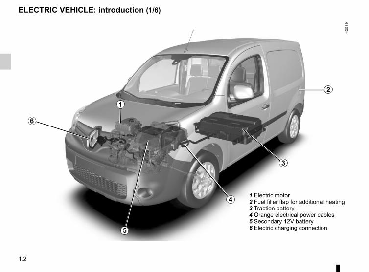
1 Electric motor2 Fuel filler flap for additional heating3 Traction battery4 Orange electrical power cables5 Secondary 12V battery6 Electric charging connection
3
4
5
1
6
ELECTRIC VEHICLE: introduction (1/6)
2
1.3
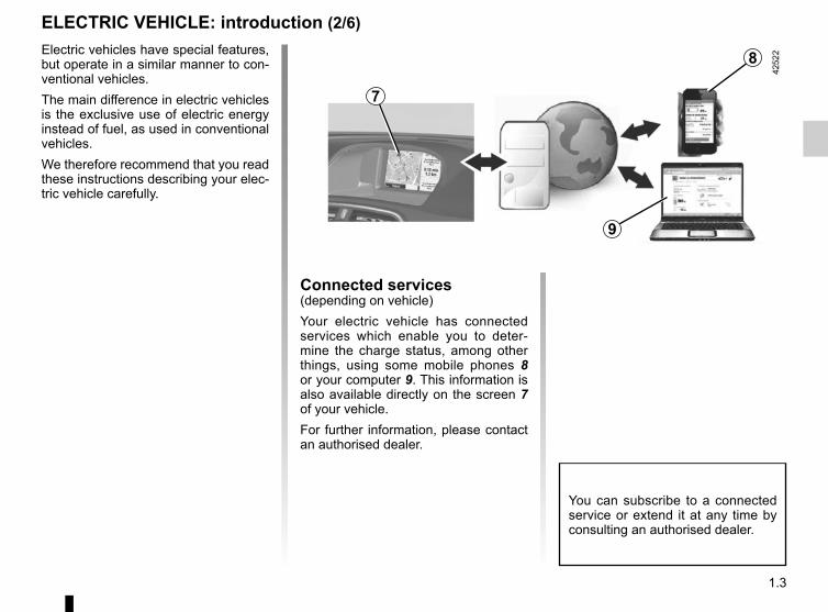
ELECTRIC VEHICLE: introduction (2/6)Electric vehicles have special features, but operate in a similar manner to con-ventional vehicles.The main difference in electric vehicles is the exclusive use of electric energy instead of fuel, as used in conventional vehicles.We therefore recommend that you read these instructions describing your elec-tric vehicle carefully.
Connected services(depending on vehicle)Your electric vehicle has connected services which enable you to deter-mine the charge status, among other things, using some mobile phones 8 or your computer 9. This information is also available directly on the screen 7 of your vehicle.For further information, please contact an authorised dealer.
You can subscribe to a connected service or extend it at any time by consulting an authorised dealer.
7
8
9
1.4
ELECTRIC VEHICLE: introduction (3/6)
BatteriesYour electric vehicle has two types of battery:– a 400V traction battery;– a standard 12V battery, identical to
the one used in conventional vehi-cles.
Traction batteryThis battery stores the energy neces-sary to operate the motor in your elec-tric vehicle properly. As with any bat-tery, it discharges after use, and must be regularly recharged.You do not have to wait until the traction battery hits the reserve level in order to recharge it.Battery charging times vary depending on the type of specific wall unit socket or public terminal you connect to.Your vehicle range will depend on the charge level of the traction battery, and also on your driving style, the outdoor temperature and the type of road.Please refer to information on “Vehicle range: recommendations” in Section 2.
12 volt batteryThe second battery on your vehicle is a 12V battery, similar to those used on conventional vehicles: this supplies the energy required to operate vehicle equipment (lights, windscreen wipers, ABS, etc).
1.5
ELECTRIC VEHICLE: introduction (4/6)
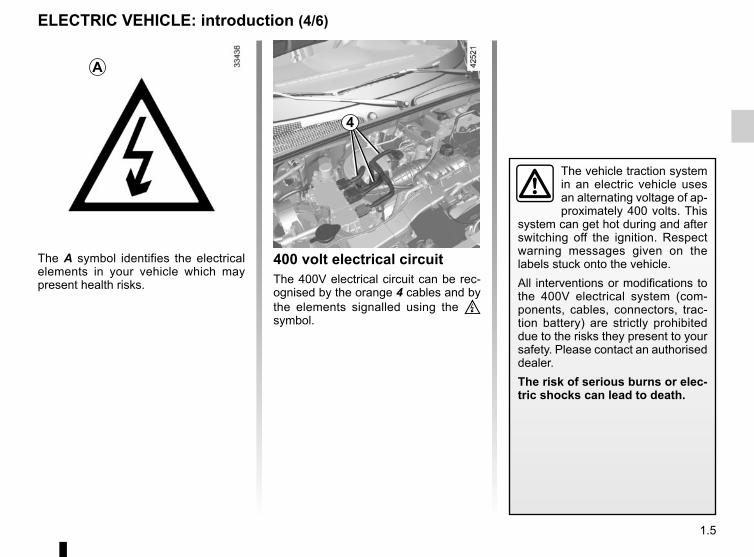
The A symbol identifies the electrical elements in your vehicle which may present health risks.
A
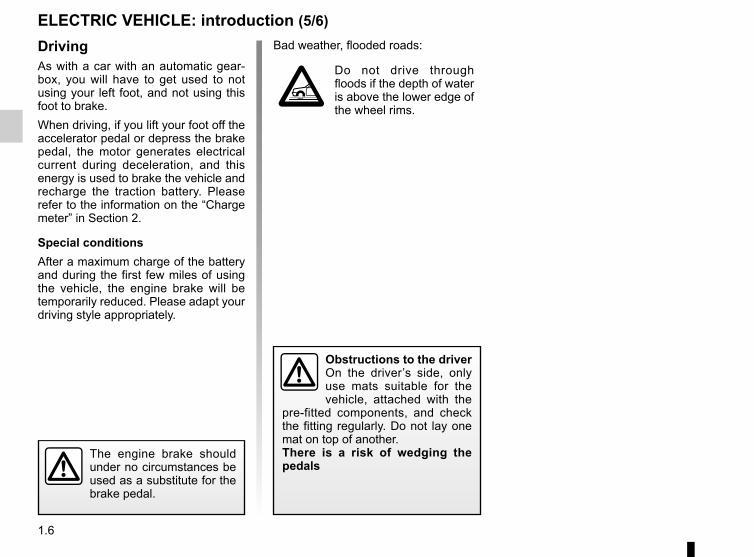
400 volt electrical circuitThe 400V electrical circuit can be rec-ognised by the orange 4 cables and by the elements signalled using the ṑ symbol.
The vehicle traction system in an electric vehicle uses an alternating voltage of ap-proximately 400 volts. This
system can get hot during and after switching off the ignition. Respect warning messages given on the labels stuck onto the vehicle.All interventions or modifications to the 400V electrical system (com-ponents, cables, connectors, trac-tion battery) are strictly prohibited due to the risks they present to your safety. Please contact an authorised dealer.The risk of serious burns or elec-tric shocks can lead to death.
4
1.6
The engine brake should under no circumstances be used as a substitute for the brake pedal.
ELECTRIC VEHICLE: introduction (5/6)
DrivingAs with a car with an automatic gear-box, you will have to get used to not using your left foot, and not using this foot to brake.When driving, if you lift your foot off the accelerator pedal or depress the brake pedal, the motor generates electrical current during deceleration, and this energy is used to brake the vehicle and recharge the traction battery. Please refer to the information on the “Charge meter” in Section 2.
Special conditionsAfter a maximum charge of the battery and during the first few miles of using the vehicle, the engine brake will be temporarily reduced. Please adapt your driving style appropriately.
Bad weather, flooded roads:
Do not drive through floods if the depth of water is above the lower edge of the wheel rims.
Obstructions to the driverOn the driver’s side, only use mats suitable for the vehicle, attached with the
pre-fitted components, and check the fitting regularly. Do not lay one mat on top of another.There is a risk of wedging the pedals
1.7
NoiseElectric vehicles are particularly quiet. You will not yet necessarily be used to it, and neither will other road users. It is difficult for them to hear the vehicle when it is moving. We would therefore recommend that you are aware of the horn and make use of it, especially when driving in a built-up area or when manoeuvring. Please refer to the information on the “Horn” in Section 1.As the motor is silent, you will hear noises that you are not used to hearing (aerodynamic noises, tyre noise, etc.)Each time the ignition is switched off, the ventilation will be switched off after about ten seconds.
Your electric vehicle is silent, so when you get out, always check that the gear selector is on P, engage the
handbrake and switch off the igni-tion.RISK OF SERIOUS INJURY
ELECTRIC VEHICLE: introduction (6/6)
1.8
IMPORTANT RECOMMENDATIONS
Please read these instructions carefully. Failure to follow these instructions may lead to a risk of fire, serious injury or electric shock which may present a risk to life.
In the event of an accident or impactIn the event of an accident or an impact to the underside of the vehicle (e.g.: striking a post, raised kerb or other street furni-ture), this may damage the electric circuit or the traction battery.Have the vehicle checked by an authorised dealer.Never touch the “400 volt” components or orange cables which are exposed and visible inside or outside the vehicle.In the event of serious damage to the traction battery, leaks may occur:– never touch the liquids (fluids, etc.) coming from the traction battery;– in the event of contact with the body, wash the affected area with plenty of water and consult a doctor as soon as possible.In the event of an impact, even slight, against the charging flap and/or valve, have them checked by an authorised dealer as soon as possible.
In the event of fireIn the event of fire, make everyone evacuate the vehicle immediately and contact the emergency services, informing them that this is an electric vehicle.Only use extinguishing agents ABC or BC that are permitted for use with electrical fires. Do not use water or other extinguish-ing agents.In the event of damage to the electrical circuit, please call an authorised dealer.
All towing operationsPlease refer to the information on “Towing, breakdowns” in Section 5.
Washing the vehicleNever wash the engine compartment, the charging connection or the traction battery with a high-pressure jet.This risks damaging the electric circuit.Never wash the vehicle while it is charging. Risk of electric shock and a risk to life.
1.9
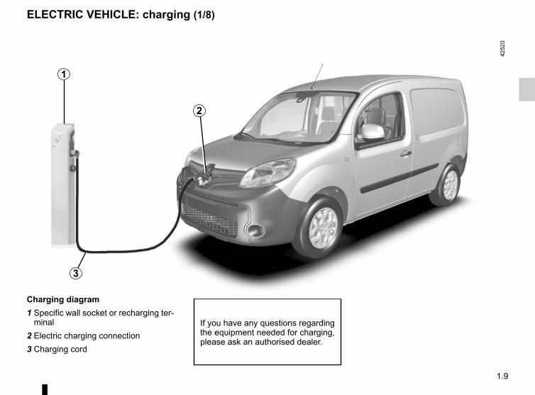
ELECTRIC VEHICLE: charging (1/8)
Charging diagram1 Specific wall socket or recharging ter-
minal2 Electric charging connection3 Charging cord
If you have any questions regarding the equipment needed for charging, please ask an authorised dealer.
1
3
2
1.10
ELECTRIC VEHICLE: charging (2/8)
Important recommendations for charging your vehiclePlease read these instructions carefully. Failure to follow these instructions may lead to a risk of fire, serious injury or electric shocks which could result in death.
ChargingDo not do anything to the vehicle during charging (washing, working in the engine compartment, etc.).In the event of the presence of water, signs of corrosion or foreign bodies in the charging cord connector or in the vehicle charg-ing socket, do not charge the vehicle. Fire hazard.Do not attempt to touch the cord contacts, the domestic socket or the vehicle charging socket, or introduce objects into them.Never plug the charging cord into an adapter, multiple socket or extension lead.The use of generators is prohibited.Do not remove or change the vehicle charging socket or the charging cord. Fire hazard.Do not modify or perform any action on the installation during charging.In the event of an impact, even slight, against the charging socket or valve, have them checked by an authorised dealer as soon as possible.Take care of the cord: do not tread on it, immerse it in water or pull on it or let anything knock against it. Check regularly that the charging cord is in good condition.Do not use in the event of any damage to the charging cord (corrosion, discolouring, cuts, etc.) or to the unit. Please see an authorised dealer for a replacement.
1.11
ELECTRIC VEHICLE: charging (3/8)
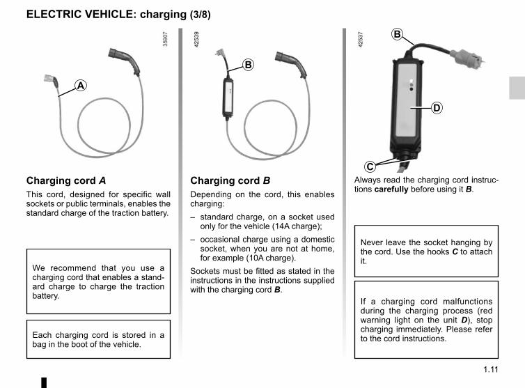
Charging cord AThis cord, designed for specific wall sockets or public terminals, enables the standard charge of the traction battery.
A
Always read the charging cord instruc-tions carefully before using it B.
B
Charging cord BDepending on the cord, this enables charging:– standard charge, on a socket used
only for the vehicle (14A charge);– occasional charge using a domestic
socket, when you are not at home, for example (10A charge).
Sockets must be fitted as stated in the instructions in the instructions supplied with the charging cord B.
C
If a charging cord malfunctions during the charging process (red warning light on the unit D), stop charging immediately. Please refer to the cord instructions.
We recommend that you use a charging cord that enables a stand-ard charge to charge the traction battery.
Each charging cord is stored in a bag in the boot of the vehicle.
Never leave the socket hanging by the cord. Use the hooks C to attach it.
B
D
1.12
ELECTRIC VEHICLE: charging (4/8)
Important recommendations for charging your vehiclePlease read these instructions carefully. Failure to follow these instructions may lead to a risk of fire, serious injury or electric shocks which could result in death.
Choice of charging cordThe standard charging cords supplied with the vehicle have been designed specifically for this vehicle. It is designed to protect you against the risks of electric shock that can lead to death or fire.For safety reasons, the use of a charging cord not recommended by the manufacturer is strictly forbidden. Failure to follow this instruction can lead to risks of fire or electric shock that can prove fatal. For information on a charging cord suited to your vehicle, please consult an authorised dealer.
InstallationFor a standard charge– Using the charging cord A Have a special wall socket installed by a qualified professional.– Using the charging cord B The socket used to charge electric vehicles (14A charge) must be fitted by a qualified professional. Read the instructions
provided with this product carefully.For occasional charging (charging cord B) With a domestic socket (10A charge) Have a professional check that each socket to which you intend to connect the charging cord complies with the standards
and regulations in force in your country. Please read the instructions that come with the charging cord carefully to learn about precautions you must take when using
the product and the technical specifications required when fitting the socket.
1.13
ELECTRIC VEHICLE: charging (5/8)
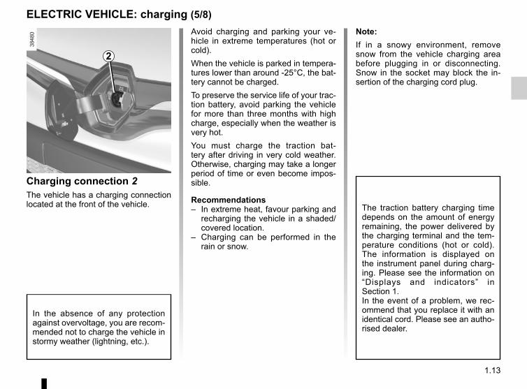
Charging connection 2The vehicle has a charging connection located at the front of the vehicle.
Avoid charging and parking your ve-hicle in extreme temperatures (hot or cold).When the vehicle is parked in tempera-tures lower than around -25°C, the bat-tery cannot be charged.To preserve the service life of your trac-tion battery, avoid parking the vehicle for more than three months with high charge, especially when the weather is very hot.You must charge the traction bat-tery after driving in very cold weather. Otherwise, charging may take a longer period of time or even become impos-sible.
Recommendations– In extreme heat, favour parking and
recharging the vehicle in a shaded/covered location.
– Charging can be performed in the rain or snow.
2
In the absence of any protection against overvoltage, you are recom-mended not to charge the vehicle in stormy weather (lightning, etc.).
Note:If in a snowy environment, remove snow from the vehicle charging area before plugging in or disconnecting. Snow in the socket may block the in-sertion of the charging cord plug.
The traction battery charging time depends on the amount of energy remaining, the power delivered by the charging terminal and the tem-perature conditions (hot or cold). The information is displayed on the instrument panel during charg-ing. Please see the information on “Displays and indicators” in Section 1.In the event of a problem, we rec-ommend that you replace it with an identical cord. Please see an autho-rised dealer.
1.14
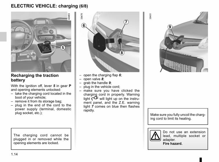
– open the charging flap 6;– open valve 8;– grab the handle 9;– plug in the vehicle cord;– make sure you have clicked the
charging cord in properly. Warning light ṋ will light up on the instru-ment panel, and the Z.E. warning light 7 comes on blue then flashes rapidly.
Recharging the traction batteryWith the ignition off, lever 5 in gear P and opening elements unlocked:– take the charging cord located in the
boot of your vehicle;– remove it from its storage bag;– plug in the end of the cord to the
power supply (terminal, domestic plug socket, etc.);
ELECTRIC VEHICLE: charging (6/8)
6
8
The charging cord cannot be plugged in or removed while the opening elements are locked.
9
Make sure you fully uncoil the charg-ing cord to limit its heating.
5
Do not use an extension lead, multiple socket or adapter.Fire hazard.
7
1.15
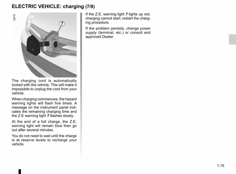
The charging cord is automatically locked with the vehicle. This will make it impossible to unplug the cord from your vehicle.When charging commences, the hazard warning lights will flash five times. A message on the instrument panel indi-cates the remaining charging time and the Z.E warning light 7 flashes slowly.At the end of a full charge, the Z.E. warning light will remain blue then go out after several minutes.You do not need to wait until the charge is at reserve levels to recharge your vehicle.
ELECTRIC VEHICLE: charging (7/8)
7
If the Z.E. warning light 7 lights up red, charging cannot start; restart the charg-ing procedure.If the problem persists, change power supply (terminal, etc.) or consult and approved Dealer.
1.16
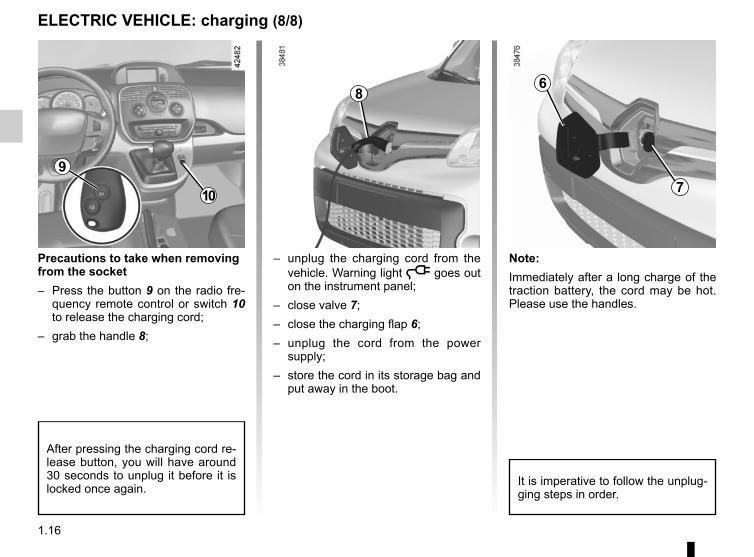
Precautions to take when removing from the socket– Press the button 9 on the radio fre-
quency remote control or switch 10 to release the charging cord;
– grab the handle 8;
– unplug the charging cord from the vehicle. Warning light ṋ goes out on the instrument panel;
– close valve 7;– close the charging flap 6;– unplug the cord from the power
supply;– store the cord in its storage bag and
put away in the boot.
ELECTRIC VEHICLE: charging (8/8)
10
6
7
After pressing the charging cord re-lease button, you will have around 30 seconds to unplug it before it is locked once again.
Note:Immediately after a long charge of the traction battery, the cord may be hot. Please use the handles.
8
It is imperative to follow the unplug-ging steps in order.
9
1.17
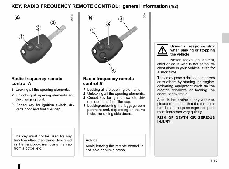
KEY, RADIO FREQUENCY REMOTE CONTROL: general information (1/2)
Radio frequency remote control A1 Locking all the opening elements.2 Unlocking all opening elements and
the charging cord.3 Coded key for ignition switch, dri-
ver’s door and fuel filler cap.
1
23
The key must not be used for any function other than those described in the handbook (removing the cap from a bottle, etc.).
AdviceAvoid leaving the remote control in hot, cold or humid areas.
Driver’s responsibility when parking or stopping the vehicleNever leave an animal,
child or adult who is not self-suffi-cient alone in your vehicle, even for a short time.They may pose a risk to themselves or to others by starting the engine, activating equipment such as the electric windows or locking the doors, for example.Also, in hot and/or sunny weather, please remember that the tempera-ture inside the passenger compart-ment increases very quickly.RISK OF DEATH OR SERIOUS INJURY.
Radio frequency remote control B1 Locking all the opening elements.2 Unlocking all the opening elements.3 Coded key for ignition switch, driv-
er’s door and fuel filler cap.4 Locking/unlocking the luggage com-
partment and, depending on the ve-hicle, the sliding side doors.
12
3
4
BA
1.18
Radio frequency remote control operating rangeThis varies according to the surroun-dings: take care not to lock or unlock the doors by inadvertently pressing the buttons on the remote control.
InterferenceInterference by factors in the imme-diate vicinity (external installations or the use of equipment operating on the same frequency as the remote control) may affect the operation of the remote control.Note: if a door is not opened within approximately 2 seconds of the door being unlocked by remote control, the doors will lock again automatically.
KEY, RADIO FREQUENCY REMOTE CONTROL: general information (2/2)
For replacement, or if you require an additional remote control.You must only contact an approved Dealer.– To replace a remote control, the
vehicle must be taken to an ap-proved Dealer as both the vehi-cle and the remote control are needed to initialise the system.
– Depending on the vehicle, you have the option of using up to four remote controls.
Remote control unit failureMake sure that the correct battery type is being used, and that the bat-tery is in good condition and inser-ted correctly. These batteries have a service life of approximately two years.To learn how to change the battery, please refer to the information on the “Key, radio frequency remote control: Batteries” in Section 5.
1.19
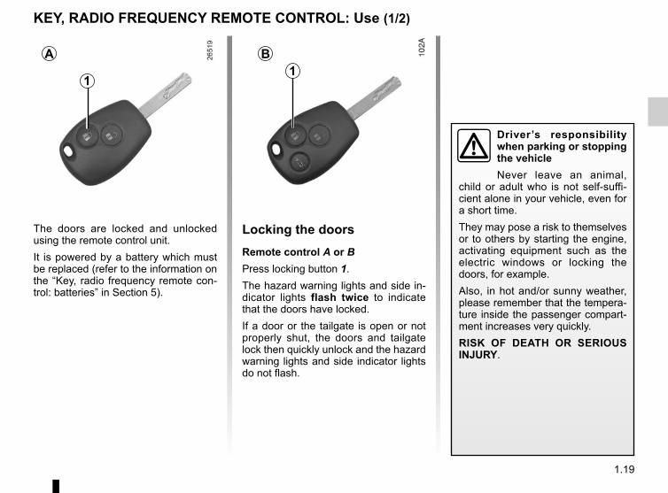
KEY, RADIO FREQUENCY REMOTE CONTROL: Use (1/2)
The doors are locked and unlocked using the remote control unit.It is powered by a battery which must be replaced (refer to the information on the “Key, radio frequency remote con-trol: batteries” in Section 5).
Locking the doorsRemote control A or BPress locking button 1.The hazard warning lights and side in-dicator lights flash twice to indicate that the doors have locked.If a door or the tailgate is open or not properly shut, the doors and tailgate lock then quickly unlock and the hazard warning lights and side indicator lights do not flash.
1
A B1
Driver’s responsibility when parking or stopping the vehicleNever leave an animal,
child or adult who is not self-suffi-cient alone in your vehicle, even for a short time.They may pose a risk to themselves or to others by starting the engine, activating equipment such as the electric windows or locking the doors, for example.Also, in hot and/or sunny weather, please remember that the tempera-ture inside the passenger compart-ment increases very quickly.RISK OF DEATH OR SERIOUS INJURY.
1.20
2
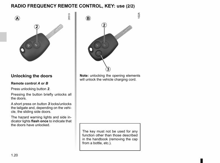
Unlocking the doorsRemote control A or BPress unlocking button 2.Pressing the button briefly unlocks all the doors.A short press on button 3 locks/unlocks the tailgate and, depending on the vehi-cle, the sliding side doors.The hazard warning lights and side in-dicator lights flash once to indicate that the doors have unlocked.
A B2
3
RADIO FREQUENCY REMOTE CONTROL, KEY: use (2/2)
The key must not be used for any function other than those described in the handbook (removing the cap from a bottle, etc.).
Note: unlocking the opening elements will unlock the vehicle charging cord.
1.21
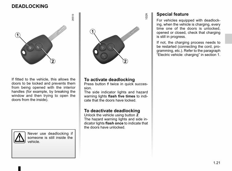
DEADLOCKING
Never use deadlocking if someone is still inside the vehicle.
1
If fitted to the vehicle, this allows the doors to be locked and prevents them from being opened with the interior handles (for example, by breaking the window and then trying to open the doors from the inside).
2
To activate deadlockingPress button 1 twice in quick succes-sion.The side indicator lights and hazard warning lights flash five times to indi-cate that the doors have locked.
To deactivate deadlockingUnlock the vehicle using button 2.The hazard warning lights and side in-dicator lights flash once to indicate that the doors have unlocked.
1
2
Special featureFor vehicles equipped with deadlock-ing, when the vehicle is charging, every time one of the doors is unlocked, opened or closed, check that charging is still in progress.If not, the charging process needs to be restarted (connecting the cord, pro-gramming, etc.). Refer to the paragraph “Electric vehicle: charging” in section 1.
1.22
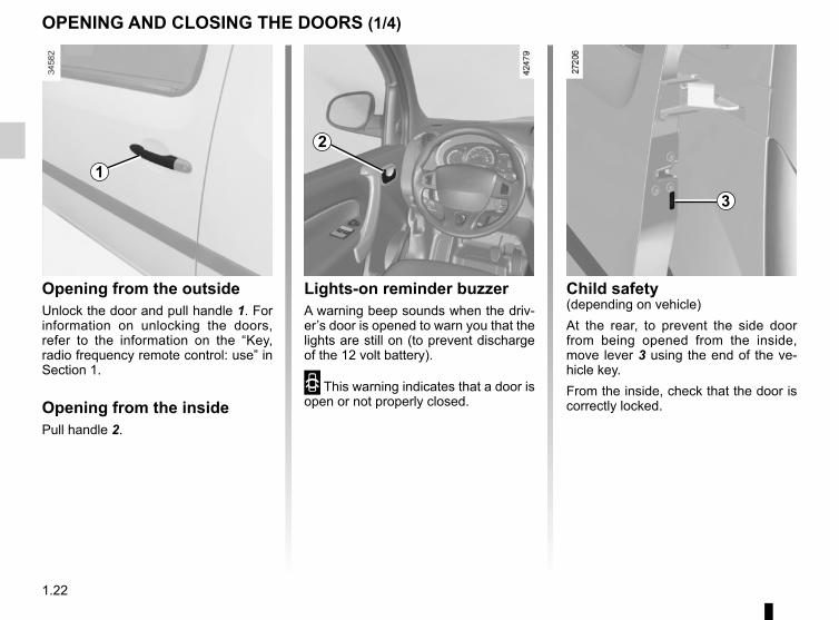
Opening from the outsideUnlock the door and pull handle 1. For information on unlocking the doors, refer to the information on the “Key, radio frequency remote control: use” in Section 1.
Opening from the insidePull handle 2.
OPENING AND CLOSING THE DOORS (1/4)
1
2
Child safety(depending on vehicle)At the rear, to prevent the side door from being opened from the inside, move lever 3 using the end of the ve-hicle key.From the inside, check that the door is correctly locked.
3
Lights-on reminder buzzerA warning beep sounds when the driv-er’s door is opened to warn you that the lights are still on (to prevent discharge of the 12 volt battery).
2 This warning indicates that a door is open or not properly closed.
1.23
OPENING AND CLOSING THE DOORS (2/4)
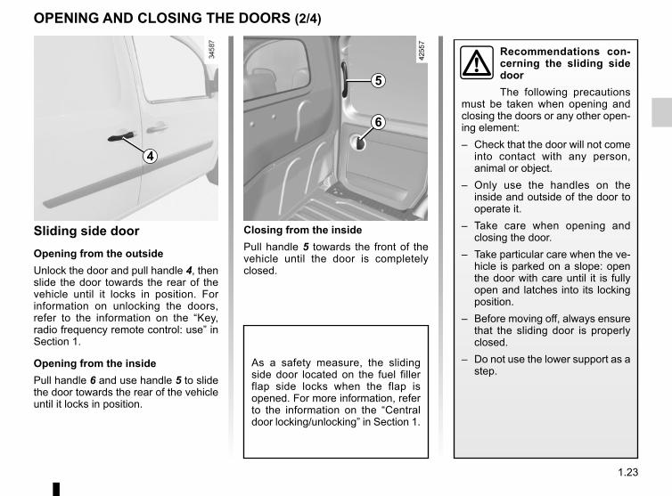
Closing from the insidePull handle 5 towards the front of the vehicle until the door is completely closed.
Sliding side doorOpening from the outsideUnlock the door and pull handle 4, then slide the door towards the rear of the vehicle until it locks in position. For information on unlocking the doors, refer to the information on the “Key, radio frequency remote control: use” in Section 1.
Opening from the insidePull handle 6 and use handle 5 to slide the door towards the rear of the vehicle until it locks in position.
Recommendations con-cerning the sliding side doorThe following precautions
must be taken when opening and closing the doors or any other open-ing element:– Check that the door will not come
into contact with any person, animal or object.
– Only use the handles on the inside and outside of the door to operate it.
– Take care when opening and closing the door.
– Take particular care when the ve-hicle is parked on a slope: open the door with care until it is fully open and latches into its locking position.
– Before moving off, always ensure that the sliding door is properly closed.
– Do not use the lower support as a step.
4
5
6
As a safety measure, the sliding side door located on the fuel filler flap side locks when the flap is opened. For more information, refer to the information on the “Central door locking/unlocking” in Section 1.
1.24
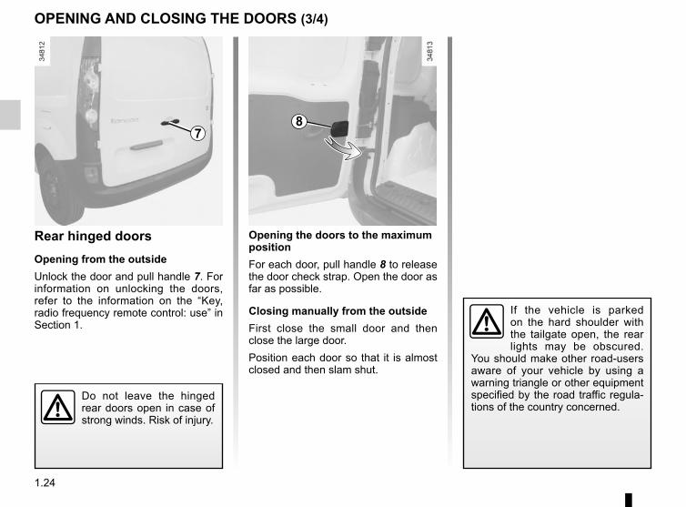
Opening the doors to the maximum positionFor each door, pull handle 8 to release the door check strap. Open the door as far as possible.
Closing manually from the outsideFirst close the small door and then close the large door.Position each door so that it is almost closed and then slam shut.
Rear hinged doorsOpening from the outsideUnlock the door and pull handle 7. For information on unlocking the doors, refer to the information on the “Key, radio frequency remote control: use” in Section 1.
OPENING AND CLOSING THE DOORS (3/4)
If the vehicle is parked on the hard shoulder with the tailgate open, the rear lights may be obscured.
You should make other road-users aware of your vehicle by using a warning triangle or other equipment specified by the road traffic regula-tions of the country concerned.
Do not leave the hinged rear doors open in case of strong winds. Risk of injury.
78
1.25
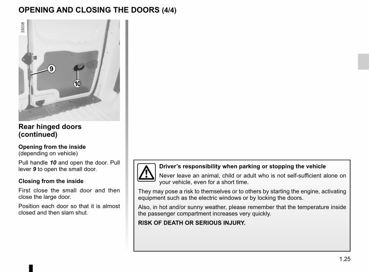
Rear hinged doors (continued)Opening from the inside(depending on vehicle)Pull handle 10 and open the door. Pull lever 9 to open the small door.
Closing from the insideFirst close the small door and then close the large door.Position each door so that it is almost closed and then slam shut.
OPENING AND CLOSING THE DOORS (4/4)
10
9
Driver’s responsibility when parking or stopping the vehicleNever leave an animal, child or adult who is not self-sufficient alone on your vehicle, even for a short time.
They may pose a risk to themselves or to others by starting the engine, activating equipment such as the electric windows or by locking the doors.Also, in hot and/or sunny weather, please remember that the temperature inside the passenger compartment increases very quickly.RISK OF DEATH OR SERIOUS INJURY.
1.26
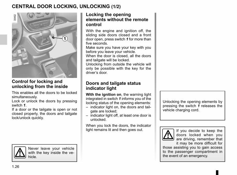
Locking the opening elements without the remote controlWith the engine and ignition off, the sliding side doors closed and a front door open, press switch 1 for more than five seconds.Make sure you have your key with you before you leave your vehicle.When the door is closed, all the doors and tailgate will be locked.Unlocking from outside the vehicle will only be possible with the key for the driver’s door.
Doors and tailgate status indicator lightWith the ignition on, the warning light integrated in switch 1 informs you of the locking status of the opening elements:– indicator light on, the doors and tail-
gate are locked;– indicator light off, at least one door is
unlocked.When you lock the doors, the indicator light remains lit and then goes out.
Control for locking and unlocking from the insideThis enables all the doors to be locked simultaneously.Lock or unlock the doors by pressing switch 1.If a door or the tailgate is open or not closed properly, the doors and tailgate lock/unlock quickly.
CENTRAL DOOR LOCKING, UNLOCKING (1/2)
Never leave your vehicle with the key inside the ve-hicle.
If you decide to keep the doors locked when you are driving, remember that it may be more difficult for
those assisting you to gain access to the passenger compartment in the event of an emergency.
1
Unlocking the opening elements by pressing the switch 1 releases the vehicle charging cord.
1.27
CENTRAL DOOR LOCKING, UNLOCKING (2/2)
2
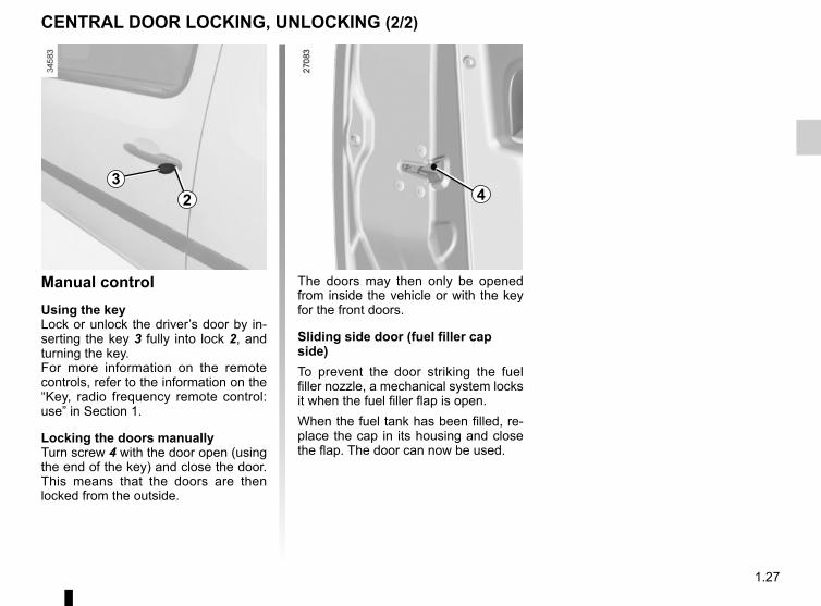
Manual controlUsing the keyLock or unlock the driver’s door by in-serting the key 3 fully into lock 2, and turning the key.For more information on the remote controls, refer to the information on the “Key, radio frequency remote control: use” in Section 1.
Locking the doors manuallyTurn screw 4 with the door open (using the end of the key) and close the door. This means that the doors are then locked from the outside.
The doors may then only be opened from inside the vehicle or with the key for the front doors.
Sliding side door (fuel filler cap side)To prevent the door striking the fuel filler nozzle, a mechanical system locks it when the fuel filler flap is open.When the fuel tank has been filled, re-place the cap in its housing and close the flap. The door can now be used.
43
1.28
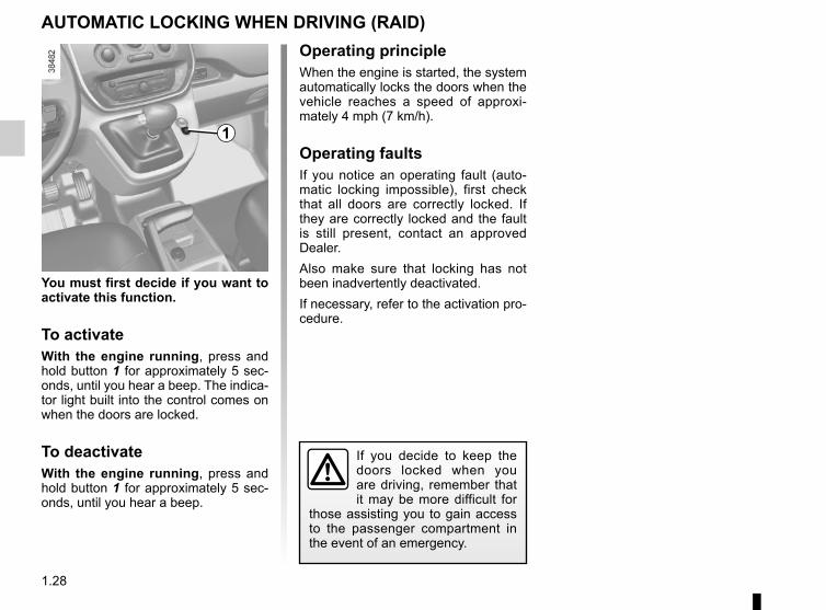
You must first decide if you want to activate this function.
To activateWith the engine running, press and hold button 1 for approximately 5 sec-onds, until you hear a beep. The indica-tor light built into the control comes on when the doors are locked.
To deactivateWith the engine running, press and hold button 1 for approximately 5 sec-onds, until you hear a beep.
If you decide to keep the doors locked when you are driving, remember that it may be more difficult for
those assisting you to gain access to the passenger compartment in the event of an emergency.
AUTOMATIC LOCKING WHEN DRIVING (RAID)Operating principleWhen the engine is started, the system automatically locks the doors when the vehicle reaches a speed of approxi-mately 4 mph (7 km/h).
Operating faultsIf you notice an operating fault (auto-matic locking impossible), first check that all doors are correctly locked. If they are correctly locked and the fault is still present, contact an approved Dealer.Also make sure that locking has not been inadvertently deactivated.If necessary, refer to the activation pro-cedure.
1
1.29
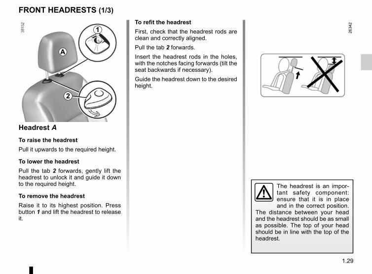
FRONT HEADRESTS (1/3)To refit the headrestFirst, check that the headrest rods are clean and correctly aligned.Pull the tab 2 forwards.Insert the headrest rods in the holes, with the notches facing forwards (tilt the seat backwards if necessary).Guide the headrest down to the desired height.
Headrest ATo raise the headrestPull it upwards to the required height.
To lower the headrestPull the tab 2 forwards, gently lift the headrest to unlock it and guide it down to the required height.
To remove the headrestRaise it to its highest position. Press button 1 and lift the headrest to release it.
A
The headrest is an impor-tant safety component: ensure that it is in place and in the correct position.
The distance between your head and the headrest should be as small as possible. The top of your head should be in line with the top of the headrest.
1
2
1.30
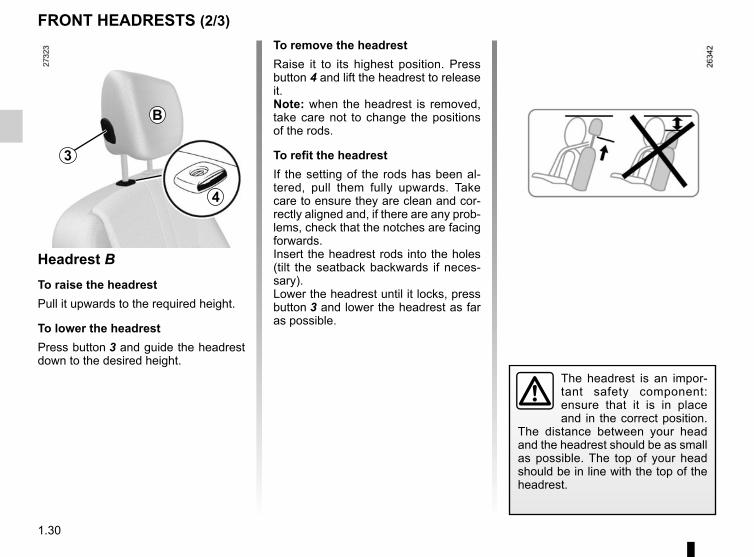
To remove the headrestRaise it to its highest position. Press button 4 and lift the headrest to release it.Note: when the headrest is removed, take care not to change the positions of the rods.
To refit the headrestIf the setting of the rods has been al-tered, pull them fully upwards. Take care to ensure they are clean and cor-rectly aligned and, if there are any prob-lems, check that the notches are facing forwards.Insert the headrest rods into the holes (tilt the seatback backwards if neces-sary).Lower the headrest until it locks, press button 3 and lower the headrest as far as possible.
FRONT HEADRESTS (2/3)
Headrest BTo raise the headrestPull it upwards to the required height.
To lower the headrestPress button 3 and guide the headrest down to the desired height.
The headrest is an impor-tant safety component: ensure that it is in place and in the correct position.
The distance between your head and the headrest should be as small as possible. The top of your head should be in line with the top of the headrest.
3
B
4
1.31
FRONT HEADRESTS (3/3)
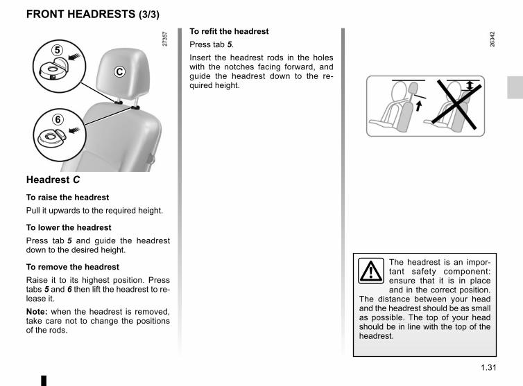
Headrest CTo raise the headrestPull it upwards to the required height.
To lower the headrestPress tab 5 and guide the headrest down to the desired height.
To remove the headrestRaise it to its highest position. Press tabs 5 and 6 then lift the headrest to re-lease it.Note: when the headrest is removed, take care not to change the positions of the rods.
To refit the headrestPress tab 5.Insert the headrest rods in the holes with the notches facing forward, and guide the headrest down to the re-quired height.
The headrest is an impor-tant safety component: ensure that it is in place and in the correct position.
The distance between your head and the headrest should be as small as possible. The top of your head should be in line with the top of the headrest.
5
6
C
1.32
FRONT SEATS (1/2)
1
2
53 4
2
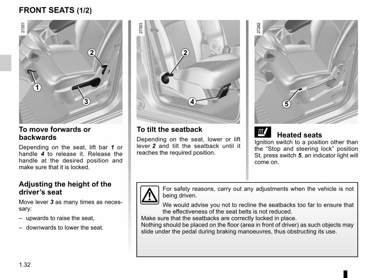
ð Heated seats Ignition switch to a position other than the “Stop and steering lock” position St, press switch 5, an indicator light will come on.
To tilt the seatbackDepending on the seat, lower or lift lever 2 and tilt the seatback until it reaches the required position.
To move forwards or backwardsDepending on the seat, lift bar 1 or handle 4 to release it. Release the handle at the desired position and make sure that it is locked.
Adjusting the height of the driver’s seatMove lever 3 as many times as neces-sary:– upwards to raise the seat,– downwards to lower the seat.
For safety reasons, carry out any adjustments when the vehicle is not being driven.We would advise you not to recline the seatbacks too far to ensure that the effectiveness of the seat belts is not reduced.
Make sure that the seatbacks are correctly locked in place.Nothing should be placed on the floor (area in front of driver) as such objects may slide under the pedal during braking manoeuvres, thus obstructing its use.
1.33
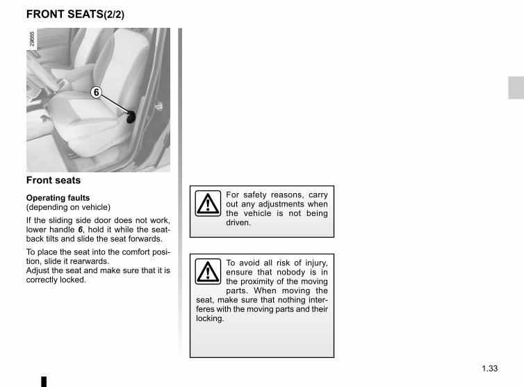
FRONT SEATS(2/2)
Front seatsOperating faults(depending on vehicle)If the sliding side door does not work, lower handle 6, hold it while the seat-back tilts and slide the seat forwards.To place the seat into the comfort posi-tion, slide it rearwards.Adjust the seat and make sure that it is correctly locked.
To avoid all risk of injury, ensure that nobody is in the proximity of the moving parts. When moving the
seat, make sure that nothing inter-feres with the moving parts and their locking.
For safety reasons, carry out any adjustments when the vehicle is not being driven.
6
1.34
ROOF FLAP (1/2)
1 2 3
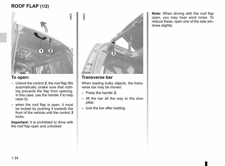
Transverse barWhen loading bulky objects, the trans-verse bar may be moved:– Press the handle 3;– lift the bar all the way to the door
pillar;– lock the bar after loading.
To open:– Unlock the control 2, the roof flap lifts
automatically (make sure that noth-ing prevents the flap from opening. In this case, use the handle 1 to help raise it);
– when the roof flap is open, it must be locked by pushing it towards the front of the vehicle until the control 2 locks.
Important: It is prohibited to drive with the roof flap open and unlocked.
Note: When driving with the roof flap open, you may hear wind noise. To reduce these, open one of the side win-dows slightly.
1.35
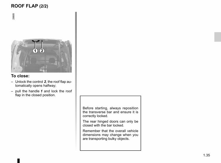
ROOF FLAP (2/2)
Before starting, always reposition the transverse bar and ensure it is correctly locked.The rear hinged doors can only be closed with the bar locked.Remember that the overall vehicle dimensions may change when you are transporting bulky objects.
1 2
To close:– Unlock the control 2, the roof flap au-
tomatically opens halfway;– pull the handle 1 and lock the roof
flap in the closed position.
1.36
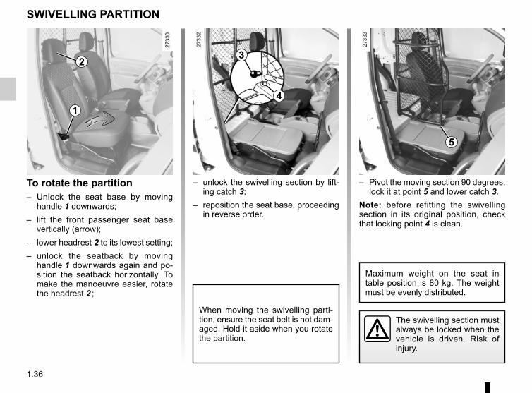
To rotate the partition– Unlock the seat base by moving
handle 1 downwards;– lift the front passenger seat base
vertically (arrow);– lower headrest 2 to its lowest setting;– unlock the seatback by moving
handle 1 downwards again and po-sition the seatback horizontally. To make the manoeuvre easier, rotate the headrest 2 ;
– Pivot the moving section 90 degrees, lock it at point 5 and lower catch 3.
Note: before refitting the swivelling section in its original position, check that locking point 4 is clean.
– unlock the swivelling section by lift-ing catch 3;
– reposition the seat base, proceeding in reverse order.
The swivelling section must always be locked when the vehicle is driven. Risk of injury.
SWIVELLING PARTITION
When moving the swivelling parti-tion, ensure the seat belt is not dam-aged. Hold it aside when you rotate the partition.
1
2 3
4
5
Maximum weight on the seat in table position is 80 kg. The weight must be evenly distributed.
1.37
SEAT BELTS (1/4)
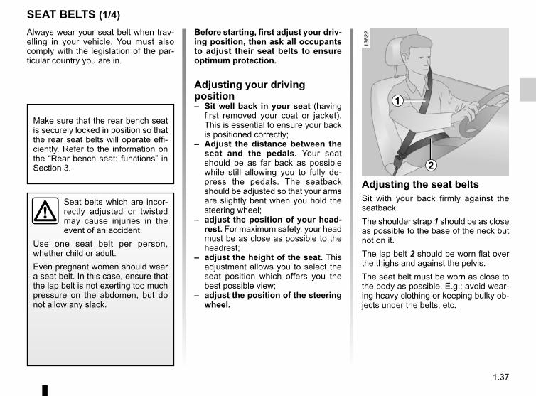
Adjusting the seat beltsSit with your back firmly against the seatback.The shoulder strap 1 should be as close as possible to the base of the neck but not on it.The lap belt 2 should be worn flat over the thighs and against the pelvis.The seat belt must be worn as close to the body as possible. E.g.: avoid wear-ing heavy clothing or keeping bulky ob-jects under the belts, etc.
1
2
Always wear your seat belt when trav-elling in your vehicle. You must also comply with the legislation of the par-ticular country you are in.
Seat belts which are incor-rectly adjusted or twisted may cause injuries in the event of an accident.
Use one seat belt per person, whether child or adult.Even pregnant women should wear a seat belt. In this case, ensure that the lap belt is not exerting too much pressure on the abdomen, but do not allow any slack.
Before starting, first adjust your driv-ing position, then ask all occupants to adjust their seat belts to ensure optimum protection.
Adjusting your driving position– Sit well back in your seat (having
first removed your coat or jacket). This is essential to ensure your back is positioned correctly;
– Adjust the distance between the seat and the pedals. Your seat should be as far back as possible while still allowing you to fully de-press the pedals. The seatback should be adjusted so that your arms are slightly bent when you hold the steering wheel;
– adjust the position of your head-rest. For maximum safety, your head must be as close as possible to the headrest;
– adjust the height of the seat. This adjustment allows you to select the seat position which offers you the best possible view;
– adjust the position of the steering wheel.
Make sure that the rear bench seat is securely locked in position so that the rear seat belts will operate effi-ciently. Refer to the information on the “Rear bench seat: functions” in Section 3.
1.38
SEAT BELTS (2/4)
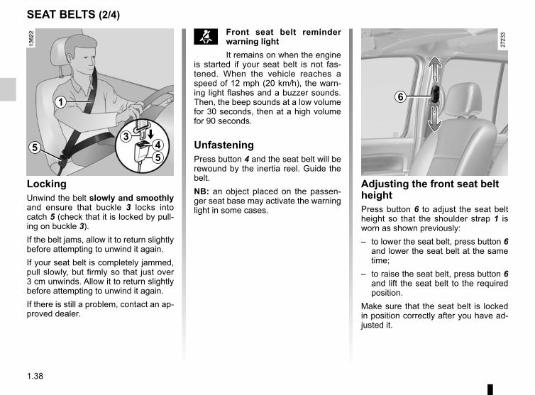
™ Front seat belt reminder warning lightIt remains on when the engine
is started if your seat belt is not fas-tened. When the vehicle reaches a speed of 12 mph (20 km/h), the warn-ing light flashes and a buzzer sounds. Then, the beep sounds at a low volume for 30 seconds, then at a high volume for 90 seconds.
UnfasteningPress button 4 and the seat belt will be rewound by the inertia reel. Guide the belt.NB: an object placed on the passen-ger seat base may activate the warning light in some cases.
6
Adjusting the front seat belt heightPress button 6 to adjust the seat belt height so that the shoulder strap 1 is worn as shown previously:– to lower the seat belt, press button 6
and lower the seat belt at the same time;
– to raise the seat belt, press button 6 and lift the seat belt to the required position.
Make sure that the seat belt is locked in position correctly after you have ad-justed it.
LockingUnwind the belt slowly and smoothly and ensure that buckle 3 locks into catch 5 (check that it is locked by pull-ing on buckle 3).If the belt jams, allow it to return slightly before attempting to unwind it again.If your seat belt is completely jammed, pull slowly, but firmly so that just over 3 cm unwinds. Allow it to return slightly before attempting to unwind it again.If there is still a problem, contact an ap-proved dealer.
1
53
45
1.39
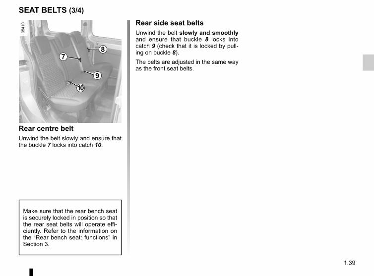
Rear centre beltUnwind the belt slowly and ensure that the buckle 7 locks into catch 10.
Rear side seat beltsUnwind the belt slowly and smoothly and ensure that buckle 8 locks into catch 9 (check that it is locked by pull-ing on buckle 8).The belts are adjusted in the same way as the front seat belts.
SEAT BELTS (3/4)
Make sure that the rear bench seat is securely locked in position so that the rear seat belts will operate effi-ciently. Refer to the information on the “Rear bench seat: functions” in Section 3.
78
9
10
1.40
SEAT BELTS (4/4)The following information applies to the vehicle’s front and rear seat belts.
– No modification may be made to the component parts of the originally fitted restraint system: belts, seats and their mountings. For special operations (e.g. fitting child seats), contact an authorised dealer.
– Do not use devices which allow any slack in the belts (e.g. clothes pegs, clips, etc.): a seat belt which is worn too loosely may cause injury in the event of an accident.
– Never wear the shoulder strap under your arm or behind your back.– Never use the same belt for more than one person and never hold a baby or child on your lap with your seat belt around
them.– The belt should never be twisted.– Following an accident, have the seat belts checked and replaced if necessary. Always replace your seat belts as soon as
they show any signs of wear.– Make sure that the buckle is inserted into the appropriate catch.– When the rear bench seat is being put back, make sure that the seat belts and buckles are correctly positioned so that they
can be used properly.– Ensure that no objects are placed in the area around the seat belt catch as they could prevent it from being properly se-
cured.– Make sure the seat belt catch is properly positioned (it should not be hidden away, crushed or flattened by people or ob-
jects).
1.41
METHODS OF RESTRAINT IN ADDITION TO THE FRONT SEAT BELTS (1/3)
1 2
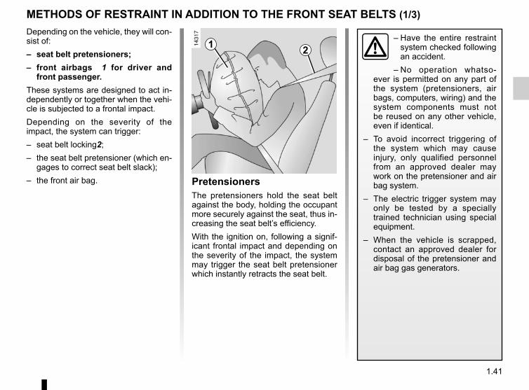
Depending on the vehicle, they will con-sist of:– seat belt pretensioners;– front airbags 1 for driver and
front passenger.These systems are designed to act in-dependently or together when the vehi-cle is subjected to a frontal impact.Depending on the severity of the impact, the system can trigger:– seat belt locking2;– the seat belt pretensioner (which en-
gages to correct seat belt slack);– the front air bag. Pretensioners
The pretensioners hold the seat belt against the body, holding the occupant more securely against the seat, thus in-creasing the seat belt’s efficiency.With the ignition on, following a signif-icant frontal impact and depending on the severity of the impact, the system may trigger the seat belt pretensioner which instantly retracts the seat belt.
– Have the entire restraint system checked following an accident.
– No operation whatso-ever is permitted on any part of the system (pretensioners, air bags, computers, wiring) and the system components must not be reused on any other vehicle, even if identical.
– To avoid incorrect triggering of the system which may cause injury, only qualified personnel from an approved dealer may work on the pretensioner and air bag system.
– The electric trigger system may only be tested by a specially trained technician using special equipment.
– When the vehicle is scrapped, contact an approved dealer for disposal of the pretensioner and air bag gas generators.
1.42
METHODS OF RESTRAINT IN ADDITION TO THE FRONT SEAT BELTS (2/3)
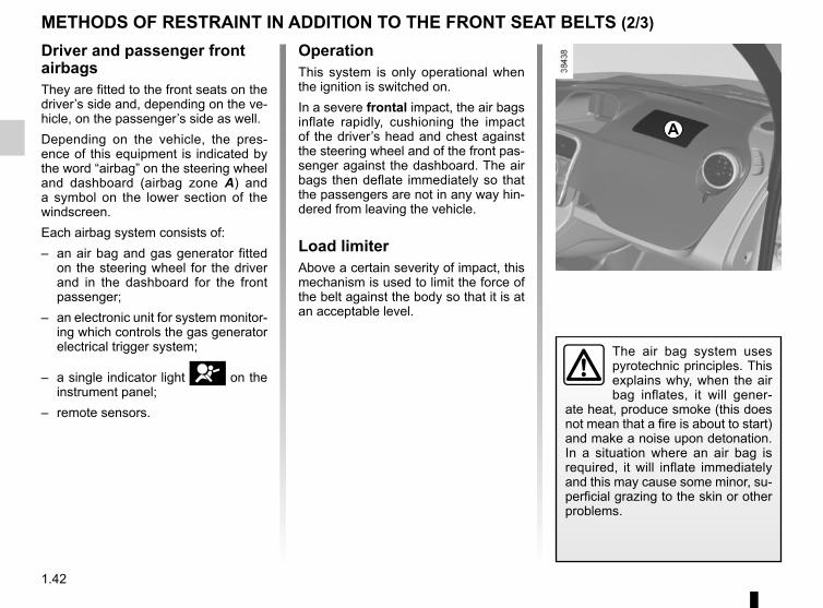
Driver and passenger front airbagsThey are fitted to the front seats on the driver’s side and, depending on the ve-hicle, on the passenger’s side as well.Depending on the vehicle, the pres-ence of this equipment is indicated by the word “airbag” on the steering wheel and dashboard (airbag zone A) and a symbol on the lower section of the windscreen.Each airbag system consists of:– an air bag and gas generator fitted
on the steering wheel for the driver and in the dashboard for the front passenger;
– an electronic unit for system monitor-ing which controls the gas generator electrical trigger system;
– a single indicator light å on the instrument panel;
– remote sensors.
A
OperationThis system is only operational when the ignition is switched on.In a severe frontal impact, the air bags inflate rapidly, cushioning the impact of the driver’s head and chest against the steering wheel and of the front pas-senger against the dashboard. The air bags then deflate immediately so that the passengers are not in any way hin-dered from leaving the vehicle.
Load limiterAbove a certain severity of impact, this mechanism is used to limit the force of the belt against the body so that it is at an acceptable level.
The air bag system uses pyrotechnic principles. This explains why, when the air bag inflates, it will gener-
ate heat, produce smoke (this does not mean that a fire is about to start) and make a noise upon detonation. In a situation where an air bag is required, it will inflate immediately and this may cause some minor, su-perficial grazing to the skin or other problems.
1.43
METHODS OF RESTRAINT IN ADDITION TO THE FRONT SEAT BELTS (3/3)
Warnings concerning the driver’s air bag– Do not modify the steering wheel or the steering wheel boss.– Do not cover the steering wheel boss under any circumstances.
– Do not attach any objects (badge, logo, clock, telephone support, etc.) to the steering wheel boss.– The steering wheel must not be removed (except by qualified personnel from our Network).– Do not sit too close to the steering wheel when driving: sit with your arms slightly bent (see Section 1 “Adjusting your driving
position”). This will allow sufficient space for the airbag to deploy correctly and be fully effective.
Warnings concerning the passenger air bag– Do not attach or glue any objects (badge, logo, clock, telephone cradle, etc.) to the dashboard in the airbag zone.– Do not place anything between the dashboard and the passenger (animal, umbrella, walking stick, parcels, etc.).– The passenger must not put his or her feet on the dashboard or seat as there is a risk that serious injuries may be sustained.
As a general rule, keep all body parts (knees, hands, head, etc.) away from the dashboard.– The devices in addition to the front passenger seat belt should be reactivated as soon as a child seat is removed, to ensure
the protection of the passenger in the event of an impact.A REAR-FACING CHILD SEAT MUST NOT BE FITTED TO THE FRONT PASSENGER SEAT UNLESS
THE ADDITIONAL RESTRAINT SYSTEMS, I.E. THE PASSENGER AIR BAG, ARE DEACTIVATED.(Refer to the information on “Child safety: front passenger airbag deactivation/activation” Section 1).
All of the warnings below are given so that the air bag is not obstructed in any way when it is inflated and also to prevent the risk of serious injuries caused by items which may be dislodged when the air bag inflates.
1.44
Side air bags(depending on vehicle)This air bag may be fitted to each of the front seats and is activated at the sides of the seats (door side) to protect the occupants in the event of a severe side impact.
Curtain air bags (depending on vehicle)These airbags may be fitted along the top of each side of the vehicle and are triggered along the front and rear side door windows to protect the pas-sengers in the event of a severe side impact.
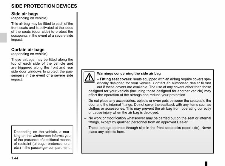
Warnings concerning the side air bag– Fitting seat covers: seats equipped with an airbag require covers spe-cifically designed for your vehicle. Contact an authorised dealer to find out if these covers are available. The use of any covers other than those
designed for your vehicle (including those designed for another vehicle) may affect the operation of the airbags and reduce your protection.
– Do not place any accessories, objects or even pets between the seatback, the door and the internal fittings. Do not cover the seatback with any items such as clothes or accessories. This may prevent the air bag from operating correctly or cause injury when the air bag is deployed.
– No work or modification whatsoever may be carried out on the seat or internal fittings, except by qualified personnel from an approved Dealer.
– These airbags operate through slits in the front seatbacks (door side): Never place any objects here.Depending on the vehicle, a mar-
king on the windscreen informs you of the presence of additional means of restraint (airbags, pretensioners, etc.) in the passenger compartment.
SIDE PROTECTION DEVICES
1.45
The air bag is designed to complement the action of the seat belt. Both the air bags and seat belts are integral parts of the same protection system. It is therefore essential to wear seat belts at all times. If seat belts are not worn, the occupants are exposed to the risk of serious injury in
the event of an accident. It may also increase the risk of minor superficial injuries occurring when the air bag is deployed, although such minor injuries are always possible with air bags.If the vehicle should overturn or suffer a rear impact, however severe, the pre-tensioners and air bags are not always triggered. Impacts to the underside of the vehicle, eg. from pavements, potholes or stones, can all trigger these systems.– No work or modification whatsoever may be carried out on any part of the air
bag system (air bags, pretensioners, computer, wiring harness, etc.), except by qualified personnel from an approved Dealer.
– To ensure that the system is in good working order and to avoid accidental trig-gering of the system which may cause injury, only qualified Network personnel may work on the air bag system.
– As a safety precaution, have the airbag system checked if your vehicle has been involved in an accident, or is stolen or broken into.
– When selling or lending the vehicle, inform the user of these points and hand over this handbook with the vehicle.
– When scrapping your vehicle, contact your approved Dealer for disposal of the gas generator(s).
ADDITIONAL METHODS OF RESTRAINTAll of the warnings below are given so that the air bag is not obstructed in any way when it is inflated and also to prevent the risk of serious injuries caused by items which may be dislodged when the air bag inflates.
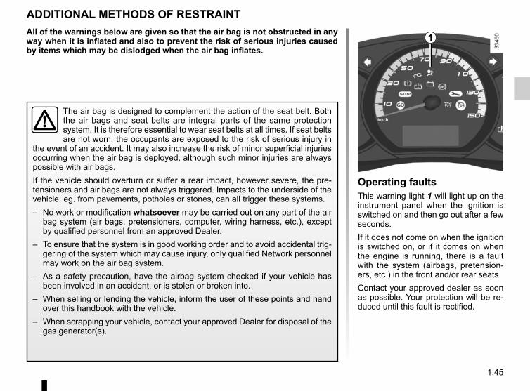
Operating faultsThis warning light 1 will light up on the instrument panel when the ignition is switched on and then go out after a few seconds.If it does not come on when the ignition is switched on, or if it comes on when the engine is running, there is a fault with the system (airbags, pretension-ers, etc.) in the front and/or rear seats.Contact your approved dealer as soon as possible. Your protection will be re-duced until this fault is rectified.
1
1.46
CHILD SAFETY: General information (1/2)
Carrying childrenPlease ensure that you comply with the legislation of your country.Children, and adults, must be correctly seated and strapped in for all journeys. The children being carried in your vehi-cle are your responsibility.A child is not a miniature adult. Children are at risk of specific injuries as their muscles and bones have not yet fin-ished growing. The seat belt alone would not provide suitable protection. Use an approved child seat and ensure you use it correctly.
A collision at 30 mph (50 km/h) is the same as fall-ing a distance of 10 metres. Transporting a child without
a restraint is the equivalent of allow-ing him or her to play on a fourth-floor balcony without railings.Never travel with a child held in your arms. In the event of an accident, you will not be able to keep hold of the child, even if you yourself are wearing a seat belt.If your vehicle has been involved in a road accident, replace the child seat and have the seat belts and ISOFIX anchorage points checked.
To prevent the doors being opened, use the “Child safety” device (refer to the information on “Opening
and closing the doors” in Section 1).
Driver’s responsibility when parking or stopping the vehicleNever leave an animal,
child or adult who is not self-suffi-cient alone on your vehicle, even for a short time.They may pose a risk to themselves or to others by starting the engine, activating equipment such as the electric windows or by locking the doors.Also, in hot and/or sunny weather, please remember that the tempera-ture inside the passenger compart-ment increases very quickly.RISK OF DEATH OR SERIOUS INJURY.
1.47
CHILD SAFETY: General information (2/2)
Using a child seatThe level of protection offered by the child seat depends on its ability to re-strain your child and on its installation. Incorrect installation compromises the protection it offers the child in the event of harsh braking or an impact.Before purchasing a child seat, check that it complies with the regulations for the country you are in and that it can be fitted in your vehicle. Consult an ap-proved dealer to find out which seats are recommended for your vehicle.Before fitting a child seat, read the manual and respect its instructions. If you experience any difficulties during installation, contact the manufacturer of the equipment. Keep the instructions with the seat.
Set a good example by always fas-tening your seat belt and teaching your child:– to strap themselves in correctly.– to always get in and out of the car
at the kerb, away from busy traf-fic.
Do not use a second-hand child seat or one without an instruction manual.Check that there are no objects in the vicinity of the child seat which could impede its operation.
Never leave a child unat-tended in the vehicle.Check that your child is always strapped in and that
the belt or safety harness used is correctly set and adjusted. Avoid wearing bulky clothing which could cause the belts to slacken.Never let your child put their head or arms out of the window.Check that the child is in the correct position for the entire journey, espe-cially if asleep.
1.48
CHILD SAFETY: choosing a child seat
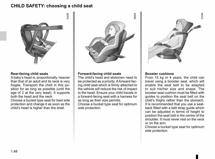
Rear-facing child seatsA baby’s head is, proportionally, heavier than that of an adult and its neck is very fragile. Transport the child in this po-sition for as long as possible (until the age of 2 at the very least). It supports both the head and the neck.Choose a bucket type seat for best side protection and change it as soon as the child’s head is higher than the shell.
Forward-facing child seatsThe child’s head and abdomen need to be protected as a priority. A forward-fac-ing child seat which is firmly attached to the vehicle will reduce the risk of impact to the head. Ensure your child travels in a forward-facing seat with a harness for as long as their size permits.Choose a bucket type seat for optimum side protection.
Booster cushionsFrom 15 kg or 4 years, the child can travel using a booster seat, which will enable the seat belt to be adapted to suit his/her size and shape. The booster seat cushion must be fitted with guides to position the seat belt on the child’s thighs rather than the stomach. It is recommended that you use a seat-back fitted with a belt strap guide which can be adjusted in terms of height to position the seat belt in the centre of the shoulder. It must never rest on the neck or on the arm.Choose a bucket type seat for optimum side protection.
1.49
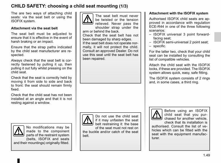
CHILD SAFETY: choosing a child seat mounting (1/3)The are two ways of attaching child seats: via the seat belt or using the ISOFIX system.
Attachment via the seat beltThe seat belt must be adjusted to ensure that it is effective in the event of harsh braking or an impact.Ensure that the strap paths indicated by the child seat manufacturer are re-spected.Always check that the seat belt is cor-rectly fastened by pulling it up, then pulling it out fully whilst pressing on the child seat.Check that the seat is correctly held by moving it from side to side and back to front: the seat should remain firmly fixed.Check that the child seat has not been installed at an angle and that it is not resting against a window.
Attachment with the ISOFIX systemAuthorised ISOFIX child seats are ap-proved in accordance with regulation ECE-R44 in one of the three following scenarios:– ISOFIX universal 3 point forward-
facing seat;– ISOFIX semi-universal 2 point seat;– specific.For the latter two, check that your child seat can be installed by consulting the list of compatible vehicles.Attach the child seat with the ISOFIX locks, if these are provided. The ISOFIX system allows quick, easy, safe fitting.The ISOFIX system consists of 2 rings and, in some cases, a third ring.
Before using an ISOFIX child seat that you pur-chased for another vehicle, check that its installation is
authorised. Consult the list of ve-hicles which can be fitted with the seat with the equipment manufac-turer.
No modifications may be made to the component parts of the restraint system (belts, ISOFIX and seats
and their mountings) originally fitted.
The seat belt must never be twisted or the tension relieved. Never pass the shoulder strap under the
arm or behind the back.Check that the seat belt has not been damaged by sharp edges.If the seat belt does not operate nor-mally, it will not protect the child. Consult an approved Dealer. Do not use this seat until the seat belt has been repaired.
Do not use the child seat if it may unfasten the seat belt restraining it: the base of the seat must not rest on
the buckle and/or catch of the seat belt.
1.50
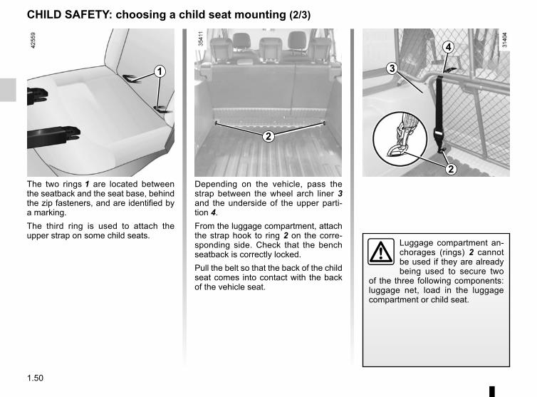
The two rings 1 are located between the seatback and the seat base, behind the zip fasteners, and are identified by a marking.The third ring is used to attach the upper strap on some child seats.
2
CHILD SAFETY: choosing a child seat mounting (2/3)
Depending on the vehicle, pass the strap between the wheel arch liner 3 and the underside of the upper parti-tion 4.From the luggage compartment, attach the strap hook to ring 2 on the corre-sponding side. Check that the bench seatback is correctly locked.Pull the belt so that the back of the child seat comes into contact with the back of the vehicle seat.
3
4
2
1
Luggage compartment an-chorages (rings) 2 cannot be used if they are already being used to secure two
of the three following components: luggage net, load in the luggage compartment or child seat.
1.51
The ISOFIX anchorage points have been exclu-sively designed for child seats with the ISOFIX
system. Never fit a different type of child seat, seat belt or other objects to these anchorage points.Check that nothing is obstructing the anchorage points.If your vehicle has been involved in a road accident, have the ISOFIX anchorage points checked and re-place your child seat.
The child seat strap must be attached to the corre-sponding ring.Do not use any other
mounting point.
CHILD SAFETY: choosing a child seat mounting (3/3)
1.52
Some seats are not suitable for fitting child seats. The diagrams on the fol-lowing pages show you how to attach a child seat.The types of child seats indicated may not be available. Before using a differ-ent child seat, check with the manufac-turer that it can be fitted.
CHILD SAFETY: fitting a child seat (1/6)In the front seatThe laws concerning children travel-ling in the front passenger seat differ in every country. Consult the legislation in force and follow the indications on the diagrams on the following pages.Before fitting a child seat in this seat (if authorised):– lower the seat belt as far as possible;– move the seat as far back as possi-
ble;– gently tilt the seatback away from
vertical (approximately 25°);– on equipped vehicles, raise the seat
base as far as possible.In all situations, reinsert the headrest to its full extent so that it does not interfere with the child seat (see the information on “Front headrests” in Section 1);
RISK OF DEATH OR SERIOUS INJURY: before installing a child seat on this seat, check that the airbag
has been deactivated (refer to “Child safety: front passenger airbag deac-tivation/activation” in Section 1).
Fit the child seat in a rear seat wherever possible.Check that when installing the child seat in the vehicle
it is not at risk of coming loose from its base.If you have to remove the headrest, check that it is correctly stored so that it does not come loose under harsh braking or impact.Always attach the child seat to the vehicle even if it is not in use so that it does not come loose under harsh braking or impact.
After installing the child seat, when this is possible, you can move the vehi-cle seat forward if necessary (so as to leave enough space in the rear seats for passengers or other child seats). In the case of a rear-facing child seat, do not let it touch the dashboard or move it to the furthest forward position.Do not change these settings after the child seat is installed.
1.53
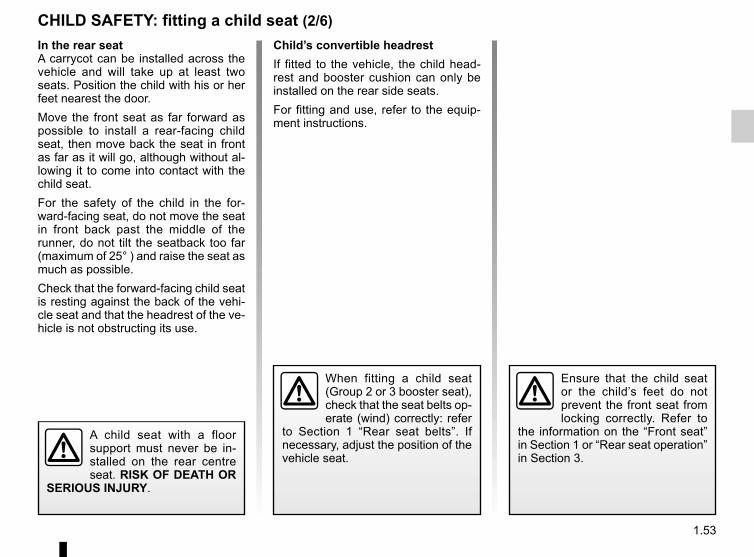
In the rear seatA carrycot can be installed across the vehicle and will take up at least two seats. Position the child with his or her feet nearest the door.Move the front seat as far forward as possible to install a rear-facing child seat, then move back the seat in front as far as it will go, although without al-lowing it to come into contact with the child seat.For the safety of the child in the for-ward-facing seat, do not move the seat in front back past the middle of the runner, do not tilt the seatback too far (maximum of 25° ) and raise the seat as much as possible.Check that the forward-facing child seat is resting against the back of the vehi-cle seat and that the headrest of the ve-hicle is not obstructing its use.
CHILD SAFETY: fitting a child seat (2/6)Child’s convertible headrestIf fitted to the vehicle, the child head-rest and booster cushion can only be installed on the rear side seats.For fitting and use, refer to the equip-ment instructions.
A child seat with a floor support must never be in-stalled on the rear centre seat. RISK OF DEATH OR
SERIOUS INJURY.
When fitting a child seat (Group 2 or 3 booster seat), check that the seat belts op-erate (wind) correctly: refer
to Section 1 “Rear seat belts”. If necessary, adjust the position of the vehicle seat.
Ensure that the child seat or the child’s feet do not prevent the front seat from locking correctly. Refer to
the information on the “Front seat” in Section 1 or “Rear seat operation” in Section 3.
1.54
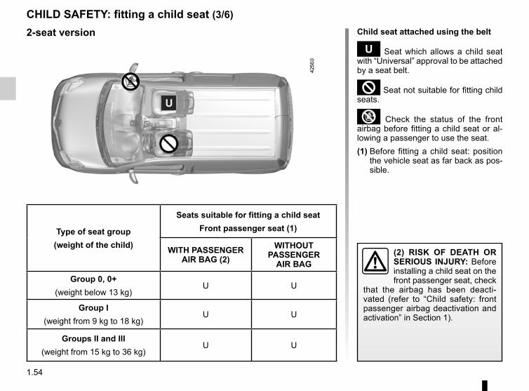
CHILD SAFETY: fitting a child seat (3/6)Child seat attached using the belt
¬ Seat which allows a child seat with “Universal” approval to be attached by a seat belt.
² Seat not suitable for fitting child seats.
³ Check the status of the front airbag before fitting a child seat or al-lowing a passenger to use the seat.(1) Before fitting a child seat: position
the vehicle seat as far back as pos-sible.
Type of seat group(weight of the child)
Seats suitable for fitting a child seatFront passenger seat (1)
WITH PASSENGER AIR BAG (2)
WITHOUT PASSENGER
AIR BAG
Group 0, 0+(weight below 13 kg)
U U
Group I(weight from 9 kg to 18 kg)
U U
Groups II and III(weight from 15 kg to 36 kg)
U U
(2) RISK OF DEATH OR SERIOUS INJURY: Before installing a child seat on the front passenger seat, check
that the airbag has been deacti-vated (refer to “Child safety: front passenger airbag deactivation and activation” in Section 1).
2-seat version
1.55
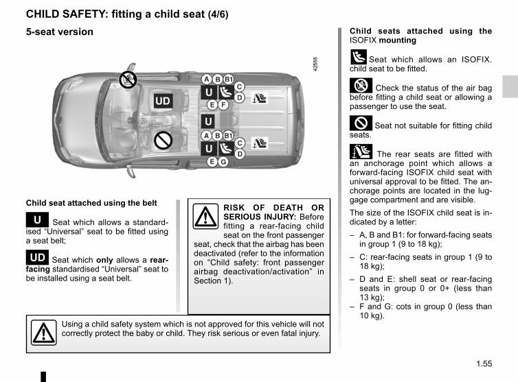
CHILD SAFETY: fitting a child seat (4/6)Child seats attached using the ISOFIX mounting
üSeat which allows an ISOFIX. child seat to be fitted.
³ Check the status of the air bag before fitting a child seat or allowing a passenger to use the seat.
² Seat not suitable for fitting child seats.
± The rear seats are fitted with an anchorage point which allows a forward-facing ISOFIX child seat with universal approval to be fitted. The an-chorage points are located in the lug-gage compartment and are visible.The size of the ISOFIX child seat is in-dicated by a letter:– A, B and B1: for forward-facing seats
in group 1 (9 to 18 kg);– C: rear-facing seats in group 1 (9 to
18 kg);– D and E: shell seat or rear-facing
seats in group 0 or 0+ (less than 13 kg);
– F and G: cots in group 0 (less than 10 kg).
Child seat attached using the belt
¬ Seat which allows a standard-ised “Universal” seat to be fitted using a seat belt;
− Seat which only allows a rear-facing standardised “Universal” seat to be installed using a seat belt.
Using a child safety system which is not approved for this vehicle will not correctly protect the baby or child. They risk serious or even fatal injury.
RISK OF DEATH OR SERIOUS INJURY: Before fitting a rear-facing child seat on the front passenger
seat, check that the airbag has been deactivated (refer to the information on “Child safety: front passenger airbag deactivation/activation” in Section 1).
5-seat version
1.56
CHILD SAFETY: fitting a child seat (5/6)
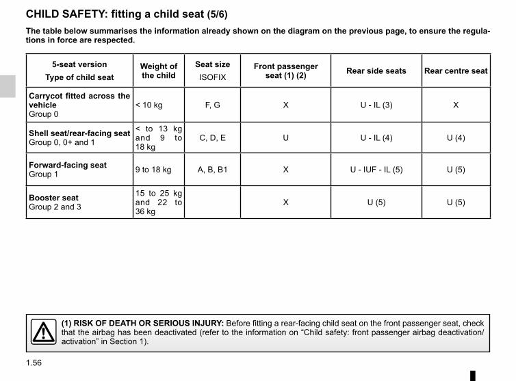
5-seat versionType of child seat
Weight of the child
Seat sizeISOFIX
Front passenger seat (1) (2) Rear side seats Rear centre seat
Carrycot fitted across the vehicleGroup 0
< 10 kg F, G X U - IL (3) X
Shell seat/rear-facing seatGroup 0, 0+ and 1
< to 13 kg and 9 to 18 kg
C, D, E U U - IL (4) U (4)
Forward-facing seatGroup 1 9 to 18 kg A, B, B1 X U - IUF - IL (5) U (5)
Booster seatGroup 2 and 3
15 to 25 kg and 22 to 36 kg
X U (5) U (5)
(1) RISK OF DEATH OR SERIOUS INJURY: Before fitting a rear-facing child seat on the front passenger seat, check that the airbag has been deactivated (refer to the information on “Child safety: front passenger airbag deactivation/activation” in Section 1).
The table below summarises the information already shown on the diagram on the previous page, to ensure the regula-tions in force are respected.
1.57
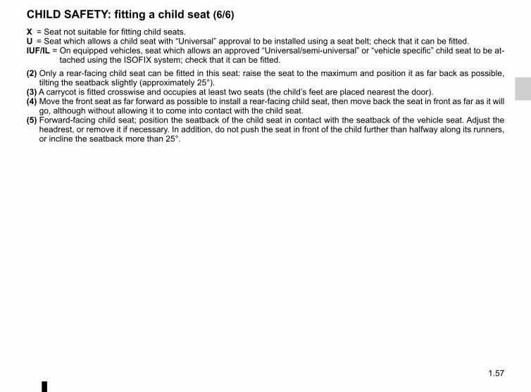
X = Seat not suitable for fitting child seats.U = Seat which allows a child seat with “Universal” approval to be installed using a seat belt; check that it can be fitted.IUF/IL = On equipped vehicles, seat which allows an approved “Universal/semi-universal” or “vehicle specific” child seat to be at-
tached using the ISOFIX system; check that it can be fitted.(2) Only a rear-facing child seat can be fitted in this seat: raise the seat to the maximum and position it as far back as possible,
tilting the seatback slightly (approximately 25°).(3) A carrycot is fitted crosswise and occupies at least two seats (the child’s feet are placed nearest the door).(4) Move the front seat as far forward as possible to install a rear-facing child seat, then move back the seat in front as far as it will
go, although without allowing it to come into contact with the child seat.(5) Forward-facing child seat; position the seatback of the child seat in contact with the seatback of the vehicle seat. Adjust the
headrest, or remove it if necessary. In addition, do not push the seat in front of the child further than halfway along its runners, or incline the seatback more than 25°.
CHILD SAFETY: fitting a child seat (6/6)
1.58
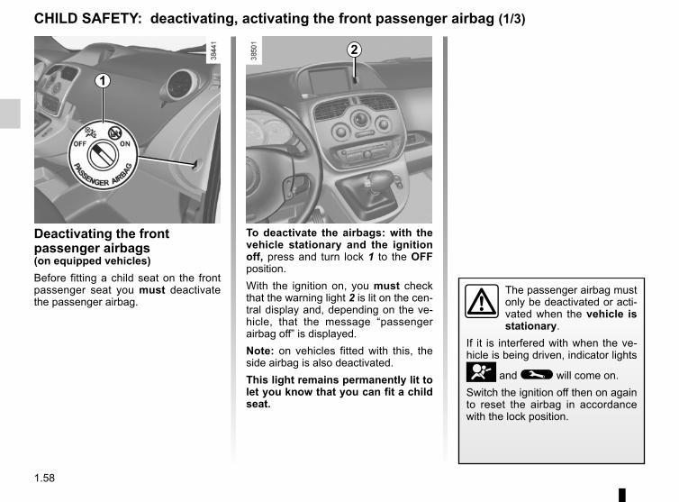
Deactivating the front passenger airbags(on equipped vehicles)Before fitting a child seat on the front passenger seat you must deactivate the passenger airbag.
To deactivate the airbags: with the vehicle stationary and the ignition off, press and turn lock 1 to the OFF position.With the ignition on, you must check that the warning light 2 is lit on the cen-tral display and, depending on the ve-hicle, that the message “passenger airbag off” is displayed.Note: on vehicles fitted with this, the side airbag is also deactivated.This light remains permanently lit to let you know that you can fit a child seat.
CHILD SAFETY: deactivating, activating the front passenger airbag (1/3)
The passenger airbag must only be deactivated or acti-vated when the vehicle is stationary.
If it is interfered with when the ve-hicle is being driven, indicator lights
å and © will come on.Switch the ignition off then on again to reset the airbag in accordance with the lock position.
2
1
1.59
CHILD SAFETY: deactivating, activating the front passenger airbag (2/3)
3
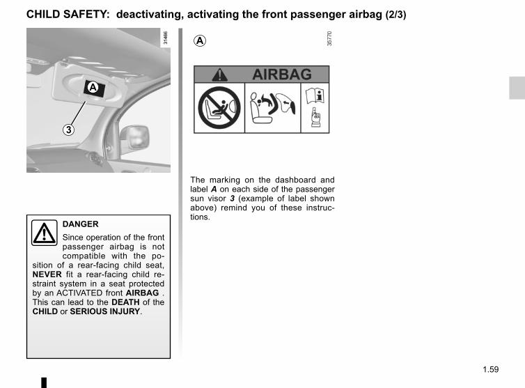
The marking on the dashboard and label A on each side of the passenger sun visor 3 (example of label shown above) remind you of these instruc-tions.
A
A
DANGERSince operation of the front passenger airbag is not compatible with the po-
sition of a rear-facing child seat, NEVER fit a rear-facing child re-straint system in a seat protected by an ACTIVATED front AIRBAG . This can lead to the DEATH of the CHILD or SERIOUS INJURY.
1.60
The passenger airbag must only be deactivated or acti-vated when the vehicle is stationary.
If it is interfered with when the ve-hicle is being driven, indicator lights
å and © will come on.Switch the ignition off then on again to reset the airbag in accordance with the lock position.
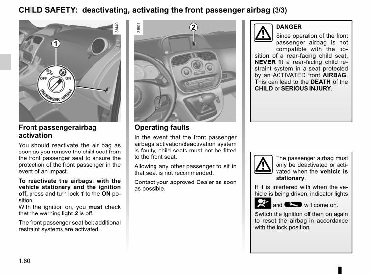
Operating faultsIn the event that the front passenger airbags activation/deactivation system is faulty, child seats must not be fitted to the front seat.Allowing any other passenger to sit in that seat is not recommended.Contact your approved Dealer as soon as possible.
Front passengerairbag activationYou should reactivate the air bag as soon as you remove the child seat from the front passenger seat to ensure the protection of the front passenger in the event of an impact.To reactivate the airbags: with the vehicle stationary and the ignition off, press and turn lock 1 to the ON po-sition.With the ignition on, you must check that the warning light 2 is off.The front passenger seat belt additional restraint systems are activated.
2
CHILD SAFETY: deactivating, activating the front passenger airbag (3/3)
1
DANGERSince operation of the front passenger airbag is not compatible with the po-
sition of a rear-facing child seat, NEVER fit a rear-facing child re-straint system in a seat protected by an ACTIVATED front AIRBAG. This can lead to the DEATH of the CHILD or SERIOUS INJURY.
1.61
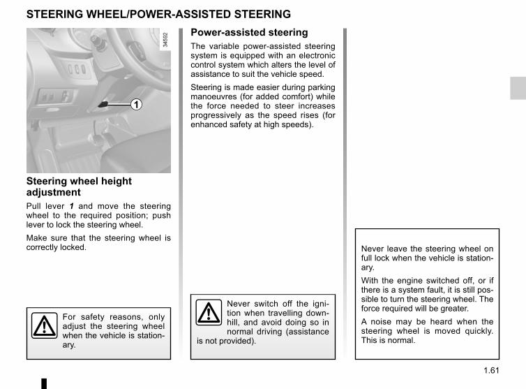
STEERING WHEEL/POWER-ASSISTED STEERING
Steering wheel height adjustmentPull lever 1 and move the steering wheel to the required position; push lever to lock the steering wheel.Make sure that the steering wheel is correctly locked.
For safety reasons, only adjust the steering wheel when the vehicle is station-ary.
1
Never switch off the igni-tion when travelling down-hill, and avoid doing so in normal driving (assistance
is not provided).
Power-assisted steeringThe variable power-assisted steering system is equipped with an electronic control system which alters the level of assistance to suit the vehicle speed.Steering is made easier during parking manoeuvres (for added comfort) while the force needed to steer increases progressively as the speed rises (for enhanced safety at high speeds).
Never leave the steering wheel on full lock when the vehicle is station-ary.With the engine switched off, or if there is a system fault, it is still pos-sible to turn the steering wheel. The force required will be greater.A noise may be heard when the steering wheel is moved quickly. This is normal.
1.62
DRIVING POSITION, LEFT-HAND DRIVE (1/2)
4 6 13
21
20
3 12
16
111
1724
2 7 8 1095
23 1526 2225 14
18
19
1.63
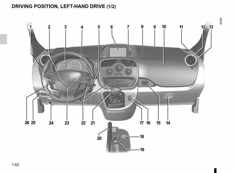
21 Gear lever.
22 Remote control/location for radio, navigation system.
23 Cruise control/speed limiter con-trols.
24 Bonnet release control.
25 Controls for:– Vertical headlight adjustment;– Parking distance control.
26 Controls for:– Cruise control/speed limiter;– Activating/deactivating the pe-
destrian horn;– additional heating.
1 Stalk for:– direction indicator lights;– exterior lights;– front fog lights;– rear fog lights.
2 – Horn,– location for driver’s air bag.
3 Instrument panel.
4 Stalk for:– windscreen wipers;– windscreen washer;– trip computer and warning
system.
5 Ignition switch.
6 Multimedia display or touchscreen:– seat belt reminder warning light;– airbag deactivation warning
light;– navigation;– clock;– exterior temperature.
7 Centre air vent.
8 Controls for ventilation, heating and de-icing.
9 Windscreen demister outlet.
10 Location for passenger air bag.
11 Speaker.
12 Side air vent.
13 Side window demister outlet.
14 Glove box.
15 Storage space or accessories socket.
16 Hazard warning lights switch.
17 Central door locking/unlocking switch.
18 ECO mode switch.
19 Cigarette lighter or accessories socket.
20 Handbrake.
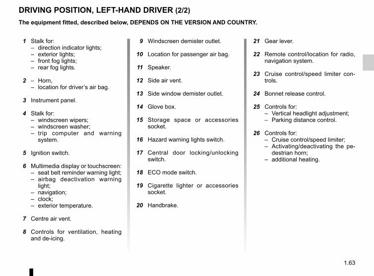
DRIVING POSITION, LEFT-HAND DRIVER (2/2)The equipment fitted, described below, DEPENDS ON THE VERSION AND COUNTRY.
1.64
DRIVING POSITION: RIGHT-HAND DRIVE (1/2)
4 6
23
3 12
1520
111
1821
2
25
7 8 109
26 1416
5
1719272829
2224
13
1.65
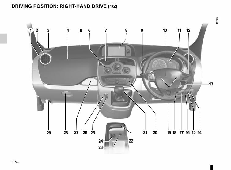
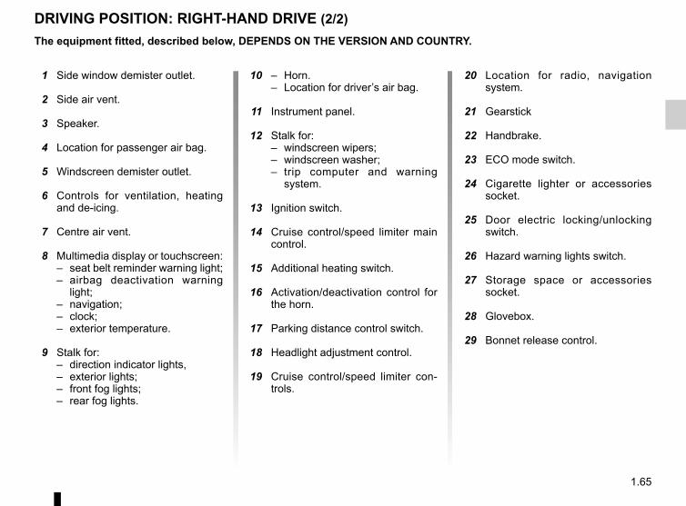
DRIVING POSITION: RIGHT-HAND DRIVE (2/2)
20 Location for radio, navigation system.
21 Gearstick
22 Handbrake.
23 ECO mode switch.
24 Cigarette lighter or accessories socket.
25 Door electric locking/unlocking switch.
26 Hazard warning lights switch.
27 Storage space or accessories socket.
28 Glovebox.
29 Bonnet release control.
10 – Horn.– Location for driver’s air bag.
11 Instrument panel.
12 Stalk for:– windscreen wipers;– windscreen washer;– trip computer and warning
system.
13 Ignition switch.
14 Cruise control/speed limiter main control.
15 Additional heating switch.
16 Activation/deactivation control for the horn.
17 Parking distance control switch.
18 Headlight adjustment control.
19 Cruise control/speed limiter con-trols.
1 Side window demister outlet.
2 Side air vent.
3 Speaker.
4 Location for passenger air bag.
5 Windscreen demister outlet.
6 Controls for ventilation, heating and de-icing.
7 Centre air vent.
8 Multimedia display or touchscreen:– seat belt reminder warning light;– airbag deactivation warning
light;– navigation;– clock;– exterior temperature.
9 Stalk for:– direction indicator lights,– exterior lights;– front fog lights;– rear fog lights.
The equipment fitted, described below, DEPENDS ON THE VERSION AND COUNTRY.
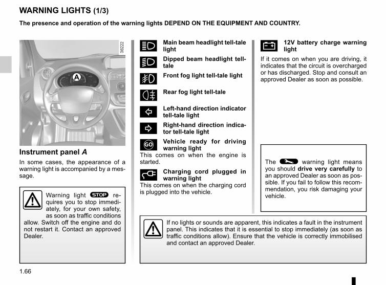
1.66
Ú 12V battery charge warning light
If it comes on when you are driving, it indicates that the circuit is overcharged or has discharged. Stop and consult an approved Dealer as soon as possible.
Instrument panel AIn some cases, the appearance of a warning light is accompanied by a mes-sage.
WARNING LIGHTS (1/3)
If no lights or sounds are apparent, this indicates a fault in the instrument panel. This indicates that it is essential to stop immediately (as soon as traffic conditions allow). Ensure that the vehicle is correctly immobilised and contact an approved Dealer.
A
Warning light ® re-quires you to stop immedi-ately, for your own safety, as soon as traffic conditions
allow. Switch off the engine and do not restart it. Contact an approved Dealer.
The presence and operation of the warning lights DEPEND ON THE EQUIPMENT AND COUNTRY.
The © warning light means you should drive very carefully to an approved Dealer as soon as pos-sible. If you fail to follow this recom-mendation, you risk damaging your vehicle.
á Main beam headlight tell-tale light
k Dipped beam headlight tell-tale
g Front fog light tell-tale light
Rear fog light tell-tale
c Left-hand direction indicator tell-tale light
b Right-hand direction indica-tor tell-tale light
Vehicle ready for driving warning light
This comes on when the engine is started.
Charging cord plugged in warning light
This comes on when the charging cord is plugged into the vehicle.
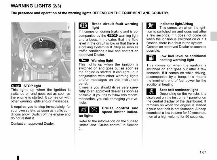
1.67
WARNING LIGHTS (2/3)The presence and operation of the warning lights DEPEND ON THE EQUIPMENT AND COUNTRY.
å Indicator lightAirbagThis comes on when the igni-
tion is switched on and goes out after a few seconds. If it does not come on when the ignition is switched on or if it flashes, there is a fault in the system.Contact an approved Dealer as soon as possible.
L Low fuel level or additional heating warning light
This comes on when the ignition is switched on and goes out after a few seconds. If it comes on while driving, accompanied by a beep, this means the imminent end of fuel power for the additional heating.
™ Seat belt reminder lightDepending on the vehicle, it is
displayed on the instrument panel or on the central display of the dashboard. It remains on when the engine is started if your seat belt is not fastened. A beep sounds at a low volume for 30 seconds, then at a high volume for 90 seconds.
D Brake circuit fault warning light
If it comes on during braking and is ac-companied by the ® warning light and a beep, it indicates that the fluid level in the circuit is low or that there is a braking system fault. Stop as soon as traffic conditions allow and contact an approved Dealer.
© Warning lightThis lights up when the ignition is switched on and goes out as soon as the engine is started. It can light up in conjunction with other warning lights and/or messages on the instrument panel.It means you should drive very care-fully to an approved dealer as soon as possible. If you fail to follow this recom-mendation, you risk damaging your ve-hicle.
Ð Ï Cruise control and speed limiter indica-
tor lightsRefer to the information on the “Speed limiter” and “Cruise control” in Section 2.
® STOP lightThis lights up when the ignition is switched on and goes out as soon as the engine is started. It comes on with other warning lights and/or messages.It requires you to stop immediately, for your own safety, as soon as traffic con-ditions allow. Switch off the engine and do not restart it.Contact an approved Dealer.
A
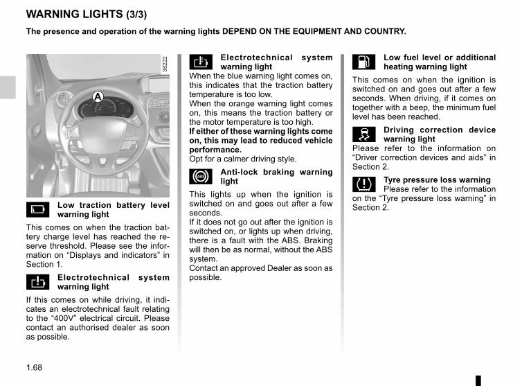
1.68
WARNING LIGHTS (3/3)The presence and operation of the warning lights DEPEND ON THE EQUIPMENT AND COUNTRY.
Electrotechnical system warning light
When the blue warning light comes on, this indicates that the traction battery temperature is too low.When the orange warning light comes on, this means the traction battery or the motor temperature is too high.If either of these warning lights come on, this may lead to reduced vehicle performance.Opt for a calmer driving style.
x Anti-lock braking warning light
This lights up when the ignition is switched on and goes out after a few seconds.If it does not go out after the ignition is switched on, or lights up when driving, there is a fault with the ABS. Braking will then be as normal, without the ABS system.Contact an approved Dealer as soon as possible.
Low traction battery level warning light
This comes on when the traction bat-tery charge level has reached the re-serve threshold. Please see the infor-mation on “Displays and indicators” in Section 1.
Electrotechnical system warning light
If this comes on while driving, it indi-cates an electrotechnical fault relating to the “400V” electrical circuit. Please contact an authorised dealer as soon as possible.
A
L Low fuel level or additional heating warning light
This comes on when the ignition is switched on and goes out after a few seconds. When driving, if it comes on together with a beep, the minimum fuel level has been reached.
Driving correction device warning light
Please refer to the information on “Driver correction devices and aids” in Section 2.
Tyre pressure loss warningPlease refer to the information
on the “Tyre pressure loss warning” in Section 2.
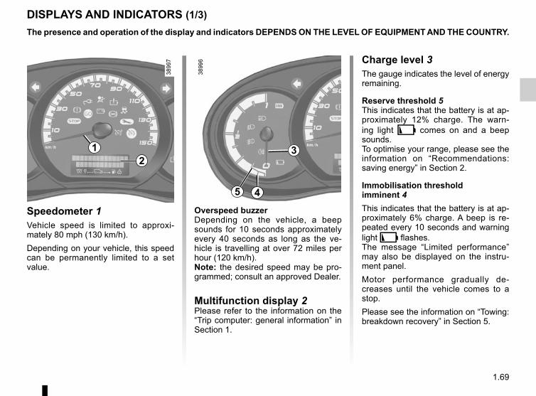
1.69
DISPLAYS AND INDICATORS (1/3)
Overspeed buzzerDepending on the vehicle, a beep sounds for 10 seconds approximately every 40 seconds as long as the ve-hicle is travelling at over 72 miles per hour (120 km/h).Note: the desired speed may be pro-grammed; consult an approved Dealer.
Multifunction display 2Please refer to the information on the “Trip computer: general information” in Section 1.
Speedometer 1Vehicle speed is limited to approxi-mately 80 mph (130 km/h).Depending on your vehicle, this speed can be permanently limited to a set value.
1
The presence and operation of the display and indicators DEPENDS ON THE LEVEL OF EQUIPMENT AND THE COUNTRY.
3
Charge level 3The gauge indicates the level of energy remaining.
Reserve threshold 5This indicates that the battery is at ap-proximately 12% charge. The warn-ing light Ṏ comes on and a beep sounds.To optimise your range, please see the information on “Recommendations: saving energy” in Section 2.
Immobilisation threshold imminent 4This indicates that the battery is at ap-proximately 6% charge. A beep is re-peated every 10 seconds and warning light Ṏ flashes. The message “Limited performance” may also be displayed on the instru-ment panel.Motor performance gradually de-creases until the vehicle comes to a stop.Please see the information on “Towing: breakdown recovery” in Section 5.
5 4
2
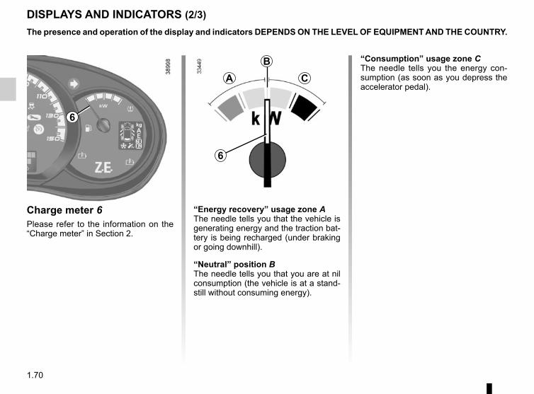
1.70
DISPLAYS AND INDICATORS (2/3)
Charge meter 6Please refer to the information on the “Charge meter” in Section 2.
The presence and operation of the display and indicators DEPENDS ON THE LEVEL OF EQUIPMENT AND THE COUNTRY.
AB
C
6
“Energy recovery” usage zone AThe needle tells you that the vehicle is generating energy and the traction bat-tery is being recharged (under braking or going downhill).
“Neutral” position B The needle tells you that you are at nil consumption (the vehicle is at a stand-still without consuming energy).
“Consumption” usage zone CThe needle tells you the energy con-sumption (as soon as you depress the accelerator pedal).
6
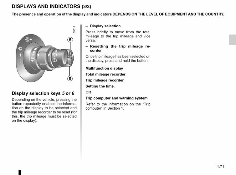
1.71
DISPLAYS AND INDICATORS (3/3)
Display selection keys 5 or 6Depending on the vehicle, pressing the button repeatedly enables the informa-tion on the display to be selected and the trip mileage recorder to be reset (for this, the trip mileage must be selected on the display).
– Display selectionPress briefly to move from the total mileage to the trip mileage and vice versa.– Resetting the trip mileage re-
corderOnce trip mileage has been selected on the display, press and hold the button.
Multifunction displayTotal mileage recorder.Trip mileage recorder.Setting the time.ORTrip computer and warning systemRefer to the information on the “Trip computer” in Section 1.
The presence and operation of the display and indicators DEPENDS ON THE LEVEL OF EQUIPMENT AND THE COUNTRY.
5
6
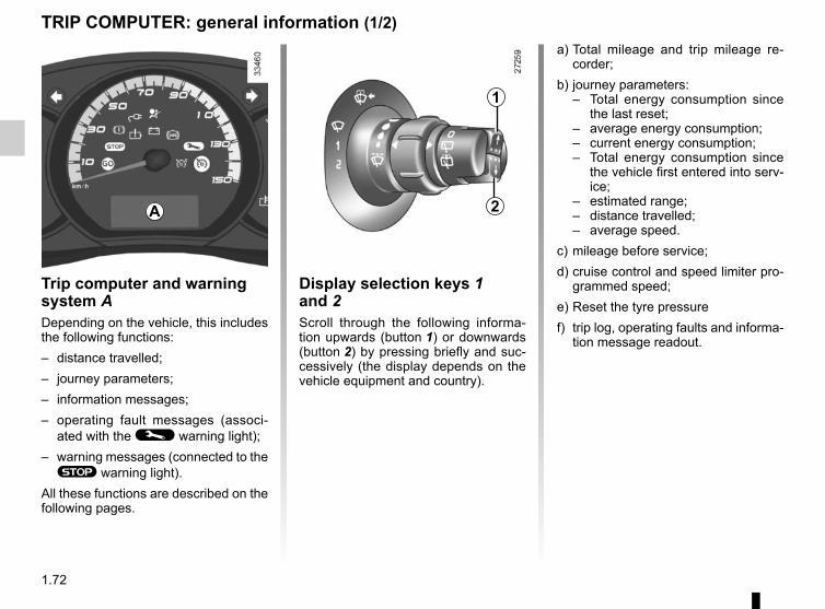
1.72
TRIP COMPUTER: general information (1/2)
Trip computer and warning system ADepending on the vehicle, this includes the following functions:– distance travelled;– journey parameters;– information messages;– operating fault messages (associ-
ated with the © warning light);– warning messages (connected to the ® warning light).
All these functions are described on the following pages.
a) Total mileage and trip mileage re-corder;
b) journey parameters:– Total energy consumption since
the last reset;– average energy consumption;– current energy consumption;– Total energy consumption since
the vehicle first entered into serv-ice;
– estimated range;– distance travelled;– average speed.
c) mileage before service;d) cruise control and speed limiter pro-
grammed speed;e) Reset the tyre pressuref) trip log, operating faults and informa-
tion message readout.
A
1
2
Display selection keys 1 and 2Scroll through the following informa-tion upwards (button 1) or downwards (button 2) by pressing briefly and suc-cessively (the display depends on the vehicle equipment and country).
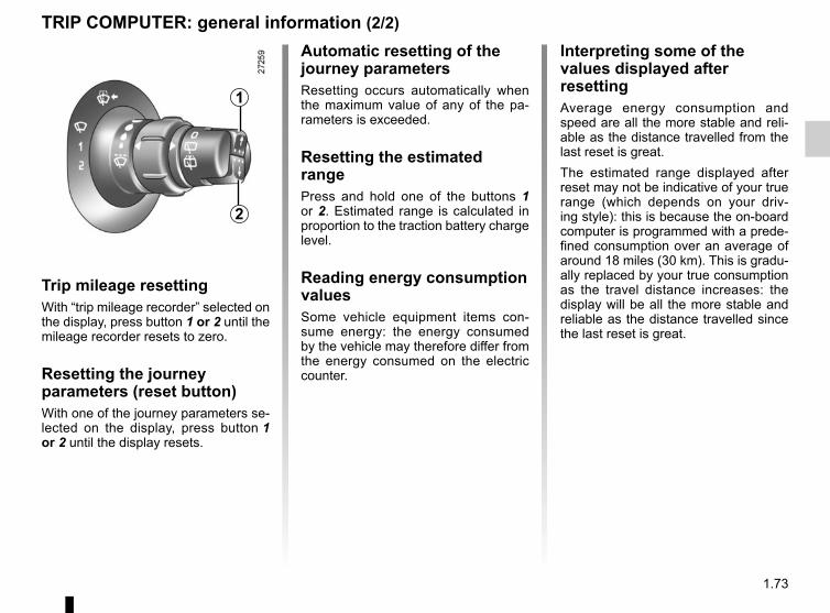
1.73
Trip mileage resettingWith “trip mileage recorder” selected on the display, press button 1 or 2 until the mileage recorder resets to zero.
Resetting the journey parameters (reset button)With one of the journey parameters se-lected on the display, press button 1 or 2 until the display resets.
Interpreting some of the values displayed after resettingAverage energy consumption and speed are all the more stable and reli-able as the distance travelled from the last reset is great.The estimated range displayed after reset may not be indicative of your true range (which depends on your driv-ing style): this is because the on-board computer is programmed with a prede-fined consumption over an average of around 18 miles (30 km). This is gradu-ally replaced by your true consumption as the travel distance increases: the display will be all the more stable and reliable as the distance travelled since the last reset is great.
1
2
TRIP COMPUTER: general information (2/2)
Automatic resetting of the journey parametersResetting occurs automatically when the maximum value of any of the pa-rameters is exceeded.
Resetting the estimated rangePress and hold one of the buttons 1 or 2. Estimated range is calculated in proportion to the traction battery charge level.
Reading energy consumption valuesSome vehicle equipment items con-sume energy: the energy consumed by the vehicle may therefore differ from the energy consumed on the electric counter.
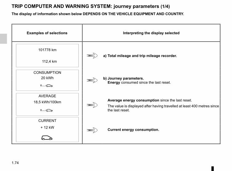
1.74
TRIP COMPUTER AND WARNING SYSTEM: journey parameters (1/4)
Examples of selections Interpreting the display selected
a) Total mileage and trip mileage recorder.101778 km
112,4 km
CONSUMPTIONb) Journey parameters.
Energy consumed since the last reset.20 kWh
AVERAGEAverage energy consumption since the last reset.The value is displayed after having travelled at least 400 metres since the last reset.
18,5 kWh/100km
CURRENT
Current energy consumption.+ 12 kW
The display of information shown below DEPENDS ON THE VEHICLE EQUIPMENT AND COUNTRY.
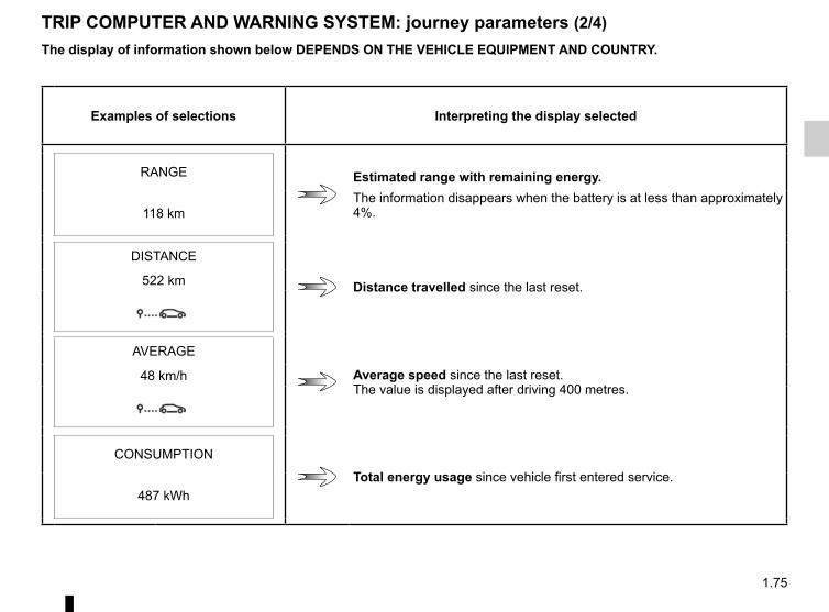
1.75
TRIP COMPUTER AND WARNING SYSTEM: journey parameters (2/4)
Examples of selections Interpreting the display selected
RANGE Estimated range with remaining energy.The information disappears when the battery is at less than approximately 4%.118 km
DISTANCE
Distance travelled since the last reset.522 km
AVERAGE
Average speed since the last reset.The value is displayed after driving 400 metres.
48 km/h
CONSUMPTION
Total energy usage since vehicle first entered service.487 kWh
The display of information shown below DEPENDS ON THE VEHICLE EQUIPMENT AND COUNTRY.
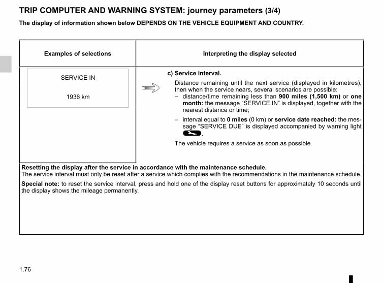
1.76
TRIP COMPUTER AND WARNING SYSTEM: journey parameters (3/4)The display of information shown below DEPENDS ON THE VEHICLE EQUIPMENT AND COUNTRY.
Examples of selections Interpreting the display selected
SERVICE INc) Service interval.
Distance remaining until the next service (displayed in kilometres), then when the service nears, several scenarios are possible:– distance/time remaining less than 900 miles (1,500 km) or one
month: the message “SERVICE IN” is displayed, together with the nearest distance or time;
– interval equal to 0 miles (0 km) or service date reached: the mes-sage “SERVICE DUE” is displayed accompanied by warning light ©.
The vehicle requires a service as soon as possible.
1936 km
Resetting the display after the service in accordance with the maintenance schedule.The service interval must only be reset after a service which complies with the recommendations in the maintenance schedule.Special note: to reset the service interval, press and hold one of the display reset buttons for approximately 10 seconds until the display shows the mileage permanently.
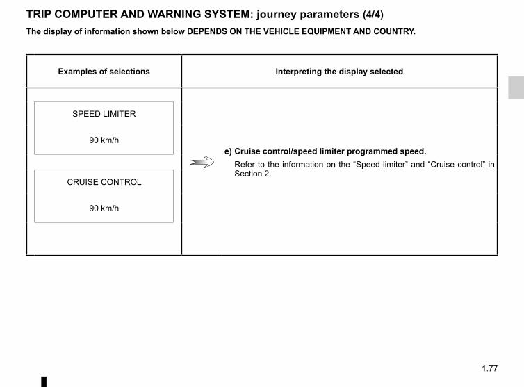
1.77
TRIP COMPUTER AND WARNING SYSTEM: journey parameters (4/4)
Examples of selections Interpreting the display selected
SPEED LIMITER
e) Cruise control/speed limiter programmed speed.Refer to the information on the “Speed limiter” and “Cruise control” in Section 2.
90 km/h
CRUISE CONTROL
90 km/h
The display of information shown below DEPENDS ON THE VEHICLE EQUIPMENT AND COUNTRY.
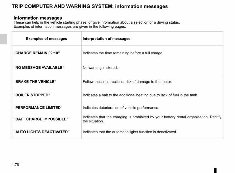
1.78
Information messagesThese can help in the vehicle starting phase, or give information about a selection or a driving status.Examples of information messages are given in the following pages.
Examples of messages Interpretation of messages
“CHARGE REMAIN 02:10” Indicates the time remaining before a full charge.
“NO MESSAGE AVAILABLE” No warning is stored.
“BRAKE THE VEHICLE” Follow these instructions: risk of damage to the motor.
“BOILER STOPPED” Indicates a halt to the additional heating due to lack of fuel in the tank.
“PERFORMANCE LIMITED” Indicates deterioration of vehicle performance.
“BATT CHARGE IMPOSSIBLE” Indicates that the charging is prohibited by your battery rental organisation. Rectify the situation.
“AUTO LIGHTS DEACTIVATED” Indicates that the automatic lights function is deactivated.
TRIP COMPUTER AND WARNING SYSTEM: information messages
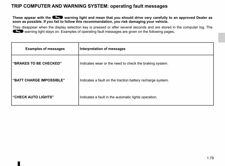
1.79
These appear with the © warning light and mean that you should drive very carefully to an approved Dealer as soon as possible. If you fail to follow this recommendation, you risk damaging your vehicle.They disappear when the display selection key is pressed or after several seconds and are stored in the computer log. The © warning light stays on. Examples of operating fault messages are given on the following pages.
Examples of messages Interpretation of messages
“BRAKES TO BE CHECKED” Indicates wear or the need to check the braking system.
“BATT CHARGE IMPOSSIBLE” Indicates a fault on the traction battery recharge system.
“CHECK AUTO LIGHTS” Indicates a fault in the automatic lights operation.
TRIP COMPUTER AND WARNING SYSTEM: operating fault messages
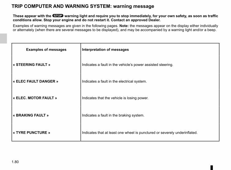
1.80
These appear with the ® warning light and require you to stop immediately, for your own safety, as soon as traffic conditions allow. Stop your engine and do not restart it. Contact an approved Dealer.Examples of warning messages are given in the following pages. Note: the messages appear on the display either individually or alternately (when there are several messages to be displayed), and may be accompanied by a warning light and/or a beep.
Examples of messages Interpretation of messages
« STEERING FAULT » Indicates a fault in the vehicle’s power assisted steering.
« ELEC FAULT DANGER » Indicates a fault in the electrical system.
« ELEC. MOTOR FAULT » Indicates that the vehicle is losing power.
« BRAKING FAULT » Indicates a fault in the braking system.
« TYRE PUNCTURE » Indicates that at least one wheel is punctured or severely underinflated.
TRIP COMPUTER AND WARNING SYSTEM: warning message
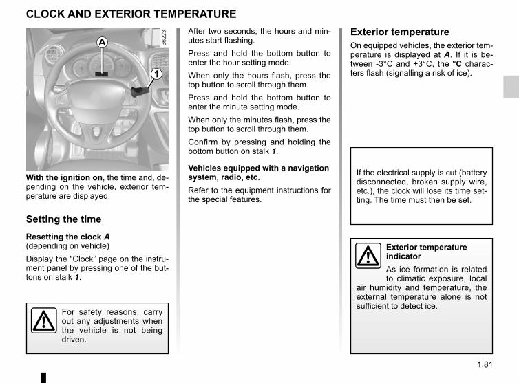
1.81
With the ignition on, the time and, de-pending on the vehicle, exterior tem-perature are displayed.
Setting the timeResetting the clock A(depending on vehicle)Display the “Clock” page on the instru-ment panel by pressing one of the but-tons on stalk 1.
CLOCK AND EXTERIOR TEMPERATURE
Exterior temperature indicatorAs ice formation is related to climatic exposure, local
air humidity and temperature, the external temperature alone is not sufficient to detect ice.
If the electrical supply is cut (battery disconnected, broken supply wire, etc.), the clock will lose its time set-ting. The time must then be set.
A
1
For safety reasons, carry out any adjustments when the vehicle is not being driven.
After two seconds, the hours and min-utes start flashing.Press and hold the bottom button to enter the hour setting mode.When only the hours flash, press the top button to scroll through them.Press and hold the bottom button to enter the minute setting mode.When only the minutes flash, press the top button to scroll through them.Confirm by pressing and holding the bottom button on stalk 1.
Vehicles equipped with a navigation system, radio, etc.Refer to the equipment instructions for the special features.
Exterior temperatureOn equipped vehicles, the exterior tem-perature is displayed at A. If it is be-tween -3°C and +3°C, the °C charac-ters flash (signalling a risk of ice).
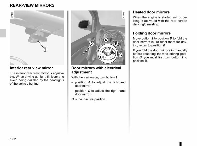
1.82
Interior rear view mirrorThe interior rear view mirror is adjusta-ble. When driving at night, tilt lever 1 to avoid being dazzled by the headlights of the vehicle behind.
REAR-VIEW MIRRORS
1
Heated door mirrorsWhen the engine is started, mirror de-icing is activated with the rear screen de-icing/demisting.
Folding door mirrorsMove button 2 to position D to fold the door mirrors in. To reset them for driv-ing, return to position B.If you fold the door mirrors in manually before resetting them to driving posi-tion B, you must first turn button 2 to position D.
Door mirrors with electrical adjustmentWith the ignition on, turn button 2:– position A to adjust the left-hand
door mirror;– position C to adjust the right-hand
door mirror.B is the inactive position.
B
CD
A2
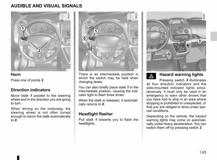
1.83
é Hazard warning lightsPressing switch 3 illuminates
all four direction indicators and the side-mounted indicator lights simul-taneously. It must only be used in an emergency to warn other drivers that you have had to stop in an area where stopping is prohibited or unexpected, or that you are obliged to drive under spe-cial conditions.Depending on the vehicle, the hazard warning lights may come on automati-cally under heavy deceleration. You can switch them off by pressing switch 3.
HornPress one of points 2.
Direction indicatorsMove stalk 1 parallel to the steering wheel and in the direction you are going to turn.When driving on the motorway, the steering wheel is not often turned enough to return the stalk automatically to 0.
There is an intermediate position in which the switch may be held when changing lanes.You can also briefly place stalk 1 in the intermediate position, causing the indi-cator light to flash three times.When the stalk is released, it automati-cally returns to 0.
Headlight flasherPull stalk 1 towards you to flash the headlights.
AUDIBLE AND VISUAL SIGNALS
2
3
1
0
1
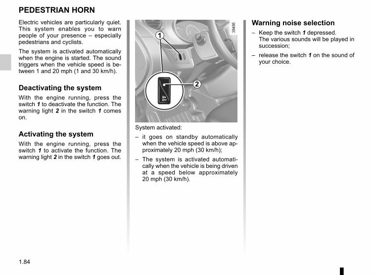
1.84
PEDESTRIAN HORNElectric vehicles are particularly quiet. This system enables you to warn people of your presence – especially pedestrians and cyclists.The system is activated automatically when the engine is started. The sound triggers when the vehicle speed is be-tween 1 and 20 mph (1 and 30 km/h).
Deactivating the systemWith the engine running, press the switch 1 to deactivate the function. The warning light 2 in the switch 1 comes on.
Activating the systemWith the engine running, press the switch 1 to activate the function. The warning light 2 in the switch 1 goes out.
System activated:– it goes on standby automatically
when the vehicle speed is above ap-proximately 20 mph (30 km/h);
– The system is activated automati-cally when the vehicle is being driven at a speed below approximately 20 mph (30 km/h).
Warning noise selection– Keep the switch 1 depressed.
The various sounds will be played in succession;
– release the switch 1 on the sound of your choice.
2
1
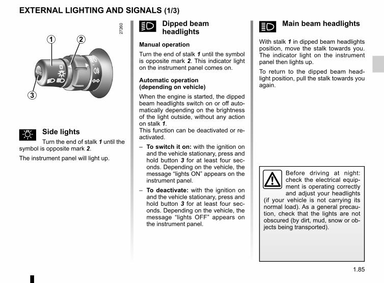
1.85
á Main beam headlights
With stalk 1 in dipped beam headlights position, move the stalk towards you. The indicator light on the instrument panel then lights up.To return to the dipped beam head-light position, pull the stalk towards you again.
u Side lightsTurn the end of stalk 1 until the
symbol is opposite mark 2.The instrument panel will light up.
EXTERNAL LIGHTING AND SIGNALS (1/3)
Before driving at night: check the electrical equip-ment is operating correctly and adjust your headlights
(if your vehicle is not carrying its normal load). As a general precau-tion, check that the lights are not obscured (by dirt, mud, snow or ob-jects being transported).
k Dipped beam headlights
Manual operationTurn the end of stalk 1 until the symbol is opposite mark 2. This indicator light on the instrument panel comes on.
Automatic operation(depending on vehicle)When the engine is started, the dipped beam headlights switch on or off auto-matically depending on the brightness of the light outside, without any action on stalk 1.This function can be deactivated or re-activated.– To switch it on: with the ignition on
and the vehicle stationary, press and hold button 3 for at least four sec-onds. Depending on the vehicle, the message “lights ON” appears on the instrument panel.
– To deactivate: with the ignition on and the vehicle stationary, press and hold button 3 for at least four sec-onds. Depending on the vehicle, the message “lights OFF” appears on the instrument panel.
1 2
3
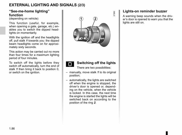
1.86
“See-me-home lighting” function(depending on vehicle)This function (useful, for example, when opening a gate, garage, etc.) en-ables you to switch the dipped head-lights on momentarily.With the ignition off and the headlights off, pull stalk 1 towards you: the dipped beam headlights come on for approxi-mately sixty seconds.This action may be carried out no more than four times for a maximum lighting period of four minutes.To switch off the lights before they switch off automatically, turn the end of stalk 1 then bring it back to position 0, or switch on the ignition.
EXTERNAL LIGHTING AND SIGNALS (2/3)
e Switching off the lightsThere are two possibilities:
– manually, move stalk 1 to its original position;
– automatically, the lights are switched off when the engine is stopped, the driver’s door is opened or, depend-ing on the vehicle, when the vehicle is locked. In this case, the next time the engine is started the lights will be switched back on according to the position of the ring 2.
1 2
Lights-on reminder buzzerA warning beep sounds when the driv-er’s door is opened to warn you that the lights are still on.
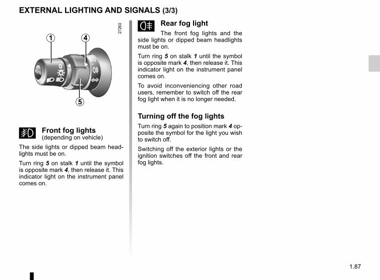
1.87
f Rear fog lightThe front fog lights and the
side lights or dipped beam headlights must be on.Turn ring 5 on stalk 1 until the symbol is opposite mark 4, then release it. This indicator light on the instrument panel comes on.To avoid inconveniencing other road users, remember to switch off the rear fog light when it is no longer needed.
Turning off the fog lightsTurn ring 5 again to position mark 4 op-posite the symbol for the light you wish to switch off.Switching off the exterior lights or the ignition switches off the front and rear fog lights.
g Front fog lights(depending on vehicle)
The side lights or dipped beam head-lights must be on.Turn ring 5 on stalk 1 until the symbol is opposite mark 4, then release it. This indicator light on the instrument panel comes on.
EXTERNAL LIGHTING AND SIGNALS (3/3)
1
5
4
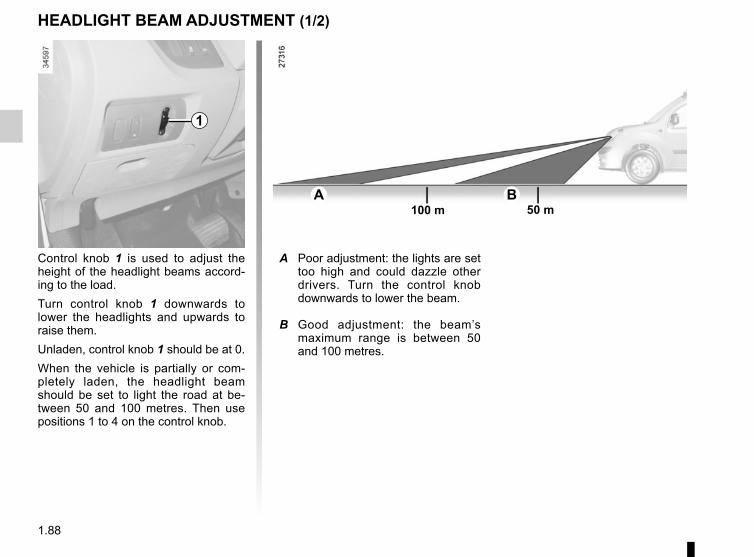
1.88
HEADLIGHT BEAM ADJUSTMENT (1/2)
Control knob 1 is used to adjust the height of the headlight beams accord-ing to the load.Turn control knob 1 downwards to lower the headlights and upwards to raise them.Unladen, control knob 1 should be at 0.When the vehicle is partially or com-pletely laden, the headlight beam should be set to light the road at be-tween 50 and 100 metres. Then use positions 1 to 4 on the control knob.
A B100 m 50 m
A Poor adjustment: the lights are set too high and could dazzle other drivers. Turn the control knob downwards to lower the beam.
B Good adjustment: the beam’s maximum range is between 50 and 100 metres.
1
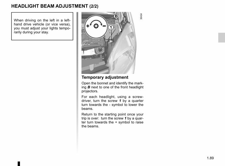
1.89
HEADLIGHT BEAM ADJUSTMENT (2/2)
Temporary adjustmentOpen the bonnet and identify the mark-ing B next to one of the front headlight projectors.For each headlight, using a screw-driver, turn the screw 1 by a quarter turn towards the - symbol to lower the beams.Return to the starting point once your trip is over: turn the screw 1 by a quar-ter turn towards the + symbol to raise the beams.
When driving on the left in a left-hand drive vehicle (or vice versa), you must adjust your lights tempo-rarily during your stay.
B
1
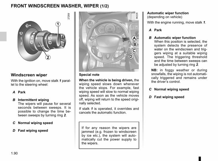
1.90
Windscreen wiperWith the ignition on, move stalk 1 paral-lel to the steering wheel:
A Park
B Intermittent wipingThe wipers will pause for several seconds between sweeps. It is possible to change the time be-tween sweeps by turning ring 2.
C Normal wiping speed
D Fast wiping speed
FRONT WINDSCREEN WASHER, WIPER (1/2)
Special noteWhen the vehicle is being driven, the wiping speed slows down whenever the vehicle stops. For example, fast wiping speed will slow to normal wiping speed. As soon as the vehicle moves off, wiping will return to the speed origi-nally selected.If stalk 1 is operated, it overrides and cancels the automatic function.
If for any reason the wipers are jammed (e.g. frozen to windscreen by ice etc.), the system will auto-matically cut the power supply to the wipers.
ABC
D
1
2
Automatic wiper function(depending on vehicle)With the engine running, move stalk 1.
A Park
B Automatic wiper functionWhen this position is selected, the system detects the presence of water on the windscreen and trig-gers wiping at a suitable wiping speed. The triggering threshold and the time between sweeps can be adjusted by turning ring 2.
NB: in foggy weather or during snowfalls, the wiping is not automati-cally triggered and remains under the driver’s control.
C Normal wiping speed
D Fast wiping speed
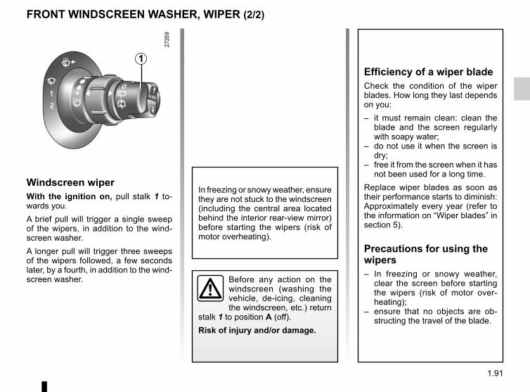
1.91
Windscreen wiperWith the ignition on, pull stalk 1 to-wards you.A brief pull will trigger a single sweep of the wipers, in addition to the wind-screen washer.A longer pull will trigger three sweeps of the wipers followed, a few seconds later, by a fourth, in addition to the wind-screen washer.
FRONT WINDSCREEN WASHER, WIPER (2/2)
1
Before any action on the windscreen (washing the vehicle, de-icing, cleaning the windscreen, etc.) return
stalk 1 to position A (off).Risk of injury and/or damage.
In freezing or snowy weather, ensure they are not stuck to the windscreen (including the central area located behind the interior rear-view mirror) before starting the wipers (risk of motor overheating).
Efficiency of a wiper bladeCheck the condition of the wiper blades. How long they last depends on you:– it must remain clean: clean the
blade and the screen regularly with soapy water;
– do not use it when the screen is dry;
– free it from the screen when it has not been used for a long time.
Replace wiper blades as soon as their performance starts to diminish: Approximately every year (refer to the information on “Wiper blades” in section 5).
Precautions for using the wipers– In freezing or snowy weather,
clear the screen before starting the wipers (risk of motor over-heating);
– ensure that no objects are ob-structing the travel of the blade.
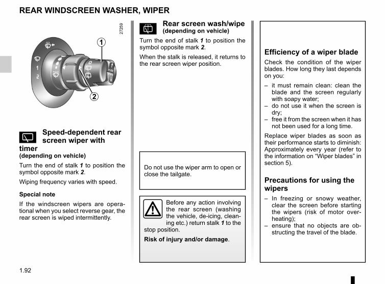
1.92
p Rear screen wash/wipe(depending on vehicle)
Turn the end of stalk 1 to position the symbol opposite mark 2.When the stalk is released, it returns to the rear screen wiper position.
Y Speed-dependent rear screen wiper with
timer(depending on vehicle)Turn the end of stalk 1 to position the symbol opposite mark 2.Wiping frequency varies with speed.
Special noteIf the windscreen wipers are opera-tional when you select reverse gear, the rear screen is wiped intermittently.
REAR WINDSCREEN WASHER, WIPER
1
2
Efficiency of a wiper bladeCheck the condition of the wiper blades. How long they last depends on you:– it must remain clean: clean the
blade and the screen regularly with soapy water;
– do not use it when the screen is dry;
– free it from the screen when it has not been used for a long time.
Replace wiper blades as soon as their performance starts to diminish: Approximately every year (refer to the information on “Wiper blades” in section 5).
Precautions for using the wipers– In freezing or snowy weather,
clear the screen before starting the wipers (risk of motor over-heating);
– ensure that no objects are ob-structing the travel of the blade.
Before any action involving the rear screen (washing the vehicle, de-icing, clean-ing etc.) return stalk 1 to the
stop position.Risk of injury and/or damage.
Do not use the wiper arm to open or close the tailgate.
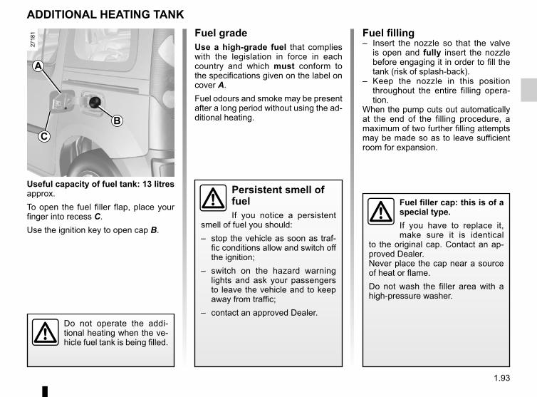
1.93
Useful capacity of fuel tank: 13 litres approx.To open the fuel filler flap, place your finger into recess C.Use the ignition key to open cap B.
ADDITIONAL HEATING TANKFuel gradeUse a high-grade fuel that complies with the legislation in force in each country and which must conform to the specifications given on the label on cover A.Fuel odours and smoke may be present after a long period without using the ad-ditional heating.
A
CB
Fuel filler cap: this is of a special type.If you have to replace it, make sure it is identical
to the original cap. Contact an ap-proved Dealer.Never place the cap near a source of heat or flame.Do not wash the filler area with a high-pressure washer.
Fuel filling– Insert the nozzle so that the valve
is open and fully insert the nozzle before engaging it in order to fill the tank (risk of splash-back).
– Keep the nozzle in this position throughout the entire filling opera-tion.
When the pump cuts out automatically at the end of the filling procedure, a maximum of two further filling attempts may be made so as to leave sufficient room for expansion.
Persistent smell of fuelIf you notice a persistent
smell of fuel you should:– stop the vehicle as soon as traf-
fic conditions allow and switch off the ignition;
– switch on the hazard warning lights and ask your passengers to leave the vehicle and to keep away from traffic;
– contact an approved Dealer.Do not operate the addi-tional heating when the ve-hicle fuel tank is being filled.

1.94
2.1
Section 2: Driving(Advice on use relating to fuel economy and the environment)
Starting, stopping the engine . . . . . . . . . . . . . . . . . . . . . . . . . . . . . . . . . . . . . . . . . . . . . . . . . . . . . . . 2.2Gear control . . . . . . . . . . . . . . . . . . . . . . . . . . . . . . . . . . . . . . . . . . . . . . . . . . . . . . . . . . . . . . . . . . . . 2.4Handbrake . . . . . . . . . . . . . . . . . . . . . . . . . . . . . . . . . . . . . . . . . . . . . . . . . . . . . . . . . . . . . . . . . . . . . 2.5Driving advice, ECO-driving . . . . . . . . . . . . . . . . . . . . . . . . . . . . . . . . . . . . . . . . . . . . . . . . . . . . . . . 2.6Vehicle range: advice . . . . . . . . . . . . . . . . . . . . . . . . . . . . . . . . . . . . . . . . . . . . . . . . . . . . . . . . . . . . 2.8Environment . . . . . . . . . . . . . . . . . . . . . . . . . . . . . . . . . . . . . . . . . . . . . . . . . . . . . . . . . . . . . . . . . . . 2.10Tyre pressure loss warning . . . . . . . . . . . . . . . . . . . . . . . . . . . . . . . . . . . . . . . . . . . . . . . . . . . . . . . . 2.11Driver correction devices/aids . . . . . . . . . . . . . . . . . . . . . . . . . . . . . . . . . . . . . . . . . . . . . . . . . . . . . . 2.15Speed limiter . . . . . . . . . . . . . . . . . . . . . . . . . . . . . . . . . . . . . . . . . . . . . . . . . . . . . . . . . . . . . . . . . . . 2.18Cruise control . . . . . . . . . . . . . . . . . . . . . . . . . . . . . . . . . . . . . . . . . . . . . . . . . . . . . . . . . . . . . . . . . . 2.21Parking distance control . . . . . . . . . . . . . . . . . . . . . . . . . . . . . . . . . . . . . . . . . . . . . . . . . . . . . . . . . . 2.25Reversing camera . . . . . . . . . . . . . . . . . . . . . . . . . . . . . . . . . . . . . . . . . . . . . . . . . . . . . . . . . . . . . . . 2.27
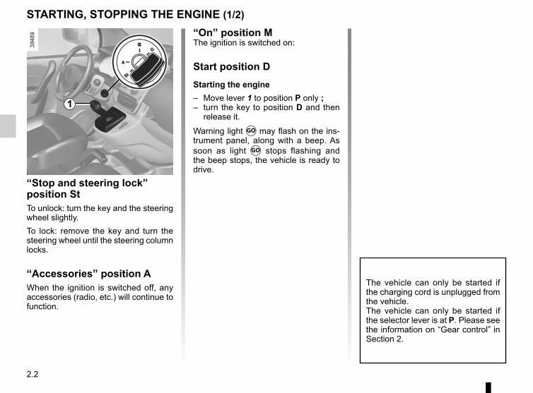
2.2
STARTING, STOPPING THE ENGINE (1/2)
“Stop and steering lock” position StTo unlock: turn the key and the steering wheel slightly.To lock: remove the key and turn the steering wheel until the steering column locks.
“Accessories” position AWhen the ignition is switched off, any accessories (radio, etc.) will continue to function.
The vehicle can only be started if the charging cord is unplugged from the vehicle.The vehicle can only be started if the selector lever is at P. Please see the information on “Gear control” in Section 2.
1
“On” position MThe ignition is switched on:
Start position DStarting the engine– Move lever 1 to position P only ;– turn the key to position D and then
release it.
Warning light Ṑ may flash on the ins-trument panel, along with a beep. As soon as light Ṑ stops flashing and the beep stops, the vehicle is ready to drive.
2.3
Stopping the engineWith the engine running, turn the key back to the “Stop” position St. Warning light Ṑ goes out.
Driver’s responsibility when parking or stopping the vehicleNever leave an animal,
child or adult who is not self-suffi-cient alone in your vehicle, even for a short time.They may pose a risk to themselves or to others by starting the engine, activating equipment such as the electric windows or locking the doors, for example.Also, in hot and/or sunny weather, please remember that the tempera-ture inside the passenger compart-ment increases very quickly.RISK OF DEATH OR SERIOUS INJURY.
Never switch off the igni-tion before the vehicle has come to a complete stop. Switching off the engine di-
sables the assistance equipment: brakes, power-assisted steering, etc., and the passive safety devices such as airbagsand pretensioners.
STARTING, STOPPING THE ENGINE (2/2)
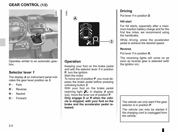
2.4
GEAR CONTROL (1/2)
Operates similar to an automatic gear-box.
Selector lever 1The display A on instrument panel indi-cates the gear lever position as 3.P : ParkR : ReverseN : NeutralD : Forward
OperationKeeping your foot on the brake pedal and with the selector lever 1 in position P, turn the ignition.Start the motor.To move out of position P, you must de-press the brake pedal before pressing unlocking button 2.With your foot on the brake pedal (warning light c in display A goes out), move the lever out of position P.Only engage D or R when the vehi-cle is stopped, with your foot on the brake and the accelerator pedal re-leased.
1
DrivingPut lever 1 in position D.
Hill startFor hill starts, especially after a maxi-mum traction battery charge and for the first few miles, we recommend using the handbrake.While driving, press the accelerator pedal to achieve the desired speed.
ReversePut lever 1 in position R.The reversing lights will come on as soon as reverse gear is selected (with the ignition on).
32
A
The vehicle can only start if the gear selector is in position P.The vehicle can only be started if the charging cord is unplugged from the vehicle.
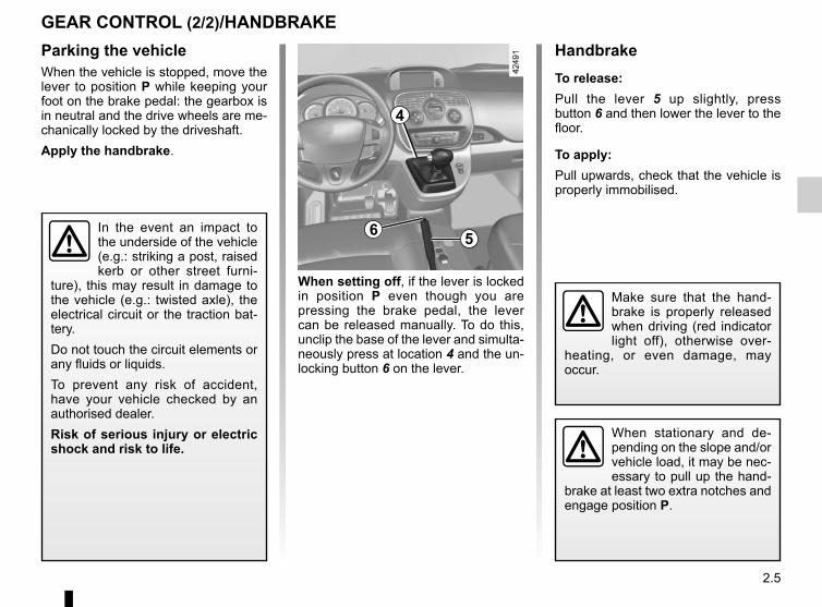
2.5
HandbrakeTo release:Pull the lever 5 up slightly, press button 6 and then lower the lever to the floor.
To apply:Pull upwards, check that the vehicle is properly immobilised.
GEAR CONTROL (2/2)/HANDBRAKEParking the vehicleWhen the vehicle is stopped, move the lever to position P while keeping your foot on the brake pedal: the gearbox is in neutral and the drive wheels are me-chanically locked by the driveshaft.Apply the handbrake.
In the event an impact to the underside of the vehicle (e.g.: striking a post, raised kerb or other street furni-
ture), this may result in damage to the vehicle (e.g.: twisted axle), the electrical circuit or the traction bat-tery.Do not touch the circuit elements or any fluids or liquids.To prevent any risk of accident, have your vehicle checked by an authorised dealer.Risk of serious injury or electric shock and risk to life.
When setting off, if the lever is locked in position P even though you are pressing the brake pedal, the lever can be released manually. To do this, unclip the base of the lever and simulta-neously press at location 4 and the un-locking button 6 on the lever.
When stationary and de-pending on the slope and/or vehicle load, it may be nec-essary to pull up the hand-
brake at least two extra notches and engage position P.
Make sure that the hand-brake is properly released when driving (red indicator light off), otherwise over-
heating, or even damage, may occur.
6
4
5
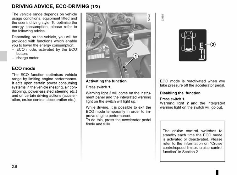
2.6
DRIVING ADVICE, ECO-DRIVING (1/2)The vehicle range depends on vehicle usage conditions, equipment fitted and the user’s driving style. To optimise the energy consumption, please refer to the following advice.Depending on the vehicle, you will be provided with functions which enable you to lower the energy consumption:– ECO mode, activated by the ECO
button;– charge meter.
ECO modeThe ECO function optimises vehicle range by limiting engine performance. It acts upon certain power consuming systems in the vehicle (heating, air con-ditioning, power-assisted steering etc.) and on certain driving actions (acceler-ation, cruise control, deceleration etc.).
Activating the functionPress switch 1.Warning light 2 will come on the instru-ment panel and the integrated warning light on the switch will light up.While driving, it is possible to exit the ECO mode temporarily in order to im-prove engine performance.To do this, press the accelerator pedal firmly and fully.
2
1
ECO mode is reactivated when you take pressure off the accelerator pedal.
Disabling the functionPress switch 1.Warning light 2 and the integrated warning light on the switch will go out.
The cruise control switches to standby each time the ECO mode is activated or deactivated. Please refer to the information on “Cruise control/speed limiter: cruise control function” in Section 2.
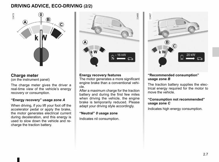
2.7
Energy recovery featuresThe motor generates a more significant engine brake than a conventional vehi-cle.After a maximum charge for the traction battery and during the first few miles when driving the vehicle, the engine brake is temporarily reduced. Please adapt your driving style accordingly.
“Neutral” 0 usage zoneIndicates nil consumption.
Charge meter(on the instrument panel)The charge meter gives the driver a real-time view of the vehicle’s energy recovery or consumption.
“Energy recovery” usage zone AWhen driving, if you lift your foot off the accelerator pedal or apply the brake, the motor generates electrical current during deceleration, and this energy is used to slow down the vehicle and re-charge the traction battery.
A
0B
C
“Recommended consumption” usage zone BThe traction battery supplies the elec-trical energy required for the motor to move the vehicle.
“Consumption not recommended” usage zone CIndicates high energy consumption.
A
DRIVING ADVICE, ECO-DRIVING (2/2)
BC
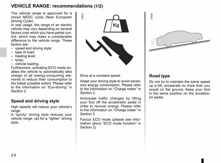
2.8
VEHICLE RANGE: recommendations (1/2)The vehicle range is approved for a mixed NEDC cycle (New European Driving Cycle).In real usage, the range of an electric vehicle may vary depending on several factors over which you have partial con-trol, which may make a considerable difference to the vehicle range. These factors are:– speed and driving style;– type of road;– heating level;– tyres;– vehicle loading.Furthermore, activating ECO mode en-ables the vehicle to automatically take charge of all energy-consuming ele-ments to reduce their consumption to the fullest possible extent. Please refer to the information on “Eco-driving” in Section 2.
Speed and driving styleHigh speeds will reduce your vehicle’s range.A “sporty” driving style reduces your vehicle range: opt for a “lighter” driving style.
Drive at a constant speed.Adapt your driving style to avoid exces-sive energy consumption. Please refer to the information on “Charge meter” in Section 2.Anticipate traffic changes by lifting your foot off the accelerator pedal in order to recover energy. Please refer to the information on “Charge meter” in Section 2.Favour ECO mode (please see infor-mation about “ECO mode function” in Section 2).
Road typeDo not try to maintain the same speed up a hill, accelerate no more than you would on flat ground. Keep your foot in the same position on the accelera-tor pedal.
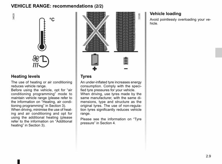
2.9
VEHICLE RANGE: recommendations (2/2)
Heating levelsThe use of heating or air conditioning reduces vehicle range.Before using the vehicle, opt for “air conditioning programming” mode to maintain vehicle range (please refer to the information on “Heating, air condi-tioning programming” in Section 3).When driving, minimise the use of heat-ing and air conditioning and opt for using the additional heating (please refer to the information on “Additional heating” in Section 3).
TyresAn under-inflated tyre increases energy consumption. Comply with the speci-fied tyre pressures for your vehicle.When driving, use tyres made by the same manufacturer, with the same di-mensions, type and structure as the original tyres. The use of non-regula-tion tyres significantly reduces vehicle range.Please see the information on “Tyre pressure” in Section 4.
Vehicle loadingAvoid pointlessly overloading your ve-hicle.
2.10
ENVIRONMENTEmissionsYour vehicle has been designed to emit fewer greenhouse gases (CO2) while in use, and therefore to consume less fuel (eg. 140 g/km, equivalent to 5.3 l/100 km for a diesel vehicle).Our vehicles are also equipped with a particle filter system including a cata-lytic converter, an oxygen sensor and an active carbon filter (the latter pre-vents vapour from the fuel tank being released into the open air).For certain diesel vehicles, this system also has a particle filter to reduce the volume of soot particles emitted.
Please make your own contribution towards protecting the environment too– Worn parts replaced in the course of
routine vehicle maintenance (vehi-cle battery, oil filter, air filter, batter-ies, etc.) and oil containers (empty or filled with used oil) must be disposed of through specialist organisations.
– At the end of the vehicle’s service life, it should be sent to approved centres to ensure that it is recycled.
– In all cases, comply with local legis-lation.
RecyclingYour vehicle is 85% recyclable and 95% recoverable.To achieve these objectives, many of the vehicle components have been de-signed to enable them to be recycled. The materials and structures have been carefully designed to allow these components to be easily removed and reprocessed by specialist companies.In order to preserve raw material re-sources, this vehicle incorporates nu-merous parts made from recycled plas-tics or renewable materials (vegetable or animal-derived materials such as cotton or wool).
Your vehicle has been designed with respect for the environment in mind for its entire service life: during production, use and at the end of its life.This commitment is illustrated by the of the manufacturer eco² signature.
ManufactureYour vehicle has been manufactured at a factory which complies with a policy to reduce the environmental impact on the surrounding areas (reduction of water and energy consumption, visual and noise pollution, atmospheric emis-sions and waste water; sorting and re-using waste).
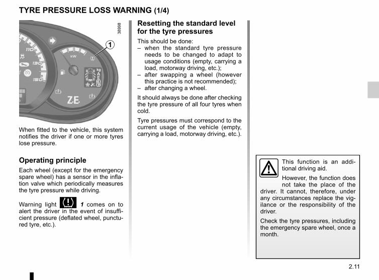
2.11
TYRE PRESSURE LOSS WARNING (1/4)
When fitted to the vehicle, this system notifies the driver if one or more tyres lose pressure.
Operating principleEach wheel (except for the emergency spare wheel) has a sensor in the infla-tion valve which periodically measures the tyre pressure while driving.
Warning light 1 comes on to alert the driver in the event of insuffi-cient pressure (deflated wheel, punctu-red tyre, etc.).
Resetting the standard level for the tyre pressuresThis should be done:– when the standard tyre pressure
needs to be changed to adapt to usage conditions (empty, carrying a load, motorway driving, etc.);
– after swapping a wheel (however this practice is not recommended);
– after changing a wheel.It should always be done after checking the tyre pressure of all four tyres when cold.Tyre pressures must correspond to the current usage of the vehicle (empty, carrying a load, motorway driving, etc.).
This function is an addi-tional driving aid.However, the function does not take the place of the
driver. It cannot, therefore, under any circumstances replace the vig-ilance or the responsibility of the driver.Check the tyre pressures, including the emergency spare wheel, once a month.
1
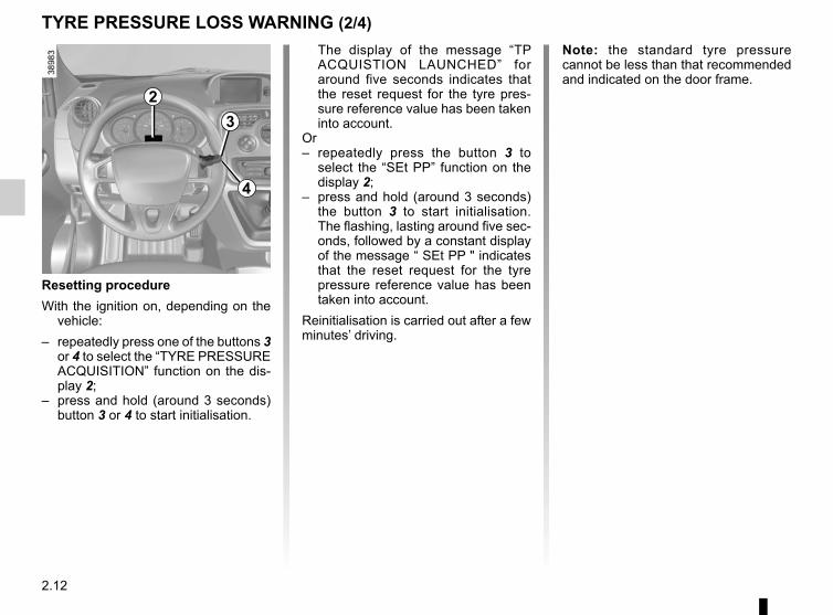
2.12
TYRE PRESSURE LOSS WARNING (2/4)
23
4
The display of the message “TP ACQUISTION LAUNCHED” for around five seconds indicates that the reset request for the tyre pres-sure reference value has been taken into account.
Or– repeatedly press the button 3 to
select the “SEt PP” function on the display 2;
– press and hold (around 3 seconds) the button 3 to start initialisation. The flashing, lasting around five sec-onds, followed by a constant display of the message “ SEt PP " indicates that the reset request for the tyre pressure reference value has been taken into account.
Reinitialisation is carried out after a few minutes’ driving.
Resetting procedureWith the ignition on, depending on the
vehicle:– repeatedly press one of the buttons 3
or 4 to select the “TYRE PRESSURE ACQUISITION” function on the dis-play 2;
– press and hold (around 3 seconds) button 3 or 4 to start initialisation.
Note: the standard tyre pressure cannot be less than that recommended and indicated on the door frame.
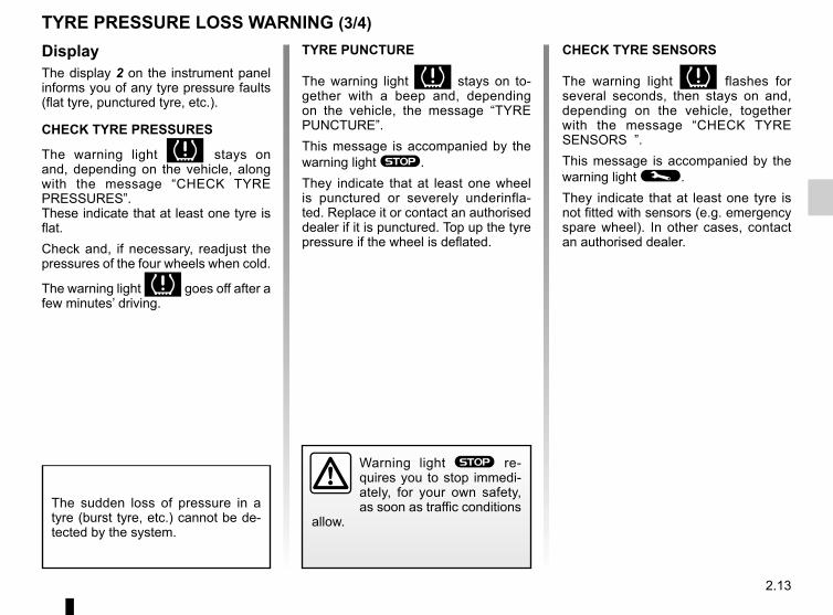
2.13
TYRE PRESSURE LOSS WARNING (3/4)TYRE PUNCTURE
The warning light stays on to-gether with a beep and, depending on the vehicle, the message “TYRE PUNCTURE”.This message is accompanied by the warning light ®.They indicate that at least one wheel is punctured or severely underinfla-ted. Replace it or contact an authorised dealer if it is punctured. Top up the tyre pressure if the wheel is deflated.
Warning light ® re-quires you to stop immedi-ately, for your own safety, as soon as traffic conditions
allow.The sudden loss of pressure in a tyre (burst tyre, etc.) cannot be de-tected by the system.
CHECK TYRE SENSORS
The warning light flashes for several seconds, then stays on and, depending on the vehicle, together with the message “CHECK TYRE SENSORS ”.This message is accompanied by the warning light ©.They indicate that at least one tyre is not fitted with sensors (e.g. emergency spare wheel). In other cases, contact an authorised dealer.
DisplayThe display 2 on the instrument panel informs you of any tyre pressure faults (flat tyre, punctured tyre, etc.).
CHECK TYRE PRESSURES
The warning light stays on and, depending on the vehicle, along with the message “CHECK TYRE PRESSURES”.These indicate that at least one tyre is flat.Check and, if necessary, readjust the pressures of the four wheels when cold.
The warning light goes off after a few minutes’ driving.
2.14
Replacing wheels/tyresThis system requires specific equip-ment (wheels, tyres, hubcaps, etc.). Please see the information on “Tyres” in Section 5.Contact an approved Dealer to fit new tyres and to find out about available ac-cessories compatible with the system and available from your dealer net-work: the use of any other accessory could affect the correct operation of the system or damage a sensor.
Emergency spare wheelIf the vehicle is equipped with an emer-gency spare wheel, it will not have a sensor. When it is fitted on the vehi-
cle, the warning light flashes for several seconds, then stays on, to-gether with the warning light ©. Depending on the vehicle, the message “CHECK TYRE SENSORS” appears on the instrument panel.
Readjustment of tyre pressuresThe tyre pressures must be adjusted when cold (please refer to the label lo-cated on the edge of the driver’s door).If tyre pressures cannot be checked when the tyres are cold, the recom-mended pressures must be increased by 0.2 to 0.3 bar (3 PSI).Never deflate a hot tyre.
TYRE PRESSURE LOSS WARNING (4/4)
Tyre repair product and inflation kitBecause the valves are specially desi-gned, only use equipment approved by the approved network. Please refer to “Tyre inflation kit” in Section 5.
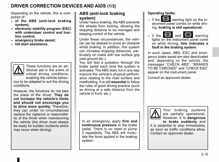
2.15
DRIVER CORRECTION DEVICES AND AIDS (1/3)Depending on the vehicle, this is com-posed of:– of the ABS (anti-lock braking
system);– electronic stability program (ESC)
with understeer control and trac-tion control;
– emergency brake assist;– hill start assistance.
In an emergency, apply firm and continuous pressure to the brake pedal. There is no need to pump it repeatedly. The ABS will modu-late the force applied in the braking system.
These functions are an ad-ditional aid in the event of critical driving conditions, enabling the vehicle behav-
iour to be adapted to suit the driving conditions.However, the functions do not take the place of the driver. They do not increase the vehicle’s limits and should not encourage you to drive more quickly. Therefore, they can under no circumstances replace the vigilance or responsibil-ity of the driver when manoeuvring the vehicle (the driver must always be ready for sudden incidents which may occur when driving).
Your braking systems are partially operational. However, it is dangerous to brake suddenly and
it is essential to stop immediately, as soon as traffic conditions allow. Contact an approved dealer.
ABS (anti-lock braking system)Under heavy braking, the ABS prevents the wheels from locking, allowing the stopping distance to be managed and keeping control of the vehicle.Under these circumstances, the vehi-cle can be steered to avoid an obstacle whilst braking. In addition, this system can increase stopping distances, par-ticularly on roads with low surface grip (wet ground etc.).You will feel a pulsation through the brake pedal each time the system is activated. The ABS does not in any way improve the vehicle’s physical perform-ance relating to the road surface and roadholding. It is still essential to follow the rules of good driving practice (such as driving at a safe distance from the vehicle in front, etc.).
Operating faults:
– if the x warning light on the in-strument panel comes on while driv-ing, braking is still operational;
– if the x and D warning lights on the instrument panel come on while driving, this indicates a fault in the braking system.
In such cases, ABS, ESC and emer-gency brake assist are also deactivated and, depending on the vehicle, the messages “CHECK ABS”, “BRAKES TO BE CHECKED” and “CHECK ESC” appear on the instrument panel.Consult an approved dealer.
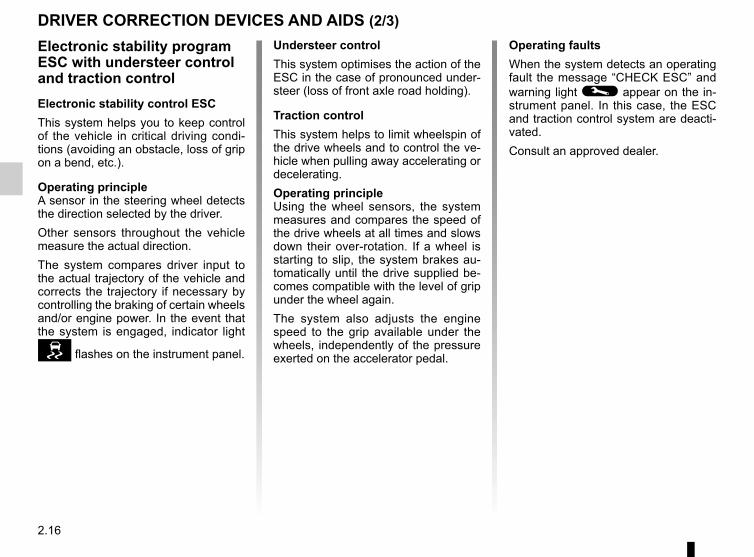
2.16
DRIVER CORRECTION DEVICES AND AIDS (2/3)
Electronic stability program ESC with understeer control and traction controlElectronic stability control ESCThis system helps you to keep control of the vehicle in critical driving condi-tions (avoiding an obstacle, loss of grip on a bend, etc.).
Operating principleA sensor in the steering wheel detects the direction selected by the driver.Other sensors throughout the vehicle measure the actual direction.The system compares driver input to the actual trajectory of the vehicle and corrects the trajectory if necessary by controlling the braking of certain wheels and/or engine power. In the event that the system is engaged, indicator light
flashes on the instrument panel.
Understeer controlThis system optimises the action of the ESC in the case of pronounced under-steer (loss of front axle road holding).
Traction controlThis system helps to limit wheelspin of the drive wheels and to control the ve-hicle when pulling away accelerating or decelerating.Operating principleUsing the wheel sensors, the system measures and compares the speed of the drive wheels at all times and slows down their over-rotation. If a wheel is starting to slip, the system brakes au-tomatically until the drive supplied be-comes compatible with the level of grip under the wheel again.The system also adjusts the engine speed to the grip available under the wheels, independently of the pressure exerted on the accelerator pedal.
Operating faultsWhen the system detects an operating fault the message “CHECK ESC” and warning light © appear on the in-strument panel. In this case, the ESC and traction control system are deacti-vated.Consult an approved dealer.
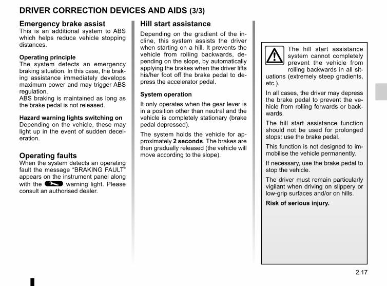
2.17
Emergency brake assistThis is an additional system to ABS which helps reduce vehicle stopping distances.
Operating principleThe system detects an emergency braking situation. In this case, the brak-ing assistance immediately develops maximum power and may trigger ABS regulation.ABS braking is maintained as long as the brake pedal is not released.
Hazard warning lights switching onDepending on the vehicle, these may light up in the event of sudden decel-eration.
Operating faultsWhen the system detects an operating fault the message “BRAKING FAULT” appears on the instrument panel along with the © warning light. Please consult an authorised dealer.
DRIVER CORRECTION DEVICES AND AIDS (3/3)
Hill start assistanceDepending on the gradient of the in-cline, this system assists the driver when starting on a hill. It prevents the vehicle from rolling backwards, de-pending on the slope, by automatically applying the brakes when the driver lifts his/her foot off the brake pedal to de-press the accelerator pedal.
System operationIt only operates when the gear lever is in a position other than neutral and the vehicle is completely stationary (brake pedal depressed).The system holds the vehicle for ap-proximately 2 seconds. The brakes are then gradually released (the vehicle will move according to the slope).
The hill start assistance system cannot completely prevent the vehicle from rolling backwards in all sit-
uations (extremely steep gradients, etc.).In all cases, the driver may depress the brake pedal to prevent the ve-hicle from rolling forwards or back-wards.The hill start assistance function should not be used for prolonged stops: use the brake pedal.This function is not designed to im-mobilise the vehicle permanently.If necessary, use the brake pedal to stop the vehicle.The driver must remain particularly vigilant when driving on slippery or low-grip surfaces and/or on hills.Risk of serious injury.
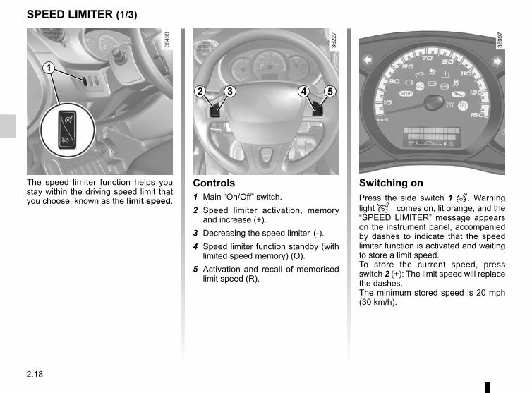
2.18
The speed limiter function helps you stay within the driving speed limit that you choose, known as the limit speed.
SPEED LIMITER (1/3)
Switching onPress the side switch 1 . Warning light comes on, lit orange, and the “SPEED LIMITER” message appears on the instrument panel, accompanied by dashes to indicate that the speed limiter function is activated and waiting to store a limit speed.To store the current speed, press switch 2 (+): The limit speed will replace the dashes.The minimum stored speed is 20 mph (30 km/h).
Controls1 Main “On/Off” switch.2 Speed limiter activation, memory
and increase (+).3 Decreasing the speed limiter (-).4 Speed limiter function standby (with
limited speed memory) (O).5 Activation and recall of memorised
limit speed (R).
1
2 4 53

2.19
SPEED LIMITER (2/3)
Exceeding the limit speedIt is possible to exceed the limit speed at any moment. To do this: press the accelerator pedal firmly and fully (beyond the resistance point).Whilst the speed is being exceeded, the cruising speed displayed on the in-strument panel flashes.Then, release the accelerator: the speed limiter function will return as soon as you reach a speed lower than the stored speed.
Limited speed cannot be maintainedIf driving up or down a steep gradient, the system is unable to maintain the limit speed: the stored speed will flash on the instrument panel information dis-play to inform you of this situation.
The speed limiter function is in no way linked to the brak-ing system.
DrivingWhen a limited speed has been stored and this speed is not reached, driving is similar to driving a vehicle without the speed limiter function.Once you have reached the stored speed, no effort on the accelera-tor pedal will allow you to exceed the programmed speed except in an emergency (refer to information on “Exceeding the limit speed”).
Varying the limit speedThe limit speed may be changed by re-peatedly pressing:– switch 2 (+) to increase the speed;– switch 3 (-) to decrease the speed.
2 4 53
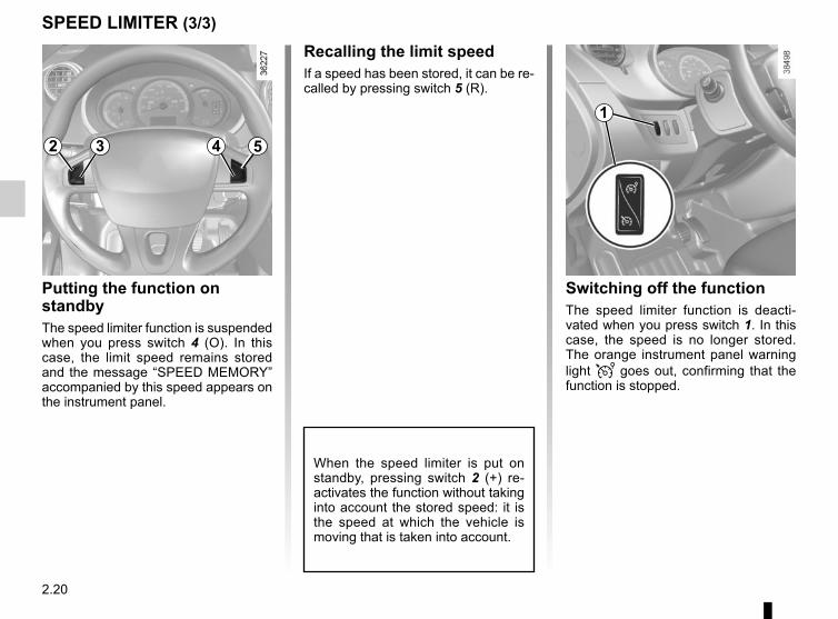
2.20
SPEED LIMITER (3/3)
Putting the function on standbyThe speed limiter function is suspended when you press switch 4 (O). In this case, the limit speed remains stored and the message “SPEED MEMORY” accompanied by this speed appears on the instrument panel.
Recalling the limit speedIf a speed has been stored, it can be re-called by pressing switch 5 (R).
When the speed limiter is put on standby, pressing switch 2 (+) re-activates the function without taking into account the stored speed: it is the speed at which the vehicle is moving that is taken into account.
Switching off the functionThe speed limiter function is deacti-vated when you press switch 1. In this case, the speed is no longer stored. The orange instrument panel warning light goes out, confirming that the function is stopped.
1
2 4 53
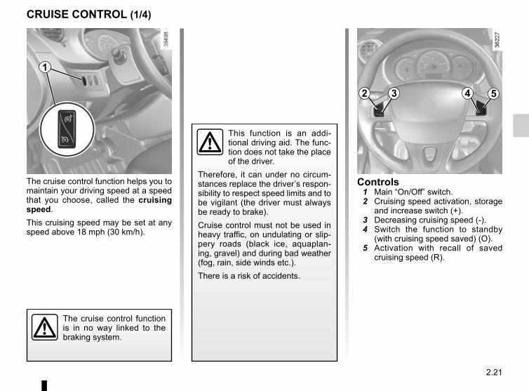
2.21
The cruise control function helps you to maintain your driving speed at a speed that you choose, called the cruising speed.This cruising speed may be set at any speed above 18 mph (30 km/h).
CRUISE CONTROL (1/4)
The cruise control function is in no way linked to the braking system.
This function is an addi-tional driving aid. The func-tion does not take the place of the driver.
Therefore, it can under no circum-stances replace the driver’s respon-sibility to respect speed limits and to be vigilant (the driver must always be ready to brake).Cruise control must not be used in heavy traffic, on undulating or slip-pery roads (black ice, aquaplan-ing, gravel) and during bad weather (fog, rain, side winds etc.).There is a risk of accidents.
Controls 1 Main “On/Off” switch. 2 Cruising speed activation, storage
and increase switch (+). 3 Decreasing cruising speed (-). 4 Switch the function to standby
(with cruising speed saved) (O). 5 Activation with recall of saved
cruising speed (R).
1
2 4 53
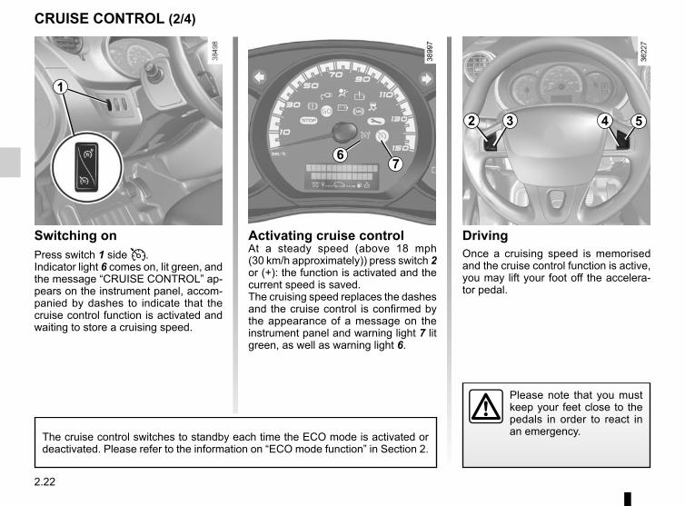
2.22
DrivingOnce a cruising speed is memorised and the cruise control function is active, you may lift your foot off the accelera-tor pedal.
Switching onPress switch 1 side .Indicator light 6 comes on, lit green, and the message “CRUISE CONTROL” ap-pears on the instrument panel, accom-panied by dashes to indicate that the cruise control function is activated and waiting to store a cruising speed.
Please note that you must keep your feet close to the pedals in order to react in an emergency.
CRUISE CONTROL (2/4)
67
Activating cruise controlAt a steady speed (above 18 mph (30 km/h approximately)) press switch 2 or (+): the function is activated and the current speed is saved.The cruising speed replaces the dashes and the cruise control is confirmed by the appearance of a message on the instrument panel and warning light 7 lit green, as well as warning light 6.
1
The cruise control switches to standby each time the ECO mode is activated or deactivated. Please refer to the information on “ECO mode function” in Section 2.
2 4 53
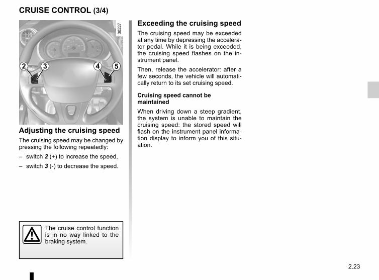
2.23
CRUISE CONTROL (3/4)
Exceeding the cruising speedThe cruising speed may be exceeded at any time by depressing the accelera-tor pedal. While it is being exceeded, the cruising speed flashes on the in-strument panel.Then, release the accelerator: after a few seconds, the vehicle will automati-cally return to its set cruising speed.
Cruising speed cannot be maintainedWhen driving down a steep gradient, the system is unable to maintain the cruising speed: the stored speed will flash on the instrument panel informa-tion display to inform you of this situ-ation.
Adjusting the cruising speedThe cruising speed may be changed by pressing the following repeatedly:– switch 2 (+) to increase the speed,– switch 3 (-) to decrease the speed.
The cruise control function is in no way linked to the braking system.
2 4 53
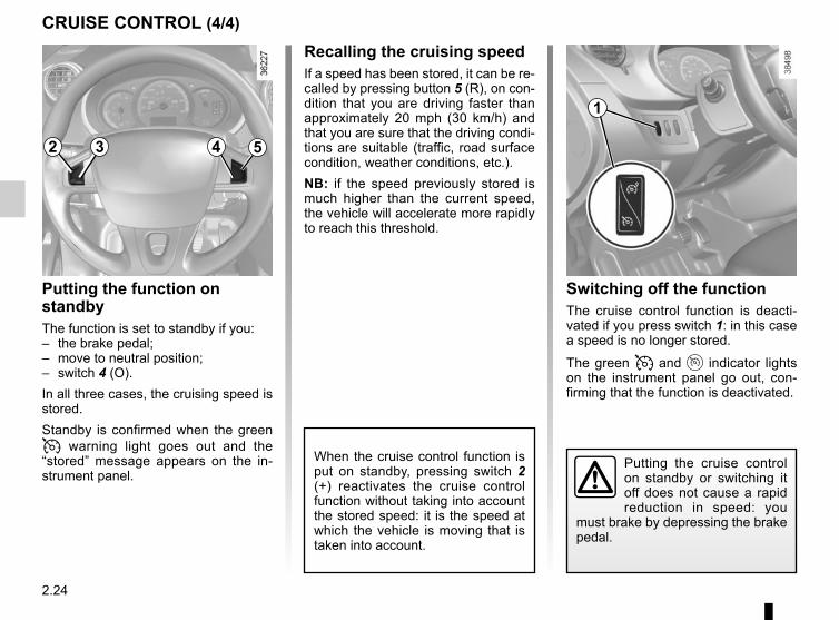
2.24
Switching off the functionThe cruise control function is deacti-vated if you press switch 1: in this case a speed is no longer stored.
The green and indicator lights on the instrument panel go out, con-firming that the function is deactivated.
Recalling the cruising speedIf a speed has been stored, it can be re-called by pressing button 5 (R), on con-dition that you are driving faster than approximately 20 mph (30 km/h) and that you are sure that the driving condi-tions are suitable (traffic, road surface condition, weather conditions, etc.).NB: if the speed previously stored is much higher than the current speed, the vehicle will accelerate more rapidly to reach this threshold.
When the cruise control function is put on standby, pressing switch 2 (+) reactivates the cruise control function without taking into account the stored speed: it is the speed at which the vehicle is moving that is taken into account.
Putting the function on standbyThe function is set to standby if you:– the brake pedal;– move to neutral position;– switch 4 (O).In all three cases, the cruising speed is stored.Standby is confirmed when the green warning light goes out and the “stored” message appears on the in-strument panel.
CRUISE CONTROL (4/4)
Putting the cruise control on standby or switching it off does not cause a rapid reduction in speed: you
must brake by depressing the brake pedal.
1
2 4 53
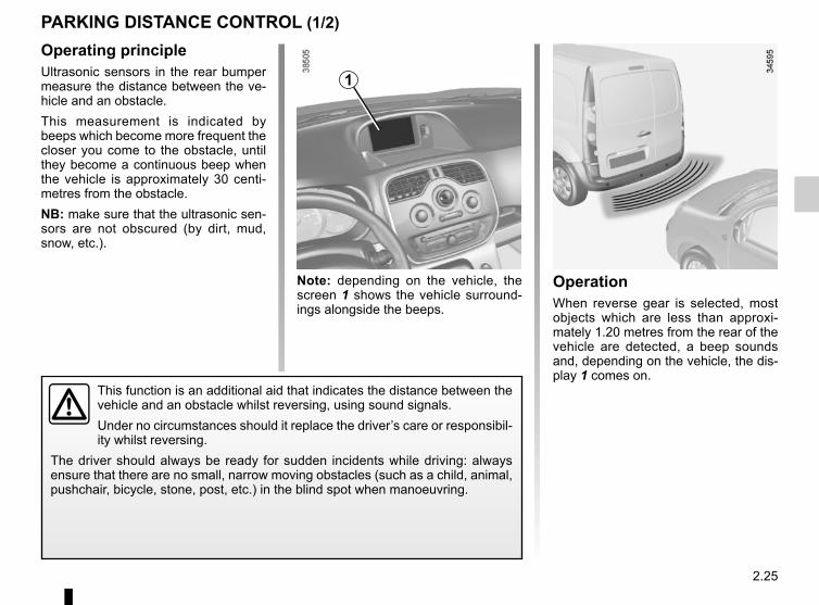
2.25
Operating principleUltrasonic sensors in the rear bumper measure the distance between the ve-hicle and an obstacle.This measurement is indicated by beeps which become more frequent the closer you come to the obstacle, until they become a continuous beep when the vehicle is approximately 30 centi-metres from the obstacle.NB: make sure that the ultrasonic sen-sors are not obscured (by dirt, mud, snow, etc.).
PARKING DISTANCE CONTROL (1/2)
OperationWhen reverse gear is selected, most objects which are less than approxi-mately 1.20 metres from the rear of the vehicle are detected, a beep sounds and, depending on the vehicle, the dis-play 1 comes on.
Note: depending on the vehicle, the screen 1 shows the vehicle surround-ings alongside the beeps.
This function is an additional aid that indicates the distance between the vehicle and an obstacle whilst reversing, using sound signals.Under no circumstances should it replace the driver’s care or responsibil-ity whilst reversing.
The driver should always be ready for sudden incidents while driving: always ensure that there are no small, narrow moving obstacles (such as a child, animal, pushchair, bicycle, stone, post, etc.) in the blind spot when manoeuvring.
1
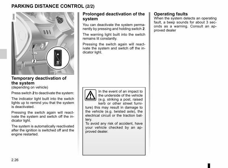
2.26
Temporary deactivation of the system(depending on vehicle)Press switch 2 to deactivate the system:The indicator light built into the switch lights up to remind you that the system is deactivated.Pressing the switch again will react-ivate the system and switch off the in-dicator light.The system is automatically reactivated after the ignition is switched off and the engine restarted.
PARKING DISTANCE CONTROL (2/2)
Operating faultsWhen the system detects an operating fault, a beep sounds for about 3 sec-onds as a warning. Consult an ap-proved dealer
In the event of an impact to the underside of the vehicle (e.g. striking a post, raised kerb or other street furni-
ture) this may result in damage to the vehicle (e.g. twisted axle), the electrical circuit or the traction bat-tery.To avoid any risk of accident, have your vehicle checked by an ap-proved dealer.
2
Prolonged deactivation of the systemYou can deactivate the system perma-nently by pressing and holding switch 2.The warning light built into the switch remains lit constantly.Pressing the switch again will react-ivate the system and switch off the in-dicator light.
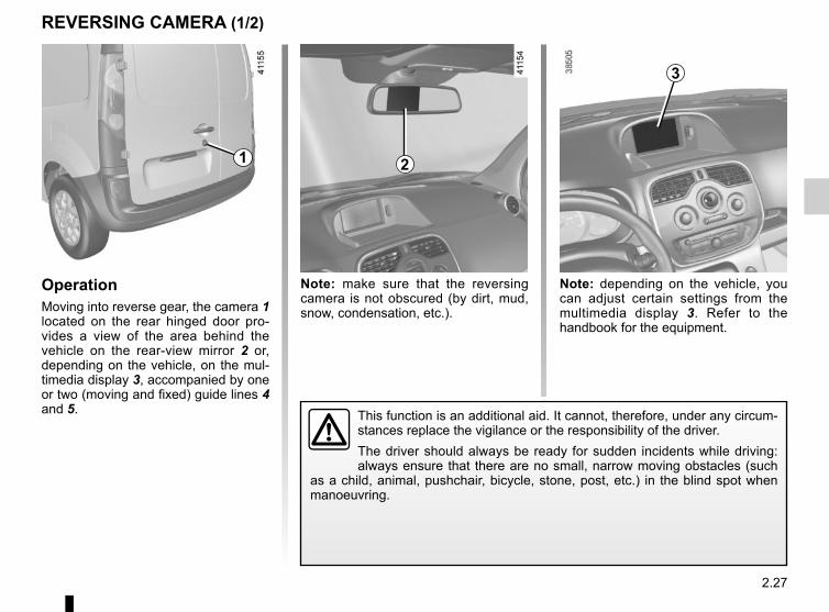
2.27
REVERSING CAMERA (1/2)
OperationMoving into reverse gear, the camera 1 located on the rear hinged door pro-vides a view of the area behind the vehicle on the rear-view mirror 2 or, depending on the vehicle, on the mul-timedia display 3, accompanied by one or two (moving and fixed) guide lines 4 and 5.
Note: make sure that the reversing camera is not obscured (by dirt, mud, snow, condensation, etc.).
Note: depending on the vehicle, you can adjust certain settings from the multimedia display 3. Refer to the handbook for the equipment.
This function is an additional aid. It cannot, therefore, under any circum-stances replace the vigilance or the responsibility of the driver.The driver should always be ready for sudden incidents while driving: always ensure that there are no small, narrow moving obstacles (such
as a child, animal, pushchair, bicycle, stone, post, etc.) in the blind spot when manoeuvring.
2
3
1
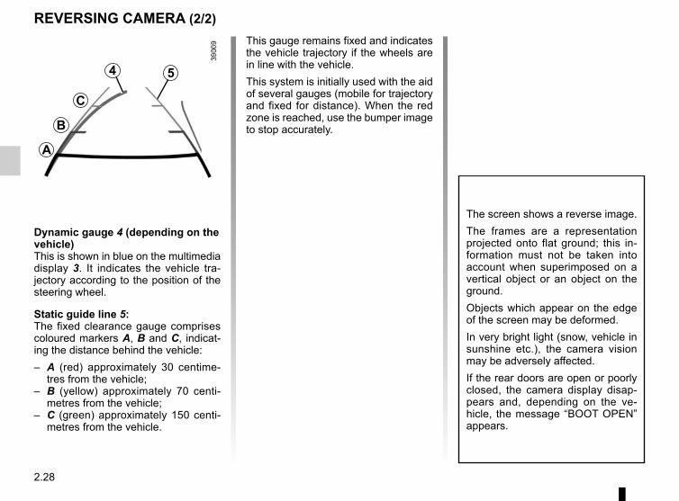
2.28
REVERSING CAMERA (2/2)
The screen shows a reverse image.The frames are a representation projected onto flat ground; this in-formation must not be taken into account when superimposed on a vertical object or an object on the ground.Objects which appear on the edge of the screen may be deformed.In very bright light (snow, vehicle in sunshine etc.), the camera vision may be adversely affected.If the rear doors are open or poorly closed, the camera display disap-pears and, depending on the ve-hicle, the message “BOOT OPEN” appears.
Dynamic gauge 4 (depending on the vehicle)This is shown in blue on the multimedia display 3. It indicates the vehicle tra-jectory according to the position of the steering wheel.
Static guide line 5:The fixed clearance gauge comprises coloured markers A, B and C, indicat-ing the distance behind the vehicle:– A (red) approximately 30 centime-
tres from the vehicle;– B (yellow) approximately 70 centi-
metres from the vehicle;– C (green) approximately 150 centi-
metres from the vehicle.
This gauge remains fixed and indicates the vehicle trajectory if the wheels are in line with the vehicle.This system is initially used with the aid of several gauges (mobile for trajectory and fixed for distance). When the red zone is reached, use the bumper image to stop accurately.
4
C
B
A
5
3.1
Section 3: Your comfort
Air vents: air outlets . . . . . . . . . . . . . . . . . . . . . . . . . . . . . . . . . . . . . . . . . . . . . . . . . . . . . . . . . . . . . . 3.2Heating, air-conditioning . . . . . . . . . . . . . . . . . . . . . . . . . . . . . . . . . . . . . . . . . . . . . . . . . . . . . . . . . . 3.4
programming . . . . . . . . . . . . . . . . . . . . . . . . . . . . . . . . . . . . . . . . . . . . . . . . . . . . . . . . . . . . . 3.8Additional heating . . . . . . . . . . . . . . . . . . . . . . . . . . . . . . . . . . . . . . . . . . . . . . . . . . . . . . . . . . . . . . . 3.10Air conditioning: information and advice on use . . . . . . . . . . . . . . . . . . . . . . . . . . . . . . . . . . . . . . . . 3.12Multimedia equipment . . . . . . . . . . . . . . . . . . . . . . . . . . . . . . . . . . . . . . . . . . . . . . . . . . . . . . . . . . . . 3.14Interior lighting . . . . . . . . . . . . . . . . . . . . . . . . . . . . . . . . . . . . . . . . . . . . . . . . . . . . . . . . . . . . . . . . . . 3.15Sun visor/Mirror . . . . . . . . . . . . . . . . . . . . . . . . . . . . . . . . . . . . . . . . . . . . . . . . . . . . . . . . . . . . . . . . . 3.16Electric windows . . . . . . . . . . . . . . . . . . . . . . . . . . . . . . . . . . . . . . . . . . . . . . . . . . . . . . . . . . . . . . . . 3.17Ashtrays, Cigarette lighter, Accessories socket . . . . . . . . . . . . . . . . . . . . . . . . . . . . . . . . . . . . . . . . . 3.18Passenger compartment storage/fittings . . . . . . . . . . . . . . . . . . . . . . . . . . . . . . . . . . . . . . . . . . . . . . 3.19Rear bench seat . . . . . . . . . . . . . . . . . . . . . . . . . . . . . . . . . . . . . . . . . . . . . . . . . . . . . . . . . . . . . . . . 3.23Transporting objects . . . . . . . . . . . . . . . . . . . . . . . . . . . . . . . . . . . . . . . . . . . . . . . . . . . . . . . . . . . . . 3.25
in the boot . . . . . . . . . . . . . . . . . . . . . . . . . . . . . . . . . . . . . . . . . . . . . . . . . . . . . . . . . . . . . . . 3.25Towbar . . . . . . . . . . . . . . . . . . . . . . . . . . . . . . . . . . . . . . . . . . . . . . . . . . . . . . . . . . . . . . . . . . 3.26
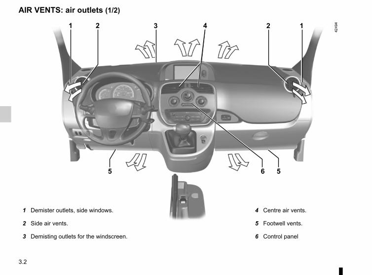
3.2
AIR VENTS: air outlets (1/2)
1 3 4 12
5 56
2
1 Demister outlets, side windows.
2 Side air vents.
3 Demisting outlets for the windscreen.
4 Centre air vents.
5 Footwell vents.
6 Control panel
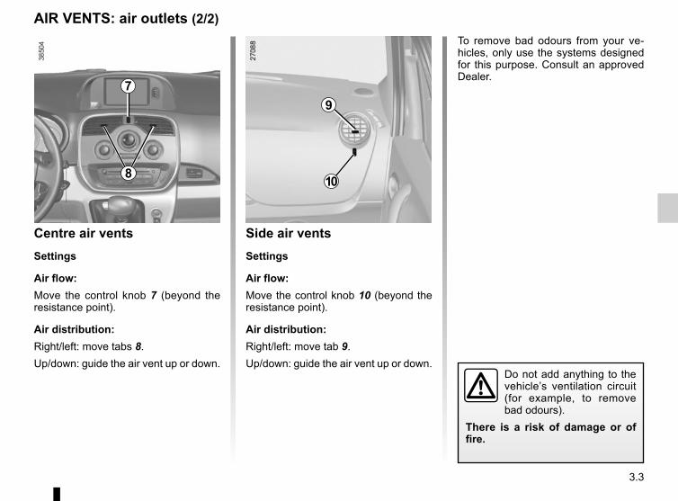
3.3
Centre air ventsSettings
Air flow:Move the control knob 7 (beyond the resistance point).
Air distribution:Right/left: move tabs 8.Up/down: guide the air vent up or down.
AIR VENTS: air outlets (2/2)
9
10
7
8
Side air ventsSettings
Air flow:Move the control knob 10 (beyond the resistance point).
Air distribution:Right/left: move tab 9.Up/down: guide the air vent up or down.
Do not add anything to the vehicle’s ventilation circuit (for example, to remove bad odours).
There is a risk of damage or of fire.
To remove bad odours from your ve-hicles, only use the systems designed for this purpose. Consult an approved Dealer.
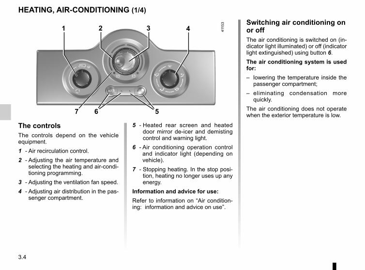
3.4
Switching air conditioning on or offThe air conditioning is switched on (in-dicator light illuminated) or off (indicator light extinguished) using button 6.The air conditioning system is used for:– lowering the temperature inside the
passenger compartment;– eliminating condensation more
quickly.The air conditioning does not operate when the exterior temperature is low.
5 - Heated rear screen and heated door mirror de-icer and demisting control and warning light.
6 - Air conditioning operation control and indicator light (depending on vehicle).
7 - Stopping heating. In the stop posi-tion, heating no longer uses up any energy.
Information and advice for use:Refer to information on “Air condition-ing: information and advice on use”.
The controlsThe controls depend on the vehicle equipment.1 - Air recirculation control.2 - Adjusting the air temperature and
selecting the heating and air-condi-tioning programming.
3 - Adjusting the ventilation fan speed.4 - Adjusting air distribution in the pas-
senger compartment.
HEATING, AIR-CONDITIONING (1/4)
1 42 3
6 57
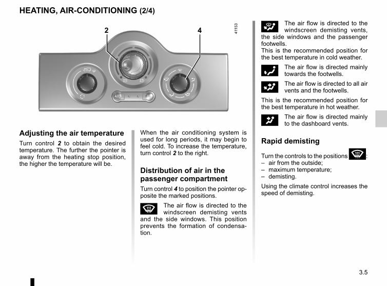
3.5
i The air flow is directed to the windscreen demisting vents,
the side windows and the passenger footwells.This is the recommended position for the best temperature in cold weather.
ó The air flow is directed mainly towards the footwells.
G The air flow is directed to all air vents and the footwells.
This is the recommended position for the best temperature in hot weather.
J The air flow is directed mainly to the dashboard vents.
Rapid demisting
Turn the controls to the positions W:– air from the outside;– maximum temperature;– demisting.Using the climate control increases the speed of demisting.
Adjusting the air temperatureTurn control 2 to obtain the desired temperature. The further the pointer is away from the heating stop position, the higher the temperature will be.
HEATING, AIR-CONDITIONING (2/4)
When the air conditioning system is used for long periods, it may begin to feel cold. To increase the temperature, turn control 2 to the right.
Distribution of air in the passenger compartmentTurn control 4 to position the pointer op-posite the marked positions.
W The air flow is directed to the windscreen demisting vents
and the side windows. This position prevents the formation of condensa-tion.
2 4
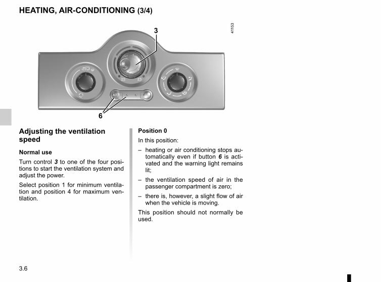
3.6
Adjusting the ventilation speedNormal useTurn control 3 to one of the four posi-tions to start the ventilation system and adjust the power.Select position 1 for minimum ventila-tion and position 4 for maximum ven-tilation.
HEATING, AIR-CONDITIONING (3/4)
3
6
Position 0In this position:– heating or air conditioning stops au-
tomatically even if button 6 is acti-vated and the warning light remains lit;
– the ventilation speed of air in the passenger compartment is zero;
– there is, however, a slight flow of air when the vehicle is moving.
This position should not normally be used.
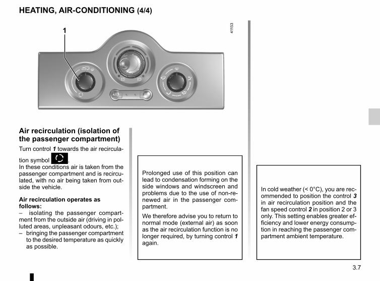
3.7
HEATING, AIR-CONDITIONING (4/4)
Air recirculation (isolation of the passenger compartment)Turn control 1 towards the air recircula-
tion symbol K.In these conditions air is taken from the passenger compartment and is recircu-lated, with no air being taken from out-side the vehicle.
Air recirculation operates as follows:– isolating the passenger compart-ment from the outside air (driving in pol-luted areas, unpleasant odours, etc.);– bringing the passenger compartment
to the desired temperature as quickly as possible.
Prolonged use of this position can lead to condensation forming on the side windows and windscreen and problems due to the use of non-re-newed air in the passenger com-partment.We therefore advise you to return to normal mode (external air) as soon as the air recirculation function is no longer required, by turning control 1 again.
1
In cold weather (< 0°C), you are rec-ommended to position the control 3 in air recirculation position and the fan speed control 2 in position 2 or 3 only. This setting enables greater ef-ficiency and lower energy consump-tion in reaching the passenger com-partment ambient temperature.
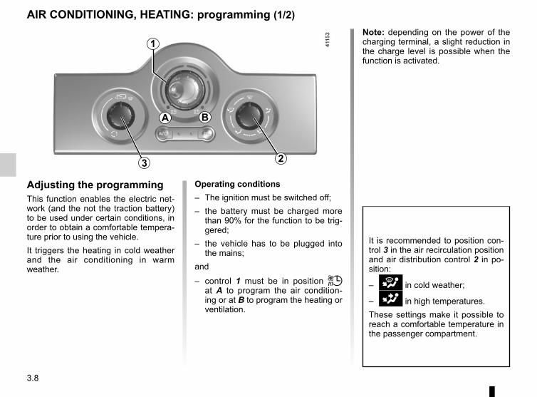
3.8
AIR CONDITIONING, HEATING: programming (1/2)
Adjusting the programmingThis function enables the electric net-work (and the not the traction battery) to be used under certain conditions, in order to obtain a comfortable tempera-ture prior to using the vehicle.It triggers the heating in cold weather and the air conditioning in warm weather.
1
Operating conditions– The ignition must be switched off;– the battery must be charged more
than 90% for the function to be trig-gered;
– the vehicle has to be plugged into the mains;
and
– control 1 must be in position ṗ at A to program the air condition-ing or at B to program the heating or ventilation.
3
It is recommended to position con-trol 3 in the air recirculation position and air distribution control 2 in po-sition:
– i in cold weather;
– G in high temperatures.These settings make it possible to reach a comfortable temperature in the passenger compartment.
A B
2
Note: depending on the power of the charging terminal, a slight reduction in the charge level is possible when the function is activated.
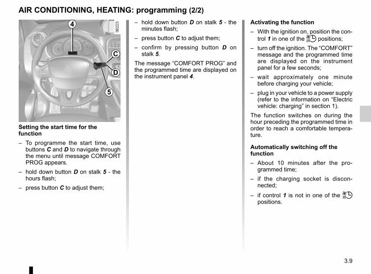
3.9
AIR CONDITIONING, HEATING: programming (2/2)Activating the function– With the ignition on, position the con-
trol 1 in one of the ṗ positions;– turn off the ignition. The “COMFORT”
message and the programmed time are displayed on the instrument panel for a few seconds;
– wait approximately one minute before charging your vehicle;
– plug in your vehicle to a power supply (refer to the information on “Electric vehicle: charging” in section 1).
The function switches on during the hour preceding the programmed time in order to reach a comfortable tempera-ture.
Automatically switching off the function– About 10 minutes after the pro-
grammed time;– if the charging socket is discon-
nected;
– if control 1 is not in one of the ṗ positions.
4
5
C
D
Setting the start time for the function– To programme the start time, use
buttons C and D to navigate through the menu until message COMFORT PROG appears.
– hold down button D on stalk 5 - the hours flash;
– press button C to adjust them;
– hold down button D on stalk 5 - the minutes flash;
– press button C to adjust them;– confirm by pressing button D on
stalk 5.The message “COMFORT PROG” and the programmed time are displayed on the instrument panel 4.
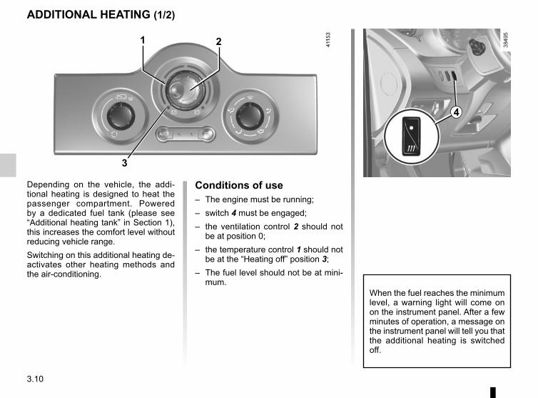
3.10
Conditions of use– The engine must be running;– switch 4 must be engaged;– the ventilation control 2 should not
be at position 0;– the temperature control 1 should not
be at the “Heating off” position 3;– The fuel level should not be at mini-
mum.
ADDITIONAL HEATING (1/2)
Depending on the vehicle, the addi-tional heating is designed to heat the passenger compartment. Powered by a dedicated fuel tank (please see “Additional heating tank” in Section 1), this increases the comfort level without reducing vehicle range.Switching on this additional heating de-activates other heating methods and the air-conditioning.
2
When the fuel reaches the minimum level, a warning light will come on on the instrument panel. After a few minutes of operation, a message on the instrument panel will tell you that the additional heating is switched off.
3
1
4
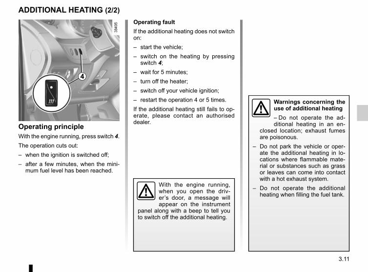
3.11
ADDITIONAL HEATING (2/2)Operating faultIf the additional heating does not switch on:– start the vehicle;– switch on the heating by pressing
switch 4;– wait for 5 minutes;– turn off the heater;– switch off your vehicle ignition;– restart the operation 4 or 5 times.If the additional heating still fails to op-erate, please contact an authorised dealer.Operating principle
With the engine running, press switch 4.The operation cuts out:– when the ignition is switched off;– after a few minutes, when the mini-
mum fuel level has been reached.
With the engine running, when you open the driv-er’s door, a message will appear on the instrument
panel along with a beep to tell you to switch off the additional heating.
Warnings concerning the use of additional heating– Do not operate the ad-ditional heating in an en-
closed location; exhaust fumes are poisonous.
– Do not park the vehicle or oper-ate the additional heating in lo-cations where flammable mate-rial or substances such as grass or leaves can come into contact with a hot exhaust system.
– Do not operate the additional heating when filling the fuel tank.
4
3.12
AIR CONDITIONING: information and operating instructions (1/2)
Do not open the refriger-ant fluid circuit. The fluid may damage eyes or skin.
Operating faultsAs a general rule, contact your ap-proved Dealer in the event of an oper-ating fault.– Reduction in de-icing, demisting
or air conditioning performance. This may be caused by the passen-ger compartment filter cartridge be-coming clogged.
– No cold air is being produced. Check that the controls are set cor-rectly and that the fuses are sound. Otherwise, switch off the system.
RangeIt is normal to notice an increase in energy usage when the air conditioning is operating.Switch off the system when it is not re-quired.Advice for reducing consumption and helping to preserve the environ-mentDrive with the air vents on and the win-dows closed.If the vehicle has been parked in the sun, open the doors for a few moments to let the hot air escape before starting the engine.
MaintenanceRefer to the Maintenance Document for your vehicle for the inspection fre-quency.
Below approximately 10°C, with the engine off it is normal to notice cold air enter the passenger compart-ment via the vents when ventilation has not stopped (refer to the infor-mation on “Heating, air condition-ing” in section 3). It is recommended to position the ventilation control at 0 in case of brief stops.
Presence of water under the vehicle.After prolonged use of the air condi-tioning system, it is normal for water to be present under the vehicle. This is caused by condensation.
NoiseEach time the ignition is switched off, the ventilation will be switched off after about ten seconds.
Vehicles equipped with mode ECOOnce activated, ECO mode may reduce air conditioning perform-ance. Please refer to the informa-tion on “Driving advice, Eco-driving” in Section 2.
Use the air conditioning system reg-ularly, even in cold weather, running it at least once a month for approxi-mately 5 minutes.
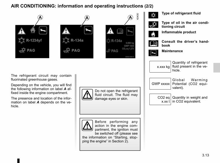
3.13
AIR CONDITIONING: information and operating instructions (2/2)
The refrigerant circuit may contain fluorinated greenhouse gases.Depending on the vehicle, you will find the following information on label A af-fixed inside the engine compartment.The presence and location of the infor-mation on label A depends on the ve-hicle.
A A A
Do not open the refrigerant fluid circuit. The fluid may damage eyes or skin.
Ñ Type of refrigerant fluid
Type of oil in the air condi-tioning circuit
Inflammable product
Consult the driver’s hand-book
Maintenance
Quantity of refrigerant fluid present in the ve-hicle.
x.xxx kg
Globa l Warming Potential (CO2 equi-valent).
GWP xxxxx
Quantity in weight and in CO2 equivalent.
CO2 eq x.xx t
Before performing any action in the engine com-partment, the ignition must be switched off (please see
the information on “Starting, stop-ping the engine” in Section 2).
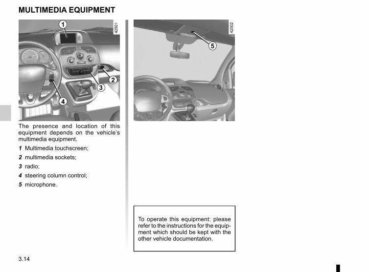
3.14
MULTIMEDIA EQUIPMENT
The presence and location of this equipment depends on the vehicle’s multimedia equipment.1 Multimedia touchscreen;2 multimedia sockets;3 radio;4 steering column control;5 microphone.
To operate this equipment: please refer to the instructions for the equip-ment which should be kept with the other vehicle documentation.
1
32
4
5
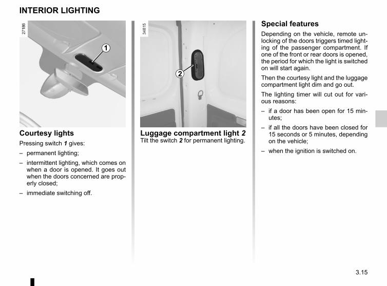
3.15
Luggage compartment light 2Tilt the switch 2 for permanent lighting.
INTERIOR LIGHTING
1
Courtesy lightsPressing switch 1 gives:– permanent lighting;– intermittent lighting, which comes on
when a door is opened. It goes out when the doors concerned are prop-erly closed;
– immediate switching off.
2
Special featuresDepending on the vehicle, remote un-locking of the doors triggers timed light-ing of the passenger compartment. If one of the front or rear doors is opened, the period for which the light is switched on will start again.Then the courtesy light and the luggage compartment light dim and go out.The lighting timer will cut out for vari-ous reasons:– if a door has been open for 15 min-
utes;– if all the doors have been closed for
15 seconds or 5 minutes, depending on the vehicle;
– when the ignition is switched on.
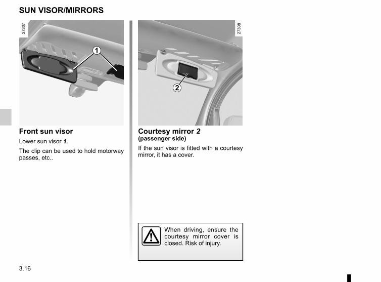
3.16
Front sun visorLower sun visor 1.The clip can be used to hold motorway passes, etc..
SUN VISOR/MIRRORS
Courtesy mirror 2(passenger side)If the sun visor is fitted with a courtesy mirror, it has a cover.
When driving, ensure the courtesy mirror cover is closed. Risk of injury.
2
1
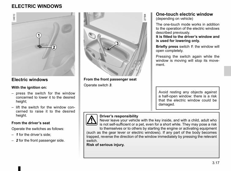
3.17
Electric windowsWith the ignition on:– press the switch for the window
concerned to lower it to the desired height;
– lift the switch for the window con-cerned to raise it to the desired height.
From the driver’s seatOperate the switches as follows:– 1 for the driver’s side;– 2 for the front passenger side.
ELECTRIC WINDOWS
From the front passenger seatOperate switch 3.
1
23
Driver’s responsibilityNever leave your vehicle with the key inside, and with a child, adult who is not self-sufficient or a pet, even for a short while. They may pose a risk to themselves or to others by starting the engine or activating equipment
(such as the gear lever or electric windows). If any part of the body becomes trapped, reverse the direction of the window immediately by pressing the relevant switch.Risk of serious injury.
One-touch electric window(depending on vehicle)The one-touch mode works in addition to the operation of the electric windows described previously.It is fitted to the driver’s window and is used for lowering only.Briefly press switch 1: the window will open completely.Pressing the switch again while the window is moving will stop its move-ment.
Avoid resting any objects against a half-open window: there is a risk that the electric window could be damaged.
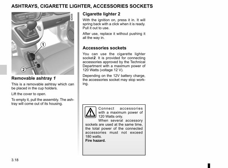
3.18
Removable ashtray 1This is a removable ashtray which can be placed in the cup holders.Lift the cover to open.To empty it, pull the assembly. The ash-tray will come out of its housing.
ASHTRAYS, CIGARETTE LIGHTER, ACCESSORIES SOCKETS
1
Cigarette lighter 2With the ignition on, press it in. It will spring back with a click when it is ready. Pull it out to use.After use, replace it without pushing it all the way in.
Accessories socketsYou can use the cigarette lighter socket2. It is provided for connecting accessories approved by the Technical Department with a maximum power of 120 Watts (voltage 12 V).Depending on the 12V battery charge, the accessories socket may stop work-ing.
2
Connect accessor ies with a maximum power of 120 Watts only.When several accessory
sockets are used at the same time, the total power of the connected accessories must not exceed 180 watts.Fire hazard.
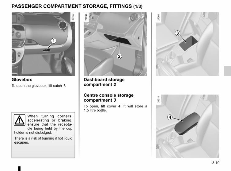
3.19
Dashboard storage compartment 2
Centre console storage compartment 3To open, lift cover 4. It will store a 1.5 litre bottle.
GloveboxTo open the glovebox, lift catch 1.
PASSENGER COMPARTMENT STORAGE, FITTINGS (1/3)
1
2
4
3
When turning corners, accelerating or braking, ensure that the recepta-cle being held by the cup
holder is not dislodged.There is a risk of burning if hot liquid escapes.
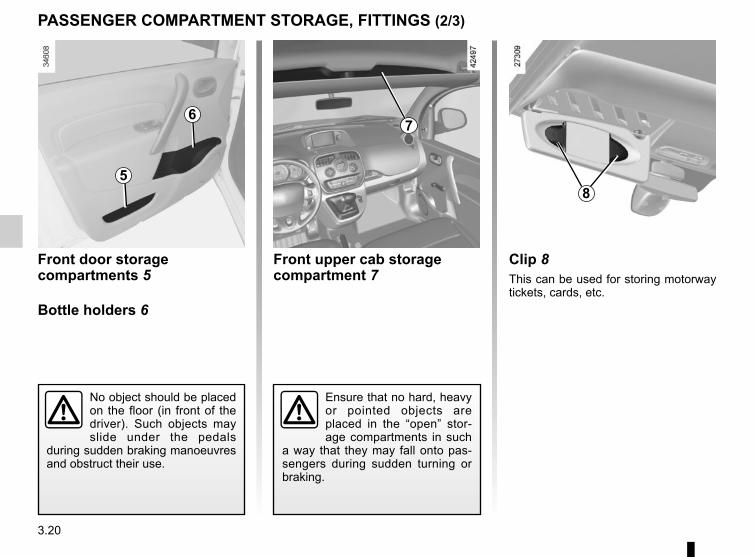
3.20
Front upper cab storage compartment 7
Front door storage compartments 5
Bottle holders 6
PASSENGER COMPARTMENT STORAGE, FITTINGS (2/3)
No object should be placed on the floor (in front of the driver). Such objects may slide under the pedals
during sudden braking manoeuvres and obstruct their use.
Clip 8This can be used for storing motorway tickets, cards, etc.
Ensure that no hard, heavy or pointed objects are placed in the “open” stor-age compartments in such
a way that they may fall onto pas-sengers during sudden turning or braking.
5
67
8
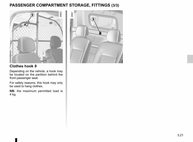
3.21
PASSENGER COMPARTMENT STORAGE, FITTINGS (3/3)
Clothes hook 9Depending on the vehicle, a hook may be located on the partition behind the front passenger seat.For safety reasons, this hook may only be used to hang clothes.NB: the maximum permitted load is 4 kg.
99
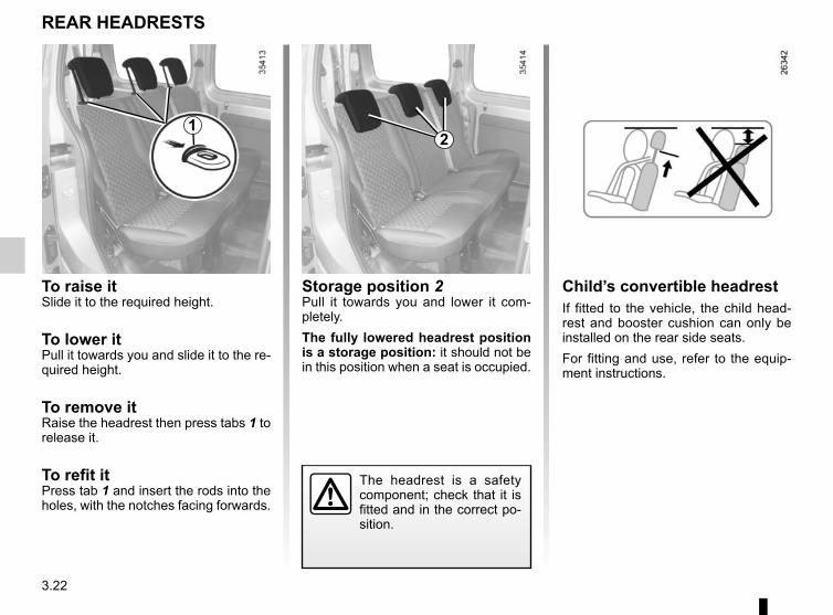
3.22
The headrest is a safety component; check that it is fitted and in the correct po-sition.
Storage position 2Pull it towards you and lower it com-pletely.The fully lowered headrest position is a storage position: it should not be in this position when a seat is occupied.
To raise itSlide it to the required height.
To lower itPull it towards you and slide it to the re-quired height.
To remove itRaise the headrest then press tabs 1 to release it.
To refit itPress tab 1 and insert the rods into the holes, with the notches facing forwards.
REAR HEADRESTS
Child’s convertible headrestIf fitted to the vehicle, the child head-rest and booster cushion can only be installed on the rear side seats.For fitting and use, refer to the equip-ment instructions.
12
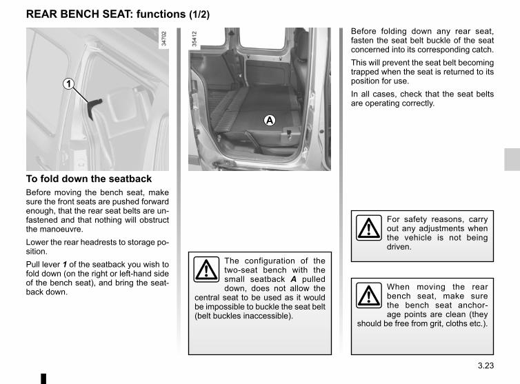
3.23
To fold down the seatbackBefore moving the bench seat, make sure the front seats are pushed forward enough, that the rear seat belts are un-fastened and that nothing will obstruct the manoeuvre.Lower the rear headrests to storage po-sition.Pull lever 1 of the seatback you wish to fold down (on the right or left-hand side of the bench seat), and bring the seat-back down.
REAR BENCH SEAT: functions (1/2)
For safety reasons, carry out any adjustments when the vehicle is not being driven.
When moving the rear bench seat, make sure the bench seat anchor-age points are clean (they
should be free from grit, cloths etc.).
1
Before folding down any rear seat, fasten the seat belt buckle of the seat concerned into its corresponding catch.This will prevent the seat belt becoming trapped when the seat is returned to its position for use.In all cases, check that the seat belts are operating correctly.
The configuration of the two-seat bench with the small seatback A pulled down, does not allow the
central seat to be used as it would be impossible to buckle the seat belt (belt buckles inaccessible).
A
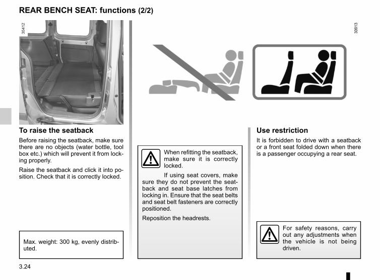
3.24
REAR BENCH SEAT: functions (2/2)
Use restrictionIt is forbidden to drive with a seatback or a front seat folded down when there is a passenger occupying a rear seat.
For safety reasons, carry out any adjustments when the vehicle is not being driven.
To raise the seatbackBefore raising the seatback, make sure there are no objects (water bottle, tool box etc.) which will prevent it from lock-ing properly.Raise the seatback and click it into po-sition. Check that it is correctly locked.
When refitting the seatback, make sure it is correctly locked.If using seat covers, make
sure they do not prevent the seat-back and seat base latches from locking in. Ensure that the seat belts and seat belt fasteners are correctly positioned.Reposition the headrests.
Max. weight: 300 kg, evenly distrib-uted.
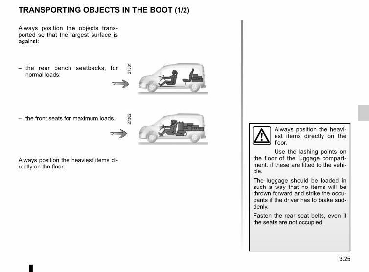
3.25
Always position the heavi-est items directly on the floor.Use the lashing points on
the floor of the luggage compart-ment, if these are fitted to the vehi-cle. The luggage should be loaded in such a way that no items will be thrown forward and strike the occu-pants if the driver has to brake sud-denly.Fasten the rear seat belts, even if the seats are not occupied.
TRANSPORTING OBJECTS IN THE BOOT (1/2)
Always position the objects trans-ported so that the largest surface is against:
– the rear bench seatbacks, for normal loads;
– the front seats for maximum loads.
Always position the heaviest items di-rectly on the floor.
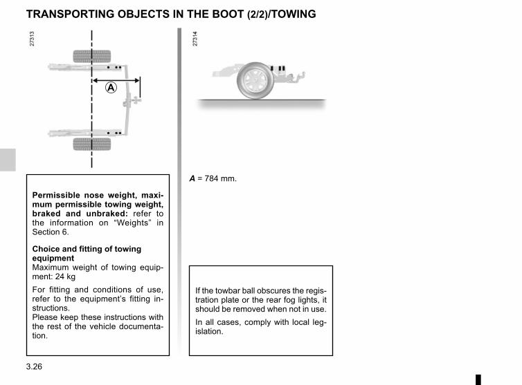
3.26
TRANSPORTING OBJECTS IN THE BOOT (2/2)/TOWING
If the towbar ball obscures the regis-tration plate or the rear fog lights, it should be removed when not in use.In all cases, comply with local leg-islation.
A = 784 mm.
A
Permissible nose weight, maxi-mum permissible towing weight, braked and unbraked: refer to the information on “Weights” in Section 6.
Choice and fitting of towing equipmentMaximum weight of towing equip-ment: 24 kgFor fitting and conditions of use, refer to the equipment’s fitting in-structions.Please keep these instructions with the rest of the vehicle documenta-tion.
4.1
Section 4: Maintenance
Bonnet . . . . . . . . . . . . . . . . . . . . . . . . . . . . . . . . . . . . . . . . . . . . . . . . . . . . . . . . . . . . . . . . . . . . . . . . 4.2Levels . . . . . . . . . . . . . . . . . . . . . . . . . . . . . . . . . . . . . . . . . . . . . . . . . . . . . . . . . . . . . . . . . . . . . . . . 4.4
coolant . . . . . . . . . . . . . . . . . . . . . . . . . . . . . . . . . . . . . . . . . . . . . . . . . . . . . . . . . . . . . . . . . . 4.4brake fluid . . . . . . . . . . . . . . . . . . . . . . . . . . . . . . . . . . . . . . . . . . . . . . . . . . . . . . . . . . . . . . . . 4.5windscreen washer reservoir . . . . . . . . . . . . . . . . . . . . . . . . . . . . . . . . . . . . . . . . . . . . . . . . . 4.5
12 volt battery . . . . . . . . . . . . . . . . . . . . . . . . . . . . . . . . . . . . . . . . . . . . . . . . . . . . . . . . . . . . . . . . . . 4.6Tyre pressure. . . . . . . . . . . . . . . . . . . . . . . . . . . . . . . . . . . . . . . . . . . . . . . . . . . . . . . . . . . . . . . . . . . 4.8Bodywork maintenance . . . . . . . . . . . . . . . . . . . . . . . . . . . . . . . . . . . . . . . . . . . . . . . . . . . . . . . . . . . 4.10Interior trim maintenance . . . . . . . . . . . . . . . . . . . . . . . . . . . . . . . . . . . . . . . . . . . . . . . . . . . . . . . . . . 4.13
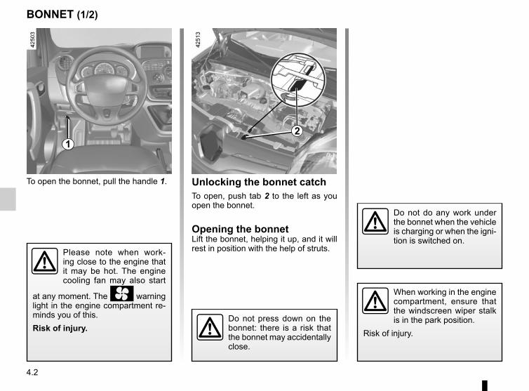
4.2
BONNET (1/2)
1
Do not do any work under the bonnet when the vehicle is charging or when the igni-tion is switched on.
To open the bonnet, pull the handle 1. Unlocking the bonnet catchTo open, push tab 2 to the left as you open the bonnet.
Opening the bonnetLift the bonnet, helping it up, and it will rest in position with the help of struts.
Do not press down on the bonnet: there is a risk that the bonnet may accidentally close.
When working in the engine compartment, ensure that the windscreen wiper stalk is in the park position.
Risk of injury.
2
Please note when work-ing close to the engine that it may be hot. The engine cooling fan may also start
at any moment. The warning light in the engine compartment re-minds you of this.Risk of injury.
4.3
Ensure that the bonnet is properly locked.Check that nothing is pre-venting the catch from lock-
ing (gravel, cloth, etc.).
BONNET (2/2)
Closing the bonnetCheck that nothing has been left in the engine compartment.To close the bonnet again, hold the bonnet in the middle and lower it to 30 cm above the closed position, then re-lease it.
After carrying out any work in the engine compart-ment, check that nothing has been left behind (cloth,
tools, etc.).These may damage the engine or cause a fire.
In the event of even a slight impact involving the radia-tor grille or bonnet, have the bonnet lock checked by
an approved dealer as soon as pos-sible.
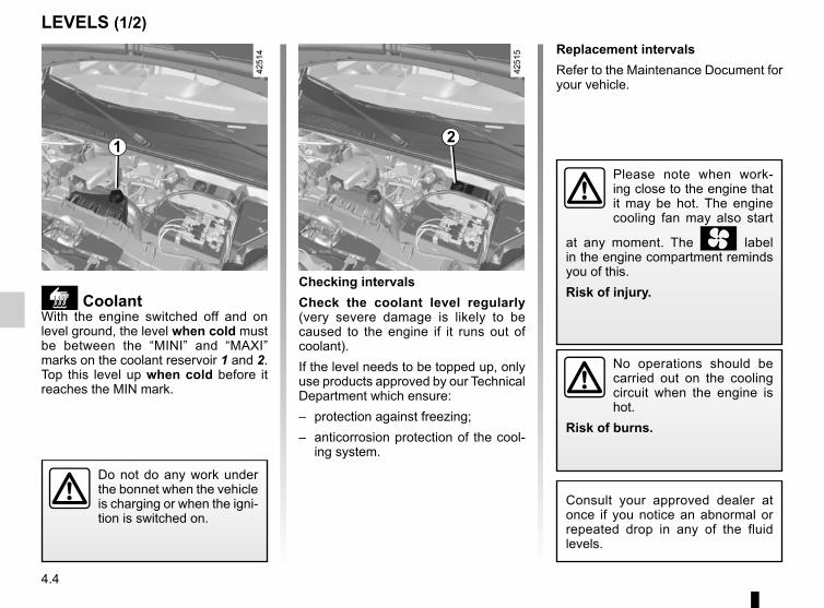
4.4
Replacement intervalsRefer to the Maintenance Document for your vehicle.
LEVELS (1/2)
CoolantWith the engine switched off and on level ground, the level when cold must be between the “MINI” and “MAXI” marks on the coolant reservoir 1 and 2.Top this level up when cold before it reaches the MIN mark.
Checking intervalsCheck the coolant level regularly (very severe damage is likely to be caused to the engine if it runs out of coolant).If the level needs to be topped up, only use products approved by our Technical Department which ensure:– protection against freezing;– anticorrosion protection of the cool-
ing system.
No operations should be carried out on the cooling circuit when the engine is hot.
Risk of burns.
Consult your approved dealer at once if you notice an abnormal or repeated drop in any of the fluid levels.
1 2
Do not do any work under the bonnet when the vehicle is charging or when the igni-tion is switched on.
Please note when work-ing close to the engine that it may be hot. The engine cooling fan may also start
at any moment. The label in the engine compartment reminds you of this.Risk of injury.
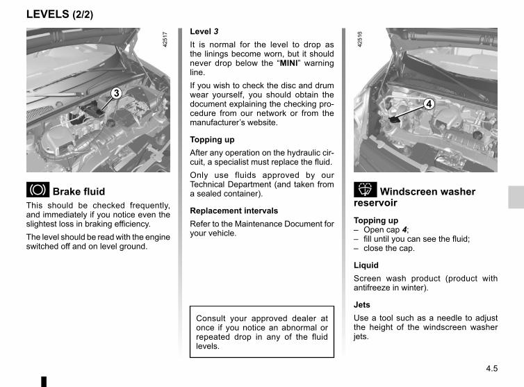
4.5
Windscreen washer reservoirTopping up– Open cap 4;– fill until you can see the fluid;– close the cap.
LiquidScreen wash product (product with antifreeze in winter).
JetsUse a tool such as a needle to adjust the height of the windscreen washer jets.
4
Level 3It is normal for the level to drop as the linings become worn, but it should never drop below the “MINI” warning line.If you wish to check the disc and drum wear yourself, you should obtain the document explaining the checking pro-cedure from our network or from the manufacturer’s website.
Topping upAfter any operation on the hydraulic cir-cuit, a specialist must replace the fluid.Only use fluids approved by our Technical Department (and taken from a sealed container).
Replacement intervalsRefer to the Maintenance Document for your vehicle.
Consult your approved dealer at once if you notice an abnormal or repeated drop in any of the fluid levels.
Brake fluidThis should be checked frequently, and immediately if you notice even the slightest loss in braking efficiency.The level should be read with the engine switched off and on level ground.
3
LEVELS (2/2)
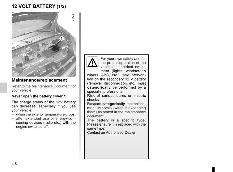
4.6
Maintenance/replacementRefer to the Maintenance Document for your vehicle.Never open the battery cover 1.The charge status of the 12V battery can decrease, especially if you use your vehicle:– when the exterior temperature drops;– after extended use of energy-con-
suming devices (radio etc.) with the engine switched off.
12 VOLT BATTERY (1/2)
1
For your own safety and for the proper operation of the vehicle’s electrical equip-ment (lights, windscreen
wipers, ABS, etc.), any interven-tion on the secondary 12 V battery (removal, disconnection, etc.) must categorically be performed by a specialist professional.Risk of serious burns or electric shocks. Respect categorically the replace-ment intervals (without exceeding them) as stated in the maintenance document.The battery is a specific type. Please ensure it is replaced with the same type.Contact an Authorised Dealer.
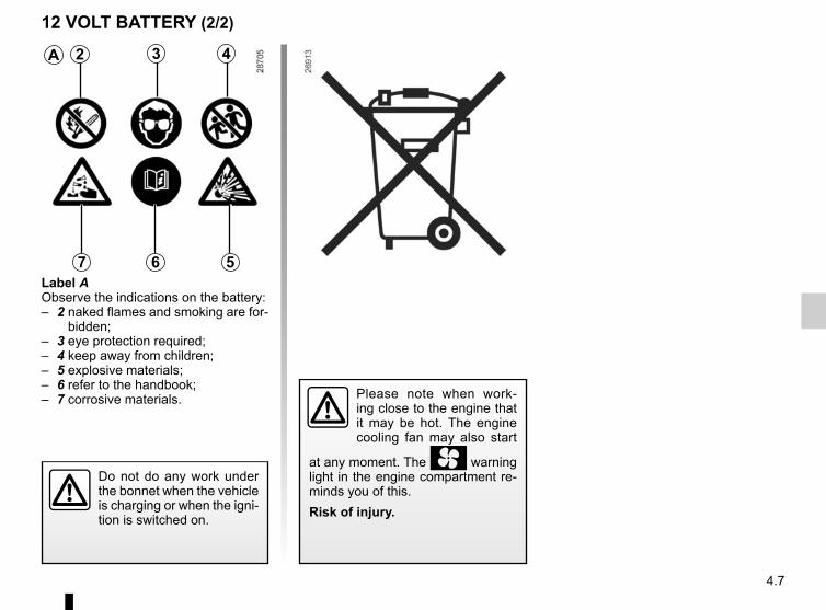
4.7
A 2 3 4
567Label AObserve the indications on the battery:– 2 naked flames and smoking are for-
bidden;– 3 eye protection required;– 4 keep away from children;– 5 explosive materials;– 6 refer to the handbook;– 7 corrosive materials. Please note when work-
ing close to the engine that it may be hot. The engine cooling fan may also start
at any moment. The warning light in the engine compartment re-minds you of this.Risk of injury.
12 VOLT BATTERY (2/2)
Do not do any work under the bonnet when the vehicle is charging or when the igni-tion is switched on.
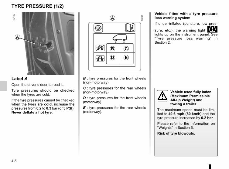
4.8
A
B : tyre pressures for the front wheels (non-motorway).C : tyre pressures for the rear wheels (non-motorway).D : tyre pressures for the front wheels (motorway).E : tyre pressures for the rear wheels (motorway).
B C
ED
A
Label AOpen the driver’s door to read it.Tyre pressures should be checked when the tyres are cold.If the tyre pressures cannot be checked when the tyres are cold, increase the pressures from 0.2 to 0.3 bar (or 3 PSI). Never deflate a hot tyre.
TYRE PRESSURE (1/2)
Vehicle used fully laden (Maximum Permissible All-up Weight) and towing a trailer
The maximum speed must be lim-ited to 49.6 mph (80 km/h) and the tyre pressure increased by 0.2 bar.Please refer to the information on “Weights” in Section 6.Risk of tyre blowouts.
Vehicle fitted with a tyre pressure loss warning systemIf under-inflated (puncture, low pres-
sure, etc.), the warning light lights up on the instrument panel. See “Tyre pressure loss warning” in Section 2.
4.9
TYRE PRESSURES (2/2)Tyre safety and use of snow chains: Refer to the information on “Tyres” in Section 5 for the servicing conditions and, depending on the version, the use of chains.
For your safety, please re-spect the speed limit.When they need to be re-placed, only tyres of the
same make, size, type and profile should be used on a single axle.They must: either have a load ca-pacity and speed rating at least equal to those of the original tyres, or conform to those recom-mended by an authorised dealer.Failure to heed these instructions could endanger your safety and affect your vehicle’s roadworthi-ness.Risk of loss of control of the ve-hicle.
4.10
BODYWORK MAINTENANCE (1/3)A well-maintained vehicle will last longer. It is therefore recommended to maintain the exterior of the vehicle reg-ularly.Your vehicle has been treated with very effective anti-corrosion products. It is nevertheless subject to various outside influences.
Corrosive agents in the atmosphere– atmospheric pollution (built-up and
industrial areas),– saline atmospheres (near the sea,
particularly in hot weather),– seasonal and damp weather condi-
tions (e.g. road salt in winter, water from road cleaners, etc.).
Minor impacts
Abrasive actionDust and sand in the air, mud, road grit thrown up by other vehicles, etc.You should take a number of minor pre-cautions in order to safeguard your ve-hicle against such risks.
You shouldWash your car frequently, with the engine off, with cleaning products rec-ommended by the manufacturer (never use abrasive products). Rinse thor-oughly beforehand with a jet:– spots of tree resin and industrial
grime;– mud in the wheel arches and under-
neath the body which forms damp patches;
– bird droppings, which cause a chemical reaction with the paint that rapidly discolours paintwork and may even cause the paint to peel off;
wash the vehicle immediately to remove these marks since it is im-possible to remove them by polish-ing;
– salt, particularly in the wheel arches and underneath the body after driv-ing in areas where the roads have been gritted.
Withdraw the vegetable falls (resin, film etc.) from the vehicle regularly.
Observe the vehicle stopping distances when driving on gravelled surfaces to prevent paint damage.Repair, or have repaired quickly, areas where the paint has been damaged, to prevent corrosion spreading.Remember to visit the body shop pe-riodically in order to maintain your anti-corrosion warranty. Refer to the Maintenance Document.Respect local regulations about wash-ing vehicles (e.g. do not wash your ve-hicle on a public highway).If it is necessary to clean mechani-cal components, hinges, etc., spray them with products approved by our Technical Department to protect them after they have been cleaned.
We have selected special products to care for your vehicle and you can obtain these from the manufactur-er’s accessory outlets.
4.11
BODYWORK MAINTENANCE (2/3)
Degrease or clean using high-pressure cleaning equipment or by spray-ing on products not ap-proved by our Technical Department:
– mechanical components (e.g.: engine compartment);
– underbody;– parts with hinges (e.g.: inside the
doors);– painted plastic external fittings (e.g.:
bumpers).Doing this could give rise to corrosion or operational faults.
What you should not doWash the vehicle in bright sunlight or freezing temperatures.Do not scrape off mud or dirt without pre-wetting.Allow dirt to accumulate on the exterior.Allow rust to form following minor im-pacts.Do not use solvents not approved by our Technical Department to remove stains as this could damage the paint-work.Do not drive in snow or muddy condi-tions without washing the vehicle, par-ticularly under the wheel arches and body.
4.12
Using a roller type car washReturn the windscreen wiper stalk to the Park position (refer to the informa-tion on the “Windscreen washer, wiper” in Section 1). Check the mounting of external accessories, additional lights and mirrors, and ensure that the wiper blades are secured with adhesive tape.Remove the radio aerial mast if your vehicle is fitted with this equipment. Remember to remove the tape and refit the antenna after washing.
BODYWORK MAINTENANCE (3/3)
Cleaning the headlightsAs the headlights are made of plastic “glass”, use a soft cloth or cotton wool to clean them. If this does not clean them properly, moisten the cloth with soapy water, then wipe clean with a soft damp cloth or cotton wool.Finally, carefully dry off with a soft dry cloth.Do not use cleaning products con-taining alcohol or utensils (e.g.: a scraper).
Washing the vehicleNever wash the engine compartment, the charging connection or the traction
battery with a high-pressure jet.This risks damaging the electric cir-cuit.Never wash the vehicle while it is charging.Risk of electric shock and a risk to life.
Vehicles with a matte paint finishThis type of paint requires certain pre-cautions.
Do not do the followingUse wax-based products (polishing).Rub too hard.Wash the vehicle in a roller-type car wash.Wash the vehicle using a high-pressure device.Attach stickers to the paintwork (risk of leaving marks).
Wash the vehicle using a high-pressure cleaning device.
You should do the followingWash the vehicle by hand using plenty of water, using a soft cloth or a gentle sponge.
4.13
Glass instrument panel(e.g. instrument panel, clock, exterior temperature display, radio display, etc.)Use a soft cloth (or cotton wool).If this does not clean them properly, use a soft cloth (or cotton wool) slightly moistened with soapy water and then wipe clean with another soft damp cloth or cotton wool.Finally, carefully dry off with a soft dry cloth.Do not use products containing alco-hol and/or spray fluids on the area.
Seat beltsThese must be kept clean.Use products selected by our Technical Department (Approved outlets) or warm, soapy water and a sponge and wipe with a dry cloth.Detergents or dyes must not be used under any circumstances.
INTERIOR TRIM MAINTENANCE (1/2)
Textiles (seats, door trim, etc)Vacuum-clean the textiles regularly.
Liquid stainUse soapy water.Dab lightly (never rub) with a soft cloth, rinse and remove the excess.
Solid or pasty stainCarefully remove the excess solid or pasty material immediately with a spatula (working from the edges to the centre to avoid spreading the stain).Clean as for a liquid stain.
Special instructions for sweets or chewing gumPut an ice cube on the stain to solidify it, then proceed as for a solid stain.
A well-maintained vehicle will last longer. It is therefore recommended to maintain the interior of the vehicle regu-larly.A stain should always be dealt with swiftly.Whatever type of stain is on the trim, use cold (or warm) soapy water with natural soap.Detergents (washing-up liquid, pow-dered products, alcohol-based prod-ucts) should not be used.Use a soft cloth.Rinse and soak up the excess.
For further recommendations for maintaining the interior, and/or for any unsatisfactory results, please see an authorised dealer.
4.14
You should not:Position objects such as deodorants, scents etc. near air vents as this could damage your dashboard trim.
Use high-pressure cleaning equipment or sprays inside the pas-senger compartment:
without careful use, this equipment could impair the correct functioning of the electrical or electronic compo-nents in the vehicle, or have other detrimental effects.
INTERIOR TRIM MAINTENANCE (2/2)
Removal/replacing removable equipment originally fitted in the vehicleIf you need to remove equipment in order to clean the passenger com-partment (for example, mats), always ensure that they are correctly refitted and are the right way around (the driv-er’s mat should be fitted on the driver’s side, etc.) and fit them with the compo-nents supplied with the equipment (for example, the driver mat should always be fixed using the pre-fitted mounting components).With the vehicle stationary, always ensure that nothing will impede driving (anything obstructing the pedals, heel wedged by the mat etc.).
5.1
Section 5: Practical advice
Puncture . . . . . . . . . . . . . . . . . . . . . . . . . . . . . . . . . . . . . . . . . . . . . . . . . . . . . . . . . . . . . . . . . . . . . . 5.2Emergency spare wheel . . . . . . . . . . . . . . . . . . . . . . . . . . . . . . . . . . . . . . . . . . . . . . . . . . . . . . . . . . 5.2Tyre inflation kit . . . . . . . . . . . . . . . . . . . . . . . . . . . . . . . . . . . . . . . . . . . . . . . . . . . . . . . . . . . . . . . . . 5.3Tool kit . . . . . . . . . . . . . . . . . . . . . . . . . . . . . . . . . . . . . . . . . . . . . . . . . . . . . . . . . . . . . . . . . . . . . . . . 5.6Wheels, trim . . . . . . . . . . . . . . . . . . . . . . . . . . . . . . . . . . . . . . . . . . . . . . . . . . . . . . . . . . . . . . . . . . . . 5.7Changing a wheel . . . . . . . . . . . . . . . . . . . . . . . . . . . . . . . . . . . . . . . . . . . . . . . . . . . . . . . . . . . . . . . 5.8Tyres . . . . . . . . . . . . . . . . . . . . . . . . . . . . . . . . . . . . . . . . . . . . . . . . . . . . . . . . . . . . . . . . . . . . . . . . . 5.10Headlights: changing bulbs . . . . . . . . . . . . . . . . . . . . . . . . . . . . . . . . . . . . . . . . . . . . . . . . . . . . . . . . 5.13Fog lights: changing bulbs . . . . . . . . . . . . . . . . . . . . . . . . . . . . . . . . . . . . . . . . . . . . . . . . . . . . . . . . . 5.15Rear lights: changing bulbs . . . . . . . . . . . . . . . . . . . . . . . . . . . . . . . . . . . . . . . . . . . . . . . . . . . . . . . . 5.16Indicator lights: changing bulbs . . . . . . . . . . . . . . . . . . . . . . . . . . . . . . . . . . . . . . . . . . . . . . . . . . . . . 5.19Interior lighting: changing bulbs . . . . . . . . . . . . . . . . . . . . . . . . . . . . . . . . . . . . . . . . . . . . . . . . . . . . . 5.20Fuses . . . . . . . . . . . . . . . . . . . . . . . . . . . . . . . . . . . . . . . . . . . . . . . . . . . . . . . . . . . . . . . . . . . . . . . . . 5.21Wiper blades . . . . . . . . . . . . . . . . . . . . . . . . . . . . . . . . . . . . . . . . . . . . . . . . . . . . . . . . . . . . . . . . . . . 5.23Towing/breakdown . . . . . . . . . . . . . . . . . . . . . . . . . . . . . . . . . . . . . . . . . . . . . . . . . . . . . . . . . . . . . . . 5.25Fitting a radio . . . . . . . . . . . . . . . . . . . . . . . . . . . . . . . . . . . . . . . . . . . . . . . . . . . . . . . . . . . . . . . . . . . 5.28Accessories . . . . . . . . . . . . . . . . . . . . . . . . . . . . . . . . . . . . . . . . . . . . . . . . . . . . . . . . . . . . . . . . . . . . 5.29Radio frequency remote control: batteries. . . . . . . . . . . . . . . . . . . . . . . . . . . . . . . . . . . . . . . . . . . . . 5.31Operating faults . . . . . . . . . . . . . . . . . . . . . . . . . . . . . . . . . . . . . . . . . . . . . . . . . . . . . . . . . . . . . . . . . 5.32
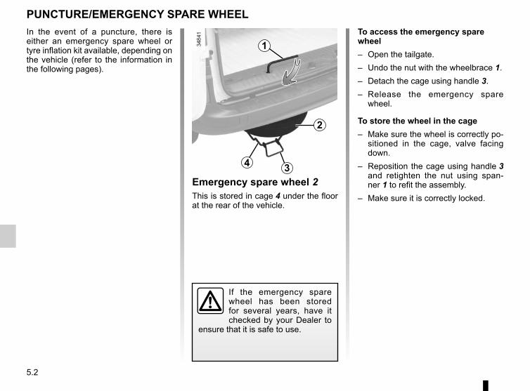
5.2
PUNCTURE/EMERGENCY SPARE WHEELTo access the emergency spare wheel– Open the tailgate.– Undo the nut with the wheelbrace 1.– Detach the cage using handle 3.– Release the emergency spare
wheel.
To store the wheel in the cage– Make sure the wheel is correctly po-
sitioned in the cage, valve facing down.
– Reposition the cage using handle 3 and retighten the nut using span-ner 1 to refit the assembly.
– Make sure it is correctly locked.
If the emergency spare wheel has been stored for several years, have it checked by your Dealer to
ensure that it is safe to use.
2
3
1
Emergency spare wheel 2This is stored in cage 4 under the floor at the rear of the vehicle.
4
In the event of a puncture, there is either an emergency spare wheel or tyre inflation kit available, depending on the vehicle (refer to the information in the following pages).
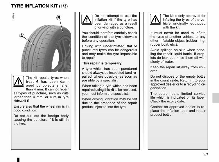
5.3
TYRE INFLATION KIT (1/3)
The kit is only approved for inflating the tyres of the ve-hicle originally equipped with the kit.
It must never be used to inflate the tyres of another vehicle, or any other inflatable object (rubber ring, rubber boat, etc.).Avoid spillage on skin when hand-ling the repair liquid bottle. If drop-lets do leak out, rinse them off with plenty of water.Keep the repair kit away from chil-dren.Do not dispose of the empty bottle in the countryside. Return it to your approved dealer or to a recycling or-ganisation.The bottle has a limited service life which is indicated on its label. Check the expiry date.Contact an approved dealer to re-place the inflation tube and repair product bottle.
A
B
The kit repairs tyres when tread A has been dam-aged by objects smaller than 4 mm. It cannot repair
all types of puncture, such as cuts larger than 4 mm, or cuts in tyre sidewall B.Ensure also that the wheel rim is in good condition.Do not pull out the foreign body causing the puncture if it is still in the tyre.
Do not attempt to use the inflation kit if the tyre has been damaged as a result of driving with a puncture.
You should therefore carefully check the condition of the tyre sidewalls before any operation.Driving with underinflated, flat or punctured tyres can be dangerous and may make the tyre impossible to repair.This repair is temporary.A tyre which has been punctured should always be inspected (and re-paired, where possible) as soon as possible by a specialist.When taking a tyre which has been repaired using this kit to be replaced, you must inform the specialist.When driving, vibration may be felt due to the presence of the repair product injected into the tyre.
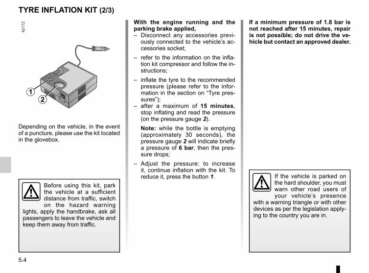
5.4
TYRE INFLATION KIT (2/3)
Depending on the vehicle, in the event of a puncture, please use the kit located in the glovebox.
Before using this kit, park the vehicle at a sufficient distance from traffic, switch on the hazard warning
lights, apply the handbrake, ask all passengers to leave the vehicle and keep them away from traffic.
If the vehicle is parked on the hard shoulder, you must warn other road users of your vehicle’s presence
with a warning triangle or with other devices as per the legislation apply-ing to the country you are in.
With the engine running and the parking brake applied,– Disconnect any accessories previ-
ously connected to the vehicle’s ac-cessories socket;
– refer to the information on the infla-tion kit compressor and follow the in-structions;
– inflate the tyre to the recommended pressure (please refer to the infor-mation in the section on “Tyre pres-sures”);
– after a maximum of 15 minutes, stop inflating and read the pressure (on the pressure gauge 2).Note: while the bottle is emptying (approximately 30 seconds), the pressure gauge 2 will indicate briefly a pressure of 6 bar, then the pres-sure drops;
– Adjust the pressure: to increase it, continue inflation with the kit. To reduce it, press the button 1.
21
If a minimum pressure of 1.8 bar is not reached after 15 minutes, repair is not possible; do not drive the ve-hicle but contact an approved dealer.
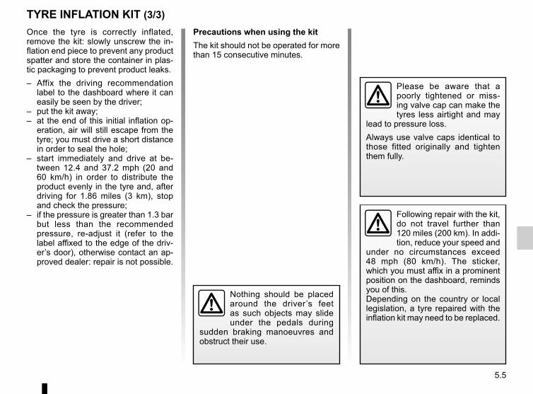
5.5
TYRE INFLATION KIT (3/3)Once the tyre is correctly inflated, remove the kit: slowly unscrew the in-flation end piece to prevent any product spatter and store the container in plas-tic packaging to prevent product leaks.– Affix the driving recommendation
label to the dashboard where it can easily be seen by the driver;
– put the kit away;– at the end of this initial inflation op-
eration, air will still escape from the tyre; you must drive a short distance in order to seal the hole;
– start immediately and drive at be-tween 12.4 and 37.2 mph (20 and 60 km/h) in order to distribute the product evenly in the tyre and, after driving for 1.86 miles (3 km), stop and check the pressure;
– if the pressure is greater than 1.3 bar but less than the recommended pressure, re-adjust it (refer to the label affixed to the edge of the driv-er’s door), otherwise contact an ap-proved dealer: repair is not possible.
Precautions when using the kitThe kit should not be operated for more than 15 consecutive minutes.
Nothing should be placed around the driver’s feet as such objects may slide under the pedals during
sudden braking manoeuvres and obstruct their use.
Please be aware that a poorly tightened or miss-ing valve cap can make the tyres less airtight and may
lead to pressure loss.Always use valve caps identical to those fitted originally and tighten them fully.
Following repair with the kit, do not travel further than 120 miles (200 km). In addi-tion, reduce your speed and
under no circumstances exceed 48 mph (80 km/h). The sticker, which you must affix in a prominent position on the dashboard, reminds you of this.Depending on the country or local legislation, a tyre repaired with the inflation kit may need to be replaced.
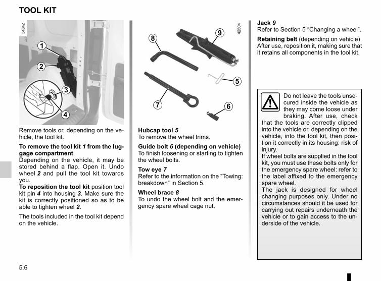
5.6
Remove tools or, depending on the ve-hicle, the tool kit.To remove the tool kit 1 from the lug-gage compartmentDepending on the vehicle, it may be stored behind a flap. Open it. Undo wheel 2 and pull the tool kit towards you.To reposition the tool kit position tool kit pin 4 into housing 3. Make sure the kit is correctly positioned so as to be able to tighten wheel 2.The tools included in the tool kit depend on the vehicle.
TOOL KIT
1
3
2
4
Do not leave the tools unse-cured inside the vehicle as they may come loose under braking. After use, check
that the tools are correctly clipped into the vehicle or, depending on the vehicle, into the tool kit, then posi-tion it correctly in its housing: risk of injury.If wheel bolts are supplied in the tool kit, you must use these bolts only for the emergency spare wheel: refer to the label affixed to the emergency spare wheel.The jack is designed for wheel changing purposes only. Under no circumstances should it be used for carrying out repairs underneath the vehicle or to gain access to the un-derside of the vehicle.
Jack 9Refer to Section 5 “Changing a wheel”.Retaining belt (depending on vehicle)After use, reposition it, making sure that it retains all components in the tool kit.
5
67
89
Hubcap tool 5To remove the wheel trims.Guide bolt 6 (depending on vehicle)To finish loosening or starting to tighten the wheel bolts.Tow eye 7Refer to the information on the “Towing: breakdown” in Section 5.Wheel brace 8To undo the wheel bolt and the emer-gency spare wheel cage nut.
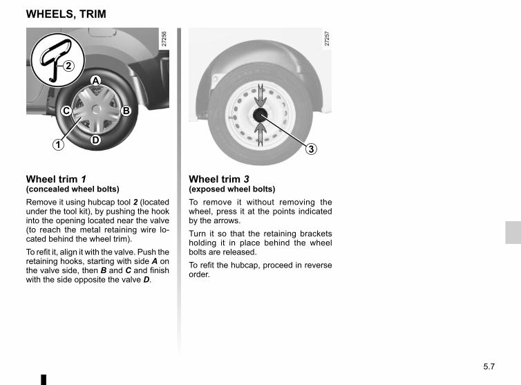
5.7
Wheel trim 3(exposed wheel bolts)To remove it without removing the wheel, press it at the points indicated by the arrows.Turn it so that the retaining brackets holding it in place behind the wheel bolts are released.To refit the hubcap, proceed in reverse order.
Wheel trim 1(concealed wheel bolts)Remove it using hubcap tool 2 (located under the tool kit), by pushing the hook into the opening located near the valve (to reach the metal retaining wire lo-cated behind the wheel trim).To refit it, align it with the valve. Push the retaining hooks, starting with side A on the valve side, then B and C and finish with the side opposite the valve D.
WHEELS, TRIM
1 3
A
B
D
C
2
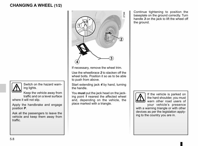
5.8
2
4
1
3
If necessary, remove the wheel trim.Use the wheelbrace 2 to slacken off the wheel bolts. Position it so as to be able to push from above.Start extending jack 4 by hand, turning the handle.You must put the jack head on the jack-ing point 1 nearest the affected wheel and, depending on the vehicle, the place marked with a triangle.
Switch on the hazard warn-ing lights.Keep the vehicle away from traffic and on a level surface
where it will not slip.Apply the handbrake and engage position P.Ask all the passengers to leave the vehicle and keep them away from traffic.
CHANGING A WHEEL (1/2)Continue tightening to position the baseplate on the ground correctly. Turn handle 3 on the jack to lift the wheel off the ground.
If the vehicle is parked on the hard shoulder, you must warn other road users of your vehicle’s presence
with a warning triangle or with other devices as per the legislation apply-ing to the country you are in.
5.9
Undo the bolts and take off the wheel. For vehicles fitted with alloy wheels, use the guide bolt located in the tool kit to finish loosening and start tightening the bolts.Fit the emergency spare wheel on the central hub and turn it to align the mounting holes in the wheel and the hub.Tighten the bolts and lower the jack.If bolts are supplied with the emergency spare wheel, only use these bolts for the emergency spare wheel.Tighten the bolts, checking that the wheel is correctly positioned on its hub and unscrew the jack.With the wheels on the ground, tighten the bolts fully and check they are tight as quickly as possible.
CHANGING A WHEEL (2/2)
Anti-theft boltsIf you use anti-theft bolts, fit these nearest the valve (wheel trim may not be able to fit).
If you have a puncture, re-place the wheel as soon as possible.A tyre which has been punc-
tured should always be inspected (and repaired, where possible) by a specialist.
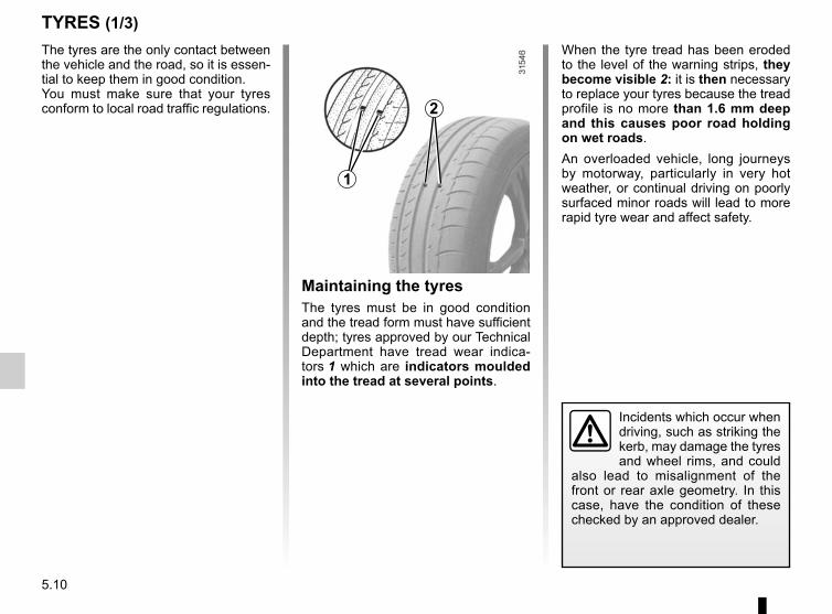
5.10
TYRES (1/3)
Maintaining the tyresThe tyres must be in good condition and the tread form must have sufficient depth; tyres approved by our Technical Department have tread wear indica-tors 1 which are indicators moulded into the tread at several points.
The tyres are the only contact between the vehicle and the road, so it is essen-tial to keep them in good condition.You must make sure that your tyres conform to local road traffic regulations.
When the tyre tread has been eroded to the level of the warning strips, they become visible 2: it is then necessary to replace your tyres because the tread profile is no more than 1.6 mm deep and this causes poor road holding on wet roads.An overloaded vehicle, long journeys by motorway, particularly in very hot weather, or continual driving on poorly surfaced minor roads will lead to more rapid tyre wear and affect safety.
Incidents which occur when driving, such as striking the kerb, may damage the tyres and wheel rims, and could
also lead to misalignment of the front or rear axle geometry. In this case, have the condition of these checked by an approved dealer.
1
2
5.11
TYRES (2/3)Pressures should be checked when the tyres are cold; ignore higher pressures which may be reached in hot weather or following a fast journey.If tyre pressures cannot be checked when the tyres are cold, the normal pressures must be increased by 0.2 to 0.3 bar (or 3 PSI).Never deflate a hot tyre.
Fitting new tyresTyre pressuresRespect the tyre pressures (including the emergency spare wheel). Check them at least once a month and before a long journey (refer to the label on the edge of the driver’s door).Please refer to the information on “Tyre pressures” in Section 4.
Incorrect tyre pressures lead to abnormal tyre wear and unusually hot running. These are factors which
may seriously affect safety and lead to:– poor road holding;– risk of bursting or tread separa-
tion.The pressure depends on the load and the speed of use. Adjust the pressures according to the condi-tions of use (refer to the information on “Tyre pressures”).
Please be aware that a poorly tightened or miss-ing valve cap can make the tyres less airtight and lead
to pressure loss.Always use valve caps identical to those fitted originally and tighten them fully.
For your safety, please re-spect the speed limit.When they need to be re-placed, only tyres of the
same make, size, type and profile should be used on a single axle.They must: either have a load ca-pacity and a speed capacity at least equal to the original tyres, or correspond to those recom-mended by your authorised dealer.Failure to heed these instructions could endanger your safety and affect your vehicle’s roadworthi-ness.Risk of loss of control of the ve-hicle.
5.12
TYRES (3/3)
Changing wheels aroundThis practice is not recommended.
Emergency spare wheelRefer to the information on the “Emergency spare wheel” and in-structions on “Changing a wheel” in Section 5.
Use in winter– Chains
For safety reasons, fitting snow chains to the rear axle is strictly forbidden.Chains must not be fitted to tyres which are larger than those originally fitted to the vehicle.
Chains may only be fitted to tyres of the same size as those originally fitted to your vehicle.
Only certain chains can be fitted to tyres. Consult an approved Dealer.
– Snow or winter tyresWe would recommend that these be fitted to all four wheels to ensure that your vehicle retains maximum grip.Note: be aware that these tyres may sometimes have:– a direction of travel ;– a maximum speed index which may be lower than the maximum speed of your vehicle.
– Studded tyresThis type of equipment may only be used for a limited period and as laid down by local legislation.It is necessary to observe the speed specified by current legislation.These tyres must, at a minimum, be fitted to the two front wheels.
In all cases, we would recommend that you contact an approved dealer who will be able to advise you on the choice of equipment which is most suitable for your vehicle.
Note: the use of snow tyres, winter tyres or studded tyres significantly re-duces the vehicle range.
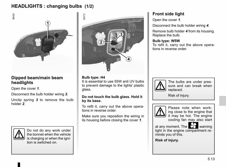
5.13
Front side lightOpen the cover 1.Disconnect the bulb holder wiring 4.Remove bulb holder 4 from its housing. Replace the bulb.Bulb type: W5WTo refit it, carry out the above opera-tions in reverse order.
Bulb type: H4It is essential to use 55W anti UV bulbs to prevent damage to the lights' plastic glass.
Do not touch the bulb glass. Hold it by its base.To refit it, carry out the above opera-tions in reverse order.Make sure you reposition the wiring in its housing before closing the cover 1.
The bulbs are under pres-sure and can break when replaced.Risk of injury.
HEADLIGHTS : changing bulbs (1/2)
Please note when work-ing close to the engine that it may be hot. The engine cooling fan may also start
at any moment. The warning light in the engine compartment re-minds you of this.Risk of injury.
Do not do any work under the bonnet when the vehicle is charging or when the igni-tion is switched on.
Dipped beam/main beam headlightsOpen the cover 1.Disconnect the bulb holder wiring 2.Unclip spring 3 to remove the bulb holder 2.
2
1
4
3
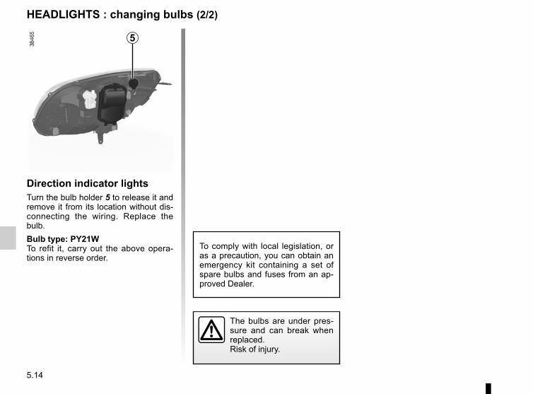
5.14
HEADLIGHTS : changing bulbs (2/2)
Direction indicator lightsTurn the bulb holder 5 to release it and remove it from its location without dis-connecting the wiring. Replace the bulb.Bulb type: PY21WTo refit it, carry out the above opera-tions in reverse order.
The bulbs are under pres-sure and can break when replaced.Risk of injury.
To comply with local legislation, or as a precaution, you can obtain an emergency kit containing a set of spare bulbs and fuses from an ap-proved Dealer.
5
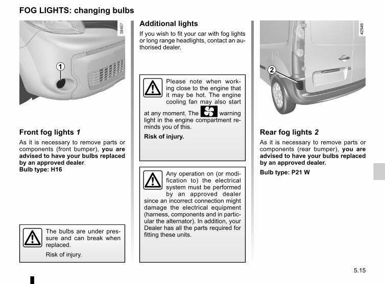
5.15
Front fog lights 1As it is necessary to remove parts or components (front bumper), you are advised to have your bulbs replaced by an approved dealer.Bulb type: H16
Additional lightsIf you wish to fit your car with fog lights or long range headlights, contact an au-thorised dealer.
FOG LIGHTS: changing bulbs
1
Please note when work-ing close to the engine that it may be hot. The engine cooling fan may also start
at any moment. The warning light in the engine compartment re-minds you of this.Risk of injury.
Any operation on (or modi-fication to) the electrical system must be performed by an approved dealer
since an incorrect connection might damage the electrical equipment (harness, components and in partic-ular the alternator). In addition, your Dealer has all the parts required for fitting these units.
Rear fog lights 2As it is necessary to remove parts or components (rear bumper), you are advised to have your bulbs replaced by an approved dealer.Bulb type: P21 W
2
The bulbs are under pres-sure and can break when replaced.Risk of injury.
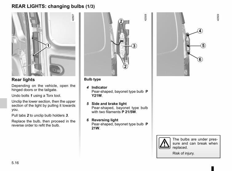
5.16
The bulbs are under pres-sure and can break when replaced.Risk of injury.
Bulb type
4 IndicatorPear-shaped, bayonet type bulb P Y21W.
5 Side and brake lightPear-shaped, bayonet type bulb with two filaments P 21/5W.
6 Reversing lightPear-shaped, bayonet type bulb P 21W.
Rear lightsDepending on the vehicle, open the hinged doors or the tailgate.Undo bolts 1 using a Torx tool.Unclip the lower section, then the upper section of the light by pulling it towards you.Pull tabs 2 to unclip bulb holders 3.Replace the bulb, then proceed in the reverse order to refit the bulb.
REAR LIGHTS: changing bulbs (1/3)
31
2
2
5
4
6
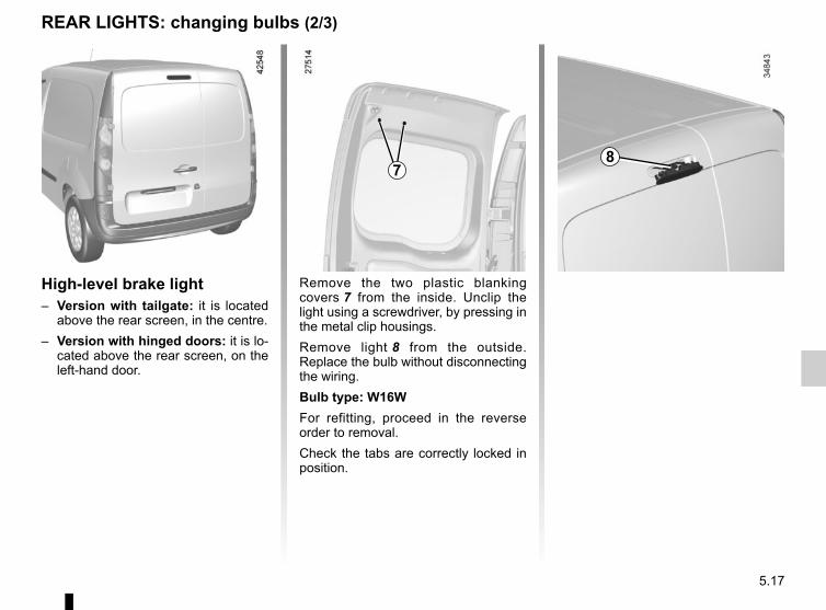
5.17
REAR LIGHTS: changing bulbs (2/3)
High-level brake light– Version with tailgate: it is located
above the rear screen, in the centre.– Version with hinged doors: it is lo-
cated above the rear screen, on the left-hand door.
Remove the two plastic blanking covers 7 from the inside. Unclip the light using a screwdriver, by pressing in the metal clip housings.Remove light 8 from the outside. Replace the bulb without disconnecting the wiring.Bulb type: W16WFor refitting, proceed in the reverse order to removal.Check the tabs are correctly locked in position.
78
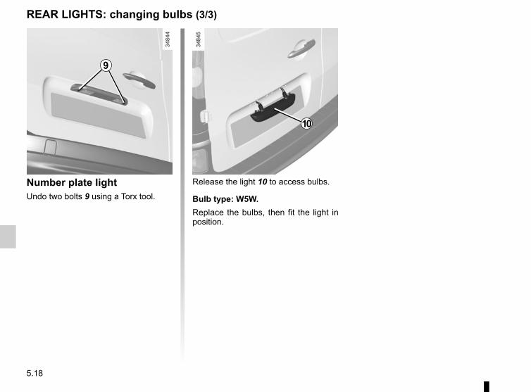
5.18
REAR LIGHTS: changing bulbs (3/3)
Release the light 10 to access bulbs.
Bulb type: W5W.Replace the bulbs, then fit the light in position.
Number plate lightUndo two bolts 9 using a Torx tool.
9
10
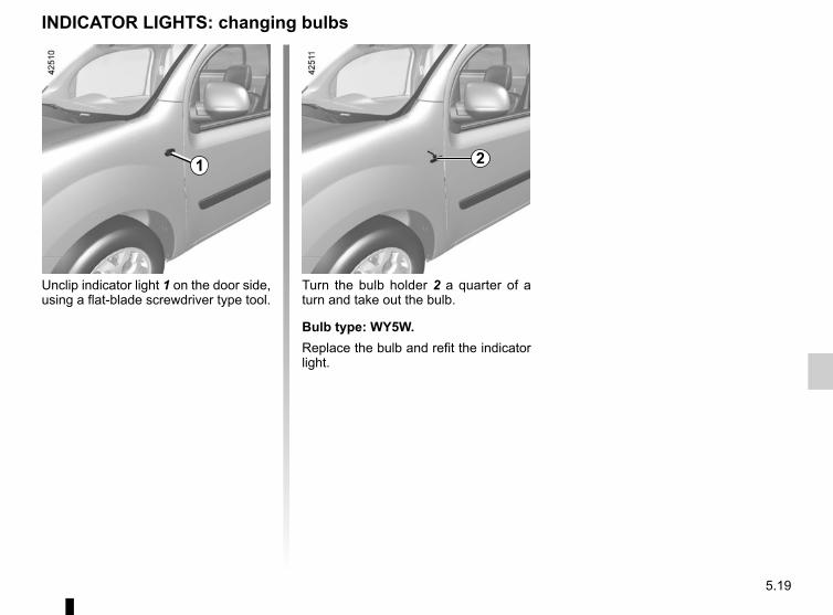
5.19
Turn the bulb holder 2 a quarter of a turn and take out the bulb.
Bulb type: WY5W.Replace the bulb and refit the indicator light.
Unclip indicator light 1 on the door side, using a flat-blade screwdriver type tool.
INDICATOR LIGHTS: changing bulbs
1 2
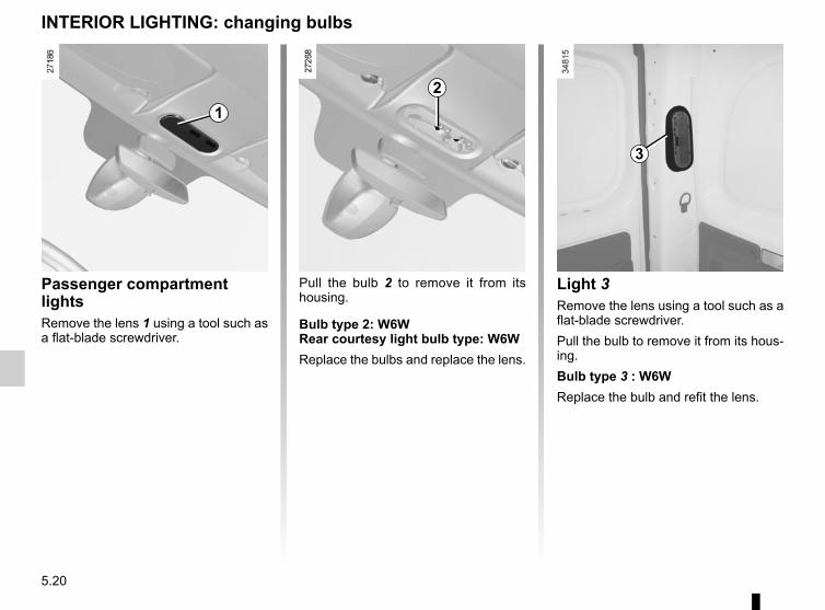
5.20
Passenger compartment lightsRemove the lens 1 using a tool such as a flat-blade screwdriver.
INTERIOR LIGHTING: changing bulbs
1
Pull the bulb 2 to remove it from its housing.
Bulb type 2: W6WRear courtesy light bulb type: W6WReplace the bulbs and replace the lens.
2
3
Light 3Remove the lens using a tool such as a flat-blade screwdriver.Pull the bulb to remove it from its hous-ing.Bulb type 3 : W6WReplace the bulb and refit the lens.
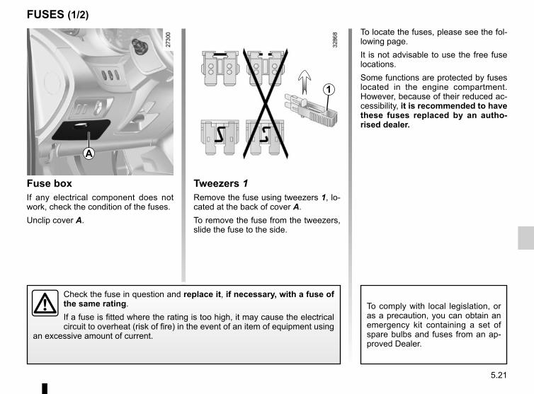
5.21
To comply with local legislation, or as a precaution, you can obtain an emergency kit containing a set of spare bulbs and fuses from an ap-proved Dealer.
FUSES (1/2)
Fuse boxIf any electrical component does not work, check the condition of the fuses. Unclip cover A.
To locate the fuses, please see the fol-lowing page.It is not advisable to use the free fuse locations.Some functions are protected by fuses located in the engine compartment. However, because of their reduced ac-cessibility, it is recommended to have these fuses replaced by an autho-rised dealer.
Check the fuse in question and replace it, if necessary, with a fuse of the same rating.If a fuse is fitted where the rating is too high, it may cause the electrical circuit to overheat (risk of fire) in the event of an item of equipment using
an excessive amount of current.
A
1
Tweezers 1Remove the fuse using tweezers 1, lo-cated at the back of cover A.To remove the fuse from the tweezers, slide the fuse to the side.
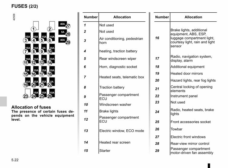
5.22
FUSES (2/2)
Number Allocation
1 Not used
2 Not used
3 Air conditioning, pedestrian horn
4 heating, traction battery
5 Rear windscreen wiper
6 Horn, diagnostic socket
7 Heated seats, telematic box
8 Traction battery
9 Passenger compartment ECU
10 Windscreen washer
11 Brake lights
12 Passenger compartment ECU
13 Electric window, ECO mode
14 Heated rear screen
15 Starter
1 2
3 4 5 6
7 8 9 10
11 12 13 14
15 16 17 18
19 20 21 22
23 24 25 26
27
28
29
Allocation of fusesThe presence of certain fuses de-pends on the vehicle equipment level.
Number Allocation
16
Brake lights, additional equipment, ABS, ESP, luggage compartment light, courtesy light, rain and light sensor
17 Radio, navigation system, display, alarm
18 Additional equipment
19 Heated door mirrors
20 Hazard lights, rear fog lights
21 Central locking of opening elements
22 Instrument panel
23 Not used
24 Radio, heated seats, brake lights
25 Front accessories socket
26 Towbar
27 Electric front windows
28 Rear-view mirror control
29 Passenger compartment motor-driven fan assembly
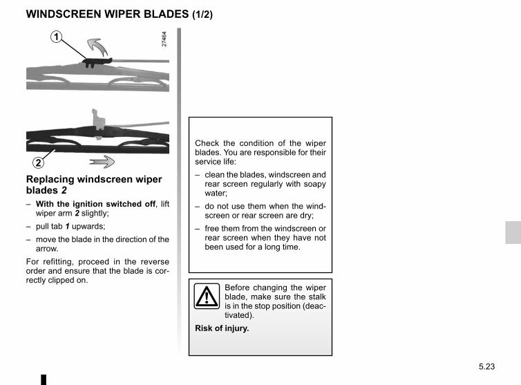
5.23
Replacing windscreen wiper blades 2– With the ignition switched off, lift
wiper arm 2 slightly;– pull tab 1 upwards;– move the blade in the direction of the
arrow.For refitting, proceed in the reverse order and ensure that the blade is cor-rectly clipped on.
WINDSCREEN WIPER BLADES (1/2)
Check the condition of the wiper blades. You are responsible for their service life:– clean the blades, windscreen and
rear screen regularly with soapy water;
– do not use them when the wind-screen or rear screen are dry;
– free them from the windscreen or rear screen when they have not been used for a long time.
1
2
Before changing the wiper blade, make sure the stalk is in the stop position (deac-tivated).
Risk of injury.
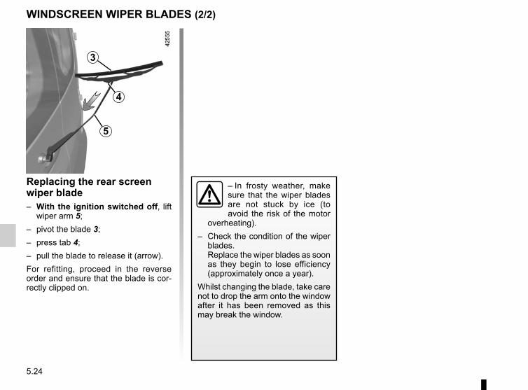
5.24
WINDSCREEN WIPER BLADES (2/2)
– In frosty weather, make sure that the wiper blades are not stuck by ice (to avoid the risk of the motor
overheating).– Check the condition of the wiper
blades.Replace the wiper blades as soon as they begin to lose efficiency (approximately once a year).
Whilst changing the blade, take care not to drop the arm onto the window after it has been removed as this may break the window.
Replacing the rear screen wiper blade– With the ignition switched off, lift
wiper arm 5;– pivot the blade 3;– press tab 4;– pull the blade to release it (arrow).For refitting, proceed in the reverse order and ensure that the blade is cor-rectly clipped on.
3
5
4
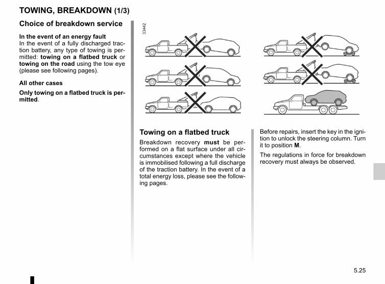
5.25
Choice of breakdown serviceIn the event of an energy faultIn the event of a fully discharged trac-tion battery, any type of towing is per-mitted: towing on a flatbed truck or towing on the road using the tow eye (please see following pages).
All other casesOnly towing on a flatbed truck is per-mitted.
TOWING, BREAKDOWN (1/3)
Before repairs, insert the key in the igni-tion to unlock the steering column. Turn it to position M.The regulations in force for breakdown recovery must always be observed.
Towing on a flatbed truckBreakdown recovery must be per-formed on a flat surface under all cir-cumstances except where the vehicle is immobilised following a full discharge of the traction battery. In the event of a total energy loss, please see the follow-ing pages.
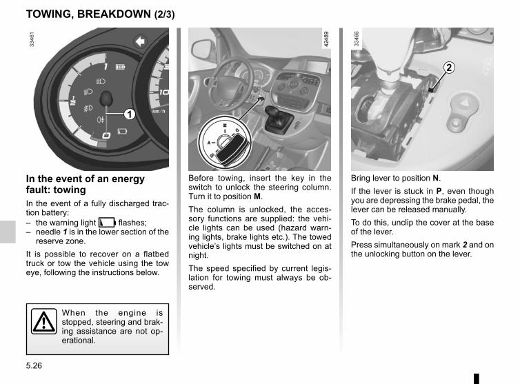
5.26
Bring lever to position N.If the lever is stuck in P, even though you are depressing the brake pedal, the lever can be released manually.To do this, unclip the cover at the base of the lever.Press simultaneously on mark 2 and on the unlocking button on the lever.
TOWING, BREAKDOWN (2/3)
In the event of an energy fault: towingIn the event of a fully discharged trac-tion battery:– the warning light Ṏ flashes;– needle 1 is in the lower section of the
reserve zone.It is possible to recover on a flatbed truck or tow the vehicle using the tow eye, following the instructions below.
When the engine is stopped, steering and brak-ing assistance are not op-erational.
Before towing, insert the key in the switch to unlock the steering column. Turn it to position M.The column is unlocked, the acces-sory functions are supplied: the vehi-cle lights can be used (hazard warn-ing lights, brake lights etc.). The towed vehicle’s lights must be switched on at night.The speed specified by current legis-lation for towing must always be ob-served.
4
1
2
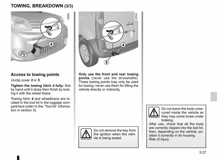
5.27
TOWING, BREAKDOWN (3/3)
Do not leave the tools unse-cured inside the vehicle as they may come loose under braking.
After use, check that all the tools are correctly clipped into the tool kit, then, depending on the vehicle, po-sition it correctly in its housing.Risk of injury.
Only use the front and rear towing points (never use the driveshafts). These towing points may only be used for towing: never use them for lifting the vehicle directly or indirectly.
53
Access to towing pointsUnclip cover 3 or 5.Tighten the towing hitch 4 fully: first by hand until it stops then finish by lock-ing it with the wheel brace.Towing hitch 4 and wheelbrace are lo-cated in the tool kit in the luggage com-partment (refer to the “Tool kit” informa-tion in section 5).
Do not remove the key from the ignition when the vehi-cle is being towed.
4 4
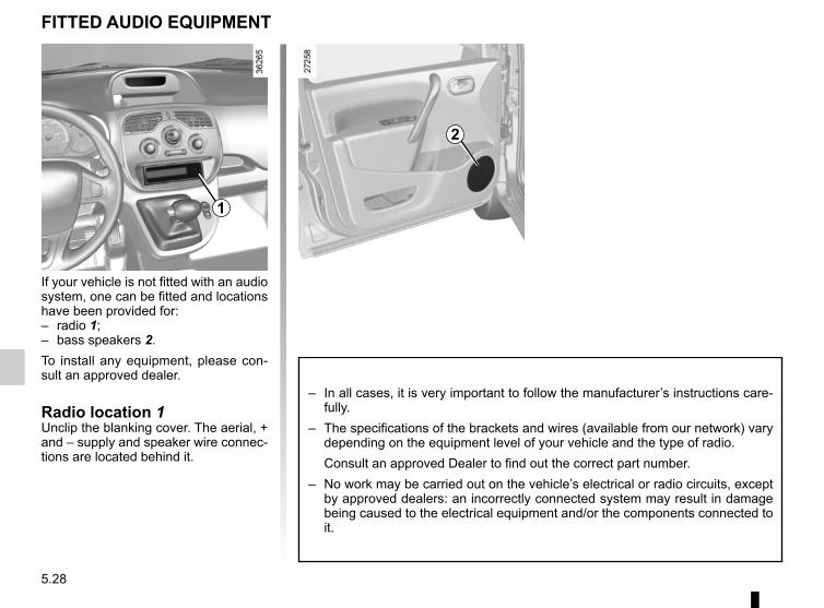
5.28
FITTED AUDIO EQUIPMENT
2
1
If your vehicle is not fitted with an audio system, one can be fitted and locations have been provided for:– radio 1;– bass speakers 2.To install any equipment, please con-sult an approved dealer.
Radio location 1Unclip the blanking cover. The aerial, + and – supply and speaker wire connec-tions are located behind it.
– In all cases, it is very important to follow the manufacturer’s instructions care-fully.
– The specifications of the brackets and wires (available from our network) vary depending on the equipment level of your vehicle and the type of radio.
Consult an approved Dealer to find out the correct part number.– No work may be carried out on the vehicle’s electrical or radio circuits, except
by approved dealers: an incorrectly connected system may result in damage being caused to the electrical equipment and/or the components connected to it.
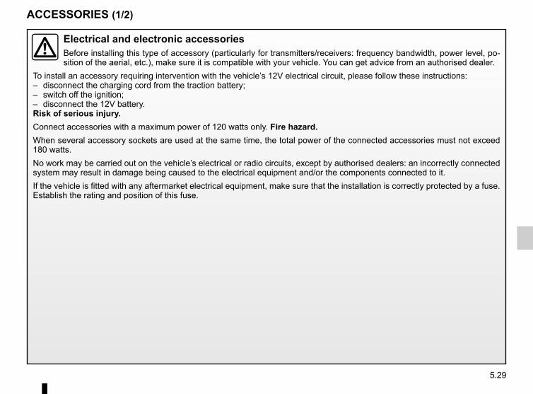
5.29
ACCESSORIES (1/2)
Electrical and electronic accessoriesBefore installing this type of accessory (particularly for transmitters/receivers: frequency bandwidth, power level, po-sition of the aerial, etc.), make sure it is compatible with your vehicle. You can get advice from an authorised dealer.
To install an accessory requiring intervention with the vehicle’s 12V electrical circuit, please follow these instructions:– disconnect the charging cord from the traction battery;– switch off the ignition;– disconnect the 12V battery.Risk of serious injury.Connect accessories with a maximum power of 120 watts only. Fire hazard.When several accessory sockets are used at the same time, the total power of the connected accessories must not exceed 180 watts.No work may be carried out on the vehicle’s electrical or radio circuits, except by authorised dealers: an incorrectly connected system may result in damage being caused to the electrical equipment and/or the components connected to it.If the vehicle is fitted with any aftermarket electrical equipment, make sure that the installation is correctly protected by a fuse. Establish the rating and position of this fuse.
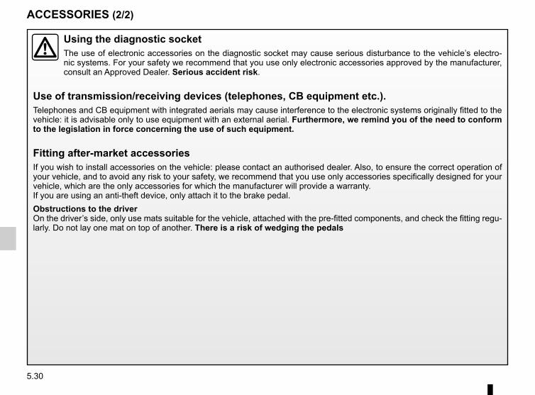
5.30
ACCESSORIES (2/2)
Using the diagnostic socketThe use of electronic accessories on the diagnostic socket may cause serious disturbance to the vehicle’s electro-nic systems. For your safety we recommend that you use only electronic accessories approved by the manufacturer, consult an Approved Dealer. Serious accident risk.
Use of transmission/receiving devices (telephones, CB equipment etc.).Telephones and CB equipment with integrated aerials may cause interference to the electronic systems originally fitted to the vehicle: it is advisable only to use equipment with an external aerial. Furthermore, we remind you of the need to conform to the legislation in force concerning the use of such equipment.
Fitting after-market accessoriesIf you wish to install accessories on the vehicle: please contact an authorised dealer. Also, to ensure the correct operation of your vehicle, and to avoid any risk to your safety, we recommend that you use only accessories specifically designed for your vehicle, which are the only accessories for which the manufacturer will provide a warranty.If you are using an anti-theft device, only attach it to the brake pedal.Obstructions to the driverOn the driver’s side, only use mats suitable for the vehicle, attached with the pre-fitted components, and check the fitting regu-larly. Do not lay one mat on top of another. There is a risk of wedging the pedals
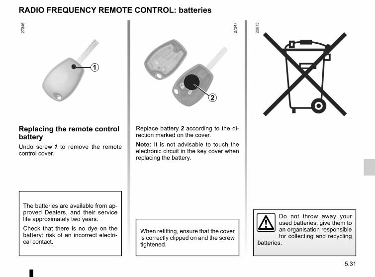
5.31
Replacing the remote control batteryUndo screw 1 to remove the remote control cover.
Replace battery 2 according to the di-rection marked on the cover.Note: It is not advisable to touch the electronic circuit in the key cover when replacing the battery.
Do not throw away your used batteries; give them to an organisation responsible for collecting and recycling
batteries.
RADIO FREQUENCY REMOTE CONTROL: batteries
1
2
When refitting, ensure that the cover is correctly clipped on and the screw tightened.
The batteries are available from ap-proved Dealers, and their service life approximately two years.Check that there is no dye on the battery: risk of an incorrect electri-cal contact.
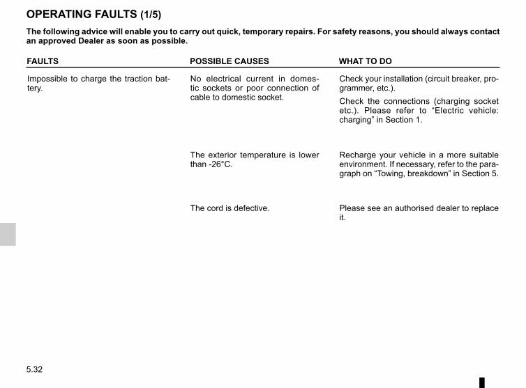
5.32
FAULTS POSSIBLE CAUSES WHAT TO DO
Impossible to charge the traction bat-tery.
No electrical current in domes-tic sockets or poor connection of cable to domestic socket.
Check your installation (circuit breaker, pro-grammer, etc.).Check the connections (charging socket etc.). Please refer to “Electric vehicle: charging” in Section 1.
The exterior temperature is lower than -26°C.
Recharge your vehicle in a more suitable environment. If necessary, refer to the para-graph on “Towing, breakdown” in Section 5.
The cord is defective. Please see an authorised dealer to replace it.
OPERATING FAULTS (1/5)The following advice will enable you to carry out quick, temporary repairs. For safety reasons, you should always contact an approved Dealer as soon as possible.
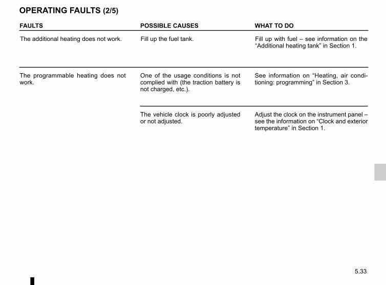
5.33
FAULTS POSSIBLE CAUSES WHAT TO DO
The additional heating does not work. Fill up the fuel tank. Fill up with fuel – see information on the “Additional heating tank” in Section 1.
The programmable heating does not work.
One of the usage conditions is not complied with (the traction battery is not charged, etc.).
See information on “Heating, air condi-tioning: programming” in Section 3.
The vehicle clock is poorly adjusted or not adjusted.
Adjust the clock on the instrument panel – see the information on “Clock and exterior temperature” in Section 1.
OPERATING FAULTS (2/5)
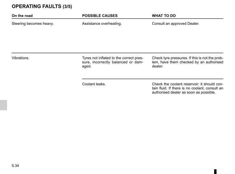
5.34
On the road POSSIBLE CAUSES WHAT TO DO
Steering becomes heavy. Assistance overheating. Consult an approved Dealer.
Vibrations. Tyres not inflated to the correct pres-sure, incorrectly balanced or dam-aged.
Check tyre pressures. If this is not the prob-lem, have them checked by an authorised dealer.
Coolant leaks. Check the coolant reservoir: it should con-tain fluid. If there is no coolant, consult an authorised dealer as soon as possible.
OPERATING FAULTS (3/5)
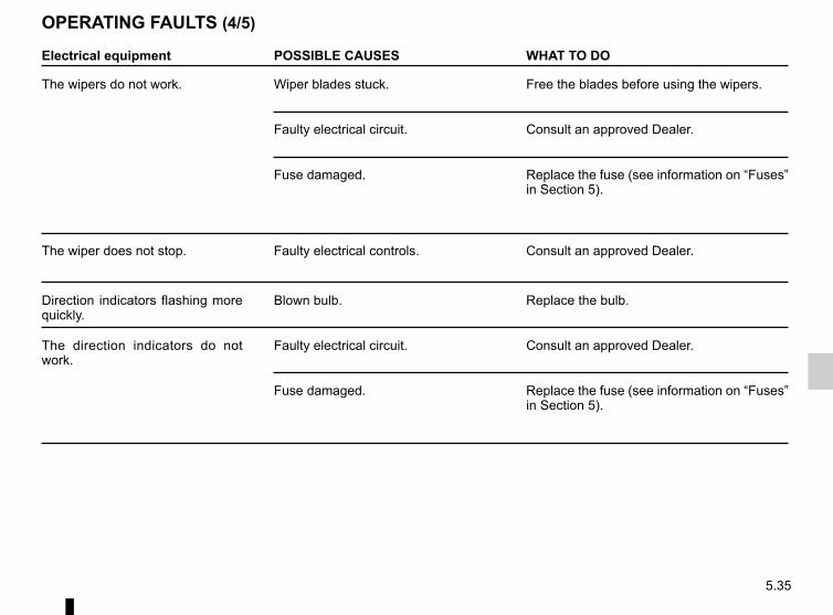
5.35
Electrical equipment POSSIBLE CAUSES WHAT TO DO
The wipers do not work. Wiper blades stuck. Free the blades before using the wipers.
Faulty electrical circuit. Consult an approved Dealer.
Fuse damaged. Replace the fuse (see information on “Fuses” in Section 5).
The wiper does not stop. Faulty electrical controls. Consult an approved Dealer.
Direction indicators flashing more quickly.
Blown bulb. Replace the bulb.
The direction indicators do not work.
Faulty electrical circuit. Consult an approved Dealer.
Fuse damaged. Replace the fuse (see information on “Fuses” in Section 5).
OPERATING FAULTS (4/5)
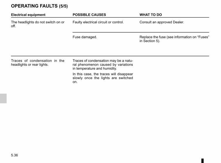
5.36
Electrical equipment POSSIBLE CAUSES WHAT TO DO
The headlights do not switch on or off.
Faulty electrical circuit or control. Consult an approved Dealer.
Fuse damaged. Replace the fuse (see information on “Fuses” in Section 5).
Traces of condensation in the headlights or rear lights.
Traces of condensation may be a natu-ral phenomenon caused by variations in temperature and humidity.In this case, the traces will disappear slowly once the lights are switched on.
OPERATING FAULTS (5/5)
6.1
Section 6: Technical specifications
Vehicle identification plates . . . . . . . . . . . . . . . . . . . . . . . . . . . . . . . . . . . . . . . . . . . . . . . . . . . . . . . . 6.2Engine identification plate . . . . . . . . . . . . . . . . . . . . . . . . . . . . . . . . . . . . . . . . . . . . . . . . . . . . . . . . . 6.3Engine specification. . . . . . . . . . . . . . . . . . . . . . . . . . . . . . . . . . . . . . . . . . . . . . . . . . . . . . . . . . . . . . 6.3Dimensions . . . . . . . . . . . . . . . . . . . . . . . . . . . . . . . . . . . . . . . . . . . . . . . . . . . . . . . . . . . . . . . . . . . . 6.4Weights . . . . . . . . . . . . . . . . . . . . . . . . . . . . . . . . . . . . . . . . . . . . . . . . . . . . . . . . . . . . . . . . . . . . . . . 6.6Replacement parts and repairs . . . . . . . . . . . . . . . . . . . . . . . . . . . . . . . . . . . . . . . . . . . . . . . . . . . . . 6.7Service sheets . . . . . . . . . . . . . . . . . . . . . . . . . . . . . . . . . . . . . . . . . . . . . . . . . . . . . . . . . . . . . . . . . . 6.8Anticorrosion check . . . . . . . . . . . . . . . . . . . . . . . . . . . . . . . . . . . . . . . . . . . . . . . . . . . . . . . . . . . . . . 6.14
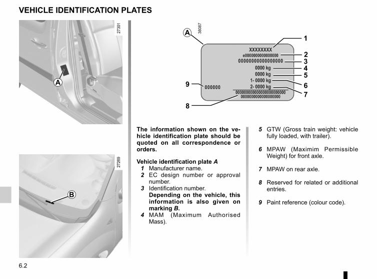
6.2
VEHICLE IDENTIFICATION PLATES
A
B
A
The information shown on the ve-hicle identification plate should be quoted on all correspondence or orders.
Vehicle identification plate A 1 Manufacturer name. 2 EC design number or approval
number. 3 Identification number.
Depending on the vehicle, this information is also given on marking B.
4 MAM (Maximum Authorised Mass).
5 GTW (Gross train weight: vehicle fully loaded, with trailer).
6 MPAW (Maximim Permissible Weight) for front axle.
7 MPAW on rear axle.
8 Reserved for related or additional entries.
9 Paint reference (colour code).
78
9 65432
1
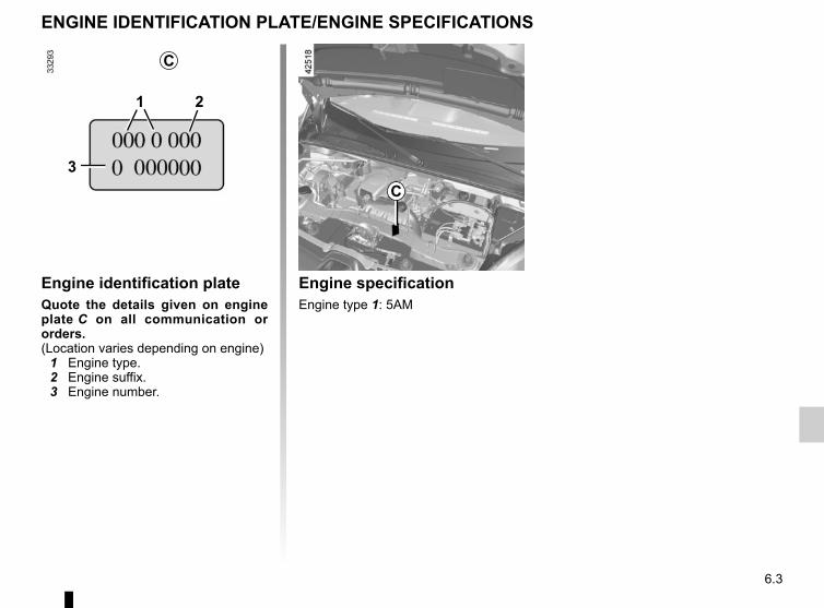
6.3
Engine identification plateQuote the details given on engine plate C on all communication or orders.(Location varies depending on engine) 1 Engine type. 2 Engine suffix. 3 Engine number.
ENGINE IDENTIFICATION PLATE/ENGINE SPECIFICATIONS
2
3
1
C
C
Engine specificationEngine type 1: 5AM
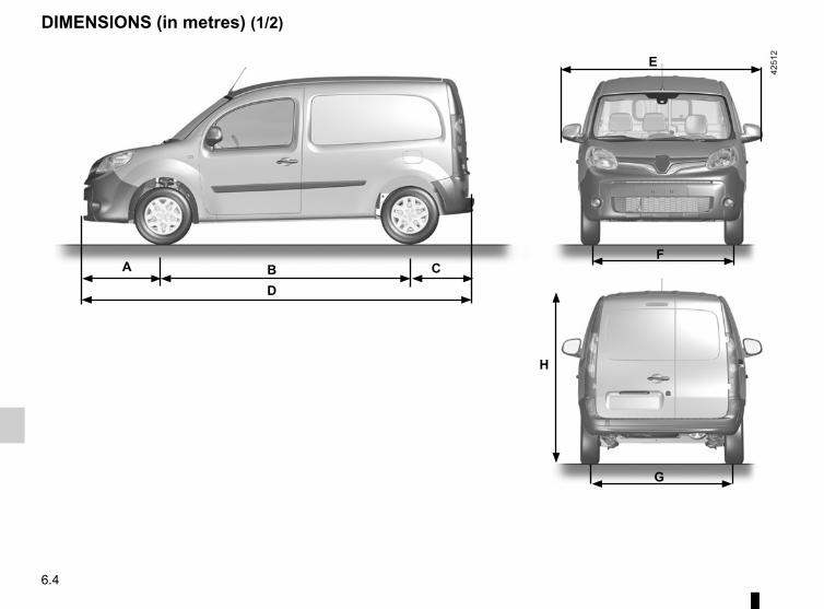
6.4
DIMENSIONS (in metres) (1/2)
H
BD
A CF
G
E
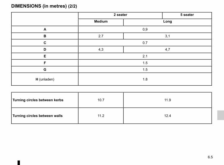
6.5
DIMENSIONS (in metres) (2/2)
2 seater 5 seater
Medium Long
A 0,9
B 2.7 3,1
C 0.7
D 4,3 4,7
E 2.1
F 1.5
G 1.5
H (unladen) 1.8
Turning circles between kerbs 10.7 11.9
Turning circles between walls 11.2 12.4
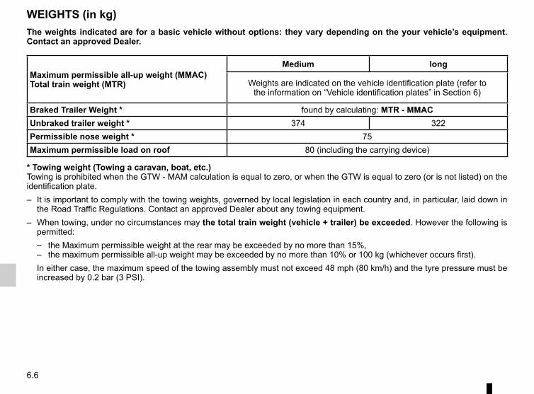
6.6
WEIGHTS (in kg)The weights indicated are for a basic vehicle without options: they vary depending on the your vehicle’s equipment. Contact an approved Dealer.
Maximum permissible all-up weight (MMAC)Total train weight (MTR)
Medium long
Weights are indicated on the vehicle identification plate (refer to the information on “Vehicle identification plates” in Section 6)
Braked Trailer Weight * found by calculating: MTR - MMACUnbraked trailer weight * 374 322Permissible nose weight * 75Maximum permissible load on roof 80 (including the carrying device)
* Towing weight (Towing a caravan, boat, etc.)Towing is prohibited when the GTW - MAM calculation is equal to zero, or when the GTW is equal to zero (or is not listed) on the identification plate.– It is important to comply with the towing weights, governed by local legislation in each country and, in particular, laid down in
the Road Traffic Regulations. Contact an approved Dealer about any towing equipment.– When towing, under no circumstances may the total train weight (vehicle + trailer) be exceeded. However the following is
permitted:– the Maximum permissible weight at the rear may be exceeded by no more than 15%,– the maximum permissible all-up weight may be exceeded by no more than 10% or 100 kg (whichever occurs first).
In either case, the maximum speed of the towing assembly must not exceed 48 mph (80 km/h) and the tyre pressure must be increased by 0.2 bar (3 PSI).
6.7
REPLACEMENT PARTS AND REPAIRSOriginal parts are based on strict specifications and are subject to highly-specialised tests. Therefore, they are of at least the same level of quality as the parts fitted originally.If you always fit genuine replacement parts to your vehicle, you will ensure that it performs well. Furthermore, repairs carried out within the manufacturer’s Network using original parts are guaranteed according to the conditions set out on the reverse of the repair order.

6.8
Date: Miles (Km): Invoice number: Comments/miscellaneousType of operation: StampService □....................................... □Anti-corrosion check:OK □ Not OK* □*See specific page
Date: Miles (Km): Invoice number: Comments/miscellaneousType of operation: StampService □....................................... □Anti-corrosion check:OK □ Not OK* □*See specific page
Date: Miles (Km): Invoice number: Comments/miscellaneousType of operation: StampService □....................................... □Anti-corrosion check:OK □ Not OK* □
*See specific page
VIN: ..................................................................................
SERVICE SHEETS (1/6)
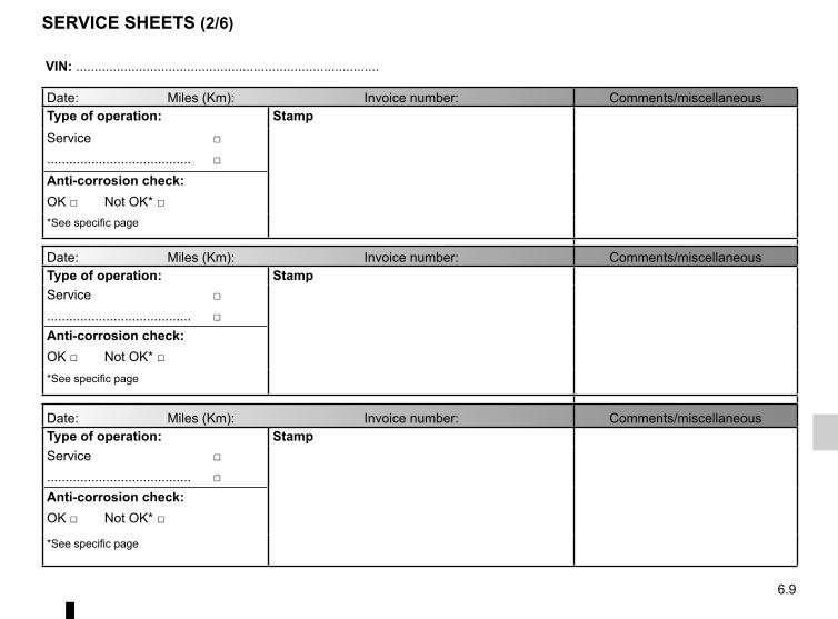
6.9
SERVICE SHEETS (2/6)
VIN: ..................................................................................
Date: Miles (Km): Invoice number: Comments/miscellaneousType of operation: StampService □....................................... □Anti-corrosion check:OK □ Not OK* □*See specific page
Date: Miles (Km): Invoice number: Comments/miscellaneousType of operation: StampService □....................................... □Anti-corrosion check:OK □ Not OK* □*See specific page
Date: Miles (Km): Invoice number: Comments/miscellaneousType of operation: StampService □....................................... □Anti-corrosion check:OK □ Not OK* □
*See specific page
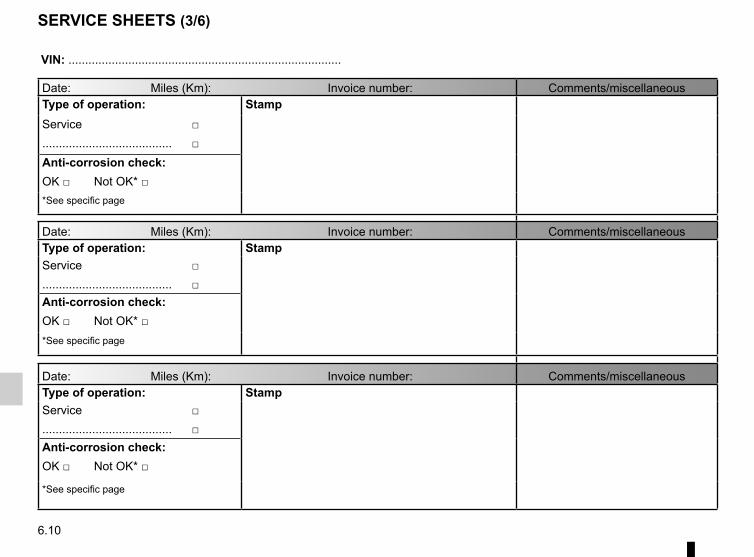
6.10
SERVICE SHEETS (3/6)
VIN: ..................................................................................
Date: Miles (Km): Invoice number: Comments/miscellaneousType of operation: StampService □....................................... □Anti-corrosion check:OK □ Not OK* □*See specific page
Date: Miles (Km): Invoice number: Comments/miscellaneousType of operation: StampService □....................................... □Anti-corrosion check:OK □ Not OK* □*See specific page
Date: Miles (Km): Invoice number: Comments/miscellaneousType of operation: StampService □....................................... □Anti-corrosion check:OK □ Not OK* □
*See specific page

6.11
SERVICE SHEETS (4/6)
VIN: ..................................................................................
Date: Miles (Km): Invoice number: Comments/miscellaneousType of operation: StampService □....................................... □Anti-corrosion check:OK □ Not OK* □*See specific page
Date: Miles (Km): Invoice number: Comments/miscellaneousType of operation: StampService □....................................... □Anti-corrosion check:OK □ Not OK* □*See specific page
Date: Miles (Km): Invoice number: Comments/miscellaneousType of operation: StampService □....................................... □Anti-corrosion check:OK □ Not OK* □
*See specific page

6.12
SERVICE SHEETS (5/6)
VIN: ..................................................................................
Date: Miles (Km): Invoice number: Comments/miscellaneousType of operation: StampService □....................................... □Anti-corrosion check:OK □ Not OK* □*See specific page
Date: Miles (Km): Invoice number: Comments/miscellaneousType of operation: StampService □....................................... □Anti-corrosion check:OK □ Not OK* □*See specific page
Date: Miles (Km): Invoice number: Comments/miscellaneousType of operation: StampService □....................................... □Anti-corrosion check:OK □ Not OK* □
*See specific page

6.13
VIN: ..................................................................................
Date: Miles (Km): Invoice number: Comments/miscellaneousType of operation: StampService □....................................... □Anti-corrosion check:OK □ Not OK* □*See specific page
Date: Miles (Km): Invoice number: Comments/miscellaneousType of operation: StampService □....................................... □Anti-corrosion check:OK □ Not OK* □*See specific page
Date: Miles (Km): Invoice number: Comments/miscellaneousType of operation: StampService □....................................... □Anti-corrosion check:OK □ Not OK* □
*See specific page
SERVICE SHEETS (6/6)

6.14
ANTICORROSION CHECK (1/5)
If the continuation of the warranty is subject to repair, it is indicated below.
VIN: ..........................................................
Corrosion repair operation to be carried out:
Stamp
Date of repair:
Repair to be carried out: Stamp
Date of repair:
Repair to be carried out: Stamp
Date of repair:

6.15
ANTICORROSION CHECK (2/5)
If the continuation of the warranty is subject to repair, it is indicated below.
VIN: ..........................................................
Corrosion repair operation to be carried out:
Stamp
Date of repair:
Repair to be carried out: Stamp
Date of repair:
Repair to be carried out: Stamp
Date of repair:

6.16
ANTICORROSION CHECK (3/5)
If the continuation of the warranty is subject to repair, it is indicated below.
VIN: ..........................................................
Corrosion repair operation to be carried out:
Stamp
Date of repair:
Repair to be carried out: Stamp
Date of repair:
Repair to be carried out: Stamp
Date of repair:
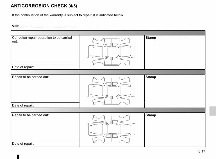
6.17
ANTICORROSION CHECK (4/5)
If the continuation of the warranty is subject to repair, it is indicated below.
VIN: ..........................................................
Corrosion repair operation to be carried out:
Stamp
Date of repair:
Repair to be carried out: Stamp
Date of repair:
Repair to be carried out: Stamp
Date of repair:

6.18
ANTICORROSION CHECK (5/5)
If the continuation of the warranty is subject to repair, it is indicated below.
VIN: ..........................................................
Corrosion repair operation to be carried out:
Stamp
Date of repair:
Repair to be carried out: Stamp
Date of repair:
Repair to be carried out: Stamp
Date of repair:
7.1
ALPHABETICAL INDEX (1/5)AABS .......................................................................2.15 → 2.17accessories............................................................. 5.29 – 5.30accessories socket ............................................................ 3.18additional heating fuel........................................................ 1.93additional heating tank....................................................... 1.93additional methods of restraint .......................................... 1.45additional heating ................................................... 3.10 – 3.11
additional heating fuel tank .......................................... 1.93additional tank capacity ..................................................... 1.93additional tank filling .......................................................... 1.93air bag....................................................................1.41 → 1.45
activating the front passenger air bags ............1.58 → 1.60deactivating the front passenger air bags ........1.58 → 1.60
air conditioning ......................................3.4 → 3.7, 3.12 – 3.13air vents ...................................................................... 3.2 – 3.3anti-corrosion check ..............................................6.14 → 6.18anti-corrosion protection .................................................... 4.10anti-lock braking system: ABS ...............................2.15 → 2.17ashtrays ............................................................................. 3.18audible and visual signals.................................................. 1.83
B12 volt battery
maintenance ......................................................... 4.6 – 4.712 volt battery ............................................1.2 → 1.7, 4.6 – 4.7battery (remote control) ..................................................... 5.31bonnet......................................................................... 4.2 – 4.3brake fluid ............................................................................ 4.5brake lights
changing bulbs .................................................. 5.16 – 5.17bulbs
changing ..........................................................5.13 → 5.20
Ccentral door locking ........................................................... 1.21
changing a bulb .................................5.13 → 5.15, 5.19 – 5.20changing a wheel................................................................. 5.8changing gear ............................................................. 2.4 – 2.5charge meter ....................................................1.70, 2.6 → 2.8charging cord ..................................................1.9 → 1.16, 1.19charging flap ............................................................1.8 → 1.16charging socket .....................................1.2 → 1.7, 1.9 → 1.16child minder mirror ............................................................. 3.16child restraint/seat .............................1.46 – 1.47, 1.49 → 1.60child safety.....1.17, 1.19, 1.23, 1.46 – 1.47, 1.49 → 1.60, 3.17child seats..........................................1.46 – 1.47, 1.49 → 1.57children ................................................................... 1.46 – 1.47cigar lighter ........................................................................ 3.18cleaning:
inside the vehicle .............................................. 4.13 – 4.14clock .................................................................................. 1.81closing the doors ...................................................1.22 → 1.25connected services .............................................................. 1.3control instruments ................................................1.69 → 1.77controls ..................................................................1.62 → 1.65coolant ................................................................................. 4.4courtesy light ..................................................................... 3.15courtesy mirrors ................................................................. 3.16cruise control .........................................................2.21 → 2.24
Ddashboard..............................................................1.62 → 1.65deadlocking the doors ....................................................... 1.19de-icing ................................................................................ 3.5dimensions ................................................................. 6.4 – 6.5display ...................................................................1.66 → 1.71doors......................................................................1.22 → 1.28driver’s position .....................................................1.62 → 1.68driving .................................................. 2.4 → 2.9, 2.11 → 2.26driving position
settings ............................................................1.37 → 1.40
7.2
ALPHABETICAL INDEX (2/5)driving recommendations ........................................... 2.6 – 2.7
E»ECO» mode function ......................................................... 2.8ECO driving ................................................................ 2.6 – 2.7ECO mode ........................................................................... 2.6»400 volt» electrical circuit ........................................1.2 → 1.8electric vehicle
vehicle range .......................................................2.6 → 2.8batteries ......................................................................... 1.4noise .............................................................................. 1.6charge ................................................................1.9 → 1.16driving ....................................................1.6, 2.4, 2.6 → 2.8important recommendations ................................. 1.8, 1.12
electric windows ................................................................ 3.17electrical installation .......................................................... 1.12electronic stability control: ESC .............................2.15 → 2.17emergency brake assist.........................................2.15 → 2.17emergency braking ................................................2.15 → 2.17emergency spare wheel ...................................................... 5.2energy
recovery ....................................................................... 1.70saving ............................................................ 2.6, 2.8 – 2.9consumption ..................................................... 1.69 – 1.70charge ................................................................1.9 → 1.16range ..................................................................... 2.6 – 2.7
energy saving ............................................................2.6 → 2.9energy consumption ..................................................2.6 → 2.9energy recovery ................................................................... 2.6engine specifications ........................................................... 6.3environment ....................................................................... 2.10ESC: electronic stability control .............................2.15 → 2.17external temperature ......................................................... 1.81
Ffaults
operating faults ................................................5.32 → 5.36fitting a radio ...................................................................... 5.28fittings ....................................................................3.19 → 3.21fog lights ................................................................... 1.87, 5.15front lights
changing bulbs .................................................. 5.13 – 5.14front passenger air bag deactivation .....................1.58 → 1.60front seat adjustment .............................................. 1.32 – 1.33front seats
adjustment ........................................................ 1.32 – 1.33fuel
capacity ........................................................................ 1.93filling ............................................................................. 1.93grade ............................................................................ 1.93
fuel filler cap ...................................................................... 1.93fuses ....................................................................... 5.21 – 5.22
Ggear lever.................................................................... 2.4 – 2.5glove box ........................................................................... 3.19
Hhandbrake............................................................................ 2.5hazard warning lights signal .............................................. 1.83headlight beam adjustment .................................... 1.88 – 1.89headrest........................................................1.29 → 1.31, 3.22heated seats ........................................................... 1.32 – 1.33heating and air conditioning system ....................... 3.12 – 3.13heating, air conditioning: programming ........ 2.7, 2.9, 3.8 – 3.9heating system ........................................................3.4 → 3.13horn ................................................................................... 1.83horn:
flash ............................................................................. 1.83sounding the horn ........................................................ 1.83
7.3
ALPHABETICAL INDEX (3/5)hubcap tool .......................................................................... 5.6
Iindicators ......................................................... 1.83, 5.14, 5.19indicators:
direction indicators .............................................. 5.14, 5.19instrument panel ..............................................1.66 → 1.71
instrument panel ....................................................1.66 → 1.80instrument panel messages...................................1.72 → 1.80interior lighting:
changing bulbs ............................................................. 5.20interior trim
maintenance ..................................................... 4.13 – 4.14Isofix ......................................................................1.49 → 1.57
Jjack ............................................................................... 5.6, 5.8
Llevels:
brake fluid ...................................................................... 4.5coolant ........................................................................... 4.4windscreen washer reservoir ......................................... 4.5
lifting the vehiclechanging a wheel .................................................. 5.8 – 5.9
lighting:interior .......................................................................... 3.15
lightsadjustment ........................................................ 1.88 – 1.89changing bulbs .................................................. 5.13 – 5.14fog lights ...................................................................... 5.15front ................................................................... 5.13 – 5.14
lights:brake lights .................................................................. 5.16dipped beam headlights ............................. 1.66, 1.85, 5.13direction indicator lights ............................................... 1.66
direction indicators ..................................... 1.66, 1.83, 5.16fog lights .................................................... 1.66, 1.87, 5.15hazard warning ............................................................ 1.83main beam headlights .............................. 1.66, 1.85 – 1.86number plate lights ...................................................... 5.18reversing lights ............................................................. 5.16side lights ..................................................................... 1.85
lights-on warning buzzer........................................... 1.22, 1.86locking the doors ........................................... 1.21, 1.26 – 1.27
Mmaintenance:
bodywork .........................................................4.10 → 4.12interior trim ........................................................ 4.13 – 4.14mechanical .........................................4.2 – 4.3, 6.8 → 6.13
map reading lights ............................................................. 3.15methods of restraint in addition to the front seat belts ..............1.41 → 1.43methods of restraint in addition to the seat belts ...1.41 → 1.45multimedia (equipment) ..................................................... 3.14multimedia equipment .............................................. 3.14, 5.28
Nnavigation .......................................................................... 3.14navigation system .............................................................. 3.14
Oopening the doors ..................................................1.22 → 1.25operating faults ................................1.66 → 1.68, 5.32 → 5.36
Ppaintwork
maintenance ....................................................4.10 → 4.12reference ........................................................................ 6.2
parking distance control.......................................... 2.25 – 2.26partition .............................................................................. 1.36
7.4
ALPHABETICAL INDEX (4/5)pedestrian warning system ................................................ 1.84power-assisted steering..................................................... 1.61practical advice ..........................................................2.6 → 2.9presentation of the electric vehicle
batteries ...............................................................1.2 → 1.7pretensioners ..................................................................... 1.41puncture........................................................................ 5.6, 5.8
Rradio.......................................................................... 3.14, 5.28radio frequency remote control/key
use ...................................................................... 1.17, 1.19range of the traction battery........................................ 2.6 – 2.7rear bench seat....................................................... 3.23 – 3.24rear lights
changing bulbs .................................................5.16 → 5.18rear screen
demisting ....................................................................... 3.2rear seats
functions ........................................................... 3.23 – 3.24rear view camera .................................................... 2.27 – 2.28rear view mirrors ................................................................ 1.82remote control door locking
batteries ....................................................................... 5.31remote control electric door locking .......................... 1.17, 1.19RENAULT ANTI-INTRUDER DEVICE (RAID) ................... 1.28replacement parts ................................................................ 6.7reverse gear
selecting ................................................................ 2.4 – 2.5reversing sensor ..................................................... 2.25 – 2.26
Sseat belts ...............................................................1.37 → 1.45see-me-home lighting ........................................................ 1.86service sheets..........................................................6.8 → 6.13
side indicator lightschanging bulbs ............................................................. 5.19
side protection devices ...................................................... 1.44signals and lights ...................................................1.85 → 1.87speed control .............................................................. 2.4 – 2.5speed limiter ..........................................................2.18 → 2.20steering wheel
adjustment ................................................................... 1.61storage compartment.............................................3.19 → 3.21storage compartments ...........................................3.19 → 3.21sun visor ................................................................... 3.16, 3.21
Ttailgate ................................................ 1.24 – 1.25, 3.25 – 3.26tanks and reservoirs
brake fluid ...................................................................... 4.5coolant ........................................................................... 4.4
tanks and reservoirs:windscreen washer ........................................................ 4.5
technical specifications .......................................6.2, 6.4 → 6.7temperature regulation ........................................... 3.12 – 3.13tool kit .................................................................................. 5.6towing
in the event of energy failure ...........................5.25 → 5.27breakdown .......................................................5.25 → 5.27
towing equipmentfitting ............................................................................ 3.26
towing hitch...................................................... 5.6, 5.26 – 5.27towing rings ...........................................................1.49 → 1.51traction battery
charge ............................................................................ 1.9traction battery ...........................................................1.2 → 1.8traction battery charge ....................................1.9 → 1.16, 1.19traction control .......................................................2.15 → 2.17transporting children ..........................1.46 – 1.47, 1.49 → 1.60
7.5
ALPHABETICAL INDEX (5/5)transporting objects
in the luggage compartment ............................. 3.25 – 3.26trims ..................................................................................... 5.7trip computer and warning system...1.66 → 1.68, 1.74 → 1.80tyre inflation kit...........................................................5.3 → 5.5tyre pressure...................................................2.11 → 2.14, 4.8tyre pressure loss warning.....................................2.11 → 2.14tyre pressures ........................................4.8 – 4.9, 5.10 → 5.12tyres .......................................... 2.11 → 2.14, 4.8, 5.10 → 5.12
Uunlocking the doors ................................................ 1.26 – 1.27
Vvehicle identification ............................................................ 6.2vehicle identification plates .................................................. 6.2vehicle range .............................................................2.6 → 2.9ventilation ..............................................3.2 → 3.9, 3.12 – 3.13
Wwarning lights............................1.66 → 1.68, 1.72 – 1.73, 1.79washing .................................................................4.10 → 4.12weights ................................................................................ 6.6wheelbrace .......................................................................... 5.6wheels (safety) .................................................................. 5.10windscreen de-icing/demisting ............................................ 3.5windscreen washer .........................................1.90 → 1.92, 4.5windscreen washer/wiper
replacing blades ................................................ 5.23 – 5.24wiper blades ........................................................... 5.23 – 5.24wipers ....................................................................1.90 → 1.92

7.6


à999109590Ròêúä 9ERENAULT S.A.S. SOCIÉTÉ PAR ACTIONS SIMPLIFIÉE AU CAPITAL DE 533 941 113 € / 13-15, QUAI LE GALLO 92100 BOULOGNE-BILLANCOURT R.C.S. NANTERRE 780 129 987 — SIRET 780 129 987 03591 / TÉL. : 0810 40 50 60
NU 1063-10 – 99 91 095 90R – 01/2018 – Edition anglaise