Embed Size (px)
Citation preview
T
Na
b
c
a
ARAA
KBTGPC
C
1
pfc[c
1d
Renewable and Sustainable Energy Reviews 16 (2012) 1801– 1816
Contents lists available at SciVerse ScienceDirect
Renewable and Sustainable Energy Reviews
j ourna l h o mepage: www.elsev ier .com/ locate / rser
hermo chemical conversion of biomass – Eco friendly energy routes
.L. Panwara,∗, Richa Kotharib, V.V. Tyagic
Department of Renewable Energy Sources, College of Technology and Engineering, Maharana Pratap University of Agriculture and Technology, Udaipur 313 001, IndiaSchool of Environmental Sciences, Babasaheb Bhimrao Ambedkar University, Lucknow, U.P. 226025, IndiaCentre of Research UMPEDAC, Level 4, Engineering Tower, Faculty of Engineering, University of Malaya, Kuala Lumpur 50603, Malaysia
r t i c l e i n f o
rticle history:eceived 25 April 2011ccepted 6 January 2012vailable online 18 February 2012
a b s t r a c t
Biomass is indirect source of solar energy and it is renewable in nature. It is one of the most impor-tant energy source in near future because of its extensive spread availability and promising potential toreduce global warming. Thermo chemical conversion of biomass yield variety of solid, liquid and gaseousfuels and have equal importance both at industrial and ecological point of views. Present review gives
eywords:iomasshermo chemicalasification
holistic view of various thermo-chemical conversion route of biomass. Gasification technology, pyroly-sis options and scope of potential by product from there routes like hydrogen and charcoal productioncomprehensively reviewed with present context.
© 2012 Elsevier Ltd. All rights reserved.
yrolysisarbonization
ontents
1. Introduction . . . . . . . . . . . . . . . . . . . . . . . . . . . . . . . . . . . . . . . . . . . . . . . . . . . . . . . . . . . . . . . . . . . . . . . . . . . . . . . . . . . . . . . . . . . . . . . . . . . . . . . . . . . . . . . . . . . . . . . . . . . . . . . . . . . . . . . . . . 18012. Biomass classification . . . . . . . . . . . . . . . . . . . . . . . . . . . . . . . . . . . . . . . . . . . . . . . . . . . . . . . . . . . . . . . . . . . . . . . . . . . . . . . . . . . . . . . . . . . . . . . . . . . . . . . . . . . . . . . . . . . . . . . . . . . . . . . . 18023. Type of thermo chemical conversion route of biomass . . . . . . . . . . . . . . . . . . . . . . . . . . . . . . . . . . . . . . . . . . . . . . . . . . . . . . . . . . . . . . . . . . . . . . . . . . . . . . . . . . . . . . . . . . . . . 1802
3.1. Gasification . . . . . . . . . . . . . . . . . . . . . . . . . . . . . . . . . . . . . . . . . . . . . . . . . . . . . . . . . . . . . . . . . . . . . . . . . . . . . . . . . . . . . . . . . . . . . . . . . . . . . . . . . . . . . . . . . . . . . . . . . . . . . . . . . . . 18023.1.1. Classification of biomass gasifier’s . . . . . . . . . . . . . . . . . . . . . . . . . . . . . . . . . . . . . . . . . . . . . . . . . . . . . . . . . . . . . . . . . . . . . . . . . . . . . . . . . . . . . . . . . . . . . . . . . 18023.1.2. Design of gasifier . . . . . . . . . . . . . . . . . . . . . . . . . . . . . . . . . . . . . . . . . . . . . . . . . . . . . . . . . . . . . . . . . . . . . . . . . . . . . . . . . . . . . . . . . . . . . . . . . . . . . . . . . . . . . . . . . . . 18043.1.3. Case studies . . . . . . . . . . . . . . . . . . . . . . . . . . . . . . . . . . . . . . . . . . . . . . . . . . . . . . . . . . . . . . . . . . . . . . . . . . . . . . . . . . . . . . . . . . . . . . . . . . . . . . . . . . . . . . . . . . . . . . . . . 1804
3.2. Pyrolysis of biomass . . . . . . . . . . . . . . . . . . . . . . . . . . . . . . . . . . . . . . . . . . . . . . . . . . . . . . . . . . . . . . . . . . . . . . . . . . . . . . . . . . . . . . . . . . . . . . . . . . . . . . . . . . . . . . . . . . . . . . . . . . 18083.2.1. Classification of pyrolysis process . . . . . . . . . . . . . . . . . . . . . . . . . . . . . . . . . . . . . . . . . . . . . . . . . . . . . . . . . . . . . . . . . . . . . . . . . . . . . . . . . . . . . . . . . . . . . . . . . . 18083.2.2. Case studies . . . . . . . . . . . . . . . . . . . . . . . . . . . . . . . . . . . . . . . . . . . . . . . . . . . . . . . . . . . . . . . . . . . . . . . . . . . . . . . . . . . . . . . . . . . . . . . . . . . . . . . . . . . . . . . . . . . . . . . . . 18093.2.3. Effect of temperature on feedstock material in pyrolysis process . . . . . . . . . . . . . . . . . . . . . . . . . . . . . . . . . . . . . . . . . . . . . . . . . . . . . . . . . . . . . . . . . 18103.2.4. Potential byproducts: hydrogen . . . . . . . . . . . . . . . . . . . . . . . . . . . . . . . . . . . . . . . . . . . . . . . . . . . . . . . . . . . . . . . . . . . . . . . . . . . . . . . . . . . . . . . . . . . . . . . . . . . . 1811
3.3. Carbonization . . . . . . . . . . . . . . . . . . . . . . . . . . . . . . . . . . . . . . . . . . . . . . . . . . . . . . . . . . . . . . . . . . . . . . . . . . . . . . . . . . . . . . . . . . . . . . . . . . . . . . . . . . . . . . . . . . . . . . . . . . . . . . . . . 18123.3.1. The stages in charcoal formation . . . . . . . . . . . . . . . . . . . . . . . . . . . . . . . . . . . . . . . . . . . . . . . . . . . . . . . . . . . . . . . . . . . . . . . . . . . . . . . . . . . . . . . . . . . . . . . . . . . 18123.3.2. Case studies . . . . . . . . . . . . . . . . . . . . . . . . . . . . . . . . . . . . . . . . . . . . . . . . . . . . . . . . . . . . . . . . . . . . . . . . . . . . . . . . . . . . . . . . . . . . . . . . . . . . . . . . . . . . . . . . . . . . . . . . . 1812
4. Conclusions . . . . . . . . . . . . . . . . . . . . . . . . . . . . . . . . . . . . . . . . . . . . . . . . . . . . . . . . . . . . . . . . . . . . . . . . . . . . . . . . . . . . . . . . . . . . . . . . . . . . . . . . . . . . . . . . . . . . . . . . . . . . . . . . . . . . . . . . . . 1814References . . . . . . . . . . . . . . . . . . . . . . . . . . . . . . . . . . . . . . . . . . . . . . . . . . . . . . . . . . . . . . . . . . . . . . . . . . . . . . . . . . . . . . . . . . . . . . . . . . . . . . . . . . . . . . . . . . . . . . . . . . . . . . . . . . . . . . . . . . . 1814
. Introduction
Biomass store solar energy in the chemical form and it is mostrecious and versatile resources on earth. Biomass, unlike fossiluels, is a renewable energy resource that is available where the
land and aquatic environments. Biomass includes by product andresidue of crop farming and processing industries such as straw,husk, cobs, stalks, leaves, bark, fruits, cutting vines, in additionto animal refuses and plant products used in agro-industrial pro-cessing such as grains, bean, flower and some special products
limatic conditions are favorable for plant growth and production1]. The term biomass is used for all organic materials which areombustible in nature, mainly plant and animal origin present in
∗ Corresponding author. Tel.: +91 294 2471068; fax: +91 294 2471056.E-mail address: [email protected] (N.L. Panwar).
364-0321/$ – see front matter © 2012 Elsevier Ltd. All rights reserved.oi:10.1016/j.rser.2012.01.024
such as cassava, seaweeds [2–4]. Agricultural wastes particularlycontain a high amount of organic constituents (cellulose, hemicel-lulose, lignin and minor amounts of other organics) and possesshigh energy content [5,6].
Biomass is considered carbon neutral, because the amount ofcarbon it can release is equivalent to the amount it absorbed duringits life time. There is no net increase of carbon to the environment
1 ainable Energy Reviews 16 (2012) 1801– 1816
iTao
eibIr[
phagtc
2
rcc
(
(
3
cmla
3
wiT8cicaotortCrp
3
tF
Table 1Basic gasification reactions [17].
Reaction Heating value (kJ/mol)
2C + O2 ↔ 2CO +246.4C + O2 ↔ CO2 +408.8CH4 + H2O ↔ CO + 3H2 −206
Fluidized bed gasifier: Fluidized bed (FB) gasification hasbeen used extensively for coal gasification from many years, itsadvantage over fixed bed gasifiers being the uniform temperaturedistribution achieved in the gasification zone [22]. In this type
Table 2Constituents of producer gas [18].
Compounds Symbol Gas (vol.%) Dry gas (vol.%)
Carbon monoxide CO 21.0 22.1Carbon dioxide CO2 9.7 10.2Hydrogen H2 14.5 15.2Water vapour H2O 4.8 –Methane CH4 1.6 1.7Nitrogen N2 48.4 50.8
802 N.L. Panwar et al. / Renewable and Sust
n the long term when combusting the lignocellulosic materials.herefore, we can say that biomass is a renewable source of energynd can play vital role in responding to concerns over the protectionf the environment and the security of energy supply [7,8].
Renewable technologies are considered as clean sources ofnergy and optimal use of these resources minimize environmentalmpacts, produce minimum secondary wastes and are sustainableased on current and future economic and social societal needs [9].n the present context, it is considered a fuel source to partiallyeplace the use of fossil fuels through thermo-chemical processes10].
In this review paper an attempt has been made to identify theossible thermo chemical conversion routes of biomass. Energyarvested by means of this route is integrated with industrialpplications to meeting their energy need. Possibilities of biomassasification at industrial level, pyrolysis oil and their scope forransportation, applications of hydrogen in fuel cell, scope of char-oal production has also comprehensively presented in this paper.
. Biomass classification
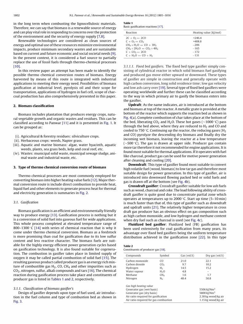
Biomass includes plantation that produces energy crops, natu-al vegetable growth and organic wastes and residues. This can belassified according to Panwar [11] and it is presented in Fig. 1. Itan be grouped as:
(i). Agricultural & forestry residues: silviculture crops.(ii). Herbaceous crops: weeds, Napier grass.iii). Aquatic and marine biomass: algae, water hyacinth, aquatic
weeds, plants, sea grass beds, kelp and coral reef, etc.iv). Wastes: municipal solid waste, municipal sewage sludge, ani-
mal waste and industrial waste, etc.
. Type of thermo chemical conversion route of biomass
Thermo chemical processes are most commonly employed foronverting biomass into higher heating value fuels [12]. Major ther-al conversion route is include direct combustion to provide heat,
iquid fuel and other elements to generate process heat for thermalnd electricity generation is summaries in Fig. 2.
.1. Gasification
Biomass gasification is an efficient and environmentally friendlyay to produce energy [13]. Gasification process is nothing but it
s a conversion of solid fuel into gaseous fuel for wide applications.his whole process completed at elevated temperature range of00–1300 ◦C [14] with series of chemical reaction that is why itome under thermo chemical conversion. Biomass as a feedstocks more promising than coal for gasification due to its low sulfurontent and less reactive character. The biomass fuels are suit-ble for the highly energy efficient power generation cycles basedn gasification technology. It is also found suitable for cogenera-ion. The combustion in gasifier takes place in limited supply ofxygen it may be called partial combustion of solid fuel [15]. Theesulting gaseous product called producer gas is an energy rich mix-ure of combustible gas H2, CO, CH4 and other impurities such asO2, nitrogen, sulfur, alkali compounds and tars [16]. The chemicaleaction during gasification process take place and constituents ofroducer gas is listed in Tables 1 and 2, respectively.
.1.1. Classification of biomass gasifier’sDesign of gasifier depends upon type of fuel used, air introduc-
ion in the fuel column and type of combustion bed as shown inig. 3.
CH4 + 2H2O ↔ CO2 + 4H2 −165C + CO2 ↔ 2CO −172C + H2O ↔ CO + H2 −131
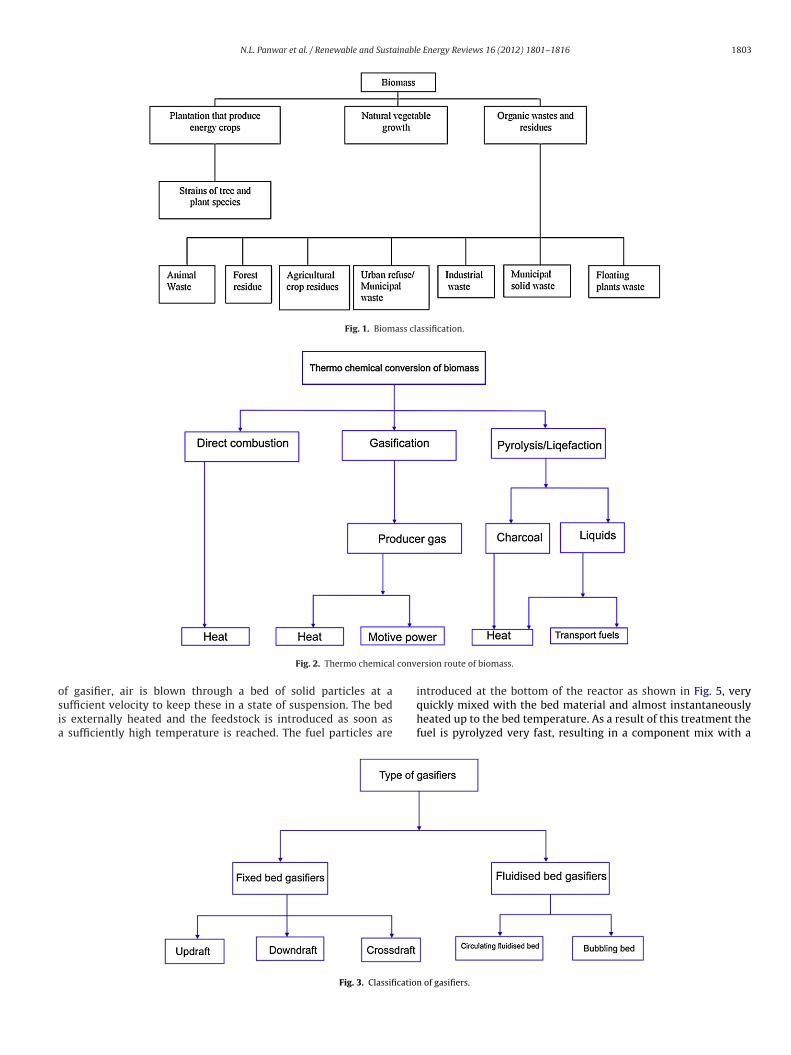
3.1.1.1. Fixed bed gasifiers. The fixed bed type gasifier simply con-sisting of cylindrical reactor in which solid biomass fuel gasifyingand produced gas move either upward or downward. These typesof gasifier are simple in construction and generally operate withhigh carbon conversion, long solid residence time; low gas velocityand low ash carry over [19]. Several type of fixed bed gasifiers wereoperating worldwide and further these can be classified accordingto the way in which primary air to gasify the biomass enters intothe gasifier.
Updraft: As the name indicates, air is introduced at the bottomand biomass at top of the reactor. A metallic grate is provided at thebottom of the reactor which supports the reaction bed as shown inFig. 4(a). Complete combustion of char takes place at the bottom ofthe bed, liberating CO2 and H2O. These hot gases (∼1000 ◦C) passthrough the bed above, where they are reduced to H2 and CO andcooled to 750 ◦C. Continuing up the reactor, the reducing gases (H2and CO) pyrolyze the descending dry biomass and finally dry theincoming wet biomass, leaving the reactor at a low temperature(∼500 ◦C). The gas is drawn at upper side. Producer gas containmore tar therefore it not recommended for engine applications. It isfound most suitable for thermal applications. If it operates with fuellike charcoal, product gas can be used for motive power generationafter cleaning and cooling [20].
Downdraft: This type of gasifier found most suitable to converthigh volatile fuel (wood, biomass) to low tar gas and therefore mostsuitable design for power generation. In this type of gasifier, air isintroduced into downward flowing packed bed or solid fuels andgas is drawn off at the bottom (see Fig. 4b).
Crossdraft gasifier: Crossdraft gasifier suitable for low ash fuelssuch as wood, charcoal and coke. The load following ability of cross-draft gasifier is quite good due to concentrate partial zone whichoperates at temperatures up to 2000 ◦C. Start up time (5–10 min)is much faster than that of, this type of gasifier such as downdraftand updraft units [21]. The relatively higher temperature in crossdraft gas producer has an obvious effect on gas composition suchas high carbon monoxide, and low hydrogen and methane contentwhen dry fuel such as charcoal is used (see Fig. 4c).
Gas high heating valueGenerator gas (wet basis) 5506 kJ/Nm3
Generator gas (dry basis) 5800 kJ/Nm3
Air ratio required for gasification 2.38 kg wood/kg airAir ratio required for gas combustion 1.15 kg wood/kg air
N.L. Panwar et al. / Renewable and Sustainable Energy Reviews 16 (2012) 1801– 1816 1803
Fig. 1. Biomass classification.
conv
osia
Fig. 2. Thermo chemical
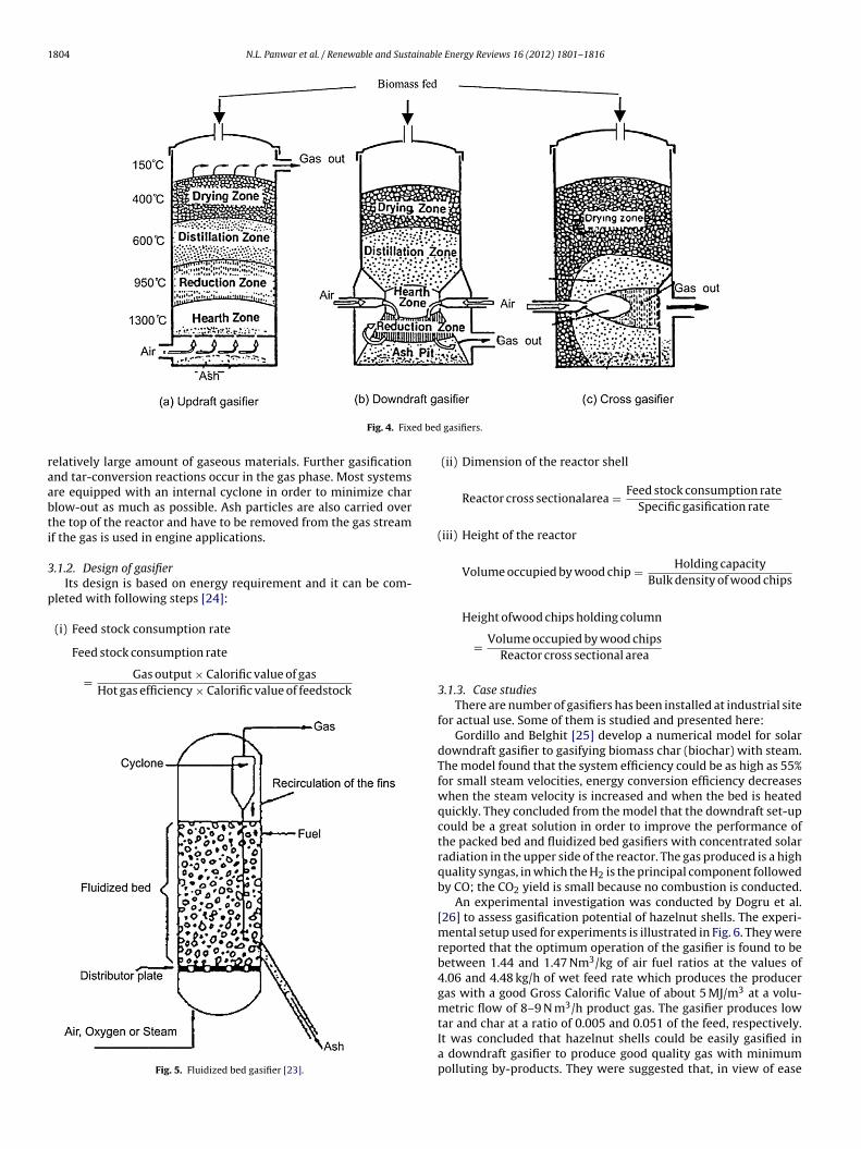
f gasifier, air is blown through a bed of solid particles at aufficient velocity to keep these in a state of suspension. The beds externally heated and the feedstock is introduced as soon as
sufficiently high temperature is reached. The fuel particles are
Fig. 3. Classificatio
ersion route of biomass.
introduced at the bottom of the reactor as shown in Fig. 5, veryquickly mixed with the bed material and almost instantaneouslyheated up to the bed temperature. As a result of this treatment thefuel is pyrolyzed very fast, resulting in a component mix with a
n of gasifiers.
1804 N.L. Panwar et al. / Renewable and Sustainable Energy Reviews 16 (2012) 1801– 1816
ed bed
raabti
3
p
Fig. 4. Fix
elatively large amount of gaseous materials. Further gasificationnd tar-conversion reactions occur in the gas phase. Most systemsre equipped with an internal cyclone in order to minimize charlow-out as much as possible. Ash particles are also carried overhe top of the reactor and have to be removed from the gas streamf the gas is used in engine applications.
.1.2. Design of gasifierIts design is based on energy requirement and it can be com-
leted with following steps [24]:
(i) Feed stock consumption rate
Feed stock consumption rate
= Gas output × Calorific value of gasHot gas efficiency × Calorific value of feedstock
Fig. 5. Fluidized bed gasifier [23].
gasifiers.
(ii) Dimension of the reactor shell
Reactor cross sectionalarea = Feed stock consumption rateSpecific gasification rate
(iii) Height of the reactor
Volume occupied by wood chip = Holding capacityBulk density of wood chips
Height ofwood chips holding column
= Volume occupied by wood chipsReactor cross sectional area
3.1.3. Case studiesThere are number of gasifiers has been installed at industrial site
for actual use. Some of them is studied and presented here:Gordillo and Belghit [25] develop a numerical model for solar
downdraft gasifier to gasifying biomass char (biochar) with steam.The model found that the system efficiency could be as high as 55%for small steam velocities, energy conversion efficiency decreaseswhen the steam velocity is increased and when the bed is heatedquickly. They concluded from the model that the downdraft set-upcould be a great solution in order to improve the performance ofthe packed bed and fluidized bed gasifiers with concentrated solarradiation in the upper side of the reactor. The gas produced is a highquality syngas, in which the H2 is the principal component followedby CO; the CO2 yield is small because no combustion is conducted.
An experimental investigation was conducted by Dogru et al.[26] to assess gasification potential of hazelnut shells. The experi-mental setup used for experiments is illustrated in Fig. 6. They werereported that the optimum operation of the gasifier is found to bebetween 1.44 and 1.47 Nm3/kg of air fuel ratios at the values of4.06 and 4.48 kg/h of wet feed rate which produces the producergas with a good Gross Calorific Value of about 5 MJ/m3 at a volu-metric flow of 8–9 N m3/h product gas. The gasifier produces low
tar and char at a ratio of 0.005 and 0.051 of the feed, respectively.It was concluded that hazelnut shells could be easily gasified ina downdraft gasifier to produce good quality gas with minimumpolluting by-products. They were suggested that, in view of ease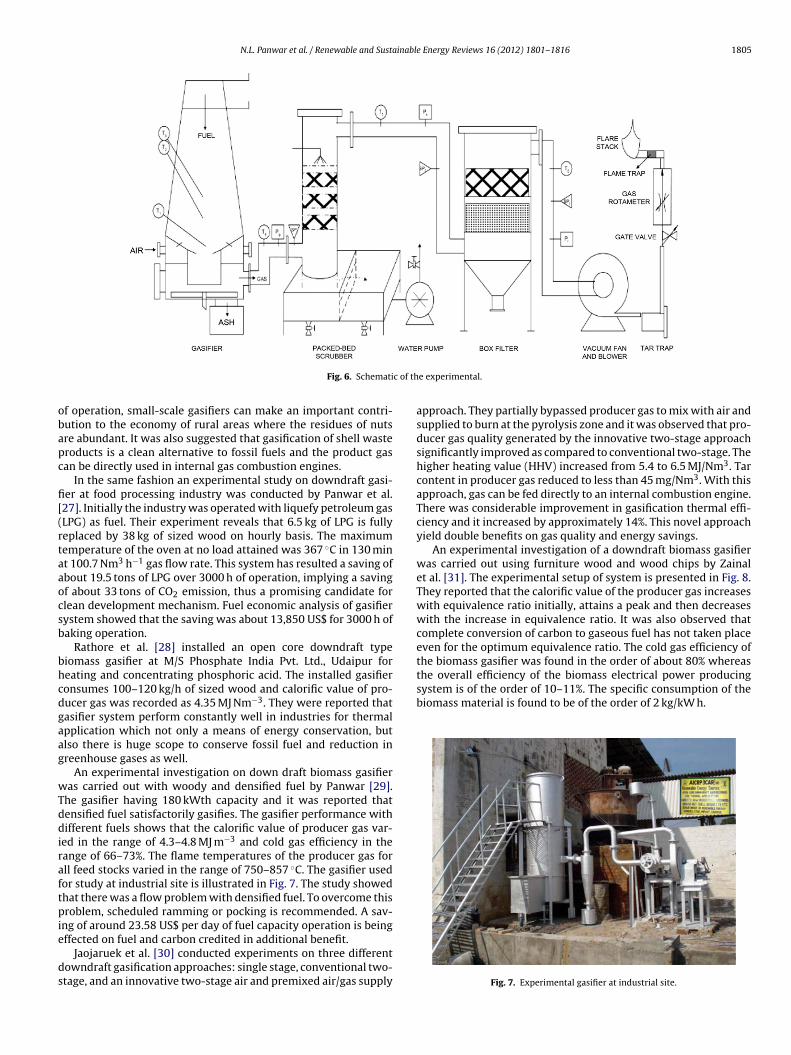
N.L. Panwar et al. / Renewable and Sustainable Energy Reviews 16 (2012) 1801– 1816 1805
c of th
obapc
fi[(rtaaocsb
bhcdgaag
wTddiraftpie
ds
the overall efficiency of the biomass electrical power producingsystem is of the order of 10–11%. The specific consumption of thebiomass material is found to be of the order of 2 kg/kW h.
Fig. 6. Schemati
f operation, small-scale gasifiers can make an important contri-ution to the economy of rural areas where the residues of nutsre abundant. It was also suggested that gasification of shell wasteroducts is a clean alternative to fossil fuels and the product gasan be directly used in internal gas combustion engines.
In the same fashion an experimental study on downdraft gasi-er at food processing industry was conducted by Panwar et al.27]. Initially the industry was operated with liquefy petroleum gasLPG) as fuel. Their experiment reveals that 6.5 kg of LPG is fullyeplaced by 38 kg of sized wood on hourly basis. The maximumemperature of the oven at no load attained was 367 ◦C in 130 mint 100.7 Nm3 h−1 gas flow rate. This system has resulted a saving ofbout 19.5 tons of LPG over 3000 h of operation, implying a savingf about 33 tons of CO2 emission, thus a promising candidate forlean development mechanism. Fuel economic analysis of gasifierystem showed that the saving was about 13,850 US$ for 3000 h ofaking operation.
Rathore et al. [28] installed an open core downdraft typeiomass gasifier at M/S Phosphate India Pvt. Ltd., Udaipur foreating and concentrating phosphoric acid. The installed gasifieronsumes 100–120 kg/h of sized wood and calorific value of pro-ucer gas was recorded as 4.35 MJ Nm−3. They were reported thatasifier system perform constantly well in industries for thermalpplication which not only a means of energy conservation, butlso there is huge scope to conserve fossil fuel and reduction inreenhouse gases as well.
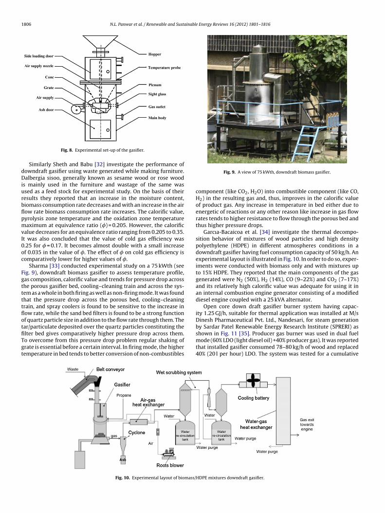
An experimental investigation on down draft biomass gasifieras carried out with woody and densified fuel by Panwar [29].
he gasifier having 180 kWth capacity and it was reported thatensified fuel satisfactorily gasifies. The gasifier performance withifferent fuels shows that the calorific value of producer gas var-
ed in the range of 4.3–4.8 MJ m−3 and cold gas efficiency in theange of 66–73%. The flame temperatures of the producer gas forll feed stocks varied in the range of 750–857 ◦C. The gasifier usedor study at industrial site is illustrated in Fig. 7. The study showedhat there was a flow problem with densified fuel. To overcome thisroblem, scheduled ramming or pocking is recommended. A sav-
ng of around 23.58 US$ per day of fuel capacity operation is being
ffected on fuel and carbon credited in additional benefit.Jaojaruek et al. [30] conducted experiments on three differentowndraft gasification approaches: single stage, conventional two-tage, and an innovative two-stage air and premixed air/gas supply
e experimental.
approach. They partially bypassed producer gas to mix with air andsupplied to burn at the pyrolysis zone and it was observed that pro-ducer gas quality generated by the innovative two-stage approachsignificantly improved as compared to conventional two-stage. Thehigher heating value (HHV) increased from 5.4 to 6.5 MJ/Nm3. Tarcontent in producer gas reduced to less than 45 mg/Nm3. With thisapproach, gas can be fed directly to an internal combustion engine.There was considerable improvement in gasification thermal effi-ciency and it increased by approximately 14%. This novel approachyield double benefits on gas quality and energy savings.
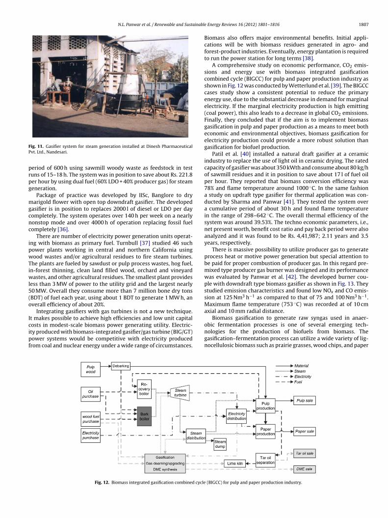
An experimental investigation of a downdraft biomass gasifierwas carried out using furniture wood and wood chips by Zainalet al. [31]. The experimental setup of system is presented in Fig. 8.They reported that the calorific value of the producer gas increaseswith equivalence ratio initially, attains a peak and then decreaseswith the increase in equivalence ratio. It was also observed thatcomplete conversion of carbon to gaseous fuel has not taken placeeven for the optimum equivalence ratio. The cold gas efficiency ofthe biomass gasifier was found in the order of about 80% whereas
Fig. 7. Experimental gasifier at industrial site.
1806 N.L. Panwar et al. / Renewable and Sustainable Energy Reviews 16 (2012) 1801– 1816
dDiurbflpmvI0oc
FgttttflotfiTgt
Fig. 8. Experimental set-up of the gasifier.
Similarly Sheth and Babu [32] investigate the performance ofowndraft gasifier using waste generated while making furniture.albergia sisoo, generally known as sesame wood or rose wood
s mainly used in the furniture and wastage of the same wassed as a feed stock for experimental study. On the basis of theiresults they reported that an increase in the moisture content,iomass consumption rate decreases and with an increase in the airow rate biomass consumption rate increases. The calorific value,yrolysis zone temperature and the oxidation zone temperatureaximum at equivalence ratio (�) = 0.205. However, the calorific
alue decreases for an equivalence ratio ranging from 0.205 to 0.35.t was also concluded that the value of cold gas efficiency was.25 for � = 0.17. It becomes almost double with a small increasef 0.035 in the value of �. The effect of � on cold gas efficiency isomparatively lower for higher values of �.
Sharma [33] conducted experimental study on a 75 kWth (seeig. 9), downdraft biomass gasifier to assess temperature profile,as composition, calorific value and trends for pressure drop acrosshe porous gasifier bed, cooling–cleaning train and across the sys-em as a whole in both firing as well as non-firing mode. It was foundhat the pressure drop across the porous bed, cooling–cleaningrain, and spray coolers is found to be sensitive to the increase inow rate, while the sand bed filters is found to be a strong functionf quartz particle size in addition to the flow rate through them. Thear/particulate deposited over the quartz particles constituting the
lter bed gives comparatively higher pressure drop across them.o overcome from this pressure drop problem regular shaking ofrate is essential before a certain interval. In firing mode, the higheremperature in bed tends to better conversion of non-combustiblesFig. 10. Experimental layout of biomass/
Fig. 9. A view of 75 kWth, downdraft biomass gasifier.
component (like CO2, H2O) into combustible component (like CO,H2) in the resulting gas and, thus, improves in the calorific valueof product gas. Any increase in temperature in bed either due toenergetic of reactions or any other reason like increase in gas flowrates tends to higher resistance to flow through the porous bed andthus higher pressure drops.
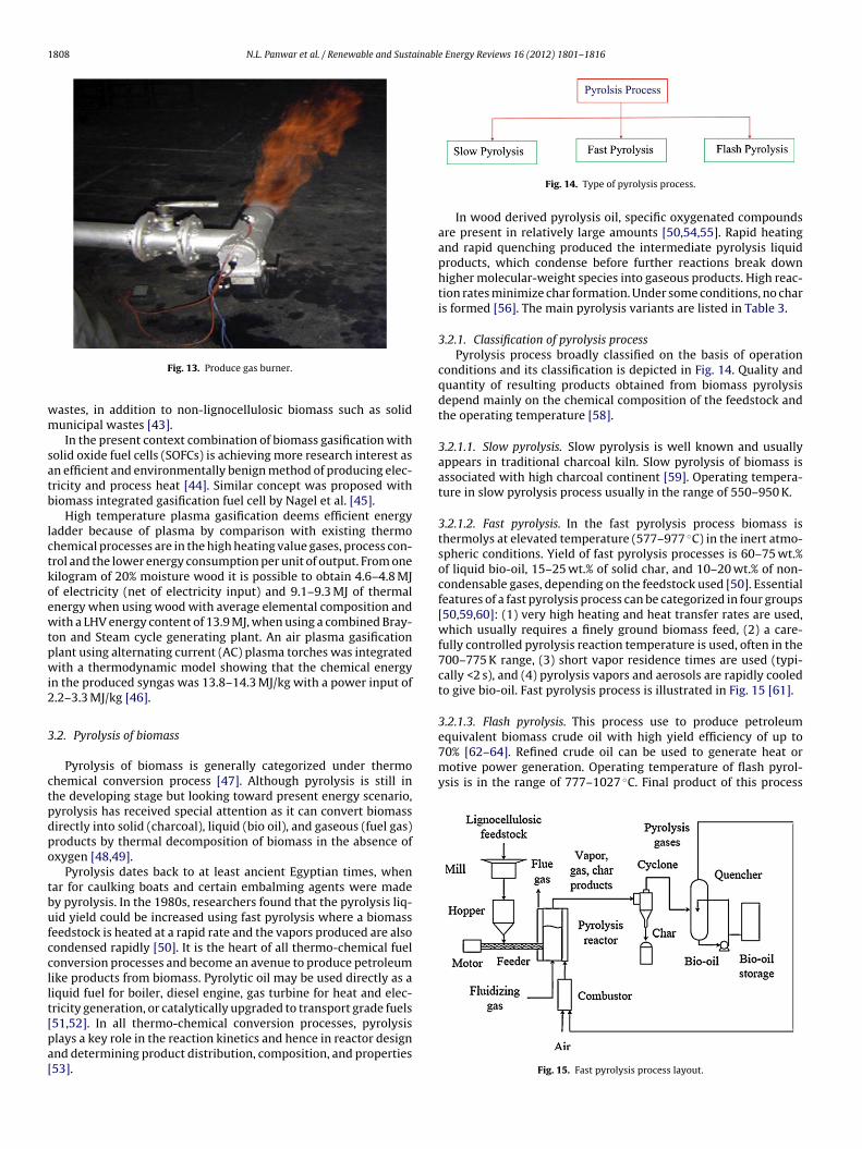
Garcıa-Bacaicoa et al. [34] investigate the thermal decompo-sition behavior of mixtures of wood particles and high densitypolyethylene (HDPE) in different atmospheres conditions in adowndraft gasifier having fuel consumption capacity of 50 kg/h. Anexperimental layout is illustrated in Fig. 10. In order to do so, exper-iments were conducted with biomass only and with mixtures upto 15% HDPE. They reported that the main components of the gasgenerated were N2 (50%), H2 (14%), CO (9–22%) and CO2 (7–17%)and its relatively high calorific value was adequate for using it inan internal combustion engine generator consisting of a modifieddiesel engine coupled with a 25 kVA alternator.
Open core down draft gasifier burner system having capac-ity 1.25 GJ/h, suitable for thermal application was installed at M/sDinesh Pharmaceutical Pvt. Ltd., Nandesari, for steam generationby Sardar Patel Renewable Energy Research Institute (SPRERI) asshown in Fig. 11 [35]. Producer gas burner was used in dual fuel
mode (60% LDO (light diesel oil) +40% producer gas). It was reportedthat installed gasifier consumed 78–80 kg/h of wood and replaced40% (20 l per hour) LDO. The system was tested for a cumulativeHDPE mixtures downdraft gasifier.
N.L. Panwar et al. / Renewable and Sustainabl
FP
prpg
mgcnc
ipwTiwl5(o
Icipf
ig. 11. Gasifier system for steam generation installed at Dinesh Pharmaceuticalvt. Ltd., Nandesari.
eriod of 600 h using sawmill woody waste as feedstock in testuns of 15–18 h. The system was in position to save about Rs. 221.8er hour by using dual fuel (60% LDO + 40% producer gas) for steameneration.
Package of practice was developed by IISc, Banglore to dryarigold flower with open top downdraft gasifier. The developed
asifier is in position to replaces 2000 l of diesel or LDO per dayompletely. The system operates over 140 h per week on a nearlyonstop mode and over 4000 h of operation replacing fossil fuelompletely [36].
There are number of electricity power generation units operat-ng with biomass as primary fuel. Turnbull [37] studied 46 suchower plants working in central and northern California usingood wastes and/or agricultural residues to fire steam turbines.
he plants are fueled by sawdust or pulp process wastes, hog fuel,n-forest thinning, clean land filled wood, orchard and vineyard
astes, and other agricultural residues. The smallest plant providesess than 3 MW of power to the utility grid and the largest nearly0 MW. Overall they consume more than 7 million bone dry tonsBDT) of fuel each year, using about 1 BDT to generate 1 MW h, anverall efficiency of about 20%.
Integrating gasifiers with gas turbines is not a new technique.t makes possible to achieve high efficiencies and low unit capital
osts in modest-scale biomass power generating utility. Electric-ty produced with biomass-integrated gasifier/gas turbine (BIG/GT)ower systems would be competitive with electricity producedrom coal and nuclear energy under a wide range of circumstances.Fig. 12. Biomass integrated gasification combined cycle
e Energy Reviews 16 (2012) 1801– 1816 1807
Biomass also offers major environmental benefits. Initial appli-cations will be with biomass residues generated in agro- andforest-product industries. Eventually, energy plantation is requiredto run the power station for long terms [38].
A comprehensive study on economic performance, CO2 emis-sions and energy use with biomass integrated gasificationcombined cycle (BIGCC) for pulp and paper production industry asshown in Fig. 12 was conducted by Wetterlund et al. [39]. The BIGCCcases study show a consistent potential to reduce the primaryenergy use, due to the substantial decrease in demand for marginalelectricity. If the marginal electricity production is high emitting(coal power), this also leads to a decrease in global CO2 emissions.Finally, they concluded that if the aim is to implement biomassgasification in pulp and paper production as a means to meet botheconomic and environmental objectives, biomass gasification forelectricity production could provide a more robust solution thangasification for biofuel production.
Patil et al. [40] installed a natural draft gasifier at a ceramicindustry to replace the use of light oil in ceramic drying. The ratedcapacity of gasifier was about 350 kWth and consume about 80 kg/hof sawmill residues and it in position to save about 17 l of fuel oilper hour. They reported that biomass conversion efficiency was78% and flame temperature around 1000 ◦C. In the same fashiona study on updraft type gasifier for thermal application was con-ducted by Sharma and Panwar [41]. They tested the system overa cumulative period of about 30 h and found flame temperaturein the range of 298–642 ◦C. The overall thermal efficiency of thesystem was around 39.53%. The techno economic parameters, i.e.,net present worth, benefit cost ratio and pay back period were alsoanalyzed and it was found to be Rs. 4,41,987; 2.11 years and 3.5years, respectively.
There is massive possibility to utilize producer gas to generateprocess heat or motive power generation but special attention tobe paid for proper combustion of producer gas. In this regard pre-mixed type producer gas burner was designed and its performancewas evaluated by Panwar et al. [42]. The developed burner cou-ple with downdraft type biomass gasifier as shown in Fig. 13. Theystudied emission characteristics and found low NOx and CO emis-sion at 125 Nm3 h−1 as compared to that of 75 and 100 Nm3 h−1.Maximum flame temperature (753 ◦C) was recorded at of 10 cmaxial and 10 mm radial distance.
Biomass gasification to generate raw syngas used in anaer-
obic fermentation processes is one of several emerging tech-nologies for the production of biofuels from biomass. Thegasification–fermentation process can utilize a wide variety of lig-nocellulosic biomass such as prairie grasses, wood chips, and paper(BIGCC) for pulp and paper production industry.
1808 N.L. Panwar et al. / Renewable and Sustainable Energy Reviews 16 (2012) 1801– 1816
wm
satb
lctkoewtpwi2
3
ctpdpo
tbufccllt[pa[
equivalent biomass crude oil with high yield efficiency of up to70% [62–64]. Refined crude oil can be used to generate heat ormotive power generation. Operating temperature of flash pyrol-ysis is in the range of 777–1027 ◦C. Final product of this process
Fig. 13. Produce gas burner.
astes, in addition to non-lignocellulosic biomass such as solidunicipal wastes [43].In the present context combination of biomass gasification with
olid oxide fuel cells (SOFCs) is achieving more research interest asn efficient and environmentally benign method of producing elec-ricity and process heat [44]. Similar concept was proposed withiomass integrated gasification fuel cell by Nagel et al. [45].
High temperature plasma gasification deems efficient energyadder because of plasma by comparison with existing thermohemical processes are in the high heating value gases, process con-rol and the lower energy consumption per unit of output. From oneilogram of 20% moisture wood it is possible to obtain 4.6–4.8 MJf electricity (net of electricity input) and 9.1–9.3 MJ of thermalnergy when using wood with average elemental composition andith a LHV energy content of 13.9 MJ, when using a combined Bray-
on and Steam cycle generating plant. An air plasma gasificationlant using alternating current (AC) plasma torches was integratedith a thermodynamic model showing that the chemical energy
n the produced syngas was 13.8–14.3 MJ/kg with a power input of.2–3.3 MJ/kg [46].
.2. Pyrolysis of biomass
Pyrolysis of biomass is generally categorized under thermohemical conversion process [47]. Although pyrolysis is still inhe developing stage but looking toward present energy scenario,yrolysis has received special attention as it can convert biomassirectly into solid (charcoal), liquid (bio oil), and gaseous (fuel gas)roducts by thermal decomposition of biomass in the absence ofxygen [48,49].
Pyrolysis dates back to at least ancient Egyptian times, whenar for caulking boats and certain embalming agents were madey pyrolysis. In the 1980s, researchers found that the pyrolysis liq-id yield could be increased using fast pyrolysis where a biomasseedstock is heated at a rapid rate and the vapors produced are alsoondensed rapidly [50]. It is the heart of all thermo-chemical fuelonversion processes and become an avenue to produce petroleumike products from biomass. Pyrolytic oil may be used directly as aiquid fuel for boiler, diesel engine, gas turbine for heat and elec-ricity generation, or catalytically upgraded to transport grade fuels51,52]. In all thermo-chemical conversion processes, pyrolysis
lays a key role in the reaction kinetics and hence in reactor designnd determining product distribution, composition, and properties53].Fig. 14. Type of pyrolysis process.
In wood derived pyrolysis oil, specific oxygenated compoundsare present in relatively large amounts [50,54,55]. Rapid heatingand rapid quenching produced the intermediate pyrolysis liquidproducts, which condense before further reactions break downhigher molecular-weight species into gaseous products. High reac-tion rates minimize char formation. Under some conditions, no charis formed [56]. The main pyrolysis variants are listed in Table 3.
3.2.1. Classification of pyrolysis processPyrolysis process broadly classified on the basis of operation
conditions and its classification is depicted in Fig. 14. Quality andquantity of resulting products obtained from biomass pyrolysisdepend mainly on the chemical composition of the feedstock andthe operating temperature [58].
3.2.1.1. Slow pyrolysis. Slow pyrolysis is well known and usuallyappears in traditional charcoal kiln. Slow pyrolysis of biomass isassociated with high charcoal continent [59]. Operating tempera-ture in slow pyrolysis process usually in the range of 550–950 K.
3.2.1.2. Fast pyrolysis. In the fast pyrolysis process biomass isthermolys at elevated temperature (577–977 ◦C) in the inert atmo-spheric conditions. Yield of fast pyrolysis processes is 60–75 wt.%of liquid bio-oil, 15–25 wt.% of solid char, and 10–20 wt.% of non-condensable gases, depending on the feedstock used [50]. Essentialfeatures of a fast pyrolysis process can be categorized in four groups[50,59,60]: (1) very high heating and heat transfer rates are used,which usually requires a finely ground biomass feed, (2) a care-fully controlled pyrolysis reaction temperature is used, often in the700–775 K range, (3) short vapor residence times are used (typi-cally <2 s), and (4) pyrolysis vapors and aerosols are rapidly cooledto give bio-oil. Fast pyrolysis process is illustrated in Fig. 15 [61].
3.2.1.3. Flash pyrolysis. This process use to produce petroleum
Fig. 15. Fast pyrolysis process layout.
N.L. Panwar et al. / Renewable and Sustainable Energy Reviews 16 (2012) 1801– 1816 1809
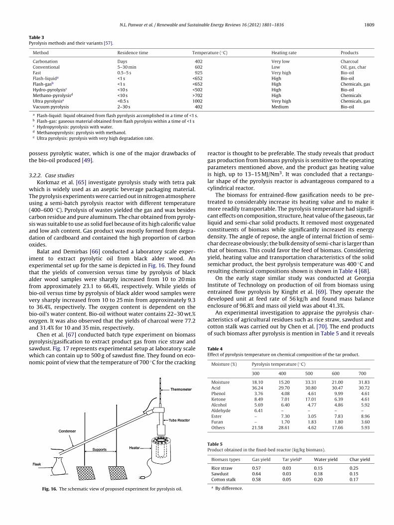
Table 3Pyrolysis methods and their variants [57].
Method Residence time Temperature (◦C) Heating rate Products
Carbonation Days 402 Very low CharcoalConventional 5–30 min 602 Low Oil, gas, charFast 0.5–5 s 925 Very high Bio-oilFlash-liquida <1 s <652 High Bio-oilFlash-gasb <1 s <652 High Chemicals, gasHydro-pyrolysisc <10 s <502 High Bio-oilMethano-pyrolysisd <10 s >702 High ChemicalsUltra pyrolysise <0.5 s 1002 Very high Chemicals, gasVacuum pyrolysis 2–30 s 402 Medium Bio-oil
a Flash-liquid: liquid obtained from flash pyrolysis accomplished in a time of <1 s.b Flash-gas: gaseous material obtained from flash pyrolysis within a time of <1 s
pt
3
wTu(csado
ietafbvtboa
pswn
An experimental investigation to appraise the pyrolysis char-acteristics of agricultural residues such as rice straw, sawdust andcotton stalk was carried out by Chen et al. [70]. The end productsof such biomass after pyrolysis is mention in Table 5 and it reveals
c Hydropyrolysis: pyrolysis with water.d Methanopyrolysis: pyrolysis with methanol.e Ultra pyrolysis: pyrolysis with very high degradation rate.
ossess pyrolytic water, which is one of the major drawbacks ofhe bio-oil produced [49].
.2.2. Case studiesKorkmaz et al. [65] investigate pyrolysis study with tetra pak
hich is widely used as an aseptic beverage packaging material.he pyrolysis experiments were carried out in nitrogen atmospheresing a semi-batch pyrolysis reactor with different temperature400–600 ◦C). Pyrolysis of wastes yielded the gas and wax besidesarbon residue and pure aluminum. The char obtained from pyroly-is was suitable to use as solid fuel because of its high calorific valuend low ash content. Gas product was mostly formed from degra-ation of cardboard and contained the high proportion of carbonxides.
Balat and Demirbas [66] conducted a laboratory scale exper-ment to extract pyrolytic oil from black alder wood. Anxperimental set up for the same is depicted in Fig. 16. They foundhat the yields of conversion versus time by pyrolysis of blacklder wood samples were sharply increased from 10 to 20 minrom approximately 23.1 to 66.4%, respectively. While yields ofio-oil versus time by pyrolysis of black alder wood samples wereery sharply increased from 10 to 25 min from approximately 9.3o 36.4%, respectively. The oxygen content is dependent on theio-oil’s water content. Bio-oil without water contains 22–30 wt.%xygen. It was also observed that the yields of charcoal were 77.2nd 31.4% for 10 and 35 min, respectively.
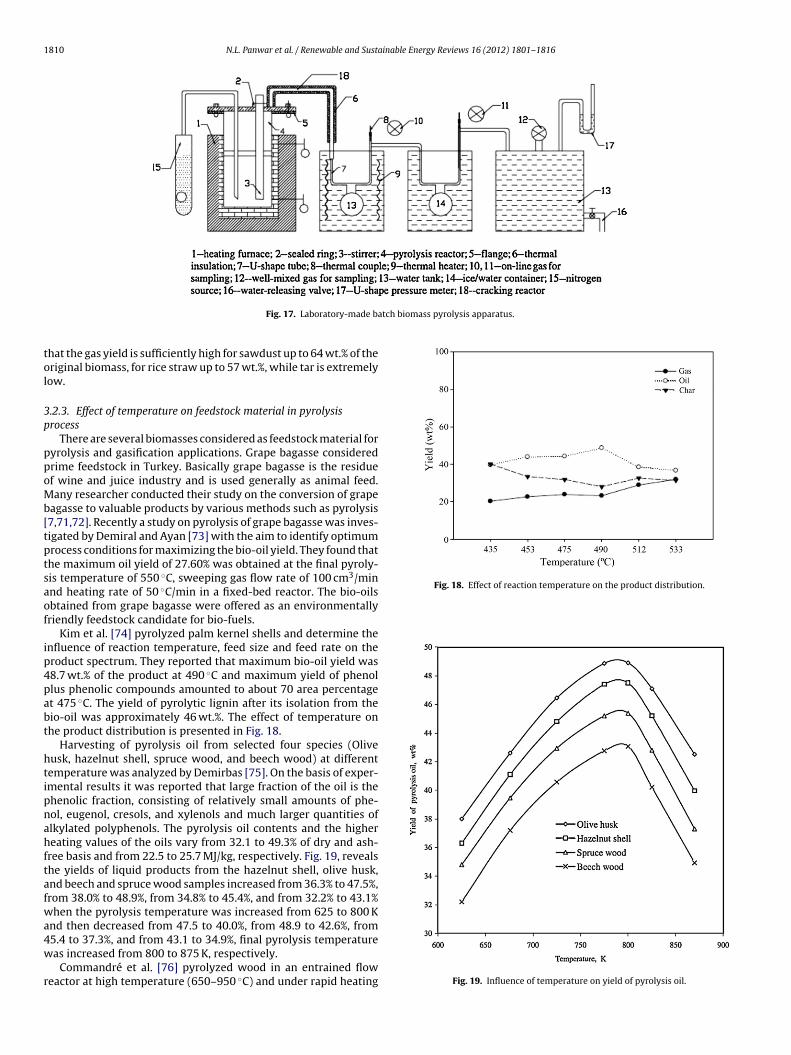
Chen et al. [67] conducted batch type experiment on biomass
yrolysis/gasification to extract product gas from rice straw andawdust. Fig. 17 represents experimental setup at laboratory scalehich can contain up to 500 g of sawdust fine. They found on eco-omic point of view that the temperature of 700 ◦C for the crackingFig. 16. The schematic view of proposed experiment for pyrolysis oil.
reactor is thought to be preferable. The study reveals that productgas production from biomass pyrolysis is sensitive to the operatingparameters mentioned above, and the product gas heating valueis high, up to 13–15 MJ/Nm3. It was concluded that a rectangu-lar shape of the pyrolysis reactor is advantageous compared to acylindrical reactor.
The biomass for entrained-flow gasification needs to be pre-treated to considerably increase its heating value and to make itmore readily transportable. The pyrolysis temperature had signifi-cant effects on composition, structure, heat value of the gaseous, tarliquid and semi-char solid products. It removed most oxygenatedconstituents of biomass while significantly increased its energydensity. The angle of repose, the angle of internal friction of semi-char decrease obviously; the bulk density of semi-char is larger thanthat of biomass. This could favor the feed of biomass. Consideringyield, heating value and transportation characteristics of the solidsemichar product, the best pyrolysis temperature was 400 ◦C andresulting chemical compositions shown is shown in Table 4 [68].
On the early stage similar study was conducted at GeorgiaInstitute of Technology on production of oil from biomass usingentrained flow pyrolysis by Kinght et al. [69]. They operate thedeveloped unit at feed rate of 56 kg/h and found mass balanceenclosure of 96.8% and mass oil yield was about 41.3%.
Table 4Effect of pyrolysis temperature on chemical composition of the tar product.
Moisture (%) Pyrolysis temperature (◦C)
300 400 500 600 700
Moisture 18.10 15.20 33.31 21.00 31.83Acid 36.24 29.70 30.80 30.47 30.72Phenol 3.76 4.08 4.61 9.99 4.61Ketone 8.49 7.01 17.01 6.39 4.61Alcohol 5.69 6.40 4.77 4.86 5.92Aldehyde 6.41 – – – –Ester – 7.30 3.05 7.83 8.96Furan – 1.70 1.83 1.80 3.60Others 21.58 28.61 4.62 17.66 5.93
Table 5Product obtained in the fixed-bed reactor (kg/kg biomass).
Biomass types Gas yield Tar yielda Water yield Char yield
Rice straw 0.57 0.03 0.15 0.25Sawdust 0.64 0.03 0.18 0.15Cotton stalk 0.58 0.05 0.20 0.17
a By difference.
1810 N.L. Panwar et al. / Renewable and Sustainable Energy Reviews 16 (2012) 1801– 1816
atch biomass pyrolysis apparatus.
tol
3p
ppoMb[tptsaof
ip4pabt
htipnahftafwa4w
r
Fig. 18. Effect of reaction temperature on the product distribution.
Fig. 17. Laboratory-made b
hat the gas yield is sufficiently high for sawdust up to 64 wt.% of theriginal biomass, for rice straw up to 57 wt.%, while tar is extremelyow.
.2.3. Effect of temperature on feedstock material in pyrolysisrocess
There are several biomasses considered as feedstock material foryrolysis and gasification applications. Grape bagasse consideredrime feedstock in Turkey. Basically grape bagasse is the residuef wine and juice industry and is used generally as animal feed.any researcher conducted their study on the conversion of grape
agasse to valuable products by various methods such as pyrolysis7,71,72]. Recently a study on pyrolysis of grape bagasse was inves-igated by Demiral and Ayan [73] with the aim to identify optimumrocess conditions for maximizing the bio-oil yield. They found thathe maximum oil yield of 27.60% was obtained at the final pyroly-is temperature of 550 ◦C, sweeping gas flow rate of 100 cm3/minnd heating rate of 50 ◦C/min in a fixed-bed reactor. The bio-oilsbtained from grape bagasse were offered as an environmentallyriendly feedstock candidate for bio-fuels.
Kim et al. [74] pyrolyzed palm kernel shells and determine thenfluence of reaction temperature, feed size and feed rate on theroduct spectrum. They reported that maximum bio-oil yield was8.7 wt.% of the product at 490 ◦C and maximum yield of phenollus phenolic compounds amounted to about 70 area percentaget 475 ◦C. The yield of pyrolytic lignin after its isolation from theio-oil was approximately 46 wt.%. The effect of temperature onhe product distribution is presented in Fig. 18.
Harvesting of pyrolysis oil from selected four species (Oliveusk, hazelnut shell, spruce wood, and beech wood) at differentemperature was analyzed by Demirbas [75]. On the basis of exper-mental results it was reported that large fraction of the oil is thehenolic fraction, consisting of relatively small amounts of phe-ol, eugenol, cresols, and xylenols and much larger quantities oflkylated polyphenols. The pyrolysis oil contents and the highereating values of the oils vary from 32.1 to 49.3% of dry and ash-
ree basis and from 22.5 to 25.7 MJ/kg, respectively. Fig. 19, revealshe yields of liquid products from the hazelnut shell, olive husk,nd beech and spruce wood samples increased from 36.3% to 47.5%,rom 38.0% to 48.9%, from 34.8% to 45.4%, and from 32.2% to 43.1%hen the pyrolysis temperature was increased from 625 to 800 K
nd then decreased from 47.5 to 40.0%, from 48.9 to 42.6%, from
5.4 to 37.3%, and from 43.1 to 34.9%, final pyrolysis temperatureas increased from 800 to 875 K, respectively.Commandré et al. [76] pyrolyzed wood in an entrained floweactor at high temperature (650–950 ◦C) and under rapid heating Fig. 19. Influence of temperature on yield of pyrolysis oil.
N.L. Panwar et al. / Renewable and Sustainable Energy Reviews 16 (2012) 1801– 1816 1811
S
cbpy(Cp
3
ahfrIctttTtc
qsbfu
s
TL
Fig. 20. Pathways from biomass-to-hydrogen.ource [79].
onditions (>103 K/s). During the experiments particle size keptetween 80–125 �m and 160–200 �m. It was elevated that tem-erature improve hydrogen yield in the gaseous product while COield decreases. Under nitrogen atmosphere, after 2 s at 950 ◦C, 76%daf) of the mass of wood is recovered as gases: CO, CO2, H2, CH4,2H2, C2H4 and H2O. An experiment performed under steam partialressure showed that hydrogen production is slightly enhanced.
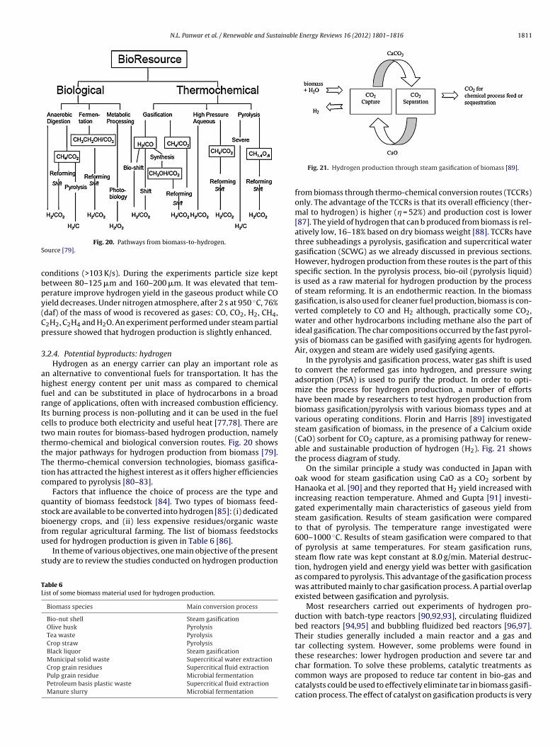
.2.4. Potential byproducts: hydrogenHydrogen as an energy carrier can play an important role as
n alternative to conventional fuels for transportation. It has theighest energy content per unit mass as compared to chemical
uel and can be substituted in place of hydrocarbons in a broadange of applications, often with increased combustion efficiency.ts burning process is non-polluting and it can be used in the fuelells to produce both electricity and useful heat [77,78]. There arewo main routes for biomass-based hydrogen production, namelyhermo-chemical and biological conversion routes. Fig. 20 showshe major pathways for hydrogen production from biomass [79].he thermo-chemical conversion technologies, biomass gasifica-ion has attracted the highest interest as it offers higher efficienciesompared to pyrolysis [80–83].
Factors that influence the choice of process are the type anduantity of biomass feedstock [84]. Two types of biomass feed-tock are available to be converted into hydrogen [85]: (i) dedicatedioenergy crops, and (ii) less expensive residues/organic waste
rom regular agricultural farming. The list of biomass feedstockssed for hydrogen production is given in Table 6 [86].In theme of various objectives, one main objective of the presenttudy are to review the studies conducted on hydrogen production
able 6ist of some biomass material used for hydrogen production.
Biomass species Main conversion process
Bio-nut shell Steam gasificationOlive husk PyrolysisTea waste PyrolysisCrop straw PyrolysisBlack liquor Steam gasificationMunicipal solid waste Supercritical water extractionCrop grain residues Supercritical fluid extractionPulp grain residue Microbial fermentationPetroleum basis plastic waste Supercritical fluid extractionManure slurry Microbial fermentation
Fig. 21. Hydrogen production through steam gasification of biomass [89].
from biomass through thermo-chemical conversion routes (TCCRs)only. The advantage of the TCCRs is that its overall efficiency (ther-mal to hydrogen) is higher (� = 52%) and production cost is lower[87]. The yield of hydrogen that can b produced from biomass is rel-atively low, 16–18% based on dry biomass weight [88]. TCCRs havethree subheadings a pyrolysis, gasification and supercritical watergasification (SCWG) as we already discussed in previous sections.However, hydrogen production from these routes is the part of thisspecific section. In the pyrolysis process, bio-oil (pyrolysis liquid)is used as a raw material for hydrogen production by the processof steam reforming. It is an endothermic reaction. In the biomassgasification, is also used for cleaner fuel production, biomass is con-verted completely to CO and H2 although, practically some CO2,water and other hydrocarbons including methane also the part ofideal gasification. The char compositions occurred by the fast pyrol-ysis of biomass can be gasified with gasifying agents for hydrogen.Air, oxygen and steam are widely used gasifying agents.
In the pyrolysis and gasification process, water gas shift is usedto convert the reformed gas into hydrogen, and pressure swingadsorption (PSA) is used to purify the product. In order to opti-mize the process for hydrogen production, a number of effortshave been made by researchers to test hydrogen production frombiomass gasification/pyrolysis with various biomass types and atvarious operating conditions. Florin and Harris [89] investigatedsteam gasification of biomass, in the presence of a Calcium oxide(CaO) sorbent for CO2 capture, as a promising pathway for renew-able and sustainable production of hydrogen (H2). Fig. 21 showsthe process diagram of study.
On the similar principle a study was conducted in Japan withoak wood for steam gasification using CaO as a CO2 sorbent byHanaoka et al. [90] and they reported that H2 yield increased withincreasing reaction temperature. Ahmed and Gupta [91] investi-gated experimentally main characteristics of gaseous yield fromsteam gasification. Results of steam gasification were comparedto that of pyrolysis. The temperature range investigated were600–1000 ◦C. Results of steam gasification were compared to thatof pyrolysis at same temperatures. For steam gasification runs,steam flow rate was kept constant at 8.0 g/min. Material destruc-tion, hydrogen yield and energy yield was better with gasificationas compared to pyrolysis. This advantage of the gasification processwas attributed mainly to char gasification process. A partial overlapexisted between gasification and pyrolysis.
Most researchers carried out experiments of hydrogen pro-duction with batch-type reactors [90,92,93], circulating fluidizedbed reactors [94,95] and bubbling fluidized bed reactors [96,97].Their studies generally included a main reactor and a gas andtar collecting system. However, some problems were found inthese researches: lower hydrogen production and severe tar and
char formation. To solve these problems, catalytic treatments ascommon ways are proposed to reduce tar content in bio-gas andcatalysts could be used to effectively eliminate tar in biomass gasifi-cation process. The effect of catalyst on gasification products is very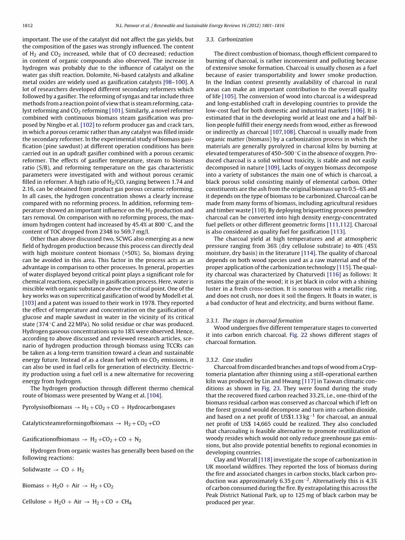
1 ainabl
itoihwmlfmlcpitficrrpfi2Icptic
fiwcaocmk[tgsHanbecie
r
P
C
G
f
S
B
C
812 N.L. Panwar et al. / Renewable and Sust
mportant. The use of the catalyst did not affect the gas yields, buthe composition of the gases was strongly influenced. The contentf H2 and CO2 increased, while that of CO decreased; reductionn content of organic compounds also observed. The increase inydrogen was probably due to the influence of catalyst on theater gas shift reaction. Dolomite, Ni-based catalysts and alkalineetal oxides are widely used as gasification catalysts [98–100]. A
ot of researchers developed different secondary reformers whichollowed by a gasifier. The reforming of syngas and tar include three
ethods from a reaction point of view that is steam reforming, cata-yst reforming and CO2 reforming [101]. Similarly, a novel reformerombined with continuous biomass steam gasification was pro-osed by Ningbo et al. [102] to reform producer gas and crack tars,
n which a porous ceramic rather than any catalyst was filled insidehe secondary reformer. In the experimental study of biomass gasi-cation (pine sawdust) at different operation conditions has beenarried out in an updraft gasifier combined with a porous ceramiceformer. The effects of gasifier temperature, steam to biomassatio (S/B), and reforming temperature on the gas characteristicarameters were investigated with and without porous ceramiclled in reformer. A high ratio of H2/CO, ranging between 1.74 and.16, can be obtained from product gas porous ceramic reforming.
n all cases, the hydrogen concentration shows a clearly increaseompared with no reforming process. In addition, reforming tem-erature showed an important influence on the H2 production andars removal. On comparison with no reforming process, the max-mum hydrogen content had increased by 45.4% at 800 ◦C, and theontent of TOC dropped from 2348 to 569.7 mg/l.
Other than above discussed two, SCWG also emerging as a neweld of hydrogen production because this process can directly dealith high moisture content biomass (>50%). So, biomass drying
an be avoided in this area. This factor in the process acts as andvantage in comparison to other processes. In general, propertiesf water displayed beyond critical point plays a significant role forhemical reactions, especially in gasification process. Here, water isiscible with organic substance above the critical point. One of the
ey works was on supercritical gasification of wood by Modell et al.103] and a patent was issued to their work in 1978. They reportedhe effect of temperature and concentration on the gasification oflucose and maple sawdust in water in the vicinity of its criticaltate (374 ◦C and 22 MPa). No solid residue or char was produced.ydrogen gaseous concentrations up to 18% were observed. Hence,ccording to above discussed and reviewed research articles, sce-ario of hydrogen production through biomass using TCCRs cane taken as a long-term transition toward a clean and sustainablenergy future. Instead of as a clean fuel with no CO2 emissions, itan also be used in fuel cells for generation of electricity. Electric-ty production using a fuel cell is a new alternative for recoveringnergy from hydrogen.
The hydrogen production through different thermo chemicaloute of biomass were presented by Wang et al. [104].
yrolysisofbiomass → H2 + CO2 + CO + Hydrocarbongases
atalyticsteamreformingofbiomass → H2 + CO2 +CO
asificationofbiomass → H2 +CO2 + CO + N2
Hydrogen from organic wastes has generally been based on theollowing reactions:
olidwaste → CO + H2
iomass + H2O + Air → H2 + CO2
ellulose + H2O + Air → H2 + CO + CH4
e Energy Reviews 16 (2012) 1801– 1816
3.3. Carbonization
The direct combustion of biomass, though efficient compared toburning of charcoal, is rather inconvenient and polluting becauseof extensive smoke formation. Charcoal is usually chosen as a fuelbecause of easier transportability and lower smoke production.In the Indian context presently availability of charcoal in ruralareas can make an important contribution to the overall qualityof life [105]. The conversion of wood into charcoal is a widespreadand long-established craft in developing countries to provide thelow-cost fuel for both domestic and industrial markets [106]. It isestimated that in the developing world at least one and a half bil-lion people fulfill their energy needs from wood, either as firewoodor indirectly as charcoal [107,108]. Charcoal is usually made fromorganic matter (biomass) by a carbonization process in which thematerials are generally pyrolyzed in charcoal kilns by burning atelevated temperatures of 450–500 ◦C in the absence of oxygen. Pro-duced charcoal is a solid without toxicity, is stable and not easilydecomposed in nature [109]. Lacks of oxygen biomass decomposeinto a variety of substances the main one of which is charcoal, ablack porous solid consisting mainly of elemental carbon. Otherconstituents are the ash from the original biomass up to 0.5–6% andit depends on the type of biomass to be carbonized. Charcoal can bemade from many forms of biomass, including agricultural residuesand timber waste [110]. By deploying briquetting process powderycharcoal can be converted into high density energy-concentratedfuel pellets or other different geometric forms [111,112]. Charcoalis also considered as quality fuel for gasification [113].
The charcoal yield at high temperatures and at atmosphericpressure ranging from 36% (dry cellulose substrate) to 40% (45%moisture, dry basis) in the literature [114]. The quality of charcoaldepends on both wood species used as a raw material and of theproper application of the carbonization technology [115]. The qual-ity charcoal was characterized by Chaturvedi [116] as follows: Itretains the grain of the wood; it is jet black in color with a shiningluster in a fresh cross-section. It is sonorous with a metallic ring,and does not crush, nor does it soil the fingers. It floats in water, isa bad conductor of heat and electricity, and burns without flame.
3.3.1. The stages in charcoal formationWood undergoes five different temperature stages to converted
it into carbon enrich charcoal. Fig. 22 shows different stages ofcharcoal formation.
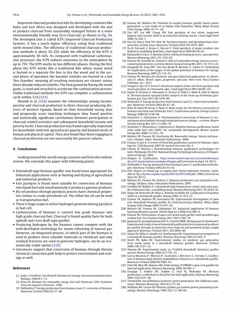
3.3.2. Case studiesCharcoal from discarded branches and tops of wood from a Cryp-
tomeria plantation after thinning using a still-operational earthenkiln was produced by Lin and Hwang [117] in Taiwan climatic con-ditions as shown in Fig. 23. They were found during the studythat the recovered fixed carbon reached 33.2%, i.e., one-third of thebiomass residual carbon was conserved as charcoal which if left onthe forest ground would decompose and turn into carbon dioxide,and based on a net profit of US$1.13 kg−1 for charcoal, an annualnet profit of US$ 14,665 could be realized. They also concludedthat charcoaling is feasible alternative to promote reutilization ofwoody resides which would not only reduce greenhouse gas emis-sions, but also provide potential benefits to regional economies indeveloping countries.
Clay and Worrall [118] investigate the scope of carbonization inUK moorland wildfires. They reported the loss of biomass during
the fire and associated changes in carbon stocks, black carbon pro-duction was approximately 6.35 g cm−2. Alternatively this is 4.3%of carbon consumed during the fire. By extrapolating this across thePeak District National Park, up to 125 mg of black carbon may beproduced per year.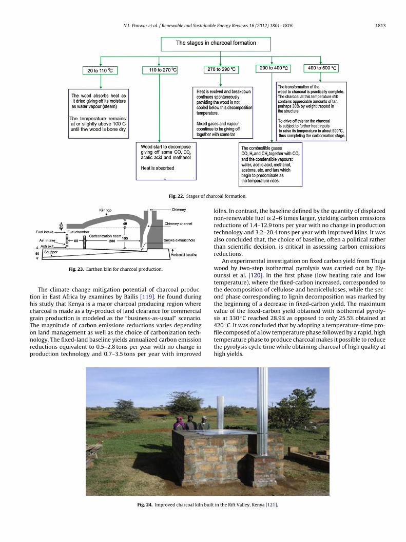
N.L. Panwar et al. / Renewable and Sustainable Energy Reviews 16 (2012) 1801– 1816 1813
Fig. 22. Stages of char
thcgTonrp
file composed of a low temperature phase followed by a rapid, high
Fig. 23. Earthen kiln for charcoal production.
The climate change mitigation potential of charcoal produc-ion in East Africa by examines by Bailis [119]. He found duringis study that Kenya is a major charcoal producing region whereharcoal is made as a by-product of land clearance for commercialrain production is modeled as the “business-as-usual” scenario.he magnitude of carbon emissions reductions varies dependingn land management as well as the choice of carbonization tech-
ology. The fixed-land baseline yields annualized carbon emissioneductions equivalent to 0.5–2.8 tons per year with no change inroduction technology and 0.7–3.5 tons per year with improvedFig. 24. Improved charcoal kiln built
coal formation.
kilns. In contrast, the baseline defined by the quantity of displacednon-renewable fuel is 2–6 times larger, yielding carbon emissionsreductions of 1.4–12.9 tons per year with no change in productiontechnology and 3.2–20.4 tons per year with improved kilns. It wasalso concluded that, the choice of baseline, often a political ratherthan scientific decision, is critical in assessing carbon emissionsreductions.
An experimental investigation on fixed carbon yield from Thujawood by two-step isothermal pyrolysis was carried out by Ely-ounssi et al. [120]. In the first phase (low heating rate and lowtemperature), where the fixed-carbon increased, corresponded tothe decomposition of cellulose and hemicelluloses, while the sec-ond phase corresponding to lignin decomposition was marked bythe beginning of a decrease in fixed-carbon yield. The maximumvalue of the fixed-carbon yield obtained with isothermal pyroly-sis at 330 ◦C reached 28.9% as opposed to only 25.5% obtained at420 ◦C. It was concluded that by adopting a temperature-time pro-
temperature phase to produce charcoal makes it possible to reducethe pyrolysis cycle time while obtaining charcoal of high quality athigh yields.
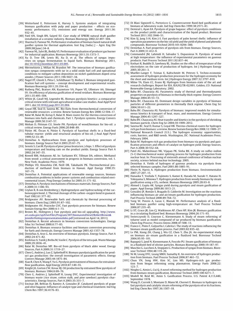
in the Rift Valley, Kenya [121].
1 ainabl
IteTSetatupio‘tgUc
ptaacpfhc
4
r
•
•
•
•
•
•
•
R
814 N.L. Panwar et al. / Renewable and Sust
Improved charcoal production kiln for developing countries likendia and East Africa was designed and developed with the aimo produce charcoal from sustainably managed forests in a morenvironmentally friendly way (Eco-Charcoal) as shown in Fig. 24.he developed unit is called ICPS (Improved Charcoal Productionystem). It has a much higher efficiency rating than traditionalarth-mound kilns. The efficiency of traditional charcoal produc-ion methods is about 10–22% while the efficiency of the ICPS ispproximately 30–42%. As compared with traditional carboniza-ion processes, the ICPS reduces emissions to the atmosphere byp to 75%. The ICPS works in two different phases. During the firsthase the ICPS works like a traditional kiln where waste wood
s burned in a separate fire box to dry the wood and in the sec-nd phase of operation the harmful volatiles are burned in a hot
fire chamber’ meaning all resulting emissions are cleaner, minushese already reduced volatiles. The heat gained by flaring the woodazes, is used and recycled to accelerate the carbonization process.nlike traditional methods the ICPS can complete a carbonizationycle within 12 h [121].
Khundi et al. [122] examine the relationships among income,overty and charcoal production in three charcoal-producing dis-ricts of western Uganda. Based on their household survey datand propensity score matching techniques they found positivend statistically significant correlations between participation inharcoal-related activities and subsequent household income andoverty levels. Charcoal production was found especially importantor households with low agricultural capacity and limited stocks ofuman and physical capital. They also found that those engaging inharcoal production are not necessarily the poorest cohorts.
. Conclusions
Looking toward the world energy scenario and from this holisticeview. We conclude this paper with following points:
Downdraft type biomass gasifier was found most appropriate forindustrial applications such as heating and drying of agriculturaland industrial products.Fast pyrolysis is found most suitable for conversion of biomassinto liquid fuel and simultaneously it produces gaseous products.Bio oil produce through pyrolysis process have chemical proper-ties similar to crude petroleum oil. The refine bio oil can be usedas transportation fuel.There is huge scope to utilize hydrogen generate during pyrolysisin fuel cell.Carbonization of biomass is convert low grade biomass intohigh grade charcoal fuel. Charcoal is found quality fuels for bothupdraft and cross draft type gasifier.Producing hydrogen by the biomass cannot compete with thewell-developed technology for steam-reforming of natural gas.However, an integrated process, in which part of the biomass isused to produce more valuable materials or chemicals and onlyresidual fractions are used to generate hydrogen, can be an eco-nomically viable option [123].Literatures support that conversion of biomass through thermochemical conversion path help to protect environment and ecol-ogy as well.
eferences
[1] Judy L, Trimble JL, Van Hook RI. Biomass for energy: the environmental issues.
Biomass 1984;6:3–13.[2] Klass DL. Biomass for renewable energy, fuel and chemicals. USA: AcademicPress An imprint of Elsevier; 1998.
[3] McKendry P. Energy production from biomass (part 1): overview of biomass.Bioresour Technol 2002;83:37–46.
e Energy Reviews 16 (2012) 1801– 1816
[4] Panwar NL, Rathore NS. Potential of surplus biomass gasifier based powergeneration: a case study of an Indian state Rajasthan. Mitig Adapt StrategGlob Change 2009;14:711–20.
[5] Tsai WT, Lee MK, Chang YM. Fast pyrolysis of rice straw, sugarcanebagasse and coconut shell in an induction-heating reactor. J Anal Appl Pyrol2006;76:230–7.
[6] Kim SS, Kim J, Park YH, Park YK. Pyrolysis kinetics and decomposition char-acteristics of pine trees. Bioresour Technol 2010;101:9797–802.
[7] Xu R, Ferrante L, Briens C, Berruti F. Flash pyrolysis of grape residues intobiofuel in a bubbling fluid bed. J Anal Appl Pyrol 2009;86:58–65.
[8] Kobayashi N, Fan L-S. Biomass direct chemical looping process: a perspective.Biomass Bioenergy 2011;35:1252–62.
[9] Panwar NL, Kaushik SC, Kothari S. Role of renewable energy sources in envi-ronmental protection: a review. Renew Sustain Energy Rev 2011;15:1513–24.
[10] Hoogwijk M, Faaij APC, Van den Broek R, Berndes G, Gielen D, TurkenburgW. Exploration of the ranges of the global potential of biomass for energy.Biomass Bioenergy 2003;25:119–33.
[11] Panwar NL. Biomass for domestic and agro industrial applications. In: Botan-nini LF, editor. Wood: types, properties, and uses. New York: Nova SciencePublisher, Inc.; 2011.
[12] Nurgül O, Ays eE P, Ersan P. Structural analysis of bio-oils from pyrolysis andsteam pyrolysis of cottonseed cake. J Anal Appl Pyrol 2001;60:89–101.
[13] Hanne R, Kristina K, Alexander K, Arunas B, Pekka S, Matti R, Outi K, MaritaN. Thermal plasma-sprayed nickel catalysts in the clean-up of biomass gasi-fication gas. Fuel 2011;90:1076–89.
[14] McKendry P. Energy production from biomass (part 2): conversion technolo-gies. Bioresour Technol 2002;83:47–54.
[15] Balat M, Balat M, Kırtay E, Balat H. Main routes for the thermo-conversion ofbiomass into fuels and chemicals. Part 2. Gasification systems. Energy ConversManage 2009;50:3158–68.
[16] Damartzis T, Zabaniotou A. Thermochemical conversion of biomass to sec-ond generation biofuels through integrated process design – a review. RenewSustain Energy Rev 2011;15:366–78.
[17] Seitarides T, Athanasiou C, Zabaniotou A. Modular biomass gasification-basedsolid oxide fuel cells (SOFC) for sustainable development. Renew SustainEnergy Rev 2008;12:1251–76.
[18] Rathore NS, Panwar NL, Kurchania AK. Renewable energy: theory and prac-tices. Udaipur, India: Himanshu Publications; 2008.
[19] Chopra A, Jain A. A review of fixed bed gasification system for biomass. AgricEng Int: CIGR Ejournal 2007;IX. Invited Overview No. 5.
[20] Ciferno JP, Marano J. Benchmarking biomass gasification technologies forfuels. Pittsburgh, PA, USA: National Energy Technology Laboratory, US Depart-ment of Energy; 2002.
[21] Klepper R. Gasification. http://www.emnrd.state.nm.us/emnrd/biomass/docs/GF presentations/combppt-Klepper.pdf [retrieved on April 14, 2011].
[22] McKendry P. Energy production from biomass (part 3): gasification technolo-gies. Bioresour Technol 2002;83:55–63.
[23] FAO. Report on Wood gas as engine fuel. Forest Industries Division. Avail-able at: ftp://ftp.fao.org/docrep/fao/t0512e/t0512e00.pdf; 1986 [retrieved onApril 20, 2011].
[24] Rathore NS, Panwar NL, Kothari S. Biomass production and utilization tech-nology. Udaipur, India: Himanshu Publications; 2007.
[25] Gordillo ED, Belghit A. A downdraft high temperature steam-only solar gasi-fier of biomass char: a modelling study. Biomass Bioenergy 2011;35:2034–43.
[26] Dogru M, Howarth CR, Akay G, Kskinler B, Malik AA. Gasification of hazelnutshells in a downdraft gasifier. Energy 2002;27:415–27.
[27] Panwar NL, Rathore NS, Kurchania AK. Experimental investigation of opencore downdraft biomass gasifier for food processing industry. Mitig AdaptStrateg Glob Change 2009;14:547–56.
[28] Rathore NS, Panwar NL, Chiplunkar VY. Industrial application of biomassbased gasification system. World Appl Sci J 2008;5(4):406–9.
[29] Panwar NL. Performance of open core down draft gasifier with densified agroresidue fuel. Int J Sustain Energy 2011;30(5):302–10.
[30] Jaojaruek K, Jarungthammachote S, Gratuito MKB, Wongsuwan H, Homhual S.Experimental study of wood downdraft gasification for an improved producergas quality through an innovative two-stage air and premixed air/gas supplyapproach. Bioresour Technol 2011;102:4834–40.
[31] Zainal ZA, Rifau A, Quadir GA, Seetharamu KN. Experimental investigation ofa downdraft biomass gasifier. Biomass Bioenergy 2002;23:283–9.
[32] Sheth PN, Babu BV. Experimental studies on producer gas generationfrom wood waste in a downdraft biomass gasifier. Bioresour Technol2009;100:3127–33.
[33] Sharma AK. Experimental study on 75 kWth downdraft (biomass) gasifiersystem. Renew Energy 2009;34:1726–33.
[34] Garcıa-Bacaicoa P, Mastral JF, Ceamanos J, Berrueco C, Serrano S. Gasifica-tion of biomass/high density polyethylene mixtures in a downdraft gasifier.Bioresour Technol 2008;99:5485–91.
[35] Patel SR, Bhoi PR, Sharma AM. Field-testing of SPRERI’s open core gasifier forthermal application. Biomass Bioenergy 2006;30:580–3.
[36] Dasappa S, Sridhar HV, Sridhar G, Paul PJ, Mukunda HS. Biomassgasification-a substitute to fossil fuel for heat application. Biomass Bioenergy
2003;25(6):637–49.[37] Turnbull JH. Use of biomass in electric power generation: the California expe-rience. Biomass Bioenergy 1993;4(2):75–84.
[38] Williams RH, Larson ED. Biomass gasifier gas turbine power generating tech-nology. Biomass Bioenergy 1996;10(2-3):149–66.
inabl
[103] Modell M, Reid RC, Amin S. Gasification Process. U.S. Patent 4,113,446;
N.L. Panwar et al. / Renewable and Susta
[39] Wetterlund E, Pettersson K, Harvey S. Systems analysis of integratingbiomass gasification with pulp and paper production – effects on eco-nomic performance, CO2 emissions and energy use. Energy 2011;36:932–41.
[40] Patil KN, Singh RN, Saiyed SU. Case study of SPRERI natural draft gasifierinstallation at a ceramic industry. Biomass Bioenergy 2002;22:497–504.
[41] Sharma D, Panwar NL. Performance evaluation of biomass based natural draftgasifier system for thermal application. Inst Eng (India) J – Agric Eng Div2009;90(June):34–8.
[42] Panwar NL, Salvi BL, Reddy VS. Performance evaluation of producer gas burnerfor industrial application. Biomass Bioenergy 2011;35:1373–7.
[43] Xu D, Tree DR, Lewis RS, Xu D, et al. The effects of syngas impu-rities on syngas fermentation to liquid fuels. Biomass Bioenergy 2011,doi:10.1016/j.biombioe.2011.03.005.
[44] Mermelstein J, Millan M, Brandon NP. The interaction of biomass gasifica-tion syngas components with tar in a solid oxide fuel cell and operationalconditions to mitigate carbon deposition on nickel–gadolinium doped ceriaanodes. J Power Sources 2011;196:5027–34.
[45] Nagel FP, Ghosh S, Pitta C, Schildhauer TJ, Biollaz S. Biomass integrated gasi-fication fuel cell systems – concept development and experimental results.Biomass Bioenergy 2011;35:354–62.
[46] Rutberg PhG, Bratsev AN, Kuznetsov VA, Popov VE, Ufimtsev AA, ShtengelSV. On efficiency of plasma gasification of wood residues. Biomass Bioenergy2011;35:495–504.
[47] White JE, Catall WJ, Legendre BL. Biomass pyrolysis kinetics: a comparativecritical review with relevant agricultural residue case studies. Anal Appl Pyrol2011, doi:10.1016/j.jaap.2011.01.004.
[48] Goyal HB, Seal D, Saxena RC. Bio-fuels from thermochemical conversion ofrenewable resources: a review. Renew Sustain Energy Rev 2008;12:504–17.
[49] Balat M, Balat M, Kırtay E, Balat H. Main routes for the thermo-conversion ofbiomass into fuels and chemicals. Part 1. Pyrolysis systems. Energy ConversManage 2009;50:3147–57.
[50] Mohan D, Pittman CU, Steele PH. Pyrolysis of wood/biomass for bio-oil: acritical review. Energy Fuels 2006;20:848–89.
[51] Pütün AE, Özcan A, Pütün E. Pyrolysis of hazelnut shells in a fixed-bedtubular reactor: yields and structural analysis of bio-oil. J Anal Appl Pyrol1999;52:33–49.
[52] Demirbas A. Hydrocarbons from pyrolysis and hydrolysis processes ofbiomass. Energy Source Part A 2003;25:67–75.
[53] Sensöz S, Can M. Pyrolysis of pine (pinus brutia ten.) chips. 1. Effect of pyrolysistemperature and heating rate on the product yields. Energy Source Part A2002;24:347–55.
[54] Rowell RM, Hokanson AE. In: Sarkanen KV, Tillman DA, editors. Methanolfrom wood: a critical assessment in progress in biomass conversion, vol. 1.New York: Academic Press; 1979.
[55] Phillips VD, Kinoshita CM, Neill DR, Takahashi PK. Thermochemical pro-duction of methanol from biomass in Hawaii. Appl Energy 1990;35:167–75.
[56] Demirbas A. Potential applications of renewable energy sources, biomasscombustion problems in boiler power systems and combustion related envi-ronmental issues. Prog Energy Combus Sci 2005;31:171–92.
[57] Demirbas A. Pyrolysis mechanisms of biomass materials. Energy Sources, PartA 2009;31:1186–93.
[58] Ceylan R, B-son Bredenberg J. Hydrogenolysis and hydrocracking of the car-bonoxygen bond. 2. Thermal cleavage of the carbon–oxygen bond in guaiacol.Fuel 1982;61:377–82.
[59] Bridgwater AV. Renewable fuels and chemicals by thermal processing ofbiomass. Chem Eng J 2003;91:87–102.
[60] Bridgwater AV, Peacocke GVC. Fast pyrolysis processes for biomass. RenewSustain Energy Rev 2000;4:1–73.
[61] Brown RC, Holmgren J. Fast pyrolysis and bio-oil upgrading. http://www.ars.usda.gov/sp2UserFiles/Program/307/biomasstoDiesel/RobertBrown&JenniferHolmgrenpresentationslides.pdf [retrieved on April 14, 2011].
[62] Demirbas A. Recent advances in biomass conversion technologies. EnergyEduc Sci Technol 2000;6:77–83.
[63] Demirbas A. Biomass resource facilities and biomass conversion processingfor fuels and chemicals. Energy Convers Manage 2001;42:1357–78.
[64] Demirbas A, Arın G. An overview of biomass pyrolysis. Energy Source, Part A2002;24:471–82.
[65] Korkmaz A, Yanik J, Brebu M, Vasile C. Pyrolysis of the tetra pak. Waste Manage2009;29:2836–41.
[66] Balat M, Demirbas MF. Bio-oil from pyrolysis of black alder wood. EnergySources, Part A 2009;31:1719–27.
[67] Chen G, Andries J, Luo Z, Spliethoff H. Biomass pyrolysis/gasification for prod-uct gas production: the overall investigation of parametric effects. EnergyConvers Manage 2003;44:1875–84.
[68] Xiao R, Chen X, Wang F, Yu G. Pyrolysis pretreatment of biomass for entrained-flow gasification. Appl Energy 2010;87:149–55.
[69] Knight JA, Gorton CW, Kovac RJ. Oil production by entrained flow pyrolysis ofbiomass. Biomass 1984;6:69–76.
[70] Chen G, Andries J, Spliethoff H, Leung DYC. Experimental investigation ofbiomass waste (rice straw, cotton stalk, and pine sawdust) pyrolysis char-
acteristics. Energy Sources, Part A 2003;35:331–7.[71] Encinar JM, Beltran FJ, Ramiro A, Gonzalez JF. Catalyzed pyrolysis of grapeand olive bagasse. Influence of catalyst type and chemical treatment. Ind EngChem Res 1997;36:4176–83.
e Energy Reviews 16 (2012) 1801– 1816 1815
[72] Di Blasi Signorell G, Portoricco G. Countercurrent fixed-bed gasification ofbiomass at laboratory scale. Ind Eng Chem Res 1999;38:2571–81.
[73] Demiral L, Ayan EA. Pyrolysis of grape bagasse: effect of pyrolysis conditionson the product yields and characterization of the liquid product. BioresourTechnol 2011;102:3946–51.
[74] Kim SJ, Jung S-H, Kim J-S. Fast pyrolysis of palm kernel shells: influence ofoperation parameters on the bio-oil yield and the yield of phenol and phenoliccompounds. Bioresour Technol 2010;101:9294–300.
[75] Demirbas A. Fuel properties of pyrolysis oils from biomass. Energy Sources,Part A 2009;31:412–9.
[76] Commandré JM, Lahmidi H, Salvador S, Dupassieux N. Pyrolysis of woodat high temperature: the influence of experimental parameters on gaseousproducts. Fuel Process Technol 2011;92:837–44.
[77] Kothari R, Buddhi D, Sawhney RL. Studies on the effect of temperature of theelectrolytes on the rate of production of hydrogen. Int J Hydrogen Energy2005;30:261–3.
[78] Mueller-Langer F, Tzimas E, Kaltschmitt M, Peteves S. Techno-economicassessment of hydrogen production processes for the hydrogen economy forthe short and medium term. Int J Hydrogen Energy 2007;32:3797–810.
[79] Milne TA, Elam CC, Evans RJ. Hydrogen from biomass-state of the art andresearch challenges. Report for IEA, IEA/H2/TR-02/001. Golden, CO: NationalRenewable Energy Laboratory; 2002.
[80] Babu BV, Chaurasia AS. Parametric study of thermal and thermodynamicproperties on pyrolysis of biomass in thermally thick regime. Energy ConversManage 2004;45:53–72.
[81] Babu BV, Chaurasia AS. Dominant design variables in pyrolysis of biomassparticles of different geometries in thermally thick regime. Chem Eng Sci2004;59:611–22.
[82] Babu BV, Chaurasia AS. Pyrolysis of biomass: improved models for simulta-neous kinetics & transport of heat, mass, and momentum. Energy ConversManage 2004;45:1297–327.
[83] Babu BV, Chaurasia AS. Heat transfer and kinetics in the pyrolysis of shrinkingbiomass particle. Chem Eng Sci 2004;59:1999–2012.
[84] Saxena RC, Seal D, Kumar S, Goyal HB. Thermo-chemical routes for hydrogenrich gas from biomass: a review. Renew Sustain Energy Rev 2008;12:1909–27.
[85] National Research Council (U.S.). The hydrogen economy: opportunities,costs, barriers, and R&D needs. Washington, DC: National Academies Press;February 2004.
[86] Balat M. Hydrogen-rich gas production from biomass via pyrolysis and gasi-fication processes and effects of catalyst on hydrogen yield. Energy Sources,Part A 2008;30:552–64.
[87] Patel AG, Maheshwari NK, Vijayan PK, Sinha RK. A study on sulfur–iodine(S–I) thermochemical water splitting process for hydrogen production fromnuclear heat. In: Processing of sixteenth annual conference of Indian nuclearsociety, science behind nuclear technology. 2005.
[88] Demirbas A. Yields of hydrogen of gaseous products via pyrolysis fromselected biomass samples. Fuel 2001;80:1885–91.
[89] Florin N, Harris A. Hydrogen production from biomass. Environmentalist2007;27:207–15.
[90] Hanaoka T, Yoshida T, Fujimoto S, Kamei K, Harada M, Suzuki Y, Hatano H,Yokoyama S, Minowa T. Hydrogen production from woody biomass by steamgasification using a CO2 sorbent. Biomass Bioenergy 2005;28:63–8.
[91] Ahmed I, Gupta AK. Syngas yield during pyrolysis and steam gasification ofpaper. Appl Energy 2009;86:1813–21.
[92] González JF, Román S, Bragado D, Calderón M. Investigation on the reactionsinfluencing biomass air and air/steam gasification for hydrogen production.Fuel Process Technol 2008;89:764–72.
[93] Yang W, Ponzio A, Lucas C, Blasiak W. Performance analysis of a fixed-bed biomass gasifier using high-temperature air. Fuel Process Technol2006;87:235–45.
[94] Li XT, Grace JR, Lim CJ, Watkinson AP, Chen HP, Kim JR. Biomass gasificationin a circulating fluidized bed. Biomass Bioenergy 2004;26:171–93.
[95] Swierczynski D, Courson C, Kiennemann A. Study of steam reforming oftoluene used as model compound of tar produced by biomass gasification.Chem Eng Process: Process Intens 2008;47:508–13.
[96] Franco C, Pinto F, Gulyurtlu I, Cabrita I. The study of reactions influencing thebiomass steam gasification process. Fuel 2003;82:835–42.
[97] Lv PM, Xiong ZH, Chang J, Wu CZ, Chen Y, Zhu JX. An experimental studyon biomass air–steam gasification in a fluidized bed. Bioresour Technol2004;95:95–101.
[98] Rapagnà S, Jand N, Kiennemann A, Foscolo PU. Steam-gasification of biomassin a fluidised-bed of olivine particles. Biomass Bioenergy 2000;19:187–97.
[99] Maschio G, Lucchesi A, Stoppato G. Production of syngas from biomass. Biore-sour Technol 1994;48:119–26.
[100] Ni M, Leung DYC, Leung MKH, Sumathy K. An overview of hydrogen produc-tion from biomass. Fuel Process Technol 2006;87:461–72.
[101] Chun YN, Song HW, Kim SC, Lim MS. Hydrogen-rich gas produc-tion from biogas reforming using plasmatron. Energy Fuels 2008;22:123–7.
[102] Ningbo G, Aimin L, Cui Q. A novel reforming method for hydrogen productionfrom biomass steam gasification. Bioresour Technol 2009;100:4271–7.
September 1978.[104] Wang D, Czernik S, Montane D, Mann M, Chornet E. Biomass to hydrogen via
fast pyrolysis and catalytic steam reforming of the pyrolysis oil or its fractions.Ind Eng Chem Res 1997;36:1507–18.

1 ainabl
816 N.L. Panwar et al. / Renewable and Sust[105] Saravanakumar A, Haridasan TM, R. Bai RK. Technical and feasibility study ofconversion of long-stick wood to charcoal in a partial combustion metal kiln.Energy Sustain Dev 2006;10(3):17–25.
[106] Breag GR, Coulter JP, Hollingdale AC, Krishan R, Robinson AP. Wood carboniza-tion unit design and development of a prototype with recovery of waste heat.Chatham, UK: Natural Resources Institute; 1992.
[107] Panwar NL, Kurchania AK, Rathore NS. Mitigation of greenhouse gases byadoption of improved biomass cookstoves. Mitig Adapt Strateg Glob Change2009;14:569–78.
[108] Mohod AG, Panwar NL. Evaluation of traditional half orange type charcoalkiln for carbonization – a case study. World Rev Sci, Technol Sustain Dev2011;8(2–3):196–202.
[109] Kawamoto K, Ishimaru K, Imamura Y. Reactivity of wood charcoal with ozone.J Wood Sci 2005;51:66–72.
[110] Bhattacharya SC, Sett S, Shrestha RM. State of the art for biomass densification.Energy Sources, Part A: Recov Util Environ Eff 1989;11:161–82.
[111] Charcoal briquette: how products are made. In Blachford SL, editors. Gale Cen-gage; 2002 http://www.enotes.com/how-products-encyclopedia/charcoal-
briquette.[112] Kibwage JK, Munywe SN, Mutonyi J, Savala CN, Wanyonyi E. Organic resourcemanagement in Kenya: perspectives and guidelines. In Recycling waste intofuel briquettes. Kenya; 2006 [Chapter 15]. http://www.formatkenya.org/ormbook/Chapters/chapter15.htm.
e Energy Reviews 16 (2012) 1801– 1816
[113] Bhattacharya SC, Basak AK. Performance of a down-draft charcoal gasifier.Appl Energy 1987;26:193–216.
[114] Antal MJ, Gronli M. The art, science, and technology of charcoal production.Ind Eng Chem Res 2003;42:1619–40.
[115] FAO. Industrial charcoal production. Report number TCP/CRO/3101 (A) devel-opment of a sustainable charcoal industry; 2008.
[116] Chaturvedi MD. The Chinese charcoal kiln. Indian Forestry 1943;69:75.[117] Lin YJ, Hwang GS. Charcoal from biomass residues of a Cryptomeria planta-
tion and analysis of its carbon fixation benefit in Taiwan. Biomass Bioenergy2009;33:1289–94.
[118] Clay GD, Worrall F. Charcoal production in a UK moorland wildfire e howimportant is it. J Environ Manage 2011;92:676–82.
[119] Bailis R. Modeling climate change mitigation from alternative methods ofcharcoal production in Kenya. Biomass Bioenergy 2009;33:1491–502.
[120] Elyounssi K, Blin JI, Halim M. High-yield charcoal production by two-steppyrolysis. J Anal Appl Pyrol 2010;87:138–43.
[121] Adam JC. Improved and more environmentally friendly charcoal produc-tion system using a low-cost retort–kiln (eco-charcoal). Renew Energy
2009;34:1923–5.[122] Khundi F, Jagger P, Shively G, Sserunkuuma D. Income, poverty and charcoalproduction in Uganda. Forest Policy Econ 2011;13:199–205.
[123] Kothari R, Buddhi D, Sawhney RL. Sources and technology for hydrogen pro-duction: a review. Int J Global Energy Issues 2004;21(1-2):154–78.


![Renewable and Sustainable Energy Reviews - … · Renewable and Sustainable Energy Reviews ... from 2009 and the Pelamis device [5] ... this evidence challenges typical WEC modelling](https://img.pdfslide.net/doc/110x75/5ad8fb577f8b9ab8378e0638/renewable-and-sustainable-energy-reviews-and-sustainable-energy-reviews-.jpg)


![Renewable and Sustainable Energy Reviews - Beytullah … · Renewable and Sustainable Energy Reviews ... thousands of new power plants had to be built [27]. Renewable energy can play](https://img.pdfslide.net/doc/110x75/5b4027507f8b9a5e2c8d046c/renewable-and-sustainable-energy-reviews-beytullah-renewable-and-sustainable.jpg)


![Renewable and Sustainable Energy Reviews - ULisboa€¦ · A. Hussain et al. Renewable and Sustainable Energy Reviews 71 (2017) 12–28 13. relative to the annual GDP [11]. A report](https://img.pdfslide.net/doc/110x75/5f83f941462a6e1dd763c311/renewable-and-sustainable-energy-reviews-ulisboa-a-hussain-et-al-renewable-and.jpg)