Embed Size (px)
Citation preview
Trans fo rmers
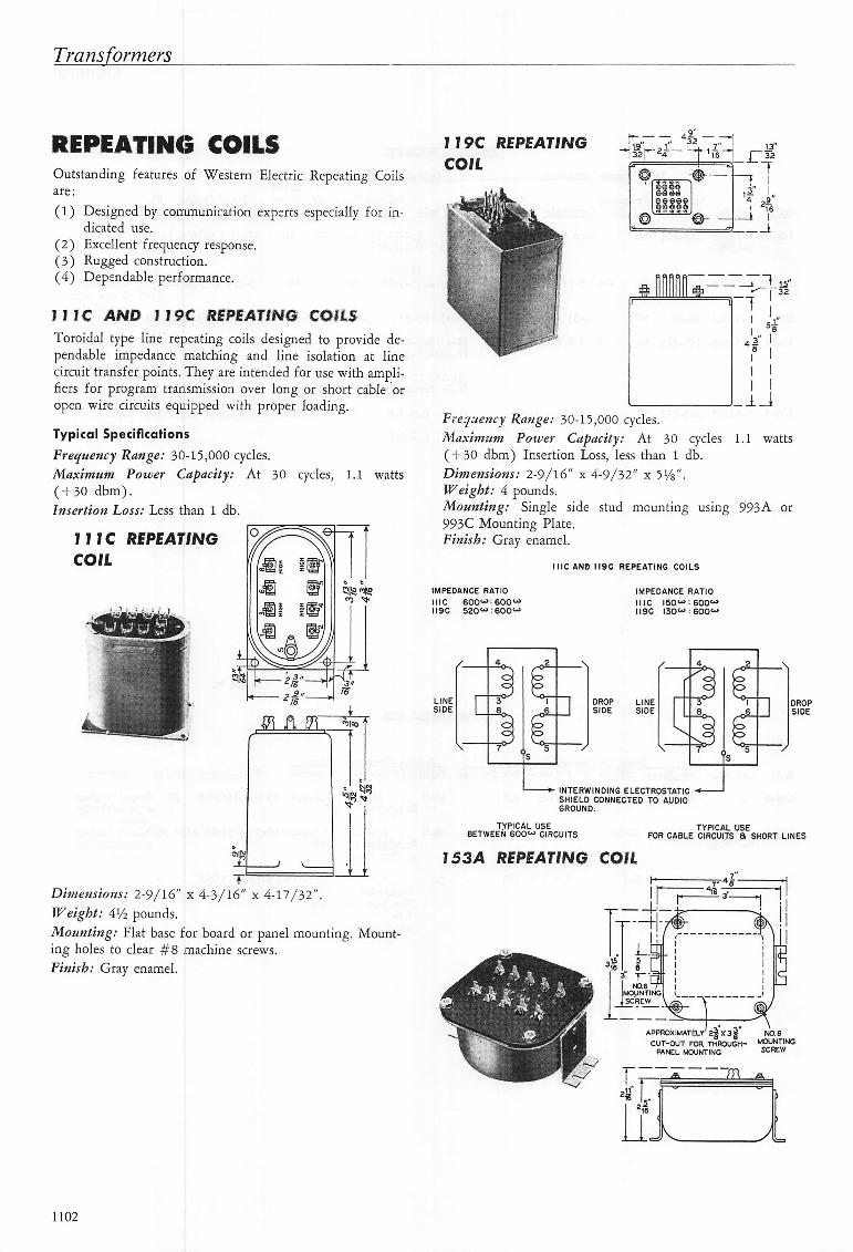
R E P E A T I N G C O I L SOutstanding features of Western Electric Repeating Coilsa r e :
(1) Designed by communication experts especially for indicated use.
(2) Excellent frequency response.(3) Rugged construction.(4) Dependable performance.
f J I C A N D 1 1 9 C R E P E A T I N G C O I L S
Toroidal type line repeating coils designed to provide dependable impedance matching and line isolation at linecircuit transfer points. They are intended for use with amplifiers for program transmission over long or short cable oropen wire circuits equipped with proper loading.
Typical Specifications
Frequency Range; 30-15,000 cycles.Maximum Power Capacity; At 30 cycles, 1.1 watts(-f 30 dbm).Insertion Loss; Less than 1 db.
M I C R E P E A T I N GC O I L
Dimensions; 2-9/16" x 4-3/16" x 4-17/32".Weight; M/z pounds.Mounting; Flat base for board or panel mounting. Mounting holes to clear #8 machine screws.Finish; Gray enamel.
7 7 9 C R E P E A T I N G
C O I L
Frequency Range; 30-15,000 cycles.Maxim-um Power Capacity; At 30 cycles 1.1 watts(-1-30 dbm) Insertion Loss, less than 1 db.Dimensions; 2-9/16" x 4-9/32" x 5Vs".Weight; 4 pounds.Mounting; Single side stud mounting using 993A or993C Mounting Plate.Finish; Gray enamel.
I M P E O A N C E R A T I O
I I I C 6 0 0 ' - » : 6 0 0 "I I 9 C 5 2 0 " : 6 0 0 "
I I I C A N D I I 9 C R E P E A T I N G C O I L S
I M P E D A N C E R A T I O
I I I C I S O " I 6 0 0 "1 1 9 0 1 3 0 " : 6 0 0 "
L I N ES I D E
Oo {
r°^O
o
o
D R O PS I D E
L I N ES I D E
■ INTERWINDING ELECTROSTATIC ■*SHIELD CONNECTED TO AUDIOG R O U N D .
O
D R O PS I D E
T Y P I C A L U S EB E T W E E N 6 0 0 ^ - ' C I R C U I T S
T Y P I C A L U S EF O R C A B L E C I R C U I T S a S H O R T L I N E S
1 5 3 A R E P E A T I N G C O I L
CUT-OUT FOR THROUGH- MOUNTINGP A N E L M O U N T I N G S C R E W
11 0 2
G e n e r a l
A toroidal coil with permalloy core in a flat type mounting,potted in a heavy iron case. Designed for general use inmicrophone or line level circuits to match impedances.A high degree of shielding against unwanted longitudinaltransmission is provided by two electrostatic shields betweenwindings — use separately to segregate grounds or strap toform a single shield.
2 0 C f
_L_
oo
2 0- O - O
ooo
3 0Oo
— o -
4
5- o
30^500"
r -o
Typical Specifications
Frequency Range; 40-15,000 cycles.Maximum Power Capacity: At 30 cycles, 0.226 watts( + 24 dbm).Insert ion Loss; Less than 0.5 db.
Dimensions; 4Vb" x 3-15/16" x 2-11/16" includingt e r m i n a l s .
Weight; 2 pounds, 10 ounces.Mounting; Flat base for board or panel.Finish; Gray enamel.
T 5 4 C R E P E A T I N G C O I L
» — a
a'l:. r s II I
. L - 1
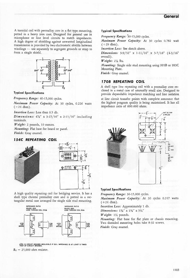
A high quality repeating coil for bridging service. It has ashell type chrome permalloy core and is potted in a rectangular metal case arranged for single side stud mounting.
I M P E D A N C E R A T I O
5 5 4 0 0 : 6 0 0LOSS THROUGH COIL 24<ib
IMPEDANCE RATiO3 0 4 0 0 : 6 0 0L O S S T H R O U G H C O I L i S d b
L O W H I G HI M P . I M PC C T . B R I D G E
Typical Specifications
Frequency Range; 30-15,000 cycles.Maximum Power Capacity; At 30 cycles 0.782 watt( + 29 dbm).Insertion Loss; See sketch above.
Dimensions; 3-9/32" x 1-11/16" x 3-7/16" (4-3/16"overall).Weight; 2% lbs.Mounting; Single side stud mounting using 993B or 993CMounting Plate.Finish; Gray enamel.
I 7 0 B R E P E A T I N G C O I LA shell type line repeating coil with a permalloy core enclosed in a metal case of unusually small size. Designed toprovide dependable impedance matching and line isolationat line circuit transfer points with complete assurance thatthe highest program quality is being maintained. It has allimpedance ratio of 600:600 ohms.
3 l . _ ■-1 /l64'-3a TAP2 HOLES
s M
[
- -nf - r
- J - i
Typical SpecificationsFrequency Range; 30-15,000 cycles.Maximum Power Capacity; At 30 cycles 0.247 watts( + 24 dbm).Insertion Loss; Approximately 1 db.Dimensions; 1%" x 1%" x 314"
Weight; 114 pounds.Mounting; Flat base for flat plate or chassis mounting.Two threaded mounting holes take 8-32 screws.Finish; Gray enamel.
LOSS IN CIRCUIT BRIDGED NEGLIGIBLE IF COIL IMPEDANCE IS AT LEAST 5 TIMESTHAT OF CIRCUIT BRIDGED.
Ri = 25,000 ohm resistor.
1 1 0 3
T r a n s f o r m e r s
I M P E D A N C E R A T I O
6 0 0 " : 6 0 0 ' - > - G R T O B R6 0 0 " ^ : I 5 0 " - G R T O 6 R - W H O R
B R T O S R - W H
I M P E D A N C E R A T I O
I 5 0 « ^ : 6 0 0 V - G R T O B R1 5 0 U > ; ) 5 O W - 6 R T O G R - W H O R
B R T O G R - W H
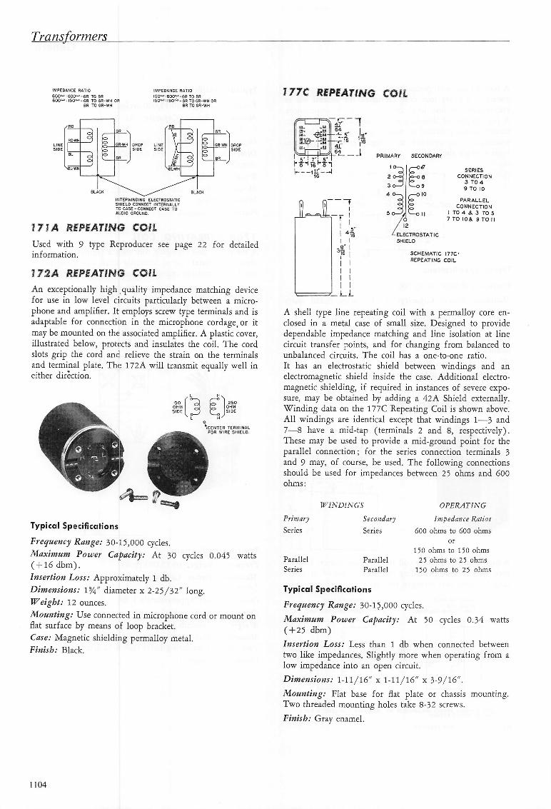
I77C REPEATING COIL
✓ ROG R V
R O W HO o
L I N E G R - W HS I D E 1 o
B L o oB R
o /
^BL-WH
D R O P L I N ES I D E S I D E
G R \
O
o G R - W H
oo
B R
I N T E R W I N O I M G E L E C T R O S T A T I CS H I E L D C O N N E C T I N T E R N A L L YT O C A S E - C O N N E C T C A S E T OA U D I O G R O U N D ,
1 7 1 A R E P E A T I N G C O I L
Used with 9 type Reproducer see page 22 for detailedi n f o r m a t i o n .
1 7 2 A R E P E A T I N G C O I L
An exceptionally high quality impedance matching devicefor use in low level circuits particularly between a microphone and amplifier. It employs screw type terminals and isadaptable for connection in the microphone cordage, or itmay be mounted on the associated amplifier. A plastic cover,illustrated below, protects and insulates the coil. The cordslots grip the cord and relieve the strain on the terminalsand terminal plate. The 172 A will transmit equally well inei ther d i rect ion.
3 0O H M
S I D E
2 5 0O H MS I D E
Ve n t e r t e r m i n a lF O R W I R E S H I E L D .
Typical Specifications
Frequency Range: 30-15,000 cycles.Maximum Power Capacity; At 30 cycles 0.045 watts( + 16 dbm).Insertion Loss: Approximately 1 db.Dimensions: VA" diameter x 2-25/32" long.Weight: 12 ounces.Mounting: Use connected in microphone cord or mount onflat surface by means of loop bracket.Case: Magnetic shielding permalloy metal.F i n i s h : B l a c k .
l lI I
¥ II II 1I II I
_ i _ L
P R I M A R Y
1 O -
2 O-̂3 c
4 (
/fa
S E C O N D A R Y
— O U
) 9
5 10
S E R I E SC O N N E C T I O N
3 T O 49 T O 1 0
P A R A L L E LCONNECTION
I TO 4 3, 3 TO 57 TO lOa. 9 TO ri
^ELECTROSTATICS H I E L D
S C H E M A T I C I 7 7 C 'R E P E A T I N G C O I L
A shell type line repeating coil with a permalloy core enclosed in a metal case of small size. Designed to providedependable impedance matching and line isolation at linecircuit transfer points, and for changing from balanced tounbalanced circui ts. The coi l has a one-to-one rat io.It has an electrostatic shield between windings and anelectromagnetic shield inside the case. Additional electromagnetic shielding, if required in instances of severe exposure, may be obtained by adding a 42A Shield externally.Winding data on the 177C Repeating Coil is shown above.All windings are identical except that windings 1—3 and7—8 have a mid-tap (terminals 2 and 8, respectively).These may be used to provide a mid-ground point for theparallel connection; for the series connection terminals 3and 9 may, of course, be used. The following connectionsshould be used for impedances between 25 ohms and 600o h m s :
W I N D I N G S
PrimarySeries
P a r a l l e lSeries
SecondarySeries
P a r a l l e lP a r a l l e l
O P E R A T I N G
Impedance Ratios600 ohms to 600 ohms
o r
150 ohms to 150 ohms25 ohms to 25 ohms
150 ohms to 25 ohms
Typical Specifications
Frequency Range: 30-15,000 cycles.Maximum Power Capacity: At 50 cycles 0.34 watts( + 25 dbm)Inser t ion Loss : Less than 1 db when connec ted be tweentwo like impedances. Slightly more when operating from alow impedance into an open circuit.Dimensions: 1-11/16" x 1-11/16" x 3-9/16".
Mounting: Flat base for flat plate or chassis mounting.Two threaded mounting holes take 8-32 screws.Finish: Gray enamel.
1 1 0 4