Embed Size (px)
Citation preview
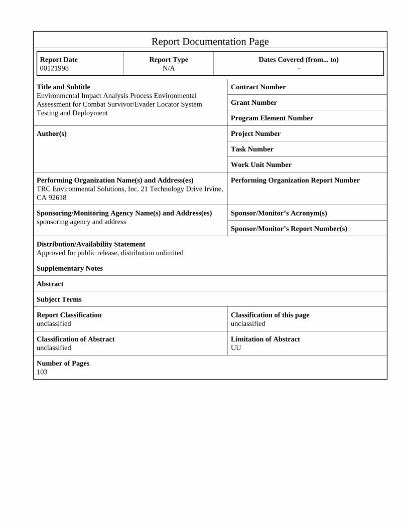
Report Documentation Page
Report Date 00121998
Report Type N/A
Dates Covered (from... to) -
Title and Subtitle Environmental Impact Analysis Process EnvironmentalAssessment for Combat Survivor/Evader Locator SystemTesting and Deployment
Contract Number
Grant Number
Program Element Number
Author(s) Project Number
Task Number
Work Unit Number
Performing Organization Name(s) and Address(es) TRC Environmental Solutions, Inc. 21 Technology Drive Irvine,CA 92618
Performing Organization Report Number
Sponsoring/Monitoring Agency Name(s) and Address(es) sponsoring agency and address
Sponsor/Monitor’s Acronym(s)
Sponsor/Monitor’s Report Number(s)
Distribution/Availability Statement Approved for public release, distribution unlimited
Supplementary Notes
Abstract
Subject Terms
Report Classification unclassified
Classification of this page unclassified
Classification of Abstract unclassified
Limitation of Abstract UU
Number of Pages 103
ENVIRONMENTAL ASSESSMENT FORCOMBAT SURVIVOR/EVADER LOCATORSYSTEM TESTING AND DEPLOYMENTCONTRACT NO. DACW05-96-D-0006DELIVERY ORDER NO. 3
Prepared for
Department of the Air ForceHeadquarters Space and Missile Systems Center/AXFVLos Angeles Air Force Base, California
And
U.S. Army Corps of Engineers - Sacramento DistrictSacramento, California
Prepared by
TRC Environmental Solutions, Inc.
Project No. 97-186December 1998
i
TABLE OF CONTENTS
PAGE NO.
LIST OF TABLES AND FIGURES iv
LIST OF ACRONYMS AND ABBREVIATIONS v
1.0 PURPOSE AND NEED FOR ACTION 1-1
1.1 Background 1-1
1.2 Purpose and Need 1-1
1.3 Decision to Be Made 1-2
1.4 Purpose of the Environmental Assessment 1-2
1.5 Issues 1-4
1.6 Scope of Environmental Assessment 1-5
1.7 Organization of the Environmental Assessment 1-6
2.0 DESCRIPTION OF PROPOSED ACTION AND ALTERNATIVES (DOPAA) 2-1
2.1 Introduction 2-1
2.2 System Description 2-1
2.2.1 User Equipment Segment 2-1
2.2.1.1 Hand-Held Radio 2-2
2.2.1.2 Support Equipment 2-2
2.2.1.3 Battery Pack and Backup Battery 2-2
2.2.2 Over-the-Horizon Relay Component 2-3
2.2.2.1 UHF SATCOM 2-3
2.2.2.2 SARSAT 2-3
2.2.2.3 Commercial System Growth 2-4
2.2.3 Ground Component 2-4
2.2.3.1 UHF SATCOM Base Stations 2-4
2.2.3.2 JSRC 2-7
2.3 Description of the Proposed Action 2-7
2.3.1 Testing and Evaluation 2-7
2.3.1.1 Developmental Testing 2-7
2.3.1.2 Operational Assessment and Operational Testing 2-10

TABLE OF CONTENTS(Continued)
ii
2.4 Full Scale Production, Deployment, Operation, Maintenance, 2-13and Disposal (Life Cycle)
2.4.1 Production and Deployment 2-13
2.4.2 Operation, Maintenance and Disposal 2-14
2.5 Alternatives to the Proposed Action 2-15
2.5.1 No Action Alternative 2-15
2.5.2 Other Alternatives Eliminated From Consideration 2-16
2.5.2.1 Alternative Battery 2-16
2.6 Mitigation Measures 2-16
3.0 AFFECTED ENVIRONMENT 3-1
3.1 Introduction 3-1
3.2 Issues Requiring Environmental Analysis 3-2
3.2.1 Hazardous Materials 3-3
3.2.2 Electromagnetic Radiation 3-3
3.3 Other Potential Environmental Issues Evaluated 3-4
4.0 ENVIRONMENTAL CONSEQUENCES AND CUMULATIVE IMPACTS 4-1
4.1 Introduction 4-1
4.1.1 Hazardous Materials 4-1
4.1.1.1 Proposed Action 4-1
4.1.1.2 No Action Alternative 4-3
4.1.2 Electromagnetic Radiation 4-3
4.1.2.1 Proposed Action 4-3
4.1.2.2 EMR Hazards Criteria 4-4
4.1.2.3 EMR Hazard Analysis 4-4
4.1.2.4 EMR Hazard to Wildlife 4-5
4.1.3 No Action Alternative 4-6
4.2 Other Potential Environmental Issues 4-6
5.0 REGULATORY REVIEW AND PERMIT REQUIREMENTS 5-1
5.1 Introduction 5-1
TABLE OF CONTENTS(Continued)
iii
6.0 PERSONS AND ORGANIZATIONS CONSULTED OR 6-1THAT PROVIDED INFORMATION
7.0 REFERENCES 7-1
APPENDIX A: AIR FORCE FORM 813 - CSEL PROGRAM
APPENDIX B: AIR FORCE FORM 813 - WOODLAND COUGAR 1997 - PERSONNELRECOVERY EXERCISE
APPENDIX C: U.S. ARMY COMMUNICATIONS - ELECTRONICS COMMANDENVIRONMENTAL IMPACT ANALYSIS WORKSHEET - OPERATIONALTESTING OF CSEL SYSTEM.
APPENDIX D: MATERIAL SAFETY DATA SHEET (MSDS) - LiSO2 BATTERY
APPENDIX E: CSEL ELECTROMAGNETIC RADIATION (EMR) HAZARD ANALYSIS -CAMP SMITH, HAWAII
TABLE OF CONTENTS(Continued)
iv
LIST OF FIGURES
FIGURE NO. TITLE PAGE NO.
1.1 System Architecture 1-3
2.1 Ground Segment 2-5
2.2 Operational UHF SATCOM Base Station Location 2-6
2.3 Developmental Testing Locations 2-9
2.4 Operational Assessment Locations 2-11
v
LIST OF ACRONYMS AND ABBREVIATIONS
AAA Anti-Aircraft Artillery
AFB Air Force Base
AFI Air Force Instruction
AFOSH Air Force Occupational Safety and Health
AFOTEC Air Force Test and Evaluation Center
ACGIH American Conference of Government Industrial Hygienist
BOEING Boeing North American
CATEX Categorical Exclusion
CED Concept Exploration and Definition
CEQ Council on Environmental Quality
CSEL Combat Survivor/Evader Locator
DoD Department of Defense
DOPAA Description of the Proposed Action and Alternatives
EA Environmental Assessment
EIAP Environmental Impact Analysis Process
EMC Electromagnetic Compatibility
EMR Electro-Magnetic Radiation
FONSI Finding of No Significant Impact
FY Fiscal Year
GPS Global Position System
IEEE Institute of Electrical Electronics Engineers
JROC Joint Requirements Oversight Council
JSRC Joint Search and Rescue Center
LiSO2 Lithium-Sulfur Dioxide
MSDS Material Safety Data Sheet
N/A Not Applicable
NEPA National Environmental Policy Act
OSHA Occupational Safety and Health Administration
PBD Program Budget Decision
PEL Permissible Exposure Level
RF Radio Frequency
SAM Surface-to-Air Missile
SARSAT Search & Rescue Satellite Assisted Tracking
SATCOM Satellite Communication
UHF Ultra High Frequency
USAF U.S. Air Force

SECTION 1.0
PURPOSE AND NEED FOR ACTION
1-1
1.0 PURPOSE AND NEED FOR ACTION
1.1 BACKGROUND
1. The Department of Defense (DoD) currently relies on the PRC-90 and the PRC-112 standard
issue survival radios to assist search and rescue forces to locate downed pilots and other
isolated personnel. The design of these radios is 15-30 years old and exhibit key
shortcomings that can be overcome by current technology. In January 1992, as a result of
lessons learned in Desert Storm, the Joint Requirements Oversight Council (JROC) approved
the mission need statement for the Combat Survivor/Evader Locator (CSEL) program. CSEL
Milestone 0 approval was issued in August 1992.
2. The CSEL program completed its Concept Exploration and Definition (CED) Phase in Fiscal
Year (FY) 1994. This phase included the following:
• Contracted and in-house concept studies that developed a variety ofalternative solutions for the CSEL Cost and OperationalEffectiveness Analysis.
• Survey of commercial communications capabilities.
• Development and approval of an Operational Requirements Document.
• Development of a CSEL Operations Concept.
• Selection of a proposed concept for further developmentand demonstration.
• Formulation of a proposed implementation plan.
• Development of the detailed plan for demonstrating and defining thesystem and segment requirements for the proposed CSEL concept.
However, approval to move CSEL into the next phase was not pursued by DoD due to the high
cost of the potential solutions.
1.2 PURPOSE AND NEED
1. Events in Bosnia, specifically the downing of Captain Scott O’Grady in May 1995, highlighted
the need to resume development of the CSEL program and resulted in Program Budget
Decision (PBD) No. 228, based on a September 21, 1995 memorandum between the Secretary
of Defense and the Director, Central Intelligence, that directed the development and
procurement of an improved combat search and rescue radio that fulfills the CSEL mission
need statement. The PBD provided for the procurement of CSEL radios beginning 18 months
1-2
after the award of an EMD contract. Radio deliveries for all DoD services are proposed to
begin at 500 in FY 1998 and ramp up to 8,000 in FY 2000, for a total of 27,000 units
by FY 2002.
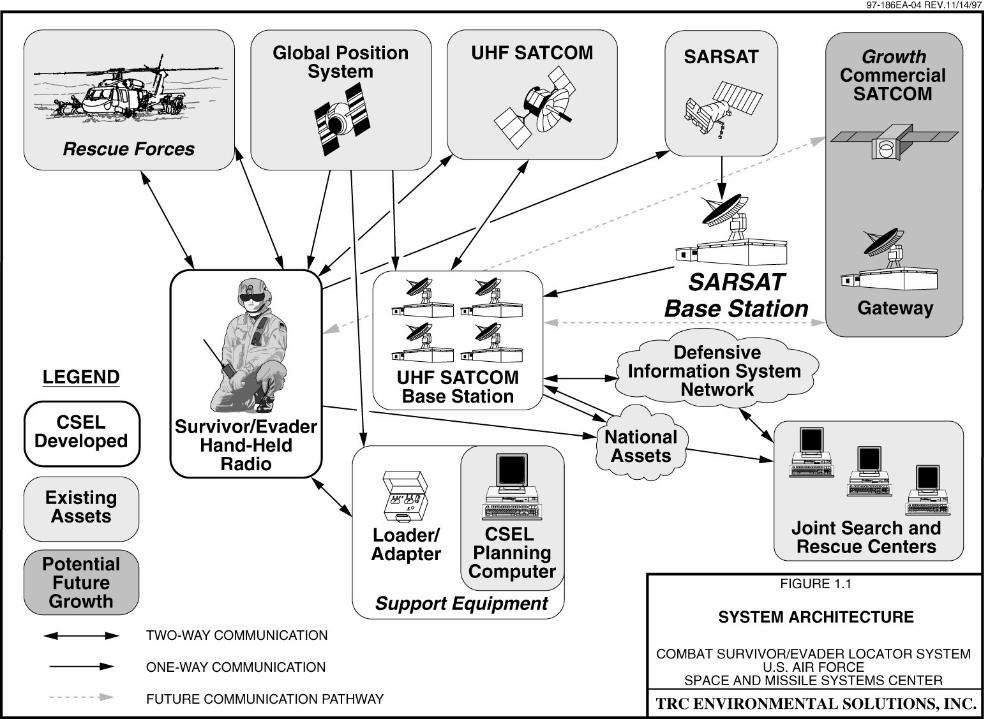
2. The CSEL system has been designed to provide global over-the-horizon data communications,
line-of-sight voice communications, and precise Global Position System (GPS) positioning
capabilities for DoD personnel when they are confronted with survival and/or evasion
scenarios in peacetime and conflict situations. The CSEL system is composed of three
components: User Equipment, Over-the-Horizon Relay, and Ground System. Figure 1.1
shows the three components of the CSEL system.
3. To assure the operational suitability and effectiveness of the CSEL system before deployment
in FY 1998, Developmental Testing and an Operational Assessment program will be conducted
using 35 production CSEL hand-held radios. The results of these tests will be used to fine-
tune the system design and provide data for a decision regarding production.
1.3 DECISION TO BE MADE
The decision to be made regarding the CSEL program is to whether to:
• Proceed with production and deployment of the CSEL system and itsassociated infrastructure.
• Take no action (i.e., No Action Alternative) and continue to rely upon theexisting combat search and rescue system and hardware.
1.4 PURPOSE OF THE ENVIRONMENTAL ASSESSMENT
The purpose of this Environmental Assessment (EA) is to provide information to the U.S. Air
Force (USAF) decision maker(s) regarding the potential environmental consequences of the
proposed action and alternatives, including the No Action alternative. The information
included in this EA will be considered, along with other technical and mission needs
information regarding the CSEL program, in making decisions regarding the program.
1-4
1.5 ISSUES
1. This EA analyzes the potential environmental issues associated with the Developmental Testing
and Operational Assessment of 35 production CSEL radios by DoD personnel at various
existing DoD facilities, and the proposed production, deployment, operation, maintenance, and
disposal of the CSEL system and its associated infrastructure worldwide. The following
factors were considered in determining the range of issues addressed in this EA:
• As discussed in detail in Chapter 2.0 of this EA, Developmental Testing ofthe CSEL hardware and infrastructure system will be conducted at variousexisting DoD facilities whose ongoing missions include the testing andanalysis of electronic equipment and systems. This includes bothlaboratory based testing and field testing by DoD and governmentalcontractor personnel. Therefore, the Developmental Testing of the CSELsystem at existing DoD facilities is considered part of the baselineenvironmental condition at the facilities and does not require additionalenvironmental analysis as part of the CSEL program.
• As discussed in detail in Chapter 2.0 of this EA, the OperationalAssessment and Operational Testing program for the CSEL systemincludes deployment of DoD personnel at various existing DoD facilitiesas part of routine or annual training exercises. These personnel will use35 CSEL hand-held radios as part of routine search and rescue exercises,with the only difference being the use of the CSEL hand-held radios ratherthan standard issues search and rescue radios. Therefore, with theexception of testing new equipment, the deployment of personnel atvarious DoD facilities is part of the existing mission of the facilities, and isconsidered part of the baseline environmental condition of the facilities anddoes not require additional environmental analysis as part of the CSELprogram.
• As shown in Figure 1.1, the majority of the CSEL system are existingDoD assets that can accommodate the additional mission requirements ofthe CSEL program without upgrades or expansions. The two newcomponents of the program are the CSEL hand-held radio and thetransmitting/receiving antennas that will be installed as part of theUHF SATCOM Base Stations at four existing Naval Computer andTelecommunications Area Master Stations. The antennas will be installedas part of existing communication arrays at the existing stations, and arethe same type and model of antennas that are already deployed at thestations for other DoD missions.
2. Through this evaluation of potential environmental issues associated with testing, production,
deployment, operation, maintenance, and disposal of the CSEL system, the two following
specific issues were identified that require environmental analyses, and are the focus of
this EA:
• The CSEL hand-held radio is powered by a lithium sulfur dioxide (LiSO2)battery pack that was selected for the CSEL program because it provideslonger battery life over a wider temperature range than conventionalalkaline batteries. While specific safe guards have been designed into thebattery case and the battery pack itself, in the event of an uncontrolled
1-5
venting during field-use, maintenance, storage, and/or disposal, the LiSO2battery pack has the potential to emit hot toxic sulfur dioxide vapors. ThisEA analyzes the potential environmental consequences of uncontrolledventing of the battery pack.
• The transmitting/receiving antennas that will be installed as part of theUHF SATCOM Base Stations at four existing Naval Computer andTelecommunications Area Master Stations, and two similar antennas thatwill be installed to support the CSEL Operational Assessment programemit low level electro-magnetic radiation (EMR) that has the potential toresult in human health and safety risks. This EA analyzes the potentialhuman health and safety consequences associated with the EMR generatedby the CSEL transmitting/receiving antennas.
3. With the exception of the potential environmental consequences associated with the
uncontrolled venting of the LiSO2 battery pack and the EMR from the transmitting/receiving
antennas, the testing, production, deployment, operation, maintenance, and disposal of the
CSEL hardware and infrastructure on a world-wide basis does not have the potential to result
in environmental consequences.
1.6 SCOPE OF ENVIRONMENTAL ASSESSMENT
1. This EA is part of USAF's Environmental Impact Analysis Process (EIAP) for the proposed
CSEL program. The requirements for the EIAP are included in Air Force Instruction
(AFI) 32-7061, Environmental Impact Analysis Process, which implements the National
Environmental Policy Act (NEPA) and the President's Council on Environmental Quality
(CEQ) regulations for complying with NEPA. Additional EIAP requirements are included in
DoD Directive 6050.1, Mandatory Procedures for Major Defense Acquisition Programs; and
Air Force Policy Directive 32-70, Environmental Quality.
2. This EA evaluates the potential environmental consequences of the full range of activities
associated with the proposed action and the reasonable alternatives to the proposed action,
including the No Action alternative. In accordance with AFI 32-7061, NEPA, and CEQ
regulations, this EA:
• Describes the existing baseline environmental conditions as related to theproposed action.
• Identifies and analyzes the potential environmental consequences of theproposed action and the resulting environmental impacts and cumulativeenvironmental impacts.
1-6
• Identifies mitigation measures, as appropriate, to eliminate, limit or reducethe potential environmental impacts associated with the proposed actionand its alternatives.
• Identifies applicable environmental permits, if any, that may be required forthe proposed action.
3. Applicable CSEL program and environmental data were collected and analyzed to document
the potential environmental consequences of the proposed action and alternatives. This data
included the Request for Environmental Analysis (Air Force Form 813) and the Description of
the Proposed Action and Alternatives (DOPAA) for the CSEL program dated May 19, 1997
(see Appendix A). The Air Force Form 813 determined that the program did not qualify for a
Categorical Exclusion (CATEX) and that additional environmental analysis was required.
4. In accordance with NEPA and CEQ regulations, the USAF is required to determine the
environmental impacts of its proposed actions and its alternatives. If, upon review of this EA
and other technical and mission information regarding the CSEL program, the USAF decision
makers approve the findings and conclusion of this EA that the potential environmental
impacts from the CSEL program are not significant, the USAF decision makers will approve a
Finding of No Significant Impact (FONSI).
1.7 ORGANIZATION OF THE ENVIRONMENTAL ASSESSMENT
1. The remainder of this EA is organized in the following Chapter format:
• Chapter 2.0: Description of the Proposed Action and Alternatives (DOPAA).• Chapter 3.0: Affected Environment• Chapter 4.0: Environmental Consequences and Cumulative Impacts• Chapter 5.0: Regulatory Review and Permit Requirements• Chapter 6.0: Persons and Organizations Consulted/That Provided Information• Chapter 7.0: References• Chapter 8.0: List of Prepares• Appendices:
- Appendix A: Air Force Form 813 - CSEL Program- Appendix B: Air Force Form 813 - Woodland Cougar
1997-Personnel Recovery Exercise- Appendix C: U.S. Army Communications - Electronics
Command Environmental Impact Analysis Worksheet -Operational Testing of CSEL System
- Appendix D: Material Safety Data Sheet (MSDS) - LiSO2 Battery- Appendix E: CSEL Electromagnetic Radiation (EMR) Hazards
Analysis - Camp Smith, Hawaii

SECTION 2.0
DESCRIPTION OFPROPOSED ACTION AND ALTERNATIVES
2-1
2.0 DESCRIPTION OF PROPOSED ACTIONAND ALTERNATIVES (DOPAA)
2.1 INTRODUCTION
1. This chapter provides the DOPAA for the CSEL system life cycle including the Developmental
Testing and Operational Assessment, production, deployment, operation, maintenance, and
disposal of the CSEL system. This chapter also includes a description of the alternatives to the
proposed action, including the No Action alternative.
2. The CSEL system has been designed to provide global over-the-horizon data communications,
line-of-sight voice communications, and precise GPS positioning capabilities for DoD
personnel when they are confronted with survival and/or evasion scenarios in peacetime and
conflict situations. The CSEL system is composed of three components: User Equipment,
Over-the-Horizon Relay, and Ground Systems (see Figure 1.1).
3. If the program is approved, deployment includes the delivery of CSEL hand-held radios to
DoD units beginning with 500 radios in FY 1998, and increasing up to 8,000 radios in FY
2000, for a total of 27,000 radios by FY 2002. To assure the operational suitability and
effectiveness of the CSEL system before deployment, Developmental Testing and an
Operational Assessment program will be conducted using 35 production CSEL hand-held
radios. The results of these tests will be used to fine-tune the system design and provide data
for a decision regarding production.
2.2 SYSTEM DESCRIPTION
2.2.1 USER EQUIPMENT SEGMENT
1. As shown in Figure 1.1, the User Equipment segment of the CSEL program consists of the
hand-held radios provided to DoD personnel who may be faced with a survival or evasion
situation. The hand-held radios are supported by the CSEL Planning Computers to load
mission specific information into the radio prior to a mission, and Loader/Adapters that serve
as an interface between the CSEL Planning Computers and the hand-held radios. The
following sections provide an overview of the User Equipment components.
2-2
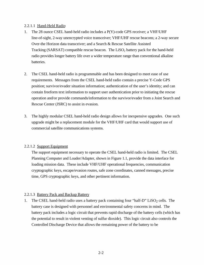
2.2.1.1 Hand-Held Radio
1. The 28 ounce CSEL hand-held radio includes a P(Y)-code GPS receiver; a VHF/UHF
line-of-sight, 2-way unencrypted voice transceiver; VHF/UHF rescue beacons; a 2-way secure
Over-the Horizon data transceiver; and a Search & Rescue Satellite Assisted
Tracking (SARSAT) compatible rescue beacon. The LiSO2 battery pack for the hand-held
radio provides longer battery life over a wider temperature range than conventional alkaline
batteries.
2. The CSEL hand-held radio is programmable and has been designed to meet ease of use
requirements. Messages from the CSEL hand-held radio contain a precise Y-Code GPS
position; survivor/evader situation information; authentication of the user’s identity; and can
contain freeform text information to support user authentication prior to initiating the rescue
operation and/or provide commands/information to the survivor/evader from a Joint Search and
Rescue Center (JSRC) to assist in evasion.
3. The highly modular CSEL hand-held radio design allows for inexpensive upgrades. One such
upgrade might be a replacement module for the VHF/UHF card that would support use of
commercial satellite communications systems.
2.2.1.2 Support Equipment
The support equipment necessary to operate the CSEL hand-held radio is limited. The CSEL
Planning Computer and Loader/Adapter, shown in Figure 1.1, provide the data interface for
loading mission data. These include VHF/UHF operational frequencies, communication
cryptographic keys, escape/evasion routes, safe zone coordinates, canned messages, precise
time, GPS cryptographic keys, and other pertinent information.
2.2.1.3 Battery Pack and Backup Battery
1. The CSEL hand-held radio uses a battery pack containing four “half-D” LiSO2 cells. The
battery case is designed with personnel and environmental safety concerns in mind. The
battery pack includes a logic circuit that prevents rapid discharge of the battery cells (which has
the potential to result in violent venting of sulfur dioxide). This logic circuit also controls the
Controlled Discharge Device that allows the remaining power of the battery to be
2-3
discharged to assure safe storage, transport and disposal of expended batteries. In addition, the
case has strategically-placed “pressure points” that are designed to guide hot toxic vapors
(i.e., sulfur dioxide) away from the operator in the unlikely event of a venting incident.
2. LiSO2 battery chemistry is the most significant environmental and safety concern related to
CSEL program. For this reason, a major part of the Developmental Testing program for the
CSEL system is focused on certifying the battery for use by all three DoD services: Army,
Navy and Air Force.
3. The CSEL hand-held radio also contains a backup coin-cell battery that is used to keep key
components of radio's memory "alive "when the main battery pack is removed for maintenance.
The battery used for this backup function is a commercially-available lithium, coin-cell battery
(model number CR1620) that can be handled like any other commercially-available lithium
battery.
2.2.2 OVER-THE-HORIZON RELAY COMPONENT
The Over-the-Horizon Relay component includes two Satellite Communication (SATCOM)
systems to provide total Earth coverage. These two systems are the Ultra High Frequency
(UHF) SATCOM and SARSAT. Jointly these two satellite systems provide continuous
world-wide, over-the-horizon coverage.
2.2.2.1 UHF SATCOM
The UHF SATCOM supports 2-way messaging/geolocation between the survivor/evader with
a hand-held radio and one of four proposed UHF SATCOM Base Station that will be
installed at four existing Naval Computer and Telecommunications Area Master Stations. The
UHF SATCOM Base Station includes a transmitting/receiving antenna which will be installed
as part of existing communication arrays at the existing stations. The antennas are the same
type and model already deployed at the stations for other DoD missions.
2.2.2.2 SARSAT
The SARSAT mode operates over the international SARSAT Low Earth Orbit satellite system
and is intended for emergency coverage above 70o latitudes where UHF SATCOM and
2-4
National Asset coverage may be lacking. Unencrypted CSEL transmissions via SARSAT are
received at the U.S. Mission Control Center, processed, and forwarded to a UHF SATCOM
Base Station for routing to the appropriate JSRC.
2.2.2.3 Commercial System Growth
The CSEL System architecture is designed for future growth to include a commercial satellite
link, when available. Commercial satellite communication services allow CSEL to become
independent of the heavily used UHF SATCOM satellites. The system does not currently
accommodate commercial satellite services.
2.2.3 GROUND COMPONENT
2.2.3.1 UHF SATCOM Base Stations
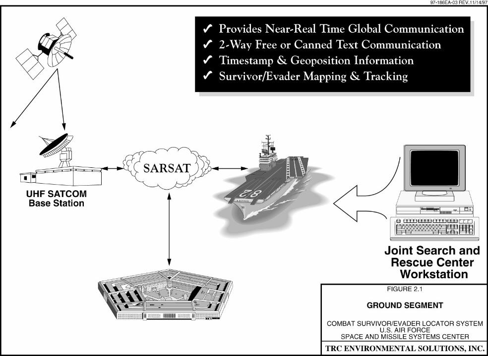
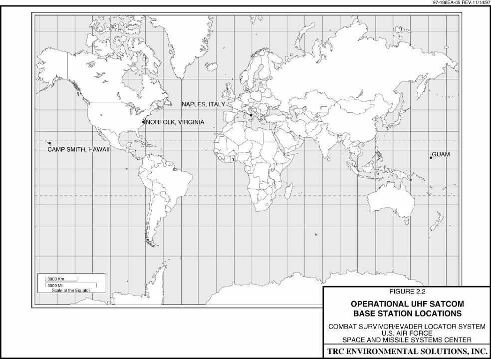
1. The ground segment of the CSEL program includes the UHF SATCOM Base Stations and
JSRC computer terminal, see Figure 2.1. The UHF SATCOM Base Stations will be installed
at four world-wide locations, as shown in Figure 2.2. The four Base Stations will be collocated
at existing Naval Computer and Telecommunications Area Master Station facilities. The UHF
SATCOM Base Stations receive and transmit CSEL encrypted messages that are relayed
to/from users via the UHF SATCOM satellites.
2. The CSEL UHF SATCOM Base Stations equipment consists of a UHF SATCOM transceiver
(AN/WSC-3 [v 9]), a rack-mounted computer with custom UHF SATCOM signal processing
software, routing database and messaging software that delivers messages back and forth to the
appropriate JSRC computer terminal. The computer performs the UHF SATCOM command
and control functions and executes the messaging software. The Base Station hardware and
software are configured in two duplicate racks with one acting as a primary and the other as a
hot backup to provide redundancy. CSEL communications data are encrypted to provide data
security with a primary and backup encryption key provided to each user.
2-7
2.2.3.2 JSRC
The existing/evolving Defense Information System Network interconnects the four UHF
SATCOM Base Stations with the world-wide network of JSRCs. The JSRC is the hub of the
CSEL system from a command and control perspective, performing data distribution and
information flow to search and rescue personnel. The JSRC computer terminals provide
CSEL data receiving, display, and data dissemination. The JSRC computer terminal displays
provide the capability to read incoming messages received from the CSEL hand-held radios.
The incoming message received by the JSRC terminal provide the survivor/evader identification
and authentication, location, status, time of message transmission, time of last GPS fix, time of
message receipt, data type, frequency, and the Over-the-Horizon asset in use to the JSRC
operator.
2.3 DESCRIPTION OF THE PROPOSED ACTION
The following sections describe the proposed testing and evaluation of the CSEL system and
its components at DoD facilities and, if approved, the production, deployment, operation,
maintenance, and disposal of CSEL system and infrastructure to DoD units world-wide.
2.3.1 TESTING AND EVALUATION
To support CSEL's Developmental Testing and Operational Assessment program, 30 hand-held
radios and six Loader/Adapters will be fabricated by government contractors that includes
Boeing North American (Boeing) as the prime system contractor. An additional five CSEL
hand-held radios will be built and used by government contractors for their own testing. In
addition to hand-held radios and Loader/Adapters, government contractors will deliver four
Sun Ultra workstations loaded with the CSEL JSRC software, CSEL Panning Computer
software to be loaded on computer workstations, and six racks of equipment at the two UHF
SATCOM Base Station that will support the operational testing.
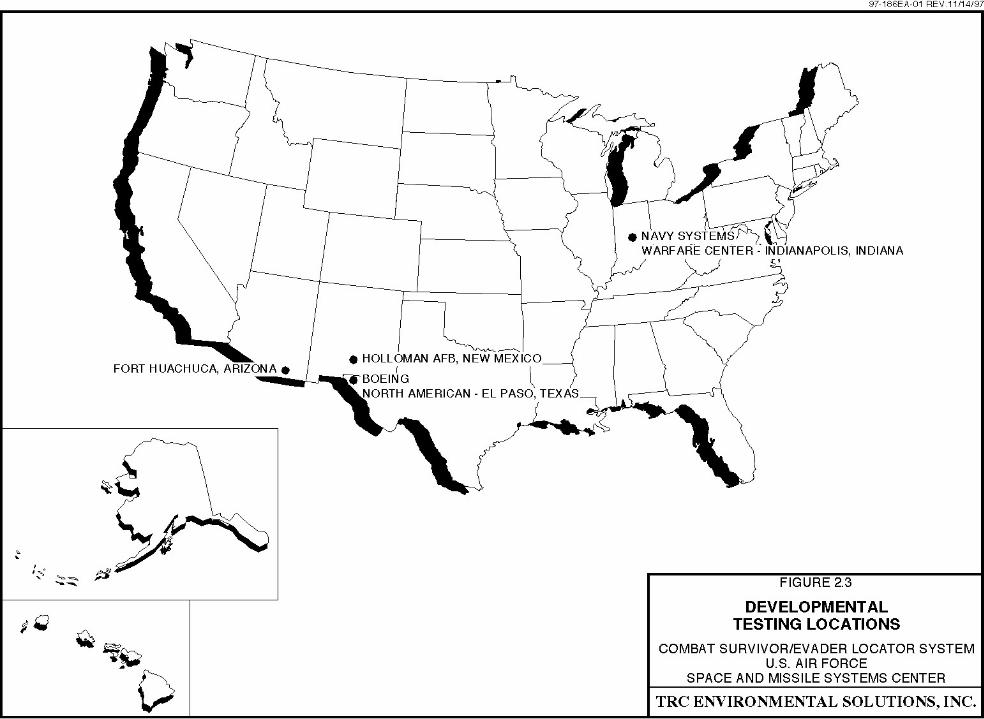
2.3.1.1 Developmental Testing
Developmental Testing of the CSEL system will be performed to measure system performance
to specification requirements. Developmental Testing will be performed by trained personnel
at various, existing DoD test centers, including: Fort Huachuca, Arizona; Holloman Air Force
Base (AFB), New Mexico; and the Navy Systems Warfare Center in Indianapolis, Indiana, as
shown in Figure 2.3. In addition, Developmental Testing, Acceptance Testing, and
2-8
Qualification Testing will be performed by government contractor and subcontractors at
their facilities. The following paragraphs provide an overview of the CSEL Developmental
Testing program.
Army Electronic Proving Grounds, Fort Huachuca, Arizona
Personnel at the Army Electronic Proving Grounds will perform testing on the CSEL
hand-held radio to test radiated power, link margin and bit error rates. Software for the
hand-held radio, CSEL Planning Computer, JSRC and UHF SATCOM Base Stations will be
tested for ease of use.
746th Test Squadron, Holloman , New Mexico
The 746th Test Squadron is the Responsible Test Organization for coordination of the CSEL
Developmental Testing program. In addition to administering the integrated
(government/contractor) Developmental Testing plan, the 746th will conduct the GPS-related
testing and acceleration survivability testing of the CSEL system.
Navy Systems Warfare Center, Indianapolis, Indiana
The Navy Systems Warfare Center is responsible for the safety certification testing for the
LiSO2 battery. The Navy will perform tests to determine the battery’s ability to withstand
extreme conditions in the hands of operators. This certification program will include tri-service
requirements for battery safety.
Boeing North American and Associated Sub-Contractors
Testing at the component, module, and system level is on-going at the government contractors'
sites throughout the development process. Contractor Developmental Testing includes the use
of brassboards, workbench prototypes, analysis and simulation. In addition to Developmental
Testing, the government contractors are involved in formal Qualification Testing and
Acceptance Testing to demonstrate compliance with CSEL program parameters.
2-10
2.3.1.2 Operational Assessment and Operational Testing
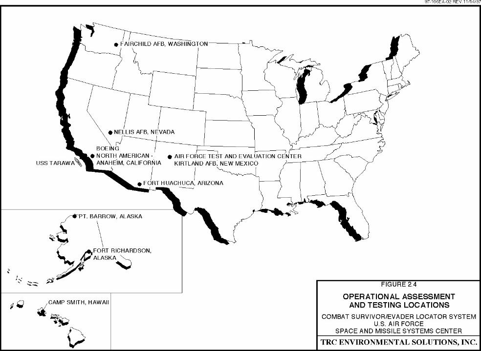
1. Operational Assessment and Operational Testing of the CSEL system will be coordinated by
the Air Force Test and Evaluation Center (AFOTEC) at Kirtland AFB, New Mexico. As the
responsible agency for the Operational Assessment and Operational Testing of the CSEL
system, AFOTEC will coordinate resources, tri-service participation in the assessment program,
locations of test events, test objectives and pass/fail criteria. The Operational Assessment and
Operational Testing locations are shown in Figure 2.4.
2. The primary purpose of the Operational Assessment and Operational Testing is to provide an
independent DoD assessment of the CSEL system under various field and operational
scenarios. Consequently, the operational testing is conducted with “operators” instead of
engineers, contractors and program managers.
Operational Assessment and Operational Testing Scenarios
1. The Operational Assessment and Operational Testing of the CSEL system will consist of field
scenarios that will be executed multiple times to provide an accurate characterization of the
system’s effectiveness and operational suitability. Variations in the field scenarios for
differing environmental conditions (e.g., darkness, foliage, terrain, precipitation, low
temperatures, water, etc.) are incorporated into the test plan. The field scenarios will be
conducted by DoD operational personnel in Alaska, Nevada, Washington and Hawaii as part
of current training exercises or as part of the routine testing and evaluation mission of the DoD
facilities involved. No dedicated range support is required for the CSEL Operational
Assessment and Operational Testing program.
2. To support the field scenarios, the equipment for two UHF SATCOM Base Stations will be
installed at existing facilities. The Base Station equipment will be installed at Camp Smith,
Hawaii and at Boeing's Anaheim, California facility (see Figure 2.4). Equipment installed at
these two sites will include the UHF SATCOM transceiver (AN/WSC-3 [v 9]), a
rack-mounted computer with UHF SATCOM signal processing software, routing database and
messaging software that delivers messages back and forth to the JSRC computer terminals.
Both Camp Smith, Hawaii and Boeing's Anaheim, California facility currently support various
programs that include transceivers of the same type as will be installed for the CSEL system.
2-12
3. The CSEL system Operational Assessment and Operational Testing program includes three
field scenarios that will be implemented by DoD personnel at each of the testing locations.
The field scenarios were specifically designed to represent the operating environment that is
envisioned for the CSEL system and the DoD personnel that will rely upon the system for
search and rescue. The three field scenarios are as follows:
• Scenario 1 - Ground Team Extraction: This scenario involves rescueof aircrew members shot down over hostile territory. The scenariosimulates search and rescue activities behind the "Forward Edge" of the"Battle Area" in a simulated high threat environment. Threats to the searchand rescue force include: surface-to-air missiles (SAM), anti-aircraftartillery (AAA), and small arms fire from enemy troop concentrations.Collateral threats include communications radio monitoring and directionfinding to locate communications emissions.
• Scenario 2 - Search and Rescue Task Force: This scenario involves therescue of two aircrew members shot down over hostile territory by aSearch and Rescue Task Force assembled from DoD operational forceelements in the area. The scenario simulates the successfully ejection oftwo crew members that land approximately one mile apart behind hostile ina high threat environment. One of the crew members is injured and cannotmove.
• Scenario 3 - Opportunity Search and Rescue: This scenario involvesthe rescue of two aircrew members from a ground or water environment.
Operational Assessment and Operational Testing Locations
1. The CSEL system Operational Assessment and Operational Testing will be conducted at
various DoD facilities, as shown in Figure 2.4. Most of the data collected for assessment of
the CSEL system will come from either combined testing or dedicated operational testing in the
field. Developmental Test data will include data from battery safety tests and hand-held radio
environmental tests. The majority of combined testing will be conducted at the Army’s
Electronic Proving Ground at Fort Huachuca. Data on jamming, data communications, and
GPS accuracy/time to fix will be collected during combined testing. Other assessment areas
will be addressed in both combined and dedicated field testing.
2. The field scenarios discussed above will be conducted at various locations to adequately
exercise the Over-the-Horizon capabilities of the system. The field scenarios will be supported
from various locations including Fort Richardson and Point Barrow, Alaska; Camp Smith,
Hawaii; Fairchild AFB, Washington; Boeing’s Anaheim, California facility, and a U.S. Navy
ship that will be off the west coast. To support the field scenarios, there will be four JSRC
sites, two UHF SATCOM Base Stations (Camp Smith, Hawaii and Boeing's Anaheim,
California facility), and at least 18 hand-held radio involved in the field testing.
2-13
3. Operators will be located at various sites including Hawaii and Alaska. They will be comprised
of Rescue Center operators, UHF SATCOM Base Station operators, hand-held radio users
(mock survivors), and CSEL Planning Computer operators. JSRC Workstation operators will
be located in four locations: Fort Belvoir, Virginia; Fort Richardson, Alaska; Pacific Rescue
Coordination Center, Honolulu, Hawaii; and aboard a U.S. Navy ship off the west coast.
4. Finally, survivors/evaders and CSEL Planning Computer operators will be dispersed over
multiple locations, including Kirtland AFB, New Mexico; Nellis AFB, Nevada;
Fort Richardson and Point Barrow Alaska; Camp Smith, Hawaii; Fort Huachuca, Arizona; and
Fairchild AFB, Washington.
2.4 FULL SCALE PRODUCTION DEPLOYMENT, OPERATION, MAINTENANCE,
AND DISPOSAL (LIFE CYCLE)
2.4.1 PRODUCTION AND DEPLOYMENT
1. If full scale production and deployment of the CSEL system is approved, 27,000 CSEL
hand-held radios and their various components will be manufactured at government contractor
and sub-contractor facilities at various locations. The delivery of CSEL hand-held radios to
DoD units will begin with 500 radios in FY 1998, and increasing up to 8,000 radios in
FY 2000 for a total of 27,000 radios by FY 2002.
2. The production of the CSEL system components will take place in existing contractor facilities
designed and permitted for the manufacture of electronic hardware and the various supporting
components. There are various contractors and sub-contractors involved in the development,
manufacturing and integration processes for the CSEL program, with the prime contractor
being Boeing.
3. The operational equipment for the UHF SATCOM Base Stations will be installed at four
existing locations, as shown in Figure 2.2. The equipment for the Base Stations will be
2-14
collocated at four existing Naval Computer and Telecommunications Area Master Station
facilities. The UHF SATCOM Base Stations receive and transmit CSEL encrypted messages
that are relayed to/from users via the UHF SATCOM satellites.
4. The CSEL UHF SATCOM Base Stations equipment consists of a UHF SATCOM transceiver
(AN/WSC-3 [v 9]), a rack-mounted computer with custom UHF SATCOM signal processing
software, routing database and messaging software that delivers messages back and forth to the
appropriate JSRC computer terminal. The computer performs the UHF SATCOM command
and control functions and executes the messaging software.
5. As the CSEL hand-held radios become available, they will be deployed to DoD operational
units world-wide. Deployment is scheduled to begin in FY 1998 and will be completed in
FY 2002. During this period, both the CSEL system and existing standard issues survival
radios will be used. Once deployed, the CSEL hand-held radio system will be used by DoD
personnel when they are confronted with survival and/or evasion in peacetime and
conflict situations.
2.4.2 OPERATION, MAINTENANCE AND DISPOSAL
1. The CSEL system, including the four UHF SATCOM Base Stations world-wide, will begin
operations in FY 1998 when the first CSEL hand-held radios are scheduled for deployment.
Routine operations include the use of the CSEL support equipment to load mission specific
information into the hand-held radios prior to DoD personnel use, in peacetime or
conflict situations.
2. The operation of the CSEL specific equipment at the UHF SATCOM Base Stations will be
handled by DoD personnel at the four existing Naval Computer and Telecommunications Area
Master Stations. The operators of the Base Station equipment will relay information from
DoD personnel using the CSEL system to appropriate DoD search and rescue forces using the
world-wide network of JSRC workstations deployed as part of the system.
3. Maintenance of the CSEL system includes routine maintenance of the supporting electronic
equipment at the UHF Base Stations and of the JSRC workstations. Maintenance will also be
conducted on the CSEL hand-held radios to assure their proper operation. The maintenance of
the hand-held radios includes the testing and replacement of the LiSO2 batteries on a regular
basis to assure the batteries are fully charged and operational.
2-15
4. When the batteries in a hand-held radio require replacement, DoD or contractor maintenance
personnel will activate the Controlled Discharge Device that allows the remaining power of the
battery to be discharged to assure safe removal, storage, transport and disposal of expended
batteries. As part of Developmental Testing program for the CSEL system, the Navy Systems
Warfare Center will develop specific procedures for the handling, maintenance, storage,
transport and disposal of the LiSO2 batteries. Personnel responsible for maintenance and
disposal of the LiSO2 batteries shall be trained as to the proper handling and disposal
procedures.
5. As with the existing standard issued survival radios, it is expected that the CSEL system will be
used for years to come by DoD personnel. At the time the CSEL system is replaced by the
next generation of survival radios, similar procedures developed for maintenance of the system
will be used to deactivate the system and remove the components out of the field. With the
exception of the LiSO2 batteries, the electronic components of the CSEL system are inert. The
batteries will either be used for other systems (if appropriate) or they will be disposed of using
the specific procedures which the Navy Systems Warfare Center will develop, and that are
hereby adopted by this EA, for handling and disposal of the LiSO2 batteries (see Section
4.1.1.1, paragraph 5).
2.5 ALTERNATIVES TO THE PROPOSED ACTION
2.5.1 NO ACTION ALTERNATIVE
The No Action Alternative is no testing, production, or deployment of the CSEL system. This
would result in DoD continuing to rely on the PRC-90 and the PRC-112 standard issue
survival radios to assist search and rescue forces to locate downed pilots and other isolated
personnel. The design of these radios is 15-30 years old and exhibit key shortcomings that can
be overcome by current technology. The No Action Alternative will not fulfill the purpose and
need for improved combat search and rescue capabilities, and will not meet PBD No. 228, that
implements the September 21, 1995 memorandum between the Secretary of Defense and the
Director, Central Intelligence that directed the development and procurement of an improved
combat search and rescue radio system that fulfills the CSEL mission need statement.
2-16
2.5.2 OTHER ALTERNATIVES ELIMINATED FROM CONSIDERATION
2.5.2.1 Alternative Battery
1. The LiSO2 battery is one of the few aspects of the CSEL program where an environmental
consideration exists. One potential alternative would be to find ways to use a more inert batteries
to the extent possible. The LiSO2 battery has been determined to be the battery type capable of
meeting CSEL’s mission and performance requirements (21 days battery life at 25° C and 3 days
battery life at -40° C). Therefore, the use of alternative battery would not meet the CSEL mission
requirements and is not a reasonable or feasible alternative to the proposed action.
2. It may be possible, however, to conduct much of the Developmental Testing and Operational
Assessment of the CSEL system using an alternate battery chemistry. The NAVSTAR Global
Positioning System Joint Program Office, Space and Missile Systems Center, Headquarters
Materiel Command determined that this alternative would have direct impacts on the CSEL
program schedule and cost, and that it would result in technical performance issues during
testing of the system. Each battery that is developed for CSEL must be designed and tested,
and certified by government agencies before it can be used to support the system. This
process takes more advanced planning than can be afforded on CSEL’s short schedule.
Furthermore, a parallel battery development would have a considerable impact on the cost of
the program. Finally, it was determined that it would be difficult to find an alternate battery
chemistry that would provide the peak power required for the CSEL hand-held radio.
Therefore, the use of an alternative battery during Developmental Testing and Operational
Assessment of the CSEL system is not a reasonable or feasible alternative to the proposed
action.
2.6 MITIGATION MEASURES
No significant impacts have been identified which would require mitigation. Specific impacts
analyses are included in Chapter 4.0.

SECTION 3.0
AFFECTED ENVIRONMENT
3-1
3.0 AFFECTED ENVIRONMENT
3.1 INTRODUCTION
1. This chapter describes the baseline environmental conditions that are relevant to the decisions to
be made regarding the proposed action.
2. The following factors were considered in determining the range of the potential environmental
issues that could be associated with the Developmental Testing, Operational Assessment and
Operational Testing of the CSEL system by DoD and government contractor personnel at various
existing facilities, and the proposed production, deployment and life cycle of the CSEL system
and its associated infrastructure worldwide:
• As discussed in Chapter 2.0, Developmental Testing, the CSEL hardware andinfrastructure system will be conducted at various existing DoD andgovernment contractor facilities whose ongoing missions include the testingand analysis of electronic equipment and systems. This includes bothlaboratory based testing and field testing by DoD and governmentalcontractor personnel. Therefore, the Developmental Testing of the CSELsystem at existing DoD and government contractor facilities is consideredpart of the baseline environmental condition at the facilities, and does notrequire additional environmental analysis as part of the CSEL program.
• As discussed in Chapter 2.0, the Operational Assessment and OperationalTesting program for the CSEL system includes deployment of DoDpersonnel at various existing DoD facilities as part of routine and/or annualtraining exercises. These personnel will use the CSEL hand-held radios aspart of routine search and rescue exercises, with the only difference being theuse of the CSEL hand-held radios rather than standard issues search andrescue radios. Therefore, with the exception of testing new equipment, thedeployment of personnel at various DoD facilities is part of the existingmissions of these facilities, and is considered part of the baselineenvironmental condition of the facilities, and does not require additionalenvironmental analysis as part of the CSEL program.
This finding is supported by the Air Force Form 813 for the 1997 WoodlandCougar Personnel Recovery Exercise at Fairchild AFB, Washington, which isan example of the assessments conducted for DoD exercises that woulddeploy CSEL test and production radios (see Appendix B). As noted, it hasbeen determined by the USAF that Woodland Cougar qualifies forCATEX A2.3.22 - routine, temporary movement of personnel for trainingexercises. In addition, the U.S. Army Communication - Electronic Commandprepared and Environmental Impact Analysis Worksheet for CSELOperational Testing at Electronic Proving Grounds at Fort Huachuca,Arizona. Based on the Worksheet, the U.S. Army determined that theOperational Testing of the CSEL system at Fort Huachuca qualifies for aCategorical Exclusion (see Appendix C) and the USAF Space and MissileSystems Center concurs with that determination.
As discussed above, the temporary deployment of personnel to DoD facilitiesfor routine training exercises normally qualifies for CATEX A2.3.22pursuant to AFI 32-7061. For each location where CSEL Operations
3-2
Assessment and Operations Testing will occur, the NAVSTAR GlobalPositioning System Joint Program Office shall request a copy of thecompleted Request for Environmental Analysis (i.e., Air Force Form 813 orequivalent Army or Navy form) from the appropriate Environmental PlanningFunction that covers the CSEL field testing program. A copy of the Requestfor Environmental Analysis shall be provided to Headquarters, Space andMissile Systems Center/AXFV. If a Request for Environmental Analysis thatcovers the CSEL field testing program at a specific location has not beencompleted, the NAVSTAR Global Positioning System Joint Program Officeshall submit a Request for Environmental Analysis to the appropriateEnvironmental Planning Function. A copy of the Request for EnvironmentalAnalysis and the results of that analysis shall be provided to Headquarters,Space and Missile Systems Center/AXFV.
• As shown in Figure 1.1, the majority of the CSEL system are existing DoDassets that can accommodate the additional mission requirements of theCSEL program without upgrades or expansions. The two new componentsof the program are the CSEL hand-held radio and the transceivers that will beinstalled as part of the UHF SATCOM Base Stations at four existing NavalComputer and Telecommunications Area Master Stations. The transceiverswill be installed as part of existing communication arrays at the existingstations and are the same type and model of transceivers that are alreadydeployed at the stations for other DoD missions.
3.2 ISSUES REQUIRING ENVIRONMENTAL ANALYSIS
1. As discussed in Chapter 2.0, the testing and production, deployment, operation, maintenance, and
disposal of the CSEL system will be accomplished at existing DoD and contractor facilities that
already perform similar functions and are permitted for performing this function and moreover the
functions will not exceed the permit limits. In addition, the deployment of the CSEL
infrastructure will occur at existing DoD facilities. Based on the DOPAA and data regarding the
potential environmental issues associated with the testing, production, deployment, operation,
maintenance, and disposal of the CSEL program, this EA has determined that the CSEL program
does not have the potential to result in any significant environmental impacts to air quality, water
quality, or biological or cultural resources.
2. Based on the evaluation of environmental issues potentially associated with the CSEL program,
there are two issues that require more detailed environmental analysis to determine if they may
result in significant environmental impacts. These two areas are hazardous materials and EMR.
These two areas are summarized in the following sections and are the focus of Chapter 4.0.
3-3
3.2.1 HAZARDOUS MATERIALS
1. The CSEL hand-held radio is powered by a LiSO2 battery pack that was selected for the program
because it provides longer battery life over a wider temperature range than conventional alkaline
batteries. While specific safe guards have been designed into the battery case and the battery pack
itself, in the event of an uncontrolled venting during field-use, maintenance, storage, and/or
disposal, the LiSO2 battery pack has the potential to emit hot toxic sulfur dioxide vapors.
Toxicity is the tendency of a material to affect the health of a living organism through chemical
interaction with the organism's biological systems.
2. LiSO2 battery chemistry is considered to have the most significant environmental and safety
concern related to CSEL program. For this reason, a major part of the Developmental Testing
program for the CSEL system is focused on certifying the battery for use by all three DoD
services: Army, Navy and Air Force. The testing of the battery is being conducted by Navy
Systems Warfare Center at Indianapolis, Indiana. Out of this testing, specific DoD standards will
be established for the field-use, maintenance, storage and disposal of the LiSO2 batteries.
3.2.2 ELECTROMAGNETIC RADIATION
1. The CSEL UHF SATCOM Base Stations include a UHF SATCOM transceiver (AN/WSC-3 [v 9]),
which will be installed as part of the program at four existing Naval Computer and
Telecommunications Area Master Stations, and two transceivers that will be installed to support the
CSEL Operational Assessment program (see Figure 2.2). These transceivers emit low level
electromagnetic radiation (EMR) that has the potential to result in human health and safety risks.
2. EMR is nonionizing radiation that is emitted at wavelengths whose photon energy is not high
enough to ionize or "charge" an absorbing molecule, such as human tissue. Nonionizing
radiation is that part of the EMR spectrum with wavelengths greater than 10-7 meters and consists
primarily of near ultraviolet radiation, visible radiation or light, infrared radiation, and radio
frequency (RF) radiation. RF radiation accounts for the largest range of frequencies among the
various types of nonionizing radiation and is used extensively to transmit radio, television, and
radar signals. RF radiation has a frequency range of 10 kilohertz to 300 gigahertz.
3. The CSEL UHF SATCOM Base Station transceiver will be a source of RF radiation.
RF radiation hazards can exist when there is sufficient power contained in the incident radiation
from these transceivers to cause damage to humans. Humans are affected when RF radiation
agitates the molecules of the body, causing them to vibrate and rotate faster than normal.
3-4
This accelerated motion produces heat. When exposure to RF radiation ends, the additional
molecular agitation stops.
4. The human body’s thermoregulatory system can compensate for heat produced at low levels of
RF radiation. However, higher intensities of RF radiation over a prolonged period of time causes
heating that the body may not be able to adequately regulate. Thermal distress or damage
could occur.
5. Standards to limit RF radiation hazards are expressed in the form of permissible exposure levels
(PEL). A PEL is the exposure level in milliwatts per square centimeter (mW/cm2) to which an
individual may be repeatedly exposed, and which, under the conditions of exposure, will not cause
detectable bodily injury regardless of age, gender, or child-bearing status. PELs are used to
determine “safe distances” from RF sources beyond which RF radiation hazards will not occur.
PELs for human exposure to RF radiation are established by Institute of Electrical and Electronics
Engineers (IEEE) Standard C95.1-1991 (IEEE, 1992). The IEEE standard is recognized as an
American National Standard by the American National Standards Institute. The USAF has also
established PELs for RF radiation in Air Force Occupational Safety and Health (AFOSH)
Standard 48-9. The PELs presented in AFOSH Standard 48-9 are more restrictive than those
presented in IEEE Standard C95.1-1991 for the frequencies utilized by the transceivers that will
be installed at the CSEL UHF SATCOM Base Stations.
6. The results of this testing and the potential impacts associated with the RF radiation emissions
from the UHF SATCOM Base Station transceivers are addressed in Chapter 4.0.
3.3 OTHER POTENTIAL ENVIRONMENTAL ISSUES EVALUATED
1. With the exception of the potential environmental consequences associated with the uncontrolled
venting of the LiSO2 battery pack and EMR, in the form of RF radiation, from the transceivers at
the UHF SATCOM Base Stations, the testing, production, deployment, operation, maintenance,
and disposal of the CSEL hardware and infrastructure on a world-wide basis does not have the
potential to result in any significant environmental consequences.
2. The production of the CSEL hand-held radios and support equipment will not result in any
significant environmental impact as the production of the system components will take place in
existing contractor facilities designed and permitted for the fabrication of electronic hardware and
the various supporting components. Moreover, these activities will not exceed permit limits. There
3-5
are various contractors and sub-contractors involved in the development, manufacturing and
integration processes for the CSEL program, with the prime contractor being Boeing.
3. One other potential environmental issue has been evaluated as part of the EA. The chassis of the
CSEL hand-held radio is manufactured from a magnesium alloy. Del Mar Casting, which is an
existing facilities designed and permitted for the manufacturing of metal components including
products using magnesium alloys, will manufacture the CSEL hand-held magnesium alloy
chassis. This is considered to be an ongoing, routine process that does not require any additional
environmental analysis as part of the CSEL program.

SECTION 4.0
ENVIRONMENTAL CONSEQUENCESAND CUMULATIVE IMPACTS
4-1
4.0 ENVIRONMENTAL CONSEQUENCES ANDCUMULATIVE IMPACTS
4.1 INTRODUCTION
1. This chapter describes the potential environmental impacts that could occur under the proposed
action and the No Action Alternative.
2. As discussed in Chapter 3.0, there are two issues associated with the CSEL program that
require more detailed environmental analysis to determine if they may result in significant
environmental impacts: hazardous materials, and EMR as RF radiation. The potential impacts
associated with these two issues are addressed in the following sections.
4.1.1 HAZARDOUS MATERIALS
4.1.1.1 Proposed Action
1. The CSEL hand-held radio is powered by a LiSO2 battery pack. In the event of a uncontrolled
venting during field-use, maintenance, storage, and/or disposal, the LiSO2 battery pack has the
potential to emit hot toxic sulfur dioxide vapors. The LiSO2 battery is considered to have the
most significant environmental and safety concerns related to CSEL program. A major part of
the Developmental Testing program for the CSEL system is focused on certifying the battery
for use by all three DoD services: Army, Navy and Air Force. The testing of the battery is
being conducted by Navy Systems Warfare Center at Indianapolis, Indiana.
2. To minimize the potential for uncontrolled venting, the battery pack for the CSEL hand-held
radio includes the following two important safety features:
• A logic circuit that prevents rapid discharge of the battery cells. Thelogic circuit also controls the Controlled Discharge Device thatallows the remaining power of the battery to be discharged to assuresafe storage, transport and disposal of expended batteries.
• The battery pack case has strategically-placed “pressure points” thatare designed to guide hot toxic fumes away from the operator in theunlikely event of a venting incident.
3. The Material Safety Data Sheet (MSDS) for the LiSO2 battery is provided in Appendix D. As
noted in the MSDS, lithium is a flammable solid that will react with water to form flammable
hydrogen gas. In the event of a ruptured or uncontrolled venting of the battery, sulfur dioxide
gas would be released with the following toxic properties (see Appendix D):
4-2
• Route of Entry: Inhalation• Effect of Acute Exposure: 10-20 parts per million (ppm) - irritation
100 ppm - dangerous 400 ppm - life threatening
• Effect of Chronic Exposure: Rhinitis, dry throat and cough• Exposure Limits: Below 10 ppm• Irritancy: Eyes and respiratory tract• Carcinogenicity: Not Applicable (N/A)• Teratogenicity: N/A• Reproductive Toxicity: N/A• Mutagenicity: N/A• Synergistic Products: N/A
4. Based on the known toxic properties of sulfur dioxide gas and the effects of acute exposure as
noted on the MSDS, the U.S. Occupational Safety and Health Administration (OSHA) has set
a PEL for sulfur dioxide gas of 5 ppm. The American Conference of Government Industrial
Hygienist (ACGIH) sets even a more conservative exposure limit of 2 ppm as a Threshold
Limit Value (TLV) for sulfur dioxide gas, which has been adopted as the exposure limit by
the USAF.
5. As part of the Developmental Testing program for the CSEL system, the Navy Systems
Warfare Center will develop specific procedures which shall be adopted for the handling,
maintenance, storage, transport and disposal of the LiSO2 batteries. DoD and contractor
personnel responsible for maintenance and disposal of the batteries shall be trained on
following these procedures.
6. While exposure to sulfur dioxide gas may occur from a rupture of the battery or from
uncontrolled venting of the LiSO2 batteries used to power the CSEL hand-held radio,
adherence to appropriate safety measures being developed as part of the CSEL program during
storage, maintenance and disposal of the batteries and, which shall hereby be adopted by this
EA, will minimize the potential impact. DoD and contractor personnel involved in the storage,
maintenance and/or disposal of the battery shall be required to follow proper means of
handling the batteries and the preventative measures in the event of a uncontrolled venting of
the battery.
7. In the event a rupture of the battery or uncontrolled venting in the field during the
Developmental Testing, Operational Assessment and Operational Testing, or deployment of
the CSEL system, personnel using the hand-held radio shall be instructed to drop the radio and
leave the area immediately. In the open environment, exposure to levels of sulfur dioxide gas
4-3
in excess of the TLV of 2 ppm can be avoided simply by moving away from the venting
battery pack.
8. Based on the above analysis, the LiSO2 batteries do not result in a significant environmental
impact associated with hazardous materials. Adherence to the handling, maintenance and
disposal procedures established for the CSEL system will assure that the impacts remain
below a level of significance. No specific mitigation measures are required.
4.1.1.2 No Action Alternative
Under the No Action Alternative, the CSEL program would not undergo Developmental
Testing, Operational Assessment or Operational Testing, and the system would not be
deployed. While the hazardous materials issues associated with the LiSO2 batteries discussed
above would not occur under the No Action Alternative, these impacts are not significant.
4.1.2 ELECTROMAGNETIC RADIATION
4.1.2.1 Proposed Action
1. The CSEL UHF SATCOM Base Stations include a UHF SATCOM transceiver (AN/WSC-3
[v 9]), which will be installed as part of the program at four existing Naval Computer and
Telecommunications Area Master Stations, and two transceivers that will be installed to
support the CSEL Operational Assessment program. These transceivers emit low level EMR
in the form of RF radiation that has the potential to result in human health and safety risks.
2. To support the CSEL program, the Navy conducted an EMR hazards and electromagnetic
compatibility (EMC) study for the proposed installation of the CSEL UHF SATCOM Base
Station at the Naval Telecommunications Center and supporting transceivers at Camp Smith,
Hawaii (See Appendix E). The EMR hazards study analyzed the hazards of EMR to
personnel (HERP) and fuel (HERF). The EMC study analyzed the potential for interference
between the CSEL transceiver and existing RF systems at Camp Smith. Hazards of EMR to
ordnance (HERO) was not addressed since ordinances are not stored at Camp Smith. In
accordance with Section 4.1.2.3, paragraph 5, similar HERP and HERF analyses shall be
conducted at the other sites where CSEL UHF SATCOM Base Station equipment will be
installed to determine the hazards of EMR at these sites.
3. The CSEL antenna will be fed by an AN/WSC-3 100 watts UHF transceiver. Transmissions
will be made on one frequency in the UHF SATCOM uplink band of 290 to 320 MHz and
4-4
reception will be on one frequency in the downlink band of 240 to 270 MHz. As summarized
in the sections below and as detailed in Appendix E, results of the EMR hazards study show
that the proposed CSEL installation will not create HERP or HERF to personnel in accessible
areas or fuel storage or handling areas, respectively at Camp Smith, Hawaii.
4.1.2.2 EMR Hazards Criteria
1. HERP from electromagnetic fields is due to the thermal heating of human tissue. DoD HERP
exposure limits include a two-tier exposure criteria for controlled and uncontrolled environments.
2. Controlled environments are defined as areas where exposure may be incurred by personnel
who are aware of the potential for RF radiation exposures as a result of employment or duties,
exposure of individuals who knowingly enter areas where higher RF levels can reasonably be
anticipated to exist, and exposure that may occur incidental to transient passage through such
areas. PEL for controlled environments is applicable to the roof of Building 4 at Camp Smith
and all working areas beneath the roof.
3. Uncontrolled environments are defined as public areas where individuals have no knowledge or
control of their exposure. Such areas generally represent living quarters, workplaces, or public
areas were personnel would not expect to encounter higher levels of RF radiation. There are
stricter limits for these areas. The PEL for uncontrolled environments is applicable to the areas
accessible to the general public on the second floor of Building 4 at Camp Smith.
4. HERF is the ignition of fuel vapor by arcing or ignition of fuel in contact with RF radiation
heated metal in intense RF fields. The minimum recommended separation distance for shore
facilities is 15 meters (50 feet) for communications transmitters radiating 250 watts or less, and
60 meters (200 feet) for transmitters radiating more than 250 watts.
4.1.2.3 EMR Hazard Analysis
1. UHF SATCOM Base Station transceiver data were used by the Navy to calculate separation
distances, using the free space propagation formula, between the CSEL antennas and where their
RF radiation are equal to the HERP and HERF exposure limits discussed above. See Appendix
E for the calculated HERP, HERF, and MIL-STD-461D RS103 separation distances for the
CSEL transmissions.
4-5
2. Based on the Navy’s EMR hazards study conducted for the CSEL program at Camp Smith,
Hawaii, due to the height, azimuth, and elevation angle of the UHF SATCOM Base Station
antenna at Camp Smith, DoD personnel in working areas of Building 4 below the antenna will
not be exposed to levels exceeding the controlled environment PEL. The Navy’s EMR hazards
study also determined that the general public on the second deck of Building 4 at Camp Smith
will not be exposed to levels exceeding the uncontrolled environment PEL.
3. At Camp Smith no fuel handling or storage sites are located within the recommended 50 feet
separation distance. The closest fuel related items are two diesel fuel vents on the east side of the
Building 4 which would be located 45 feet from the UHF SATCOM Base Station antenna. The
calculated HERF separation distance for mainbeam exposure from the system's antenna is 278
feet, but the mainbeam does not illuminate any fuel storage or handling sites.
4. Based on the analysis conducted by the Navy, the proposed CSEL installation is not predicted to
cause HERP or HERF issues for personnel or fuel storage in normally accessible areas at
Camp Smith (U.S. Navy, 1997). To assure that HERP issues are avoided, the following has
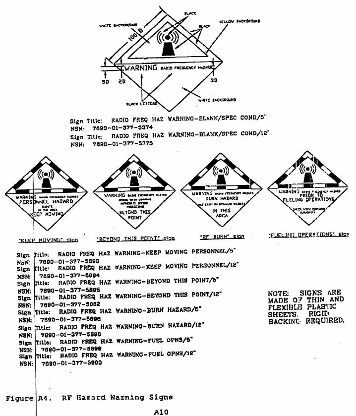
been recommended by the Navy at Camp Smith:
• Post a "KEEP MOVING" RF warning sign at the base of theantenna poles.
• Advise maintenance personnel to secure the transmitter when work isperformed on the antenna or RF cables, or if any other work will bedone within 3 feet of the antenna.
5. Similar EMR hazards analyses have not been conducted at this time at the other Navy locations
where the operational UHF SATCOM Base Station equipment will be installed (i.e., Norfolk,
Virginia; Naples, Italy; and Guam - see Figure 2.2). Similar transceivers will be installed at the
other locations, therefore, similar EMR performance standards regarding separation distances
shall apply at these locations. In accordance with USAF and Navy procedures, prior to the
installation of EMR emitting equipment, such as the AN/WSC-3 transceivers for the CSEL
program, the Navy conducts site specific EMR hazards analyses to assure that PEL standards
are not exceeded. Therefore, prior to the installation of the AN/WSC-3 transceivers at the
operational UHF SATCOM Base Stations to be located at Norfolk, Virginia; Naples, Italy; and
Guam the Navy shall conduct site specific EMR hazards analyses. The Navy shall provide the
results of these EMR hazards analyses to the USAF.
4-6
4.1.2.4 EMR Hazards to Wildlife
1. Similar to EMR hazards to humans, wildlife, particularly birds, may potentially be affected by
RF radiation through the heating of tissue. For RF radiation to affect birds, the bird must stay
within the RF “beam” long enough for tissue heating to occur. Once the bird flies out of the
RF “beam” the exposure to RF radiation ends, and the potential for tissue heating ceases.
2. As noted in the Navy EMR analysis for Camp Smith (see Appendix E), the CSEL program’s
AN/WSC-3 transceivers at the UHF SATCOM Base Stations emits low levels of RF
radiation. In addition, a bird in flight would be within the RF “beam” for only a very short
period of time (i.e., seconds). Therefore, birds would not be affected by the tissue heating
property of RF radiation and would not be affected by the CSEL program.
4.1.3 NO ACTION ALTERNATIVE
Under the No Action Alternative, the CSEL program would not undergo Developmental
Testing or Operational Assessment, and system would not be deployed. While the
RF radiation issues associated with the UHF SATCOM Base Stations would not occur under
the No Action Alternative, these impacts are not significant.
4.2 OTHER POTENTIAL ENVIRONMENTAL ISSUES
1. With the exception of the potential environmental consequences associated with the
uncontrolled venting of the LiSO2 battery pack and the EMR from the CSEL UHF SATCOM
Base Station transceivers, the testing, production, deployment, operation, maintenance, and
disposal of the CSEL hardware and infrastructure on a worldwide basis does not have the
potential to result in environmental consequences.
2. The production of the CSEL hand-held radios and support equipment will not result in any
environmental impact as the production of the system components will take place in existing
contractor facilities designed and permitted for the fabrication of electronic hardware and the
various supporting components. There are various contractors and sub-contractors involved in
the development, manufacturing and integration processes for the CSEL program, with the
prime contractor being Boeing.
4-7
3. The chassis of the CSEL hand-held radio is manufacture from an magnesium alloy. As
Del Mar Casting is an existing facilities designed and permitted for the manufacture of metal
components, including manufacturing products using magnesium alloys, the manufacturing of
the CSEL hand-held radio magnesium alloy chassis is considered to be an ongoing, routine
process that does not require additional environmental analysis as part of the CSEL program.

SECTION 5.0
REGULATORY REVIEW AND PERMIT REQUIREMENTS
5-1
5.0 REGULATORY REVIEW AND PERMIT REQUIREMENTS
5.1 INTRODUCTION
1. As discussed in Chapter 3.0, the Developmental Testing, and Operational Assessment and
Operational Testing of the CSEL system will be conducted at existing DoD and government
contractor facilities which are permitting for performing this type of function, and whose
ongoing missions including the testing and analysis of electronic equipment and systems.
Therefore, the testing and assessment of the CSEL system is considered to be part of the
baseline environmental conditions at the facility and no additional regulatory review or permits
are required.
2. Similarly, the production of CSEL system components (i.e., hand-held radios and support
equipment) will take place in existing contractor facilities designed and permitted for the
fabrication of electronic hardware. Therefore, the production of the CSEL components is
considered to be part of the baseline environmental conditions at the facilities and no additional
regulatory review or permits are required.
3. The deployment, operation, maintenance and disposal of the CSEL system worldwide is
considered to be part of the continuing improvement and evaluation of DoD electronic
systems. With the exception of EMR PELs established by AFOSH standard 48-9 and EMR
separation standards established by MIL-STD-46ID RS103, these are no additional specific
regulatory review or permits required.

SECTION 6.0
PERSONS AND ORGANIZATIONS CONSULTED ORTHAT PROVIDED INFORMATION
6-1
6.0 PERSONS AND ORGANIZATIONS CONSULTEDOR THAT PROVIDE INFORMATION
The following individuals or organizations were consulted or provided information during
preparation of this EA:
• U.S. Air Force- Crotchett, Lt. Col. Denton (SMC/AXZ)- Hashad, Adel (SMC/AXFV)- Hickel, Capt. Brent (SMC/AXEW)- Johnson, Donald (SMC/CZJ - ARINC)- Kasper, John (The Aerospace Corporation)- McGhin, Maj. Robert (AFOTEC/EM)- Namoos, Capt. Omar (SMC/CZJ)- Tshudy, Maj. Thomas (SMC/JA)

SECTION 7.0
REFERENCES
7-1
7.0 REFERENCES
IEEE, 1992. Institute of Electrical and Electronics Engineers, IEEE Standard for Safety Levels withRespect to Human Exposure to Radio Frequency Electromagnetic Fields, 3 kHz to 300 GHz, IEEEC95.1-1991, April 27, 1992.
Johnson, Donald. SMC/CZJ (ARINC). Telephone and Fax Communications. May to July 1997.
U.S. Air Force. Air Force Occupational Safety and Health Standard 48-9.
U.S. Air Force. Request for Environmental Impact Analysis (AF Form 813) - Woodland Cougar1997: Personnel Recovery Exercise. April 21, 1997.
U.S. Army. United States Army Center at Fort Huachuca. Environmental Assessment - MilitaryTraining and Communications - Electronic Testing at Fort Huachuca. January 12, 1993.
U.S. Army. U.S. Army Communications - Electronics Command. Environmental Impact AnalysisWorksheet - CSEL Hand-Held Radio. December 3, 1996.
U.S. Navy. Appendix A: Electronic Radiation (EMR) Hazards and ElectromagneticCompatibility (EMC) Study - CSEL UHF Satellite Communications Base Station at Camp H.M.Smith, Hawaii. March 14, 1997.

APPENDIX A
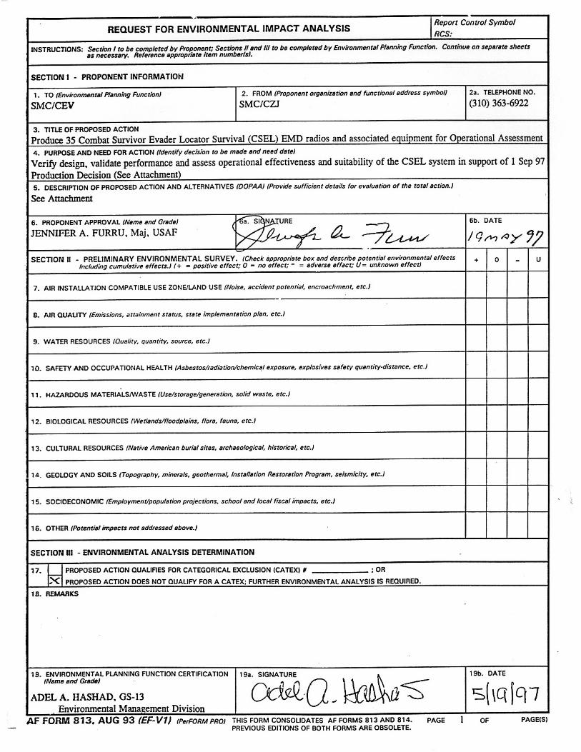
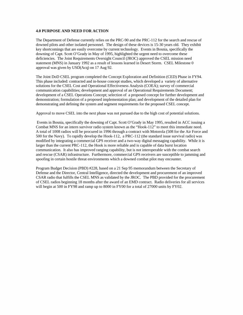
4.0 PURPOSE AND NEED FOR ACTION The Department of Defense currently relies on the PRC-90 and the PRC-112 for the search and rescue of downed pilots and other isolated personnel. The design of these devices is 15-30 years old. They exhibit key shortcomings that are easily overcome by current technology. Events in Bosnia, specifically the downing of Capt. Scott O’Grady in May of 1995, highlighted the urgent need to overcome these deficiencies. The Joint Requirements Oversight Council (JROC) approved the CSEL mission need statement (MNS) in January 1992 as a result of lessons learned in Desert Storm. CSEL Milestone 0 approval was given by USD(Acq) on 17 Aug 92. The Joint DoD CSEL program completed the Concept Exploration and Definition (CED) Phase in FY94. This phase included: contracted and in-house concept studies, which developed a variety of alternative solutions for the CSEL Cost and Operational Effectiveness Analysis (COEA); survey of commercial communication capabilities; development and approval of an Operational Requirements Document; development of a CSEL Operations Concept; selection of a proposed concept for further development and demonstration; formulation of a proposed implementation plan; and development of the detailed plan for demonstrating and defining the system and segment requirements for the proposed CSEL concept. Approval to move CSEL into the next phase was not pursued due to the high cost of potential solutions. Events in Bosnia, specifically the downing of Capt. Scott O’Grady in May 1995, resulted in ACC issuing a Combat MNS for an intern survivor radio system known as the “Hook-112” to meet this immediate need. A total of 1008 radios will be procured in 1996 through a contract with Motorola (508 for the Air Force and 500 for the Navy). To rapidly develop the Hook-112, a PRC-112 (the standard issue survival radio) was modified by integrating a commercial GPS receiver and a two-way digital messaging capability. While it is larger than the current PRC-112, the Hook is more reliable and is capable of data burst location communication. It also has improved ranging capability, but is not interoperable with the combat search and rescue (CSAR) infrastructure. Furthermore, commercial GPS receivers are susceptible to jamming and spoofing in certain hostile threat environments which a downed combat pilot may encounter. Program Budget Decision (PBD) #228, based on a 21 Sep 95 memorandum between the Secretary of Defense and the Director, Central Intelligence, directed the development and procurement of an improved CSAR radio that fulfills the CSEL MNS as validated by the JROC. The PBD provided for the procurement of CSEL radios beginning 18 months after the award of an EMD contract. Radio deliveries for all services will begin at 500 in FY98 and ramp up to 8000 in FY00 for a total of 27000 units by FY02.
In order to ensure the operational suitability and effectiveness of the CSEL system before deployment in FY98, Developmental Testing and an Operational Assessment will be conducted between 1 July and 30 August 97 using 35 production representative EMD radios. The results of these tests will be used to fine-tune the system design and to support the production decision in September 97. 5.0 DESCRIPTION OF PROPOSED ACTION AND ALTERNATIVES (DOPAA) 5.1 INTRODUCTION This DOPAA will provide an accurate description of the CSEL system and a description of the proposed action namely the design, development and fabrication of thirty-five EMD radios, two UHF SATCOM Base Stations, six CSEL Handheld Radio Loader/Adapters, four Joint Search and Rescue Centers and the developmental tests and Operational Assessment to be conducted on the system. The DOPAA concludes with a brief analysis of several alternatives to the proposed action. 5.2 SYSTEM DESCRIPTION The Combat Survivor/Evader Locator (CSEL) System provides global over-the-horizon (OTH) data communications, line of sight (LOS) voice communications, and precise GPS positioning capabilities for Department of Defense (DoD) warfighters when they are confronted with survival and/or evasion scenarios in peacetime and conflict situations. It is composed of three segments: User Equipment, Over-the-Horizon (OTH) Relay, and Ground. Figure 1 shows the CSEL System architecture. 5.2.1 OTH Relay Segment The OTH Relay segment includes two Satellite Communication (SATCOM) systems to provide total Earth coverage. These two systems are the Ultra High Frequency (UHF) SATCOM (UHFSATCOM) and Search & Rescue Satellite Assisted Tracking (SARSAT). These OTH systems operate in the UHF or near-UHF frequency band of 225 to 406.025 MHz, and jointly provide continuous world-wide (70N to 70S latitude) OTH converage. 5.2.1.1 UHFSATCOM The UHFSATCOM relay mode supports 2-way messaging/geolocation between the survivor/evader (S/E) with hand held radio (HHR) and a UHFSATCOM Base Station (UBS) using a UHFSATCOM 5 kHz channel. In order to avoid collisions between multiple S/Es that might send messages simultaneously, CSEL employs a time division multiple access (TDMA) format. This format allows CSEL to share the UHFSATCOM channel with other users of this asset. This channel-sharing scheme is
compatible with the DoD-mandated Demand Assigned Multiple Access (DAMA) protocols that govern the use of UHFSATCOM channels and is referred to as the DAMA-C format. The DAMA-C format utilizes the first 0.699 seconds of the full 1.387 second DAMA frame. CSEL schedules users requesting access by assigning each user a slot in which only that user can transmit. Each scheduled slot is further divided into three segments: one in which unscheduled HHR transmissions can be sent (refer to next paragraph), one for the UBS to transmit to the HHR assigned that slot, and one in which the S/E scheduled in that slot transmits. The scheduling of this TDMA format is controlled by the UBS which requires input from a DAMA controller (Further described below). Once a S/E has requested access by sending an unscheduled transmission, the S/E is assigned a sub-frame in which all further scheduled transmissions would be made. An internal clock in the HHR ensures that it stays synchronized to DAMA time via a mode message that is continuously broadcast by the UBS. The DAMA-C protocol accommodates approximately 100 users simultaneously in each UHFSATCOM area of coverage. Each user is guaranteed one scheduled slot per half-hour. 5.2.1.1.1 The UHFSATCOM Base Station (UBS) UBS equipment, illustrated in Figure 2, is installed in four geographic locations throughout the world. UBSs provide connectivity to UHFSATCOM satellites located at approximately 100° West, 23° West, 72° East, and 172° East Longitude. The four UBSs will be collocated at existing Naval Computer and Telecommunications Area Master Station (NCTAMS) facilities. They receive and transmit CSEL encrypted messages that are relayed to/from users via the UHFSATCOM satellites. The CSEL UBS equipment consists of a UHFSATCOM transceiver (AN/WSC-3 (v 9)), a rack-mounted Pentium computer with custom UHFSATCOM signal processing software, routing database and messaging software that delivers messages back and forth to the appropriate Joint Search and Rescue Center (JSRC). The computer performs the UHFSATCOM command and control functions and executes the messaging software. The encrypted CSEL data is transmitted at 300 bps, appended with a cyclic redundancy coding (CRC) tail for error detection, and BPSK modulated. The UBS hardware and software is configured in two duplicated racks with one acting as a primary and the other as a hot backup to provide redundancy. CSEL communications data is encrypted to provide date security with a unique primary and backup encryption key provided to each user.
5.2.1.2 SARSAT The SARSAT mode operates over the international SARSAT/COSPAS Low Earth Orbit (LEO) satellite system and is intended for emergency coverage above 70° latitudes where UHFSATCOM and National Asset coverage may be lacking. Unencrypted CSEL transmissions via SARSAT are received at the U.S. Mission Control Center, processed, and forwarded to a CONUS UBS for routing to the JSRC. Either data or Doppler location modes are supported on SARSAT. There are no timing constraints on the SARSAT transmissions at 406.025 MHz. 5.2.1.3 Commercial System Growth The CSEL System architecture is designed for future growth to include a commercial satellite link, when available. Commercial satellite communication services allow CSEL to become independent of the heavily-subscribed UHFSATCOM satellites. The system does not currently accommodate commercial satellite services. 5.2.2 The Ground Segment The CSEL ground segment is composed of CSEL data receiving, display, and dissemination capabilities in the JSRCs. The existing/evolving Defense Information System Network (DISN) interconnects the four UBSs with the world-wide network of JSRCs. The JSRC is the hub of the CSEL system from a command and control perspective, performing data distribution and information flow to search and rescue personnel. The JSRC display provides the capability to read incoming messages received from the HHR. The incoming message will provide the S/E ID authentication, location, status, time of message transmission, time of last GPS fix, time of message receipt, data type, frequency, and the OTH asset in use to the JSRC operator. CSEL software for the JSRCs will be hosted on SUN, HP, or PC workstations running the Defense Information Infrastructure Common Operating Environment (DII COE). 5.2.3 User Equipment Segment The User Equipment segment consists of HHRs provided to Department of Defense (DoD) personnel who may be faced with a survival or evasion situation, CSEL Planning Computers (CPCs) to load mission specific information into the HHR prior to a mission, and HHR Loader/Adapters (HLAs) that serve as an interface between the CPC and the HHR. 5.2.3.1 The Hand Held Receiver (HHR) The 28 ounce HHR chassis includes a P(Y)-code GPS receiver, a VHF/UHF LOS 2-way unencrypted voice transceiver, VHF/UHF rescue beacons, a 2-way secure OTH data transceiver and a SARSAT compatible rescue beacon. The lithium sulfur dioxide (LiSO2) battery pack provides longer battery life over a wider temperature range than conventional alkaline batteries. The HHR is a software reprogrammable design that meets ease of use requirements. Messages from the HHR is a software reprogrammable design that meets ease of use requirements. Messages from the HHR contain a precise Y-Code GPS position, S/E situation information, authentication of the user’s identity, and can contain freeform text information to support user authentication prior to initiating the rescue operation and/or provide commands/information to the S/E from
a JSRC to assist in evasion. Figure 3 illustrates the modular construction of the HHR. The chassis assembly houses the following plug-in modules: (1) The controller module serves as the central control element of the HHR, interfacing with the user keypad, switches, display and other subsystem modules. Additionally, the module provides DC power regulation/control, data processing, and data encryption. (2) The single integrated VHF/UHF transceiver module performs all LOS voice and standard OTH communications functions. (3) The L1/L2 GPS receiver module provides PPS location and navigation capability to the S/E. The receiver uses an all-in-view search routine for maximum precision. It is also capable of Direct-Y acquisition of the Y-code. The highly modular HHR design allows for inexpensive upgrades. In such upgrade might be a replacement module for the VHF/UHF card that would support use of commercial satellite communications systems. 5.2.3.2 HHR Support Equipment Support equipment necessary to operate the CSEL HHR is minimal. The CPC and HLA, shown in Figure 4, provide the data interface for loading all mission data. These include UHF/VHF operational frequencies, communication cryptographic keys, escape/evasion routes, safe zone coordinates, canned messages, precise time, GPS almanac/ephemerides, GPS cryptograghic keys, and other pertinent information. 5.2.3.3 HHR Main and Back-Up Battery The CSEL HHR main battery pack contains four “half-D” LiSO2 cells to provide operations at – 40 °C. The battery pack is designed with personnel and environmental safety concerns keenly in mind. The pack includes a logic circuit that prevents rapid discharge of the battery cells (which has been shown to cause violent venting). This logic circuit also includes the Controlled Discharge Device which ensures safe storage, transport and disposal of expended batteries. In addition, the case has strategically-placed “pressure points” that are designed to guide hot toxic fumes away from the operator in the unlikely event of a venting incident. LiSO2 chemistry is expected to be the most significant environmental and safety concern related to CSEL. For this reason, a major part of the proposed developmental testing is focused on certifying the battery for use by all three services – Army, Navy and Air Force. The CSEL HHR also contains a back-up coin-cell battery that is used to keep parts of the volatile memory alive when the HHR battery is removed. The battery used for this back-up function is a
CR1620 battery with considerably less environmental obstacles. It is a commercially available coin-cell battery that can be handled like any other commercially-available lithium battery. 5.3 DESCRIPTION OF THE PROPOSED ACTION 5.3.1 Production of 35 EMD Radios and Support Equipment In order to support testing, the contractor will design, develop and fabricate 30 EMD HHRs and 6 HLAs for delivery to the government. 5 additional HHRs will be built and used by the contractor for their own testing. In addition to HHRs and HLAs, the contractor will deliver to the government four Sun Ultra workstations loaded with the CSEL JSRC software, CPC soft ware to be loaded on GFE Pentium computers and four racks of UBS equipment. Each rack includes the following major components: AN-WSC3 (v9) SATCOM radio Pentium Computer with peripherals Power supply module CSEL-unique signal processing cards GPs receiver card Reference HHR (one per two UBS racks) The production of the equipment should pose no significant environmental concerns. BOEING, North American (BNA) is the prime contractor and there are several sub-contactors involved in the development, manufacturing and integration processes: Final assembly of HHR BNA, El Paso, TX Manufacture of HHR VHF/UHF Module Racal Instruments, Rockville, MD Manufacture of HHR Controller Module BNA, El Paso, TX Manufacture of HHR GPS Module Rockwell Collins, Coralville, IA Design of HHR GPS Module Rockwell Collins, Cedar Rapids, IA Manufacture of HHR Magnesium alloy chassis Del Mar Casting, Gardena, CA Final assembly of HHR Battery Pack Blue Star, Inc., Surey, BC Manufacture of LiSO2 cells Blue Star, Inc., Surey, BC Manufacture of plastic battery cases Blue Star, Inc., Surey, BC Final assembly of UBS BNA, Anaheim, Ca Manufacture of UBS signal processing H/W BNA, El Paso, TX Development of UBS source code BNA, Anaheim, Ca Final assembly of JSRC BNA, Anaheim, Ca Development of JSRC source code BNA, Anaheim, Ca Final assembly of HLAs BNA, El Paso, TX Development of CPC source code BNA, Anaheim, Ca Other vendors are involved as parts suppliers to the vendors listed. They are omitted from this analysis.
There are two areas where further analysis on environmental impacts might be appropriate: manufacture of the Magnesium alloy chassis, and the manufacture, handling, delivery and disposal of the LiSO2 battery cells. Attachment A (provided at a later date) is a System Safety Analysis done by Del Mar Casting, the company that makes the chassis, demonstrating that the company implements policies and procedures to mitigate the minor risks of working with Magnesium alloys. A similar analysis has been done by Blue Star, and is included in Attachment B (provided at a later date). Other environmental issues that may arise from chemicals and procedures employed in the manufacturing process have been analyzed by the manufacturing contractor, Boeing North American, El Paso facility. A description of their industry-standard safety guideline is included as Appendix C (provided at a later date). 5.3.2 Developmental Testing Developmental Testing (DT) will be performed to validate system performance at specification requirements. DT is performed by trained test personnel from BNA. Combined Testing (CT) is performed at several government test centers, including: EPG, Holloman AFB, and NSWC to supplement DT and provide initial operational environment performance data. In addition, Acceptance Testing, and Qualification Testing will be performed by BNA, El Paso prior to the delivery of development and production radios to the government. 5.3.2.1 Army Electronic Proving Grounds (EPG), Ft Huachuca, AZ EPG will perform testing on the HHR radiated transmissions to test radiated power, link margin and bit error rates (BER). Software in the HHR, CPC, JSRC and UBS will be tested for ease of use. Regression analysis will also be run on the software. In addition, the Joint Interoperability Test Center (JITC), a tenant of EPG, will certify frequency interoperability of CSEL. 5.3.2.2 746th Test Squadron, Holloman AFB, NM The 746th is the Responsible Test Organization (RTO) for all CSEL DT. In addition to administering the integrated (government/contractor) DT plan, the 746th will conduct all GPS-related testing and acceleration survivability testing. 5.3.2.3 Navy Systems Warfare Center (NSWC), Indianapolis, IN The NSWC is in charge of safety certification testing for the Lithium battery. They will perform exhaustive tests to determine the battery’s ability to withstand extreme conditions in the hands of operators. This certification program will include tri-service requirements for battery safety. 5.3.2.4 Boeing North American (BNA) and associated Sub-Contractors Testing at the component, module, and system level is on-going at the contractor sites throughout the development process. The Government is invited to witness these tests in order to minimize redundancy in the test program. Contractor DT maximizes the use of brassboards, workbench prototypes, analysis and simulation. In addition to DT, the contractors are involved in formal Qualification Testing and Acceptance Testing to show compliance with end item specification parameters.
5.3.3 Operational Assessment (OA) The OA will be conducted by the Air Force Test & Evaluation Center (AFOTEC), Kirtland AFB, NM. As the responsibility agency for Operational Test (OT) of the CSEL system, AFOTEC will coordinate resources, tri-service participation in the OA, locations of test events, test objectives and pass/fail criteria. As discussed earlier, one of the prime directives in OT is to conduct an independent assessment of the system that represents the perspective of the warfighter. Consequently, all testing is conducted with “operators” instead of engineers, contractors and program managers. These individuals may or may not have been trained in the proper handling and disposal of hazardous materials warnings, this lack of training is not expected to have an impact on the safety of the individuals involved with testing. 5.3.3.1 Operational Scenarios The OA will consist of three scenarios that will be executed multiple times to get an accurate characterization of the system’s effectiveness and operational suitability. CSEL test scenarios will be based on actual mission conduct. Variations in the mission scenarios for differing environmental conditions (such as darkness, foliage, terrain, precipitation, low temperatures, water, etc.) will be accounted for in the respective detailed test procedures. The CSAR mission scenarios will include ground team extraction, SAR Task Force (SARTF) extraction, and opportunity SAR scenarios. These three scenarios will be the basis for all test events conducted during dedicated operational testing. Testing events will use operational personnel in Alaska, Washington and Hawaii. No dedicated range support is required. The three scenarios will be used at each location. These scenarios were specifically designed to represent the operating environment that is envisioned for the system. They are briefly described below: Scenario 1:a. Scenario 1: Ground Team Extraction Scenario Description. This CSAR mission is to extract aircrew members shot down over hostile territory. CSAR activity will be conducted behind the Forward Edge of the Battle Area (FEBA) in a simulated high threat environment. Direct threats to CSAR force elements include Surface-to-Air Missiles (SAM0, anti-aircraft artillery (AAA), and small arms fire from enemy troop concentrations. Collateral threats include communications radio monitoring and direction finding to locate communications emissions. This threat environment prevents standard helicopter extraction. For AFOTEC’s evaluation, a Combat Rescue Extraction Training Exercise (CRETE) will be conducted. The simulated survivors will initiate the CRETE by transmitting a “notification” message from the HHR through CSEL OTH communications assets to the UBS. The UBS routes the S/E information to the appropriate JSRC. The JSRC identifies and locates the S/Es and relays the S/E ID, status and location information to the local Rescue Control Center (RCC); this coordination takes place outside of the CSEL system. The JSRC transmits an authentication query back through the UBS back to the S/E’s HHR. The S/E responds with the requested information back over the path described above. The JSRC then directs the S/Es to link up with each other at a designated location. The local RCC dispatches a four-man parajumper (PJ) team who are airdropped by a
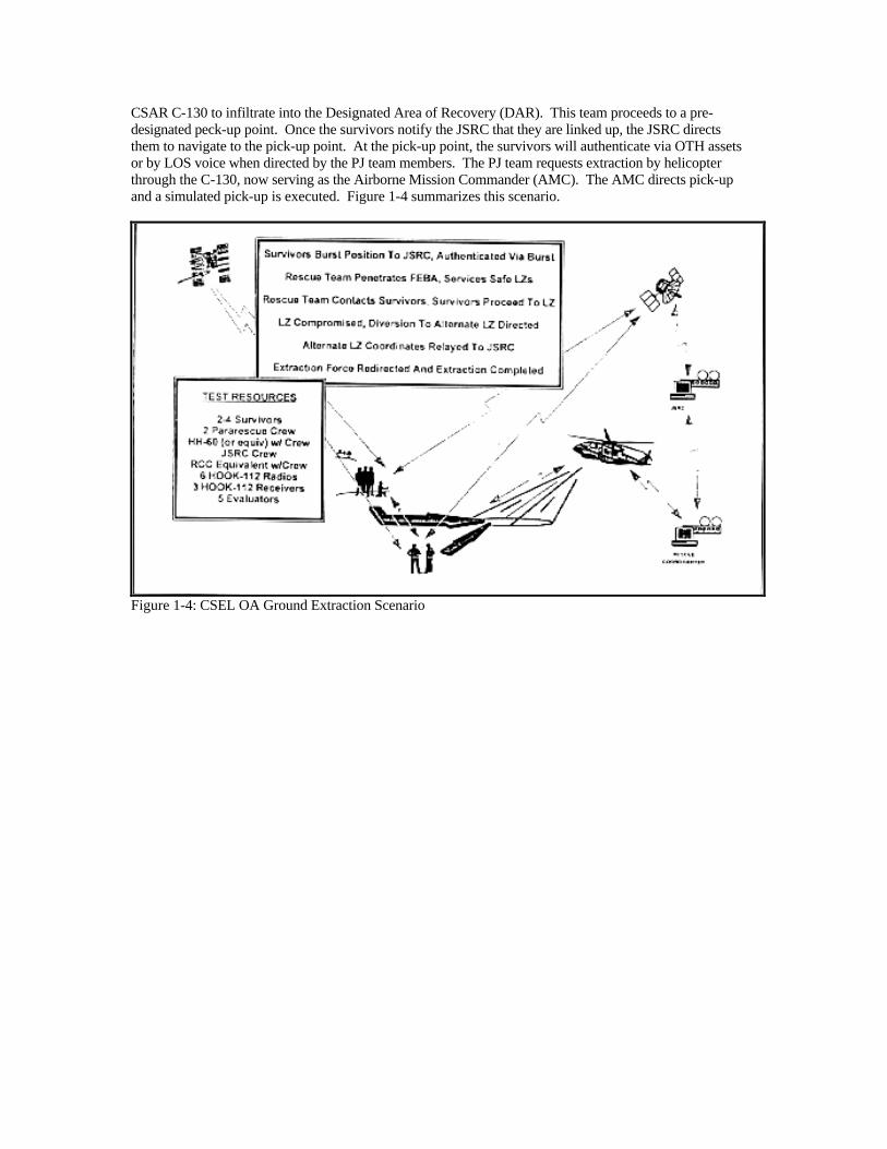
CSAR C-130 to infiltrate into the Designated Area of Recovery (DAR). This team proceeds to a pre-designated peck-up point. Once the survivors notify the JSRC that they are linked up, the JSRC directs them to navigate to the pick-up point. At the pick-up point, the survivors will authenticate via OTH assets or by LOS voice when directed by the PJ team members. The PJ team requests extraction by helicopter through the C-130, now serving as the Airborne Mission Commander (AMC). The AMC directs pick-up and a simulated pick-up is executed. Figure 1-4 summarizes this scenario.
Figure 1-4: CSEL OA Ground Extraction Scenario
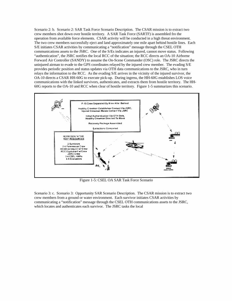
Scenario 2: b. Scenario 2: SAR Task Force Scenario Description. The CSAR mission is to extract two crew members shot down over hostile territory. A SAR Task Force (SARTF) is assembled fro the operation from available force elements. CSAR activity will be conducted in a high threat environment. The two crew members successfully eject and land approximately one mile apart behind hostile lines. Each S/E initiates CSAR activities by communicating a “notification” message through the CSEL OTH communications assets to the JSRC. One of the S/Es indicates an injured, cannot move status. Following “authentication”, the JSRC notifies the local RCC of the situation; the RCC directs an OA-10 Airborne Forward Air Controller (SANDY) to assume the On-Scene Commander (OSC) role. The JSRC directs the uninjured airman to evade to the GPS coordinates relayed by the injured crew member. The evading S/E provides periodic position and status updates via OTH data communications to the JSRC, who in turn relays the information to the RCC. As the evading S/E arrives in the vicinity of the injured survivor, the OA-10 directs a CSAR HH-60G to execute pick-up. During ingress, the HH-60G establishes LOS voice communications with the linked survivors, authenticates, and extracts them from hostile territory. The HH-60G reports to the OA-10 and RCC when clear of hostile territory. Figure 1-5 summarizes this scenario.
Figure 1-5: CSEL OA SAR Task Force Scenario
Scenario 3: c. Scenario 3: Opportunity SAR Scenario Description. The CSAR mission is to extract two crew members from a ground or water environment. Each survivor initiates CSAR activities by communicating a “notification” message through the CSEL OTH communications assets to the JSRC, which locates and authenticates each survivor. The JSRC tasks the local
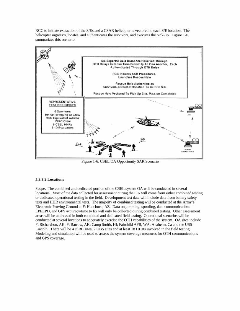
RCC to initiate extraction of the S/Es and a CSAR helicopter is vectored to each S/E location. The helicopter ingress’s, locates, and authenticates the survivors, and executes the pick-up. Figure 1-6 summarizes this scenario.
Figure 1-6: CSEL OA Opportunity SAR Scenario
5.3.3.2 Locations Scope. The combined and dedicated portion of the CSEL system OA will be conducted in several locations. Most of the data collected for assessment during the OA will come from either combined testing or dedicated operational testing in the field. Development test data will include data from battery safety tests and HHR environmental tests. The majority of combined testing will be conducted at the Army’s Electronic Proving Ground at Ft Huachuca, AZ. Data on jamming, spoofing, data communications LPI/LPD, and GPS accuracy/time to fix will only be collected during combined testing. Other assessment areas will be addressed in both combined and dedicated field testing. Operational scenarios will be conducted at several locations to adequately exercise the OTH capabilities of the system. OA sites include Ft Richardson, AK; Pt Barrow, AK; Camp Smith, HI; Fairchild AFB, WA; Anaheim, Ca and the USS Lincoln. There will be 4 JSRC sites, 2 UBS sites and at least 18 HHRs involved in the field testing. Modeling and simulation will be used to assess the system coverage measures for OTH communications and GPS coverage.
Operators will be located at various sites around the United States, including Hawaii and Alaska. They will be comprised of Rescue Center operators, UBS maintainer/operators, HHR users (mock survivors), and CPC operators. JSRC operators will be located in four locations: Ft. Belvoir, VA; Ft Richardson, AK; Pacific Rescue Coordination Center (PRCC), Honolulu, HI; and aboard the USS Tarawa (anticipated to be off the coast of San Diego during OA). Two UBS racks will be installed for the OA.. One will be at Camp Smith, HI and one will be at EPG, Ft Huachuca, AZ. A third UBS will be installed at the BNA plant in Anaheim, CA. This UBS will be manned by BNA engineers. Finally, survivors and CPC operators will be dispersed over multiple locations, including Kirtland AFB, NM, Nellis AFB, NV, Ft Richardson, AK, Camp Smith, HI, Ft Huachuca, AZ, Pt Barrow, AK, and Fairchild AFB, WA. 5.4 DESCRIPTION OF ALTERNATIVES TO THE PROPOSED ACTION 5.4.1 Test Battery With Safer Chemistry and Lower Capability Since the LiSO2 battery is one of the few aspects of the CSEL program where an environmental consideration exists, one alternative approach is to find ways to use other (more inert) batteries to the extent possible. The LiSO2 battery is one of the few batteries capable of meeting CSEL’s demanding performance requirements (21 days battery life at 25 deg C and 3 days battery life at – 40 deg C). It may be possible, however, to conduct much of the testing using an alternate battery chemistry. This option has been avoided due to the impact it would have on the schedule, cost and technical performance of the CSEL system. Each battery that is developed for CSEL must be designed and tested, and then certified by government agencies before it can be employed with the sys. This process takes more advanced planning than can be afforded on CSEL’s short schedule. Furthermore, a parallel battery development will have a tremendous impact on the cost of the program (for the same reasons). Finally, it is difficult to find an alternate battery chemistry that provides the peak power required for the HHR to transmit an 8 watt signal that can be heard by a satellite. This pack would prevent the testing of link margins, extreme temperature operation, and other key performance parameters. 5.4.2 “Do Nothing” Alternative This option would result in the termination of the CSEL Program efforts and the loss of all program efforts to date which is an unacceptable solution.
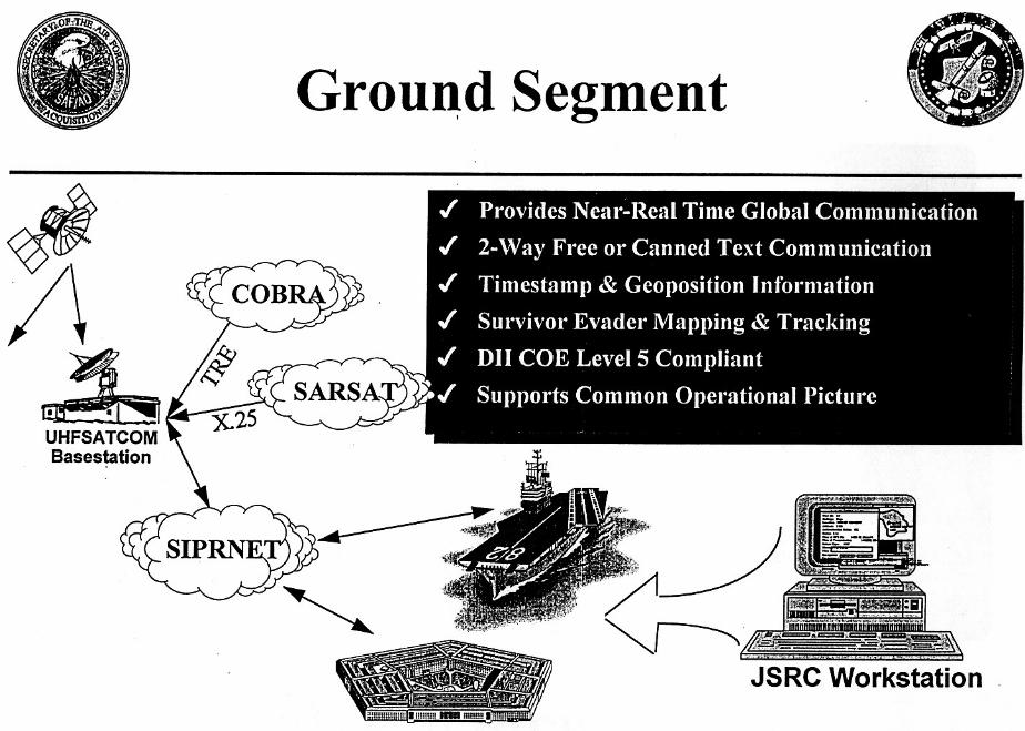
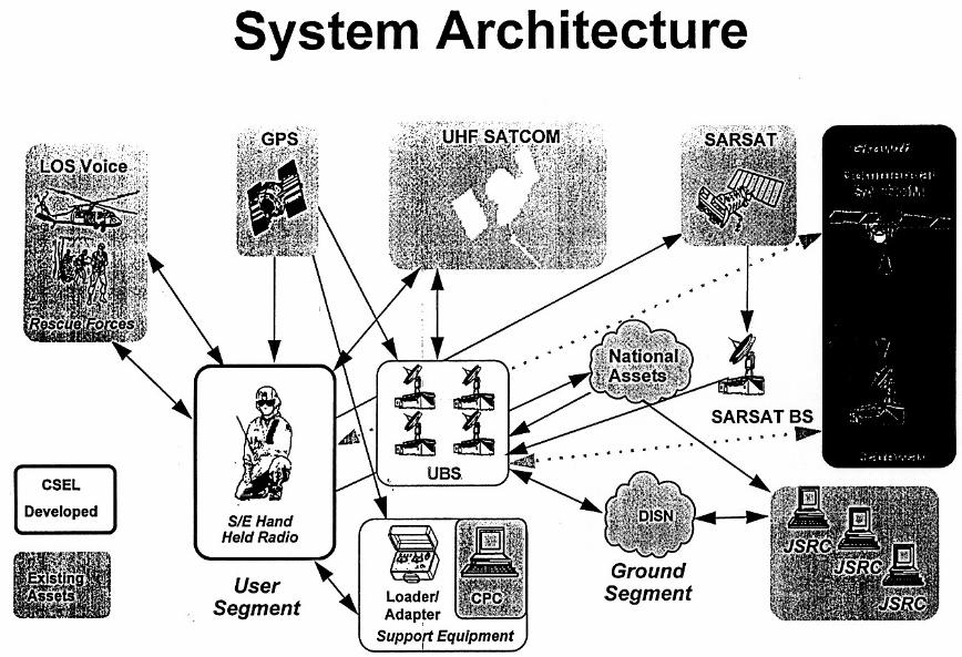
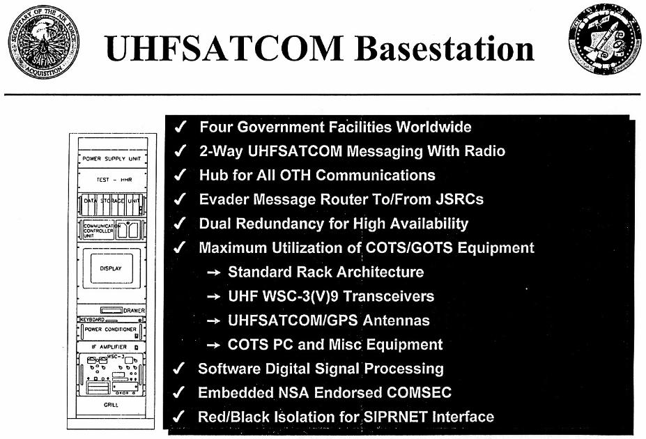
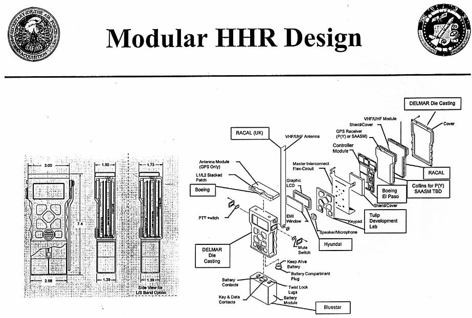
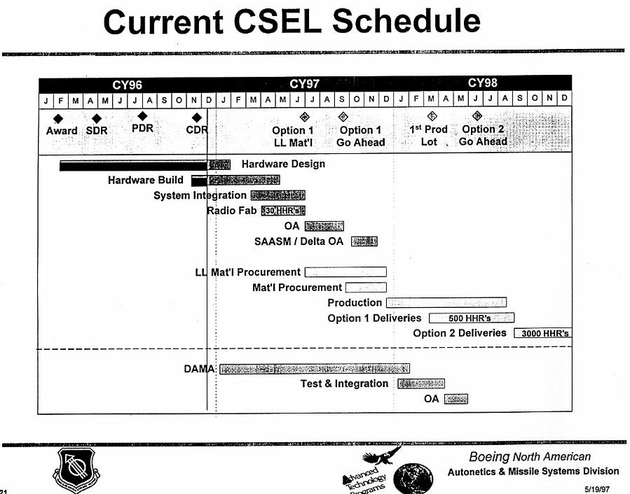
APPENDIX B
AIR FORCE FORM 813 WOODLAND COUGAR 1997 – PERSONNEL RECOVERY EXERCISE
BACKGROUND PAPER
ON
WOODLAND COUGAR ’97 PLANS This paper discusses the current plans for Personnel Recovery (PR) exercise WOODLAND COUGAR ’97
(WC97). Details of the exercise scenario, operation plans, specific exercise events, and participating units
are identified. The paper concludes with a risk assessment of the current WC97 plans and recommended
plans of action to reduce risks associated with this PR exercise.
WC97 Scenario
- Emulates a Korean operational scenario
− Includes current material from Korean theater (CSAR Special Operating Instructions, Concept of
Operations, and Standard Operating Procedures)
− Scenario emulates a higher operations tempo than would be expected in the actual Korean theater
− Active aggression of survivors
− Tactical interrogation of captives
- Low, medium to high threats are scripted, allowing a variety of Personnel Recovery (PR) response
options
Operational Plans
- Operational plans developed from Joint CSAR Doctrine, Joint Pubs 3.50.1-4
- Twenty-four hour operations commencing on 20 Aug 97 through 1200, 27 Aug 97
− Two-twelve hour exercise control shifts oversee three – six hour flying shifts
MSgt Toutillotte/336 TRG/OSX/mkh/16 Apr 97 AFD: mydoc\bkgdWC97
1
- Day and night operations - Active aggression provided by SERE instructors, US Army Rangers
- Electronic threats supported by 336 Range Squadron, MT Home AFB ID
- Tactical interrogations performed by qualified SERE instructors for validations of S-V80-A learning
outcomes
Operational Control
- 336 TRG/CC will be the PR exercise commander
- Joint Exercise Control group (JECG) controls overall events of the exercise and will be supervised by
rated squadron commanders from the 336 TRG
- Aircrew members and Life Support personnel are inserted as “survivors/evaders”
- SERE instructors escort survivors throughout the PR exercise
− Escorts ensure overall safety of survivor
− JECG provides administrative inputs through the escorts, as needed
- Joint Search and Rescue Center manned by trained personnel from PACAF, CENTAF and HQ ACC
Rescue Coordination Centers
- All flight operations controlled by each Wing Operations Center/Special Operations Center
− Planned unconventional air assets include satellite assets and Unmanned Air Vehicles (UAVs)
− Special Forces teams include Navy SEALs and Marine Force Recon
- Participating units, their CSAREX role, and associated aircraft (if applicable) are identified in Appendix 2
AFD: mydoc\bkgdWC97
2
Upcoming milestones
Milestones Date(s)
- Final Planning Conference 28, 29 May 97
-WC97 PR exercise 20 – 27 Aug 97
- After-Action Report due to 336 TRG/CC 1 Oct 97
Risk Assessment of WC97 Events
- Risks associated with PR exercise planning and operations are identified along with an appropriate plan of
action to reduce/negate risk
- Flight Safety and Ground Safety review of all flight/ground operations will be conducted prior to
STARTEX
Summary
- WOODLAND COUGAR ’97 uses a Korean scenario
− Assumes current Korean conditions have degraded to involve NATO forces in low-high threats for
PR operations
− Active aggression and tactical interrogation planned
- Operations
− Uses current PR doctrine as described by Joint Pubs 3.50.1-4
− Controlled by 336 TRG/CC and Joint Exercise Control Group
− PR operations will be controlled by JSRC
- PR Events
− Multiple events create a dynamic PR environment
AFD: mydoc\bkgdWC97
3
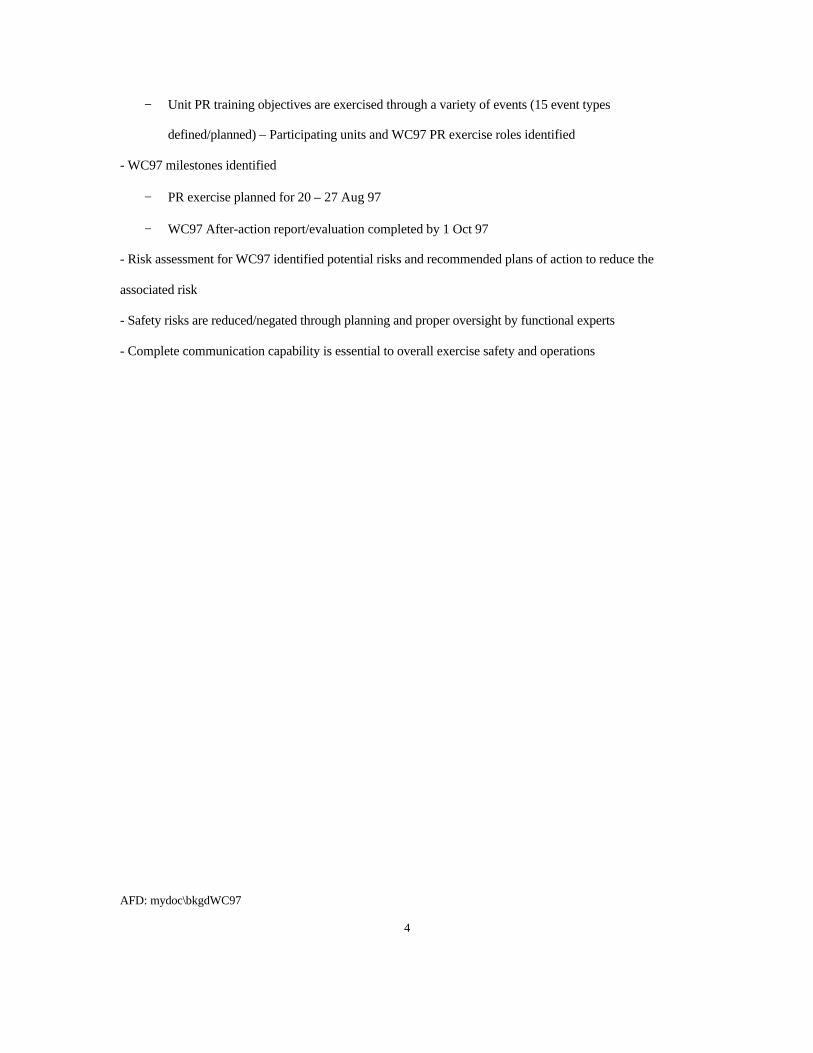
− Unit PR training objectives are exercised through a variety of events (15 event types
defined/planned) – Participating units and WC97 PR exercise roles identified
- WC97 milestones identified
− PR exercise planned for 20 – 27 Aug 97
− WC97 After-action report/evaluation completed by 1 Oct 97
- Risk assessment for WC97 identified potential risks and recommended plans of action to reduce the
associated risk
- Safety risks are reduced/negated through planning and proper oversight by functional experts
- Complete communication capability is essential to overall exercise safety and operations
AFD: mydoc\bkgdWC97
4
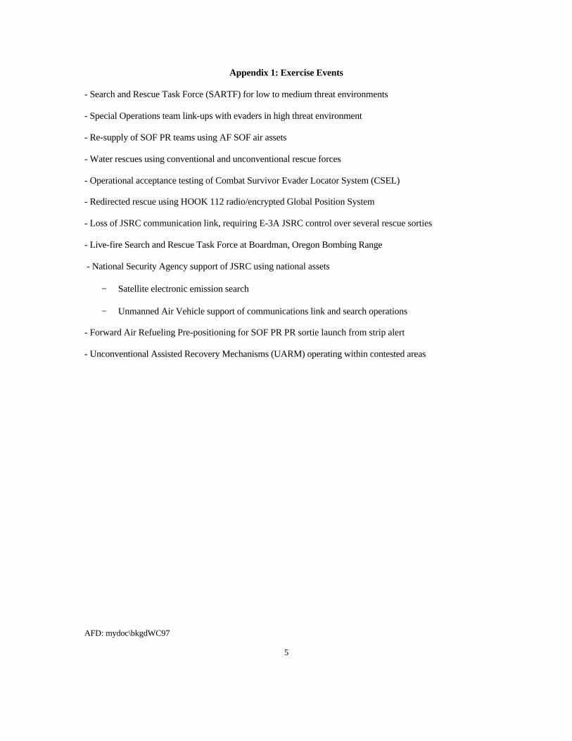
Appendix 1: Exercise Events
- Search and Rescue Task Force (SARTF) for low to medium threat environments
- Special Operations team link-ups with evaders in high threat environment
- Re-supply of SOF PR teams using AF SOF air assets
- Water rescues using conventional and unconventional rescue forces
- Operational acceptance testing of Combat Survivor Evader Locator System (CSEL)
- Redirected rescue using HOOK 112 radio/encrypted Global Position System
- Loss of JSRC communication link, requiring E-3A JSRC control over several rescue sorties
- Live-fire Search and Rescue Task Force at Boardman, Oregon Bombing Range
- National Security Agency support of JSRC using national assets
− Satellite electronic emission search
− Unmanned Air Vehicle support of communications link and search operations
- Forward Air Refueling Pre-positioning for SOF PR PR sortie launch from strip alert
- Unconventional Assisted Recovery Mechanisms (UARM) operating within contested areas
AFD: mydoc\bkgdWC97
5
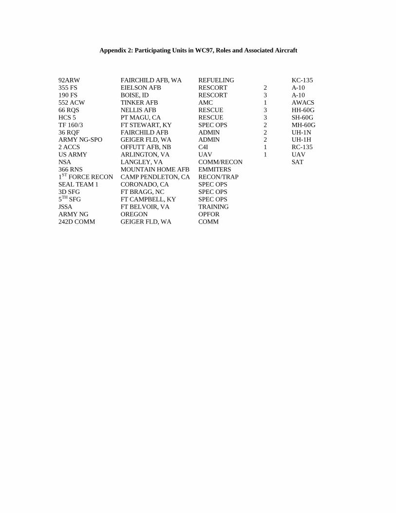
Appendix 2: Participating Units in WC97, Roles and Associated Aircraft
92ARW FAIRCHILD AFB, WA REFUELING KC-135 355 FS EIELSON AFB RESCORT 2 A-10 190 FS BOISE, ID RESCORT 3 A-10 552 ACW TINKER AFB AMC 1 AWACS 66 RQS NELLIS AFB RESCUE 3 HH-60G HCS 5 PT MAGU, CA RESCUE 3 SH-60G TF 160/3 FT STEWART, KY SPEC OPS 2 MH-60G 36 RQF FAIRCHILD AFB ADMIN 2 UH-1N ARMY NG-SPO GEIGER FLD, WA ADMIN 2 UH-1H 2 ACCS OFFUTT AFB, NB C4I 1 RC-135 US ARMY ARLINGTON, VA UAV 1 UAV NSA LANGLEY, VA COMM/RECON SAT 366 RNS MOUNTAIN HOME AFB EMMITERS 1ST FORCE RECON CAMP PENDLETON, CA RECON/TRAP SEAL TEAM 1 CORONADO, CA SPEC OPS 3D SFG FT BRAGG, NC SPEC OPS 5TH SFG FT CAMPBELL, KY SPEC OPS JSSA FT BELVOIR, VA TRAINING ARMY NG OREGON OPFOR 242D COMM GEIGER FLD, WA COMM
APPENDIX C
U.S. ARMY COMMUNICATIONS – ELECTRONICS COMMAND ENVIRONMENTAL IMPACT ANALYSIS WORKSHEET-
OPERATIONAL TESTING OF CSEL SYSTEM
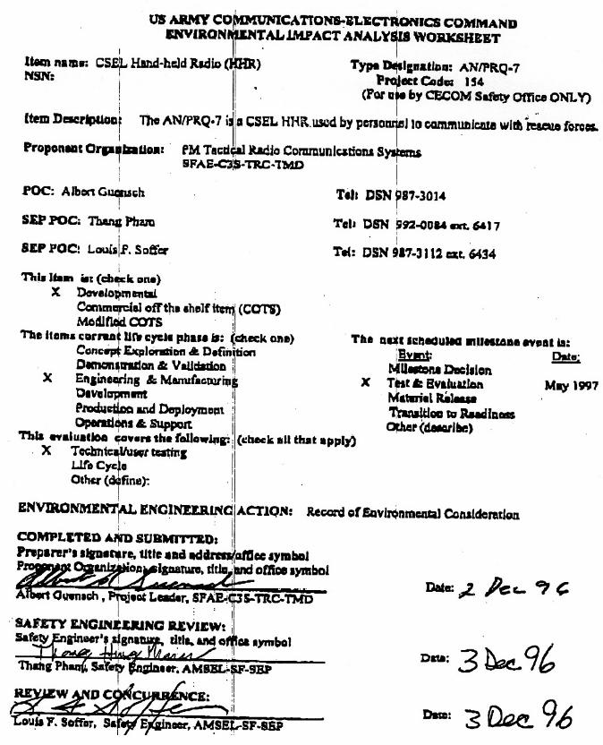
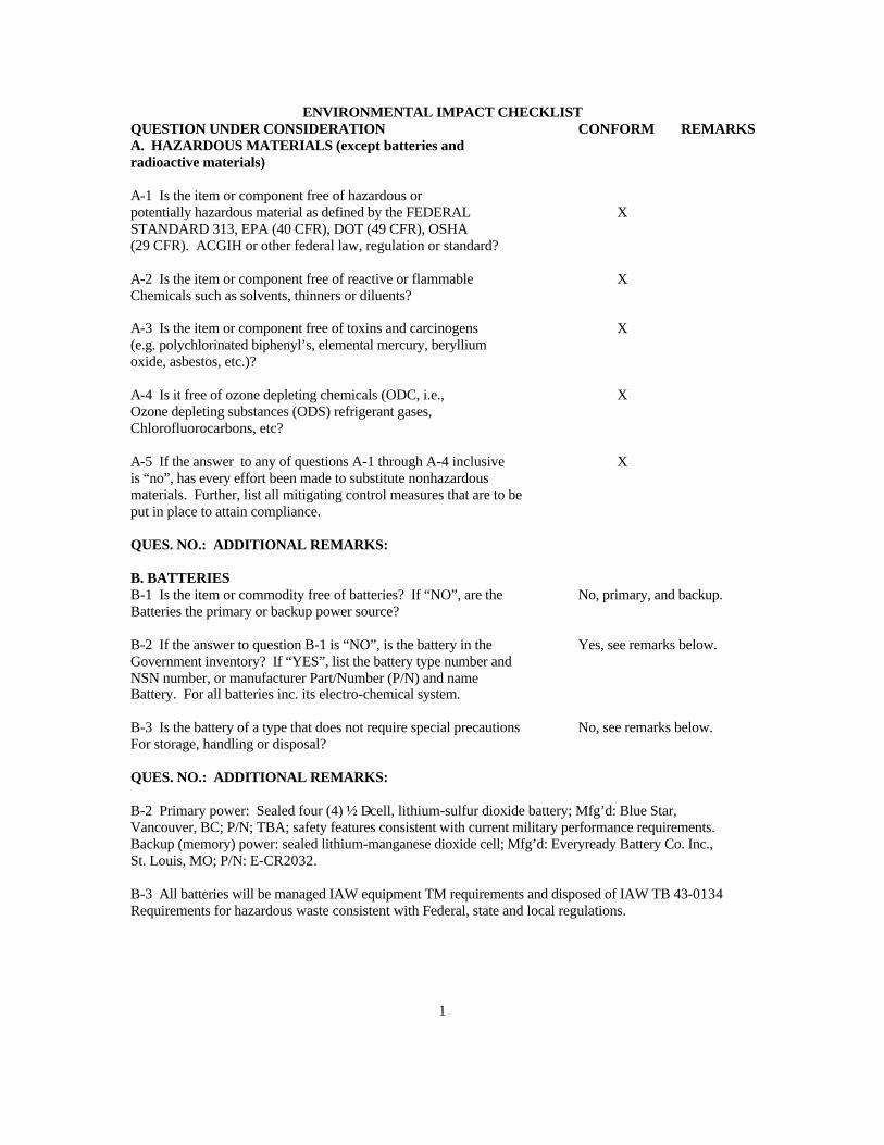
ENVIRONMENTAL IMPACT CHECKLIST QUESTION UNDER CONSIDERATION CONFORM REMARKS A. HAZARDOUS MATERIALS (except batteries and radioactive materials)
A-1 Is the item or component free of hazardous or potentially hazardous material as defined by the FEDERAL STANDARD 313, EPA (40 CFR), DOT (49 CFR), OSHA (29 CFR). ACGIH or other federal law, regulation or standard?
X
A-2 Is the item or component free of reactive or flammable Chemicals such as solvents, thinners or diluents?
X
A-3 Is the item or component free of toxins and carcinogens (e.g. polychlorinated biphenyl’s, elemental mercury, beryllium oxide, asbestos, etc.)?
X
A-4 Is it free of ozone depleting chemicals (ODC, i.e., Ozone depleting substances (ODS) refrigerant gases, Chlorofluorocarbons, etc?
X
A-5 If the answer to any of questions A-1 through A-4 inclusive is “no”, has every effort been made to substitute nonhazardous materials. Further, list all mitigating control measures that are to be put in place to attain compliance.
X
QUES. NO.: ADDITIONAL REMARKS: B. BATTERIES B-1 Is the item or commodity free of batteries? If “NO”, are the Batteries the primary or backup power source?
No, primary, and backup.
B-2 If the answer to question B-1 is “NO”, is the battery in the Government inventory? If “YES”, list the battery type number and NSN number, or manufacturer Part/Number (P/N) and name Battery. For all batteries inc. its electro-chemical system.
Yes, see remarks below.
B-3 Is the battery of a type that does not require special precautions For storage, handling or disposal?
No, see remarks below.
QUES. NO.: ADDITIONAL REMARKS:
B-2 Primary power: Sealed four (4) ½ D-cell, lithium-sulfur dioxide battery; Mfg’d: Blue Star, Vancouver, BC; P/N; TBA; safety features consistent with current military performance requirements. Backup (memory) power: sealed lithium-manganese dioxide cell; Mfg’d: Everyready Battery Co. Inc., St. Louis, MO; P/N: E-CR2032. B-3 All batteries will be managed IAW equipment TM requirements and disposed of IAW TB 43-0134 Requirements for hazardous waste consistent with Federal, state and local regulations.
1
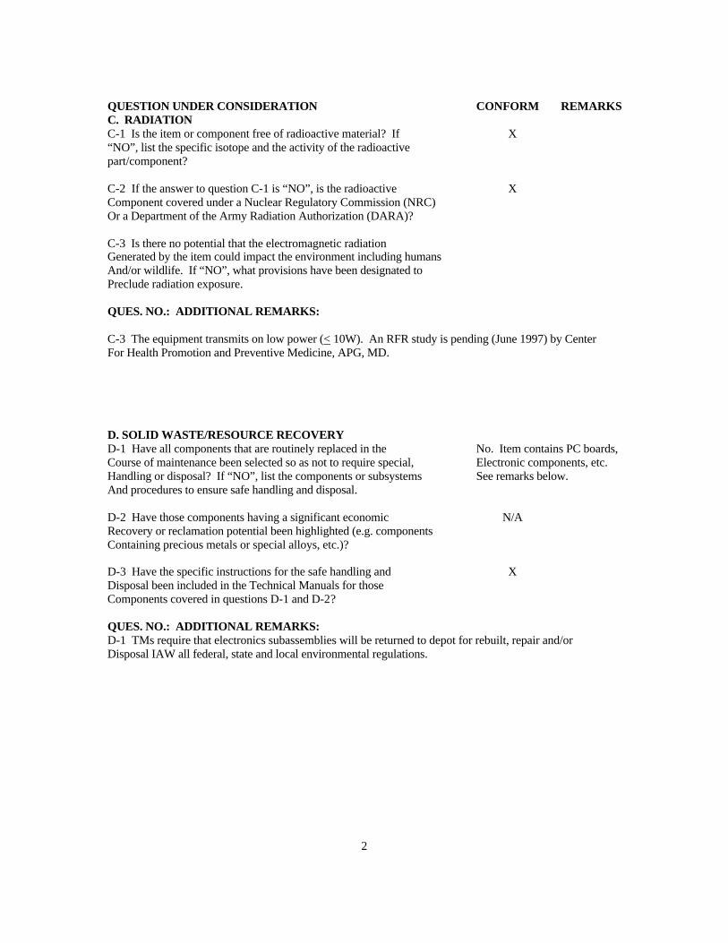
QUESTION UNDER CONSIDERATION CONFORM REMARKS C. RADIATION C-1 Is the item or component free of radioactive material? If “NO”, list the specific isotope and the activity of the radioactive part/component?
X
C-2 If the answer to question C-1 is “NO”, is the radioactive Component covered under a Nuclear Regulatory Commission (NRC) Or a Department of the Army Radiation Authorization (DARA)?
X
C-3 Is there no potential that the electromagnetic radiation Generated by the item could impact the environment including humans And/or wildlife. If “NO”, what provisions have been designated to Preclude radiation exposure.
QUES. NO.: ADDITIONAL REMARKS:
C-3 The equipment transmits on low power (< 10W). An RFR study is pending (June 1997) by Center For Health Promotion and Preventive Medicine, APG, MD. D. SOLID WASTE/RESOURCE RECOVERY D-1 Have all components that are routinely replaced in the Course of maintenance been selected so as not to require special, Handling or disposal? If “NO”, list the components or subsystems And procedures to ensure safe handling and disposal.
No. Item contains PC boards, Electronic components, etc. See remarks below.
D-2 Have those components having a significant economic Recovery or reclamation potential been highlighted (e.g. components Containing precious metals or special alloys, etc.)?
N/A
D-3 Have the specific instructions for the safe handling and Disposal been included in the Technical Manuals for those Components covered in questions D-1 and D-2?
X
QUES. NO.: ADDITIONAL REMARKS: D-1 TMs require that electronics subassemblies will be returned to depot for rebuilt, repair and/or Disposal IAW all federal, state and local environmental regulations.
2
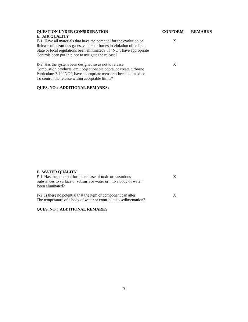
QUESTION UNDER CONSIDERATION CONFORM REMARKS E. AIR QUALITY E-1 Have all materials that have the potential for the evolution or Release of hazardous gases, vapors or fumes in violation of federal, State or local regulations been eliminated? If “NO”, have appropriate Controls been put in place to mitigate the release?
X
E-2 Has the system been designed so as not to release Combustion products, emit objectionable odors, or create airborne Particulates? If “NO”, have appropriate measures been put in place To control the release within acceptable limits?
X
QUES. NO.: ADDITIONAL REMARKS:
F. WATER QUALITY F-1 Has the potential for the release of toxic or hazardous Substances to surface or subsurface water or into a body of water Been eliminated?
X
F-2 Is there no potential that the item or component can alter The temperature of a body of water or contribute to sedimentation?
X
QUES. NO.: ADDITIONAL REMARKS
3
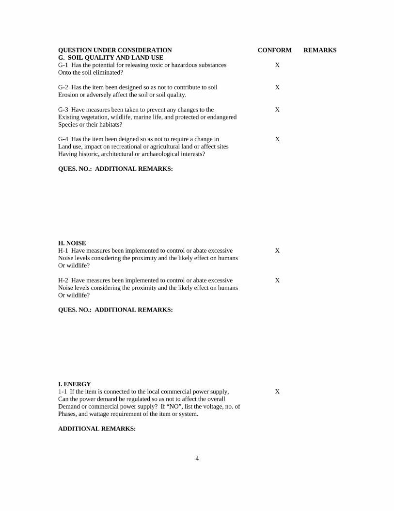
QUESTION UNDER CONSIDERATION CONFORM REMARKS G. SOIL QUALITY AND LAND USE G-1 Has the potential for releasing toxic or hazardous substances Onto the soil eliminated?
X
G-2 Has the item been designed so as not to contribute to soil Erosion or adversely affect the soil or soil quality.
X
G-3 Have measures been taken to prevent any changes to the Existing vegetation, wildlife, marine life, and protected or endangered Species or their habitats?
X
G-4 Has the item been deigned so as not to require a change in Land use, impact on recreational or agricultural land or affect sites Having historic, architectural or archaeological interests?
X
QUES. NO.: ADDITIONAL REMARKS:
H. NOISE H-1 Have measures been implemented to control or abate excessive Noise levels considering the proximity and the likely effect on humans Or wildlife?
X
H-2 Have measures been implemented to control or abate excessive Noise levels considering the proximity and the likely effect on humans Or wildlife?
X
QUES. NO.: ADDITIONAL REMARKS:
I. ENERGY 1-1 If the item is connected to the local commercial power supply, Can the power demand be regulated so as not to affect the overall Demand or commercial power supply? If “NO”, list the voltage, no. of Phases, and wattage requirement of the item or system.
X
ADDITIONAL REMARKS:
4
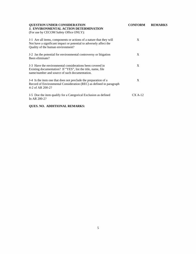
QUESTION UNDER CONSIDERATION CONFORM REMARKS J. ENVIRONMENTAL ACTION DETERMINATION (For use by CECOM Safety Office ONLY):
J-1 Are all items, components or actions of a nature that they will Not have a significant impact or potential to adversely affect the Quality of the human environment?
X
J-2 Jas the potential for environmental controversy or litigation Been eliminate?
X
J-3 Have the environmental considerations been covered in Existing documentation? If “YES”, list the title, name, file name/number and source of such documentation.
X
J-4 Is the item one that does not preclude the preparation of a Record of Environmental Consideration (REC) as defined in paragraph 4-2 of AR 200-2?
X
J-5 Doe the item qualify for a Categorical Exclusion as defined In AR 200-2?
CX A-12
QUES. NO. ADDITIONAL REMARKS:
5
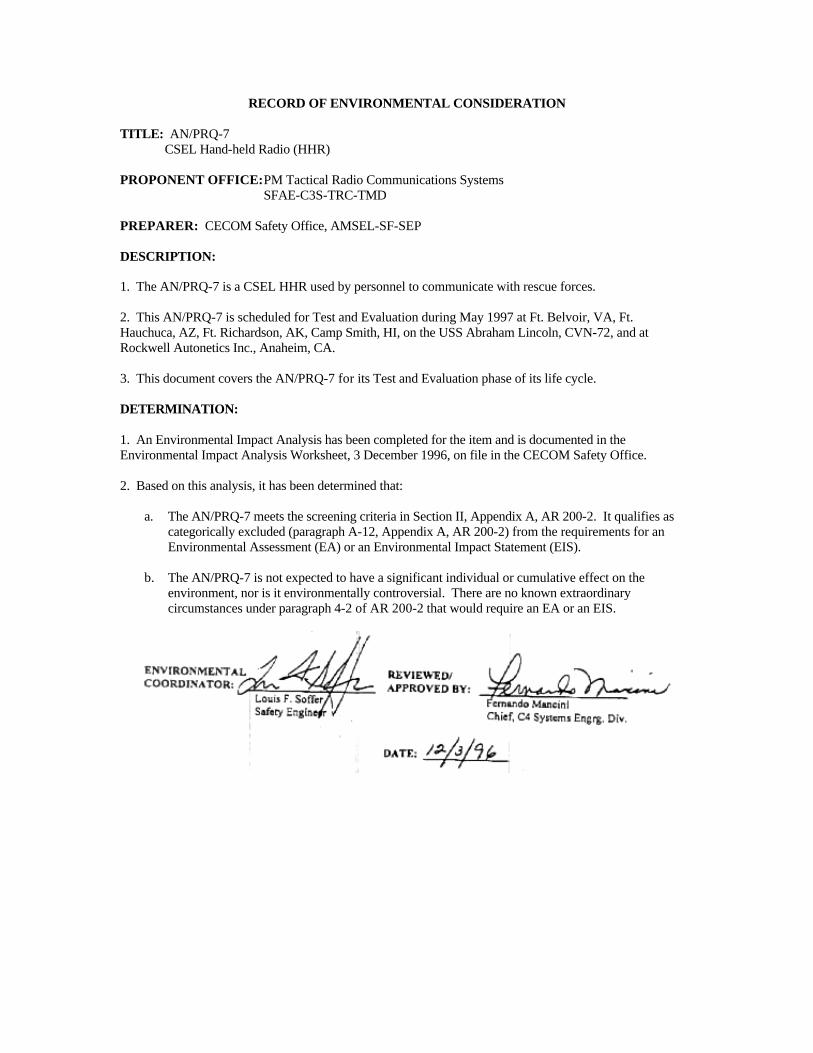
RECORD OF ENVIRONMENTAL CONSIDERATION TITLE: AN/PRQ-7 CSEL Hand-held Radio (HHR) PROPONENT OFFICE: PM Tactical Radio Communications Systems SFAE-C3S-TRC-TMD PREPARER: CECOM Safety Office, AMSEL-SF-SEP DESCRIPTION: 1. The AN/PRQ-7 is a CSEL HHR used by personnel to communicate with rescue forces. 2. This AN/PRQ-7 is scheduled for Test and Evaluation during May 1997 at Ft. Belvoir, VA, Ft. Hauchuca, AZ, Ft. Richardson, AK, Camp Smith, HI, on the USS Abraham Lincoln, CVN-72, and at Rockwell Autonetics Inc., Anaheim, CA. 3. This document covers the AN/PRQ-7 for its Test and Evaluation phase of its life cycle. DETERMINATION: 1. An Environmental Impact Analysis has been completed for the item and is documented in the Environmental Impact Analysis Worksheet, 3 December 1996, on file in the CECOM Safety Office. 2. Based on this analysis, it has been determined that:
a. The AN/PRQ-7 meets the screening criteria in Section II, Appendix A, AR 200-2. It qualifies as categorically excluded (paragraph A-12, Appendix A, AR 200-2) from the requirements for an Environmental Assessment (EA) or an Environmental Impact Statement (EIS).
b. The AN/PRQ-7 is not expected to have a significant individual or cumulative effect on the
environment, nor is it environmentally controversial. There are no known extraordinary circumstances under paragraph 4-2 of AR 200-2 that would require an EA or an EIS.
APPENDIX D
MATERIAL SAFETY DATA SHEET (MSDS) LiSO2 BATTERY
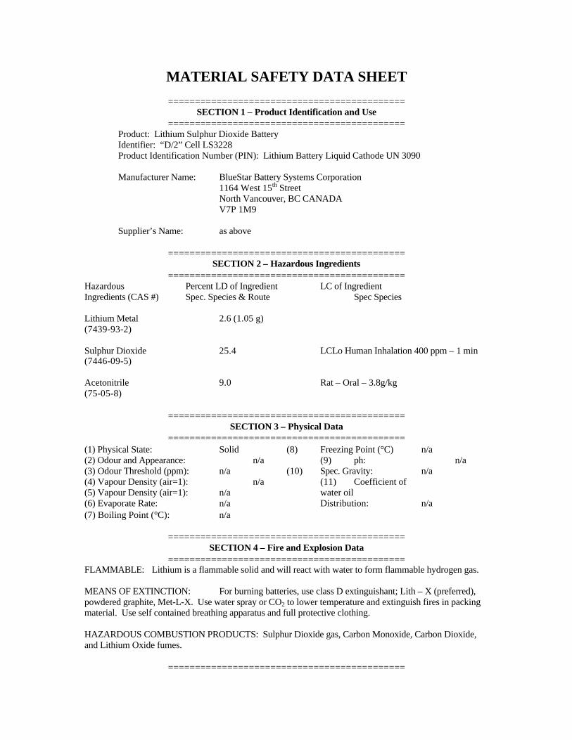
MATERIAL SAFETY DATA SHEET
============================================ SECTION 1 – Product Identification and Use
============================================ Product: Lithium Sulphur Dioxide Battery Identifier: “D/2” Cell LS3228 Product Identification Number (PIN): Lithium Battery Liquid Cathode UN 3090 Manufacturer Name: BlueStar Battery Systems Corporation 1164 West 15th Street North Vancouver, BC CANADA V7P 1M9 Supplier’s Name: as above
============================================ SECTION 2 – Hazardous Ingredients
============================================ Hazardous Percent LD of Ingredient LC of Ingredient Ingredients (CAS #) Spec. Species & Route Spec Species Lithium Metal 2.6 (1.05 g) (7439-93-2) Sulphur Dioxide 25.4 LCLo Human Inhalation 400 ppm – 1 min (7446-09-5) Acetonitrile 9.0 Rat – Oral – 3.8g/kg (75-05-8)
============================================ SECTION 3 – Physical Data
============================================ (1) Physical State: Solid (8) Freezing Point (°C) n/a (2) Odour and Appearance: n/a (9) ph: n/a (3) Odour Threshold (ppm): n/a (10) Spec. Gravity: n/a (4) Vapour Density (air=1): n/a (11) Coefficient of (5) Vapour Density (air=1): n/a water oil (6) Evaporate Rate: n/a Distribution: n/a (7) Boiling Point (°C): n/a
============================================ SECTION 4 – Fire and Explosion Data
============================================ FLAMMABLE: Lithium is a flammable solid and will react with water to form flammable hydrogen gas. MEANS OF EXTINCTION: For burning batteries, use class D extinguishant; Lith – X (preferred), powdered graphite, Met-L-X. Use water spray or CO2 to lower temperature and extinguish fires in packing material. Use self contained breathing apparatus and full protective clothing. HAZARDOUS COMBUSTION PRODUCTS: Sulphur Dioxide gas, Carbon Monoxide, Carbon Dioxide, and Lithium Oxide fumes.
============================================
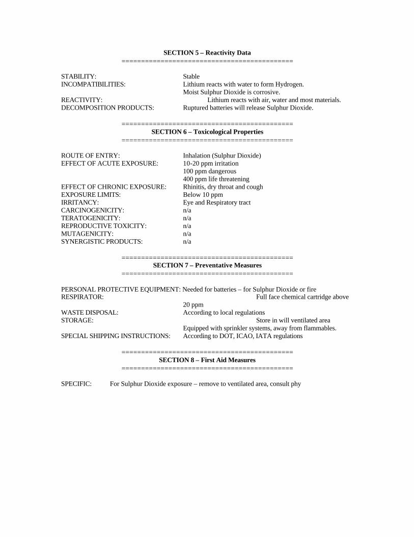
SECTION 5 – Reactivity Data ============================================
STABILITY: Stable INCOMPATIBILITIES: Lithium reacts with water to form Hydrogen. Moist Sulphur Dioxide is corrosive. REACTIVITY: Lithium reacts with air, water and most materials. DECOMPOSITION PRODUCTS: Ruptured batteries will release Sulphur Dioxide.
============================================ SECTION 6 – Toxicological Properties
============================================
ROUTE OF ENTRY: Inhalation (Sulphur Dioxide) EFFECT OF ACUTE EXPOSURE: 10-20 ppm irritation 100 ppm dangerous 400 ppm life threatening EFFECT OF CHRONIC EXPOSURE: Rhinitis, dry throat and cough EXPOSURE LIMITS: Below 10 ppm IRRITANCY: Eye and Respiratory tract CARCINOGENICITY: n/a TERATOGENICITY: n/a REPRODUCTIVE TOXICITY: n/a MUTAGENICITY: n/a SYNERGISTIC PRODUCTS: n/a
============================================ SECTION 7 – Preventative Measures
============================================
PERSONAL PROTECTIVE EQUIPMENT: Needed for batteries – for Sulphur Dioxide or fire RESPIRATOR: Full face chemical cartridge above 20 ppm WASTE DISPOSAL: According to local regulations STORAGE: Store in will ventilated area Equipped with sprinkler systems, away from flammables. SPECIAL SHIPPING INSTRUCTIONS: According to DOT, ICAO, IATA regulations
============================================ SECTION 8 – First Aid Measures
============================================
SPECIFIC: For Sulphur Dioxide exposure – remove to ventilated area, consult phy
APPENDIX E
CSEL ELECTROMAGNETIC RADIATION (EMR) HAZARDS ANALYSIS – CAMP SMITH, HAWAII
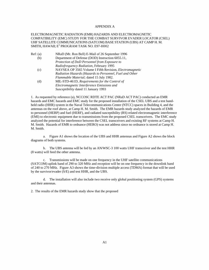
APPENDIX A
ELECTROMAGNETIC RADIATION (EMR) HAZARDS AND ELECTROMAGNETIC COMPATIBILITY (EMC) STUDY FOR THE COMBAT SURVIVOR EVADER LOCATOR (CSEL) UHF SATELLITE COMMUNICATIONS (SATCOM) BASE STATION (UBS) AT CAMP H. M. SMITH, HAWAII; E3 PROGRAM TASK NO. E97-H002 Ref: (a) NRaD (Mr. Ron Bell) E-Mail of 26 September 1996 (b) Department of Defense (DOD) Instruction 6055.11, Protection of DoD Personnel from Exposure to Radiofrequency Radiation, February 1995 (c) NAVSEA OP 3565 Volume I Fifth Revision, Electromagnetic Radiation Hazards (Hazards to Personnel, Fuel and Other Flammable Material; dated 15 July 1982. (d) MIL-STD-461D, Requirements for the Control of Electromagnetic Interference Emissions and Susceptibility dated 11 January 1993 1. As requested by reference (a), NCCOSC RDTE ACT PAC (NRaD ACT PAC) conducted an EMR hazards and EMC hazards and EMC study for the proposed installation of the CSEL UBS and a test hand-held radio (HHR) system in the Naval Telecommunications Center (NTCC) spaces in Building 4, and the antennas on the roof above, at Camp H. M. Smith. The EMR hazards study analyzed the hazards of EMR to personnel (HERP) and fuel (HERF), and radiated susceptibility (RS) related electromagnetic interference (EMI) to electronic equipment due to transmissions from the proposed CSEL transceivers. The EMC study analyzed the potential for interference between the CSEL transceivers and existing RF systems at Camp H. M. Smith. Hazards of EMR to ordnance (HERO) was not address since no ordnance is stored at Camp H. M. Smith.
a. Figure A1 shows the location of the UBS and HHR antennas and Figure A2 shows the block diagrams of both systems.
b. The UBS antenna will be fed by an AN/WSC-3 100 watts UHF transceiver and the test HHR (8 watts) will feed the other antenna.
c. Transmissions will be made on one frequency in the UHF satellite communications (SATCOM) uplink band of 290 to 320 MHz and reception will be on one frequency in the downlink band of 240 to 270 MHz. Figure A3 shows the time-division multiple access (TDMA) format that will be used by the survivor/evader (S/E) and test HHR, and the UBS.
d. The installation will also include two receive only global positioning system (GPS) systems and their antennas. 2. The results of the EMR hazards study show that the proposed
A1
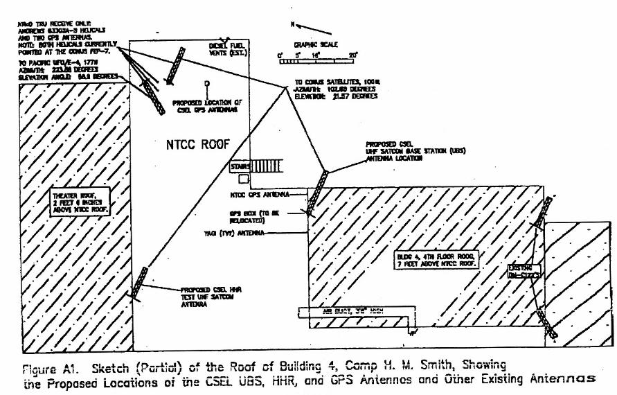
SUBJECT: FORWARDING OF APPENDIX A OF BESEP FOR NTCC CAMP H.M. SMITH COMBAT SURVIVOR/EVADER LOCATOR (CSEL) INSTALLATION
Copy to: COMNAVCOMTELCOM (G. WILLIAMS) NCTAMB EASTPAC (Code N5) NTCC Camp H.M. Smith, Hawaii (CW03 Timmie) UBCINCPAC (Code j0) SMC/CZJ Los Angeles AFB El Segundo, CA (LT Prindiville) JICPAC (Code IA) JRCC Honolulu, Hawaii (LT COL Peterson) Boeing North America, Inc, Anaheim, CA (R. Gilden) SARSAT USMCC Suitland, MD (LT Moran) NR aD San Diego, Ca ( Code D824) D9121MI D9121AS D9111RS LIBRARY
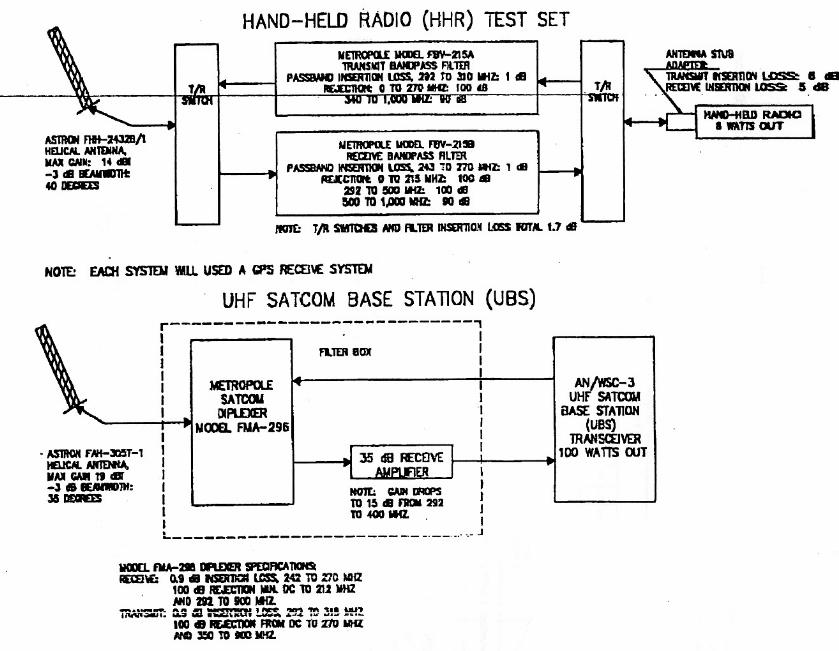
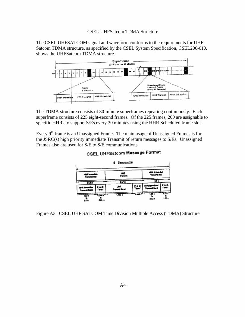
CSEL UHFSatcom TDMA Structure The CSEL UHFSATCOM signal and waveform conforms to the requirements for UHF Satcom TDMA structure, as specified by the CSEL System Specification, CSEL200-010, shows the UHFSatcom TDMA structure.
The TDMA structure consists of 30-minute superframes repeating continuously. Each superframe consists of 225 eight-second frames. Of the 225 frames, 200 are assignable to specific HHRs to support S/Es every 30 minutes using the HHR Scheduled frame slot. Every 9th frame is an Unassigned Frame. The main usage of Unassigned Frames is for the JSRC(s) high priority immediate Transmit of return messages to S/Es. Unassigned Frames also are used for S/E to S/E communications
Figure A3. CSEL UHF SATCOM Time Division Multiple Access (TDMA) Structure
A4
CSEL installation will not create HERP or HERF to personnel in accessible areas or fuel storage or handling areas, respectively. UBS transmissions may cause RS related EMI in the NTCC GPS whose antenna is next to the UBS’s. The EMC study did not predict EMI problems due to the proposed CSEL installation. 3. EMR Hazards Criteria:
a. HERP: HERP from electromagnetic fields is due to the thermal heating of human tissue. Reference (b) provides the latest DoD HERP exposure limits to which the Navy exposure limits are being revised to. Reference (b) includes a two-tier exposure criteria for controlled and uncontrolled environments.
(1) Controlled environments are defined as areas where exposure may be incurred by personnel who are aware of the potential for radio frequency (RF) exposures as a concomitant of employment or duties, exposure of individuals who knowingly enter areas where higher RF levels can reasonably be anticipated to exist, and exposure that may occur incidental to transient passage through such areas. The permissible exposure limit (PEL) fro controlled environments is applicable to the roof of Building 4 and all working areas beneath the roof.
(2) Uncontrolled environments are defined as public areas where individuals have no knowledge or control of their exposure. Such areas generally represent living quarters, workplaces, or public areas were personnel would not expect to encounter higher levels of RF energy. There are stricter limits for these areas. The PEL for uncontrolled environments is applicable to the areas accessible to the general public on the second floor of Building 4.
b. HERF: HERF is the ignition of fuel vapor by arcing or ignition of fuel in contact With RF heated metal in intense RF fields. These fuels include AVGAS, MOGAS, and JP-4. Diesel and JP-5 fuel are not vulnerable to RF arcs due to their low vapor pressure at ordinary temperatures. The HERF hazard energy levels and recommended separation distances are promulgated by reference (c). The minimum recommended separation distance at shore sites is 15 meters (50 feet) for communications transmitters radiating 250 watts or less and 60 meter (200 feet) for transmitters radiating more than 250 watts. Additionally, for transmitters radiating more than 250 watts, the generated E-field at the fueling site must be no greater than would exist at a distance of 15 meters from 250 watts radiated output (5.77 v/m calculated). The 5.77 V/m criteria can also be applied to lower power transmitters.
c. MIL-STD-461D ELECTRONIC EQUIPMENT SUSCEPTIBILITY: Electronic equipment and subsystems are susceptible to RF fields.
A5
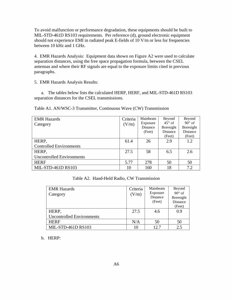
To avoid malfunction or performance degradation, these equipments should be built to MIL-STD-461D RS103 requirements. Per reference (d), ground electronic equipment should not experience EMI in radiated peak E-fields of 10 V/m or less for frequencies between 10 kHz and 1 GHz. 4. EMR Hazards Analysis: Equipment data shown on Figure A2 were used to calculate separation distances, using the free space propagation formula, between the CSEL antennas and where their RF signals are equal to the exposure limits cited in previous paragraphs. 5. EMR Hazards Analysis Results:
a. The tables below lists the calculated HERP, HERF, and MIL-STD-461D RS103 separation distances for the CSEL transmissions. Table A1. AN/WSC-3 Transmitter, Continuous Wave (CW) Transmission EMR Hazards Category
Criteria (V/m)
Mainbeam Exposure Distance
(Feet)
Beyond 45” of
Boresight Distance
(Feet)
Beyond 90” of
Boresight Distance
(Feet) HERP, Controlled Environments
61.4 26 2.9 1.2
HERP, Uncontrolled Environments
27.5 58 6.5 2.6
HERF 5.77 278 50 50 MIL-STD-461D RS103 10 160 18 7.2
Table A2. Hand-Held Radio, CW Transmission
EMR Hazards Category
Criteria (V/m)
Mainbeam Exposure Distance
(Feet)
Beyond 90° of
Boresight Distance
(Feet) HERP, Uncontrolled Environments
27.5 4.6 0.9
HERF N/A 50 50 MIL-STD-461D RS103 10 12.7 2.5
b. HERP:
A6
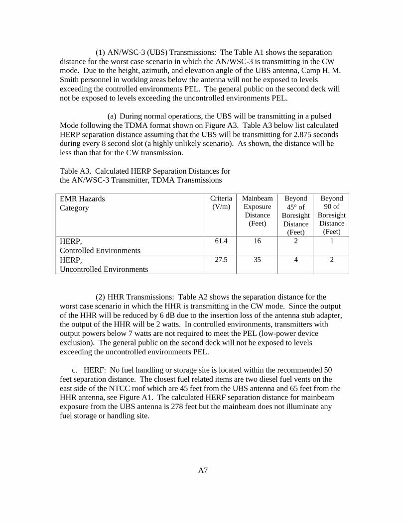
(1) AN/WSC-3 (UBS) Transmissions: The Table A1 shows the separation distance for the worst case scenario in which the AN/WSC-3 is transmitting in the CW mode. Due to the height, azimuth, and elevation angle of the UBS antenna, Camp H. M. Smith personnel in working areas below the antenna will not be exposed to levels exceeding the controlled environments PEL. The general public on the second deck will not be exposed to levels exceeding the uncontrolled environments PEL.
(a) During normal operations, the UBS will be transmitting in a pulsed Mode following the TDMA format shown on Figure A3. Table A3 below list calculated HERP separation distance assuming that the UBS will be transmitting for 2.875 seconds during every 8 second slot (a highly unlikely scenario). As shown, the distance will be less than that for the CW transmission. Table A3. Calculated HERP Separation Distances for the AN/WSC-3 Transmitter, TDMA Transmissions EMR Hazards Category
Criteria (V/m)
Mainbeam Exposure Distance
(Feet)
Beyond 45° of
Boresight Distance
(Feet)
Beyond 90 of
Boresight Distance
(Feet) HERP, Controlled Environments
61.4 16 2 1
HERP, Uncontrolled Environments
27.5 35 4 2
(2) HHR Transmissions: Table A2 shows the separation distance for the worst case scenario in which the HHR is transmitting in the CW mode. Since the output of the HHR will be reduced by 6 dB due to the insertion loss of the antenna stub adapter, the output of the HHR will be 2 watts. In controlled environments, transmitters with output powers below 7 watts are not required to meet the PEL (low-power device exclusion). The general public on the second deck will not be exposed to levels exceeding the uncontrolled environments PEL.
c. HERF: No fuel handling or storage site is located within the recommended 50 feet separation distance. The closest fuel related items are two diesel fuel vents on the east side of the NTCC roof which are 45 feet from the UBS antenna and 65 feet from the HHR antenna, see Figure A1. The calculated HERF separation distance for mainbeam exposure from the UBS antenna is 278 feet but the mainbeam does not illuminate any fuel storage or handling site.
A7
d. MIL-STD-461D RS103 Related EMT for Ground Electronic Equipment: No Camp H. M. Smith electronic equipment will be subject to mainbeam illumination from either the UBS or HHR antenna. Electronic equipment immediately below these antennas may be within the calculated RS103 separation distances, however due to an estimated 10 dB roof attenuation, the 10 V/m level should not be exceed beneath the roof of Building 4. The NTCC GPS system whose antenna is located 5 feet from the UBS antenna will be relocated if radiated susceptibility related EMI occurs. 6. EMC Analysis Results
a. Co-channel and Adjacent Channel Interference: No co-channel interference is predicted since the CSEL frequency will be assigned by the UHF SATCOM frequency manager who controls all UHF SATCOM frequency assignments. Noise monitoring of the UHF SATCOM downlink band showed several UHF communication transmissions at 257.790, 267.800, and 269.000 MHz but all below –72 dBm (picked up with a Dorne Margolin C-121 antenna). None of these should interfere with UHF SATCOM downlink frequencies.
b. Transmitter Spurious Interference: The transmitter spurious rejections for the AN/WSC-3 and HHR are 80 dB and 60 dB (typical for HHR’s), respectively. Additionally, both the UBS and HHR transmit outputs will be filtered by 100 dB from DC to 270 MHz and 90 dB above 340 MHz, see Figure A2. Calculations show that the UBS and HHR transmissions should not create transmitter spurious EMI for each other, the nearby NRaD TRU UHF SATCOM receive only system, or the existing CINCPAC UHF SATCOM and other line of sight systems on Building 4 or on Building 1. The transmit filtering for the AN/WSC-3 and HHR will also prevent harmonic interference.
c. Receiver Spurious Response Interference: Calculations show that no receiver spurious response interference is predicted due to the separation between the proposed UBS and HHR antennas and the existing NRaD TRU, and CINCPAC RF antennas, and the fact that the UBS, HHR, and NRaD TRU systems are equipped with receive filters. The calculated signal levels of the transmitted UBS and HHR signals at the output of the NRaD TRU receive amplifiers are below –30 dBm. These levels are well below the +10 dBm +1 dB gain compression point of the NRaD TRU RF amplifiers.
d. Intermodulation Product EMI: Due to the separation of the various RF systems and the fact that the UBS and HHR will not transmit concurrently due to the TDMA format, intermodulation product EMI is not predicted.
A8
7. Conclusions and Recommendations: Based on the analysis, the proposed CSEL installation is not predicted to cause HERP, HERF, or EMC problems for personnel in normally accessible areas, fuel, or existing RF systems, respectively. Radiated susceptibility EMI problems may be experienced by the NTCC GPS antenna next to the UBS.
a. To avoid HERP, we recommend the following action:
Post a “KEEP MOVING” RF warning sign (see Figure A4) at the base of the UBS and HHR antenna poles. Advise maintenance personnel to secure the transmitter when work is performed on the UBS and HHR antenna or RF cables, or if any other work will be done within 3 feet of the UBS antenna.
b. The NTCC GPS antenna will be relocated if EMI is experienced. 8. Our point of contact for this report is Mr. Steve Kobashigawa, DSN (315) 471-1976 or commercial (808) 471-1976.
A9