Embed Size (px)
Citation preview
Report of the Committee on Vehicular Alternative Fuel Systems
Douglas B. Home, Chair Atlanta Gas Light Co,, GA [U]
Rep. American Gas Assn.
Nancy C. Pehrson, Secretary Minnegasco, Inc., MN [U]
Ronald C. Adcock, M&M Protection Consultants, IL, [I] Roy E. Adkins, Cryogenic Fuels, Inc., VA [IM] Dennis K. Boone, Metropolitan Transit Authority (METRO), TX [U] Robin Nell Borland, Amcast - Superior Valve Co., PA[M]
Rep. Compressed Gas Assn. C. Everett Brett, The University of Alabama, AL [SE] Daniel F. Brock, Wrentham Fire Dept., MA [E] Richard Cacini, U.S. Dept. of Transportation, OK [E] Philip F. Clasen, Jr., Amoco Production Co., TX [U] Don H. Coers, Chicago Bridge & Iron Co., IL [M] Robert B. DeRemer, Int ' l Approval Services, OH [U]
Rep. American Gas Assn. ohn B. Dimmick, Pressed Steel Tank Co. Inc., WI [M] onald E. Dockray, The Gas Co., CA [U]
Douglas W. Dunford, Norfllwest Natural Gas Co., OR [U] Thomas J. Forsythe, Gage-Babcock & Assoc., CA [SE] Albert G. Garlatti, Intertek Testing Services NA Inc., MN [R/T] Keith W. Gustafsoe, MVE Cryogenic, GA [M] Richard A. Hoffmann, Hoffmann & Feige, Inc_, NY [SE] Marshall Issen, Underwriters Laboratories Inc., IL [RT] Glen P,. Marshall, Shell Oil Co., TX [M]
Rep. American Petroleum Inst. Scott C. Nason, Process Engr Inc., NH [M] Lawrence D. Peterson, FordMotor Co., MI [M] Robert E. Petsinger, CNG Services of Pittsburgh Inc., PA [IM] Ralph Rackham, FuelMaker Corp., ON, Canada [M] Henry W. Renfrew, Compliance and Response Mgmt., CT [SE]
ReD. Fire Marsh,'ds Assn. of North America FredP . Snyder, Essex Cryogenics of Missouri, Inc., MO [M] James H. Stannard, Jr., Stannard & Co., NJ [SE]
Alternates
Mario A. Antonettl, Gage-Babcock & Assn. Inc., NY [SE] (Ah. to T . j . Forsythe)
Mervln E. Bohrer, Jr., Bauer Compressors, Inc., VA [M] (Alt. to IL Rackham)
Wayne Doversberger, Underwriters Laboratories Inc., IL [RT] (Alt. to M. Issen)
Robert J. Faker, King County, WA [11] (Alt. to D. K. Boone)
Dale Geren, Essex Cryogenics of Missouri, Inc., MO [M] (Air. to F. P Snyder)
James P. Lewis, Project Technical Liaison Assoc., Inc., TX [SE] (Alt. toJ. H. Stannard)
Kenneth L. Paul, Process Engr Inc., NH [M] (Alt. to S. C. Nason)
George D. Rhoades, Liquid Carbonic Industries Corp., IL [M] (Air. to D. H. Coers)
Nonvoting
Beuoit Leduc, Natural Gas Technologies Ctr., PQ, Canada Rep. Canadian Gas Assn.
Staff Liaison: Theodore C. Lemoff
This list rqOresents the membership at the time the Committee was balloted on the text of this edition. Since that time, changes in the membership may have occurred. A key to classifications is found at the back of this document.
Committee Scope: This Committee shall have primary responsibility .f°r documents, on fire and expiosion hazards associated with compressed natural gas (CNG) and liquefied natural gas (LNG) engine fuel systems on vehicles of all types and for refueling stations and associated storage.
The Committee shall coordinate its documents with the Committee on the National Fuel Gas Code with respect to natural gas piping within the scope of that Committee, with the Committees on Industrial Trucks, Fire Safety for Recreational Vehicles, and Marine Fire Protection with respect to engine fuel systems and refueling stations within their scopes, and with the Liquefied Natural Gas Committee with respect to storage of LNG within its scope.
The Report of the Technical Committee on Vehicular Alternative Fuel Systems is presented for adoption.
This Report was prepared by file Technical Committee on Vehicular Alternative Fuel Systems and proposes for adoption amendments to NFPA 52-1995, Standard for Compressed Natural Gas (CNG) Vehicular Fuel Systems. NFPA 52-1995 is published in Volume 2 of the 1997 National Fire Codes and in separate pamphlet form.
This Report has been submitted to letter ballot of the Technlca/Commlt tee on Vehicular Alternative Fuel Systems, which consists of 28 voting members. The results of the balloting, after circulation of any negative votes, can be found in the report.
314
N F P A 52 - - A 9 8 R O P
(Log #91) 52- 1 - (Entire Document): Reject , SUBMITTER: Robert L. Mauro, Nat I Hydrogen Assn. R E C O M M E N D A T I O N : NHA proposes t ha t the cornrnig-tee addresses hydrogen
vehicular fuel systems. SUBSTANTIATION: The only alternative fueled vehicles covered in NFPA standards are for CNG, LNG, and LPG fueled vehicles. Hydrogen fueled vehicles are also being refueled and being driven on public roadways, and the lack o f a consensus standard has caused, and will continue to cause difficulties for vehicle developers, vehlcle/fleet operators, refueling station developers/operators, and authorities having jurisdiction for hydrogen vehicle safety. COMMrrrEE ACTION: Reject~ COMMITTEE STATEMENT: The Committee does not a~ree that hydrogen should be added to NFPA 52. The Committee heard a presentation from a representative of the National Hydrogen Association and established a task force to make recommendations on creating a new standard covering hydrogen fueled vehicles. NUMBER OF COMMITTEE MEMBERS ELIGIBLE TO VOTE: 28 VOTE ON COMMITTEE ACTION:
AFFIRMATIVE: 23 NOT RETURNED: 5 Borland, Brock, Clasen, Dunford,
Peterson
(Log #CP9) 52- 2 - (Various Sections): Accept SUBMFrTER: Technical Committee on Vehicular Alternative Fuel Systems R E C O M M E N D A T I O N :
Revise ~ ' P A 52, various sections as follows: 1. Relocate all notes to Appendix A.
2. Revise 1-1 to read: 1-1" Scope. This standard shall apply' r.~I '=: to the design and
installation of compressed natural gas (CNG) engine fuel systems on vehicles of all types, including
(a) Ori~nal Equipment Manufacturers. (b) Vehicle Converters ~ft=.-:::..z.-k=t and (c) Vehicle a~.d t~, ~:-:'." : : : : - = : : d fueling (dispensing)
systems. . Exception: Unchanged.
3. Revise the definition of Cylinder to read: Cylinder. A container constructed, inspected, and maintained
in accordance with I), $. Department O f Transnortation or regulations or ANSI/AGA I~GV2, Basic
Requirements for Compressed Natural Gas Vehicle (NGV) Fuel Containers, or C~A BS1, Boiler, Pressure Vessel and Pressure Piping Code.
4. Revise the definition of Limited-Combustible Material to read:
Limited-Combustible Material.* A material (as defined in NFPA 220, Standard on Types of Building Construction) that does not comply with the definition of noncombustible material and that, in the form in which it is used, has a potential heat value not exceeding 3500 Btu/lb (8141 kJ/kg) and complies with either (a) or (b), w!:!c!: c.=!!:;~. Materials subject to increase in combustibility or flame spread rating, beyondthe limits herein established, through the effects of age, moisture, or other atmospheric condhion shall be considered combustible.
(a) Materials having a structural base of noncombustible material, with a surfacgh~ not exceeding a thickness of 1/8 in. (3.2 mm) that has a flame spread rating not greater than 50.
(b) Materials, in the form and thickness used, other than as described in (a), having neither a flame spread rating greater than 25 nor evidence of continued progressive combustion and of such composition that surfaces that would be exposed by cutting through the material on any plane would have neither a flame spread rating greater than 25 nor evidence of continued progressive combustion.
5. Revise 2-4.2 to read: 2-4.2 The container shall be designed ~ ~: ::~m~!: for CNG
service and shall be permanently marked "CNG" by the manufacturer.
6. Revise 2-4.5 to read: 2-4.5 PressurL" vessels shall be manufactured, inspected,
marked, and tested in accordance with ASME Boiler and Pressure Vessel Code ~==!:: for tl:: C~: ' . : ' . . - :z~ ~f U :~ r :~ P : := : : : : Vc:-c.*:, Section VIII, D".: ' : ' : : I :.: 2, or ?~.*.**E E:.'I:r -::d
P . - : : : : r : V:~: ! C ~ : , Section X, and shall be suitable for C~G service. Adherence to applicable ASME Boiler and Pressure Vessel Code case interpretations and addenda shall be considered as compliance with the ASME Boiler and Pressure Vessel Code.
7. Revise 2-4.7 to read: 2-4.7 Welding or brazing for the repair or alteration of an ASME
pressure vessel shall comply with the documents under which the pressure vessel was fabricated. Other welding or brazing shall be permitted only on saddle plates, lugs, or brackets attached to the pressure vessel by the. pressure vessel manufacturer. . .
The exchang.e or interchange of pressure vessel (see defmluon) appurtenances intended for the same purpose shall not be considered a repair or alteration.
8. Revise 2-5.2.2 to read: 2-5.2.2 Pressure relief valves for CNG service shall not be fi~ed
with lifting devices. The adjustment, if external, shall be provided with a means for seaiingthe adjustment to prevent tampering by unauthorized persons. If at any time it is necessary to break such a seal, the valve shall be removed from service until it has been reset and sealed. Any Adjustments necessary shall be made only by the manufacturer or other companies having competent personnel and adequate facilities for the repair, adjustment, and testing of such valves. The organization making such adjustment shall attach a permanent tag with the setting, capacity, and date. Pressure relief valves protecting ASME pressure vessels shall be repaired, adjusted, and tested in accordance with the ASME Boiler and Pressure Vessel Code.
9. Revise 2-8.4(d), Exception No. 1 to read: 2-8.4(d) Exception No. I: The refueling connection shall be
permitted to be made of nonsparking wrought aluminum alloy suitable designed for the pressure employed.
10. Revise 2-9.1 to read: 2-9.1 Valves, valve packing, and gaskets shall be suitable
designed or selected for the fuel over the full range of pressures and temperatures to which they can be subjected under normal operating conditions.
Shutoff valves shall have a rated service pressure not less than the rated service pressure of the entire system and shall be capable of withstanding a hydrostatic test of at least four times the rated service pressure without rupture. Leakage shall not occur at less than 11/2 one-and-a-half times the rateo service pressure, using dry air as the test medium.
11. Revise 2-10.1 toread: 2-10.1 Hose and metallic hose shall be constructed of or lined
with materials that are resistant to corrosion and the actions exposure to of natural gas.
12. Revise 2-10.2 to read: 2-10.2 Hose, metallic hose, flexible metal hose, tubing, and
their connections shall be suitable designed or selected for the most severe pressures and temperatures expected under normal operating conditions with a burst pressure of at least four times the service pressure.
13. Revise 3-2.2 to read: 3-2.2 Components in the engine compartment shall be suitable
designed or selected for service for at a temperature range of - 40°F to 250°F (-40°C to 121°C). All other components shall be suitable designed or selected for service for a range of--40°F to 180°F (--40°C to 82.2°C).
14. Revise $-3.2.2 to read: 3-3.2.2 No portion of a fuel supply container or container
appurtenance shall be located ahead of the front axle or behind tile rear bumper mounting face of a vehicle point of attachment of the rear bumper to the vehicle. Container valves shall be protected from physical damage using the vehicle structure, valve srotectors, or a suitable metal shield. 15. Revise 3-3.10 to read: 3-3.10 A container, Where located in a vehicle compartment
apable of accumulating natural gas, a container shall be astalled so that: (a) The pressure relief device for the protection of the
container is installed in the same vehicle compartment as the container,
(b) The discharge from the pressure relief device is (a) Vented to the outside through a metallic tube or hose no smaller than the outlet diameter of the relief device, secured at 12-in. (300- mm) intervals where the tube exceeds 24 in. (610 mm) in length, and.having a minimum burst pressure of at least 11/2 times the service pressure of the container at 400°F (204°C).
(c) Located so that The vent opening is not blocked by debris thrown up from the road, such as snow, ice, mud, etc. and so forth, or otherwise affected by the elements.
16. Revise 3-3.11 to read: 3-3.11 Where a container is installed above the operator or
passenger compartment of a vehicle:
315
N F P A 52 m A 9 8 R O P
(a) The container and its piping, fittings, and valves shall be protected from damage by the following:
Remainder Unchanged. 17. Revise 3-3.12 and add a new Table 3-3.12 to read: 3-3.19 The min imum dearance f rom the road to a container,
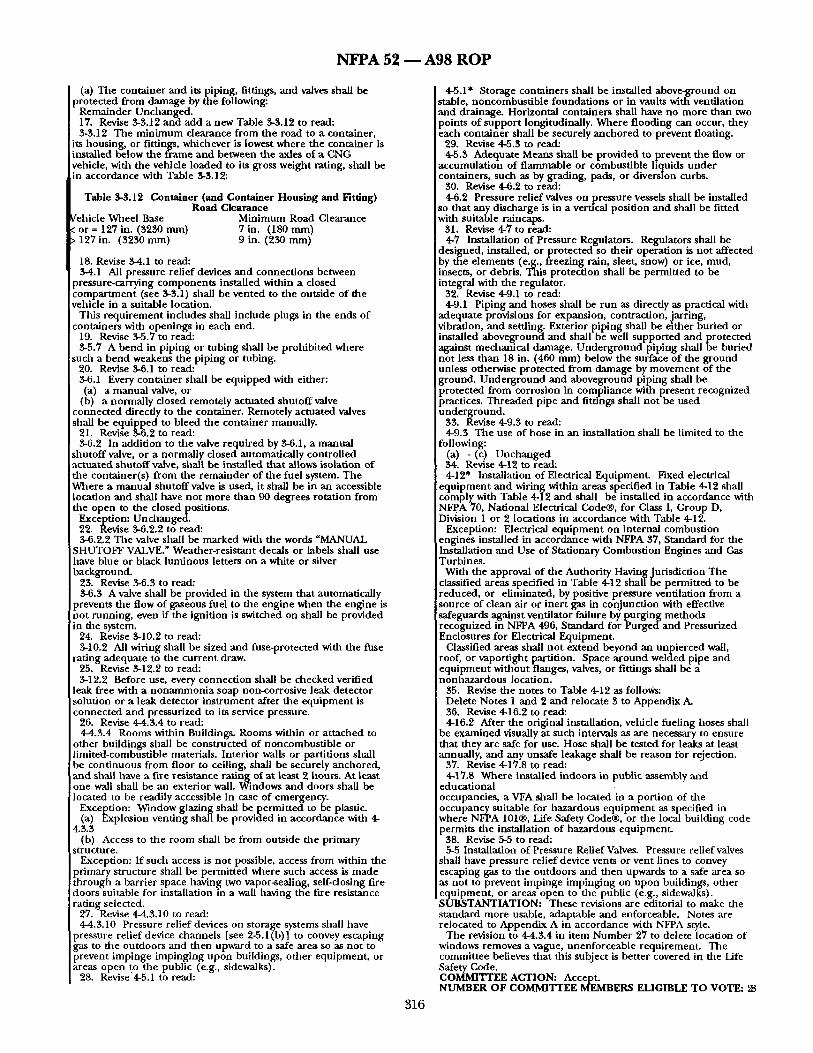
its housing, or fittings, whichever is lowest where the container is installed below the f rame and between the axles of ~ CNG vehicle, with the veh lde loaded to its gross weight rating, shall be in accordance with Table 3-3.12:
Table 3-$.12 Container (and Container Housing and Fitting) Road Clearance
Vehicle Wheel Base Minimum Road Clearance ~. or = 127 in. (3230 mm) 7 in. (180 mm) > 197 in. (3230 mm) 9 in. (230 mm)
18. Revise 3-4.1 to read: 3-4.1 All pressure relief devices and connect ions between
pressure-carrying componen t s installed within a dosed compar tment (see 3-3.1) shall be vented to the outside of the vehicle in a suitable location.
This r equ i rement i ndudes shall include plugs in the ends of containers with openings in each end.
19. Revise 3-5.7 to read: 3-5.7 A bend in piping or tubing shall be prohibi ted where
such a bend weakens the piping or tubing• 20. Revise 3-6.1 to read: 3-6.1 Every container shall be equipped with either: (a) a manual valve, or
(b) a normally closed remotely actuated shutoff valve connected directly to the container. Remotely actuated valves shall be equipped to b leed the container manually.
21 • Revise 3-6.2 to read: 3-6.2 In addit ion to the valve required by 3-6.1, a manual
shutoff valve, or a normally d o s e d automatically control led actuated shutoff valve, shall be installed that allows isolation of the container(s) f rom the remainder of the fuel system. The Where a manual shutoff valve is used, it shall be in an accessible location and shall have no t more tban 90 degrees rotat ion from the open to the c losedposi t ions .
Exception: Unchanged. 22. Revise 3-6.2.2 to read: 3-6.2.2 The valve shall be marked with the words "MANUAL
SHUTOFF VALVE." Weather-resistant decals or labels shall use have blue or black luminous letters on a white or silver background.
23. Revise 3-6.3 to read: 3-6.3 A valve shall be provided in the system that automatically
prevents the flow of gaseous fuel to the engine when the engine is no t running, even if the ignition is switched on shall be provided in the system.
24. Revise 3-10.2 to read: 3-10.2 All wiring shall be sized and fuse-protected with the fuse
rating adequate to the current draw. 25. Revise 3-12.2 to read: 3-12.2 Before use, every connect ion shall be checked verified
leak free with a nonammonia soap non-corrosive leak de tec tor solution or a leak detector ins t rument after the equipment is connec ted and pressurized to its service pressure.
26. Revise 4-4.3.4 to read: 4-4.3.4 Rooms within Buildings. Rooms within or a t tached to
other buildings shall be constructed of noncombust ib le or l imited-combustible materials. Interior walls or partit ions shall be cont inuous from floor to ceiling, shall be securely anchored, and shall have a fire resistance rating of at least 2 hours. At least one wall shall be an exterior wall. Windows and doors shall be located to be readily accessible in case of emergency.
Exception: Window glazing shall be permi t ted to be plastic. (a) Explosion venting shall be provided in accordance with 4- .3.3 (b) Access to the room shall be from outside the primary
structure. Exception: If such access is no t possible, access from within the
primary structure shall be permit ted where such access is made through a barrier space having two vapor-sealing, self-closing fire doors suitable for installation in a wall having the fire resistance rating selected.
27. Revise 4-4.3.10 to read: 4-4.3.10 Pressure relief devices on storage systems shall have
pressure relief device channels [see 2-5.1(b)] to convey escaping gas to the outdoors and then upward to a safe area so as no t to prevent impinge impinging upon buildings, o ther equipment , or areas open to the public (e.g., sidewalks).
28. Revise'4-5.1 to read:
4-5.1" Storage containers shall be installed above-ground on stable, noncombust ib le foundat ions or in vaults with ventilation and drainage. Horizontal containers shall have no more than two points o f suppor t longitudinally. Where f looding can occur, they each container shall be securely anchored to prevent floating.
29. Revise 4-5.3 to read: 4-5.S Adequate Means shall be provided to prevent the flow or
accumulat ion of f lammable or combustible liquids unde r containers, such as by grading, pads, or diversion curbs•
30. Revise 4-6.2 to read: 4-6.2 Pressure relief valves on pressure vessels shall be installed
so that any discharge is in a vertical posit ion and shall be fitted with suitable raincaps.
31. Revise 4-7 to read: 4-7 Installation of Pressure Regulators. Regulators shall be
designed, installed, or pro tec ted so their operat ion is no t affected by the e lements (e.g., freezing rain, sleet, snow) or ice, mud, insects, or debris. This protect ion shall be permi t ted to be integral with the regulator.
32. Revise 4-9.1 to read: 4-9.1 Piping and hoses shall be run as directly as practical with
adequate provisions for expansion, contraction, jarring, vibration, and settling. Exterior piping shall be either buried or installed aboveground and shall be well suppor ted and protected against mechanical damage. U n d e r g r o u n d piping shall be buried not less than 18 in. (460 mm) below the surface of the ground unless otherwise pro tec ted f rom damage by. movement, o f the ground. Unde rg round and aboveground p lpmg shall be protec ted from corrosion in compliance with present recognized practices. Threaded pipe and fittings shall not be used underground•
33. Revise 4-9.3 to read: 4-9.S The use of hose in an installation shall be l imited to the
following: (a) - (c) Unchanged 34. Revise 4-12 to read: 4-12" Installation of Electrical Equipment. Fixed electrical
equ ipmen t and wiring within areas specified in Table 4-12 shall comply with Table 4-12 and shall be installed in accordance with NFpA 70, National Electrical Code®, for Class I, Group D, Division 1 or 2 locations in accordance with Table 4-12.
Exception: Electrical equ ipmen t on internal combustion engines installed in accordance with NFPA 37, Standard for the Installation and Use of Stationary Combust ion Engines and Gas Turbines.
With the approval of the Authority Having Jurisdiction The classified areas specified in Table 4-12 shall be permit ted to be reduced, or eliminated, by positive pressure ventilation f rom a source of clean air or iner t gas in conjunct ion with effective safeguards against ventilator failure by purging methods r ecogn ized in NFPA 496, Standard for P u r g e d a n d Pressurized Enclosures for Electrical Equipment .
Classified areas shall n o t extend beyond an unpierced wall, roof, or vaportight partition. Space a round welded pipe and equipment without flanges, valves, or fittings shall be a nonhazardous location.
35. Revise the notes to Table 4-12 as follows: Delete Notes 1 and 2 and relocate 3 to Appendix A. 36. Revise 4-16.2 to read: 4-16.2 After the original installation, vehicle fueling hoses shall
be examined visually at such intervals as are necessary to ensure that they are safe for use. Hose shall be tested for leaks at least annually, and any unsafe leakage shall be reason for rejection.
37. Revise 4-17.8 to read: 4-17.8 Where installed indoors in public assembly and
educational occupancies, a VFA shall be located in a por t ion of the occupancy suitable for hazardous equ ipment as specified in where NFPA 101®, Life Safety Code®, or the local building code permits the installation of hazardous equipment .
38. Revise 5-5 to read: 5-5 Installation of Pressure Relief Valves. Pressure relief valves
shall have pressure relief device vents or vent lines to convey escaping gas to the outdoors and then upwards to a safe area so as not to prevent impinge impinging on upon buildings, other equipment , or areas open to the public (e.g., sidewalks). SUBSTANTIATION: These revisions are editorial to make the s tandard more usable, adaptable and enforceable. Notes are relocated to Appendix A in accordance with NFPA style.
The revision to 4-4.3.4 in item Number 27 to delete location of windows removes a vague, unenforceable requirement . The committee believes that this subject is bet ter covered in the Life Safety Code. COMMITTEE ACTION: Accept• NUMBER OF COMMITTEE MEMBERS ELIGIBLE TO VOTE: 28
3 1 6
N F P A 52 ~ A 9 8 R O P
VOTE ON COMMITTEE ACTION: AFFIRMATIVE: 23 NOT RETURNED 5 Borland, Brock, Clasen, Dunford,
Peterson COMMENT ON AFFIRMATIVE:
BOONE: The following editorial changes are recommended: 2-4.5 Delete the word "Suitable" subjective term. 2-8.4(d) Delete the word "Suitable" subjective term. 2-9.1 Delete the word "Suitable" subjective term. 2-10.2 Delete the word "Suitable" subjective term. 3-2.2 Delete the word "Suitable" subjective term. 3-3.2.2 Delete the word "Suitable" subjective term. 3-4.1 Delete the word "Suitable" subjective term defined where
outside the vehicle. 3-6.2 Delete the word in "the second sentence. 4-6.2 Delete the word "Suitable" subjective term. 4-9.1 Delete the word adequate as a subjective term.
(Log #CP10) 52- 3 - (1-5 and Chapter 6 (New)): Accept SUBMITTER: Technical Committee on Vehicular Alternative Fuel Systems R E C O M M E N D A T I O N :
1. Add the following Definitions to 1-5. Accommodation Space. Space on a marine vessel that has been
designed for living purposes. Control Space. Space on a marine vessel in which the vessel's
radio, the main navigation equipment, or the emergency source of power is located or in which the fire control equipment, other than fire-fighting control equipment, is centralized.
Engine Compartment. An engine space on a marine vessel tha t is too small for an individual to enter.
Engine Room. An engine space on a marine vessel tha t is large enough for an individual to enter.
Gas-Dangerous Space. An enclosed or semienclosed space on a marine vessel in which there is piping containing compressed natura), gas, or where fuel containers or the engine room or compartment is located.
Gas-Safe Space. /~Jay space on a marine vessel that is not a gas-dangerous space.
Service Space. Space on a marine vessel outside the cargo area tha t is used for a galley, a pantry containing cooking appliances, lockers or storerooms, workshops (except those workshops located in machinery spaces), and similar spaces and other similar spaces and access t runk to those spaces.
Tank Compartment. A space on a marine vessel dedicated for fuel tanks tha t is too small for an individual to enter.
Tank Room. A space on a marine vessel dedicated for fuel tanks that is large enough for an individual to enter.
Vehicle. A device or structure for t ransport ing persons or things; a conveyance (e.g., automobiles, trucks, marine vessels, railroad trains, and so forth).
Weather Deck. A dec.k that is always exposed to weather on a marine vessel.
2. Add a new Chapter 6, Commercial Marine Vessels and Pleasure Craft.
Chapter 6 - Commercial Marine Vessels and Pleasure Craft The current Chapter" 6 entitled "Reference Publications" now becomes Chapter 7. 6-1 Scope. This chapter shall apply to all commercial marine vessels mad pleasure craft operating on compressed natural gas (CNG), including n.ew and retrofit construction. 6-2 Modifications to NFPA 52, Standard for Compressed Natural Gas (CNG) Vehicular Fuel System. 6-2.1 Chapters 1, 2, 4, and 5 of this standard shall all apply to commercial marine vessels and pleasure craft operating on compressed natural gas with tile exception of the paragraphs 4- 14.5, 4-14.6, and 4-1.1.10. 6-2.2 The following paragraphs from Chapter 3 of this standard shall apply to commercial marine vessels and pleasure craft operating on compressed natural gas: 3-4.1, 3-4.2, 3-4.4, 3-4.5, 3- 5.1 through 3-5.8, 3-6.1 through 3-6.5, 3-7.3, 3-8.1 through 3-8.3, 3- 9.1, 3-9.2, 3-10.1, 3-13.2, 3-11.1, 3-12.1 through 3-12.6, and 3-13.1 through 3-13.4. 6-2.3 The following paragraphs shall apply only to commercial marine vessels and pleasure craft operating on compressed natural gas. 6-2.3.1 Installation of Fuel Supply Containers.
317
6-2.3.1.1 Fuel supply containers on marine vessels shall be permitted to be located on the weather deck above accommodation and service space or below deck adjacent to accommodation and service space,provided all connections to d~e containers are external to or sealed and vented from these spaces.
Containers on the weather deck shall be protected with a housing to prevent damage that can occur due to loading, unloading, direct sunlight, and the general use of the vessel. The housing shaU be installed in such a way that contact of the housing with the container and entrapment of materials that could damage the container or its coating is prevented. The shelter for storing the containers on the weather deck shall be an enclosure constructed of noncombustible or limited-combustible materials that has at least one side predominantly open , facing outboard, and a roof designed for ventilation and dispersal of escaped gas. 6-2.3.1.2 Each fuel supply container shall be mounted in a location to minimize damage from collision. No part of a container or its appurtenances on the weather deck shall protrude beyond the sides or top of the vessel at the point where it is installed. 6-2.3.1.3 No portion of a fuel supply container or container appurtenances shall protrude beyond the bow or the stem of the vessel. Container valves shall be protected from physical damage using the vessel structure, valve protectors, or a suitable metal shield. 6-2.3.1.4 Each container rack shall be secured to the vessel frame, either above or below or both, using a method capable of withstanding a static force in the six principal directions to prevent damage from slippage, loosening, or rotation directions (see Figure 3-3.3) of four times the weight of the fully pressurized container. 6-2.3.1.5 Each fuel supply container in the rack shall be secured to its cradle in such a manner that it is capable of withstandinga static force applied in the six principal directions (see Figure 3- 3.3) of four times the weight of the fully pressurized container with a maximum displacement of .5 in. (13 mm). 6-2.3.1.6 The container weight shall not be supported by outlet valves, manifolds, or other fuel connections. 6-2.3.1.7 Fuel supply containers located less than 8 in. (200 mm) from the exhaust system shall be shielded against direct hea l 5-2.3.1.8 The mounting system shall minimlz" e fretting corrosion between the container and the mounting system. 6-2.3.1.9 Fuel supply containers shall not be installed so as to adversely affect the balance of the marine vessel. 6-2.3.1.10 Metal clamping bands and their supports shall not be in direct contact with a container. A resilient gasket that does not retain water shall be installed between the clamping bands and their supports and a container.
6-2.3.1.11 A container, where located in a below-deck tank room or tank compartment that is capable of accumulating natural gas, shall be installed so that the pressure relief device for the protection of the container is installed in the same space as the container and the discharge from the pressure relief device meets dm following requirements:
(a) It is vented to the outside through a metallic tube (vent mast) or hose no smaller than the outlet diameter of the relief device, secured at 12 in. (300 mm) intervals wbere the tube exceeds 24 in. (610 mm) in length and has a minimum burst pressure of at least 1.5 times the service pressure of the container at 400iF (204iC).
(b) It is located so that the vent opening is not blocked by debris or otherwise affected by the elements. 6-2.3.2 Installation of Pressure Gauges. 6-2.3.2.1 A pressure gauge located within the wheelhouse (bridge) or accommodation or service space shall be installed in such a manner that no gas flows through the gauge in the event of failure. 6-2.3.2.2 A pressure gauge installed in the engine compartment, fuel container compartment, or other gas-dangerous space shall be equipped with a limiting orifice, a shatter-proof dial lens, and a body relief. 6-2.3.3 Labeling. Each marine vessel or pleasure craft shall be identified with weather- resistant, dianlond-shaped labels located on an exterior vertical surface or near-vertical surface, at a location, as near to eye level as possible, where the vessel is routinely boarded, both port and starboard. Depending on the size of the vessel, other labels should be placed at logical locations to alert persons not familiar widl the vessel, such as fire fighters or service personnel, as to the nature of the vessel. The label shall be a minimum of 4 3/4 in. (120 ram) long by 3 3/4 in. (83 ram) high. The marking shall consist of a border with the
N F P A 52 - - A 9 8 R O P
letters CNG, a m i n i m m n of 1 in. (25 mm) high, shown in silver or white reflective hnn i nous material on a blue background. 6-2.3.4 Opera t ion. 6-2.3.4.1 Where CNG is being t ransferred to or f rom a mar ine vessel, the engines shall be t u rned off. Exception: It shall be permi t ted to operate the engine when it is necessary to ho ld the vessel in posit ion while refileling or when, in the opin ion of the master , the safety of the vessel is at issue. The master shall also be permi t ted to elect to opera te genera tors dur ing refileling. 6-2.3.4.2 A warning sign with the words "Stop Engines," "No Smoking," "Flammable Gas" shall be pos ted at d i spens ing stations and compressor areas where it is possible to secure a vessel to a dock or ancho r buoys. Otherwise, a sign shall be
OSted with file words "No Smoking," "Flammable Gas". The cation of signs shall be de te rnf ined by local condit ions, bu t the
let tering shall be large e n o u g h to be visible and legible f r om each point o f transfer. 6-3 Fire Protection for Vessels. 6-3.1 Fire protect ion for vessels shall be in accordance widl NFPA 302, Fire Protect ion S tandard for Pleasure and Commercia l Motorcraft. T he following paragraphs of NFPA 302 shall be revised as follows when used for CNG filel systems. 6-3.1.1 2-5.3.4(b) shall be rewrit ten as follows: Located in the uppe r one- thi rd of the co rupar tmen t 6-3.1.2 4-1.1 Exception shall be rewritten as follows: Engine- cooling water or exhaus t cooling water. 6-3.2 NFPA 52 shall have precedence over s tandards in NFPA 302 ,as they relate to the use of compressed natural gas. 6-4 Fire Protect ion for Marinas a n d Boatyards. 6-4.1 Fire protect ion for mar inas a n d boatyards shall be in accordance with NFPA 303, Fire Protect ion S tandard Marinas and Boatyards. The following paragraphs of NFPA 303 shall be revised as follows when used for CNG filel systems. 6-4.1.1 6-3.2 sball be rewrit ten as follows: All boat fileling opera t ions shall be carefiflly accompl i shed in accordance with NFPA 302, Fire Protection Standard for Pleasure and Commercial Motor Craft, and NFPA 52, Standard for Compressed Natural Gas ((~G) Vehicular Fuel Systems, at the fileling station. 6-4.1.2 6-3.4 shall be rewritten as follows: Fuel storage tanks shall be installed in accordance with NFPA 30A, Automotive and Marine Service Station Code, and NFPA 52, Standard for Compressed Natural Gas (CNG) Vehicular Fuel Systems, ,'rod in accordance with all state and local ordinances . 6-4.1.3 The first sen tence of 6-3.9 shall be rewritten as follows: Dispensing units for t ransferr ing filel f rom storage tanks shall be in accordance with the provisions of NFPA 30A, Automotive and Marine Service Station Code. and NFPA 52, Standard for Compressed Natural Gas (CNG) Vehicular Fuel Systems. (The rest of the pa ragraph is unmodi f ied . ) 6-5 Fuel Dispensing. 6-5.1 CNG dispens ing shall be in accordance with NFPA 30A: Automotive a n d Marine Service Station ( 'ode. Section 3-1 of NFPA 30A shall be revised as follows:
Compressed natural gas_powered mar ine vessels, shall be in accordance with NFPA 30A, Automotive and Marine &write Station Code, shall apply with the following addi t ion to Section 3-1, General. The design, fabrication, assembly, test, and inspect ion of the piping system shall be in accordance with NFPA 30, Flammable and Combustible Liquids Cod~ Chapter 3, and NFPA 52, Standard for Compressed Natural Gas (CNG) Vehicular Fuel Systems. 6-6 Engine Rooms or Engine Compar tments . 6-6.1 Location off i le l lines in engine rooms and engine compar tments . All fi~el lines shall be m o u n t e d nea r file ceiling in order to provide the shor tes t route for leaking gas to flow to the exterior. 6-6.2 Fuel Line Pressure. The pressure in the filel lines passing t h rough the eng ine room or engine c o m p a r t m e n t shall no t exceed die pressure requi red to operate the engines. 6-6.3 Pressure Regadators. All pressure regulators, except those m o u n t e d on the engine(s) , shall be located in the tank room or comt)ar tment . 6-6.4 Ventilation. 6-6.4.1 Engine rooms or compar tmen t s shall be provided with positive pressure and passive ventilation. Positive pressure ventilation shall provide a n t i n i mum of 30 volumetr ic exchanges per hour . 6-6.4.2 T h e ventilation system shall be capable of hand l ing a combust ib le mixture , if necessary. T he ventilation fans shall take air f rom the weather deck and discharge it back to the weather deck t h r o u g h ducts that shall have a m a x i m u m separat ion f rom the fans. Multiple discharge ducts shall be used if practical to e n h a n c e ventilation. 6-6.4.3 If eng ine combns t ion ,air is taken f rom the engine room or engine compar tmen t , the 30 air exchanges per hou r shall be in
excess of the m a x i m u m air vo lume per hou r requi red by the e n ~ n e s . 6-6.5 Engines. 6-6.5.1 Since compressed natural gas engines have a natural gas a tmosphe re in the crankcase, they shall be provided with blowout plugs to relieve p res su re in the event of a crankcase explosion. Blowout plugs shall be located so as to limit risk to the crew. 6-6.5.2 Engines shall be permi t ted to be located on the weather deck. 6-6.5.3 Engines located on the weather deck shall be protected with a hous ing to p reven t damage tha t can occur due to loading, unloading , or the general use o f the vessel. 6-6.5.4 A shel ter for an eng ine installed on the weather deck shall be an enclosure cons t ruc ted of noncombus t ib l e or limited- combust ib le materials tha t has at least one side p redominant ly open, facing outboard, and a roof des igned for dispersal of escaped gas. 6-6.5.5 An engine or engines on the weather deck sball be m o u n t e d in a location tha t would ensure m i n i m u m d am ag e f rom collision. No part of an eng ine or its appu r t enance s shall ) ro t rude beyond the sides or top of the vessel at the poin t where it is installed. 6-6.5.6 No port ion of an eng ine on the weather deck shall p ro t rude beyond the bow or s tern of the vessel. 6-6.6 Natural Gas Monitor ing. 6-6.6.1 Engine Rooms. 6-6.6.1.1 Engine rooms shall have at least two natural gas
d e t e c t o r s placed in the overhead at the fore and aft locations. 6-6.6.1.2 Moni tor ing stations shall be located in the engine room, in the whee lhouse (bridge), a n d in an accommoda t ion or service space, such as a galley, where crew m e m b e r s are likely to congregate. 6-6.6.1.3 W h e n no gas is detected, the moni to r ing stations shall show a g reen light. 6-6.6.1.4 At one- ten th of the lower f lammable level (LFL) of the concentra t ion, power venti lat ion shall activate s imul taneously with a f lashing yellow light accompan ied by a klaxon at each mon i to r ing station. 6-6.6.1.5 When the mon i to r ing system detects a concent ra t ion that is one-fifth of the LFL, a f lashing red light accompan ied by a siren shall activate at each mon i to r ing station. W h e n the one-fifth LFL is detected and the alarm system activated, an emergency fuel shutof f shall be activated s imultaneously, which will t e rminate the flow of fuel to the engine room. 6-6.6.1.6 A manua l override switch shall be m o u n t e d in the engine room so that the crew can tu rn off the alarm an d restore fuel to the engines in the event of a false alarm or o ther contingency. 6-6.6.1.7 W h e n the compressed natural gas fllel supply is shu t clown due to loss of ventilation or detect ion of gas, the master shall ensure tha t the compressed natural gas filel supply is no t nsed until the leak or o ther cause of the shu tdown is f o u n d and corrected. 6-6.6.2 Engine Compar tmen t s . Eng ine compa r tme n t s shall be equ ipped with natural gas detect ion a n d shu tof f system as requi red for engine rooms, except that a mon i to r ing station shall be placed only at the wheelhouse (bridge). If the vessel is large enough; however, and the a larm canno t be heard if no one is m a n n i n g the whee lhouse (bridge), t hen the e q u i p m e n t shall also be placed in a c c o m m o d a t i o n or service space. 6-6.7 Fire Equ ipmen t and Systems. 6-6.7.1 Compressed natural gas_powered mar ine vessels of all sizes shall carry fire e q u i p m e n t and systems tha t are required by IJ.S. Coast Guard. 6-6.7.2 In addit ion, eng ine rooms and engine compar tmen t s shall have a 150iF (66iC) thermal switch tha t shaU activate fire- f ight ing equ ipment . W h e n file thermal switch is activated, a f lashing red light and an audible alarm sball activate in the engine room whee lhouse (bridge) a n d o ther a ccomm o d a t i o n space or service space where crew are likely to congregate, such as a galley, s ignal ing the possible presence of a tire. 6-6.7.3 There shall be a one-miml te t ime delay, after wltich the eng ine room or c o m p a r t m e n t shall be f looded with USCG approved inert gas for two minutes . Simultaneously, file ventilation fans shall be cut off for two minu tes and then reactivated. Sufficient CO 2 shall be provided for two cycles.
6-6.7.4 A manua l override switch shall be provided in the engine room or near the engine c o m p a r t m e n t to allow terminat ion of the response in the event o f false a larm or o ther contingency. 6-6.7.5 Controls shall be provided to allow manua l activation of the CO 2 system without a delay.
6-7 Tank Rooms or Compar tmen t s . 6-7.1 Tank rooms and tank compar tmen t s shall be airtight as well as watert ight with appropr ia te fittings used to seal
3 1 8
N F P A 52 ~ A 9 8 R O P
penetrations darongh the bulkheads for wire or pipes passing through the t,'mk rooms. 6-7.2 The tank rooms shall be provided with positive pressure and passive ventilation. 6-7.3 Ventilation ot the tank rooms (comparunents) shall be provided at thirty exchanges per hour minimum. 6-7.4 Air shall be taken f rom the weather deck and discharged back to the weadler deck darough ducts that have a maximum separation from the fans. 6-7.5 The fans shall be capable of handling a combustible mixture, if necessar¢. 6-7.6 Multiple discharge ducts shall be used if practical to enhance ventilation 6-7.7 Natural Gas Monitoring. 6-7.7.1 Tank rooms or compartments shall have at least two
i namral gas sensors placed at or near the ceiling at fore and aft locations. 6-7.7.2 When no gz-s is detected, the monitoring stations shall show a green light. 6-7.7.3 Two levels of :darm shall be used for signaling the need for intervention. 6-7.7.4 An alarm shall activate when one-tenth of dae LFL is detected by a monitor. A flashing yellow light and a klaxon shall be activated in the engine room and in tile wheelhouse (bridge), as well as in an accommodat ion or service space (such as a galley) where crew are likely to congregate. Simultaneously, power ventilation shall activate. On vessels with a tank compartment , a flashing yellow light and an audible signal shall activate in the wheelhouse (bridge). ff tile vessel is large enough dlat dae alarm cannot be heard if no one is manning the wheelhouse (bridge), a second warning station shall activate in ,'m accommodation or service space where crew are likely to congregate. 6-7.7.5 At one-fifdl of LFL, a second alarm shall activate utilizing a flaslting red light and a siren. These monitor ing stations shall he placed in the same locations as tile monitoring stations for file one-tendl LFL. When dae one-fifdl LFL warning is activated, an antomatic fuel shutoff valve will terminate flow of natnral gas from tl~e tank room or compartment , ventilation shaU terminate, USCG approved inert gas shall flood file tank room, and a water deluge system shall be activated. 6-7.7.6 A tank compar tment shall not be permitted to have a deluge system if a vessel is too small to accommodate die equipment. The judgemen t will be made by dae aufllority having jurisdiction. 6-7.7.7 When dae compressed natural gas filel supply is shut down due to loss ot ventilation or detection of gas, the master shall ensure that the compressed natural gas fuel supply is not used until the leak or oilier cause of file shutdown is found and corrected. 6-7.8 Tmlk rooms and compartments shall have manual drains that remove dae waler produced by die deluge system. 6-7.9 A labeled override switch shall be available in a readily accessible location ro turn off die tank room or compar tment warning system in tile event of a false alarm or other contingency and to shut down the USCG approved inert gas and dehlge system. 6-7.10 Fire-Fighting Equipment. 6-7.10.1 Tank rooms and compartments shall have a 150iF (66iC) daermal switch that will activate at, tomatic fire-figiating eqnipment. 6-7.10.2 When tile switch is activated, a red flashing light and an audible alarm shall activate on a fire alarm panel in the wheelhouse (bridge) and in an accommodation or service space (such as a galley) inhere crew are likely to congregate. 6-7.10.3 Since dae ,~'mk rooms or compartments are u nmanne d spaces, alarms shall not be required in Oaose spaces. 6-7.10.4 Ventilation in dae tank rooms or compartments shall be terminated simultaneously wida die activation of the fire alarm. One minute after the fire alarm is activated, the tank room or compar tment shall be flooded wida USCG approved inert gas,
a n d a de uge system shall activate to keep the compressed natural gas cylinders cool and to assist in terminating fire. 6-7.10.5 The tank , ' tom or compar tment shall be provided with a readily accessible ocerride switch that will allow the crew to terminate the fire-fighting system in the event of a false alarm or other contingency. 6-7.10.6 A deluge .'.ystem shall be permitted to be omitted from tank compartments on vessels that are too small to accommodate them. This determination shall be made by the audlority having jurisdiction. 6-7.11 Lighting. 6-7.11.1 Tank rooms shall have at least two explosion-proof lighting fixtures.
6-7.11.2 Switches and overcurrent protective devices for lighting in die tank room(s) shall be in a gas-safe space. 6-8 Vent Masts. 6-8.1 All crankcases on natural gas_powered engines shall be vented to a vent mast. Vessels having more tilth one engine shall be permitted to utilize a manifold. 6-8.2 Relief valves or common vent headers from relief valves
i shall discharge to a vent mast. 6-8.3 Vent masts shall meet the following requirements:
(a) Discharge vertically upward (b) Have a rain cap or taller means of preventing tile entrance
of rain or snow (c) Extend to at le,~st a height of 10 ft (3 m) above the highest
working levet on the vessel 6-8.4 Relief valve vent masts and engine ventilation vent masts shall not be connected, hut shall be permitted to terminate at the same location. 6-9 Deluge Systems. 6-9.1 Each deluge system that protects more thma one area shall have at least one isolation valve at each branch connection and at least one isolation valve downstream from each branch connection to isolate damaged sections. 6-9.2 Each valved cross-connection from the deluge system to the fire main shall be located outside of file tank room or compartment . 6-9.3 Each pipe, fitting, and valve for tile deluge system shall be made of fire-resistant and corrosion-resistant materials such as galvanized steel or galvanized iron pipe. 6-9.4 Each deluge system shall have a means of drainage in order to prevent corrosion of the system and freezing of dae accumulated water in subfreezing temperatures. 6-9.5 Each deluge system shall have a dirt strainer dlat is located at tile deluge system manifold or pump. 6-9.6 Water to the deluge system shall be supplied by a pump that is only for the use of dae system. 6-10 Alarm Systems. 6-10.1 The gas detection alarm systems shall have a means of indicating which natural gas sensor has been activated. 6-10.2 The fire alarm systems shall have a means of indicating which thermal switch has been activated. 6-10.3 Each audible alarm shall be arranged so that is can be turned off after sounding. For a remote group alarm, dais ar rangement shall not interrupt the alarmOs actuation by taller fanlts. 6-10.4 Each visual alarm shall be one that can be turned off only ,after the fanlt dmt actuated it is corrected. 6-10.5 Each vessel shall have means for testing each alarm. 6-10.6 Gas safe spaces adjacent to gas dangerous spaces, such as engine rooms and tank compartments, shall have positive pressure ventilation systems capal~le of 30 exchanges ,an hour. Their ventilation shall activate whenever ,an alarm is activated. 6-11 Safety Equipment. 6-11.1 Marine vessels with tank rooms and engine rooms shall have:
(a) Three self-contained, pressure-demand-type, air-breathing apparatus approved by file Mining Enforcement and S,'ffety Administration (MESA) or the National Institute for Occupational Safety and Health (NIOSH), each having at least a 30-minute capacity
(b) Three spare bottles of air for the self-contained air breathing apparatus, each having at least a 30-minute capacity
(c) Three explosionproof flashlights (d) Three helmets that meet file safety requirements for
industrial head protection, ANSI Z-89.1 (e) Three sets of goggles that meet tile specification ANSI Z-
87.1, Occupational and Educational Eye and Face Protection (f) An air compressor to recharge the bottles for the air-
breadfing apparatus (g) Portable hand-laeld natural gas detectors which shall be
provided to aid in evaluating alarms and for making a survey of the vessel. These instruments shall allow locating specific leaks at very low levels of detection and shall be carried by personnel working in a compar tment containing gas storage or transmission equipment. A vessel with a tank room shall have at least two of these sensors 6-11.2 Vessels having engine rooms and tank rooms shall have a portable analyzer dlat measures oxygen levels in an inert atmosphere. 6-11.3 Before allowing anyone to enter a space that has had a gas leak dlat has been repaired, the master shall ensure that the space has an oxygen concentration of at least 19.5 percent oxygen by volume and is free of natural gas. 6-11.4 The master shall ensure that tile compressed air breadfing-equipment is inspected at least once a monda by
319
N F P A 52 1 A 9 8 R O P
licensed officer and that tile date of inspection and condition of die equipment is placed in the vesselOs log. 6-12 Safety Training. 6-12.1 A written safety guide for tile vessel and for tile safety equipment and procedures shall be provided. Tile manual shall outline all s',ffety systems and equipment and their operation. 6-12.2 Crews shall be trained to operate the compressed natural gas powered vessel and to perform repairs. 6-12.3 Training drills silallbe conducted monddy. References:
NAPA 303, Fire Protection Standard for Marinas and Boatyards, 1995 edition.
NAPA 30A, Automotive and Marine Service Station Code, 1996 edition.
NAPA 302, Fire Protection Standard for Pleasure and Commercial Motor Craft, 1994 edition.
46 CFR, Chapter 1, Part 154, Safety Standards for Self-Propelled Vessels Carrying Bulk Liquefied Gases, October 1991 edition.
ANSI Z-89.1, 1969 ANSI Z-87.1, Occupational and Educational Eye and Face
Protection, 1979. SUBSTANTIATION: A new chapter is proposed to cover CNG engine fuel systems on commercial vessels and pleasure craft. The text is based on requirements for GNG engine fuel systems for antomobiles, trucks and buses, NFPA 302, NFPA 303 and U.S. Coast Guard regulations (46 CFR Part 154).
The committee has been made aware of several demonstration projects in the U.S. and elsewhere where CNG has been successfully itsed as a vessel fuel. It believes that standards for dfis application are needed at this time.
In preparing dais new chapter of NFPA 52, die previous five chapters in NAPA 52 were utilized to file fullest extent possible by noting the paragraphs that were not applicable to marine vessels and by modifying some paragraphs to make t ram applicable. The remaining paragr.aphs are aap. plicable, as alley, are written. This was done to simplify the utilizataon of dns standard for file prospective user.
After comments concerning the existing standards were made, die remainder of die proposed chapter was organized following tile organization of die recent hazards analysis meeting in March, conducted by US Coast Guard. At daat meeting die workshol? groups were organized into Engine Rooms, Fuel Storage, Piping, and Human Effects. Following the US Guard format, Chapter 6 was broken down in part into Engine Rooms or Compartments and Tank Rooms or Compartments. This was done to cover all contingencies concerning engine spaces and tirol storage spaces.
NAPA 302, Fire Protection Standard for Pleasure and Commercial Motor Craft, is restricted to vessels of 300 tons or less. The proposed Chapter 6 attempts to cover all marine vessels because tile practicality of using compressed natural gas diminishes as larger vessels are considered becattse of weight, range, and space for fi~el container restrictions. Where engines and fliel containers are placed below deck, small vessels, such as pleasure craft, will generally have engine compartments and tank compartments. Large vessels are more likely to have engine rooms and tank rooms. (see definitions)
Since there is generally a great deal of concern about placing engines and tirol containers below deck, considerable effort was made to utilize tim standards from 46 CFR Chapter 1 Part 154, Safety Standards for Self-Propelled Vessels Carrying Bulk Liquefied Cases, because dfis is tile only current standard daat addresses itself directly to dm safety concerns surrounding natural gas eidaer as a cargo or ,as an engine fi,el.
Throughout d~e proposed Chapter 6 exerpts and adaptations from 46 CFR Chapter 1 Part 154 are utilized extensively to
~ roduce a set of practical standards that will provide for an ltrinsically safe marine vessel.
COMMITTEE ACTION: Accept. NUMBER OF COMMITTEE MEMBERS ELIGIBLE TO VOTE: 28 VOTE ON COMMITTEE ACTION:
AFFIRMATIVE: 23 NOT RETURNED: 5 Borland, Brock, Clasen, Dunford,
Peterson COMMENT ON AFFIRMATIVE:
BO()NE: The following additional changes are recommended: 6-2.3.1.3 Delete the word "Suitable" snbjective term. 6-(i.6. l.l Change "shall have at to a miuimum". 6-6.7.1 Include the U.S. Coast Guard requirements for fire
protection. 6-7.5 Change shall be capable to a fix percenutge as used
elsewhere in dm standard. 6-7.7.6 Why limit die standard to tile use of carbon monoxide
only there are other fire agent which could be used. 6-7.7.4 Change klaxon to alarm, tiffs is a more recognized term.
6-7.11.1 Change "shall have at to a minimum". The standard should be consistent use containers or cylinders.
(Log #59) 52- 4 - (1-5 Capacity): Accept SUBMITTEl~ John B. Dimmick, Pressed Steel Tank Co., Inc. R E C O M M E N D A T I O N :
Revise text as follows: Capacity - The water volume of a container in gal (L).
SUBSTANTIATION: Container water volume is required on die 3-11.1(a) label in gallons, not cu. ft as die present definition is worded. COMMITTEE ACTION: Accept. NUMBER OF COMMITTEE MEMBERS ELIGIBLE TO VOTE: 28 VOTE ON COMMITTEE ACTION:
AFFIRMATIVE: 23 NOT RETURNED: 5 Borland, Brock, Clasen, Dunford,
Peterson
(Log #CPS) 52- 5 - (1-5 Maximum Allowable Operating Pressure): Accept SUBMITI'ER: Technical Committee on Vehicular Alternative Fuel Systems R E C O M M E N D A T I O N :
Delete file definition of Maximum Allowable Operating Pressure. SUBSTANTIATION: The term is not used in die standard. COMMITTEE ACTION: Accept. NUMBER OF COMMITTEE MEMBERS ELIGIBLE TO VOTE: 28 VOTE ON COMMITTEE ACTION:
AFFIRMATIVE: 22 NEGATIVE: 1 NOT RETURNED: 5 Boriand, Brock, Glasen, Dunford,
Peterson EXPLANATION OF NEGATIVE:
DIMMICK: This is a standard for a Compressed Natural Gas system. There remains a strong concern about the compliance of equipment operators widl file pressure limits. MAOP is a clear way to communicate file maximum allowable working pressure in die system regardless of dm complications of temperature compensation. The standard should define dais pressure unambiguously, especially since overpressurizadon is a prime suspected contributing cause to at least two container failures.
(Log #58) 52- 6 - (1-5 Maximum Allowable Operating Pressure (MAOP)): ~ B ect
MITTER: John B. Dimmick, Pressed Steel Tank Co., Inc. R E C O M M E N D A T I O N : Revise text as follows: Maximum allowable Operating Pressure (l~zAOP). The
maximum pressure at which a container is allowed to operate. For cylinders the MAOP is 125 percent of the marked pressure. For pressure vessels, the MAOP is the marked design pressures , SUBSTANTIATION: MAOP should be definitively specified, not derived from a vague relationship of temperature and pressure. COMMITTEE ACTION: Reject. COMMITTEE STATEMENT: Refer to Committee Proposal 52-5 (Log #CP5). NUMBER OF COMMITTEE MEMBERS ELIGIBLE TO VOTE: 28 VOTE ON COMMITTEE ACTION:
AFFIRMATIVE: 22 NEGATIVE: 1 NOT RETURNED: 5 Borland, Brock, Clasen, Dunford,
Peterson EXPLANATION OF NEGATIVE:
DIMMIGK: See my Explanation of Negative on Proposal 52-5 (Log #CP5). COMMENT ON AFFIRMATIVE:
PETSINGERz This should be in NFPA 52 as it is not understood by GNG designers and users.
320
N F P A 52 ~ A 9 8 R O P
(LOg #64) 52- 7 - (1-5 Pressure Relief Device): Accept SUBMrlWER: William E. Liss/Alissa Oppenheimer , Gas Research hast. R E C O M M E N D A T I O N :
Revise text as follows: 1-5 Definitions. Pressure Relief Device. "...pressure from rising above a predetermined maximum and
for the purpose of preventing a container or high-pressure line rupture." SUBSTANTIATION: The definition should end there. The remainder of the existing definition is more appropriately contained in tile section related to Qualifications of the devices. The definition should be more general and less application oriented. COMMITTEE ACTION: Accept. NUMBER OF COMMHWEE MEMBERS ELIGIBLE TO VOTE: 28 VOTE ON COMMITTEE ACTION:
AFFIRMATIVE: 22 NEGATIVE: 1 NOT RETURNED: 5 Borland, Brock, Clasen, Dunford,
Peterson EXPLANATION OF NEGATIVE:
DIMMICI~ The proposed definition is incorrect. PRDs are generally not designed to prevent the pressure from exceeding a predetermined maximum. Most PRDs are insensitive to pressure but activated by temperature. The sole function of a PRDis to prevent a container rupture in a fire. PRDs are not generally used to protect against line rupture in a fire. Fuel lines, whether metallic or not may rupture in an intense fire.
(Log #62) 52- 8 - (1-5 Service Pressure): Accept SUBMITTER: W'dliam E. Liss/Alissa Oppenheimer , Gas Research hast. R E C O M M E N D A T I O N :
Revise text as follows: 1-5 Definitions. Service Pressure. The nominal gas pressure at a uniform gas
temperature of 70°F (21°C) when the equipment is properly and confpletely charged with gas; the nominal design pressure for which the equipment has been constructed. SUBSTANTIATION: the term "settled" in this context is not needed or appropriate. The Service Pressure is related to the desil~gn and nominal rating of the vessel and not with any particular pressure measurement. COMMITTEE ACTION: Accept.
[ Service Pressure. The nominal gas pressure at a uniform gas [ temperature of 70°F (21°C) wilen the equipment is completely [ charged with gas; the nominal design pressure for which the [ equipment has been constructed.
COMMITTEE STATEMENT: Accepted with an editorial revision. NUMBER OF COMMITTEE MEMBERS ELIGIBLE TO VOTE: 28 VOTE ON COMMITFER ACTION:
AFFIRMATIVE: 23 NOT RETURNED: 5 Borland, Brock, Clasen, Dunford,
Peterson
(Log #63) 52- 9 - (1-5 Settled Pressure): Reject SUBMITT-EI~ William E. Liss/Alissa Oppenheimer , Gas Research Inst. R E C O M M E N D A T I O N : Revise text as follows: 1-5 Definitions. Set t led Pressure . The pressure in a container when the
uni form gas t empera tu re wi th in the container is equal to the t empera tu re of the sur rounding ambient air. SUBSTANTIATION: The settled pressure is the actual pressure reading in the container after the contents have come into thermal equilibrium with the surrounding ambient. This will occur at any temperature and is not limited to 70°F. COMMITTEE ACTION: Reject. COMMITrER STATEMENT: The Committee believes that a
is a nec compon t of se ed pr ure OF T O
VOTE ON COMMITTEE ACTION: AFFIRMATIVE: 19 NEGATIVE: 4 NOT RETURNED: 5 Borland, Brock, Clasen, Dunford,
Peterson EXPLANATION OF NEGATIV~
ADCOCK: For Log #63 it appears that there are valid concerns with the indnsion of a temperature related to the settling pressure of a container. I would change myvote to a negative regarding the Committee Action.
BOONE: The definition provided for Settled Pressure is a correct definition and should be considered by the Committee.
MARSHALL: Submitter is correct. Current 1-5 definition is misleading and unnecessarily restrictive.
PETSINGE~ I disagree with the Committee Statement. Settled pressure can occur at any temperature.
(Log #7) 52- 10 - (1-5 Vehlde (New), 24 ) : Reject SUBMFIWER: Smart G. Tays, TQM Engineering, Inc. R E C O M M E N D A T I O N : Section 1-5, q)efinit lons", should add a definition of a "vehicle"
t h a t will include a t rac tor- t ra i ler configuration wi th a fifth wheel.
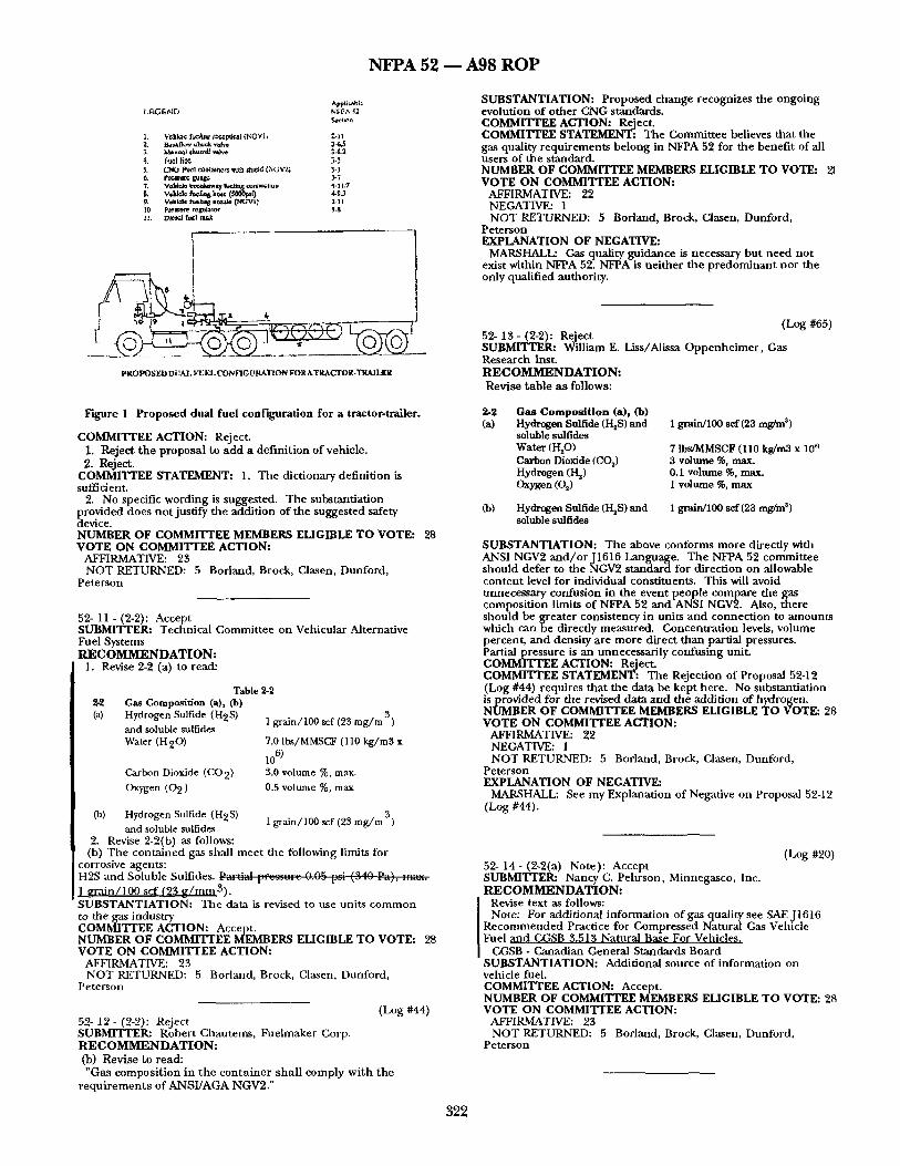
Section 2 4 , "Design and Construct ion of Containers" should add a pa ragraph to include a requ i rement to have a flow res t r ic t ing orifice in the outlet of the cylinder to minimize the flow of CNG should the re be a rup ture of a downst ream element, i.e., fueling hose, m a n u a l shutoffvalve, tube fitting, etc. SUBSTANTIATION: Long haul tractor trailers are unable to accommodate sufficient CJqG storage on the tractor to allow long distance travel between sparsely located CNG dispensing stations. By being able to install additional cylinders on the trailer, this problem would be resolved and permit the use of clean burning CNG in areas of high air pollution.
THE PROBLEM Driven by the twin public policy objectives of clean air and
reduced dependency on foreign oil, compressed natural gas is becoming the alternative fuel of choice for fleet operators. Unfortunately due to a lack of significant fueling infrastructure, the availability of CNG is limited to local fleets usually fueled at a central location. This has precluded the use of CNG for long haul fleets. Here in the Los Angeles basin, 40 percent of the NOx air pollution is generated by less than 1 percent of our vehicles - heavy duty diesel trucks including long lxaul tractor-trailersl
THE SOLUTION I am proposing a simple solution to the clmilenge of providing
sufficient on board CNG storage for Uactor-trailers that would allow them to operate safely and without the present restrictions of limited range due to the lack of fueling infrastructure. My proposal is to install the CNG fuel cylinders on the trailer, with a connecting fuel hose across the fifth wheel to the tractor engine. This concept will incorporate all the exiting safety features of NFPA 52 for vehicular fuel and dispensing systems, including breakaway devices and flow restricters common in CNG dispensing systems. These safety features will preclude any leakage of CNG should the tractor become detached from the trailer, and minimal leakage should the fuel t ramfer hose become damaged in an accident. Figure 1 shows the basic elements of d ~ e ~ s~tem.
Reducing air pollution and dependency on foreign oil are national priorities. Converting heavy duty vehicles to m n on CNG, an abundant and low cost fuel, is a win-win situation for everyone. Installing CNG storage systems on tractor-trailer trailers will provide for sufficient economic and pollution free fuel capacity to allow truckers to operate safely over long distances without having to d e p e n d o n a CNG refueling infrastructure that is not available today.
CONCLUSIONS CNG is a safe, economic, and pollution free vehicle fuel. It has
inherent qualifies that make it a more desirable fuel than gasoline or diesel, this proposal to allow for the installation of a CNG storage and delhaery system on a tractor-trailer trailer that will be as safe as the present regulations for installing CNG storage and fuel delivery system on a motor vehicle (tractor). It will also provide the fleet operator with the wherewithal operate safely, reduce operating costs, and contribute to cleaning up the air and reducing dependence on foreign oil.
321
NFPA 52 1 A98 ROP
A~l k.~l'3 t.
1. vchk~ ft~|i;~ ~ ¢ , ~ (NOVii 2-11 ~. t ~ ul~Gk vehu 34~,5 .~. M~Bu~} ehuu,f~ rove ~-6.a 4. Fuel li~ 3-5 ~. ~'~lO ~ 1 c~ntaiae~ with SlI~[d (NG~Oj 3-]
7, vohid~ tn~dmwuy fudtag ~o ~w~,~l:u ~ 4-1 !.7
P, V~hiel~ ftmlii 8 n~v.~e ~ G ~ I ~ ~-) 1 I0 p~ssur~ ~e[qllaltw 7t-8 11. DIcIcd f ~ ! cask
p R O P O S E D D i: &L. FUEL CON FIC 0 RATION FOR A T R A C T O R - T R A i I ~ R
SUBSTANTIATION: Proposed change recognizes the ongoing evolution of other CNG standards. COMMITTEE ACTION: Reject. COMMITTEE STATEMENT: The Committee believes that the gas quality requirements belong in NFPA 52 for the benefit of all users of the standard. NUMBER OF COMMITTEE MEMBERS ELIGIBLE TO VOTE: VOTE ON COMMITTEE ACTION:
AFFIRMATIVE: 22 NEGATIVE: I NOT RETURNED: 5 Borland, Brock, Clasen, Dunford,
Peterson EXPLANATION OF NEGATIVE:
MARSHALL: Gas quality guidance is necessary but need not exist within NFPA 52. NFPA is neither the predominant nor the only qualified authority.
(Log #65) 52- 13 - (2-2): Reject SUBMITTER: William E. Liss/Alissa Oppenheimer, Gas Research Inst. R E C O M M E N D A T I O N : Revise table as follows:
Figure 1 Proposed dual fuel configuration for a tractor-trailer.
COMMITTEE ACTION: Reject. 1. Reject the proposal to add a dei'mition of vehicle. 2. Reject.
COMMITTEE STATEMENT: 1. The dictionary definition is sufficient.
2. No specific wording is suggested. The substantiation provided does not justify the addition of the suggested safety device. NUMBER OF COMMITTEE MEMBERS ELIGIBLE TO VOTE: 28 VOTE ON COMMITTEE ACTION:
AFFIRMATIVE: 23 NOT RETURNED: 5 Borland, Brock, Clasen, Dunford,
Peterson
52- 11 - (2-2): Accept SUBMITTER: Technical Committee on Vehicular Alternative Fuel Systems R E C O M M E N D A T I O N :
1. Revise 2-2 (a) to read:
Table 2-2 ~2 Gas Composition (a), 0b)
Hydrogen Sulfide (H2S) and soluble sulfides Water (H20)
Carbon Dioxide (CO2) Oxygen (02 )
(b) Hydrogen Sulfide (H2S) and soluble sulfides
2. Revise 2-2(b) as follows:
1 grain/100 scf (23 mg/m 3)
7.0 Ibs/MMSCF (110 kg/m3 x
106) 3.0 volume %. max. 0.5 volume %, max
i grain/100 scf (23 mg/m 3)
(b) The contained gas shall meet the following limits for corrosive agents: H2S and Soluble Sulfides. v . r . : ~ l ~rcz~urc 0.0~ "-: /~A~ Pa), --~'" 1 grain/100 scf (~3 g /mm3) . SUBSTANTIATION: The data is revised to use units common to tile gas industry COMMITTEE ACTION: Accept. NUMBER OF COMMITTEE MEMBERS ELIGIBLE TO VOTE: 28 VOTE ON COMMITTEE ACTION:
AFFIRMATIVE: 23 NOT RETURNED: 5 Borland, Brock, Clasen, Dunford,
Peterson
(Log #44) 52- 12 - (2-2): Reject SUBMITTER: Robert Chautems, Fuelmaker Corp. R E C O M M E N D A T I O N : Co) Revise to read: "Gas composition in the container shall comply with the
requirements of ANSI/AGA NGV2."
2-2 Gas Composition (a), (lo) (a) Hydrogen Sulfide (H2S) and
soluble sulfides Water (HsO) Carbon Dioxide (CO s ) Hydrogen (I-~) Oxygen (02)
(b) Hydrogen Sulfide (HsS) and soluble sulfides
I grain/100 sef (23 mg/m 3)
7 lbs/MMSCF (110 kg/m3 x 10 ~ 3 volume %, max. 0.1 volume %, max. 1 volume %, max
1 grain/lO0 scf (23 mg/m s)
SUBSTANTIATION: The above conforms more directly with ANSI NGV2 and/or J1616 Language. The NFPA 52 committee should defer to the NGV2 standard for direction on allowable content level for individual constituents. This will avoid unnecessary confusion in the event people compare the gas composition limits of NFPA 52 and ANSI NGV2. Also, there should be greater consistency in units and connection to amounts which can be directly measured. Concentration levels, volume percent, and density are more direct than partial pressures. Partial pressure is an unnecessarily confusing unit. COMMI'[TEE ACTION: Reject. COMMITTEE STATEMENT: The Rejection of Proposal 52-12 (Log #44) requires that the data be kept here. No substantiation is provided for the revised data and tile addition of hydrogen. NUMBER OF COMMITTEE MEMBERS ELIGIBLE TO VOTE: 28 VOTE ON COMMITTEE ACTION:
AFFIRMATIVE: 22 NEGATIVE: 1 NOT RETURNED: 5 Borland, Brock, Clasen, Dunford,
Peterson EXPLANATION OF NEGATIVE:
MARSHALL: See my Explanation of Negative on Proposal 52-12 (Log #44).
(Log #20) 52- 14- (2-2(a) Note): Accept SUBMITTER: Nancy C. Pehrson, Minnegasco, Inc. R E C O M M E N D A T I O N :
Revise text as follows: Note: For additional information of gas quality see SAE J1616
Recommended Practice for Compressed Natural Gas Vehicle Fuel and CGSB 3.513 Natural Base For Vehicles.
CGSB - Canadian General Standards Board SUBSTANTIATION: Additional source of information on vehicle fiml. COMMITTEE ACTION: Accept. NUMBER OF COMMITTEE MEMBERS ELIGIBLE TO VOTE: 28 VOTE ON COMMITTEE ACTION:
AFFIRMATIVE: 23 NOT RETURNED: 5 Borland, Brock, Clasen, Dunford,
Peterson
322
N F P A 52 m A 9 8 R O P
(Log #57) 52- 15 - (2-3.1(a)): Reject SUBMITTER: J o h n B. Dimmick, Pressed Steel Tank Co., Inc. R E C O M M E N D A T I O N : Delete: P ressure relief devices, including.
SUBSTANTIATION: Pressure relief devices for gas cylinders are certified by the manufacturer to a standard but are not normally listed. This is an unnecessary requirement. COMMITTEE ACTION: Reject. COMMITTEE STATEMENT:' The UL representative on the committee has advised the committee that these devices are being listed. The current requirement also allows approval. NUMBER OF COMMrr rEE MEMBERS ELIGIBLE TO VOTE: 28 VOTE ON COMMITTEE ACTION:
AFFIRMATIVE: 22 NEGATIVE: 1 NOT RETURNED: 5 Borland, Brock, Clasen, Dunford,
Peterson EXPLANATION OF NEGATIVE:
DIMMICK: The explanation that listing, or approval ors is necessary because L Is listing PRDs is frail. If UL implied that all PRDs are listed, tlds is not true. The most widely used PRD, a CGA CC,-5 is certified by the manufacturer but bears no listing. I am not aware that a case has been made that listing or approval is required for safety.
(Log #21) 52- 16- (2-4.4): Accept SUBMITTER: Nancy CL Pehrson, Minnegasco, Inc. R E C O M M E N D A T I O N :
Delete text as follows: Cylinders shall be manufactured, inspected, marked, tested,
retested, equipped, and used in accordance with U.S. DeparUnent of Transportation (DOT) or Canada Transport (TC) Regulations, exemptions, or special permits, or ANSI/AGA NGV2, Basic Requirements for Compressed natural Gas Vehicle (NGV) Fuel Containers, specifically for CNG service. ==d r~r.2
SUBSTANTIATION: Nominal service pressure for ANSI/AGA NGV2 as given in Section 4.2 Service Pressures are 20,700 kPa (3000psi) or 24,800 kPa (3600 psi). Deletion eliminates inference that ANSI/AGA NGV2 addresses the lower pressure. COMMrITEE ACTION: Accept. NUMBER OF COMMrr rEE MEMBERS ELIGIBLE TO VOTE: 28 VOTE ON COMMITTEE ACTION:
AFFIRMATIVE: 23 NOT RETURNED: 5 Borland, Brock, Clasen, Dunford,
Peterson
(Log #34) 52- 17 - (2-4.4): Reject SUBMITFER: Norman L. Newhouse, Lincoln Composites R E C O M M E N D A T I O N : Revise text as follows: "...and shall have a rated service pressure of not less than 2~OO P=" (IS.~-----F=) ~ . i ~ J . L ? , ~ _ m ~ at 70°F (21.1°C). " SUBSTANTIATION: NGV2 has deleted reference to 2400 psi systems, cylinders for NGV now being built are ?~)00psl minimum. Lower pressure cylinders in service would be covered under a grandfather clause. COMMITTEE ACTION: Reject. COMMITTEE STATEMENT: The Committee does not see a reason to have a minimum service pressure. See Proposal 52-16 (Log #21) where the requirement was deleted. NUMBER OF COMMrlWEE MEMBERS ELIGIBLE TO VOTE: 28 VOTE ON COMMITrEE ACTION:
AFFIRMATIVE: 2-g NOT RETURNED: 5 Borland, Brock, Clasen, Dunford,
Peterson
(Log #56) 52- 18 - (2-4.4): Reject SUBMITTER: J o h n B. Dimmick, Pressed Steel Tank Co., Inc. R E C O M M E N D A T I O N : Delete: "retested" from t he first sentence.
SUBSTANTIATION: Retesting or reinspection of containers is not properly listed under design and construction. Retest or reinspection should be addressed in a separate clause as PCroposed elsewhere.
OMMITTEE ACTION: Reject. 323
COMMIIWEE STATEMENT: The Committee believes that all
~u~ r requirements be located in Chapter 2. ER OF COMMITTEE MEMBEI~ ELIGIBLE TO VOTE: 28
VOTE ON COMMITTEE ACTION: AFFIRMATIVE: 2"2 NEGATIVE: 1 NOT RETURNED: 5 Borland, Brock, Clasen, Dunford,
Peterson EXPLANATION OF NEGATIVE:
DIMMICK: The heading for 2-4 is design and construction of containers, not maintenance and inspection. Failure by users to maintain and inspect containers regularly has been implicated in at least two container failures. The user of the standard should not be expected to read the design and construction section if he is only interested in maintaining what he owns. Maintenance and inspection should be dearly located in the appropriate section, not under design. COMMENT ON AFFIRMATIVE:
DeREMER: The commentor is correct in stating that retesting or reinspection are not properly located in Section 2-4.4. Section 2-4.4 is entitled "Design a n d Construction of Containers." Retesting and reinspection occur throughout the life of the container, and are not performed only during design and manufacture.
(Log ~ ) 52- 1O - (2-4.4): Reject SUBMITTER: William E. Liss/Allssa Oppenheimer , Gas Research Inst. R E C O M M E N D A T I O N : Revise text as follows: 2-4.4 "...no specific text recommended..."
SUBSTANTIATION: The NGV container market is replete with a variety of designs and designations, including DOT 3AA, DOT RSPA, NGV2, FMVSS $04, similar Canadian as well as pending ISO identifiers. Somehow language needs to be developed which is more general and which does not act to potentially prohibit otherwise acceptable certified designs. COMMr[ ' rEE ACTION: Reject. C O ~ STATEMENT: No specific proposal is provided. The Committee notes that the standard is specific in reference to ~u~ r standards.
ER OF CoMMrrTEE MEMBERS ELIGIBLE TO VOTE: 28 VOTE ON COMMI'FIT.E ACTION:
AFFIRMATIVE: 25 NOT RETURNED: 5 Borland, Brock, Clasen, Dunford,
Peterson COMMENT ON AFFIRMATIVE:
MARSHALL: Committee actions are correct in that 2-4.4 does not die design. Submitter's in tent is also correct, but any revisions belong in base codes, not NFPA 52.
(Log #85) 52- 20 - (2-4.7): Reject SUBMFrrER: John B. Dimmick, Pressed Steel Tank Co., Inc. R E C O M M E N D A T I O N : Revise text as follows: Welding or braz ing for repai r or a l tera t ion of a n ASME
g ressure vessel shall comply with the Code. Other ..... UBSTANTIATION: The ASME Code is definitive with regard to vessel repairs. COMMITTEE ACTION: Reject. COMMITTEE STATEMENT: The Committee believes that the current text is dear. NUMBER OF COMMITTEE MEMBERS ELIGIBLE TO VOTE: 28 VOTE ON COMMITTEE ACTION:
AFFIRMATIVE: 25 NOT RETURNED: 5 Borland, Brock, Clasen, Dunford,
Peterson
(Log #O7) 52- 21 - ( 2 - 5 . 1 ) : Reject SUBMITTER: William E. Liss/Alissa Oppenheimer , Gas Research Inst. R E C O M M E N D A T I O N : Revise text as follows: 2-5.1 Each vehicle container complying wi th 2-4.4 shal l have a
means of pressure rel ief in the event the container is subject to the affects of fire or elevated tempera ture . Such devices shal l conform wi th the following:
a ) ..o
N F P A 52 1 A 9 8 R O P
SUBSTANTIATION: This should apply specifically to vehicle containers. The pressure relief system does not necessarily need to attach in the conventional sense-that is, to one end of the cylinder. Some OEMs, such as bus manufacturers, may want to use alternative storage systems designs with manifoldingthat may or may not have one PRD per cylinder. Such designs should not be prohibited if they can satisfy the fire test requirements of NGV2 or FMVSS tests. COMMITTEE ACTION: Reject. COMMITTEE STATEMENT: By definition, a container can be multiple cylinders. The Committee believes that each cylinder must have a directly connected pressure relief device as required by NGV2. NUMBER OF COMMITTEE MEMBERS ELIGIBLE TO VOTE: 28 VOTE ON COMMITTEE ACTION:
AFFIRMATIVE: 23 NOT RETURNED: 5 Borland, Brock, Clasen, Dunford,
Peterson
(Log #69) 52- 24- (2-7.1): Accept SUBMITrER: William E. Liss/Alissa Oppenheimer , Gas Research Inst. R E C O M M E N D A T I O N :
Revise text as follows: 2-7.1 "..~shall be designed for its service pressure with a pressure
safety..." (delete the word"maximum")
SUBSTANTIATION: The word "maximum" does not belong in this paragraph. The device should be specified for a burst
ressure of four times its service pressure. OMMITTEE ACTION: Accept.
NUMBER OF COMMITTEE MEMBERS ELIGIBLE TO VOTE: 28 VOTE ON COMMITTEE ACTION:
AFFIRMATIVE: 23 NOT RETURNED: 5 Borland, Brock, Clasen, Dunford,
Peterson
(Log #33) 52- 22 - (2-5.1(a)): Reject SUBMITTER: Norman L. Newhouse, Lincoln Composites R E C O M M E N D A T I O N : Replace Section (a) with: (a) Pressure rel ief devices for cylinders shal l be in
accordance with ANSI/AGA PRD-1, "Basic Requirements for Pressure Relief Devices for Na tu ra l Gas Vehicle (NGV) Fuel Containers". Devices shall also be qualified by tes t in accordance with DOT or TC specifications for Na tu ra l Gas Vehicle fuel containers or ANSI/AGA NGV2, "Basic Requi rements for Compressed N a t u r a l Gas Vehicle (NGV) Fuel Containers". SUBSTANTIATION: CGA has agreed that 5-1.1 is not a appropriate for NGV service (on-board containers), and its members participated in the development of PRD-1. PRD-1 received an 80 percent approval in the first round of ANSI canvass balloting. Several comments from the canvass were incorporated, and ANSI approval of PRD-1 is expected by summer of 1997 (also-add PRD-I to list of references) COMMITYEE ACTION: Reject. COMMITTEE STATEMENT: The proposed standard has not been issued and can not be referenced. NUMBER OF COMMITTEE MEMBERS ELIGIBLE TO VOTE: 28 VOTE ON COMMITYEE ACTION:
AFFIRMATIVE: 23 NOT RETURNED: 5 Borland, Brock, Clasen, Dunford,
Peterson COMMENT ON AFFIRMATIVE:
MARSHALL: Defer den until after standard is published or reconsider proposal i f /when standard is published.
(Log #68) 52- 23- (2-5.1(a)): Accept SUBMITTER: William E. Liss/Alissa Oppenheimer , Gas Research Inst. R E C O M M E N D A T I O N :
Revise text as follows: "2-5.1 (a)..." 3. IAS U.S. Requirement 5-96, Basic Requirements for Pressure
Relief Devices for Natural Gas Vehicle (NGV) Fuel Containers. SUBSTANTIATION: Should include mention of new PRD standard for NGV containers. COMMITI'EE ACTION: Accept. NUMBER OF COMMITTEE MEMBERS ELIGIBLE TO VOTE: 28 VOTE ON COMMITTEE ACTION:
AFFIRMATIVE: 22 NEGATIVE: 1 NOT RETURNED: 5 Borland, Brock, Clasen, Dunford,
Peterson EXPLANATION OF NEGATIVE:
DIMMICK: The IAS requirement should not apply to all PRDs. After adoption of the new NGV2, the IAS requirement is intended to apply only to NGV2 containers, not the alternative DOT or ASME containers.
(Log #4) 52- 25 - (2-8.4): Reject SUBMITTER: Richard A. Hoffmann, Hoffmann & Feige, Inc. R E C O M M E N D A T I O N : 1. Recommend 2-8.4 he completely revised to represent current alloy usage.
2. I t may be necessary to immediately revise 2-8.4(t), to allow seamless CU-NI alloy piping, such as 90-10 Copper Nickel per ASTM-B-466, since i t is a n excellent alloy for CNG service. SUBSTANTIATION: This is a long overdue recommendation. COMMITTEE ACTION: Reject. COMMITTEE STATEMENT: While the committee agrees that revision is needed, no specific proposal is provided in this
ecialized are~- ER OF COMMITTEE MEMBERS ELIGIBLE TO VOTE: 28
VOTE ON COMMITTEE ACTION: AFFIRMATIVE: 23 NOT RETURNED: 5 Borland, Brock, Clasen, Dunford,
Peterson
(Log #1) 52- 26 - (2-8.4(e) (New)): Reject Note: This Proposal appeared as Comment 52-2 which was held
from the Annual 95 ROC on Proposal N/A. SUBMITI"ER: Nancy C. Pehrson, Minnegasco, Inc. R E C O M M E N D A T I O N : Add new text: (e) Compression fittings.
SUBSTANTIATION: Com[ression fittings will leak or may catastroplfically fail due to wbrafion. Thermal or pressure cycling threaded fittings such as those mentioned in NGVI i.e., straight thread o-ring (TS 281), straight thread boss (SAE J1926), flat face o-ring (SAEJ1453), or double ferrule group type tube fittings are better su i tedfor CNG systems. COMMITTEE ACTION: Reject. COMMITTEE STATEMENT: No substantiation is provided to demonstrate that there is a safety problem with the use of these
r,~ItI~.ER OF COMMITTEE MEMBERS ELIGIBLE TO VOTE: 28 VOTE ON COMMITTEE ACTION:
AFFIRMATIVE: 23 NOT RETURNED: 5 Borland, Brock, Ciasen, Dunford,
Peterson
(Log #15) 52- 27 - (2-8.0 (New)): Reject 8UBMITFER: ChrisJorheim, New Flyer Industries R E C O M M E N D A T I O N : Add new text as follows: Fuel sunnlv lines shall be identified a t leas t every 12 in. with a
weather res i s tan t marking. The mark in~ shal l consist of the let ters "CNG" in black on a yellow background. SUBSTANTIATION: We feel that adding the "CNG" labeling to fuel supply lines will help service personnel identify CNG lines. Although we have not had any problems the labeling may enhance safety and reduce fire risk by making C, NGlines obvious to service personnel.
324
N F P A 52 - - A 9 8 R O P
COMMITTEE AC'flON: Reject. COMMITTEE STATEMENT: No substantiation is provided that a problem exists. NUMBER OF COMMITTEE MEMBERS ELIGIBLE TO VOTE: 28 VOTE ON COMMITTEE ACTION:
AFFIRMATIVE: 22 NEGATIVE: 1 NOT RETURNED: 5 Borland, Brock, Clasen, Dunford,
Peterson EXPLANATION OF NEGATIVE:
BOONE: Add the following text: "The Metropolitan Transit Authority believes this recommendation to be a sound safety practice."
(Log #70) 52- 28- (2-9.4): Ao:ept SUBMITTER: William E. Liss/Alissa Oppenheimer , Gas Research Inst. R E C O M M E N D A T I O N :
Revise text as follows: 2-9.4 Exception: Container valves incorporating integral pressure
relief devices complying with 2-5.1 shall not require additional marking. SUBSTANTIATION: This language gives more flexibility and leads the reader to one section that discusses acceptable design standards for PRDs COMMITTEE ACTION: Accept. NUMBER OF COMMITTEE MEMBERS ELIGIBLE TO VOTE: 28 VOTE ON COMMITTEE ACTION:
AFFIRMATIVE: 23 NOT RETURNED: 5 Borland, Brock, Clasen, Dunford,
Peterson
(Log #71) 52- 29- (3-2.2): Reject SUBMITTER: William E. Liss/Alissa Oppenheimer , Gas Research Inst. R E C O M M E N D A T I O N : 3-2.2 (add a t end of existing paragraph) Vehicle container temperatures over 135°F shall be
sufficiently local, or of short enough durat ion, t h a t the t empera ture of the gas in the container never exceeds 135°F. Containers shall not be subject to long-duration exposure to higher t empera tu res such as might occur from exhaust heat , pa in t drying booths, or s t eam cleaning. SUBSTANTIATION: This is adopted in part from ANSI/NGV2 (with some additions) and discusses the need to minimize exposure of the gas content in containers to elevated temperatures. COMMITTEE ACTION: Reject. COMMITTEE STATEMENT: NFPA 52 requires that components be suitable for up to 180°F in 3-2.2. Theproposal would be unenforceable as average temperature in the container is not measured. NUMBER OF COMMITrEE MEMBERS ELIGIBLE TO VOTE: 28 VOTE ON COMMITTEE ACTION:
AFFIRMATIVE: 23 NOT RETURNED: 5 Borland, Brock, Clasen, Dunford,
Peterson
(Log #84) 52- 30 - (3-3): Accept SUBMITTER: John B. Dimmick, Pressed Steel Tank Co., Inc. R E C O M M E N D A T I O N :
Add new first paragraph: Fuel supply containers shall be installed in accordance with the
instructions of the container manufacturer and the following requirements. SUBSTANTIATION: There are now many different types of containers with different requirements for safe installation. Installations not in accordance with manufacturer's instructions should not be permitted. COMMITTEE ACTION: Accept.
[ Accept, and number 3-3.1. Renumber the existing paragraphs. NUMBER OF COMAMITTEE MEMBERS ELIGIBLE TO VOTE: 28 VOTE ON COMMITTEE ACTION:
AFFIRMATIVE: 23 NOT RETURNED: 5 Borland, Brock, Clasen. Dunford,
Peterson
(Log #22) 52- 31 - (3-3.1): Accept SUBMITTE~ Nancy C. Pehrson, Minnegasco, Inc. R E C O M M E N D A T I O N :
Revise text as follows: ".....Containers shall be protected with a shield to prevent
damage that can occur due to road hazards, loading, unloading, direct sunlight, and me of the vehicle including acodental cargo leakaffe....." SUBSTANTIATION: Environmental testing of cylinders addresses typical conditions exclusive of materials that may be carried as cargo. The potential damage from accidental cargo leakage presents a significant enough hazard to be called out. COMMITTEE ACTION: Accept. NUMBER OF COMMITTEE MEMBERS ELIGIBLE TO VOTE: 28 VOTE ON COMMITITEE ACTION:
AFFIRMATIVE: 23 NOT RETURNED: 5 Borland, Brock, Clasen, Dunford,
Peterson
(Log #72) 52- $,2- (3-3.1): Accept SUBMITTER: William E. Liss/Alissa Oppenheimer , Gas Research Inst. R E C O M M E N D A T I O N :
Revise text as follows: 3-3.1 (paragraph 2) Containers shall be protected with a means to prevent damage
that can occur due to road hazards, loading, unloading, direct sunlight, exhaust heat, and vehicle use. Shields, if present, shall be installed in a manner that:
(1) Prevents direct contact between the shield and the container.
(2) Prevents trapping of solid materials or liquids between the shield and container that could damage the container or its coating.
The container shall be positioned to prevent contact with vehicle components such as frame members, body panels, brake lines, etc., which may lead to container fretting or abrasion over time. SUBSTANTIATION: Refinement of the text. Also, it should be clear that shields, per se, are no t required in all installations. Existing language implies that they are required. The key point is protection-this may be accomplished. COMMITTEE ACTION: Accept.
[ Accept and also revise per Proposal 52-31 (Log #22). COMMITTEE STATEMENT: Many cylinder manufacturers are now providing shields that protect the cylinders. NUMBER OF COMMITTEE MEMBERS ELIGIBLE TO VOTE: 28 VOTE ON COMMITTEE ACTION:
AFFIRMATIVE: 23 NOT RETURNED: 5 Borland, Brock, Ciasen, Dunford,
Peterson
(Log #32) 52- 33- (3-5.2): Accept in Principle SUBMITTER: Norman L. Newhouse, Lincoln Composites R E C O M M E N D A T I O N : Revise text as follows: No par t of a container or i ts appur tenances shall protrude
beyond the sides or top of the vehicle at the point where i t is ins ta l led. SUBSTANTIATION: The current wording seems to preclude mounting of containers on the roof of busses, vans, or other vehicles. Roof mounting is a relatively. . common practice. COMMITTEE ACTION: Accept m Principle. Relocate 3-3.11 to 3-3.2.1, and renumber appropriately. COMMITTEE STATEMENT: The deletion of "or top" is not accepted because it is not needed as specific guidance is provided in 3-3.11. Relocation of 3-3.11 clarifies the committee's intent. NUMBER OF COMMITTEE MEMBERS ELIGIBLE TO VOTE: 28 VOTE ON COMMITTEE ACTION:
AFFIRMATIVE: 23 NOT RETURNED: 5 Boriand, Brock, Clasen, Dunford,
Peterson
325
NFPA 52 - - A98 ROP
(Log #16) 52- 34- (3-3.2.2): Reject SUBMITrER: ChrisJorheim, New Flyer Industries R E C O M M E N D A T I O N : Add text as follows: No portion of a fuel supply...suitable metal shield. Exception: Roof mounted containers on vehicles with a GVWR
greater than 10000 kg (22000 LB) may be located ahead of the front axle provided tha t the container is protected from impact. SUBSTANTIATION: A heavy bus with roof a mounted container does not benefit from having the container mounted behind the front axle. The crush zone on a heavy bus during a collision at any realistic speed does not come close to the front ,axle. COMMITTEE ACTION: Reject. COMMITTEE STATEMENT: The substantiation states that "The crush zone on a heavy bus during a collision at any realistic speed does not come close to the front axle." No data is provided to support this statement. The committee invites data to support this statement. NUMBER OF COMMITTEE MEMBERS ELIGIBLE TO VOTE: 28 VOTE ON COMMITTEE ACTION:
AFFIRMATIVE: 23 NOT RETURNED: 5 Borland, Brock, Clasen, Dunford,
Peterson COMMENT ON AFFIRMATIVE:
PETSINGER: Substantiation - a roof.
(Log #61) 52- 35 - (3-3.9): Accept SUBMITTER: John B. Dimmick, Pressed Steel Tank Co., Inc. R E C O M M E N D A T I O N :
I Add sentence: The resilient gasket shall provide insulation to protect clamping
bands from galvanic corrosion in contact with carbon fiber containers. SUBSTANTIATION: Carbon can promote aggressive galvanize corrosion, andprotect ion is required. COMMITTEE ACTION: Accept. NUMBER OF COMMITTEE MEMBERS ELICIBLE TO VOTE: 28 VOTE ON COMMITTEE ACTION:
AFFIRMATIVE: 23 NOT RETURNED: 5 Borland, Brock, Clasen, Dunford,
Peterson
(Log #5) 52- 35- (3-3.10): Reject SUBMITTER: Phillip J. Schnell, NGV Systems, Inc. R E C O M M E N D A T I O N : Revise as follows: "...intervals where the tube exceeds 24 in. (610 ram) in length,
SUBSTANTIATION: NGV Systems believes that requiring extremely strong vent tube material to be used on velficle installations will have a negative effect on the safety of the overall system. Pressure Relief Devices (PRD's) are safety devices used to release pressure of a cylinder in the event of a fire. These devices sbould not be considered as fittings. The application of high strength vent tubing, even with stress relief, may cause the PRD to become the load bearing point of the venting system. This is a configuration to which the device has not been designed. We feel that the previous wording (from section 3-3.9(a)(i) of the 1992 edition) was sufficient to direct a proper installation. COMMITTEE ACTION: Reject. COMMITTEE STATEMENT: The integrity of the pressure relief channel is of concern. The proposed change would completely delete the requirement. NUMBER OF COMMITTEE MEMBERS ELIGIBLE TO VOTE: 28 VOTE ON COMMITTEE ACTION:
AFFIRMATIVE: 23 NOT RETURNED: 5 Borland, Brock, Clasen, Dunford,
Peterson COMMENT ON AFFIRMATIVE:
MARSHALL: Adequate PRD protection should be specified via appropriate installation requirements, not be degrading vent system design requirements.
(Log #17) 52- 37 - (3-3.10(a)): Accept in Principle SUBMITTER: ChrisJorheim, New Flyer Industries R E C O M M E N D A T I O N : Add text as follows: "...the outlet diameter of the relief device." 1. Vent tuhin~ and hose in excess of 12 in. shall be secured. 2. Vent tubin~ and hose shall be secured at: 12 in. intervals
for diameters un to and includin~ 0.25 in: 24 in. intervals for diameters greater than 0.25 in. uv to and includin~ 0.50 in" 36 in. intervals for diaraeters greater than 0.50 in. up to and includin~ 0.75 in: 48 in intervals for diameters greater than 0.75 in. un to an includin~ 1.0 in: and 60 in. intervals for diameters greater than 1.0 in. SUBSTANTIATION: Vent tubing in our application ranges in sizes up to 0.75 in. Supporting a tube dlis large every 12 in. is unnecessary and forces addition of redundant vehicle structure. The proposed spacing is reasonable and will not affect safety in any way. A 0.75 in. tube with 0.095 in. thickness is 25 times as stiff as a 0.25 in. tube with 0.035in. thickness (based on section modulus). We would not suggest supporting a tube every 25 ft but supporting a 0.75 in. tube every 36 in. is reasonable and would not detract from safety nor add to the cost and complexity of the vehicle. COMMITTEE ACTION: Accept in Principle. COMMITTEE STATEMENT: Refer to Committee Action on Proposal 52-38 (Log #30). NUMBER OF COMMITTEE MEMBERS ELIGIBLE TO VOTE: 28 VOTE ON COMMITTEE ACTION:
AFFIRMATIVE: 23 NOT RETURNED: 5 Borland, Brock, Clasen, Dunford,
Peterson COMMENT ON AFFIRMATIVE:
BOONE: The Metropolitan Transit Authority believes that all vent tubing shall be secured. The current language is consistent with the Texas Railroad Commission.
(Log #30) 52- 38 - (3-3.10(a)): Accept in Principle SUBMITTER: Norman L Newhouse, Lincoln Composites R E C O M M E N D A T I O N : Revise text as follows: "secured at 12 ~ . r~,n----~ avvrovr ia te intervals...
SUBSTANTIATION: It is not always appropriate to have supports at 12 in intervals, particularly on busses with large/robust manifolds for venting. COMMITTEE ACTION: Accept in Principle. Revise 3-3.10 (a) to read:
(a) Vented to the outside dlrough a metallic tube or hose which shall be in accordance with file following:
1. No smaller than the outlet diameter of the relief device, and 2. Secured at intervals in such a manner as to minimize the
possibility of damage, corrosion, or breakage due to expansion, contraction, vibration, strains, or wear and to preclude any loosening while in operation, and
3. Have a minimum burst pressure of at least 11/2 times the service pressure of the container at 400°F (204°C). COMMITTEE STATEMENT: The intent of the proposal is accomplished. The new text is taken from NFPA 57, 2-12.3.2. NUMBER OF COMMITTEE MEMBERS ELIGIBLE TO VOTE: 28 VOTE ON COMMITTEE ACTION:
AFFIRMATIVE: 23 NOT RETURNED: 5 Borland, Brock, Clasen, Dunford,
Peterson COMMENT ON AFFIRMATIVE:
BOONE: See comments to Proposal 52-37 (Log #17). The Committee should avoid using ambiguous terms such as "appropriate".
(Log #28) 52- 39 - (3-4): Accept in Principle SUBMITTER: Dale B. Tiller, Lincoln Composites R E C O M M E N D A T I O N : Add text as follows: The vent lines(s) shall be configured to prevent the collection
of water @ the PRD.
326
N F P A 52 ~ A98 R O P
SUBSTANTIATION: It cannot always be guaranteed that the vent outlet(s) will be capped (referenceparagraph 3-4.5), and water can (has) collect in the vent lines. When frozen, the PRDs may be damaged. COMMITTEE ACTION: Accept in Principle. Add a new 34.6 to read (renumber as appropriate):
34.6 A means shall be provided to prevent water from accumulafingat the outlet of a pressure relief device. COMMITTEE STATEMENT: The Committee agrees that the collection of water on a pressure relief valve must be avoided. Paragraph 3-4.5 covers the outlet. A new paragraph meets the intent of theproposal. NUMBER O F COMMITIT.E MEMBERS ELIGIBLE TO VOTE: VOTE ON COMMIIWEE ACTION:
AFFIRMATIVE: 23 NOT RETURNED: 5 Borland, Brock, Clasen, Dunford,
Peterson
28
(Log #CP6) 52- 40 - (34.1): Accept SUBMITIT-J~ Tedmicai Committee on Vehicular Alternative Fuel Systems R E C O M M E N D A T I O N :
Revise text to read as follows: 3-4.1 All pressure relief devices and connections between
pressure-carrying components installed within a closed compartment (see 3.~.1) shall be vented to the outside of the vehicle in a suitable location.
This requirement does not includes plugs in the ends of containers with openings in each end.
Relocate Note to Appendix A. SUBSTANTIATION: The plug is not an operating device and containment is not required. COMMITTEE ACTION: Accept. NUMBER OF COMM1TIT, E MEMBERS ELIGIBLE TO VOTE: 28 VOTE ON COMMITTEE ACTION:
AFFIRMATIVE: 22 NEGATIVE: 1 NOT RETURNED: 5 Borland, Brock, C|asen, Dunford,
Peterson EXPLANATION OF NEGATIVE:
DIMMICK: The venting requirement was a recognition that seals can leak and provides for a redundant safety feature in that eventuality. The plug is sealed and can leak. ff the committee believes that only operating seals need the redundant sealing, the section should be so modified. The unfortunate facts appear to be that either static seals or packings can result in a leak.
(Log #29) 52- 41 - (3.4.3): Reject SUBMITTER: Dale B. Tiller, Lincoln Composites R E C O M M E N D A T I O N : Add text as follows: The vent or vents for the venting system shall not exit into a
wheel well, or any other vartiallv enclosed area beneath the vehicle. SUBSTANTIATION: Some vehicles, such as school buses, have sheet metal enclosures other than the wheel wells that could trap vented NG. COMMITTEE ACTION: Reject. COMMITTEE STATEMENT: While the committee agrees that venting beneath a vehicle is not appropriate for all types of vehicles, the proposal is unnecessarily restrictive. The concern over not discharging into wheel wells is the high temperature that can occur in brake systems. NUMBER OF COMMITTEE MEMBERS ELIGIBLE TO VOTE: 28 VOTE ON COMMITTEE ACTION:
AFFIRMATIVE: 23 NOT RETURNED: 5 Borland, Brock, Clasen, Dunford,
Peterson
(Log #14) 52- 42 - (3-4.3 (New)): Accept in Principle SUBMITTER: Denny Stephens, Gas Researcll Inst., NGV2 Task Group R E C O M M E N D A T I O N : Add new text to read as follows: 3-4.3.3 Vent tubing and appurtenances for discharge of
pressure relief devices shall be designed to direct moisture away from the PRD and to minimize the likelihood of moisture collection at the PRD.
SUBSTANTIATION: Five PRD venting incidents occurred in 1996 that were shown to directly result from failure or loss of vent caps and water/fluid collection within the PRD. Two incidents resulted from ice formation. Three incidents resulted from environmentally assisted cracking of the pressure disk. COMMITTEE ACTION: Accept in Principle. COMMITTEE STATEMENT: Refer to Committee Action on
52-39 (Log #28). OF COMMITYKE MEMBERS ELIGIBLE TO VOTE: 28
VOTE ON COMMITTEE ACTION: AFFIRMATIVE: 23 NOT RETURNED: 5 Borland, Brock, Clasen, Dunford,
Peterson
(Log #10) 52- 43 - (3-5.6): Accept in Principle SUBMITrER: ChrisJorheim, New Flyer Industries RE CO MME N D A T IO N : Add new text as follows: Fuel lines shall be mounted. . , due to strain or wear. A fuel line shall be suvvorted at least: everv 12 in for line
diameters uv to and includin[ 0.25 in.: every 29 in. for line diameters wreater than 0.25 in. un to and including 0.50 in. : every 36 in. for line diameters ~reater t h a n 0.50 in. uu to and includin~ 0.75 in.: every 48 in. for line diameters Qreater than 0.75 in. un to and includin~ 1.0 in.: and everv 60 in. for line diameters wreater than 1.0 in. SUBSTANTIATION: Fuel lines in our application range in size up to 1.0 in.
Based on ~ectiou modulus a 1.0 in. tube with 0.12 wall thickness is 58 times as stiff as a 0.25 in. tube with 0.035 in. wall thickness and therefore the 1.0 in. tube does not require a 24 in. support spacing. Supportlnlg a 1 .0 in..tube every 24. in. is unnecessary, and adds to the cost and complexity of the vehicle because ~t forces the addition of redundant vehicle structure. The proposed line support intervals are reasonable and will not affect safety in any
~ I M I T T E E ACTION: Accept in Principle. Revise 5-5.6 to read:
3-5.6 Fuel lines shall be mounted, braced, and supported to minimize vibration and shall be protected against damage,
1 U l k corrosion, or breakage due to strain or wear. A fuel line ~n~a. ~z ; : ~ o r t c ~ : : !~=: c'.c.-/2 ~ . "u. (~19 m..-:). ~dLhf.JJlf&~[lf,~ suPPorted, protected, and secured in such a manner as to minimize tlae nossibiliW of damage, corrosion, or breakage due to expansion, contraction, vibration: strains, or wear and t o vreclude any Ioosenin~ while in oneration. COMMITTEE S T A R T : The intent of the propoml is accomplished. The new text is taken from NFPA 57, 2-12.3.2. NUMBER OF COMMITTEE MEMBERS ELIGIBLE TO VOTE: 28 VOTE ON COMMITTEE ACTION:
AFFIRMATIVE: 23 NOT RETURNED: 5 Boriand, Brock, Clasen, Dunford,
Peterson
(Log #27) 52- 44 - (3-5.6): Accept in Principle SUBMITTER: Dale B. Tiller, Lincoln Composites RE CO MME N D A T IO N : Revise text as follows: "...A hard fuel line shall be supported at least every 24 in.
(610ram). A flexible fuel line shall he supported at least every
SUBSTANTIATION: There have been recorded instances where flexible fuel lines have failed due to vibration. COMMITTEE ACTION: Accept in Principle. COMMITTEE STATEMENT: Refer to Committee Action on Proposal 52-43 (Log #10). NUMBER OF COMMITTEE MEMBERS ELIGIBLE TO VOTE: 28 VOTE ON COMMITTEE ACTION:
AFFIRMATIVE: 23 NOT RETURNED: 5 Borland, Brock, Clasen, Dunford,
Peterson
327
N F P A 5 2 - - A 9 8 R O P
(Log #CP11) 52- 45 - (3-5.9 (New)): Accept SUBMITTER: Technica l C ommi t t e e on Natura l Gas Vehicular Fuel Systems R E C O M M E N D A T I O N :
Add a new 3-5.9 to read: 3-5.9 W h e r e a fuel supply conta iner is located on a trailer, the
fuel supply line shall conta in an emergency breakaway device d e s i g n e d to retain CNG on bo th sides of the breakaway point. ;SUBSTANTIATION: T he Commi t t ee has been m a d e aware tha t CNG is be ing cons idered as a fuel for tractor-trailers with fuel s torage on the trailer. It believes tha t a safety r e q u i r e m e n t in the event of separa t ion of the tractor and trailer are needed . COMMITTEE ACTION: Accept . NUMBER OF COMMITTEE MEMBERS ELIGIBLE TO VOTE: 28 VOTE ON COMMITTEE ACTION:
AFFIRMATIVE: 23 N O T RETURNED: 5 Borland, Brock, Clasen, Dunford ,
Pe terson
(Log #CP3) 52- 4 6 - (3-6.1): Accept SUBMITTER: Technica l Commi t t ee on Vehicular Alternative Fuel Systems RECOMMENDATION':
I Revise 3-6.1 to read: 3-6.1 Every cylinder ccntz2:-.er shall be equ i pped with a m a n u a l
or normally' closed remotely ac tua ted shu to f f valve connec t ed direcdy to the cvlinder z~.~talncr. Remotely ac tua ted valves shall be equ ipped to b l eed the cylinder ccn:z2nzr manually. SUBSTANTIATION: This change clarifies the commit tee ' s in ten t a n d insures tha t a valve is installed on every cylinder. COMMITTEE ACTION: Accept . NUMBER OF COMMITTEE MEMBERS ELIGIBLE TO VOTE: 28 VOTE ON COMMITTEE ACTION:
AFFIRMATIVE: 23 N O T RETURNED: 5 B odand , Brock, Ciasen, Dunford ,
Pe terson
(Log #9) 52- 4 7 - (3-6.2): Accept S U B M r I ~ E R : Chris Jo rhe im, New Flyer Industr ies R E C O M M E N D A T I O N :
I Add new text as follows: The manua l shu to f f vaNe shall be in an easily accessible
location.., the closed posit ions. Access to the m a n u a l shu to f f ~ l v e shall no t require the use of any key or tool. S U B S T A N T I A T I O N : We have had s o m e confusion over the te rm "accessible location", Our 90 ° shu t off valve is located n e x t to the fuel filler b e h i n d a small door. Occasionally we are asked to equip the doo r with a s imple lock which leads to a debate over the defini t ion o f "accessible location". We have never instal led a lock on the door bu t we would like to clarify tiffs section. In case of an emergency no t ime shou ld be wasted unlocking a door for access to the s imtof f valve. COMMITTEE ACTION: Accept. NUMBER OF COMMITTEE MEMBERS ELIGIBLE TO VOTE: 28 VOTE ON COMMITTEE ACTION:
AFFIRMATIVE: 23 N O T RETURNED: 5 Borland, Brock, Clasen, Dunford ,
Peterson
(Log #CP4) 52- 48 - (3-6.2 Exception): Accept SUBMITTER: Technica l Commi t t ee on Vehicular Alternative Fuel Systems R E C O M M E N D A T I O N :
Revise text to read as follows: Exception: In installations on vehicles n o t normal ly opera ted on
public streets, with a single fuel supply cylinder c~n=~ncr, equ ipped wifla an accessible m a n u a l cylinder cen t~ 'nc r shu tof f valve, no addi t ional m a n u a l shu to f f valve shall be required. S U B S T A N T I A T I O N : This change clarifies the commit tee ' s in ten t a n d insures tha t a valve is installed on every cylinder. COMMITTEE ACTION: Accept. NUMBER OF COMMITTEE MEMBERS ELIGIBLE TO VOTE: 28 VOTE ON COMMITTEE ACTION:
AFFIRMATIVE: 23 N O T RETURNED: 5 Borland, Brock, Clasen, Dunford ,
Peterson
(Log #6) 52- 49 - (3-6.2.2): Reject SUBMITrERx Lee Dennili , Mogas Sales Inc. R E C O M M E N D A T I O N : Revise text as follows: "...labels shall use RED letters on white background..."
SUBSTANTIATION: Use of blue or black letters will not offer a user the sense of danger inherent in the fact that CNG will most likely be under hi-pressure (2400-3600 PSI) at this location. Also, black t ends to b lend into s u r r o u n d i n g areas in mos t applications. Red let ter ing will be more noticeable, particularly in an emergency si tuation. COMMITTEE ACTION: Reject. COMMITTEE STATEMENT: T h e r e q u i r e m e n t provides in format ion location of the valve, a n d is no t a warning label. NUMBER OF COMMITTEE MEMBERS ELIGIBLE TO VOTE: 28 VOTE ON COMMITTEE ACTION:
AFFIRMATIVE: 23 N O T RETURNED: 5 Borland, Brock, Clasen, Dunford ,
Pe terson
(Log #73) 52- 5 0 - (3-9.1): Accept in Principle SUBMITTEI~ Will iam E. Liss/Alissa O p p e n h e i m e r , Gas Research Inst. R E C O M M E N D A T I O N : Revise t ex t a s follows: 3-9.1 ...2-11 sha l l be i n s t a l l ed in e ach vehicle. The c learance
space around t h e vehicle fueling connector sha l l be free of interference that could prevent secure fueling nozzle connection. The installation shall follow the recommendations of the connector manufacturer and the ANSI/AGA NGV1 standard. SUBSTANTIATION: Need explicit language to make clear that connec tors n e e d to be readily accessible a n d free of in terference which may preven t a positive connec t ion between the connec tor a n d tile nozzle. If possible, inc lude an approved d iagram f rom the NGV1 commit tee . Several incidents have occur red where people have been hur t due to improper nozzle / receptacle connec t ions . COMMIITEE ACTION: Accept in Principle. Add a new 3-9.3 to read:
3-9.3 The clearance a r o u n d the fuel ing connection shall be free of in terference tha t prevents the connec t ion of the fueling nozzle. COMMITTEE STATEMENT: A new pa ragraph is added with the in format ion sugges ted in the proposal . The manufac tu re r s r e c o m m e n d a t i o n s are no t inc luded as they are no t requi rements . The cur ren t edi t ion of NGVI does no t conta in gu idance on locat ion of fuel ing connec t ions on vehicles. NUMBER OF COMMITTEE MEMBERS ELIGIBLE TO VOTE: 28 VOTE ON COMMITTEE ACTION:
AFFIRMATIVE: 23 N O T RETURNED: 5 Borland, Brock, Clasen, Dunford ,
Peterson
(Log #23) 52- 51 - (3-12.4): Accept SUBMITTER: Nancy C. Pehrson , Minnegasco, Inc. REC OMMENDATION:
I evise text as follows: Where a vehicle is involved in an accident or fire causing
damage to the CNG containers, or if the conta iner is s u ~ e c t e d ~9 a oressure ~rreater than 125 pe rcen t of service pressure, the CNG conta iner sllall be replaced o r removed, inspected, an d retested in accordance with the document under which it was originally manufac tu re r before being r e tu rned to service. SUBSTANTIATION: To de te rmine tha t the conta iner has not suffered damage which migh t reduce its service life. COMMITTEE ACTION: Accept. NUMBER OF COMMITTEE MEMBERS ELIGIBLE TO VOTE: 28 VOTE ON COMMITTEE ACTION:
AFFIRMATIVE: 23 N O T RETURNED: 5 Borland, Brock, Clasen, Duuford ,
Peterson
3 2 8
N F P A 5 2 ~ A 9 8 R O P
(Log #60) 52- 52- (3-12.4): Reject S u B M r r r ~ john B. Dimmick, Pressed Steel Tank Co., Inc. R E C O M M E N D A T I O N : Revise text as follows: ".. .shah he replaced or removed and, re tes ted or reinspected in
accordance wi th 3-12.7." SUBSTANTIATION: Reference to new 3-12.7. COMMITTEE ACTION: Reject. COMMITTEE STATEMENT: This is covered in Section 2-4. The paragraph is correctly written. See Committee Action on Proposal 52-54 (Log #55) where the proposed new 3-12.7 was not
oMMr E E IBLE TO VOT 28 VOTE ON COMMITTEE ACTION:
AFFIRMATIVE: 22 NEGATIVE: 1 NOT RETURNED: 5 Borland, Brock, Clasen, Dunford,
Peterson EXPLANATION OF NEGATIVE:
DIMMICK: See my Explanation of Negative on Proposal 52-18 (Log #56). COMMENT ON AFFIRMATIV~
DeREMER: This proposal supports Proposal 52-18. I agree with the proposed new section on inspection. The Substantiation for 52-18 is repeated as follows:
The commentor is correct in stating that retesting or reinspection are not properly located in Section 2-4.4. Section 2- 4.4 is entitled "Design and Construction of Containers." Retesting and reinspection occur throughout the life of the container, and are not performed only during design and manufacture.
COMMENT ON AFFIRMATIV]~ DeREME~ See my Comment on Affirmative on Proposal 52-52
(Log #60).
(Log #CPT) 52- 55 - (3-15.2): Accept SUBMITTER: Technical Committee on Vehicular Ahemative Fuel Systems R E C O M M E N D A T I O N :
Revise 3-15.2 to read: . . . . . . . . . . . . . . . , . . . . . . , . . . . . . . . . . all containers,
container appurtenances, piping systems, venting systems, and other components ~ in a safe condition. Tk~
..... ~.: . . . . . . . . . . . . . a . i ._, . . . . . . . that the container retest date or expiration date is current. SUBSTANTIATION: The paragraph is revised to not specify who should do what. COMMITIT.E ACTION: Accept. NUMBER OF COMMITTEE MEMBERS ELIGIBLE TO V O T ~ 28 VOTE ON COMMITTEE ACTION:
AFFIRMATIVE: 22 NEGATIVE: 1 NOT RETURNED: 5 Borland, Brock, Clasen, Dunford,
Peterson EXPLANATION OF NEGATIVEa
DIMMIC~ See my Explanation of Negative on Proposal 52-18 (Log #56).
(Log #86) 52- 55- (3-12.6): Reject SUBMITTER= John B. Dimmick, Pressed Steel Tank Co., Inc. R E C O M M E N D A T I O N : Revise text as follows: "...inspected or re tes ted in accordance wi th 3-12.7."
SUBSTANTIATION: Reference to new 3-12.7. COMMITIT~ ACTION: Reject. COMMrrTEE STATEMENT.. Refer to Committee Statement on
52-54 (t~g #55). O F CoMMrlWEE MEMBERS ELIGIBLE TO V O T ~ 28
VOTE ON COMMITIT.E ACTION: AFFIRMATIVE: 22 NEGATIVE: 1 NOT RETURNED: 5 Borland, Brock, Clasen, Dunford,
Peterson EXPLANATION OF NEGATIVE:
DIMMICK: See my Explanation of Negative on Proposal 52-18
o N DeREMER: See my Comment on Affirmative on Proposal 52-52
(Log #60).
(Log #55) 52 -54 - (3-12.7 ( N e w ) ) : Reject SUBMITTER: John B. Dimmick, Pressed Steel Tank Co., Inc. R E C O M M E N D A T I O N : New Section 3-12.7: Retest and reinspect ion of containers. (a) Cylinders shal l be re tes ted or reinspected in accordance
wi th manufac turer ' s recommendat ions and labeling. Co) Pressure vessels shal l be re tes ted or reinspected as
required by the Author i ty hav ing jurisdiction. SUBSTANTIATION: Reinspectlon/retest requirements for cylinders are specifically as recommended by the manufacturer. Requirements for ASME vessels are set by the Authority having jurisdiction. COMMITTEE ACTION: Reject. COMMITTEE STATEMENT: This subject is covered in Section 2-4. NUMBER OF COMMITTEE MEMBERS ELIGIBLE TO VOTE: 28 VOTE ON COMMITTEE ACTION:
AFFIRMATIVE: 22 NEGATIVE: 1 NOT RETURNED: 5 Boriand, Brock, Clasen, Dunford,
Peterson EXPLANATION OF NEGATIVE:
DIMMICI~ See my Explanation of Negative on Proposal 52-18 (Log #56).
(Log #74) 52- 56 - (3-15.2): Reject SUBMITrER: W'dliam E. Liss/Alissa Oppenheimer , Gas Research Inst. R E C O M M E N D A T I O N : Revise text as follows: 3-13.2 "...and shal l ensure the scheduling and implementa t ion of
container v isus l inspect ion or re tes t and container removal from service upon or before the container expirat ion date, if any. SUBSTANTIATION: Make note of the need for the vehicle owner/operator to plan and implement a program for cylinder inspection a n d / o r testing. COMMITTEE ACTION:- Reject. COMMITTEE STATEMEN~ The proposed text is unenforceable. Refer to Committee Proposal 52-55 (Log #CP7). NUMBER OF COMM/TrEE MEMBERSELIGIBLE TO VOTE: 28 VOTE ON C O M M I T E ~ ACTION:
AFFIRMATIVE: 23 NOT RETURNED: 5 Boriand, Brock, Clasen, Dunford,
Peterson
(Log #31) 52- 57 - (3-13.$ and 3-13.4): Reject SUBMITTER: Norman L. Newhouse, Lincoln Composites R E C O M M E N D A T I O N : Delete 3-13.3. Revise 3-13.4 as follows: "Pressure rel ief devices c = ~ ^+k . . . . +-~-~-- shal l . . ."
SUBSTANTIATION: 5-1.1 is no longer the appropriate reference for containers mounted on vehicles (see proposed change on 2-5.1a). The wording in 5-1.1 is, in essence, contained in 3-13.4. COMMITIT.E ACTION: Reject. COMMITTEE STATEMENT: There are maintenance tasks ~ E R d by CGA S-I.1 which are not included in 3-13.4.
OF COMMITTEE MEMBERS ELIGIBLE TO V O T ~ 28 VOTE ON COMMITTEE ACTION:
AFFIRMATIVE: 2~ NOT RETURNED: 5 Borland, Brock, Clasen, Dunford,
Peterson
329
N F P A 52 - - A 9 8 R O P
(Log #75) 52- 58- (3-13.4): Accept SUBMITTER: William E. Liss/Alissa Oppenheimer, Gas Research Inst. R E C O M M E N D A T I O N :
3-13.4 "...remove item (b) from dais list..."
SUBSTANTIATION: The care and handling of compressed gas vehicle containers during maintenance should be dealt with in another stand-alone section. (See recommendations on this Section 3-13.5). COMMITTEE ACTION: Accept. NUMBER OF COMMITTEE MEMBERS ELIGIBLE TO VOTE: 28 VOTE ON COMMITTEE ACTION:
AFFIRMATIVE: 23 NOT RETURNED: 5 Borland, Brock, Clasen, Dunford,
Peterson
(Log #24) 52- 59 - (3-13.4 (New)): Accept in Principle SUBMITTEl~ Nancy C. Pehrson, Minnegasco, Inc. R E C O M M E N D A T I O N : Add text as follows: (e) No pressure relief device tha t has been in service may be
reinstalled on another fuel container. SUBSTANTIATION: Pressure relief devices shotfld only be used on containers for which the use has been proved by suitable tests. COMMITTEE ACTION: Accept in Principle.
I Add text as follows: (e) Nopressure relief device that has been in service may be
reinstalledon another fuel cylinder. COMMITTEE STATEMENT: The proposal is accepted, and limited to cylinders. NUMBER OF COMMITTEE MEMBERS ELIGIBLE TO VOTE: 28 VOTE ON COMMITTEE ACTION:
AFFIRMATIVE: 23 NOT RETURNED: 5 Borland, Brock, Clasen, Dunford,
Peterson
(Log #76) 52- 60- (3-13.5): Accept in Principle SUBMITTER: William E. Liss/Alissa Oppenheimer, Gas Research Inst. R E C O M M E N D A T I O N : Add text as follows: 3-13.5 During vehicle maintenance, the owner, user or vehicle
mechanic shall: (1) Close the quarter turn fuel delivery valve nearest the engine
unless engine operation is required. (2) Not use tord~es, welding, or grinding equipment on or
near high-pressure fuel lines and containers. (3) Not damage containers service, including actions such as
dropping, dragging, or rolling of the container. (5) Not expose composite wrapped containers to strong
chemicals such as battery acid or metal cleaning solvents. (6) Store compressed natural gas containers in a manner to
avoid damage. (7) Reinstall containers to in their original configuration using
approved gaskets, bolts, nuts, washers, etc. per recommendations of the container manufacturer.
(8) Not allow hoist or jacks to come into direct contact with containers.
(9) Prohibit personnel from walking on roof-mounted containers. SUBSTANTIATION: The above should be included to provide precautionary information to consider when performing vehicle or container maintenance. COMMITTEE ACTION: Accept in Principle. Add text as follows:
3-13.5 The following shall be done during vehicle maintenance: (1) Close the quarter turn fuel delivery valve nearest the engine
unless engine operation is required. (2) Not use torches, welding, or grinding equipment on or
near high-pressure fuel lines and containers. (3) Not damage containers, including actions such as
dropping, dragging, or rolling of the container. (5) Not expose composite wrapped containers to strong
chemicals such as battery acid or metal cleaning solvents. (6) Store compressed natural gas containers in a manner to
avoid damage. (7) Reinstall containers to their original configuration using
approved gaskets, bolts, nuts, washers, etc. per recommendations
I of the container manufacturer. (8) Not allow hoist or jacks to come into direct contact with
containers. (9) Prohibit personnel from walking on roof-mounted
containers. COMMITTEE STATEMENT: The proposal is accepted with editorial revisions. NUMBER OF COMMITTEE MEMBERS ELIGIBLE TO VOTE: 2~ VOTE ON COMMITTEE ACTION:
AFFIRMATIVE: 23 NOT RETURNED: 5 Borland, Brock, Clasen, Dunford,
Peterson
(Log #87) 52- 61 - (3-13.5 (New)): Reject SUBMITTER: John B. Dimmick, Pressed Steel Tank Co., Inc. R E C O M M E N D A T I O N : Cylinders shall be maintained and repaired in accordance
with the manufacturer 's recommendations. Pressure vessels shall be repaired in accordance with the
Cede. SUBSTANTIATION: Provides proper guidance for repair and maintenance on containers. COMMITTEE ACTION: Reject. COMMITTEE STATEMENT: This is covered under Section 2-4. NUMBER OF COMMITTEE MEMBERS ELIGIBLE TO VOTE: 28 VOTE ON COMMITTEE ACTION:
AFFIRMATIVE: 22 NEGATIVE: 1 NOT RETURNED: 5 Borland, Brock, Clasen, Dunford,
Peterson EXPLANATION OF NEGATIVE:
DIMMIC~ See my Explanation of Negative on Proposal 52-18 (Log #56).
(Log #77) 52- 62- (3-14 (New)): AcceptJn Principle in Part SUBMITTER: William E. Liss/Alissa Oppenlleimer, Gas Research Inst. R E C O M M E N D A T I O N : Add new text as follows: 3-14 Discharge of CNG from Vehicle Containers 3-14.1 The venting or depressurization of a compressed natural
gas container shall only be performed by trained personnel using proper, procedures and. equipment and following guidelines. speofied by the contmner manufacturer and the authority having Jdurisdiction. The gas to be removed from the container shall be
ischarged into a closed transfer system or by an approved m e t h o d o f atmospheric venting.
Discharge of compressed natural gas to a closed system such as a CNG fueling station compressor or to a natural gas distribution system shall only be performed with the approval of the system operator.
3-14.2 Personnel performing container depressurization shall: (1) Use grounding cables of gauge 8 or heavier stranded
copper wire connected to a proper ground source to prevent static electrical charge build up and possible ignition of a flammable fuel and air mixture.
(2) Limit the rate of gas release from plastic-lined containers to a value not greater than that specified by the container manufacturer.
(3) Properly restrain containers during depressurization to prevent container movement.
(4) ff possible, container pressure should he reduced to minimal levels prior to any gas release through normal vehicle operation.
(5) Employ a purpose-built regulator to limit gas release pressure to a maximum of 60 psig.
3-14.3 Direct gas venting shall be done through a vent tube that will divert the gas flow to atmosphere. The vent tube shall have a gas-tight connection to the container prior to venting and all components shall be properly grounded. The vent tube shall be constructed of Schedule 80 pipe of at least 2 in. diameter. The vent tube shall shall not be provided with any feature that would limit or obstruct gas flow.
330
N F P A 52 - - A 9 8 R O P
SUBSTANTIATION: The exclusion of material discussing container depressurization is a matter of serious concern, users need to have specific guidance and information on cautionary factors to consider when container depressurization is necessary. The fire hazards associated with this procedure are known. Given the seriousness of this matter, it may be necessary to convene a working group to develop more specific guidelines and iHnsttations to be included in the standard. COMMITTEE A c r [ o N : Accept in Principle in Part. 3-14 Discharge of CNG from Vehicle Containers
3-14.1 The venting or depressurization of a compressed natural gas container shall only be performed by trained personnel using
~r:Fer u r : : : ~ u r ~ =r.-d ~'-"F..~..eat a.~-d fol . . . . . . o v . . . . . . . . . . r . . . . . . i ~ __.I .i. . . . . . ~.__-.. t.^...__ :..--..a:.~-- The gas to be removed from the container shall be discharged into a closed transfer system or by aa approved method of atmospheric venting.
^ %~'~.PA:='.- ~T-'.':~'-~-~2ZZ--57-'Z2 P- . . . . . . . . . _Z" ".V..7~.7.'2~, ~_
3-14.2 Personnel performing container depressurization shall: (1) Use grounding ~_-~!= cf ~=g= ~ vr ~ ; ' = r :~-..~=~
= = ~ : r -Vr: ~ = = ~ = ~ ~ = ?==~== v-:=.:=~ ====== to prevent static electrical charge build up ~,~d F:='~!= "b -- ' '~^- -~ -
(2) Limit the rate of gas release from plastic-lined containers to a value not greater than that specified by the container manufacturer.
(3) PreFer! 7 restrain containers during depressurizadon to prevent container movement.
/ ~x T¢ ~ . . ' a -1 . . . . ~ I . . . . . . . . . . . . . a . ^ . . l . a 1 . . ^ - ^~ , , 1 . . . . ..1 ~^
r3[1-4.-3~13~ect'~'ven't~'g s ' l ~ done through a vent tube that will divert the gas flow to atmosphere. The vent tube shall have a gas-tight connection to the container prior to venting and all components shah be properly grounded. The vent tube shall be constructed of Schedule 80 pipe of at least 2 in. diameter. The vent tube shall shall not be provided with any feature that would limit or obstruct gas flow. COMMITTEE STATEMENT: The proposal is accepted. Reference to who should do what and vague text are deleted. NUMBER OF COMMITTEE MEMBERS ELIGIBLE TO VOTE: 28 VOTE ON COMMITTEE ACTION:
AFFIRMATIVE: 23 NOT RETURNED: 5 Borland, Brock, Ciasen, Dunford,
Peterson
(Log #78) 52- 63 - (4-3.3): Accept SUBMITrER= William E. Liss/Alissa Oppenheimer, Gas Research Inst. R g C O M M g N D A T I O N :
Revise text as follows: 4-3.3 "...does not muse vehicle or fueling station malfunction.
Methanol injection systems are not an approved control device." SUBSTANTIATION: Clarify that the malfunction concern may be either vehicle or fueling station; reiterate need to avoid methanol injection. COMMITTEE ACTION: Accept. COMMITTEE STATEMENT: Accepted with editorial revision. NUMBER OF COMMITTEE MEMBERS ELIGIBLE TO VOTE: 28 VOTE ON COMMITTEE ACTION:
AFFIRMATIVE: 23 NOT RETURNED: 5 Boriand, Brock, Clasen, Dunfurd,
Peterson
(Log #2) 52- 04 - (4-3.7): Accept Note: This Proposal appeared as Comment 52-5 which was held
from the Annual 95 ROC on Proposal N/A. SUBMITTER: Nancy C. Pehrson, Minnegasco, Inc. R E C O M M E N D A T I O N :
Revise text to read: 4-3.7 When CNG compression equipment is operated
unattended, it shall be equipped with a high discharge and low suction pressure automauc shutdown control. that shutdown will remain down until mammllv activated or reset after a safe shutdown is nerformed.
331
SUBSTANTIATION: Automatic start-up without problem resolution could result in unsafe condition. COMMITTEE ACTION: Accept. Add a new sentence to 4-3.7 to read:
"Control circuits that shutdown shall remain down until manually activated or reset after a safe shutdown is performed." NUMBER OF C O M M I T T ~ MEMBERS ELIGIBLE TO VOTE: 28 VOTE ON COMMI'rrEE ACTION:
AFFIRMATIVE: 23 NOT RETURNED: 5 BorlantL Brock, Giasen, Dunford,
Peterson
(Log #79) 52- 65 - (4-3.9): Accept SUBMITrER: W'dliam E. Liss/Alissa Oppenheimer, Gas - Research Inst. R E C O M M E N D A T I O N :
I Revise text as follows: replace "eliminate" with "control and minimize."
SUBSTANTIATION: The term "eliminate" is too absolute. Also, there are concerns that complete oil removal may not be totally advisable and could lead, for example, to high fuel injector w e a r .
COMMITTEE ACTION: Accept. I Revise text as follows:
4-3.9* Compression equipment shall incorporate a means to :~2=-~.---'c ~ liquid carryover to the storage system. COMM1TrRR STATEMENT: Revised to be more precise. Control denotes measurement, which was not believed by the committee to be intended. NUMBER OF COMMITr]~ MEMBERS ELIGIBLE TO VOT]~ 28 VOTE ON COMMITrEE ACTION:
AFFIRMATIVE: 23 NOT RETURNED: 5 Boriand, Brock, Clasen, Dunford,
Peterson
(Log #8) 52- 66 - (64.2.$ Exception (New)): Reject SUBMITTRR: Eric A. Dorbecih Consumers Power Co. R E C O M M E h ~ A T I O N : Add exception to 4-4.2.3 as follows:
Excontion: With the annroval of the authoritv havin~ iurladietion, the enmnrmminn, atnrama, and dianermintr eauipm¢nt shall he ~ r m i t t e d to he located at a lesser-dis tance from huildlnwa or walls constructed of concrete or masonry materials, hut at lemCt 10 f~ (3.0) from any huildin~r oneninwa. SUBSTANTIATION: 4-4.2.3 appears overly restrictive when compared to 4-4.2.8 and its exception and to 4-4.3.4. An outdoor location next to a blank concrete or masonry wall will provide equivalent protection as 10 feet separation or a 2 hour indoor enclosure. COMMITTEE ACTION: Reject. COMMITTEE f f r A ~ : The Committee believes that the 10 ft spacing is needed, and notes that Section 1-2, Alternate Provisions can apply. Location of containers is very different from location of container operations as covered in 4-4.2.8, NUMBER OF COMMITIT.E MlgMBRRS ELIGIBLE TO VOTE: 28 VOTE ON COMMITTEE ACTION:
AFFIRMATIVE: 23 NOT RETURNED: 5 Borland, Brock, Clasen, Dunford,
Peterson
(Log #45) 52- 67 - (4-4.2.8): Accept in Principle in Part SUBMITTEI~ Robert Chautems, Fuelmaker Corp. RE CO MME N D A T IO N : 4-4.2.8 Modify to read as follows: Exception: With :.~: =FFr~.;:I =f tY.c = :~=-~" ~:.;~.=g
j: :r 'zd'zdc=, the point of transfer shall be permitted to be located at a lesser distance from buildings or walls constructed of concrete or masonry materials, or built of limited combustible material but at least 10 ft (3.0m) from any building openings.
Add the following to 4-4.2.8 Excention: If analysis shows that the buildin~r is large enough
such that ~0 nerceni of the L.E.L. inside the buildin~is not - exceeded after a discharme for 15 minutes of the full canacitv of the storaae or for 15 minutes of the full cavacitv of the"
N F P A 5 2 - - A 9 8 R O P
compressor, the noint of lxansfer may be le~ than 10 ft from the builain~ onening. SUBST-AN'TIAT]ON: Current wording is too restrictive. Addition follows wording of new proposed CGA B108-M96. COMMITTEE ACTION: Accept in Principle in ParL Revise the Exception to 44.2.8 to read:
Exception: ~.:~: fi~c :.ppr~:r2 e.f fi~c :=fi:c..-,%" !w:.'=:g jur'=~!ct '~n, the point of transfer shall be permitted to be located at a lesser distance from buildings or walls constructed of concrete or masonry materials, or other material having a fire resistance rating of at least 2 hours but at least 10 ft (3.0m) from any building openings. COMMITTEE STATEMENT: The proposed new exception is not accepted became it does not take transient concentrations in considerations. NUMBER OF COMMITTEE MEMBERS ELIGIBLE TO VOTE: 28 VOTE ON COMMITTEE ACTION:
AFFIRMATIVE: 23 NOT RETURNED: 5 Borland, Brock, Clasen, Dunford,
Peterson
52- 08 - (4-4.3.4): Reject (Log #46) SUBMITTER: Robert Chautems, Fuelmaker Corp. R E C O M M E N D A T I O N : Add the following to 4-4.8.4: Exeention: The recruirement~s of 4-4.3.1 to 4-4.3.4 are exemnted
i f analysis shows t h a t the vent i la t ion system can ma in t a in less t h a n 20 vercent of the L.E.L. in case of full ra ted disehl~rg¢ ra te from the storage and disvensin~ svstem. SUBSTANTIATION: The current wording is restrictive. Deflagration venting often provides limited protection- maintaining less than 20 percent of the L.E.L. would prevent explosions rather than minimize the damage due to an explosion. COMMITTEE ACTION: Reject. Add the following to 4-4.8.4:
Excevtion: The reoui rements Qf4-4.3.1 to 4-4,~1.4 are exemvt~d if analysis shows t h a t the vent i la t ion system can ma in t a in less t h a n 20 vercent of the L.E.L. in ease of full ra ted discharge ra te from the storage and disvensin~ svstem. COMMITTEE STATEMENT: There will always be a flammable mixture at somepo in t when gas is discharged. NUMBER OF COMMITTEE MEMBERS ELIGIBLE TO VOTE: 28 VOTE ON COMMITTEE ACTION:
AFFIRMATIVE: 23 NOT RETURNED: 5 Borland, Brock, Clasen, Dunford,
Peterson
I required by 4-11.6 (b) A gas detection system equipped to sound an alarm and
visually indicate when a maximum of one-fifth of the lower flammable limit is reached shall be installed. The detector shall shut down the compressor and stop the flow of gas into the structure. COMMITTEE STATEMENT: The proposal is accepted with editorial revisions. NUMBER OF COMMITTEE MEMBERS ELIGIBLE TO VOTE: 28 VOTE ON COMMITTEE ACTION:
AFFIRMATIVE: 23 NOT RETURNED: 5 Borland, Brock, Clasen, Dunford,
Peterson
(Log #89) 52- 70 - (44.3.12 (New)): Accept in Principle SUBMITTE~ Jack Rea, Oklahoma Natural Gas R E C O M M E N D A T I O N : Add new text as follows: 4-4.3.12 Indoor Fas t Fill Fueling. Outdoor Storage and
~qmpress ion Fas t fill fueling indoors is permi t ted when storage and
compression equipment is located outdoors complying with 4-4.2.1, 4-4"2.2, 4-4.2.8, 44,2.4, 4-4.2.5, 4-4.2.6, and 4-4.2.7.
4-4.3.13 Where a t tended fast fill fueling is performed indoors, a n emergency m a n u a l shutdown device shall be instal led as required by 4-11.6 in addition to a gas detection system equipped to sound an a l a rm and visually indicate when a max imum of one-fitgh of the lower f lammable l imit is reached. The detector shal l also shu t down the compressor and stop the flow of gas into the s tructure. SUBSTANTIATION: Attended fast fill fuelin~ indoors with a properly installed and maintained system that includes compression and storage, equipment located outdoors would prowde a safe alternative to the current approved unattended slow fill fueling system. COMMH1"EE ACTION: Accept in Principle. COMMITTEE STATKM~NT: Refer to Committee Action and Statement on Proposal 52-69 (Log #90). NUMBER OF COMMITTEE MEMBERS ELIGIBLE TO VOTE: 28 VOTE ON COMMITTEE ACTION:
AFFIRMATIVE: 23 NOT RETURNED: 5 Borland, Brock, Clasen, Dunford,
Peterson
(Log #90) 52- 69 - (44.3.12): Accept SUBMITTER: James A. Ranfone, American Gas Assn. R E C O M M E N D A T I O N :
Add new text as follows: 4-4.3.12 Indoor Fast Fill Fueling. Outdoor Storage a~lql
v v
Comnression Fast fill fueling indoors is permit ted when storage and
compression equipment is located outdoors complyingwith 4- 4.2.1, 4-4.2.2, 44.2.3, 44.2.4, 4-4.2.5. 44.2.6, and 44.2.'7.
4-4.3.13 Where attended fast fill fueling is performed indoors, an emergency manual shutdown device shall be installed as required by 4-11.6 in addition to a gas detection system equipped to sound an alarm and visually indicate when a maximum of one- fifdi of the lower flammable limit is reached. The detector shall also shut down the compressor and stop the flow of gas into the structure. SUBSTANTIATION: Attended fast fill fuelin~ indoors with a properly installed and maintained system that includes compression and storage equipment located outdoors would provide safe alternative to the current approved unat tended slow fill fueling system. - - COMMITTEE ACTION: Accept. Add new text as follows:
4-4.3.12 Indoor Fast Fill Fueling. Outdoor Storage aflgl Compression
Fast fill fueling indoors is permitted when storage and compression equipment is located outdoors complying with 4- 4.2.1, 4-4.2.2, 44.2.3, 44.2.4, 4-4.2.5. 44.2.6, and :4-4.2.~7.
4-4.$.13 Where attended fast fill fueling is performed indoors: (a) An emergency manual shutdown device shall be installed as
332
(LOg #35) 52- 71 - (4-4.3.12 and 4-4.3.13 (New)): Accept in Principle S U B M I T ~ R : Windell F. Peters, Atlanta Gas Light Co. R E C O M M E N D A T I O N : Add new text as follows:
4-4.3.12 Indoor Fast Fill Fueling. Fueling indoors is permitted when storage and compression is
located outdoors complying with 4-4.2.1, 4-4.2.2, 4-4.2.3, 4-4.2.4, 4-4.2.5, 4-4.2.6, and 4-4.2.7.
44.3.13 Where fast fill fueling is performed indoors, a gas detector set to operate at one-fifth the lower limit of flammability of natural gas shall be installed in accordance with good engineering practice. The detector and the emergency shutdown devices required by 4-11.6 shall shut down the compressor, stop the flow of gas, and operate and audible or visual alarm. SUBSTANTIATION: Fueling indoors with a properly installed and maintained system that includes compression and storage equipment located outdoors poses much less of a hazard than that of a slow fill unmanned system with indoor fueling. Indoor fast fueling is normally performed and monitored by the person operating the equipment being fueled. Tiffs person is available in case of emergency to activate one of the two ESDs required by 4-11.6. COMMITTEE ACTION: Accept in Principle. COMMITTEE STATEMENT: See Committee Action and Statement on Proposal 52-69 (Log #90). NUMBER OF COMMYIq'EE MEMBERS ELIGIBLE TO VOTE: 28
N F P A 52 ~ A 9 8 R O P
VOTE ON COMMr[T]~ ACTION: AFFIRMATIVE: 23 NOT RETURNED: 5 Borland, Brock, Clasen, Dunford,
Peterson
(Log #3) 52- 72 - (4-6.3): Reject Note: This Proposal appeared as Comment 52-6 which was held
from the AnnuaI95 ROCon Proposal 52-75. SUBMrlWER: Ralph Rackham, Fuelmaker Corporation R E C O M M E N D A T I O N : Revise text to read: 4-6.3 An overpressure protection device, other than a rupture
disc, shall be installed in th~ refueling transfer systems without tomDerature comnensation of the storaue nressure, to prevent overpressure in the vehicle. The set pressure of the device shall not exceed 125 percent of the service pressure of the fueling nozzle it supplies. SUBSTANTIATION: Proposed wording provides consistency with the intent of ROP 52-33. Storage protected from . overpressure by temperature compensation does not require a redundant dewce. COMMITTEE ACTION: Reject. COMMITTEE STATEMENT: The proposal would not accomplish the intent of the submitter. NUMBER OF COMMITTEE MEMBERS ELIGIBLE TO VOTE: 28 VOTE ON COMMITTEE ACTION:
AFFIRMATIVE: 23 NOT RETURNED: 5 Borland, Brock, Clasen, Dunford,
Peterson
(Log #80) 52- 73 - (4-9.4 (New)): Accept in Principle SUBMITTER: William E. Liss/Alissa Oppenheimer, Gas Research Inst. R E C O M M E N D A T I O N : Add new text as follows: 4-9.4 For public access facilities, a connector shall he
installed before the compressor to permit the return of compressed gas. SUBSTANTIATION: This is meant to allow a means of returning compressed gas in a closed system. This may be required for public access stations where NCW&M may require the gas from a meter proving test to be returned. In addition, this feature should be made available to aid in preventing unsafe container depressurization. COMMITTEE ACTION: Accept in Principle. Add a new 4-9.4 to read:
4-9.4 At public fuelingstations, provision shall be provided to recycle gas used for calibration and testing. COMMITYEE STATEMENT: The concept is accepted and
is su titu d. OF COMMITYEE MEMBERS ELIGIBLE TO VOTE: 28
VOTE ON COMMITTEE ACTION: AFFIRMATIVE: 23 NOT RETURNED: 5 Borland, Brock, Clasen, Dunford,
Peterson
(Log #47) 52- 74- (4-11.7): Reject SUBMI'FFER: Robert Chautems, Fuelmaker Corp. R E C O M M E N D A T I O N : Addition to 4-11.7: "Breakawavs shall comvlv with the reouirements ofAGA NGV
4.4 CGA 12.54." SUBSTANTIATION: Recognize evolution of CNG Standards. COMMITTEE ACTION: Reject. COMMITTEE STATEMENT: The proposed standard is not
blished at this time. ER OF COMMITTEE MEMBERS ELIGIBLE TO VOTE: 28
VOTE ON COMMITTEE ACTION: AFFIRMATIVE: 23 NOT RETURNED: 5 Borland, Brock, Clasen, Dunford,
Peterson COMMENT ON AFFIRMATIVE:
MARSHALL: See my Comment on Affirmative on Proposal 52- 22 (Log #Ss).
(Log #30) 52- 75- (4-11.13): Reject SUBMITIXR: Nancy C. Pehrson, Minnegasco, Inc. R E C O M M E N D A T I O N : Add text as follows: A disoenser breakaway device sha]] he installed for fast-fill
diseensers at uublic fueling facilities. Such a device shall seoarato and shut off the flow of thin in both directions within one second when a ]~nding moment of not more than ~50 i~lh (884 N-m) is avolied to the device, SUBSTANTIATION: Provide protection by shutting off gas flow if dispenser is sheared from its mounting support and piping dalth~e Occurs. COMMITrF~ ACTION: Reject. COMMrlWEE STATEMENT: The proposal is rejected because one bending moment is not appropriate of all pipe sizes. NUMBER OF COMMrFrEE MEMBF_.RS ELIGIBLE TO VOTE: 2~ VOTE ON COMMITTEE ACTION:
AFFIRMATIVE: 23 NOT RETURNED: 5 Borland, Brock, Clasen, Dunford,
Peterson
(Log #C~8) 52- 70 - (Table 4-12): Accept SUBMITTElh Technical Committee on Vehicular Alternative Fuel Systems "RECOMMENDATION:
Revise Table 412 as follows: Outdoor~ Valves, flanges of threaded fittings: Division - None, Extent :
Unclassified. Discharge from pressure relief x~ves: Divisions: 1, Extent: 100
diameters. SUBSTANTIATION: These revi~ons are based on a study done by Gas Technology Canada, Review of the electrical dauificatton at NGV refueling facilities, GTC Project NGV 200-8.38. COMMITTEE ACTION: Accept. NUMBER OF COMMI"FrEE MEMBERS FAJCIBLE TO VOT]~ 28 VOTE ON COMMITTEE ACTION:
AFFIRMATIVE: 23 NOT RETURNED: 5 Borland, Brock, Clasen, Dunford,
Peterson
52- 77 - (Table 4.12): Reject SUBMITrER: Nancy C. Pehrson, Minnegasco, Inc. RECOMM]gNDATION:
Table 4-12 Electrical Installations
Location Division
Dispensing equipment Outdoors 3 Indoors
f_~a ta ia tu t .~
aa~x.~aUttat~ bae~t.~atat~ag ~tmatzae~a.L~ a a ~ i a n ~ m ~ t
(Log #40)
2
2
2
Extent of Cqassified Area I
Frem 0 to 5 it (0to l~m) Entir9 room with adeaua~ ventilation (see 4.-4.3) Within 10 t t (3.0m3 of
LID to 15 ~ (4.6 m) from ~a~mtat
SUBSTANTIATION: 4-4.5.8 States buildings and rooms used for compression, storage, and dispensing should be classified in accordance with Table 4-12 yet Table 4-12 does not cover any indoor installation. Classification area per Table 4-12 NFPA 52 1992 edition. COMMITTEE ACTION: Reject. COMMITTEE STATEMENT: Table 4-12 was not printed correctly in the 1995 edition and an errata has been issued to correct this. With the corrections the proposal is moot. NUMBER OF COMMrlWEE MEMBEI~ ELIGIBLE TO VOTE: 28 VOTE ON COMMITTEE ACTION:
AFFIRMATIVE: 23 NOT RETURNED: 5 Borland, Brock, Clasen, Dunford,
Peterson
333
N F P A 5 2 1 A 9 8 R O P
(Log #48) 52- 78 - (Table 4-12): Reject SUBMITTER: Robert Chautems, Fuelmaker Corp. R E C O M M E N D A T I O N : Table 4-12 Electrical Installations Delete "Outdoors" reference (both places).
SUBSTANTIATION: Reference to outdoors is leftover from the 1992 edition and is no longer required. In fact, it confuses Pceople when read with 4-4.3.8.
OMMITTEE ACTION: Reject. COMMITTEE STATEMENT: Refer to Committee Action on Proposal 52-77 (Log #40). NUMBER OF COMMITTEE MEMBERS ELIGIBLE TO VOTE: 28 VOTE ON COMMITTEE ACTION:
AFFIRMATIVE: 23 NOT RETURNED: 5 Borland, Brock, Clasen, Dunford,
Peterson
(Log #25) 52- 79- (4-14.1): Accept SUBMITTER..: Nancy C. Pehrson, Minnegasco, Inc. R E C O M M E N D A T I O N :
I evise text as follows: A cylinder shall not be charged in excess of the design pressure
at the normal temperature for that cylinder. DOT, TC, and ANSI/AGA NGV2 cylinders shall be charged in accordance with DOT, TC, and ANSI.AGA NGV2 regulations. DOT, TC, and ANSI/AGA NGV2 cylinders shall not be subjected to pressure in excess of 125 percent of the marked service pressure even if, on cooling, the pressure setdes to the marked service pressure. SUBSTANTIATION: Section currently only addresses DOT and TC cylinder filling. COMMITTEE ACTION: Accept. NUMBER OF COMMITTEE MEMBERS ELIGIBLE TO VOTE: 28 VOTE ON COMMITTEE ACTION:
AFFIRMATIVE: 23 NOT RETURNED: 5 Borland, Brock, Clasen, Dunford,
Peterson
52- 80 - (4-14.1): Reject (Log #81) SUBMITTER: William E. Liss/Alissa Oppenheimer, Gas Research Inst. R E C O M M E N D A T I O N : Revise text as follows: 4-14.1 "...shall not be charged to a mass content in excess of the
container design. DOT and TC containers..." SUBSTANTIATION: The reference to temporal values such as Pdressure and temperature can result in confusion and incorrect
ecisions about wtlether a container which hasbeen properly and safely filled. To simplify, the language should point out that the containers should not be charged above either their mass density rating or 125 percent of service pressure (i.e., the maximum allowable operating pressure). The tying of temperature and pressure is becoming more confusing as underfill compensation systems become more prevalent. Users can readily see pressure levels in a cylinder through gauges but rarely can they know what the temperature of the gas in the cylinder is just following a fast fill. COMMITTEE ACTION: Reject. COMMITTEE STATEMENT: The proposal does not take into account tile variations in the density of natural gas. NUMBER OF COMMITTEE MEMBERS ELIGIBLE TO VOTE: 28 VOTE ON COMMITTEE ACTION:
AFFIRMATIVE: 23 NOT RETURNED: 5 Borland, Brock, Clasen, Dunford,
Peterson
52- 81 - (4-14.1): Reject (Log #88) SUBMITTER: John B. Dimmick, Pressed Steel Tank Co., Inc. R E C O M M E N D A T I O N : Revise text as follows: Second paragraph: Cylinders shall not be subjected to
pressure in excess of 125 percent of the marked service pressure (maximum allowable Operating Pressure) even if...
SUBSTANTIATION: Incorporates reference to defined MAOP. COMMITTEE ACTION: Reject. COMMITTEE STATEMENT: The added term is not needed. It is not used in the standard. NUMBER OF COMMITTEE MEMBERS ELIGIBLE TO VOTE: 28 VOTE ON COMMITTEE ACTION:
AFFIRMATIVE: 23 NOT RETURNED: 5 Borland, Brock, Clasen, Dunford,
Peterson
(Log #82) 52- 82- (4-14.2): Reject SUBMITTER: William E. Liss/Alissa Oppenheimer, Gas Research Inst. R E C O M M E N D A T I O N : 4-14.2 delete section
SUBSTANTIATION: This is ambiguous at best and possibly wrong depending on how one interprets the wording. One might interpret that a properly charged cylinder at a settled pressure of about 3575 psig andambient temperature of 110°F is overfilled. It is not, but the container will be marked with a service pressure of 3000 psig and the jurisdiction having authority could conclude that the container is therefore overfilled. COMMITTEE ACTION: Reject. COMMITTEE STATEMENT: The concept of settled pressure is well understood and is not a problem to the knowledge of the committee. NUMBER OF COMMITTEE MEMBERS ELIGIBLE TO VOTE: 28 VOTE ON COMMITTEE ACTION:
AFFIRMATIVE: 23 NOT RETURNED: 5 Borland, Brock, Clasen, Dunford,
Peterson
52- 83- (4-14.3): Reject (Log #83) SUBMITTER: William E. Liss/Alissa Oppenheimer, Gas Research Inst. REC OMMENDATION: 4-14.3 Delete the first sentence--not correct and/or ambiguous.
SUBSTANTIATION: Fast-fill underfill compensation systems will not terminate at pressures that are directly related to ambient temperatures. Such systems will use pressure above the normal temperature-corrected pressure to assist in compensating for the heat of compression during filling. This is acceptable as long as tile cylinder is not overfilled on a mass basis and that the container pressure is kept below 125 percent of service pressure. COMMITTEE ACTION: Reject. COMMITTEE STATEMENT." The Committee believes that the sentence is needed and clear. NUMBER OF COMMITTEE MEMBF.RS ELIGIBLE TO VOTE: 28 VOTE ON COMMITTEE ACTION:
AFFIRMATIVE: 23 NOT RETURNED: 5 Borland, Brock, Clasen, Dunford,
Peterson
(Log #41) 52- 84- (4-16.2): Accept SUBMITTER: Nancy C. Pehrson, Minnegasco, Inc. R E C O M M E N D A T I O N :
I evise text as follows: After the original installation, vehicle fueling hoses shall be
examined visually at such intervals as are necessary to ensure that they are safe for use. Hoses shall be tested for leaks p_.e.£ manufacnlrer's requirements, but at least annually, and any unsafe leakage shall be reason for rejection. SUBSTANTIATION: Manufacturer may require more frequent testing. COMMITTEE ACTION: Accept. NUMBER OF COMMI'FrEE MEMBERS ELIGIBLE TO VOTE: 28 VOTE ON COMMITTEE ACTION:
AFFIRMATIVE: 23 NOT RETURNED: 5 Borland, Brock, Clasen, Dunford,
Peterson
334
NFPA 52 - - A98 ROP
(Log #50) 52- 85 - (4-17.5 and 4-17.6): Accept SUBMITTER: Robert Chantems, Fuehnaker Corp. R E C O M M E N D A T I O N :
4-17.5 and 4-17.6 Delete 5-3.6 Adopt wording from 4-17.5. 5-3.5 Adopt wording from 4-17.6. Consider moving5-3.5 and 5-3.6 to Section %4.
SUBSTANTIATION: 4-17.5 and 4.17.6 are redundant to 5-3.6 and 5-3.5. COMMITTEE ACTION: Accept.
I Accept the relocation of 4-17.5 and 4-17.6 and the deletion of 5- I 3.5 and 5-3.6.
NUMBER OF COMMITTEE MEMBERS ELIGIBLE TO VOTE: 28 VOTE ON COMMITTEE ACTION:
AFFIRMATIVE: 22 NEGATIVE: 1 NOT RETURNED: 5 Borland, Brock, Clasen, Dunford,
Peterson EXPLANATION OF NEGATIVE:
DeREMER: Sections 4-17.5 and 4-17.6 were added to allow devices similar in defign to RRFs in nonresidential applications. This coverage belongs in Section 4-17 and not in 5-3. Do we expect to see mnhiple RRF's at any given residence?
(Log #54) 52- 86- (4-17.8): Ao:ept in Part SUBMITTER: Robert Chautems, Fuelmaker Corp. R E C O M M E N D A T I O N : Revise text as follows: 4-17.8 Where installed indoors in public assembly and
education occupancies, a VFA shall be located in a v---~+~--~ ~"e
,.~...XVPD ̂-~,~nl~ Life Sa~hty Cca~wE, suitable r o g m separated from the remainder of the, building bv fire barriers having a fire resistance rating of not less than 1 hour.
Excention: When the VFA is located outdoors, the disvensin~ noint may he located indoors without the need for a sevarate room. SUBSTANTIATION: Some VFA's are designed and certified to be safe for indoor refueling under prescribed conditions. The
~ urposed change recognizes this fact. Also, NFPA 1Ol is too road a standard; the authorities need more specific guidance.
COMMITTEE ACTION: Accept in Part. ] Accept the proposed Exception.
COMMITTEE STATEMENT: The revisions to 4-17.8 are not accepted because the Committee believes that the references are needed. NUMBER OF COMMITTEE MEMBERS ELIGIBLE TO VOTE: 28 VOTE ON COMMITTEE ACTION:
AFFIRMATIVE: 23 NOT RETURNED: 5 Borland, Brock, Clasen, Dunford,
Peterson
(Log #49) 52- 87- (5-3.4): Reject SUBMITTER: RobeP: Chautems, Fuelmaker Corp. R E C O M M E N D A T I O N : Execptien: Lcmkage 9f 1.0 ctandard in. (!.6~ x !0%tanaar a ram)
filling a ' lz~nncetion ef the fiacling heze. Modify to read: "Exception: Gas discharged when disconnecting nozzle"
SUBSTANTIATION: The amount of gas permitted to be vented is not realistic (too small). COMMITTEE ACTION: Reject. COMMITTEE STATEMENT: The substantiation is not sufficient to support the proposal. The safe disconnect volume is questioned. NUMBER OF COMMITTEE MEMBERS ELIGIBLE TO VOTE: 28 VOTE ON COMMITTEE ACTION:
AFFIRMATIVE: 23 NOT RETURNED: 5 Borland, Brock, Clasen, Dunford,
Peterson
(Log #51) 52- 88 - (5-4.1.1): Accept in Principle SUBMITTER: Robert Chautems, Fuelmaker Corp. R E C O M M E N D A T I O N : Modify 5-4.1.1 to road:
approval of residential refueling installations shall be obtained from the authority having jurisdiction and the natural gas distribution company. SUBSTANTIATION: Recognizes that approvals may not always be required by local authorities. COMMITTEE ACTION: Accept in Principle.
] Delete 5-4.1.1. COMMITTEE STATEMENT: The concept of the proposal is accepted. The paragraph is not needed. NUMBER OF COMMITTEE MEMBERS ELIGIBLE TO VOTE: 28 VOTE ON COMMITTEE ACTION:
AFFIRMATIVE: 23 NOT RETURNED: 5 Borland, Brock, Clasen, Dunford,
Peterson
(Log #52) 52- 89 - (5-4.2.1): Accept SUBMITTER: Robert Chantems, Fuelmaker Corp. R E C O M M E N D A T I O N :
5-4.2.1 Should be reworded to: ~/here it is nec¢ssarv to install the compressi00 unit and
refueling connections indoors, the compression unit shall be mounted or otherwise located such fllat the enclosure i~ ve0ted outdoors." SUBSTANTIATION: Current wording reflects changes made to the 1992 edition. The proposed change eliminates some confusion in the first sentence of 5-4.2.1. COMMITTEE ACTION: Accept. Revise 5-4.2.1 to read:
'~Nhere it is necessary to install the compression unit mad refueling connections indoors, the compression unit shall be mounted or otherwise located such that the comnression unit is vented outdoors." NUMBER OF COMMITTEE MEMBERS ELIGIBLE TO VOTE: 28 VOTE ON COMMITTEE ACTION:
AFFIRMATIVE: 23 NOT RETURNED: 5 Borland, Brock, Clasen, Dunford,
Peterson
(Log #53) 52- 90- (5-10.2): Reject SUBMITTER: Robert Chautems, Fuelmaker Corp. R E C O M M E N D A T I O N : Addition to 5-10.2: "Breakawavs shall comply with the requirements ofAGA NGV
4.4 CGA 12.54." "Excention: ]~reakaways provided as Dart of a listed VFA.
need not have a senarate listing for the breakawav." SUBSTANTIATION: Recognizes evolution of CNG Standards. COMMITTEE ACTION: Reject. COMMITTEE STATEMENT: The standard is not yet published. NUMBER OF COMMITTEE MEMBERS ELIGIBLE TO VOTE: 28 VOTE ON COMMITTEE ACTION:
AFFIRMATIVE: 23 NOT RETURNED: 5 Borland, Brock, Clasen, Dunford,
Peterson COMMENT ON AFFIRMATIVE:
MA1LSHALL: See my Comment on Affirmative on Proposal 52- 22 (Log #33).
(Log #CP 1 ) 52- 91 - (A-2-2): Accept SUBMITTER: Technical Committee on Vehicular Alternative Fuel Systems R E C O M M E N D A T I O N :
Delete A-2-2. SUBSTANTIATION: The appendix text is dated and no longer needed. COMMITTEE ACTION: Accept.
335
N F P A 52 - - A 9 8 R O P
NUMBER OF COMMITTEE MEMBERS ELIGIBLE TO VOTE: 28 VOTE ON COMMITTEE ACTION:
AFFIRMATIVE: 23 NOT RETURNED: 5 Borland, Brock, Clasen, Dunford,
Peterson
(Log #42) 52- 92 - (A-2-2): Reject SUBMITTER: Nancy C. Pehrson, Minnegasco, Inc. R E C O M M E N D A T I O N : Revise text as follows: "....With a ~p tO a 20 year warranty service life on the veh!c!e
container. SUBSTANTIATION: Reflects change in requirement given in ANSI/AGA NGV2 Section 4.1.3 COMMITTEE ACTION: Reject. COMMITTEE STATEMENT: The appendix has been deleted. NUMBER OF COMMITTEE MEMBERS ELIGIBLE TO VOTE: 28 VOTE ON COMMITTEE ACTION:
AFFIRMATIVE: 23 NOT RETURNED: 5 Borland, Brock, Clasen, Dunford,
Peterson
(Log #39) 52- 93 - (A-2-4): Accept SUBMITTER: William E. Liss/Al~sa Oppenheimer, Gas Research Inst. R E C O M M E N D A T I O N :
A-2-4 CONTAINER CAPACITY Delete the sentence in the first paragraph that states: 'q'he
allowable service pressure is the maximum pressure at which the container should be operating."
(delete the last two paragraphs and insert the following text) The amount of gas stored in a container can be estimated by
using dae information in Table x referenced to 70°F. The gas quantity, in standard cubic feet (sct), can be estimated by multiplying the container water capacity (on ft 3) by the Stored Volmne (scf/ft 3) factor at a given pressure. One scf of natural
I gas weighs approximately 0.0456 Ibs and has an energy content of about 930BTUs (on a lower heating value bases).
Table x: Natural Gas Storage Density
Stored Pressure Volume
(1~(~) (scf/fts15)
40O 29 600 45 800 61 1000 78 1200 96 1400 114 1000 133 1800 152 2000 171 2200 189 24OO 2O6 2600 223 2800 238 3OOO 252 320 265 340O 278 3600 289 3800 299 4000 309 4200 318 4400 327 4600 335 4800 342 5000 349
The above values may differ slightly for different gas compositions.
SUBSTANTIATION: Re: first item. The Service Pressure is not the Maximum Allowable Operating Pressure. This sentence in the first paragraph is not correct and should be removed.
Re: the last two paragraphs, the ideal gas law bas little bearing on compressed natural gas. There is no need to use a rule of thumb when we can state actual, useful data. the above iuformation and table can provide accurate estimates of both mass and energy content.
336
COMMITTEE ACTION: Accept. ] Accept and change density to volume in the title to Table X.
NUMBER OF COMMITTEE MEMBERS ELIGIBLE TO VOTE: 28 VOTE ON COMMITTEE ACTION:
AFFIRMATIVE: 23 NOT RETURNED: 5 Borland, Brock, Clasen, Dunford,
Peterson
(Log #43) 52- 94 - (A-2-4.4): Reject SUBMITTER: Nancy C. Pehrson, Minnegasco, Inc. R E C O M M E N D A T I O N : Revise text as follows: (e) CGA C-6.4 (draft) intended to he a comorehensive traide to
the visual insvection of all NGV cylinder tvnes and their
SUBSTANTIATION: While only a draft document at this time, publication is scheduled for release in 1997 and should be mduded in light of recent cylinder failures and critical importance of cylinder inspection programs. COMMITTEE ACTION: Reject. COMMITTEE STATEMENT: The standard is not published. NUMBER OF COMMITTEE MEMBERS ELIGIBLE TO VOTE: 28 VOTE ON COMMITTEE ACTION:
AFFIRMATIVE: 23 NOT RETURNED: 5 Borland, Brock, Clasen, Dunford,
Peterson COMMENT ON AFFIRMATIVE:
MARSHALL: See my Comment on Affirmative on Proposal 52- 22 (Log #33).
(Log #26) 52- 95 - (A-2-4.4 (New)): Reject SUBMITTER: Dale B. Tiller, Lincoln Composites R E C O M M E N D A T I O N : Add new text as follows: (e) CGA C-6.4, Methods for External Visual Inspection of
Natural Gas Vehicle (NGV) Fuel Containers and their installations. SUBSTANTIATION: Add recent CGA pub. COMMITTEE ACTION: Reject_ COMMIqVI'EE STATEMENT: The standard is not published. NUMBER OF COMMITTEE MEMBERS ELIGIBLE TO VOTE: 28 VOTE ON COMMITTEE ACTION:
AFFIRMATIVE: 23 NOT RETURNED: 5 Borland, Brock, Clasen, Dunford,
Peterson COMMENT ON AFFIRMATIVE:
MARSHALL: See my Comment on Affirmative on Proposal 52- 22 (Log #33).
(Log #38) 52- 96 - (Figure A-4-12): Reject SUBMITTER: Nancy C. Pehrson, Minnegasco, Inc. R E C O M M E N D A T I O N : Revise text as follows: Class 1 Division 1 (black) Class 1 I)ivision 2 (shaded m-ev)
SUBSTANTIATION: Align vcith requirement given in Table 4- 12, Intent of NFPA 70 (NEC) which prohibits an unclassified area from existing adjacent to a Class 1 Division, location, unless positive pressure ventilation safeguards are used. COMMITTEE ACTION: Reject. COMMITTEE STATEMENT: Refer to Committee Statement on Proposal 52-77 (Log #40). NUMBER OF COMMITTEE MEMBERS ELIGIBLE TO VOTE: 28 VOTE ON COMMITTEE ACTION:
AFFIRMATIVE: 23 NOT RETURNED: 5 Borland, Brock, Clasen, Dunford,
Peterson
N F P A 52 - - A 9 8 R O P
The following draft of NFPA 52, Standard for Compressed Natural Gas (CNG) Vehicular Fuel Systems, 1998, incorporates the Committee Actions on the Public and Committee Proposals which make up the Report on Proposals and which appear on the preceding pages. The draft is presented only as an mdto the reviewer.
NFPA 52
Standard for Compressed Natural Gas (CNG)
Vehicular Fuel Systems
1998 Edition
NOTICE: An asterisk (*) following the number or letter designating a paragraph indicates explanatory material on that paragraph in Appendix A.
Information on referenced publications can be found in Chapter 6 and Appendix IL
All pressures in this document are gauge pressure, unless otherwise indicated.
Chapter 1 Introduction
1-1" Scope. This standard shall apply to the design and installation of compressed natural gas (CNG) engine fuel systems on vehicles of all types, including
(a) Original equipment manufacturers, (b) Vehicle converters and (c) Vehicle fueling (dispensing) systems. [ROP 2] _~i
Exception: Vehicles and fuel supply containers complying with Feder, Motor Vehicle Safer 3 Standards covering the installation of CNG fuel s on vehicles and certified by the respective manufacturer as meetin : ~ standards shall not be required to comply with Section 2-4, 2-8., "¢id" 3 (except Section 3-11).
1-2 Alternate Provisions. It is recognized that advax ~.::.,. technology and improvements in system design a n ~ result in equipment fabrication methods, compo.~t requirements, and installation and operating ~ t i c ffer those specified in this standard. Such devia%~..=.~r i !~m provide equivalent safety and compatible op'~'ca'~'~ of this standard. Such deviations shall b$~..~rmitt~-~i ~:~, having jurisdiction h:~s seen evidence.~.l?eclal 1 factors has been made and, based o~sounc~xneri~
• . . ~x<<. : ~ . t
encmeerm~ md~ment, has c o n c l u ~ that ~-~¢.~ro~ leviatio
.~ i n t e n t
lthority m of all
1-3 Retroactivity. The p r ~ i . : . o f tiil~'.~.~cument provide a reasonable level of p , ' o ~ ~ i . a o s s Oit~::,~hd property from fire and explosion. They r ~ ~ s and ti~::-gtate of the art at the time the standard ~ , . ~:"'Y <'~:
Unless otherwise noted, ff:'~.'.:'i.~gt inten ed that the provisions of this . . . . ~ : - ~ x
document be apphed to facth~ff~..C:...qoipment, structures, or installations that were existing of:~:~Sroved for construction or installation prior to the effective4J~Kte of the document. Exception: Where it is determined by the authority having jurisdiction that the existing situation involves a distinct hazard to life or adjacent property.
14 Metric Practice. Metric units in this standard are based on ASTM 380, Standard Practice for Use of the International Ssstem of Units (SI).
14~ Definitions.
Accommodation Space. Space on a marine vessel that has been designed for living purposes. [ROP 3]
Approved. Acceptable to the anthority having jurisdiction.
ASME Code. The American Society of Mechanical Engineers Boiler and Pressure Vessel Code.
Authority Having Jurisdiction. The organization, office, or individual responsible for approving equipment, an installation, or a procedure.
Capacity. The water volume of a container in gal (L). [ROP 4]
Cascade Storage System. Storage in multiple pressure vessels, cylinders, or containers.
Composite Container. A container fabricated of two or more materials that interact to facilitate the container design criteria.
Compressed Natural Gas (CNG). Mixtures of hydrocarbon gases and vapors consisting prindpaliy of methane in gaseous form that has been compressed for use as a vehicular fuel.
Container. A pressure vessel, cylinder, or cylinders permanently manifolded together used to store CNG.
Container Valve. A valve connected directly to a container outlet.
Container Appurtenances. Devices connected to container openings for safety, control, or operating purposes.
ContrO/eSPace. Space on a~er~rine vessel in which the vessel's radio, main navigation e or the emergency source of power is located or in wh~. . .~ .~entc 'ont ro l equipment, other than fire-fighting control e q ~ t , is centralized.
Cylinder. A c o n . . . ~ ~ ~ " ~ . ~ c o n s ~ e d , inspected, and maintained in accoraance with ~ S . I ~ a r t m ~ L ~ A ~ s p o m t i o n or Transport Canada regu la t i~ :~ .~ A N S I / A G A ' ~ 2 , Basic Requirements )or Compressed Natural G~,.'.~ehicle (NG.J Fuel Boiler, P r ~ : : ~ . a n ~ r e s s u r e Pihin~ Code. IROP 21
~Jlnt ~ = o n ~ l ~ s u r e ~ e m a x i ~ m
Dew:~ ). The dew point value of the gas ~ antic~oated container pressure of the CNG vel~c~. . f .uel s y s t ~ (t!,sua~ly measured m the container prior to pressur"~i~!uction%,.~l~ere stating or referencing dew ooint, the ~ e sh~i~.gwerr,~¢h terms of the contmner ressure ~e.g., -4 F ,:: ,~°G) d ~ at 3600 psi (94.8 Mpa)]. p
~ d j ~ 5ration. A natural gas lnstallataon that dmspenses GNG ~ ~ containers or a distribution pipeline into fuel supply ~...ntaine'fg or into portable cylinders by means of a compressor or
l~ciosure. A structure that protects equipment from the environment or provides noise attenuation.
Engine Compartment. An engine space on a marine vessel that is too small for an individual to enter. [ROP 3]
Engine Room. An engine space on a marine vessel that is large enough for an individual to enter. [ROP 31
FHI Pressure. The pressure attained at the actual time of filling. Fill pressure varies according to the gas temperatures in the container, which are dependent on the charging parameters and the ambient conditions.
Fuel Line. The pipe, tubing, or hose on a vehicle, including all related fittings, through which natural gas passes.
Fuel Supply Container. A container mounted on a vehicle to store CNG as the fuel supply to the internal combustion engine of the vehicle.
Gas-Dangerous Space. An enclosed or semi-enclosed space on a marine vessel in which there is piping containing compressed natural gas, or where fuel containers or the engine room or compartment is located. [ROP 3]
Gas-Safe Space. Any space on a marine vessel that is not a gas- dangerous space. [ROP 31
Installation. A system that includes natural gas containers, pressure booster, compressors, and all attached valves, piping, and appurtenances. Where filling containers or transferring natural gas directly from distribution lines by means of a compressor, an installation includes the compressor and all piping and piping components beyond the shutoff valve between the distribution system and the compressor.
Labeled. Equipment or materials to which has been attached a label, symbol, or other identifying mark of an organization that is acceptable to the authority having jurisdiction and concerned with product evaluation that maintains periodic inspection of production of labeled equipment or materials and by whose labeling the manufacturer indicates compliance with appropriate standards or performance in a specified manner.
337
N F P A 5 2 - - A 9 8 R O P
Limited-Combustible Material.* A material (as def ined in NFPA 220, Standard on Types of Building Construction) that does no t comply with the definition of noncombust ible material and that, in the form in which it is used, has a potential heat value no t exceeding 3500 Btu/ lb (8141 kJ/kg) and complies with ei ther (a) or (b). --Materials subject to increase in combustibility or flame spread rating, beyond the limits herein established, through the effects of age, moisture, or o ther a tmospher ic condit ion shall be cons idered combustible.
(a) Materials having a structural base of noncombust ib le material, with a surface not exceeding a thickness of 1 /8 in. (3.2 ram) that has a flame spread rating no t greater than 50.
(b) Materials, in the form and thickness used, other than as described in (a), having nei ther a flame spread rating greater than
Service Pressure. The nominal gas pressure at a uniform gas tempera ture of 70°F (21°C) when the equipment is properly and completely charged with gas; the nominal design pressure for which the equipment has been constructed. [ROP 8]
Service Space. Space on a marine vessel outside the cargo area that is used for a galley, a pantry containing cooking appliances, lockers or storerooms, workshops (except those workshops located in machinery spaces), and other similar spaces and access t runk to those spaces. [ROP 3]
Settled Pressure. The pressure in a container at 70°F (21°C).
Shall. Indicates a mandatory requirement .
Should. Indicates a recomn~..ndation or that which is advised 25 nor evidence of cont inued progressive combustion and of such but not required. composit ion that surfaces that would be exposed by cutt ing through ..::.......-#~!i:'-"ii%::.- the material on any plane would have nei ther a flame spread rating Sources of Ignition. ~ # . or equ ipment that, because of their greater than 25 nor evidence of cont inued progressive combustion, modes of use or o p e i ~ n , "~i::capable of providing sufficient [ROP 2] - thermal energy to i~n '~ .~ . :~f lan~e compr&sed nai'ural gas-air
mixtures when i t l ~ u c ' ~ into ~ . . a . . g a i x t u r e or when such a Listed. Equipment or materials included in a list published by an mixture comes iiii:~o':~ntact with t ~ : : a n d that will permit
organization acceptable to file authority having jurisdiction and propagat ion of f l a m e " ~ y f rom t~...~/h. concerned with product evaluation that maintains periodic .~:..::::....: ........ "%:.. inspection of product ion of listed equ ipment or materials and Tank C ~ ~ i i ~ . . " ~ i ~ . . c . e on a marine vessel dedicated for whose listing states either that die equ ipment or material meets fuel t,3#. ~ t[a~:~ too s rh"~ l : ' ~an individual to enter. [ROP 8] • appropriate standards or has been tested and found suitable for ..::::.:::::.:.:....-::~. "~".'~:'..~.,.:,:, use in a specified manner . T~ i r i l iS~m. A"si~tc..e:.::.on a marine vessel dedicated for fuel tanks
that is l '~.g.. .enoug~}~" an individual to enter. [ROP 3] [ROP ~l .: ::.~.~i~i~i~i~.:.. '%..':.i~ . . . . ( ....
:..:~!i::.:- ' ~ .~ i c l e . ~i~.~,~e or su'ucture for t ransport ing persons or things; Metallic Hose. A hose whose strength depends primarily on the .4#i" a ~':':'nveyance"i~:;g':" •, automobiles, trucks, marine v-essels, rai lroad-
strength of its metallic parts; it can have me'tallic li-ners or c o v e r s , ~ ! i ~ : x ~ i ~ & ~ 6 ~ ' : : ~ o r t h ) . [ROP 3] or both. .. ":~..'.3":" ~ # :
:::.:4i~iii~ii~::, "":'%ii~eath~tZ:~l~eck. A deck that is always exposed to weather on a Natural Gas. Mixtures of hydrocarbon gases and vapors,::# ~:: . . . . . . ":ii::iiii i " < ~ vessel. [ROP 3]
consisting principally of methane in gaseous form. ..:::":i%.. ~'i'~" ":~:-:.'-':-::" .:i?-'::"":~.::'~.~ ~ii::" .:.--f:'~" Chapter 2 General CNG and Equipment Qualifications
N o n c o m b u s t i b l e Material . -.<::- " : ~ " " ~ , . . . . . . . ..::~:... ".:-i'i::- "::~i~ii!.'i::.: Zq" t , enerm, l n e pro~sions ot thin chapter apply only to pressuri~ (a) A material (as def ined in NFPA 220, S ~ a r d "o~; Types ~iiiii~:i::.~#:" system componen t s handl ing CNG.
Building Construction) that in the form in w h i ~ ' i t is :iftsed ar~. u n d ~ ?':" , , . . . . . . . . . . . . . . . . . . ' . . . . -.'::-:-:-x::, ::::::.':-. ~-.x :::: Z-Z t.,as t~omposltlOn, t.,as composltaon in tale container snan the condtuons anOclpated, will not lgmte, ~.i't~.g.'.:/i.Up~:.com...~.ustt~n . . . . . t. , •,t, ~ , t ,~, o o ¢,x _ . t~,x . . . . t : , ~ . ~ tD,,~t, t ~
W ' - -e .~. :~. . . -+~¢. :.:.'.'~. ~ l l l ~ I y ~ I U l ~ l U I E l g - g ~ ] O I ~ 0 ] ~ ~ d l J ~ l l l L a l . l l K + , i I X U l I l l or release flammable vapors hen subjected to i~+~+""Iie~ ++::.
(b) Materials repor ted as n o n c o ~ e , w h ~ i ] ~ . t e ~ j ~ 2-2 Gas Composit ion (a), (b) 136 d Tes thod or wor o (a) Hydro en Sulfide (H S) and 1 m/100 scf (23 accordance witt~ A,STM E , Stan.d.~.~" ~ e f " : ~ ' ~ " ~f g 2 gra" s
Material~ in a Vertical Tube Furna~-7. .50 ~ . ~ . . C,-:~.h~:%e considered soluble sulfides m g / m ) noncombust ib le materials. ":" " " ~ . . : ~ ! : ~ i i ! . Water ( H 2 0 ) 7•0 lbs/MMSCF (110
Operat ing Pressure. T l a ~ ! ~ p r e ~ # ~ i - ~ i ~ ~:.fuel supply . . . . . . . . . . k g / m s, x 106) • . z.::: . "~.:: . x...:.....:...-..::., t~aroon LllOXlCte {L, t3 ) 3 O VOlume 7o, max contmner dur ing normak-'..~ehlcle ~rat~on"::.'<:~:.~!:.~:" 2 • •
~.~@i~i~i.,.:, ::..".-~!~ j!~-~" Oxygen ( 0 2 ) 0.5 volume % max Piping. A means of 'u 'a~_.._~': 'ff natural ~ s . This te rm applies to
refueling facilities. (b) Hydrogen Sulfide (H2S) and 1 grain/100 scf (23 soluble sulfides mg/m~)
+%+- ......... Point o f Transfer . The p o i n t " ~ the fueling connect ion is
made,
Pressure Rel ief Device. A device opera ted by temperature , pressure, or both, used to prevent the pressure f rom rising above a p rede te rmined maximum and for the purpose of preventing the rupture of a normally charged cylinder where subjected to a s tandard fire test as required by Title 49, Code of Federal Regulations, 173.34(d) or 73.34(d) of file Canada Transpor t (TC) Regulations. Pressure relief devices for D O T / T C cylinders also shall include devices capable of protect ing partially charged cylinders where subjected to these fire tests. [ROP 7]
Pressure Re l i e f Dev ice Channels. Tile passage or passages beyond tile operating parts o f the pressure relief device through which fluid passes to reach the a tmosphere .
Pressure Vessel . A container or o ther componen t des igned in accordance with file ASME Boiler and Pressure Vessel Code.
Residential Fueling Facility (RFF). An assembly used for tile compression and delivery of natural gas into vehicles along with its associated equ ipmen t and piping.
SCF (Standard Cubic Foot) . A cubic foot of gas at 14.7 psia (an absolute pressure of 101 kPa) and 60°F (16°C).
Exception: Where the dew point of the gas entering, the cylinder is below lowest anticipated container temperature at the max*mum anticipated container pressure, no limits shall apply•
Natural gas in t roduced into any system covered by dais s tandard shall have a distinctive odor po ten t enough for its presence to be detected down to a concentrat ion in air of no t over one-fifth of the lower limit o f flammability.
(b) The contained gas shall mee t the following limits for corros agents:
H2S and Soluble Sulfides. 1 grain/100 scf (23 g /mmS) . [ROP 111 Methanol Methanol shall no t be added to the natural gas at the fu
station.
Water Vapor. Tile pressure water dew poin t temperature of the rue shall be compatible with the specific geographical location in which the vehicle operates and shall be set so that no condensat ion of wate occurs in file fuel container. The dew poin t at the container service pressure shall be at least 5.5°C (10°F) below the 99.0 percent winter design temperature as specified in Chapter 24, Table 1, "Climatic Conditions for the United States," in the ASHRAE Handbook Fundamentals.
Oxygen Concentration. Provided the water dew poin t temperature c the gas is maintained, no oxygen concentrat ion limit for corrosion
338
N F P A 52 ~ A 9 8 R O P
purposes shall be required. At no time shall the oxygen level produce a mixture within the flammability limits of the fuel.
2-3 Approval.
2-5.1 The following systems and system components shall be listed or approved:
(a) Pressure relief devices, including pressure relief valves
(b) Pressure gauges
(c) Pressure reg~flators
(d) Valves
(e) Hose and hose connections
(f) Vehicle fueling connections
(g) Engine fuel systems
(h) Electrical equipment related to CNG systems. Exception: Vehicles certified by the manufacturer to be in compliance with applicable Federal Motor Vehicle Safety Standards.
2-5.2 Devices not otherwise specifically provided for shall be constructed to provide safety equivalent to that required for other parts of a system.
2-4* Design and Construction of Containers.
2-4.1 materials.
2-4.2 The container shall be designed for CNG service and shall b permanently marked "CNG" by the manufacturer. [ROP 2] ,#
2-4.5 Containers manufactured prior to the effective date of this "'" standard shall be permitted to be used in CNG service if rec i~ for CNG service by the container manufacturer or if appr~ "~ anthority baying jurisdiction. ::i
2-4.4* Cylinders shall be manufactured, inspected, retested, equipped, and used in accordance with ~ It Transportation (DOT) or Canada Transl ransport (T ~ exemptions, or special permits, or ANSI/AGA.:~ ;V .~:. Bas/c Requirements for Compressed Natural Gas V e h i # ~ ?,.V)'~l C~:~i,~ specifically for CNG service. [ROP 16] ~" ""-'~ ~ . " . - ~ . . %).....
2 .s Pressure vessels shall be manu # tested in accordance with ASME Boi ~i~¢essure ~ : ~ ' d s , VllI or Section X, and shall be suil~ ' ~ G se.rvic~2":~Adherenc applicable ASME Boiler and P r ~ ~ ? . . ~ . S i ~ r p r e t a t i o n s addenda shall be considered as corn i W I ~ i i A S M E Boiler
. . : - : : : ~ : : : : . ' . : . : ~ Pressure Vessel Code. [ROP ":"":~'~"
2-4.6 The "+" (plus) a.~...~ a'*" ( s ~ ~ . ~ a : cylinders shall not ap~i~'...-..~accor.~, ~4~OT for cylinders for f l a m m a b ~ ' i ' e ~ ,~s. be removed or obliterated. ~ .~ : r em peening and otherwise shall I~:~i~::a..c~ordance
"" "" 'Red. regulations. Grinding shall be i : ) ~
2-4.7 Welding or brazing fur th~'epair~" or alteration of an ASME pressure vessel shall comply' with he documents under which the pressure vessel was fabricated. Other welding or brazing shall be permitted only on saddle plates, lugs, or brackets attached to tile pressure vessel by the pressure vessel manufacturer.
The exchange or interchange of pressure vessel appurtenances intended for the same purpose shall not be considered a repair or alteration. [ROP 2]
Containers shzdi be fabricated of steel, aluminum, or composite
of
Section 'ence to
and
DOT and TC and TC regulations
The star marking shall of the marking shall be by
with DOT or TC
2-5* Pressure Relief Devices.
2-5.1 Each cylinder complying with 2-4.4 shall be fitted with one or more pressure relief devices in accordance with the following:
(a) Pressure relief devices for cylinders shall be in accordance with either:
1. CGA ;%1.1, Pressure Relief Device Standards - - Part I - - Cylinders for Compressed Gases;,
2. Devices qual~/ied by test in accordance with DOT and TC specifications, standards, exemptions, or special permits or ANSI/AGA NGV2, Basic Requirements for Compressed Natural Gas Vehicle (NGV) Fuel Container~,, or
3. IAS U.S. Requirement 5-96, Basic Requirements for Pressure Relief Devices for Natural Gas Vehicle (NGV) Fuel Containers. [ROP 25
(b) The pressure relief device shall be in direct communication with the fuel and shall be vented to the atmosphere by a method tha can withstand the maximum pressure that results.
The discharge flow rate of thepressure relief device shall not be reduced below that required for the capacity of file container upon which the device is installed.
Pressure relief devices shall be located so that file temperature to which riley are subjected shall be representative of the temperature t which the cylinder is subjected.
2-5.2 Pressure vessels complying with 2-4.5 or cylinders used for stationary storage without temperature compensation of the storage pressure shall be protected with one or more spring-loaded pressurt
cordance with file ASME Boiler and Pressure Vessel relief valves in ac Coda
2-5.2.1 The minimum r containers shall be in Standards - -Part 1 , and Pressure Vessel.4~
2-.5.2.2 P r e s s u r e ] with lifting devices. with a m e a ~ : ~
m r~g~-o.f disdlarge of pressure relief devices or a . ~ c e wit~ CGA S-I.1, Pressure Relief De 4l~h'n~'~':'.~r Compressed Gases, or the ASME Bo d;;:: hicll .. plicable
f valves for ~ ' s e r v i c e shall not be fitted ices. ~i~..adjustme~#<::ff external, shall be provided
a mea~.: .~: .~l ing".~.e adiustment to prevent tampering, ff at any t i m e ~ : i ~ ! ~ i i ~ i ~ . ¢ . a k such a seal, the valve s[lall be remo.v.....~lfro~....~., t r ice {i'/]~}~:has been reset and sealed. Adi.kc~Ments sh~.....be made only by the manufacturer or other c o ~ ~ . s havin~':~..9...n..~, etent personnel and facilities for the repa]_ r,Y"~..~.s.tment,"~i~ testing of such valves. The organization ~..~. ing s ~ i i ~ . d j u s ~ e n t shall attach a permanent tag with the ~ g , cap/i~.~.-~ld date. [ROP 2]
.$!~.¢..ssur:g. r # f valves protecting ASME pressure vessels shall be ~ : . ; ~ . ' . f l j u s t e d , and tested in accordance with the ASME Boiler a: ~ressu~i~:~sel Code.
~ . .....:~ontainers and pressure vessels not constructed in accordanc Wl~ii~-4.4 or 2-4.5 shall be provided with pressure relief devices a~ ' roved by the authority having jurisdiction.
24~ Pressure Gauges.
2-6,1 A pressure gauge, if provided, shall be capable of reading at least 1.2 times the system design pressure.
2-6.2 A gauge shall have an opening not to exceed 0.055 in. (1.4 m, (No. 54 drill size) at the inlet connection.
2-7 Pressure Regulators.
2-7.1 A pressure regulator inlet and each chamber shall be designe, for its service pressure with a pressure safety factor of at least 4. [RO 24]
2-7.2 Low pressure chambers shall provide for overpressure relief o shall be able to withstand the service pressure of the upstream press1 chamber.
2~ Fuel Lines.
2-8.1 Pipe, tubing, fittings, gaskets, and packing material shall be compatible with the fuel under the service conditions.
2-8.2 Pipe, tubing, fittings, and other piping components shall be capable of withstanding a hydrostatic test of at least four times the ra service pressure without structural failure.
2-8.3 Natural gas piping shall be fabricated and tested in accordan~ with ANSI/ASME B51.3, Chemical Plant and Petroleum Refine 0 Piping
2-8.4 The following components shall not be used:
(a) Fittings, street ells, and other piping components of cast iro other than those complying with ASTM A47, Standard Specification fo Ferritic Malleable Iron Castings (Grade 55018), ASTM A395, Standard Specification for Ferritic Ductile Iron Pressure-Retaining Castings for Use Elevated Temperatures, and ASTM A556, Standard Specification for Duc Iron Castings (Grade 60-40-18);
(b) Plastic pipe, tubing, and fittings for high pressure service;
(c) Galvanized pipe and fittings;
(d) Aluminum pipe, tubing, and fittings;
339
N F P A 52 ~ A 9 8 R O P
Exception No. I: The refueling connection shall be permitted to be made of nonsparking wrought aluminum alloy designed for the pressure employed. [ROP 21
Exception No. 2: Aluminum pipe, tubing, and fittings shall be permitted to be used downstream of the first stage pressure regulator in an engine fuel system.
(e) Pipe nipples for the initial connection to a container, and
(f) Copper alloy with copper content exceeding 70 percent.
2-8.5 Piping components such as strainers, snubbers, and expansion joints shall he permanendy marked by the manufacturer to indicate the service ratings.
2-9 Va lves .
121°C). All other components shall be designed or selected for servi for a range of--40°F to 180°F (-40°C to 82.2°C). [ROP 2]
3-2.3 Aluminum or copper pipe, tubing, or fittings shall not be use between the fuel container a n d t h e first stage pressure regulator.
3-2.4 Fuel-carrying components shall be labeled or stamped with d following:
(a) The manufacturer ' s name or symbol;
(b) The model designation;
(c) The design service pressure;
(d) The direction of fuel flow where necessary for correct installation; and
2-9.1 Valves, valve packing, and gaskets shall be designed or (e) The capacity or electd.'.cal rating, as applicable. selected for the fuel over the full range of pressures and , Exception: This r e q u i r e m e n t ~ i ~ o t apply to container valves, tubing, temperatures to wnicn mey can De subjected under normal and fittings. .~:~ ":'% operating conditions. ~ . : . • ~ • ~:::::.-~::.. .
3-3 I n s t a l l a u o n o f Fu ~ u C o n t a i n e r s Shuto dves shall have a rated ser ce pressure n o t iess than the " rated service pressure of file entire system and shall be capable of u~l . . . . ~. ~ . . . ~ ~. . . . . u~.i : . . . . . . ~ . . . . . .,~. withstandm a hydrostalac test of at least four times the rated servme ^ : . . . . . . . :_22~ '2~_ _ 2 L ~ : ~ . ~ " ~ = . . . . . . . a .~.^ c ^ u ^ . . ~ -
• ~ . • / I I . - - __ t ~ ] g I I . l i ~ U U L U U I . I ~ , ' J ~ ] ' I ~ I [ ~ U U L I I . ~ I , I L I C I | i ' [~,g~. .~]lkdI , U I . U / C l d g l t l k i U l g I U L I U ~ I t l I I ~ pressure wlmout rupture. ~.eaKage snail not occur at less titan one-and- . . . . . : - - ~ e - ' - rOr~g::.lm ".'.'~:-"
. . . . . . . . . . , _ . l ~ q u t i c l t l u t a . l a v a ".~T~d.I ,~ '~ a-hart Umes me rated servace pressure, uslng t r y mr as tile test mecttum. "..~::. @" . . [ROP 2] 3-3.2 Fu..~:i~a~¥,.~,o~...t~t:rs on vehicles shall be permitted to be
located ~ ~ . . v . e the driver or passenger compartmen 2-9 2 Valves of cast irons other than those complying with ASTM A47, Dr ricidi:l" ~" ~ a n e c . . . . ~ " :~:" " . • . . . . . . . . . rovi all e n e c t a o n s ~ e container(s) are external to, or seah
ASTM A395, Standard. Spedfication for Ferritic Ductile Iron Pressure- ~u,oa~-w,~z" __.".~._,'"$'~.'~,,o~, .,~x.u.~o~u~a',,,u,'-';~"=~'~ , . ~ , ~ , . . . . . . . . . . . . . . . . ~,, u,=,~u~ u,~, , , ,~ Retainin~ Castmgs for Use at Elevated Temperatures, and ASTM A536, , . x::~:.'~, . ',:.-:-.."-':--'-~. . . . . . . . ; -- . . ~" -~ . . . . . ma t c a n ~ u r due ~:-Tozoa nazaros, loacung, unloactlng, ctlrect Standard Sec t cation or Ductile Iron Castm ~ (Grade 60-40-18) snail ~-.-: . . . . . ~, .".~-"~ . . . . P ffi . fi . g ' . , , . > ~ l g h t , " ~ s t h~tt, and vehicle use mcludmg accidental cargo not be used as pnmary stop valves. .:..g~'" | ~ e . S l ~ I ~ present, shall be installed in a manner that: 2-9.$ Valves of a design that allows the valve stem to be removed ~ : ~ ~)'.')..[Pre.v.,en~rect contact between the shield and the container. without removal of the complete valve bonne t or ~ t h o u t disasser(~!i~l~" ~ . : ~ ~ t rapping of sohd mater,als or hqmds between the of the valve body shall no t he used .~. ~ : : ~ h i e l d I : ~ ; ~ o n t a i n e r mat could damage the container or its
• ,:-~ ~.-::'~ "%~atin~r 2-9.4 Tile manufacturer shall stamp or otherwise pe rman "~Iy ~{" • "% -- P" • . . . . . . . . . . . . . . . . . . . . . . . . . . . ~.~ ~ % ~ i ~ o n t a i n e r shall be posmone d to prevent contact with velucle me waive noay to mmcate me service ranngs, l~ 'Or ztH ,4~'.'-~ -~'.-'.-'~" ~ ¢ J o n e n t s such as frame members , body panels, brake lines, Exception. Container valves incur oratin rote al ress~b ~ . d "ees e~e , that ma)' lead to container frettin or abrasion over time complying with 2-5.1 shall not require ad&tional mark~#~: ":~.:':'~i [ROP 31, $21 _ _ _ ~,~.~..... --':!!:'.-. ?..:'.. ~.::. 2-10 Hoses and Hose Connections. ~:'-:~": . . . . "-':* "-'i~ij~ ...:!~r 3-$.3 Each fuel sunply container shall be mounted in a location to
......:#: :~:.-:. ... "%~.:'::" minimize damage ~ o m collision. No part of a container or its . . . . . . . . . . . . . . . . ~i'~'.':, • ~ . . . . ~"_'~:< • ,~':!'~ aopurtenances shall orot rude beyond the sides or ton of the vehicle Z-lO.l t~ose a n t metamc nose snml oe con~O~.~:~:-'.~.~.., l l ~ wire * ~ ~oi~t ~,h,~, i, io~,~s~llod. materials that are resistant to corrosion and e x p d ~ to f i a t ~ ' a a s ~,~ v . . . . . . . . . . . . . . . . . [ROP 2] ~i: ' ."~. " ~i~::, #" 3-$.3.1 Where a container is instalied above the operator or . . . . . . . . . . . . . . . . ~ " '~'.':~: . ~ - ~ " : ~ , ~ . passenger compar tment of a vehicle" 2;-iu.z taose, metallic nose, r~em~metm ' :~ose , tUDUl~:!~tn¢l tlaeir connections shall be designed o ~ t e d ~ . ¢ rr~..st~vere pressures (a) Tile container and its piping, fittings, and valves shall be and temperatures expected und~'r n ~ ! : ~ S p ~ i ~ o n d i t i o n s with a nrotected from damage by the followimt" burst pressure of at least f o ~ : t h ~ c e l ~ ? ~ r e . [ROP 21 . . . . •
. --'-'-"~"~ " ~ - ~ : 6 " * ~ , - , , .. 1 A guard rail or similar device that is designed to absorb the 2-10.3 r r io r to use, nosg~semt i l t .~ ." shall:' . ~ x: " ea Dy me . " . . . . . . . . . . . . . . . . • "-~:~ . . . . . . . " . ~ . , • impact of a colhsion with a stationary object when the vehicle is manutacturer or its oe~ tmtec t re~resentativ.~::at a pressure at least twine . . . . . . . . . . . . . . . . . . . . . . . . . ~'~@~:':'~: ,~:" 4>" mowng elmer iorwaro or DacKwaI'(1 at a m p n ta Kpn). l n e ~nlarCt rm tile service ressure. " .:~:~.-.::..,.:, ~:, - . . . . . o P "~.:~" or similar device shall be free of projections that could damage file 2-10.4 Hose and metallic ht~.~. lal l be distinctly marked by die container or its valves and fittings; and manufacturer, either by the m ~ . . . f ~ . rer 's permanently attached tag or . . . by distinct markings indicating d~?~anufac tu re r ' s name or trademark, 2. A shield designed to absorb impacts that can occur during applicable service identifier, and-'-:~esign pressure loading, unloading, or use of the vehicle. The shield shall be free of
projections that could damage the container or its valves and fittings 2-11 Vehicle Fueling Connection. Vehicle fueling connection devices shall be listed in accordance with ANSI/AGA NGV1, Standard for Compressed Natural Gas Vehicles (NGV) Refueling Connection Devices. The use of adapters shall be prohibited.
C h a p t e r $ E n g i n e Fue l S y s t e m s
3-1" Application.
3-1.1 This chapter applies to file design, installation, inspection, and testing of CNG fuel supply systems for vehicular internal combustion engines.
3-1.2 Components shall be installed in accordance with the manufacturer ' s instructions.
3-2 System Componen t Qualifications.
3-2.1 System components shall comply with the appropriate provisions in Chapter 2 and with this section•
3-2.2 Components in file engine compar tment shall be designed or selected for service for a temperature range of-40°F to 250°F (-40°C to
(b) Tile top of the container and any CNG piping, fitting, valve, l housing, guard rail, or shield shall not be more than i3 /~ ft (4.12 n
above the road surface•
(c) The cylinder shall be protected f rom accidental contact with overhead electrical wiring by metallic or nonmetallic covers. [ R O P 21
3-3.3.2 The fuel system shall be installed with as much road clearan as practical but with not less than the min imum road clearance of tt vehicle when loaded to its gross vehicle weight rating. Tills minimun clearance shall be measured f rom the lowest part of the fuel system.
3-3.3.3 No port ion of a fuel supply container or container appur tenance sbali be located ahead of the f ront axle or behind the point of at tachment of file rear bumper to the vehicle. Container val' shall be protected f rom physical damage using the vehicle structure, valve protectors, or a suitable metal shield. [ROP 2]
3-3.4 Each container rack shall be secured to the vehicle body, bed frame to prevent damage f rom road hazards, slippage, loosening, or rotation using a method capable of withstanding a static force in the principal directions ( see Figure 3-3. 4) of eight times the weight of a f pressurized container(s).
340
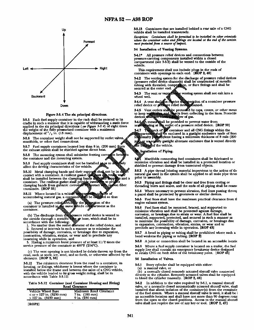
N F P A 52 ~ A98 R O P
Up
Loft , ( / Backward
Forward / > Right
Down
F~,ure S-S.4 The six principal directions.
3-3.5 Each fuel supply container in the rack shall be secured to its cradle in such a manner that it is capable of withstanding a static force applied in the six principal directions ( see Figure 3-3. 4) of eight times tile weight of the fully pressurized container with a maximum displacement of i /~ in. (13 nun).
3-S.6 The container weight shall not be supported by outlet v a l v e s , ~ manifolds, or other fuel connections.
3-3.7 Fuel supply containers located less than 8 in. (200 mm) .~ m the exhaust system shall be shielded against direct h e a t .
3-3.8 The mounting system shall minimize fretting corr~g[!n be in the container and the mounting system.
led t0 affect the driving characteristics of the vehicle.
3-3.10 Metal clamping bands and their su m~knot b ~ i n contact with a container. A resilient gas| ~ p p ~ " | ~s shall be installed between the clamping and a container. The resilient gasket shallpro~ ~.t y clamping bands from galvanic ~ i n fiber containers. [ROP 35]
3-3.11 Where located'in a vehi~ of accumulating natural gas a coW,me .'d so that:
(a) The pressure r e l i e ~ l ~ L ~ c ~ ~ f ~ i o n of the container is installed i ~ same~lh" ~War tment as the container. ~v- V ¢ v
(b) The discharge from ~ s s u r e relief device is vented to the outside through a m e t a l l i c 1 ~ , hose, which shall be in accordance with the f o l l o w i n g : ~
1. No smaller than the outlet dl*,uneter of the relief device, and 2. Secured at intervals in such a manner as to minimize the
possibility of damage, corrosion, or breakage due to expansion, contraction, vibration, strains, or wear and to preclude any loosening while in operation, and
3. Having a minimum burst pressure of at least 11/2 times the service pressure of the container at 400°F (204°C).
(c) The vent opening is not blocked by debris thrown up from the road, sucll as snow, ice, mud, and so forth, or otherwise affected by the elements. [ROP 2, 38]
3-3.12 The minimum clearance from the road to a container, its housing, or fittings, whichever is lowest where the container is installed below the frame and between the axles of a CNG vehicle, with the vehicle loaded to its gross weight rating, shall be in accordance with Table 3-3.12:
Table 3-3.12 Container (and Container Housing and Fitting) Road Clearance
Vehicle Wheel Base Minimum Road Clearance < or ffi 127 in. (3230 mm) 7 im (180 mm) > 127 in. (3230 mm) 9 in. (230 ram)
[ROP2]
3-3.13 Containers that are installed behind a rear axle of a CNG vehicle shah be installed transversely. Except/on: Conta/nsrs s/m//be permitted to be insta/ /a/ in ot/~r o6enta& where Ore contain~ val~e and fiUi~[s are located at the end of the contaiz most p r o ~ . f r o m a sou,u of
34 Installation of Venting Systems.
34.1" All pressure relief devices and connectinn~ between preuure-carrying components installed within a closed compartment (see 3-3.2) shall be vented to the out~ide of the vehicle.
This requirement shall not include plugs in the ends of containers with openings in each end. [ROP 2, 40]
34.2 The venting system for the discharge of pressure relief devices (pressure relief device channels) shall be constructed of metallic tubing with threaded, c o m p r ~ l ~ n , or flare fittings and shall be secured at the outer e n d . ~
34.3 The vent or v e n ~ l ~ ~ venting system shah not exit into a wheel well. ~
34.4 A vent s h a ~ o t ~ t n ' c t ' ~ l p e ~ t i o n of a container pressure relief device or [ ~ e {elief d ~ e l .
34.5 Vent outlets sh] l [~e proteet~ed by caps, covers, or other mean to keep 'u ~ t s from collecting in the line~ Protectiv do 7ces ld ~ ~[ow of ga~
b a l l be provided to prevent water from a t ~ e t of a pressure relief device. [ROP 89]
$ 4 . 7 ~ o f ' l ~ container and all GNG fittings within the arU ~ e ~ enclosed in a gastight enclosure made of lin~,
s ~ylene having a minimum thickness of 8 mils (200 [y gaslight alternate enclosure that is vented directly
[of the vehicle.
tallation of Piping.
$ Manifolds connecting fuel containers shall be fabricated to minimize vibration and shall be installed in a protected location or shielded to prevent damage from unsecured objects.
3-5.2 A pipe threadjoint ing material impervious to the action of th~ natural gas used in the system shall be applied to all male pipe threa prior to assembly.
3-5.3 Piping and fittings shall be clear and free from cutting or threading burrs and scales, and the ends of all piping shall be ream(
3-5.4 Where necessary to prevent abrasion, fuel lines passing throu~ a panel shall be protected by grommets or similar devices.
$-5.5 Fuel lines shall have the maximum practical clearance from tl engine exhaust system.
3-5.6 Fuel lines shall be mounted, braced, and supported to minimize vibration and shall be protected against damage, corrosion, or breakage.due to swain or wear. A fuel line shall be installed, supported, protected, and secured in such a manner as to minimize the possibility of damage, corrosion, or breakage due to expansion, contraction, vibration, strains, or wear and to preclude any loosening while in operation. [ROP 45]
3-5.7 A bend in piping or tubing shall beproh ib i t ed where such a bend weakens the piping or tubing. [ROP 2]
3-5.8 A jo in t or connection shall be located in an accessible locatic
3-5.9 Where a fuel supply container is located on a trailer, the fuel supply line shall contain an emergency breakaway device designed to retain CNG on both sides of the breakaway point. [ROP 45]
$6 Installation of Valves.
3-6.1 Every cylinder shall be equipped with either: (a) a manual valve, or (b) a normally closed remotely actuated shutoff valve connected
directly to the cylinder. Remotely actuated valves shall be equipped to bleed the cylinder manually. [ROP 2, 46]
3-6.2 In addition to the valve required by 3-6.1, a manual shutoff valve, or a normally closed automatically actuated shutoff valve, shall installed that allows isolation of the container(s) from the remalnde of the fuel system. Where a manual shutoff valve is used, it shall be i an accessible location and shall have not more than 90 degrees rotat from the open to the closed positions. Access to the manual shutoff valve shall not require the use of any key or tool. [ROP 2, 47]
341
N F P A 5 2 ~ A 9 8 R O P
Exception: In installations on vehicles not normally operated on public streets, with a single fuel supply cylinder, equipped with an accessible manual cylinder shutoff valve, no additional manual shutoff valve shall be required. [ROP 48]
3-6.2.1 The valve shall be securely m o u n t e d and shie lded or installed in a protected location to min imize damage f rom vibrat ion and u n s e c u r e d objects.
3-6.2.2 The valve shall be m a r k e d with the words "MANUAL SHUTOFF VALVE." Weather- res is tant decals or labels shall have blue or black luminous letters on a white or silver background. [ROP 2]
3-6.3 A valve that automatical ly prevents the flow of gaseous fuel to die engine when die engine is no t runn ing , even if the ignition is switched on, shall be provided in the system. [ROP 21
3-6.4 Where mult iple fuel systems are installed on the vehicle, au tomat ic valves shall be provided, as necessary, to shu t off the fuel no t be ing used.
(b) A label located at the fuel ing connec t ion receptacle shall inc lude the following:
1. Identif ication as a CNC,-fueled vehicle
2. System working pressure
3. Conta iner retest date(s) or expira t ion date.
Exception: I f both labels are located in one of the above areas, the labels s be permitted to be combined into a single label.
5-11.2 Each vehicle shall be identif ied with a weather-resistant, d i amond- shaped label located on an exterior vertical surface or nero vertical surface on the lower r ight rear of the vehicle (e.g., on the t n lid of a vehicle so equipped, bu t no t on the b u m p e r of any vehicle) inboard f rom any o ther markings. Tile label shall be a m i n i m u m of 4~/4 in. (120 mm) long x 3~/4 in. (83 ram) high. Th e mark ing shall consist of a border and the l..e~..~.rs "CNG" [1 in. (25 m m ) m i n i m u m he igh t cen tered in the diam"~"~ ~7.~f. silver or white reflective lumino~
3-6.5* The fuel ing system shall be equ ipped with a backflow check material on a blue b a c k e d . " valve tha t prevents the re turn flow of gas f rom the container(s) to the 3-12 System Testing.~. 5.~{{iii ::'27 "::N_::':.'--:-_...%_::i{~ filling connect ion• The backflow check valve shall be m o u n t e d to withstand die breakaway force specified in 4-11.8. - ...... - 7 . . . . . . . 3-12.1 The co~ ' :"~ig as"'~iembly s ~ i - : ~ - l e a k tested using natural gas
i n s t a l l a t i o n O[ r r e s s u r e t . auges - , , -:-:-:. -:-.'-':::-" • n o n n a m m a m e gas• "%::. ..::i?::"
• • • 3-12 2 Bet 3"~ i~ -~ ..¢.t gye~ :~onnec t ion shall be verified leak free with 3-7 1 A pressure gauge located wldlln a dnve r or passenger • ....:z.:.~:v,..e.:~!:.::: . . . . . . CO . . . . t r ~ o n t ehMl" be~inetMl~.rt in s u c h . . . . . . . t 'ha t n o ~ ¢ ~ q - ~ noncorr0mv~.9.eat~-:~t:~.~'-i.:...~.....l.utlon or a l e a k c t e t e c t o r i n s t rumen t art thr'ot~h~';ile;a~u'~e in £eev~en t o f fa i lu re . . . . . . . . . . o . . . . . . the e .~ )pme i~"~ connec~'~:i~:~:hd pressurized to its service pressure.
o o o " i R ~ g ~ l ",,:.-::..
i ~ ~ i t l i i ~ ~ . . : ~ . ~ e
.-.-:'~i ~::" ':~iil " ~ . . . t ~ c t u r e d before be ing r e tu rned to service, iROP 511
3-8,1 . An au tomat ic pressure reduc ing regulator(s).sb..~":'~!£..:~stM..:!~l 3~.:..[.-"Z5 Where a vehicle is involved in an acc ident or fire causing to reduce die tu f t conta iner pressure to a levet consl...g.tent wt~].:~.t#. "* damage to any par t of die CNG fuel system, die system shall be service ~pressure requi red by die gas-air mixer. ....::::.'-.',~.:-.'::::xx:i:i:~:i:!::" "::i::.:.::!:i~.,....:.:::::.:.:::.~ repaired_ a n d retes ted .(see Section 3-13 ) before bein g r e tu rned to
3-8.2 Means sball be provided to prevent regu.~:or ina~unction}'-:i~j~.~ ~i:" serxqce. to refr igerat ion effects. .::~ii!i'ii:.. '::i-:.:&:, .'-~::, ~."3::" 3-12.6 Where a CNG conta iner is r emoved f rom a vehicle in order t
Regulators t ~ i e : ~ i ~ i . i a o t ~ c e d be installed within a d i f ferent vehicle, it shall be inspected or reteste, 3-8 3 shall be installed SO that -. ." . . . . . . . . . . a ~ . , . , . . . . . . . t . ~ ~ . n - _ "-'~:.-':-:-'~'-.-- " ~i ":r in accordance with the inspect ion or requalif lcation procedures of t]
- - --..::~i:.::.:~:.:'-'~ii.::'.~:':, ":.-:'~..'.:~::.. ,:~;i::" stanctara uncter wmcn tt was or lgmany manutacturect oetore It lS 3-9 Installat ion o f Fuel ing C o n n e c t S ' 2 ""-"~i~! ":-?~i!~i~::::;::!::" reinstalled.
..:~i~i:.-. ..hi.:--... ..-..':: .#::" 3-9.1 A fuelinK connec t ion r e c e ~ ' t a ' N ~ i i ~ i ~ } , l a " : ' S e c t i o n 2-11 shall be installe-d in each v e [ ~ , . : .... "":%i'ii::..- ""-:":':-:""
3-9.2 The fuel ing conne...~i:o'n r ~ t a c l ~ l ~ : : . ~ e m o u n t e d to wi ths tand the breakaw~..~i!'.f.~.r.ce sp@!fied in ~i-t. !:'t". 8. T he receptacle shall be installed in accord~f i~ ! i~ th .t.~'i~ manufa~ ' iurer ' s instructions.
3-9.3 Tbe clearance a r o u n a i i i ~ f u e l i n g connec t ion shall be free of in terference that prevents the :::"::::"'~:....~ion of the fuel ing nozzle• [ ROP 50] .... -::3:" .:+-
-:i::" 3-10 Wiring Installation.
3-10.1 All wiring shall be secured and protected f rom abras ion and corrosion to the same s tandard as die original wiring on the vehicle.
3-10.2 All wiring shall be sized and fuse-protected. [ROP 21
3-11 Labeling.
3-11.1 A vehicle equ ipped with a CNG fuel system shall bear the following durable labels:
(a) A label readily visible and located in the engine c o m p a r t m e n t shall inc lude die following:
1. Identification as a CNC,-fueled vehicle
2. System service pressure
3. Installer 's n a m e or company
4. Conta iner retest date(s) or expira t ion date
5. Total con ta iner water vo lume in gal (L).
3-13 Maintenance and Repair .
3-13.1 Damaged fuel l ines shall be replaced. Fuel lines shall no t be repaired.
3-13.2 All containers , conta iner appur tenances , p ip ing systems, vent ing systems, a n d o ther c o m p o n e n t s shall be ma in t a ined in a safe condition• it shall be verified that the conta iner retest date or expirat ion date is current . [ROP 55]
3-13.3 Pressure relief devices on tile cylinder shall be main ta ined in accordance with CGA S-I.1, Pressure Relief Devices i Part I - - Cylin for Compressed Gases•
3-13.4 Pressure relief devices on all o ther containers shall be ma in t a ined in accordance with the following:
(a) Pressure relief device channe l s or o ther parts tha t could interfere with die func t ion ing of the device shall no t be p lugged by pa in t or accumula t ion of dirt.
(b) Only qualif ied personnel shall be permi t ted to service press relief devices.
(c) Only assemblies or original manufac tu re r ' s parts shall be used in die repair of pressure relief devices unless the in te rchange of parts has been proved by suitable tests.
(d) No pressure relief device tha t has been in service shall be reinstalled on ano the r fuel cylinder. [ROP 58]
3-13.5 The following shall be done du r ing vehicle main tenance :
(a) Close the quar te r tu rn fuel delivery valve neares t tile engine unless eng ine opera t ion is required.
(b) Prohibi t torches, welding, or g r ind ing e q u i p m e n t on or near h igh-pressure fuel lines and containers.
3 4 2
N F P A 5 2 1 A 9 8 R O P
(c) Prevent damage to containers, including actions such as dropping, dragging, or rolling of the container.
(d) Prevent expc.sure of composi te wrapped containers to strong chemicals such as battery acid or metal cleaning solvents.
(e) Store compressed natural gas containers in a manner to avoid damage.
(f) Reinstall containers to their original configuration using approved gaskets, bolts, nuts, washers, etc., per recommendat ions of the container manufacturer .
(g) Prevent hoists or jacks from coming into direct contact with containers.
(h) Prohibit pen;onnel from walking on roof-mounted containers. [ROP 60]
3-14 Discharge o f CNG from Vehicle Containers.
3-14.1 The venting or depressurization of a compresssed natural gas container shall only be per formed by t r a inedpe r sonne l using written procedures. The gas to be removed from the container shall be discharged , nto a closed transfer system or shall be vented by an approved method of atmospheric venting.
3-14.2 Personnel p~rforming container depressurization shall:
(a) Use grounditag to prevent static electrical charge buildup.
4-3.7 Where CNG compression equ ipment is opera ted unat tended, shall be equipped with a high discharge and a low suction pressure automatic shutdown control. Control circuits that shut down shall remain down until manually activated or reset after a safe shutdown performed. [ROP 64]
4-3.8 Engine-driven compressor installations shall conform, where applicable, to NFPA 37, Standard for the Installation and Use of Statio~, Combustion Engines and Gas Turbines.
4-3.9* Compression equ ipmen t shall incorporate a means to minimize liquid carryover to the storage system. [ROP 65]
44 Siting.
44.1 CNG compression, storage, and dispensing shall be located a conducted outdoors or indoors in compliance with this section.
4-4.2 Outdoors . ~iii} .:i:::.:.~::::..
4-4.2.1 CNG storage c o ~ e r s " ~ J ~ a r g e d with CNG not connected f, use shall be located o ~ ! . ! : : . .
4-4.2.2 A facility i~:::~'.[.ch C~.~i:.~ompression, storage, and dispensi~ equ ipment is she[.*~ed":~, an ei~.~.$gr¢: constructed of noncombust i or limited-comb~g.'J.e, materials ~ ; . :~ 'as at least one side predominant ly o p e n " ~ a roof d...~... ~'ned for ventilation and dispers: of escaped:.g.~:~hall be":~'..ma, sidered~to be located outdoors.
44.2.3 .. ~ ~ ~ , and dispensing equ ipment located outdg...~s shall'~::h...e abovegr6"/i'ffd, shall not be beneath electric power
(b) Limit the ra~e of gas release from plastic-lined containers to ling~::~::.where e'~9...osed by their failure, and shall be a min imum of 1 a value not greater than that specified by the container ft ~(:3.(3~.:.'~.}.:..from tfi'~iL~.g..arest important building or line of adjoining manufacturer . .~.p..rgperi~.. t " can b~ii::g~ilt upon or f rom any source of ignition.
(c) Restrain con:ainers dur ing depressurization to prevent .... #!i-:i:~:::!:~i.~.4 Co:~g. .~i~ 'n, storage, and dispensing equ ipment located container movemen:. -i-: o t i~oors shal~:::-.-:~ not less than 10 ft (3.0 m) from the nearest public
. . . . ~i~-:~::-. s.t.~¢ta..~j- s~t~.e~k line and at least 50 ft (15 m) f rom the nearest rail 3-14.3 Direct gas venting shall be done through a vent tune mat Will ":-'!:~:~:~:~::.. ..:::::--":'~::Y.:'.~i-:-,..:¢t . , -:,::::::::...:-~y r ~ mare tracg. divert the gas flow to atmosphere. The vent tube shall have a ~ : : . : . "::i~ii.-i~i~i::. '-:::::: "" tight connect ion to :he container prior to venting and all .::¢:~::::::::i~ili~i!i!~i:: components shall be properly grounded. The vent tube s ~ l be ::~!iii~! constructed of Schedule 80 pipe of at least 2 in. d i a m e t g . ~ 1 3 e ve~{-:': tube shall not be pr 9vided with any feature that would "]im]:~ii~g.::..::#" obstruct gas flow. ..::i::. ":::.:::::::::::
.... ~i'i~~::~ii~::.. '%::i~::.. Chapter 4 CNG Compression, Storage, an.d:ii¢~]s~en~ing S y ~ : ¢ !~:"
4-1" Application. r h i s chapter applies to ~ l a e ' : ~ : ! : : : : ~ s t r ~ . t i o n , installation, and operat ion of eontainer~.~.:~:~essur '~els, co~:~ression equipment , buildings and s t r u c t u r e s , , : ~ c i a t e d : i ~ j ~ n t used for storage and dispensing of CNG..~:"an e r i ' ~ e fuel i"D~i~t and public dispensing operatio.qs. ..::#~i~iii::iii!! ......... ii::!~ii:~-:.:i~:~::::... % -.'J::"
4-2 System Componen t Qua!..i..~tio~:!~ii!~iiiii~stem::~j%nents shall comply with the a p [ ~ r o p r i a t # i l S ~ o n s ~i~.mp. ter 2 and with Sections 4-5 through 4-13..-:::::::::::.A"i! ::~ ":~'."!i!::..:..:. "'~:iiiiiiii~-~ ~ ....
4-3 General. "-":~'::'-~::'~::" ":~:" "-'~!'::" " q : : : : : : : : : : ~
..::-.::-U j . :::~ ,¢ . . - . : . : . : . : . .
4-3.1 Where systems are serv~i....i~)3...agas utility, the utility shall be notified of all CNG installations':":.~e'~:"-". "-:::~ ~:~::." 4-3.2 Equipment related to a c t~press ion , storage, or dispensing installation shall be protected to minimize the possibilities of physical damage and vandalism.
4-3.3* Control devices shall be installed so that internal or external icing or hydrate formation does no t cause vehicle or fueling station malfunction. [ROP 63]
4-3.4 Vehicles shall not be considered a source of ignition with respect to the provisions of this chapter. Exception: Vehicles containing fuel-fired equipment (e.g., recreational vehicles and catering trucks) shall be considered a source of ignition unless this equipment is shut off completely before entering an area in which ignition sources are not permit;ted.
4-3.5 The fueling connect ion shall prevent tlae escape of gas where the connector is not properly engaged or becomes separated. Fueling nozzles shall be listed in accordance with ANSI/AGA NGV1, Standard for Compressed Natural Gas Vehicles (NGV) Refueling Connection Devices.
4-3.6 Compression equ ipment shall be des igned for use with CNG and for the pressures and temperatures to wbich it can be subjected under normal operat ing conditions. It shall have pressure relief devices that limit each stage pressure to the maximum allowable service pressure for the compression cylinder and piping associated with that stage of compression.
'::~i~,.2.5. A clear space of at least 3 ft (1 m) shall be provided for a c t ~O::~!~i~ves and fittings of multiple groups of containers.
4~2.6 Readily ignitable material shall not be permit ted within 10 fl (3.0 m) of any stationary container.
4-4.2.7 The min imum separation between containers and aboveground tanks containing f lammable or combustible liquids sh: be 20 ft (6.1 m).
4-4.2.8 During outdoor fueling operations, t h e p o i n t of transfer (se definition) sha l /be located at least 10 ft (3.0 m) from any important building, mobile home, public sidewalk, highway, street, or road an, at least 3 ft (1 m) from storage containers. Exception: The point of transfer shall be permitted to be located at a less distance from buildings or walls constructed of concrete or masonry materi or other material having afire resistance rating of at least 2 hours, but at least l O f t (3.0 re)from any building openings. [ROP 67]
4-4.3 Indoors.
4-4.3.1 General. Compression, dispensing equipment , and storage containers connected for use shall be permit ted to be located insicle buildings reserved exclusively for these purposes or in rooms within at tached to buildings used for other purposes in accordance with th section.
4-4.3.2 Limits o f Storage in Buildings. Storage shall be limited to n more than 10,000 SCF (283 m s) of natural gas in each building or room. Exception: CNG stored in vehicle-mounted furl supply containers.
4-4.3.3* Deflagration Venting. Deflagration (explosion) venting sh~ be provided in exterior walls or roof only. Vents shaU be permit ted t consist of any one or any combination of the following:
(a) Walls of light material;
(b) Lightly fastened hatch covers;
(c) Lightly fastened, outward opening doors in exterior walls;
(d) Lightly fastened walls or roofs. Where applicable, snow loads shall be considered.
4-4.3.4 Rooms within Buildings. Rooms within or at tached to other buildings shall be constructed of noncombust ib le or limited- combustible materials. Interior walls or partit ions shall be continuous from floor to ceiling, shall be securely anchored, and
343
N F P A 5 2 - - A 9 8 R O P
shall have a fire resistance rat ing of at least 2 hours . At least one wall shall be an exterior wall.
Exception: Window glazing shall be permitted to be plastic. (a) Explosion ven t ing shall be provided in accordance with 4-
4.3.3. (b) Access to the r o o m shall be f rom outside the pr imary
structure.
Exception: I f such access is not possible, access from within the primary structure shall be permitted where such access is made through a barrier space having two. va'p or-sealing,, self-closing doors havin',g the appropriate rating for the locatwn where installed. [ROP 2 ]
4-4.3.5 Indoor locations shall be venti lated utilizing air supply inlets
4-6 I n s t a l l a t i o n o f P r e s s u r e R e f i e f D e v i c e s .
4-6.1 Pressure relief valves shall be so a r r anged tha t they discharge t safe area and. so tha t escaping gas does no t impin, ge u p o n buildings, o ther equ ipmen t , or areas tha t could be occupied by the public. (Se 4.3.10.)
4-6.'/ Pressure relief valves on pressure vessels shall be installed so that any discharge is in a vertical posi t ion and shall be fitted with raincaps. [ROP 2]
4-6.3 An overpressure pro tec t ion device, o ther t h a n a rup ture disc, shall be installed in the fuel ing t ransfer system to p reven t overpressu in die vehicle. The set pressure of the device shall no t exceed 125
and exhaus t outlets a r r anged to provide un i fo rm air m o v e m e n t to the percen t of the service pressure of t he fuel ing nozzle it supplies. ex ten t practical. Inlets shall be uni formly a r r anged on exter ior walls near floor level. Outlets shall be located at the h igh po in t of the room 4-7 Instal lat ion o f P ressu re Regulators . Regulators shall be designe in exterior walls or the roof. installed, or pro tec ted so their..:gperation is no t affected by freezing
. . . . . rain, sleet, snow ice, mud , i ~ . , or debris• This protec t ion shall b (a) Venti lat ion shall be by a con t inuous m e c n a m c a l venti lat ion - e r m i t t e d to be in te- -a l • " ~ ' t h e ~ r u l a t o r fRO P t~l
system or by a mechanica l venti lat ion system activated by a 1" ~ ~ : ~'6~ • t ~J cont inuous ly mon i to r i ng natural gas detect ion system where a gas 4-8 Instal lat ion o f P r ~ t t l g e s . Gauttes shall be installed to • . . . . . .,.::--- ~ concentra taon of no t m o r e than one-fifth of the lower f lammable h n u t indicate comnresslOB :~.t.~char~:it~ressure, s torage nressure, a n d fuel is present . In ei ther case, the system shall shu t down the fuel ing system supply conta iner ~ ! ' p r ~ u r e ~ j ~ . . . . . . ~ " in the event of failure of die venti lat ion system. :~'.:'%~ . . . . . : ~ "
4-9 I n s t a l l a t i o n O f P l ~ , ' ~ g a n d H o s ~ Y (b) * The venti lat ion rate shall be at least 1 f t S / mi n per 12 ft s (1 •":'~-.'~. -:i:.
m S / m i n per 12 m s) of r oom vo lume ,.~:-:.:::: . . . . . "::i~-::- . • 4-9.1 P . ~ # ~ ~ I be run as directly as pracucal with (c) A venti lat ion system for a room within or a t tached to ano the r a d e , q u ~ p r ~ ! o n s " * ~ s i o n ~ , c o n t r a c t l o n , j.arfin~, vibration, m
bui ld ing shall be separa te f r om any venti lat ion system for the o ther s e t ~ : ~ x t e m ~ : ~ l p m g snmt ne e lmer o u n e a or mstaajeo auovegrou hni ldln~ a l ~ ' . ~ . . o e supp~$.tect..anct p ro tec tea against mecnanica i aamage . . . . . . . . ~'" U n d e r " ~ d pipi~':.~"all be bur ied no t less t han 18 in. (460 m m ) 4-4.3.6 Where installed, a gas de tec t ion system shaU be equ ipped to ~.:.,..~.:.][ow ~ l { ' ~ a . c e ~-.'-'~]e g r o u n d unless otherwise pro tec ted f rom sound an alarm a n d visually indicate when a m a x i m u m of one-fifth of ~ " ~ " : : ~ a g e b ; : ' ~ e n " t of the g round . U n d e r g r o u n d a n d abovegroun, the lower f lammable limit is reached. ..::.~ff plating shall ~ i~r"o tec ted f rom corrosion in -compl iance with 4-4.3.7 Reactivation of tile fue l ing system shall be by manua l rest~':~:~{~.~ ~.:X.:ze~..'-- _l~c_~c-es-" T h r e a d e d pipe and fittings shall no t be used a n d shall be conduc t ed by t r a i n e d personnel . .. "~':.~?:.?:$,.:._~'fid~ "'ld. I R O I ' I ~ . . . : ~ . [ ~ll . . . . . . . . . . orris u ~ ~ com ressi s tora ~ " . ~ i : ~ l . 1 Manifolds connec t ing fuel conta iners shall be fabricated to oz--q[..9.o DUilCHn S a n n ro sen tor p on, ~$:-~,a-:..'.-~'.-.-'.~ -~-'..... ..-, . . . . . d i s - e n s i n - shallg~e classified in accordance with Table r .~.~for ~-"" ~ i z e xabration and sha l l 'be Installed m a protec ted locauon or inst~llatioitns of electrical e - u i ~ m e n t . . . . ~ . . ,~-~: s l i | ~ a e d t o p r e v e n t d a m a g e f r o m u n s e c u r e d o b j e c t s .
v -*':" ":~-:'.-':.~ .:.-..-i~:: -~!::" . . . . . . electrical sources of i nif ion o ther th ~ lectri "~2~j~'~'''''':" 4-9 1.9 A pipe t h r e a d j o i n t i n g material impervious to the action o f t • - ~ * . ~ ~ o n , :: ca~ii!:!.-; " . . . . . . . . . . . . . . . . . ~ . . . . . ~ % ":.~::.::, natural t r~ used in file system shall be a n n h e d to all male n ine fl]rez ins ta l lanons as errmttect o ,i-4.o.o, snail n o t oe u. ".:..::..-~. . o - - r r r r p y , , .~,rmr~. " ~ . ,e" n o r to assembly
• . ..:~.~ .:... :.-..-g:,- P • 4.4~.10 Pressure relief dewces on s torage s~C:ms ~ 1 have p r e ~ e . . . . . . . . . . . . . . . . . . . . . rel ief device channe l s Isee 2 5 l¢b~l to con~zd'i~.'.':"~t'-~a, n i ~ a s {~th~'#: ~ . t . ~ a n r e a n e o p ip ing a n n n t o n g s sna~l ne mear a n n tree t rom
. . . . . , , - • , - ,~ _ *~7"~.~v: ' : , .~ .~. ~.. :" cut t ing or d l read ing b u r r s a n d scales, a n d the ends of all p iping shal outooors anct m e n upwaro to a sate a rea to p r e ~ : . ~ . . ~ p m g m l ~ , _ buildings, o ther equ ipmen t , or areas o0...¢~..,.~9 the "l~f,~|c (e . l~ .4. oe reamect.
• R O P ~ ' ~ ' * : ""<:~':-*"" "~" " " " sidewalks). [ 2] ,.-.-::.-"-':'"":::..:'-'!?..~?.-. "~.~).:.~.".-.-......:::'::'~ 4-9.1.4 A b e n d in p~ping or tub ing shall be prohib i ted where such : b e n d weakens die pipe or tub ing 4-4.3.11 Access doors shall have ~ i n g si"~s witi.l dl~-':":~ords .:... . - .~, ;:~ --.'-~ - ~ ; :.'::~ .
"-WARNING--NO S M O K I N G - - ~ ~ ~ I ~ n c h wording 4.9.1.5 A jo in t or connec t ion shall be located in an accessible shall be in plainly legible, bri~..~.~:.{ed | ~ on ~ ; ~ e b a c k g r o u n d with locat ion. letters no t less d]an 1 in ( 7 , , ~ i i ~ T i g l ~ ' ~
• ,i*-" ~i~ %$~.-'~:~.: ,~;:. 4.9.2 Natural gas shall be ven ted only to a sate poin t of discharge, t 4-4.$.12 Indoor Fast Fi~i~uellng,~.~. u t d o o ~ g e , and ven t pipe or stack shall have the open end pro tec ted to prevent C o m p r e s s i o n . Fast f i l ~ g irk dbors is p ~ i t t e d where s torage entraTn/:e o f rain, snow, and solid material . 'Vert ical ven~ pipes a n d a n d compress ion e q u i p m ~ ' ~ f ' 6 c a t e d outdoors complying widt 4. stacks shall have provision for drainatze.
4.9.1, 4-4.2.2, 4-4.2.3, 4 .4 .2 .4 , ' : ~ ~:...5...:..4~4.2.6, and 4-4.2.7. [ROP 69] 4-9.3 The use o l h o s e in an installat ion shall be l imited to the 4-4.3.13 Where a t t ended fast fiff ~ i ~ g is pe r fo rmed indoors: following: [ROP 2]
(a) An emergency manua l shu~ ~ n dewce shall be installed as requi red by 4-11.6. (a) A vehicle fuel ing hose.
(b) A gas detect ion system equ ipped to s o u n d an alarm and visually indicate when a m a x i m u m of one-fifth o f the lower f lammable limit is reached shall be installed.
T h e detector shall shu t down die compressor a n d stop the flow of gas into the s tructure.
46 Installat ion o f Conta iners a n d C o n t a i n e r A p p u r t e n a n c e s (Other than Pressure Rel ief Devices).
4-5.1" Storage conta iners sllall be installed aboveg ruund on stable, noncombus t ib l e founda t ions or in vaults with venti lat ion a n d drainage. Horizontal conta iners shaU have no more t han two points of suppor t longitudinally. Where f looding can occur, each conta iner shall be securely a n c h o r e d to prevent floating. [ROP 2]
4-5.9 Containers shall be protec ted by pa in t ing or o ther equivalent m e a n s where necessary to inhibi t corrosion. Horizontally installed containers shall no t be in direct contact with each other.
Exception: Composite containers shall not be painted without prior permission from the container manufacturer.
4-5.3 Means shall be provided to prevent the flow or accumula t ion of f l ammable or combust ib le liquids u n d e r containers , such as by grading, pads, or diversion curbs. [ROP 21
(b) An inlet connec t ion to compress ion equipment•
(c) A sect ion of metall ic hose no t exceeding 36 in. (910 m m ) in length in a pipel ine to provide flexibility where necessary. Each secti shall be so installed tha t it is p ro tec ted against mechanica l damage a is readily visible for inspect ion. The manufac tu re r ' s identification sh be re ta ined in each section.
4-9.4 At public fuel ing stations, provision shall be provided to recycle gas used for calibration and testing. [ROP73 ]
4-10 Test'rag.
4-10.1 Piping, tub ing a n d hoses, and hose assemblies shall be leak tested after assembly to prove t h e m free f rom leaks at a pressure equ to at least the no rma l service pressure of tha t por t ion of the system.
4-10.2 Pressure relief valves shaU be tested at least every 5 years.
4-11 Installat ion o f Emergency Shutdown Equipment•
4-11.1 A manual ly opera ted conta iner valve shall be provided for ea DOT or TC storage cylinder. Each g roup of ASME storage vessels u F
344
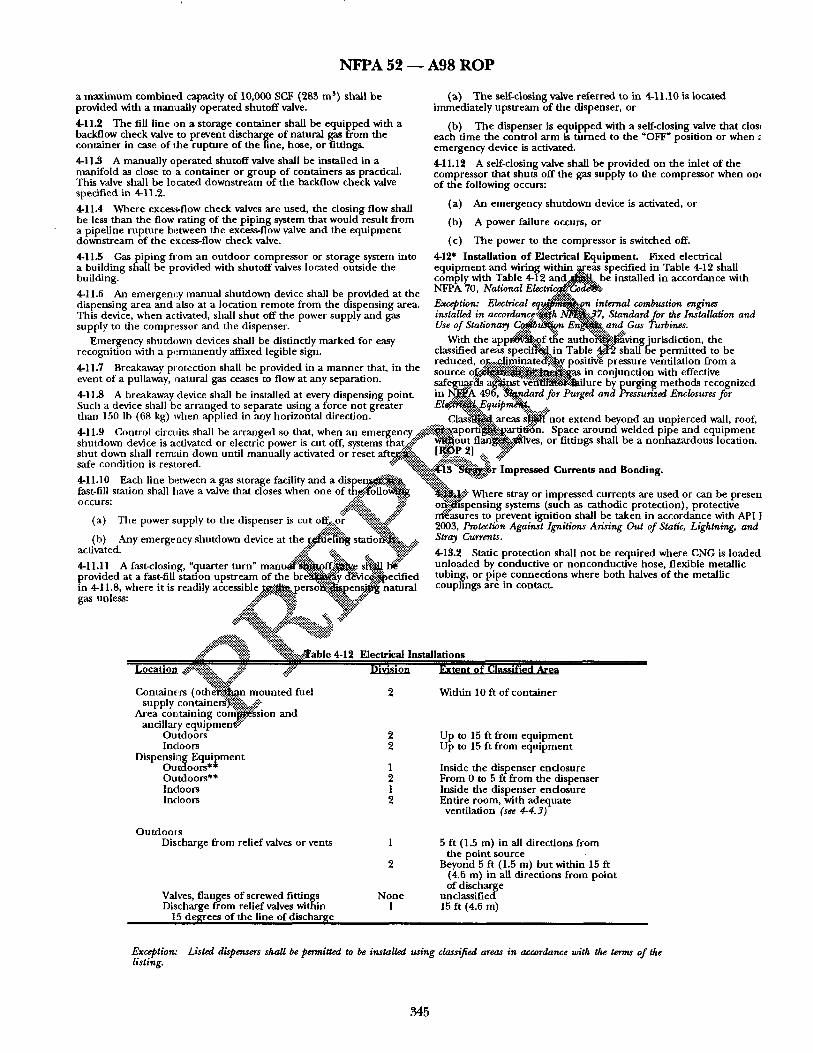
N F P A 52 - - A 9 8 R O P
a m a x i m u m combined capacity of 10,000 SCF (28~ m s) shall be provided with a manua l ly opera ted shu tof f valve.
4-11.2 The fill l ine on a s torage conta iner shall be equ ipped with a backflow check valve to prevent discharge of natural gas f rom the conta iner in case o f the rup tu re of the line, hose, or fittings.
4-11..$ A manua l ly opera ted shutof f valve shall be installed in a mani fo ld as close to a conta iner or g roup of conta iners as practical. This valve shall be located downs t r eam of the backflow check valve specified in 4-11.2.
4-11.4 Where exces:vfiow check valves are used, the d o s i n g flow shall be less t han the flow rat ing of the p ip ing system that would result f rom a pipel ine rup tu re between the excess-flow valve a n d the e q u i p m e n t dd~:nstream of the excess-flow check valve.
(a) The se•cios ing valve re fe r red to in 4-11.10 is located immedia te ly ups t r eam of the dispenser, or
(b) T h e d ispenser is equ ipped with a serf-closing valve tha t dos, each t ime the control a rm is t u r n e d to the "OFF" posi t ion or when emergency device is activated.
4-11.12 A self-closing valve shall be provided on the inlet o f the compressor tha t shuts off the gas supply to the compressor when on, of the following occurs:
(a) An emergency shu tdown device is activated, or
(b) A power failure occurs, or
(c) T h e power to the compressor is switched off.
4-11.5 Gas p ip ing f lora an ou tdoor compressor or s torage system into 4-12" Instal lat ion o f Electrical Equipment• Fixed electrical a bui ld ing shall be provided with shu tof f valves located outside the e q u i p m e n t a n d wiring within .~reas specified in Table 4-12 shall bui lding, comply with Table 4-12 . a n ~ & . b e instal led in accordance with
• . NFPA 70 National Electri ~." 4-11.6 An emergency manua l shu tdown device shall be p rowded at the ' a~. .c~oae~• d i spens ing area a n d also at a location remote f rom the d ispens ing area. Exception: Electrical e q ~ . . ~ o ~ n internal combustion engines This device, when activated shall shu t off the power supply and gas installed in accordanc¢~'~h ~ ' . J . 7, Standard for the Installation and supply to the compr,~ssor, aJad the dispenser . - - Use of Stationary ~..¢.. ''~ "~" ,,: . . . . and Gas r~urbines
• . . . ¢ ~ : : - ' : ~ . . ~:~: . - : f~. . . :~.~" . . . . . Emergency shu tdown dewces shall be disunct ly marked for easy With the a p p ~ ~ l . ~ v i n g j u r , s d i c u o n , the
recogni t ion with a p e r m a n e n d y affixed legible sign. classified areas speciW~, in Table ~.~2 shall be permi t ted to be . . . . . . . . . . . . . . reduced, o~...::~ .170inated:~:;.~y oos i t i~ pressure venti lat ion f rom a ~i i t t~reaxaway nrotec t ion snau De nrovicteo in a m a n n e r that in the . ~:-..:~:.::~..~,-=,~.~ r_--_ . . . . . . . . . • , -- r - . ' source o l ~ : . ~ . ~ . : ~ . . - ~ , ~ a s m c o n j u n c u o n w m emecuve event of a pullaway, Jaaturm gas ceases to now at any separa tmn, s a f e g u ~ l s ~ ~ - ' ~ l f i l u r e by pu rg ing me th o d s recognized 4-11~ A breakaway device shall be installed at every d ispens ing point, in ~:.A 490, ~..#ardfor Purged and Pressurized Enclosures for Such a device shall be a r ranged to separate us ing a force no t greater E l ~ E q u i p n i ~ . . . :+
a . . . . . _ . x ~ : . .6: . : : . .~$.~- than 150 lb 68 k vhen a lied m an hor izontal direction. .- - • ( g) PP Y C l a s g ' d ~ areas s ~ no t ex t end beyond an unp te rced wall, roof, 4-11.9 Control circuits shall be a r ranged so that, when an e m e r g e n c y ~ a , p o r f i ~ i ~ a r ~ . ~ ' n . Space a r o u n d welded pilte an d e q u i p m e n t shu tdown device is activated or electric power is cut off, systems that,:..-.'. ~-+' ~ o u t f l a n ~ + ~ l v e s , or fittangs shall he a n o n h a z a r d o u s locauon. shu t down shall remain down unti l manua l ly activated or reset afteg~..-. [ ~ P 2] ..., .:.:..-'.-'.-':"
• . . ..-.:'~- ~ . Az!~!.:'~.:~ ~'.-~. "~ safe cond iuon ,s restored. - ~ : . . . . . -.~.~:::'¢ . . . . . . . . . . . . . . "~>';~...'..'..'ji~t~ ~ . ~ r ~ m p r e s s e c a ~ u r r e n t s a n d ~ o n n m g .
4-11.10 Each line b~tween a gas storage facility a n d ~ l ~i~ ~'~?:~ ~':'~'~" fast fill s t auon shall have a valve tha t closes when one f - ~ ~..'~,..~!!:- Where stray or impressed currents are used or can be presen
.~'.:-~'-:" or~ib~spensing systems (such as cathodic protect ion) protective :' ..!.-'~ ~:~" n ~ . s u r e s to prevent ignit ion shall be taken in accordance with API 1
a d i s p e ~ ; o f d~..~(.~Gllo~
O C C U R S : ...: ~¢~ ~:':.~i~ ~i: ~ (a) The power supply to the d ispenser is cut off,:..o/" ':'~..~¢..~ (b) Any emergency shu tdown device at the ~ s t a t i ~ . ~ ~. 2sO03tra; Curmnts.Pr°tection Against Ignitions A~ising Out of Static, Lightning, and
activated. "*: " ~ -"-"-'::"~: ~ $" .-.'-'x .~::. ~;.'-~;~-~" 4-13.2 Static protec t ion shall n o t be requi red where CNG is loaded 4-11.11 A fast-closing, "quarter tu rn" m a n u ~ [ ' : ' ~ / ~ : ~ . . e sl=l~. I~" un loaded by conduct ive or nonconduc t ive hose , flexible metall ic provided at a fast-fiU station ups t r eam of the b r ~ c~Mc~i~ecif ied tubing, or pipe connec t ions where bo th halves of the metall ic in 4-11.8, where it is readily accessible ~ $ ~ 2 p e r s o " ~ e n s ~ natural couphngs are in contact. gas unless: .~:"~-".:~ "~*!~.-...£~" x..-'~" "%~ "::,i~..'.~.Y"
-s~,:....y~ . ::-:~::.q:~..:~- . . . . . '~?!'.'x:. ":':.'.'.:-~.~:~:~>"
A:~" .-.'*!, ~]..' .:~::~able 4-12 Electrical Instal lat ions
L o c a t i o n ~ . - . " ~ i ~ ~::: ~'~" Division Extent o f Classified Area • :,~.~! ~.-
Containers ( o t h ~ ~ i ~ m o u n t e d fuel 2 Wid~in 10 ft o f conta iner supply c o n t a i n e ~ ' ) ~
Area cor~taining c o r f i ~ g s i o n and ancillary e q u i p m e n f -~"
Outdoors 2 Up to 15 ft f rom e q u i p m e n t Indoors 2 Up to 15 ft f rom e q u i p m e n t
Dispens ing E q u i p m e n t O u t d o o r s * * 1 Inside the d ispenser enclosure Outdoors** 2 F rom 0 to 5 ft f rom the d ispenser Indoors 1 Inside the d ispenser e n d o s u r e Indoors 2 Entire room, with adequate
venti lat ion (see 4-4.3)
O u t d o o r s Discharge f rom relief valves or vents 1 5 ft (1.5 m) in all directions f rom
the po in t source 2 Beyond 5 ft (1.5 m) bu t within 15 ft
(4.6 m) in all directions f rom po in t of discharge
Valves, f langes o f screwed fittings N o n e unc lass i f i ed Discharge f rom relief valves within 1 15 ft (4.6 m)
15 de~rees o f the line of discharge
Exception: Listed dispensers shall be permitted to be installed using classified areas in accordance with the terms of the listing•
345
N F P A 52 ~ A98 R O P
4-14 Operation.
• 14.1 A cylinder shall not be charged in excess of the design pressure at the normal temperature for that cylinder. DOT, TG, and ANSI/AGA NGV2 cylinders shall be charged in accordance with DOT, TC, and ANSI/AGA NGV2 regulations. DOT, TC, and ANSI/AGA NGV2 cylinders shall not be subjected to pressure in excess of 125 percent of the marked service pressure even if, on cooling, the pressure setdes to the marked service pressure. [ROF 79]
4-14.2 A fuel supply container shall not have a settled pressure above the service pressure that is stamped on the container and displayed on a label near the filling connection, corrected for the ambient temperature at the time of fiUing.
• 14.3 CNG dispensing systems shall be equipped to stop fuel flow automatically when a fuel supply container reaches the temperature- corrected fill pressure (see 4-6.3). Where an overpressure incident that results in operation of the overpressure protection system occurs, the dispenser pressure control system shall be examined and certified by a qualified technician prior to being returned to service.
• 14.4 The transfer of CNG into a fuel supply container shall be performed in accordance with instructions posted at the dispensing station.
• 14.5 Where CNG is being transferred to or from a motor vehicle, the engine shall be turned off.
4-14.6 During the transfer of CNG to or from cargo vehicles, the hand or emergency brake of the vehicle shall be set, and chock blocks shall be used to prevent rolling of the vehicle.
• 14.7 Transfer systems shall be capable of depressurizing to facilita~.~?. "~: disconnection. Bleed connections shall lead to a safe point of ~$..'~ discharge. ~ :
4-14.8 CNG shall not be used to operate any device or eqt - - ~ t h ~ has not been designed or properly modified for CNG servk " ~ . ~ :
• 14.9 Sources of ignition shall not be oermit ted w i t h i r t ~ : 3.~:~], of any filling connection during a transfer operation. ~q"~'~. !
,14.10 A warning sign with the words-"STOP M ~ " ! ! , ~ . ~ SMOKING," "FLAMMABLE GAS" shall be p o s t e . ~ ' / f f l ~ e r and compressor areas. The location of signs s ~ b~.~etert local conditions, but the lettering shall be l ~ : ~ : O . o u ~ o t l ~ and legible from each point of transfer. ~ : ~ : ~ ~: ~.
4-15 Fire Protection. A portable f i r e ~ i s h e ' ~ . g ~ " .z. ing of not less than 20-B:C shall be p r o v i d ~ i . " ~ s p e n s ~
4-16" Maintenance.
• 16.1 Containers and t h ~ : $ ~ . . t e n ~ . ~ p ! < ~ i n g systems, compression equipmenti:,:-~ntrolg'~!:~nd d 6 ~ h a l l be maintained in proper operating c o n ~ . . . . # ; i..-'..-'+! -~"
• 16.2 After the o r i g i n a l " ] ~ . ~ t i o n , vehicle fueling hoses shall be examined visually at such i n ( ~ as are necessary to ensure that they are safe for use. Hose shall be ' ~ ! + $ ' o r leaks per manufacturer 's requirements, but at least annua[|j~..:-:~nd any unsafe leakage shall be reason for rejection. [ROP 2, 8 4 (
4-16.3 While in transit, fueling hose and flexible metal hose on a cargo vehicle to be used in a transfer operation, including their connections, shall be depressurized a n d protected from wear and injury
4-16.4" Pressure relief valves shall be maintained in proper operating condi t ion
4-17 Vehicle Fueling Appliances in Nonresidential Occupancies.
4-17.1 Vehicle fueling appliances (VFAs) shall not exceed a gas flow of 10 SCF/min (0.28 standard cubic meter /min) . VFAs shall be listed.
4-17.2 The installation of VFAs shall be exempt from the requirements of Sections 2-5 through 2-10, 4-2 through 4-4, 4-6, and 4-8 through 4-16.
4-17.3 VFAs shall be permitted to be used to fill stationary containers at vehicle fueling locations. The method of connecting the VFA to such storage shall comply with the provisions of Chapters 2 and 4 and shall be approved. The provisions of 4-17.2 shall apply to the VFA where connected to stationary containers at vehicle fueling locations.
4-17.4 The installation of VFAs shall comply with the requirements of Chapter 5.
Exception No. 1: The requirements of 5-1.1 shall not apply to the installation of VFAs. Exception No. 2: Gas detectors shall be located in accordance with good engineering practice.
• 17.5 VFAs shall not be installed within 10 ft (3.0 m) of any storag Exception: Storage in the vehicle fuel supply container. [ROP 2]
,17.6 Where installed indoors in public assembly and educational occupancies, a VFA shall be located in a portion of the occupancy where NFPA 101®, Life SafeO Code~, or the local building code permits the installation of hazardous equipment. Exception: Where the VFA is located outdoors, the dispensing point may be located indoors without the need for a separate room. [ROP 2, 86]
5-1 Scope.
5-1.1 The exceed 5 S Storage of Exception:
5-1.2
C h a p t e r 5 . . . .~,~ential Fueling Facility
ing facility (RFF) shall not mete r /min) of natural gas.
be stored in the vehicle fuel supply
c ".~, ..ter aplSllg8:'~B:the design, construction installation, on "~5~.?...ma RFF as defined in 5-1.1.
:....Com p o : ~ " Qualificatmns.
~.~ .,.">" . . . ~..~.#Vonents not part of a l~t~d fuehng apphance shal k .~.~"appropriate provisions in Chapter 2. .:.~" ling appliances shall be listed.
shall be exempt from the requirements of Sections 2-5 2-9, 4-2 through 4-4, 4-6, and 4-8 through 4-16.
5-3.1 All equipment related to RFF installation shall be protected t~ minimize the possibility of physical damage and vandalism. This requirement shall be permitted to be met by the use of an enclosure for the compressor package, similar to that of a central air conditior
5-$.2 All equipment related to RFF installation shall be designed fo the pressure, temperature, and service expected.
5-3.3 Vehides shall be considered as unclassified electrically with respect to NFPA 70, National Electrical Code, Article 500.
Exception: Vehicles containing fuel-fired equipment (e.g., recreational vehicles) shall be considered a source of ignition unless this equipment is shut off completely before entering an area in which ignition sources shall be permitted.
5-3A Natural gas shall not be vented to the atmosphere under norr operation.
Exception: Leakage of 1.0 standard in. 3 (1.64 × 10² standard rnm 3; of ga shall be permitted to be released to the atmosphere per fil l ing during disconnection of the fueling hose.
5-3.5 Unless specifically permitted by the installation instructions, multiple VFAs shall not be manifolded together on the discharge sic [ R O P 851
5-3.6 Where more than one VFA are located in a common area, sp between the VFAs shall not be less than 3 ft (1 m) unless permitted I installation instructions. [ROP 85]
5 4 I n s t a l l a t i o n .
5-4.1 G e n e r a l .
5-4.1.1 CNG compression and dispensing shall be located and conducted outdoors wherever practical. However, where not practic (e.g., where inclement weather is common), compression and dispensing shall be permitted to be located indoors.
5-4.1.2 All RFF equipment shall be installed in accordance with file equipment manufacturer's instructions.
5-4.1.3 The RFF shall have a nameplate marked with minimum and maximum gas inlet pressure and flow rate, gas outlet maximum pressure, and electrical requirements. [ROP 88]
346
N F P A 52 - - A 9 8 R O P
5-4.2 Indoor Installations.
5-4.2.1 Where it is necessary to install the compression unit and refueling connections indoors, the compression unit shall be mounted or otherwise located such that the compression ~unit is vented outdoors. [ROP 89] 5-4.2.2 Where the RFF or the vehicle being fueled is located indoors, a gas detector set to operate at one-fifth the lower limit of flammability of natural gas shall be installed in the room. The detector shall be located within 6 in. (150 ram) of the ceiling or the highest point in the room. The detector shall stop the compressor and operate an audible or visual alarm.
5-4.3 Outdoor Installations. The RFF shall be installed on a firm, noncombustible support to prevent undue stress on piping and conduit.
5-12.2 After installation, all hoses shall be examined visually as part this inspection. Hoses that are kinked or worn shall be replaced.
5-12.3 All safety relief valves shall be maintained in proper operatin condition in accordance with the manufacturer's/suppher's recommendation.
Chapter 6 Commercial Marine Vessels and Pleasure Craft
6-1 Scope. This chapter shall apply to all commercial marine vessels and pleasure craft operating on compressed natural gas (CNG), including new and retrofit construction.
6-2 Modifications to NTPA 52, Stamtardfer ~ Natural Gas (CNG) Vdt/mdm~ Fud ~ . 6-2.1 Chaptersl, 2,4, and5 of this standard shall all apply to commercial marine vessels an~pleadure craft operating on
56 Installation of Pressure Relief Valves. Pressure relief valves shall compressed natural gas w i ~ x c e p t i o n of paragraphs 4-14.5, 4- have pressure relief device vents or vent lines to convey escaping gas to 14.6, and 4-14.10. ~ the outdoors and then upwards to a safe area to prevent impinging upon buildings, other equipment, or areas open to the public (e.g., 6-2.2 The following p~V-~U[~ from Chapter 3 of this standard sidewalks). [ROP 21 shall apply to c o ~ m~i~fzvessels and pleasure craft
oporatmg on comj~l~.~s~natuiqtmmS: ~4.1, 3-4.2, 3-4.4, 3-4.5, 3-5.1 54/ Installation of Pressure Gauges. For measurement and test through3-5.8, 3 ~ m ~ r o u ~ h 3 - 6 . 5 ~ , 3-8.1 through ~8.3, 3-9.1, purposes, pressure gauges shall be permitted to be installed but shall 3-9.2, 3-10.1, 3-10.2, ~ . 1 , 3-12.1 t / ~ u g h 3-12.6, and 3-13.1 not be required. _ through 3- 4 ~ . . . ~ h .
5-7 Pressure Regulation. An RFF shall be equipped to stop fuel flow 6.2-~ T ~ ~ | ~ ~ l l P h s shall apply only to commercial automaticallywhenthecontainer(s) reaches the temperature-corrected ~ . ~ e s . ' ~ l e ~ a f t operating on compressed uatural fill pressure.
58 Piping and Hose. 6 . 2 . & 1 ~ a l l a t i o ~ u e l Supply Containers.
gS.1 All piping and hose from the outlet of the compressor shall be n ~ ~0.1.1 "~ ~ s u l ~ y y containers on marine vemels shall be ~ a i t t e d ~t]~Fcated on the weather deck above supplied as part of the RFF. ~ q~.21Lunol f iJ~ and service space or below deck adjacent to 5-8.2 All gas piping to the RFF shall be installed in accordance *tith'~ ~ ~ U'bn and service space, provided all connections to the NFPA 54, National Fud Gas Cod~ ~ ontali~iW re external to or sealed and vented from these spaces.
5-8.3 The use of hose in an installation shall be r e s t r i c t e ~ ~q~ ta ine r s on the weather deck shall beprotected with a following: ~ . / ~ f i g to prevent damage that can occur due to loading~
~l~ading, direct sunlight, and the general use of the vessel. The (a) A fueling hose that shall be limited to a ma~t~gaum l ~ o f ' ousing shall be installed in such a way that contact of the housing
ft (7.6 m) and shall be supported above the floor/~tml~Kd l e v d ~ otherwise protected from mechanical damage ~ abr~ion a n / t ~ g l ~ % 7 v
(b) A maximum of 3 ft (1 m) in length~whL~iW[~gl'~pr~[~nt abrasion damage resulting from vibratiog~4,g~ the l l t i ~o r o u ~ or
both. . ~ ~ 6.2.$.1.2 Each fuel supply container shall be mounted in a 5-8.4 Transfer systems shall be C~l~le of ~l~presst~rizn~rto facilitate location to minimize damage from collision. No part of a disconnection. Bleed c o n n e c t i o ~ g ° q g ~ L ! ~ ~ i n t of container or its appurtenances on the weather deck shall protrude discharge. . ~ - s ~ beyond the sides or top of the vessel at the point where it ,s
s ~ ~ a f t e r amembl ~mU.al to ~ i ~ a x i m u m service
with the container and entrapment of materials that could damage the container or its coating is prevented. The shelter for storing the containers on the weather deck shall be an enclosure constructed of noncombustible or limited-combnstible materials that has at least one side predominantly open , facing outboard, and a roof designed for ventilaXion anddispersal of escaped gas.
58 Testing. All piping ~ l r t u [ after assembly to be proven free of leaks at/~lkessur, mum service pressure of that p o r t i o ~
5-10 Installation of E m e r g e ~ o w n Equipment.
5-10.1 An RFF shall be e q n i p p e ~ i t h emergency manual shutdown of the gas supply and electric powettY. The emergency electrical switch shall be at least 5 ft (1.5 m) from the RFF and in view of the RFF.
5-10.2 Breakaway protection shall be provided in a manner so that, in the event of a pullaway, natural gas ceases to fow.
A breakaway device shall be installed at every dispensing point. Such a device shall be arranged to separate using a force not greater than 150 Ib (68 kg) when applied in any horizontal direction.
5-11 Operation.
5-11.1 An RFF shall be operated in accordance with the manufacturer's instructions.
5-11.2 A fuel supply container shall not be charged,in excess of its maximum allowable service pressure at normal temperature. DOT and TC containers shall be charged in accordance with DOT and TC regulations.
5-114 Where CNG is being transferred to a motor vehicle, the engine shall be stopped.
5-12 Maintenance and Inspection.
5-12.1 All RFF equipment slmll be inspected and maintained in accordance with the manufacturer's instructions.
installed.
6.2.3.1-$ No portion of a fuel supply container or container appurtenances shall protrude beyond the bow or the stem of the vessel. Container valves shall be protected from physical damage using the vessel structure, valve protectors, or a suitable metal shield.
6.2.S.IA Each container rack shall be secured to the vessel frame, either above or below or both, using a method capable of withstanding a static force in the six principal d i reoiom to prevent damage from slippage, loosening, or rotation directiom ( ~ F/gure 3-3.4) of four fim/~ the weight of the fully pressurized container.
6.2.3.12; Each fuel supply container in the rack shall be secured to its cradle in such a manner that it is capable of witimanding a static force applied in the six principal directions (s~ Figuri3-3.4) of four times the weight of the fully pressurized container with a maximum displacement of .5 in. (13 mm).
6.2.3.1.6 The container weight shall not be supported by outlet valves, manifolds, or other fuel connections.
6-2.S.1.7 Fuel supply containers located less than 8 in. (200 mm) from the exhaust system shall be shielded against direct heat.
6-2.S.1~ The mounting system shall minimize fretting corrosion between the container and the mounting system.
6-2.S.1.9 Fuel supply containers shall not be installed so as to adversely affect the balance of the marine vessel.
6-2.S.1.10 Metal clamping bands and their supports shall not be in direct contact with a container. A resilient gasket that does not retain water shall be installed between the clamping bands and their supports and a container.
347
N F P A 5 2 - - A 9 8 R O P
6-2.3.1.11 A container, where located in a below-deck tank room or tank compartment that is capable of accumulating natural gas, shall be installed so that the pressure relief device for the protection of the container is installed in the same space as the container and the discharge from the pressure relief device meets the following requirements:
(a) It is vented to the outside through a metallic tube (vent mast) or hose no smaller than the outlet diameter of the relief device, secured at 12 in. (300 ram) intervals where the tube exceeds 24 in. (610 ram) in length, and has a minimum burst pressure of at least 1.5 times the service pressure of the container at 4 ~ ° F (204°C).
(b) It is located so that the vent opening is not blocked by debris or otherwise affected by the elements.
6-2.3.2 Installation of Pressure Gauges.
6-2.3.2.1 A pressure gauge located within the wheelhouse (bridge) or accommodation or service space shaft be installed in such a manner that no gas flows through the gauge in the event of failure.
6-2.3.2.2 A pressure gauge installed in the engine compartment, fuel container comparmaent, or other gas-dangerous space shall be equipped with a limiting orifice, a shatter-proof dial lens, and a body relief.
6.2.3.3 Labeling. Each marine vessel or pleasure craft shall be identified with weather- resistant, diamond-shaped labels located on an exterior vertical surface or near-vertical surface, at a location, as near to eye level as possible, where the vessel is routinely boarded, both port and starboard. Depending on the size of the vessel, other labels shall be placed at logical locations to alert persons not familiar with the vessel, such as fwe fighters or service personnel, as to the nature of the vessel. The label shall be a minimum of 4 3 /4 in. (120 mm) long by 3 3 / 4 in. (83 mm) high The marking shall consist of a border with the letters CNG,re~c~a minimum o f l in. (25 mm) high, shown in silver or white luminous material on a blue background. . g
6-2.3.4 Operation. A ~
vessel, the engines shaft be turned off. ~ , Exception: It shall be permitted to operate the e n ~ ,h~,~it is ~ces to holdtheve~sel in position while refueling or ~ ~ @ ~ the master, the safety of the vessel is at issue. The permitted to elect to operate generators d~ . ~
6-2.3.4.2 A warning sign ~tl~_ the ~ ~tE~, i n ~ )
~Tv~ss4 stati°ns Smoking," "Flammable Gas shall ns , and compressor areas where it i# ~ -'1 to a dock or anchor buoys. O t h ¢ ~ ~111~ ted with the
location of words "No Smoking," "Flar~ signs shall be determined by 1 .~ . c qn~~ ~ . lettering shall he large enough to be vis~ ~it~th point of transfer.
6,$ Fire Protection for ~r~ '
v e s s 6-3.1 Fire protection for - ~.~d~.be in accordance with NFPA 302, Fire Protection Standard for ,l~'~"re and Commercial Motorcraft, except for the following. 4 F
6-3.1.1" Installation of Powered Ventilation.
6-3.1.1.1 Blower(s) capacity shall be selected in accordance with the blower capacity curve in Fil~re 2-5.2.3 of NFPA $02. More than one blower shall be perrmtted.
6-3.1.1.2 As installed, the blower system(s) shall exhaust air from the boat at a rate in accordance with the system performance curve in Figure 2-5.2.$ of NFPA 302 when the engine is not operating and the blower is operating at the electrical system's nominal voltage.
6-3.1.1.3 Blowers shall be mounted above the normal level of accumulated bilge water. Exception: Submersible blower motors.
6-3.1.1.4 Blowers shall be installed with ducts having intake openings that are:
(a) Permanendy secured;
(b) Located in the upper one-third of the compartment;
(c) Located above the normal level of accumulated bilge water;, and
(d) Located as near below the engine(s) that they serve as practicable.
6-3.1.1.5 Electrical wiring shall be installed in accordance with Chapter 7 or Chapter 8 of NFPA 302.
6-3.1.1.6 Each boat that requires a powered ventilation system shall display a warning label that provides the information that follows, located in plain view of the operator, and located as close as practicable to each ignition switch (including auxiliary equipment) .
The powered ventilation label shall read as follows: WARNING
Gas Can Explode
1. Check Engine Comparm~ent for Gasoline, Gas, or Vapors 2. Operate Blower for 4 ~ t e s
(a) Be gaslight to
l ~ a ~ m i n from vibration, shock, (c) Be supportec imizefi~1ure
(d) s into nonmetallic exhaust system
~ ( e ) ~ e no d r a y a g e from other devices into the exhaust. :. ~ t i T - ~ n e - ~ n g water or exhaust-cooling water.
NFP i ~ a l l have precedence over the requirements of L ~ N O ~ I ~ 5 0 as .[~y relate to the use of compressed natural gas.
I ~a~°tecti°n f°r Marinas and B°atyards"
~i e protection for marinas and boatyards shall be in ce with NFPA 303, Fire Protection Standard for Ma~inus and
except for the following.
6-4.1.1" Storage and Handfing of Fuels.
6-4.1.1.1 The fuefing station shaft be located to minimize the exposure of all other plant facilities. All fueling stations shall be accessible by boat without entering or passing through the main berthing area. Exception: Where inside fueling stations are made nscessae~ by prevailing sea conditions (wake, surge, tide, etc.), such stations shall be located near an exit by water flom the berthing area or at some other location from which, in case of fire aboard a boat alongside, the stricken craft can be quickly removed without endangering other boats nearby.
6-4.1.1.2 All boat fueling operations shall be carefully accomplished in accordance with NFPA 302, Fire Protection Standard for Pleasure and Commercial Motor Craft, and this standard, at the fueling station or other specifically designated remote location.
6-4.1.1.$ No tank barge or other fuel supply boat shall be permitted within the ber thing area. Outside berths and connections shall be provided for the use of tank barges or fuel supply boats.
6-4.1.1.4 Fuel storage tanks shall be installed in accordance with NFPA 30A, Automotive and Marine Service Station Code, and this standard.
6-4.1.1.5 Fuel storage tanks shall be securely anchored where they are located subject to flooding or tidal conditions, and the applicable precautions outlined in Chapter 2 of NFPA 30A, Automotive and Marine Service Station Code, shall be observed.
6-4.1.1.6 Fuel storage stanks and pumps, other than those integral to approved dispensing units supplying gasoline, Class I, or Class II flammable liquids at marine service stations, shall be located only on shore, or with the express permission of the authority having jurisdiction, on a pier o f solid-fill type. Approved dispensing units with or without in tegra lpumps shall be permitted to be located on shore, on piers of solid-fill type, on open piers, wharves, or floating piers.
6-4.1.1.7 Tanks and pumps supplying diesel Class III flammable liquids at marine service stations shall be permitted to be located on shore, on piers of solid-fill type, or on open piers, wharves, or floating piers. Class III flammable liquid tanks that are located elsewhere than on shore or on piers of the solid-fift type shall be
348
N F P A 52 - - A98 R O P
limited to 550 gal (2.08 m s) aggregate capacity. Pumps not a part of the dispensing uni t shall be located adjacent to the tanks.
6-4.1.1.8 Fuel pipelines shall be installed in accordance with the provisions of NFPA 30A, Automotiv# and Mari~ S~a, ic, Station
64.1.1.9 Dispensing units for transferring fuels f rom storage tanks shall be in accordance with the provisions of NFPA 50A, Automo#i~ and Marine ~ Sta6on Code, and this standard. Gasoline
. ~ An engine or engines on the weather deck shall be mounted in a location that shall ensure minimum damage from collision. No par t of an engine or Its appurtenances shall protrude beyond the sides or top of the vessel at the point where i t is installed.
g6JS.6 No portion of an engine on the weather deck shall protrude beyond the bow or stern of the vessel.
delivery nozzles shall be equipped with a self-closing control valve 66-6.6 Natural Gas Moni tor in l that will shut of f the flow of fuel when the operator's hand is . --~s. removed from the nozzle. The use of any device to override this 6-6.6.1 Engine Rooms. safety feature is prohibited. The nozzle shall be inspected daily for 6-6.6.1.1 Engine rooms shall have at least two natural gas detectors proper operation. Any nozzle that shows evidence of possible placed near the ceilin~ at the fore and aft locatiom malfunctio* n or leaking shall be removed from service. The use of ~ . . ° . . - - -" any automatic nozzle with a latch-open device is vroblbited for the 6-6.6.1.2 Momtormg stations shall be located m the engine room, delivery of wasoline. In the construction of the ~ e l hose assemblv, in the wheelhouse (bridge), and in an accommodation or service provision si~all be made so the fuel delivery nozzle is properly " space, such as a galley, where crew members are likely to bonded to the shore electric grounding facilities as reqmred in congregate. Section 3-6 of this standard. 6-6.6.1.5 When no gas ~ e c t e ' ~ the monitoring s~tions shall 6-4.1.1.10 Gasoline and other flammable liquids stored in drums show a green light. or cans shall be kept separate from other plant facilities, and stored 6-6.6 IA At one- ten t l i f f the'lliKer flammable level (LFL~ of the and dispensed in accordance with applicable requirements of con~nt ra f ion ,~,,~gr ~ ' ~ B ~ t l ~ t ; ~ n activate stmub~""ousl~ with NFPA 30A, Automotive and Marine S~v/ce Star/oft Code. a flashing y e l l o ~ a c ~ " m p ~ n i ' ~ klaxon'a't eac'~l~or~iltoring 6-4.1.1.11 Hand carriage of gasoline within the plant area shall be station. ~ ~ , restricted to containers designed for. carrying and storage of such 6-6.6.1J; ~ l m a s a ~ g J ~ R r i n g systemte Cdetects a concentrauon" that fuel. Open buckets, cans, or glass jars shall no t be used. is o n ~ g ~ e d light accommnied by a siren 66 - " -is n " s h a l l ~ c a t e ~ a c h " ~ m ~ I ~ n g K a t i o ~ When the ne--flfth LFLis
.uel tJ pe stag. ~ - s y s ~ n - - ~ i ~ an emergency fuel shutoff 66.1" CNG dispensing shall be in accordance with NFPA 30A, sh~l ~ t i v a t e d ~ m e o u s l y , which will terminate the flow of iutamo6w and Marine ~ Station Code, except for the following. ~ to ~ e r ~ .
6-5.1.1 The design, fabrication, assembly, test, and inspection of ~ J ~ . l . 6 ~ override switch shall be mounted in the engine the plping system shall be in accordance with NFPA 30, F/ammaMe ~ r o a n so that~LVcrew can turn off the alarm and restore fuel to the and C.ombust/b/e L/fu/ds Code, Chapter 3, and this standard. ~ . ~ m ~ _ . ~ ~ L ~ e v e n t of a false ~ a r m or o ther contingency.
66 Engine Rooms or Engine Compartments. . , ~ e ~ "~[~-6.6.1"~qWqhen the compre~eed natural gas fuel supply is shut ~ due toloss of env fllation or detection of gas, the master shall
" . I Location of Fuel Lines in Engine Rooms and . E a g l e . ~ ~ @ t h a t ~ e cumpres~_ed, natural gas fuel supply is not used until Compartments. All fuel lines shall be mounted near t h ~ [ ~ a g ~ t h ] ~ a k or oth re catise of the shutdown is f o u n d and corrected. order to provide the shortest route for leaking gas to f l /~ t ' 8 ~ e ~V exterior. " ~ 6-6.6.2 Engine Compartments. Engine compartments shall be
_ equipped with natural gas detection and shutoff system as required 66.2 Fuel Line Pressure. The pressure in the~ " ~ for engine rooms, except that a monitoring station shall be placed through the engine room or engine c o m p a r t ~ . . c ~ only at the wheelhouse (bridge). If the vessel is large enough, the pressure required to operate the e n g a n e ~ ' ~ however, and the alarm cannot be heard if no one is manning the
wheelhouse (bridge), then the equipment shall also be placed in accommodation or service space.
~ n ~ passing shoot
. . $ Pressure Regulators. All pressugMmgtalat ~ e p t ~ e mounted on the engine(s), shaN b e ~ t or compa nent. L 664 Ventilatlou " . 4 . 1 Engine rooms or c ~ a e n ] ~ l Ix /~ovided with positive pressure and ~ v e n ] ~ i o n . ~ [ ~ .- pressure ventilation shall p r o v i ~ m ~ h of 30 ~ f n ~etric exchanges per hour. ~" ~ h ~ q
" . 4 . 2 The ventilation s y s ~ l be capable of handling a combustible mixture, if n e ~ ventilation fans shall take air from the weather deck and d i ~ e it back to the weather deck through ducts that shall h a ~ a maximum separation from the fans. Multiple discharge ducts shall be used if practical to enhance
. . 7 PLre Equipment and Systems.
. . 7 . 1 Compressed natural gas--powered marine vessels of all sizes shall carry fire equipment and systems that are required by the U.S. Coast Guard.
ventilation.
. . 4 . 5 If engine combustion air is taken from the engine room or engine compartment, the 30 air exchanges per hour shall be in excess of the maximum air volume per hour required by the engines.
. . 5 Engines.
6-6.5.1 Since compressed natural gas engines have a natural gas atmosphere in the crankcase, they shall be provided with blowout plugs to relieve pressure in the event of a c/ankcase explosion. Blowout plugs shall be located so as to limit risk to the crew.
, . 5 . 2 Engines shall be permitted to be located on the weather deck.
, . 5 . 3 Engines loc~-tted on the weather deck shall be protected with a housing to prevent damage that can occur due to loading, unloading, or the general use of the vessel.
, . 5 . 4 A shelter for an engine installed on the weather deck shall be an enclosure constructed of noncombustible or limited- combustible materials that has at least one side predominantly open, facing outboard, and a roof designed for dispersal of escaped gas.
. . 7 . 2 In addition, engine rooms and engine comparUnents shall have a 150°F (66°C) thermal switch that sh/ql a e r a t e fire-fighting equipment. When the thermal switch is activated, a flashing red light and an audible alarm shall activate in the engine room wheelhouse (bridge) and other accommodation space or service space where crew are likely to congregate, such as-a galley, signaling the possible presence of a fire.
, . 7 . 5 There shall be a one-minute time delay, after which the engine room or compartment shall be flooded with CO~ for two minutes. Simultaneously, the ventilation fans shall be cut off for two minutes and then reactivated. Sufficient COp shall be provided for two cycles.
. . 7 . 4 A manual override switch shall be provided in t hceng ine room or near the engine compartment to allow termination of the response in the event of false alarm or other contingency.
6-6.7.5 Controls shall be provided to allow manual activation of the COp system without a delay.
6-7 Tank Rooms or Compartments.
6-7.1 Tank rooms and tank compartments shall be airtight as well as watertight with appropriate fittings used to seal penetrations through the bulkheads for wire or pipes passing through the tank rooms.
6-7.2 The tank rooms shall be provided with positive pressure and passive ventilation.
6-7.5 Ventilation of the tank rooms (compartments) shall be provided at thirty exchanges per hour mimmum.
349
N F P A 52 ~ A 9 8 R O P
6-7.4 Air shall be taken f rom the weather deck a n d discharged back to the weather deck t h r o u g h ducts that have a m a x i m u m separa t ion f rom the fans.
6-7.5 The fans shall be capable of h a n d l i n g a combust ib le mixture , if necessary.
6-7.6 Multiple discharge ducts shall be used if practical to e n h a n c e ventilation.
6-7.7 Natural Gas Monitor ing.
6-7.7.1 Tank rooms or compar tmen t s shall have at least two natura l gas sensors placed a t or nea r the ceiling at fore a n d aft locations.
6-7.7.2 W h e n no gas is detected, the mon i t o r i ng stations shall show a g reen light.
6-7.7.3 Two levels of a larm shall be used for s ignal ing the need for
6-7.11 Light ing .
6-7.11.1 Tank rooms shall have at least two explos ion-proof l ighting fixtures.
6-7.11.2 Switches a n d overcurrent protective devices for l ighting in the tank room(s) shall be in a gas-safe space.
6 8 V e n t Mas t s .
68.1 All crankcases on natura l ga s -powered eng ines shall be ven ted to a ven t mast. Vessels having more t h a n one engine shall be pe rmi t t ed to utilize a manifold.
68.2 Relief valves or c o m m o n vent headers f rom relief valves shall d ischarge to a ven t mast.
6-8.3 Vent masts shall m e e t the following requ i rements :
intervention. (a) Discharge vertically ~ d 6-7.7.4 An a la rm shall activate when one- ten th o f the lower ~$¢ ~.t..~,. explosion l imit (LFL) is de tec ted by a moni tor . A f lashing yellow . (b) Have a rain cap ~ e r rdeans of prevent ing file en t rance li h t a n d a klaxon . . . . . shall be activated in the engine r o o m a n d in the o t ra in or snow ~g#: "~:~ . . ~ e e l h o u s e (bridge) as well as In all a ccommoda t i on or service . . . . . . . . ."~,~ , :~,'_'a . . . . . . . . . . . . . . . . ' . (c) ~ x t e n a t o a ~ e a ~ ' ~ n e l ~.-'.~. l O t t ( 3 m ) a n o v e m e n l nest space (such as a galley) where crew are likely to congregate . . . . . 7~.-.x.>. " *:.,. ~ ! ~ .. g . . . . . . , . • working level on....tg~..vesso'l. ":$~::.<..:.....::::- Simultaneously, power ventalation shah activate, u n vessels wlttl a ~..::,.~X.~i~. x:..-.:.:.:!!%.:.~::, tank compar tmen t , a f lashing yellow light a n d an audible signal 6-8.4 Relief valve vet~!~.as..ts and e ~ n e ventilation vent masts shall shall activate in tile whee lhouse (bridge). If the vessel is large no t be con~,y:ff~..gd, bu t ~ 1 be per]hilled to te rmina te at the same e n o u g h that the a larm canno t be hea rd if no one is m a n n i n g the locat ion . . : ~ i ~ ~
. . . . . .,"-:~" '::'~:~ "''~':~:+.-'.~-'~:~-'.~::~.%'~5:~::-. whee~l~ouse (bridge), a s econd warn ing stataon shall activate in an .:~: :~.:::. ......... :."-'.:-'.'.-'.:x~:- a c c o m m o d a t i o n or service space where crew are likely to 6-9 . . :~ luge $~...e.ms. congregate. 6-~'-':.'i~.~.h delu~1~. t . .~m that protects more than one area shall 6-7.7.5 At one-fifth of LFL, a second a larm shall activate utilizing a have a t ' : : ~ one]s"?.'..~:bn valve at each b ranch connec t ion and at f lashin~ red licht a n d a siren. These m o n i t o r i n g stat ions shall be ...:.::~.'..~..~t o n e ] ~ . t i o n ~i:lve downs t r eam f rom each b ranch connec t ion p l aced~n the s%me locat ions as the mon i to r ing s tat ions for the one- .~::"'~ f~ .~o la t e d ~ ¢ t ~ l sections.
tetdo~nLFcL fue~s~nudo~tonalevfiftlwi~llLffteLinWarantm~2saCdnVatedalgas fro~::.:.::~...:..i~ii~....,..~.,.x~~edloCrOte~c~Oonnt~c~on/~lomta~ deloUmg%System to the
tile tank r o o m or compar tmen t , venti lat ion shall te rminate , CQ:~:::: .... ' : ~ . ~ o m n ~ n t shall f lood the tank room, and a water de luge system shall h.~:,:"':"-'?~-T-9.':~: "-'~.'-'~.~ . . . . . . . . . . a r t i ~ t v d ::~:" v~" "~...-:~:Each pipe, f i t t ini , and vmve tor m e aemRe system snai~ De . . . . . . . . . ~{ii .... ~#": ~ ' ~ o f fire'-resistant a~ad corrosion-resistant materials such as 6-7.7.6 A tank c o m p a r t m e n t shall no t be permi t ted t o ~ . - " ~ L ..#:: g ~ n i z e d steel or galvanized i ron pipe. de luge system if a vessel is too small to a c c o m m o d a t e . t h e "%"~!ii:.-:.::~Y" e a u i n m e n t The : u d ~ e n t will be made b" the a m ~ ' ~ h a ~ : ' : 6-9.4 Each deluge system shall have a m e a n s of dra inage in order ju r i sd ic t ion A.'- . . . . . ":-' "%'$:...~...-.~:. to prevent corrosion of the system a n d freezing of the accumula ted
• ::5::'::" ~::. ":~'~'.;~" water in subfreezing tempera tures . 6-7.7.7 When the compressed natural gas fi~.'.~.ppl~shu~.:.d.ow~;:::: - . . . . . . ~ . . . . . . . . . due to loss o f venti lat ion or de tec t ion of , ~ ~ ~ t a a l f i ~ i - : • " t~u.b Each ae luge system snail nave a a i r t s t ra iner m a t is iocatect at
~' ' ~: ~'--" ~ *~:::" tile delu e system mani fo ld or u m ensure tha t tile compressed natural gas fq~l s u ~ : : . u o t use~ii~ntil g P P" the leak or o ther cause of the s h u t d ~ n d ~ ' ~ . ~ . ~ $ : . ~ d . 6-9.6 Water to the de luge system shall be suppl ied by a p u m p that 6-7.8 Tank rooms and c o m p a r t l n g ~ shal[l~ave m ~ r a l n s is only for the use of the system. that remove the water p r o d u c e d ~;."~,~del~::$...~.t~f~. "::'Y" ~ . . . .
"::: -..:.-jL.:.~..::.....:~..~:~i~:Z.:::..:-i?. " ~-lU A l a r m ~ y s t e m s . 6-7 9 A labeled override swi~:k~.~all:~{.'~lab~.-".~!-"a readily . . . . . . . . . . . . . . . .
• . . . . . ~ : . : . . ' ~ ] : ~ - - ' - r . . ~ : i ~ : ~ . " . U - I U . I l n e gas ctetecuon a larm systems s n a l i n a v e a m ean s oi accessible lOcation to turn...otr'tr~:.":..~n~ r ~ : o r . c o m p a r u n e n t ; n ~ l ; P ~ f ; n e urh;eh nmt,,r~l t r ~ ¢ ¢~nSO r h~¢ hoen act;,~*~d warning system in file e v # of a ~ a l a r i ~ l e r cont ingency . . . . . . . ~ . . . . . . . . . . . . . . ~ . . . . . . . . . . . . . . a n d to shu t down the ~ n d d # g e syste~:" 6-10.2 The fire a larm systems shall have a m e a n s of indicat ing
• -v "~i~::. ::';~$ "~:" which thermal switch has been activated. 6-7.10 Fire-Fighting E q u l p ~ . . . . 6-10.3 Ead~ audible alarm shall be a r ranged so tha t is can be 6-7.10.1 Tank rooms. ,and c o m ~ : . ~ n t { , shall have .a 150°F. (66°C) t u rned off after sounding . For a remote gr, pup alarm, this me rma i SWltCn m a t Will acuvate a ~ u c n r e - n g n u n g equipment , a r r a n g e m e n t shall no t in te r rup t the alarm s actuat ion by o ther
6-7.10.2 W h e n the switch is ac t i~ ted , a red f lashing light and an faults. audible a larm shall activate on a fire a larm panel in the 6-10.4 Each visual a la rm shall be one that can be tu rned off only wbeelhouse (bridge) a n d in an accommoda t i on or service space (such as a galley) where crew are likely to congregate .
6-7.10.3 Since the tank rooms or compa r t men t s are u n m a n n e d spaces, a larms shall no t be requ i red in those spaces.
6-7.10,4 Ventilat ion in file tank rooms or compa r t men t s shall be t e rmina ted s imul taneous ly with the activation of the fire alarm. One minu te after tile fire a larm is activated, the tank room or c o m p a r t m e n t shall be f looded with CO v and a de luge system shall activate to keep the compressed natural gas cylinders cool a n d to assist in t e rmina t ing fire.
6-7.103 The tank room or compatvanent sball be provided with a readily accessible override switch ti~at will allow the crew to te rminate the fire-fighting system in the event of a false alarm or o ther cont ingency.
6-7.10.6 A deluge system shall be permi t ted to be omi t ted f rom tank compar tmen t s on vessels flint are too small to a c c o m m o d a t e them. This de te rmina t ion shall be m a d e by the author i ty having ju r i sd ic t ion .
after the fault tha t ac tua ted it is corrected.
6-10.5 Each vessel shall have m e a n s for test ing each alarm.
6-10.6 Gas-safe spaces ad jacen t to gas dange rous spaces, such as engine rooms and tank compar tmen t s , shall have positive pressure venti lat ion systems capable of 30 exchanges an hour . Their venti lat ion shall activate whenever an a larm is activated°
6-11 S a f e t y E q u i p m e n t .
6-11.1 Marine vessels with tank rooms a n d engine rooms shall have:
(a) Th ree self-contained, p ressure -demand- type , a ir-breathing appara tus approved by the Mining Enfo rcemen t and Safety Adminis t ra t ion (MESA) or the National Insti tute for Occupat ional Safety a n d Heal th (NIOSH), each having at least a 30 -minu te capacity
(b) Three spare bottles o f air for tile self-contained air b rea th ing apparatus, each having at least a 30-minute capacity
(c) Three exp los ionp roo f flashlights
350
N F P A 5 2 - - A 9 8 R O P
(d) Three helmets that mee t the safety requirements for industrial head protect ion, ANSI Z-89.1, Personnel Protection - - Protective Headgear for Industrial Workers i Requirements, 1986
(e) Three sets of goggles that meet the specification ANSI Z- 87.1. Practice for Occupational and Educational Eye and Face Protection, 1989
(f) An air compressor to recharge the bottles for the air- breathing apparatu
(g) Portable hand-held natural gas detectors which shall be provided to aid in evaluating alarms and for making a survey of the vessel. These instruments shall allow locating specific leaks at very low levels of detect ion and shall be carried by personnel working in a compar tment corttaining gas storage or transmission equipment . A vessel with a tank room shall have at least two of these sensors.
6-11.2 Vessels having engine rooms and tank rooms shall have a portable analyzer tttat measures oxygen levels in an inert a tmosphere .
6-11.3 Before allowing anyone to enter a space that has had a gas leak that has been repaired, the master shall ensure that the space has an oxygen concentrat ion of at least 19.5 percent oxygen by volume and is free of natural gas.
6-11.4 The master :;hall ensure that the compressed air b rea th ing - equ ipment is inspected at least once a month by licensed officer and that the date of inspection and condit ion of the equipment is placed in die vessel "s ]log.
ANSI Z 89.1, Personnel Protection i Protective Headgear for Industrial Workers - - Requirements, 1986
ANSI Z 87.1, Practice for Occupational and Educational Eye and Face Protection, 1989.
7-1.2.3 API Publication. American Petroleum Institute, 2101 L Stre, NW, Washington, DC 20037.
API RP 2003, Protection Against Ignitions Arising Out of Static. Lightnin~ and Stray Currents, 1991.
7-1.2.4 ASHRAE Publication. American Society of Heating, Refrigerating and Air-Conditioning Engineers, Inc., 1791 Tullie Circ NE, Atlanta, GA 30329-2305.
ASHRAE Handbook Fundamentals, 1993.
7-1.2.5 ASME Publications. American Society of Mechanical Engineers, 345 East 47th Stre...~....,.:....New York, NY 10017.
ANSI/ASME B31.3, C h ~ c ~ : f i ~ n t and Petroleum Refinery Piping, 1993. ,::.:.:~i~!iiii::::i::~::.
ASME Boiler and P..~ur~:i!~...l Code, Section VIII, 1992. : .% "~-::.% x.-'.:'.~::::'.:..
7-1.2.6 ASTM P u . ~ a t i ' ~ . @ ~ a ~ i : S o c i e t y for Testing and Materials, 1916 ~i~ii~.treet, Philad:~!~ia, PA 19103.
ASTM A47, Standa~ii~pecificati~'::"for Verritic Malleable Iron Casting., 1990. ..::ii::::?:?:?:i::::ii::::iiiiiiiiiiiiiiii:i:::::..::::.:.:.£1~'ii:-::.::..
AST...~i::"A'~;i":'~:'~:~:~'~.!::~fication for Ferritic Ductile Iron Pressure- Reta.i~"..ng Casti'~{.for Use at Elevated Temperatures, 1988.
- : ~ : . A 5 3 6 , ~ d a . ~ Specification for Ductile Iron Castings, 1984. 6-12 Safety Trainir~g. ASTI~-~'~:36, S t a ~ r d Test Method for Behavior of Materials in a 6-12 1 A written saiety guide for the vessel and for the safety ......... i i ~ i c - l T u ~ i i ~ . - - - ~ - , '7~0 n . . . . . . . ." . ..::!:::-::'::-:Y..~.~ ~* x v~.::~Ht~..o~ ut / J uegrees t~, lUSt. e q m p m e n t and pro cedures shall be provided. The manual sball ..::~i:: . . . . . ::~;;::i ".)~i~!i!:::-~:::!i::" . outline all safety sy~;tems and equipment and their operation. .~ii~:, i!~ScM 3.8Oii!~ndard Practice for Use of the Internatwnal System of V
6-12.2 Crews shall be trained to operate file compressed natural ":'~i::""~!!~::,..;~f~.i~!!!: "::" gas powered vessel ~nd to perform repairs . . . . . . . i:i ...... "%iii--"::i~-1.2.7":':~. Publication. Compressed Gas Association, Inc. 1725
. . . . -i;i::::::::iiiiiii? " - ~ e r s o n Davis Highway Suite 1004 Arlington VA 22202-4102. 6-12.3 Training drills shall be conducted monthly. .::i-: :::::: -:::::::-::.9 ' ' ' ..::-i::iiiiik. .?:?:::i . . . . i ~ A S-I.1, Pressure Relief Denice Standards - - Part I - - Cylind~s J,
-:;i:::"::i:'::iiii.:i . . . . . . . :~!i . . . . Cdgehpressed Gases, 1994.
"::'::':::':~i?:-.:::":~" :::::" 7-1.2.8 CSA Publication. Canadian Standards Association, 55 Chapter 7 Referenced Publica~i!!!i!~i::" , .........
7-1 The following documents or portions the~.~of at:.e, refer.ence~ii~iii~ i::" within tiffs s tandard as mandatory requi rem~i~. .~ , d ~ t J . b~i::ii~::, .:-i -?:" considered part of die requirements of this ~ t a / ~ / ~ : - e d f . ~ . ~ . n indicated for each ~'eferenced mandator.]/.::~.9.cume"@i~:..the cu..#~'nt edition as of the date of the NFPA iss#~d:~::::~ this s '~ .ar~! : :"Some of these mandatory documents might...a.#'o be ~ e r e n c e d " ~ i ~ i s standard for specific informational p u r p o ~ i ~ d , d).~g.9..re,~...ro~]so listed in Appendix B. ~:~ ":~iiii~<-":"~:.:~::::'#:""~<:~:~!~!iiiii~ •
7-1.1 NFPA Publications" , ~ Fi"~!~.$~tec.;';:~:"'Association, 1 Batterymarch Park, P.O. ~ x 9101%~uincy:;::!~02269-9101.
NFPA 30A, Autorno~i~..M#'~e'""" - - ~ Servic@~:"ation Code, 1996 edit ion. "::::::::-':- :-':::~ "~::..-:'~:':-.
NFPA 37, Standard for the ? ~ l a t i o n and Use of Stationary Combustion Engines and Gas T~rbines, 1 9 9 4 " : ~ .
NFPA 54, National Fuel Gas ~ " 1 9 9 2 edition.
NFPA 70, Natior, al Electrical Code, 1996 edition.
NFPA 101, Life 5'ado 3 Code, 1994 edition. NFPA 220, Standard on Types of Building Construction, 1995 edition. NFPA 302, Fire Protection Standard for Pleasure and Commercial
Motor Craft, 1994 edition. NFPA 303, Fire Protection Standard for Marinas and Boat'yards, 1995
edition. NFPA 496, Standard for Purged and Pressurized Enclosures for
Electrical EquipmenJ , 1993 edition.
7-1.2 Other Publications.
7-1.2.1 AGA Publkat ions. American Gas Association, 1515 Wilson Boulevard, Arlington, VA 22209.
ANSI/AGA NGV1, Standard for Compressed Natural Gas Vehicle (NGV) Fueling Connection Devices, 1994.
ANSI/AGA NGV2, Basic Requirements for Compressed Natural Gas Vehicle (NGV) Fuel Containers, 1992. 7-1.2.2 ANSI Publications. American National Standards Institute, Inc., 1450 Broadway, NewYork, NY 10018.
Scarsdale Road, Don Mills, Ontario, Canada M3B 2R3.
CSA B51, Boiler, Pressure Vessel and Pressure Piping Cod¢ 1995.
7-1.2.9 IAS Publications. International Approval Services, 8501 E. Pleasant Valley Road, Cleveland, Ohio 44131.
IAS US Requirement 5-96, Basic Requirements for Natural Gas Vehicles (NGV).
7-1.2.10 U.S. Government Publication. Super intendent of Documents, U.S. Government Printing Office, Washington, DC 2040 9328.
Title 49, Code of Federal Regulations.
7-1.2.11 U.S. DOT and TC container data are available f rom the U. Depar tment of Transportation, 400 7th Street SW, Washington, DC 20590, and the Canadian Transport Commission, Transport Canada Building, Place de Ville, Ottawa, Ontario, K1A ON5.
Appendix A Explanatory Material
This appendix is not a part of the requirements of this NFPA document is included for informational purposes only.
A-M Propert ies o f CNG. Natural gas is a f lammable gas. It is colorless, tasteless, and nontoxic. It is a light gas, weighing about tw thirds as much as air. As used in the systems covered by this standar, it tends to rise and diffuses rapidly in air when it escapes f rom the system.
Natural gas burns in air with a luminous flame. At atmospheric pressure, the ignition temperature of natural gas-air mixtures has be, repor ted to be as low as 900°F (482°C). The f lammable limits of natural gas-air mixtures at a tmospheric pressure are about 5 percent 15 percent by volume natural gas.
Natural gas is nontoxic but can cause anoxia (asphyxiation) when displaces the normal 21 percent oxygen in air in a confined area without adequate ventilation.
351
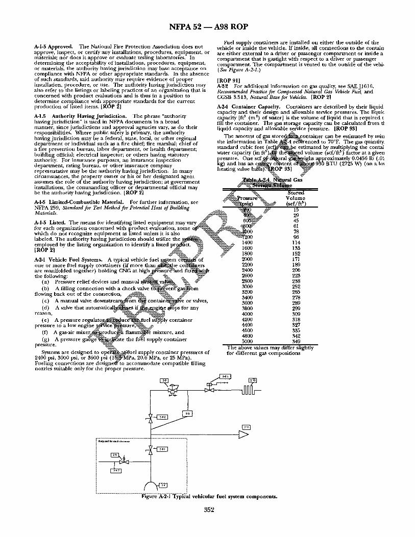
N F P A 5 2 - - A 9 8 R O P
A-I-5 Approved. The National Fire Protection Association does not approve, inspect, or certify any installations, procedures, equipment , or materials; no r does it approve or evaluate testing laboratories. In de te rmin ing the acceptability of installations, procedures, equipment , or materials, the authority having jurisdict ion may base acceptance on compliance with NFPA or o ther appropria te standards. In the absence of such standards, said authority may require evidence of p roper installation, procedure, or use. The authority having jurisdict ion may also refer to the listings or labeling practices of an organization that is concerned with product evaluations and is thus in a position to de te rmine compliance with appropria te standards for the current product ion of listed items. [ROP 2]
A-1.5 Authority Having Jurisdict ion. The phrase "authority having jurisdict ion" is used in NFPA documents in a broad manner , since jurisdict ions and approval agencies vary, as do their responsibilities. Where public safety is primary, the authority having jurisdict ion may be a federal, state, local, or o ther regional depa r tmen t or individual such as a fire chief; fire marshal; chief of a fire prevention bureau, labor depar tment , or heal th depar tment ; building official; electrical inspector; or others having statutory authority. For insurance purposes, an insurance inspection depar tment , rating bureau, or o ther insurance company representative may be the authority having jurisdiction. In many circumstances, the proper ty owner or his or he r designated agent assumes the role of the anthority having jurisdiction; at government
Fuel supply containers are installed on either the outside of the vehicle or inside the vehicle• ff inside, all connect ions to the contain are either external to a driver or passenger compar tment or inside a compa~xnent that is gastight with respect to a driver or passenger compartment . The compar tment is vented to the outside of the vehi~ (See Figure A-2-1.)
[ROP 9 1 1 A-2-2 For additional information on gas quality, see SAEJ1616, Recommended Practice for Compressed Natural Gas Vehicle Fuel and CGSB 3.513, Natural Base for Vehicles. [ROP 2]
A-24 Container Capacity. Containers are descr ibed by their liquid capacity and their design and allowable service pressures• The liquic capacity [ft s (m s) o f water] is the volume of liquid that is required t fill the container. The gas storage capacity can be calculated from tl liquid capacity and allowable service pressure. [ROP 95]
The amount of gas s t o r e ~ . : : c o n t a i n e r can be estimated by usin the information in T a b l e . ~ - 4 r~f@renced to 70°F. The gas quantity. s tandard cubic feet ( s c ~ k b e estimated by multiplying the contai water capacity (in f P ) . ~ th~ ' . ' :~ed volume (scf/f t s ) factor at a given pressure. One scf . . ~ . . ~ r a l ~ ¢ i g h s approximately 0•0456 lb (.01 kg) and has an e ~ d ~ t e ~ o~-"~..~-950 BTU (2725 W) (on a Iox heating va,ue b~',s)'."-~:.pP 9s~ ~
installations, the commanding officer or depar tmental official may be the authority having jurisdiction. [ROP 2] ..4.:'.::" L:~.".:, S tored
: ~i'~:.P ress u r e~'}~.-.-.• V ol um e A-l-5 Limited-Combustible Material. For fur ther information see ~:" "~{~)ii~p.si~r) ":'~:-:-~-~" (scf / f t s) NFPA 259 Standard for Test Method for Potential Heat of Building ":%~"-~ ~5":~ "5 Materials. ...- :.::'.:-":~-~iii ~ :"..!:: " : " ~ . . . . . ""~:"
..-:."~:" . . . . ::!4i~ .... @::::*~" " 6 0 ~ 45 A-I-5 Listed. The means for identifying listed equipment may vary ...-'~i~i( ~,." ~'."~~ for each or nization concerned with roduct evaluation some ~ {,.-'..,-.']~:.:~:.:. .-'-::~0~ -~" 61 • ga . . . . . . , . - : : ~ . . ~ ; . ~ : . . : . , ,. which do no t recogmze equ ipment as ~isted unless ~t ~s also ~.:.:-~:...:....:, ~ 0 0 78
.~ 't200 96 labeled. The authority having jurisdiction should utilize the ~ "~t-:'.:~.-':.-... "~':"" 1400 114 emoloyed by the listing organization to identify a listed prcwl~:~ct. ~:{{i~ ":~..'%':. 4-'.'-
I R ~ P ~! 4~:::'~:':. "-- ~ ~ .-:.": "::!:.-:::~{.~" 1600 133 . . . . . . . 4.~!~:"::~i~{ii.-. . . . . if: ..~!i::"':" 1800 152 A-2-1 Vehicle Fuel Systems. A typical vehicle fuel ¢~tem ~ : : ' o f ':" 2000 171
• " "::'<:~:>" ":':" ; : : : :* 0 0 9 one or more fuel supply contmners (if more t h a n ~ . ~ . l e c o f f ~ e r s 22 18 are manifolded together) holding CNG at high ~ u f ~ a n d f i t / ~ . . . ~ 2400 206 the following: ~>.:'i~i! ~-::- ., :~#'~" 2600 223
(a) Pressure relief devices and manual ~ " ~ r a t a . "%::. -::~ 2800 238 3000 252 (b) A filling connect ion with a check valve t % ~ e ~ : ~ i : g ~ i ~ b m . . . . . .
f i t mg back o t of the connecuon, ::~,..,:...:.,-:?..~@.~-:.~?~::':::~ ":::::::~.".'...,.~.).}~::•..:~.:~-':::" ~ ° . . . . . . z~o (c) A manual valve downstreank:-fi~om ~ c o n t a m ~ . : : ~ e or valves, _~600 9~0 (d) A v a l e that autom t i c a l ~ e s if ~.:.gaagi~..e ~ i p s for any 3800 299
reason, ~':'~" " : ~ ! i " 4000 309 (e) A pressure r e g u l a t o r . . . : ~ l ~ l u c ~ £ u e l s~'~51y container 4200 318
• ~-~'"~ .'- .2;:~.:.-'~i, ressure to a low en ne .~.'rvice .'.~sure,.~:'..-':~:~ ..... 4400 327 p gl ~... ¥ ~ . ~;.<::::...::...::::.. A as- 4600 335 (f) g air mixer. ,~!~roduc~ig f l a m m ' ~ mixture, and . . . . . .
( ) A ressure a0 e"~.:: ~Y~Ttte the filial su I container g P g g .~..::.~ PP Y 5000 349 pressure. ":%i~i~::. The above values may differ slightly
Systems are des igned to ope '~ . . . .~ t 'ue l supply container pressures of for different gas composit ions 2400 psi, 3000 psi, or 3600 psi (I'~.~..~::MPa, 20.6 MPa, or 25 MPa). Fueling connect ions are designedf"to accommodate compatible filling nozzles suitable only for the proper pressure•
• . . . . . . . . . . . . . . . . . . . . . . . . . . . . . . . . . . . . . .
F "
F
F q
~E3
.................................. ~']'~'re"A-2"~]"Ty'p[~al vehicular fuel system components.
3 5 2
N ~ A 5 2 1 A 9 8 R O P
A-2-4.4 Current DOT and TC specifications, exemptions, and specific permits do no t address the use o-f cylinders that are approved for the transportat ion of natural gas to be used in CNG service.
Containers comply ingwi th ANSI/AGA NGV2, Basic Requirements for Compressed Natural Gas Vehicle (NGV) Fuel Containers, are only for use as vehicle fuel containers and require conformance to a gas composi t ion that differs f rom that specified in Section 2-2(a).
Four relevant cylinder inspect ion standards that are useful are Compressed Gas Association publications:
(a) CGA C-6, Standards for Visual Inspection of Steel Compressed Gas Cylinders
(b) CGA C-6.1, Standards for Visual Inspection of High Pressure Aluminum Compressed Gas Cylinders
(c) CGA C-6.2. Guidelines for Visual Inspection and Requalification of Fiber Reinforced Hig~ Pressure Cylinders
(d) CGA C-10, Recommended Procedures for Changes of Gas Service for Compressed Gas Cyli~&rrs.
A-2-5 It is r e c o m m e n d e d that pressure relief devices should be sized to protect ASME pressure vessels against excessive pressure caused by exposure to fire or other sources of external heat, since dais is the worst case condition. As no ted in the ASME Boiler and Pressure Vessel Code, Section VIII, Appendix M, API RP 520, Sizing, Selection, and Installation of Pressure-Relieving Devices in Refineries, Part I, is a reference documen t for sizing of PRDs for fire conditions. Other useful documents include CGA S-I.1, Pressure Relief Device Standards - - Part 1 I Cylinders for Compressed Gases, and CGA S-1.2, Pressure Relief Device Standards - - Part 2 - - Cargo and Portable Tanks for Compressed Gases. .,
Where tank designs are such that heat conduct ion f rom a fire coul.d~ ~ be insufficient to activate a thermally operated pressure relief devicff~.~, the use of heat conduct ion devices or insulating noncombustible.:~'+'":~'~ materials, or both, should be considered (e.g., a ceramic blan~..e...~.,can'~ prevent rupture of a cylinder due to a localized fire). ~ , -
Thermally operated pressure relief devices might no t --.~.~'*:~" " (rate if ~om cylinder is in a tire that is localized and some distance ~.i~.i~.:.,,~.~ -
pressure relief devices. ' . . . . . . It has been demons~ted that a 1-in. ( ~ 5 - m m ) . ~ : ' ~ c ~ ~ n
keep the surface temperature of the container ~ W ~I00~C (392~L~?. "-'~ under fire conditioos for 45 minutes. .-.-:~1 ~" ~")" - '~:'::- ~ # . %-:: %:. ...-.¢:" A-3-1 Fueling Systems. A typical fueling s y s t e ~ ' i ~ f o ~ ¢ o r more compressors taking suction f r o m . ~ u r a l ~ i i ~ m ~ ' ~ n or distribution pipeline or a building pi.~"~*~:en.. ~ co~e.. .~i: : t¢, a transmission or distribution pipeli.~..#.'.:with tl~.~ compre~: '~ : l i scharging into either one or more storage . . . . . ~ e r s : ~ ! ~ : . a ~.la~i tsing system
.. eo s tom oozz,e sometimes, a meter. Where ~.-'.~...~e ..:..~ • . -'~=:"~"":':'::-:.:.:. n e t is'l~resent, it discharges to a dispensing system. ~::~..'.:'" "%.!~ :::~.:.."~-::.~!~......:....~...-:.
w h e r e s t orage ar e the is k n o w n as a "f t- fill" system with a v e h ~ / ? " i ~ . g . . ~ i ~ e of a h t ~ t 3 minutes to 5 minutes. Where storage con,diners ~ t used, the system is known as a "slow- fill" system, and filling times; ~..-'.:....~t .s.everal hours. ',::::::::::~..:.-..--
T h e suction pressure for c o m ' : ~ o r s ranges from approximately 2 psi to 500 psi (13.7 kPa to 3.4 M ~ ) , with the suction pressure for most compressors under 60 psi (40 kPa). The delivery pressure is more than tile vehicle system pressure but less than 5000 psi (35 MPa), with most at approximately 3600 psi (25 MPa).
CNG is s tored ir~ two types of storage systems: bulk storage and cascade storage. They differ in the manner in which the CNG is withdrawn.
A-$-4.1 It is not permit ted to terminate the vent outlet in the engine compar tment . [ROP 2]
A-3-6.5 Electronic fuel injectors are considered to be automatic valves.
A-3-t 2.4
(a) Before a CNG vehicle is re turned to service following an accident that caused damage or dislocation to the CNG fuel system, or following the repair or rep lacement of any part of a CNG fuel system that is subject to container pressure, tile system should be tested in accordance with Section 3-12.
(b) Prior to main tenance or repair of a CNG fuel system, the following should be performed:
1. The supply of CNG should be shut off before commenc ing the work by closing the shutoffvalves and operat ing the engine un t i l t he
engine stops running, and it should be ensured that the valves remai shut off th roughout the inoperative period.
2. CNG should be vented outdoors to a safe location and sho no t be vented indoors.
3. Upon complet ion of the work, the CNG fuel system should leak tested in accordance with the requirements of Section 3-12.
(c) Prior to making repairs to gasoline-related equipment on a CNG vehicle, o ther than to the CNG fuel system, the following shou be performed:
1. The supply of CNG should be shut off pr ior to removal of t natural gas mixer by dos ing the shutoff valves and operating the eng until the engine stops running, and it should be ensured that tile vat remain off th roughout the inoperative period.
2. Upon complet ion q~.~.e work, the natural gas mixer shoul( be placed in its original l ~ ' : " ~ t h o u t any change or adjustment before the CNG s h u t o f f ~ are reopened.
~ % o (d) Prior to m ~ c o l ~ repairs on a CNG vehicle, o ther tt to the CNG fuel ~fim~@..~e f o ) ' l ' ~ n g should be performed:
1. The sh~ to~ .~ , ve at the o~i~'t of the CNG container should be closed before c o r n i c i n g the:~ork, and it should be ensured ti- the valve ~.~'~.-.-.~;fl~.~t~'~hout the inoperative period. . . . . : ~ : . : : - : ~ %
~''Th~':":.'.~.NG v e ~ I ' ~ $ ~ e r or operator should be instructed t tak.¢.....-~ vehici~:~i a vehicle conversion center for inspection of the C N ~ : ' ~ , s y s t e m fi"~..o.r..~:.the shutoff valve described in A-3-12.4(d)1 i r e o
ii" ra~6":~of CNG can be accomplished using one large ~mber of smaller containers manifolded together.
~.:£1~IG from bulk storage, all containers draw down )ressure) at the same rate.
age provides less "available" CNG storage than the casca,
j ~b rage containers ar ranged in a cascade can provide more "~f i lable" CNG storage than a bulk system for the same size containers. A brief description of the operat ion of a typical cascade system is as follows:
A cascade is usually ar ranged in at least three hanks of containers with the containers in any one bank manifolded together so that eacl bank acts as one large container. The banks are separated by autom~ switching valves. The valve sequencing is control led automatically by sequencing control panel.
The cascade banks are initially filled with CNG in sequence by th, compressor to the normal service pressure of the system. The highes pressure bank is refilled first (Bank 1), followed by successively lowe pressure banks (Bank 2, Bank 3, etc~). This sequence is called "prio fill."
Vehicles can then be fueled f rom the cascade, beginning with Bat 3 (for a three-bank cascade).
If there is insufficient CNG in Bank 3 to pressurize tile vehide fue supply container(s) , Bank 3 is valved off a n d Bank 2 "tops up" the vehicle container(s) . Successive vehicles draw f rom Banks 3 and 2, a previously described, until Bank 1 has to "top up" the vehicle container(s) . When Bank 1 pressure is reduced to a preset value, th( compressor bypasses the cascade and fills the vehicle directly. At the complet ion of the last vehicle fill, the compressor continues runnin~ and refills the cascade by priority fill.
Cascade valving can be ar ranged to provide more available storag, than the system described.
CNG can be p roduced f rom liquefied natural gas (LNG). LNG storage containers and equ ipment upstream of CNG containers are 1 covered by dais standard. For information on LNG containers and equipment , see NFPA 57, Standard for Liquefied Natural Gas (LNG) Vehicular Fuel Systems, which is scheduled for adopt ion at the NFPA Fall Meeting in 1995.
A-t-3.3 Methanol injection systems are no t an approved control device. [ROP 63]
A-4-$.9 Aftercoolers and automatic condensate systems frequently a used to remove liquid so that it is no t carried over into the storage system.
A44.3.3 For information on v e n t i n g o f explosions, see NFPA 68, Guide for Venting of Deflagrations. [ROP 2]
353
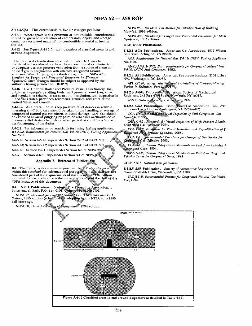
N F P A 5 2 ~ A 9 8 R O P
A-4-4.3.5(b) This co r re sponds to five air changes per hour .
A-4-5.1 Where space is at a p r e m i u m or no t available, cons idera t ion shou ld be given to installat ion o f compressors , dryers, a n d s torage conta iners on a roof m a d e of noncombus t i b l e mater ia l at fue l ing stations.
A-4-12 See Figure A-4.12 for an il lustration of classified areas in and a r o u n d dispensers .
T h e electrical classification specif ied in Table 4.12 may be
~ ermi t ted to be reduced, or haza rdous areas l imited or e l iminated, y adequa te positive pressure vent i la t ion f rom a source of clean air
or iner t gas in con junc t ion with effective safeguards against venti lator failure by purg ing m e t h o d s recognized in NFPA 496, Standard for Purged and Pressurized Enclosures for Electrical
NFPA 259, Standard Test Method for Po¢tmtial Heat of Building Materials, 1993 edition.
NFPA 496, Standard for Purged and Pr,~surized Enclosures for Elect* Equipment, 1993 edition.
B - I . 2 O t h e r P u b l i c a t i o n s .
B-1.2.1 AGA P u b l i c a t i o n s . Amer ican Gas Association, 1515 Wilson Boulevard, Arl ington, VA 22209.
AGA Requirements for Natural Gas Vehicle (NGV) Fueling Appliance. No. 2-90.
ANSI /AGA NGV2, Basic Requirements Jbr Compressed Natural Gas Vehicle (NGV) Fuel Containers, 1992.
B-1.2.2 API Publicat ion. Amer ican Pew0.1eum Institute, 2101 L Stre NW, Wash ing ton , DC 20037.
Equipment. Such changes shou l d be subject to approval by the au thor i ty having jur isdic t ion. [ROP 2] API RP520, Sizing, S d e c t i ~ n d Installation of Pressure-Relieving
Devices in Refineries, Part I~..::Iie39"$:5"-"."ii::.. A-4-16 T h e Un i fo rm Boiler and Pressure Vessel Laws Society, Inc., .,-:.-':'#i'-::. "" publ ishes a synopsis detai l ing boiler a n d pressure vessel laws, rules, B-1.2.3 ASME Publica~'. .(f~i]%i~erican Society of Mechanical a n d regula t ions relat ing to construct ion, installation, a n d inspect ion in Engineers , 345 East . 4 . ~ S t r ~ ' ~ . e w York, NY 10017. the various states provinces terri tories count ies and cities of the . . . . . . . . a{~>" ":i~k .,'~:i.'.::~ii:,, _ . 0 , ~ . . . . . . . "; ~ _ _ ' ' ' ~ o ~ t~otwr a~.':...rres~re vesg~i:~a~.a ~ vz . ut'ntect orates anct Lanana . ~::::-~ii.'... " %'::,:~-::::-'.::-"
. . . . . . *: . . . . ~ . . . . . essure relief dev;c~s in rel a t-'~ 17,-1.2.4 CGA Publ lc~hans . C o m p . ~ : s e d Gas Associat ion Inc. 1725 A 4 1 6 . 4 As ,, v , ~ , . , , , , , , , ~,, " ~ v v " . , . o . ~ - - "~:a:, • .':'." ,,,. ' ' en in a st Je f fe rson Da..vt., Highwayg..,~dmgtot* V A , ~202-4102 opera t ing condi t ion, care shou ld be tak " the h nd l ing or orage of ========================= ......... ~{{:i::.. ' . . . .
compres sed natura l was conta iners to avoid damage . Care also shou ld CGA . . ~ ' 6 ~ { i i ~ ~ { ~ - a u a l Inspection of Steel Compressed Gas be exercised to avo id p lugg ing by pa in t or o the r dir t accumula t ion in Cylin....~.], 199"~".',.'!::, "~-'-"::::~::~:i:i:.:.,..~.% pressure rel ief device channe l s or o ther parts tha t could interfere with o~!k G-6 1 ~ dardsfor Visual lnst~ec'i'on of Hi h Pressure Alumin . . . . ~ . - : . . . . .~. fl ~ , ,J g tile funOaonm~ of file dewce ~ .:::- --::::::::::::.., ~ ~ -P.::,, ~ . . , , o , o • t~ompr~....~...., c, as t~ytt...~..." l~o,*. A-5-2.2 For in format ion on s tandards for listing fuel ing appl iances ........ C G A ' ~ " - ~ G u ~ n e s for Visual Ins~,ection and Re,,ualification ofF;
. . . . ~ .~-:-:-:.:::.:::::-:-. " . .~. . : :~- -~ ..."~-" J " F ~ ~ " ~ / ' see AGA Requirements for Natural Gas gehtcle (~GV) Fuehng Apphancesr;:.?.:.::.:.,:.~.:~:i, forced t~'¢~.: P*',dsure C~linders 1988
.::i::" "~:~J" X~i-:.::i:.¢:::'.'-" ~ :' ' " No. 2-90. . :::.- :.:.. • -..-.: • ,:, ~ .
. ~ .:iiii'}:, .-i~.G A Cq.....1. O,.'..]:~commended Procedures for ~hanges of Gas Servwe for A-6-3.1.1 aec t ion 6-3.1.1 supersedes aect ion 2-5.3 of NFPA 302. -'¢::"%iii]ii.-., ~ i i ~ / ~ Cylinders, 1993. <:::::::~:.:..q~ -::..::::::.:::::.'.::. A-6-3.1.2 Section 6-3.1.2 supersedes Section 4-1.1 of NFPA 302..~..-::.':::.::::.... "-"::.:'ilili!i::.. CGA"I~"I:. 1, Pressure Relief Device Standards - - Part I - - Cylinders J,
A-6-4.1.1 Section 6-4.1.1 supersedes Sect ion 6-3 of NFPA 3..~!::':"" "":'%ili~ "::.-'~......pf~sed Gases, 1994. ,.':!:-::: :?~iii" "::~." "~-_,A S-1.2, Pressure Relief Device Standa:rds - - Part 2 - - Cargo and
P~able Tanks for Compressed Gases, 1994. A-6-5.1 Section A-6-5.1 supersedes Section 3-1 of NF P A_ . -~ .~ .,<ii:: " . . . . -~i-i-~:.-.: . , ~
Append ix B R e fe r enced Publica..t .i~. ":~]!{~ii: .-.':i::" .... <:',q: ":-'~:i:':~:i::., x-.
B-1 The following d o c u m e n t s or por t ions the~....:.'~of ar:g reference8~{i{iiii!i !'::" within dais s t anda rd for informat ional p u r p ~ i i ~ l y ~ thd~....are.vd:~St cons idered par t o f the r equ i r emen t s o f dais ~ l o ~ . 0 ~ ' f f * / i e e~...~on indicated for each re ference is the curre.o&c.dition"~.~::'..~.f the d.@i."~ of the NFPA issuance o f dais d o c u m e n t , x:.:i.-"i--~:?i::ii::ii::~:: %{::]i:":"::, ..#'"
B-I.I NFPA P u b l i c a t i o n s . Nat iq l~i .F i re P:Y.::g.tg.etio R. ~ : c i a t i o n , 1 Bat terymarch Park, P.O. Box 9 1 ~ - ' l : ' : " ~ . ~ i ~ i ~ g ~ - O ] 0 1 .
NFPA 57, Standard for Li~: .: .Nat~' t . : i : :Gas (]~:~) Vehicular Fuel Systems, 1995 edi t ion (sch.....t~li]'4~'~ a d 0 ~ b.~. the NFPA at its 1995 Fall Meet ing) . ~::~ii~i~i.. i~ii:: i: '~!]i~':':::"
NFPA 68, G u i d e f o C ~ : o ~ . . ~ f l a g r a t i o ~ : [ 1 9 9 4 edition.
CGSB 3.513, Natural Base for Vehicles
B-1.2.5 SAE P u b l i c a t i o n . Society of Automot ive Engineers , 400 C o m m o n w e a l t h Drive, Warrenda le , PA 15096.
SAEJ1616, Recommended Practice for C~unpressed Natural Gas Vehicle Fue/, 1994.
.::':::
Disp~s~ ~
F i g u r e A 4 - 1 2 C l a s s i f i e d a r e a s i n a n d a r o u n d d i s p e n s e r s a s d e t a i l e d i n T a b l e 4-12.
3 5 4