Embed Size (px)
Citation preview
8/4/2019 Report Shafi
http://slidepdf.com/reader/full/report-shafi 1/17
Seminar 2011 Zigbee electric vehicle
identification and charging system
Chapter 1
INTRODUCTION
Along with to the growth of the number of private car, it increases
the toxic chemicals released and the need of fossil fuel. These toxic
chemicals probability causes Greenhouse effect and respiratory disease
which is harmful to both human being and environment. To improve the
situation, electric vehicles published as a replacement. And there are
several new infrastructure published to act in concert. With the increasing number
of electric cars usage, management of the power consumption of the electric cars becomes
another important issue. People are willing to pay more attention on how many power is
consumed. So, it will be an essential for a platform which enables data exchange
between automobile owner, Utility information systems (e.g. MDMS, billing) and the
Charging Hotspot subsystem.
ZED is an AMI solution dedicated to electrical vehicle charging for both private and
public car parks. ZED is divided into two main parts: onsite subsystem (Charging Hotspot)
and backend subsystem (i-Plug). Charging Hotspot subsystem consists of Z-key, Z-Charger
and Data Hub which server the Electric Vehicle (EV) owners at the car park. Z-Key is a
handheld device for users to initialize the charging process. Z Charger is outlet adopting
latest short range communication ZigBee that measures the energy consumption during the
charging process. The Data Hub collects the readings from the Z-Charger and forwards the
data to i-Plug. i-Plug is a platform enables data exchange between EV owner, Utility
information systems (e.g. MDMS, billing) and the Charging Hot spot Sub system. Finally,
the EV owner could obtain the latest charging information via the web portal of i-Plug.
Department of Electronics and communicatioin 1
Y.C.E.T, KOLLAM
8/4/2019 Report Shafi
http://slidepdf.com/reader/full/report-shafi 2/17
Seminar 2011 Zigbee electric vehicle
identification and charging system
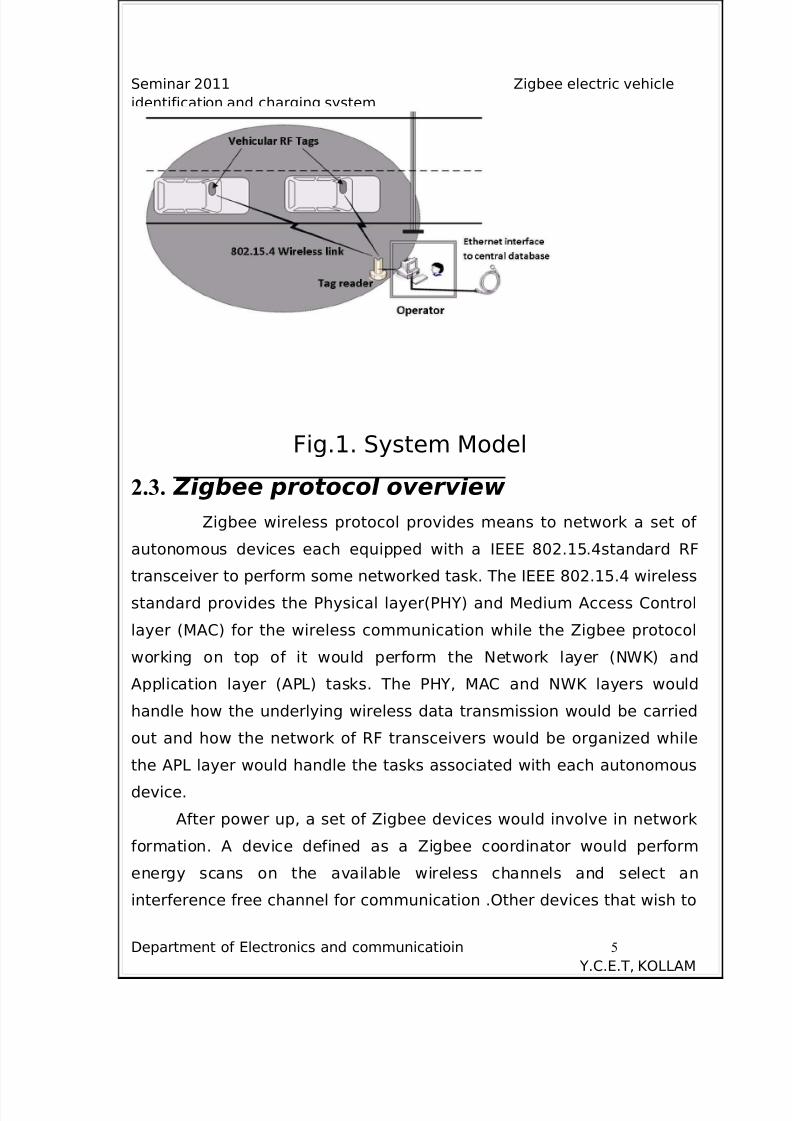
The Vehicle identification system using Zigbee wireless RF tags to
identify and authenticate vehicles entering into premises. It consists of RF vehicle tags containing authentication information for each vehicle
authorized, an RF tag reader, an RF tag writer and a central database
containing information about all vehicles authorized to enter the facility.
Vehicular RF Tags are installed securely in all vehicles needed to be
identified,
authenticated and managed.
Department of Electronics and communicatioin 2
Y.C.E.T, KOLLAM
8/4/2019 Report Shafi
http://slidepdf.com/reader/full/report-shafi 3/17
Seminar 2011 Zigbee electric vehicle
identification and charging system
Chapter 2
VEHICULAR IDENTIFICATION AND
AUTHENTICATION SYSTEM
Vehicular RF Tags are installed securely in all vehicles needed to
be identified , authenticated and managed. Each vehicular RF tag is
programmed to have a unique serial number for identifying it and a
password to authenticate the driver. An RF tag reader module is
installed near the entrance to the facility. When a vehicle stops at the
entrance the reader detects the vehicular RF tag and retrieves
authentication information from it. This information is transfered over
Ethernet to a central database to verify whether access is granted for a
particular vehicle to enter into premises. Furthermore, the driver of the
vehicle is authenticated by means of a password entered using a
numerical keypad in the vehicular RF tag when prompted by the RF tag
reader. Using the information received from the central database a
human security personnel at the entrance or automated security system
can take action to allow or deny the vehicle entrance into the facility.
2.1. Vehicular RF Tag
Each vehicle would be equipped with a vehicular RF tag having a
unique serial number. The vehicular RF tag module would consists of a
2.4 GHz RF transceiver, microcontroller circuitry, power control circuitry,
Department of Electronics and communicatioin 3
Y.C.E.T, KOLLAM
8/4/2019 Report Shafi
http://slidepdf.com/reader/full/report-shafi 4/17
Seminar 2011 Zigbee electric vehicle
identification and charging system
LED indicators and a numerical keypad used to enter password for driver
authentication.
2.2. RF Tag Reader, Writer The vehicular RF tag reader and writer are implemented as one unit.
It comprises of a 2.4 GHz wireless transceiver , micro-controller, power
control circuitry, and a debugging
and communication interface. This module is connected to a personal
computing device (laptop or desktop) through aRS232 interface which is
used by the security personnel at
the entrance. Communication from there onwards to central database
server is done through Ethernet. Depending on the verification sent by
the database server, positive or negative , the user at the entrance is
presented with the simple decision of whether to allow or deny entrance
to a vehicle or to check the identification of vehicle and authentication
of a driver manually by engagement if in doubt. Although the human
agent in the system between the central database and the tag reader
can be removed and the system can be fully automated, we have
resorted to implement it with human involvement since most
organizations employ security personnel. The RF tag writer is used to
program the unique vehicle serial number and password information into
a vehicular RF tag.
Department of Electronics and communicatioin 4
Y.C.E.T, KOLLAM
8/4/2019 Report Shafi
http://slidepdf.com/reader/full/report-shafi 5/17
Seminar 2011 Zigbee electric vehicle
identification and charging system
Fig.1. System Model
2.3. Zigbee protocol overview
Zigbee wireless protocol provides means to network a set of
autonomous devices each equipped with a IEEE 802.15.4standard RF
transceiver to perform some networked task. The IEEE 802.15.4 wireless
standard provides the Physical layer(PHY) and Medium Access Control
layer (MAC) for the wireless communication while the Zigbee protocol
working on top of it would perform the Network layer (NWK) and
Application layer (APL) tasks. The PHY, MAC and NWK layers would
handle how the underlying wireless data transmission would be carried
out and how the network of RF transceivers would be organized while
the APL layer would handle the tasks associated with each autonomous
device.
After power up, a set of Zigbee devices would involve in network
formation. A device defined as a Zigbee coordinator would perform
energy scans on the available wireless channels and select an
interference free channel for communication .Other devices that wish to
Department of Electronics and communicatioin 5
Y.C.E.T, KOLLAM
8/4/2019 Report Shafi
http://slidepdf.com/reader/full/report-shafi 6/17
Seminar 2011 Zigbee electric vehicle
identification and charging system
join the network would send out beacon requests in order to join the
network of the coordinator .The newly joined child devices to the
network can either work as end devices or routers where the coordinator
is the parent . Routers can permit other devices to join it where a end
devices can’t; i.e. they are leaf nodes of the network.
In the proposed system a vehicular RF tag takes the role of a
Zigbee end device while the tag reader & writer module takes the role of
Zigbee coordinator. Different Zigbee devices implement different device
profiles defined under the Zigbee protocol stack to suit the application in
which they are being used. The Zigbee alliance has defined several
device profiles for typical applications intended for Zigbee devices, such
as home and building automation, industrial control etc . The
specification has also provided flexibility to include custom device
profiles to suit customized applications .We have defined the vehicle
identification device profile to suit our application as shown in Fig. 2.
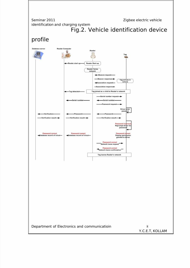
2.4. Tag-Reader communication
Fig. 3 shows the sequence of steps involved in the communication
between vehicular Tag and Tag reader. Once a tagged vehicle arrives
into the vicinity of the RF tag reader the
vehicular RF tag would issue beacon requests to the Tag reader .Tag
reader would respond with beacon response and join the RF tag into its
network as a child node. Once connected to the personal area network
(PAN) of the Tag reader, it would request the vehicle serial number from
the tag. After reception of the serial number from the tag the password
for driver authentication is requested by the reader which is validated
with the central database once received from the tag. After both serial
number and password are successfully
Department of Electronics and communicatioin 6
Y.C.E.T, KOLLAM
8/4/2019 Report Shafi
http://slidepdf.com/reader/full/report-shafi 7/17
Seminar 2011 Zigbee electric vehicle
identification and charging system
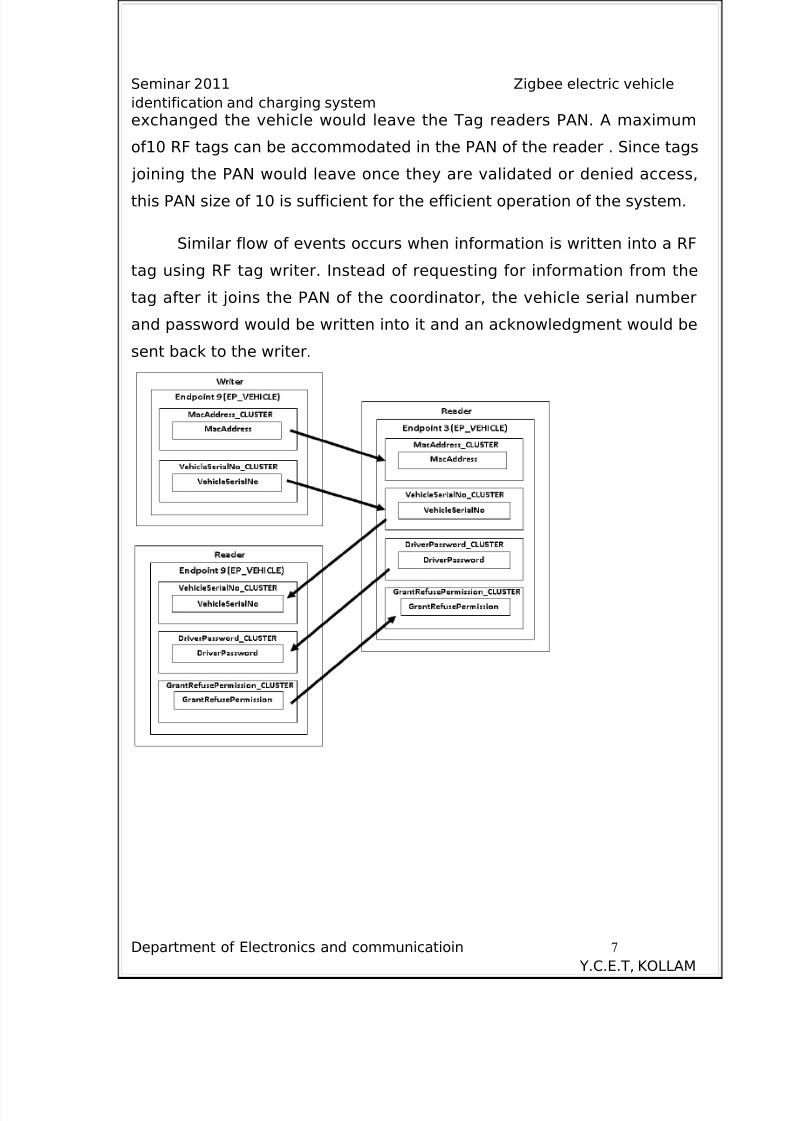
exchanged the vehicle would leave the Tag readers PAN. A maximum
of10 RF tags can be accommodated in the PAN of the reader . Since tags
joining the PAN would leave once they are validated or denied access,
this PAN size of 10 is sufficient for the efficient operation of the system.
Similar flow of events occurs when information is written into a RF
tag using RF tag writer. Instead of requesting for information from the
tag after it joins the PAN of the coordinator, the vehicle serial number
and password would be written into it and an acknowledgment would be
sent back to the writer.
Department of Electronics and communicatioin 7
Y.C.E.T, KOLLAM
8/4/2019 Report Shafi
http://slidepdf.com/reader/full/report-shafi 8/17
Seminar 2011 Zigbee electric vehicle
identification and charging system
Fig.2. Vehicle identification device
profile
Department of Electronics and communicatioin 8
Y.C.E.T, KOLLAM
8/4/2019 Report Shafi
http://slidepdf.com/reader/full/report-shafi 9/17
Seminar 2011 Zigbee electric vehicle
identification and charging system
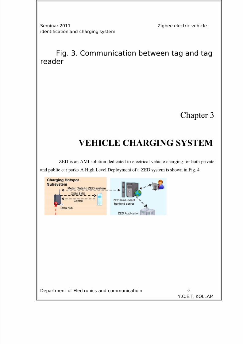
Fig. 3. Communication between tag and tag
reader
Chapter 3
VEHICLE CHARGING SYSTEM
ZED is an AMI solution dedicated to electrical vehicle charging for both private
and public car parks. A High Level Deployment of a ZED system is shown in Fig. 4.
Department of Electronics and communicatioin 9
Y.C.E.T, KOLLAM
8/4/2019 Report Shafi
http://slidepdf.com/reader/full/report-shafi 10/17
Seminar 2011 Zigbee electric vehicle
identification and charging system
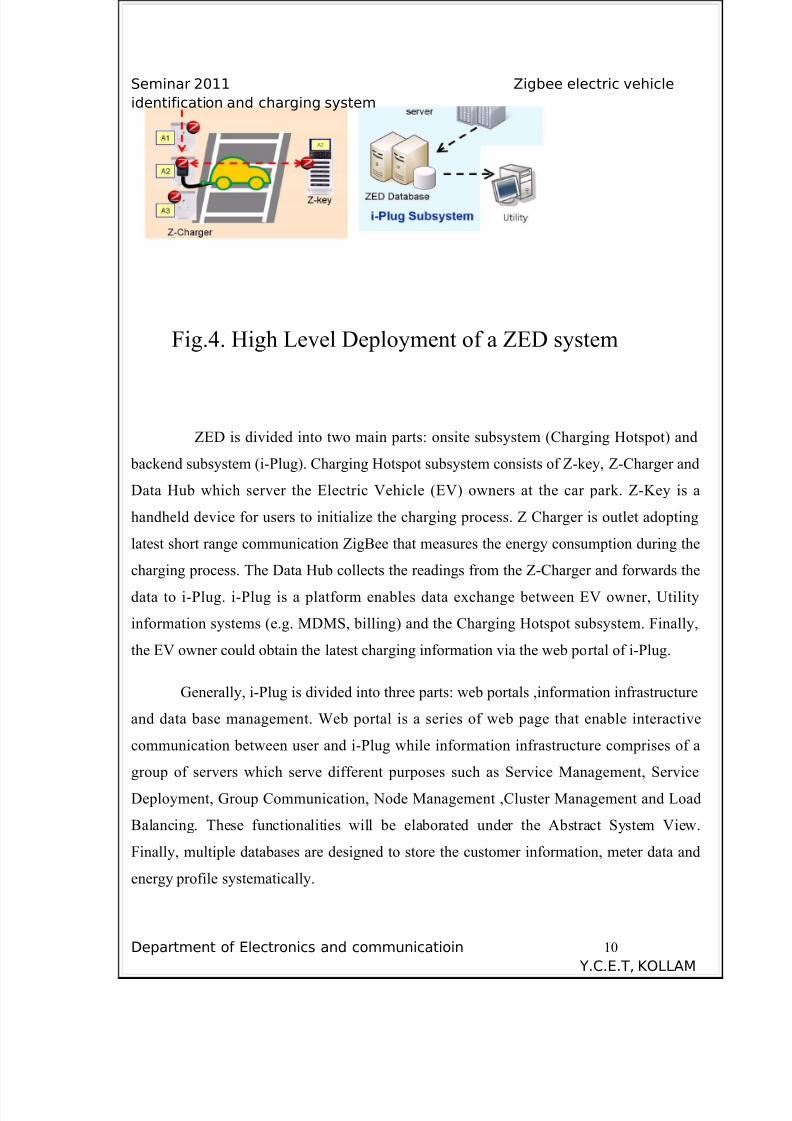
Fig.4. High Level Deployment of a ZED system
ZED is divided into two main parts: onsite subsystem (Charging Hotspot) and
backend subsystem (i-Plug). Charging Hotspot subsystem consists of Z-key, Z-Charger and
Data Hub which server the Electric Vehicle (EV) owners at the car park. Z-Key is a
handheld device for users to initialize the charging process. Z Charger is outlet adopting
latest short range communication ZigBee that measures the energy consumption during the
charging process. The Data Hub collects the readings from the Z-Charger and forwards the
data to i-Plug. i-Plug is a platform enables data exchange between EV owner, Utility
information systems (e.g. MDMS, billing) and the Charging Hotspot subsystem. Finally,
the EV owner could obtain the latest charging information via the web portal of i-Plug.
Generally, i-Plug is divided into three parts: web portals ,information infrastructure
and data base management. Web portal is a series of web page that enable interactive
communication between user and i-Plug while information infrastructure comprises of a
group of servers which serve different purposes such as Service Management, Service
Deployment, Group Communication, Node Management ,Cluster Management and Load
Balancing. These functionalities will be elaborated under the Abstract System View.
Finally, multiple databases are designed to store the customer information, meter data and
energy profile systematically.
Department of Electronics and communicatioin 10
Y.C.E.T, KOLLAM
8/4/2019 Report Shafi
http://slidepdf.com/reader/full/report-shafi 11/17
Seminar 2011 Zigbee electric vehicle
identification and charging system
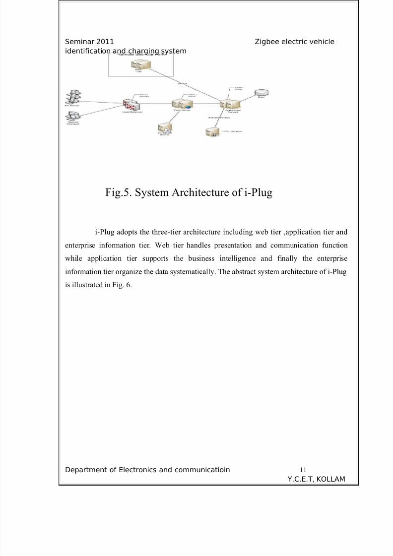
Fig.5. System Architecture of i-Plug
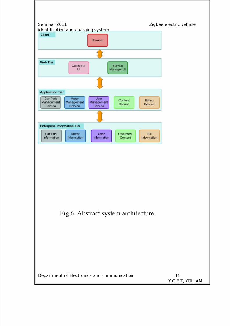
i-Plug adopts the three-tier architecture including web tier ,application tier and
enterprise information tier. Web tier handles presentation and communication function
while application tier supports the business intelligence and finally the enterprise
information tier organize the data systematically. The abstract system architecture of i-Plug
is illustrated in Fig. 6.
Department of Electronics and communicatioin 11
Y.C.E.T, KOLLAM
8/4/2019 Report Shafi
http://slidepdf.com/reader/full/report-shafi 12/17
Seminar 2011 Zigbee electric vehicle
identification and charging system
Fig.6. Abstract system architecture
Department of Electronics and communicatioin 12
Y.C.E.T, KOLLAM
8/4/2019 Report Shafi
http://slidepdf.com/reader/full/report-shafi 13/17
Seminar 2011 Zigbee electric vehicle
identification and charging system
3.1. IMPLEMENTATION
i-Plug could be broken down into five subsystems: Car Park Management (CPM)
subsystem, Meter Management (MM)subsystem, User Management (UM) subsystem,
Content Service (CS) subsystem and Billing Service (BS) Subsystem ,and each of them
serves clients in different purposes.
3.1.1. Car Park Management (CPM) subsystem
This subsystem handles the information of car park and it contains two major
components Car Park Management Service module and Car Park Information database.
CPM subsystem helps the service manager (Utility employee)managing the information of
car park and so the EV owner could the obtains the updated information via the portal.
3.1.2. Meter Management (MM) subsystem
This subsystem handles the information of meter and It contains two major
components Meter Management Service module and Meter Information database. MMsubsystem collects meter reading and status from Charging Hotspot system and so the
service manager and EV owner could obtain the energy consumption information though
their web portals .Furthermore, this subsystem monitors the status of the meter and
generates meter error report automatically if any operation failure is detected. Such report
will deliver to service manager via email and also the warning message will display on the
web portal.
3.1.3. User Management (UM) subsystem
This subsystem handles the information of user and it contains two major components User
Management Service module and User Information database. UM subsystem identifies the
role of user and helps the service manger managing the EV owner information easily.
Department of Electronics and communicatioin 13
Y.C.E.T, KOLLAM
8/4/2019 Report Shafi
http://slidepdf.com/reader/full/report-shafi 14/17
Seminar 2011 Zigbee electric vehicle
identification and charging system
3.1.4. Content Service (CS) subsystem
This subsystem handles the information of user and it contains two major components
Content Service module and Document database. CS subsystem generates reports and
documents and it allows Utility information system obtaining the document via predefined
communication interface such as active directory.
3.1.5. Billing Service (BS) Subsystem
This subsystem handles the billing information and it contains two major components
Billing Service module and Bill Information database. BS subsystem cooperates with MM
and CS subsystem in order to generate the most updated payment record.
Department of Electronics and communicatioin 14
Y.C.E.T, KOLLAM
8/4/2019 Report Shafi
http://slidepdf.com/reader/full/report-shafi 15/17
Seminar 2011 Zigbee electric vehicle
identification and charging system
Chapter 4
ADVANTAGES
When the electrical vehicle owners login the i-Plug web portal, the owners get the
latest news from the welcome page ,the current status and the last charging record are also
displayed. Users are allowed to check the current charge info and their current and previous
monthly bills. They can also view the monthly and yearly energy consumption by different
time and different locations. The total energy consumption is plotted by different chart type
chosen by users. If the user want to locate the car parks which provide EV Charger ,the
user can search the car park through the map in the i-Plug web portal. The numbers of
available chargers in the car parks shown are real time. The owner can sort the car park
results by price, and time.
Department of Electronics and communicatioin 15
Y.C.E.T, KOLLAM
8/4/2019 Report Shafi
http://slidepdf.com/reader/full/report-shafi 16/17
Seminar 2011 Zigbee electric vehicle
identification and charging system
Chapter 5
CONCLUSION
In this paper , novel Zigbee based vehicular identification , authentication
system and Zigbee based EV charging system are presented .This paper discussed about
Zigbee Energy Dispenser , it is a new platform which coordinates the data flow among
customer, utility information system and charging hot spot. The usage and architecture are
briefly introduced, And the advantages are also discussed.
Department of Electronics and communicatioin 16
Y.C.E.T, KOLLAM
8/4/2019 Report Shafi
http://slidepdf.com/reader/full/report-shafi 17/17
Seminar 2011 Zigbee electric vehicle
identification and charging system
REFERENCES
[1] K. L. Lam, K. T. Ko, H. Y. Tung, H. C. Tung, K. F. Tsang and L. L. Lai ,
“ZigBee Electric Vehicle Charging System”. IEEE International
Conference on Consumer Electronics, pp.507-508, 2011.
[2] S. D. Dissanayake, P. P. C. R. Karunasekara, “Zigbee Wireless
Vehicular Identification and Authentication System,” IEEE , pp.
257–260, 2008.
[3] Stanton W. Hadley, “Impact of Plug-in Hybrid Vehicles on the
Electric Grid”, ORNL Report, Oct 2006.
[4] ZigBee Alliance, ZigBee Specifications, version 1.0, April 2005.
[5] A. Wheeler, “Commercial applications of wireless sensor networks using zigbee,” in Communications Magazine, IEEE ,
vol. 45, no. 4, Apr. 2007, pp. 70–77.
Department of Electronics and communicatioin 17
Y C E T KOLLAM