Embed Size (px)
Citation preview
Research ArticleCyclical Behavior of Concrete-Encased Composite FrameJoints with High Strength Concrete
Lei Zeng, Zhenkun Cui, Yunfeng Xiao, Siqian Jin, and Yuanyuan Wu
School of Urban Construction, Yangtze University, Jingzhou 434023, China
Correspondence should be addressed to Lei Zeng; [email protected]
Received 28 April 2015; Accepted 2 July 2015
Academic Editor: Stefano Sorace
Copyright © 2015 Lei Zeng et al.This is an open access article distributed under the Creative Commons Attribution License, whichpermits unrestricted use, distribution, and reproduction in any medium, provided the original work is properly cited.
This paper presents an application of high strength concrete to concrete-encased composite frame building based on anexperimental program. The work emphasized joints behavior under reverse cyclic loading caused by earthquakes to provideinformation for seismic design. To investigate the internal mechanisms and seismic performance, cyclic loading tests were carriedout on five half-scale interior joints. Two design variables were addressed in the research: concrete strength and axial column load.Frame joints performance including crack pattern, failure mode, deformation, ductility, strain distribution, and energy dissipationcapacity was investigated. It was found that all joint specimens behaved in a manner with joint panel shear failure. Using highstrength concrete increased the joint strength and had relatively little effect on the stiffness and ductility. The axial column loadhelped the joint strength by better mobilizing the outer part of the joint, but it had an obvious influence on the ductility andenergy-dissipating capacity, which can be improved by providing enough transverse reinforcement. A typical crack pattern was alsoprovidedwhich canwell reflectmechanical character and damage process.This research should contribute to the future engineeringapplications of high strength concrete to concrete-encased composite structure.
1. Introduction
Concrete-encased composite structure, as a typical kind ofcomposite structure, is defined as a construction in whichboth steel and concrete materials are effectively combinedto maximize the structural and economic advantages ofeach material. Concrete-encased composite structure pos-sesses a smaller sectional dimension, higher load-carryingcapacity, andmore excellent seismic behavior compared withreinforced concrete structures, which has been widely usedin superhigh building structures and large-span structuresespecially in the US [1], China [2], and Japan [3].
Over the past years, various innovations have been devel-oped for concrete-encased composite structure. One cleartrend has been the increased use of concrete material withhigh strength and high performance [4–8]. The introductionof high strength concrete solved a lot of problems in securityand endurance because of its high strength, high modulus ofelasticity, good endurance, and excellent abrasion resistance,but brittleness hinders its application to engineering struc-tures [9–12].
One important research need aroused by the highstrength concrete relates to beam-column joints. Jointsbetween beams and columns are potentially the most criticaland possibly the least understood parts of the structuralframe. Several elements of the structure meet at a joint, andthe combination results in a complex behavior that the joint isat a multiple spindle stress condition under the interaction ofbending, shear, and axial loads by adjacent members. Manyexperiments have been carried out to study the strengthand deformation and provide data for developing designequations.The related experiments include concrete-encasedsteel composite beam to steel column joints [13], compositebeam to concrete-filled steel tubular column joints [14],reinforced concrete beam-column joints strengthened withFRP systems [15], beam-column joints with recycled concreteaggregates [16], and steel reinforced concrete column-steeltruss beam hybrid joints [17]. Based on the experimentalresults, design guidelines for composite construction areprovided in theACI code [18], the AISC specification [19], theJGJ specification [20], and the AIJ-SRC code [21]. However,
Hindawi Publishing CorporationAdvances in Materials Science and EngineeringVolume 2015, Article ID 873162, 13 pageshttp://dx.doi.org/10.1155/2015/873162
2 Advances in Materials Science and Engineering
a better understanding of the joint behavior has not been yetachieved because of the inherent complexity of the internalmechanisms. In particular, influences of various factors onthe joint behavior, such as different joint details, concretestrength, and axial column load, have also been suggested asfurther research topics. In addition, high strength concretepossesses brittleness and differs with normal concrete inmaterials,mix proportions, production technology, and bondperformance. The influences on joint behavior and corre-sponding countermeasures have been the important issues tobe further studied.
This paper presents an experimental program on thebehavior of composite joints with high strength concrete,under constant axial column compression and cyclic loads.The work emphasizes the joint behavior under reverse cyclicloading caused by earthquake to provide information forseismic design.The effects of high strength concrete and axialcolumn load are studied through the following items: failurepattern, crack pattern, load-displacement curves, strain dis-tribution, ductility capacity, and energy dissipation capacity.These results can be used to calibrate numerical models andto validate simplified methods included in codes.
2. Experimental Program
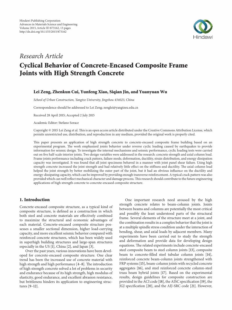
2.1. Test Specimens. This research program involved the test-ing of five interior half-scale beam-column joint specimens.Theprototypeswere taken froma typical component betweenthe inflection points in a concrete-encased frame structure(see Figure 1). All specimens were designed to fail withinits joints. The geometric and the cross section details ofthe specimens were designed (see Figure 2). The columnand beam section dimensions of all specimens were 240 ×200mm and 160 × 280mm, respectively.
The experimental program is designed to investigate thefollowing variables that may affect the strength, deformation,and seismic performance of the joints (see Table 1).(1)The design axial column load ratio is (𝑛 = 𝑁/𝑓
𝑐𝑏ℎ),
where 𝑁 was the axial load applied, 𝑏 and ℎ were the widthand depth of the cross section, and 𝑓
𝑐refers to compressive
strength of concrete. The nominal axial column load ratio isalso calculated by 𝑛
0= 𝑁/(𝐴
𝑐+𝛼𝐸𝐴𝑠), where𝐴
𝑐and𝐴
𝑠were
the area of concrete and steel section and 𝛼𝐸was the ratio of
modulus of elasticity of steel and concrete.Specimens J-1 and J-2 were tested with axial compression
load of 750 kN and 1500 kN, which corresponds to about20% to 40% of design compressive strength of the concrete-encased column. The magnitude represents a reasonableworking compressive stress level for typical structures. Spec-imens J-3, J-4, and J-5 were tested with axial compressionload of 2250 kN, 2750 kN, and 2750 kN, which represents anultimate compressive stress level.(2) An important factor concerned in design is the
brittle nature of high strength concrete compared to ordinarystrength concrete. High strength concrete, with a strengthranging from 79.82MPa to 109.54MPa, has been used toinvestigate the influence on deformation capacity and seismicresistance of joints.
Table 1: Design parameter of beam-column assemblies.
Parameter J-1 J-2 J-3 J-4 J-5Concrete strength grade C80 C80 C80 C100 C60Design axial compression ratio 0.2 0.4 0.6 0.6 0.6Nominal axial compression ratio 0.19 0.38 0.56 0.52 0.55Axial compression load (kN) 75 150 225 275 275
2740 2740
1780
1780
Figure 1: Description of prototype model.
2.2. Material Property. The proportions of different mixingsubstances in the concrete were determined based on theinformation available from JGJ/T 281-2012 (see Table 2) [22].To improve theworkability, a superplasticizer wasmixedwiththe concrete.Themaximum size of coarse aggregate is 13mm,which was tiny enough to place concrete into the congestedjoint region.
All specimens were tested at 28 days. Three cylinders(150 × 300mm)were tested to determine the average concreteaxial compressive strength and modulus of elasticity for eachspecimen, and three cubes (150 × 150 × 150mm) were testedto determine the average concrete cube compressive strength.Thus, the concrete properties were measured (see Table 2).
The encased structural steel used in the specimens wasI-shaped hot-rolled structural steel. The longitudinal barused was 12mm in diameter and deformation. Deformationbars of 8mm in diameter were used as hoop reinforcement.To determine the average values of the steel mechanicalproperties, three pieces were tested following GB/T 228.1-2010 for each one [23].The results of the characterization testsare shown in Table 3.
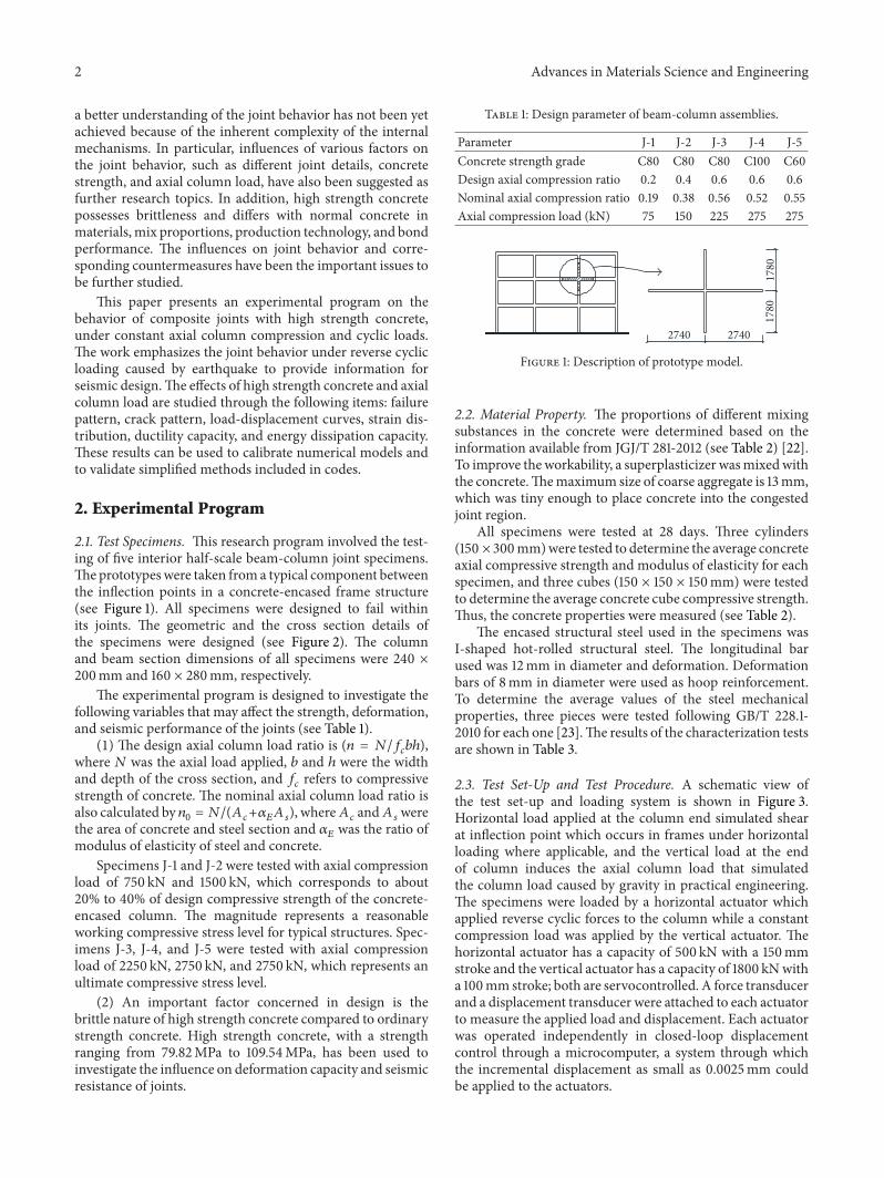
2.3. Test Set-Up and Test Procedure. A schematic view ofthe test set-up and loading system is shown in Figure 3.Horizontal load applied at the column end simulated shearat inflection point which occurs in frames under horizontalloading where applicable, and the vertical load at the endof column induces the axial column load that simulatedthe column load caused by gravity in practical engineering.The specimens were loaded by a horizontal actuator whichapplied reverse cyclic forces to the column while a constantcompression load was applied by the vertical actuator. Thehorizontal actuator has a capacity of 500 kN with a 150mmstroke and the vertical actuator has a capacity of 1800 kNwitha 100mm stroke; both are servocontrolled. A force transducerand a displacement transducer were attached to each actuatorto measure the applied load and displacement. Each actuatorwas operated independently in closed-loop displacementcontrol through a microcomputer, a system through whichthe incremental displacement as small as 0.0025mm couldbe applied to the actuators.
Advances in Materials Science and Engineering 3
750
800
2
1
160
280
240
200
280
1
112
2
2
1250 1250240
I14
I14
2-2
1-1
30 × 4
60 × 18
60×10
60×10
30×3
30×3
Φ8
Φ8
2Φ12
2Φ12
2Φ12
2Φ12
Figure 2: Cross section and distributed steel of beam-column assemblies.
Table 2: Concrete mix properties and strength.
Design strengthgrade C60 C80 C100
Water cementitiousratio 0.30 0.26 0.24
Cement (kg/m3) 350 450 450Coarse aggregate(kg/m3) 700 544 510
Fine aggregate(kg/m3) 1150 1156 1190
Water (kg/m3) 150 156 144Superplasticizer(kg/m3) 8 12 12
Silica fume (kg/m3) 0 30 60Fly ash (kg/m3) 150 120 90Cube compressivestrength (MPa) 79.82 87.89 109.54
Axial compressivestrength (MPa) 68.25 78.49 95.07
Modulus ofelasticity (MPa) 41675 42042 42885
Table 3: Materials properties of bars and steel plate.
MaterialYieldingstrength(MPa)
Yieldingstrain
Ultimatestrength(MPa)
Ultimatestrain
Elasticmodulus(GPa)
Φ8 bar 360 1.71 × 10⁻³ 440 2.43 × 10⁻³ 210Φ12 bar 380 1.81 × 10⁻³ 490 2.65 × 10⁻³ 210Steelplate 317 1.51 × 10⁻³ 420 2.26 × 10⁻³ 210
According to the loading program, column axial columnload was first applied, and then horizontal cyclic load wasapplied step by step to the estimated yielding load. Because
SupportSupport
Transducer
SpecimenActuator
Actuator
Figure 3: Test set-up and loading system.
specimen J-1 was the first one, small load increment in loadcontrol stage was given. The other specimens were loaded tothe yielding load in 4 to 6 steps. The last load step circulatedfor three cycles, current column end deformation was taken
4 Advances in Materials Science and Engineering
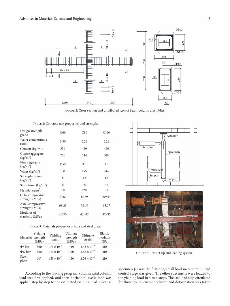
(a) Concrete cracking on beam (b) Cracking on panel core zone
Figure 4: Experimental phenomenon in elastic stage.
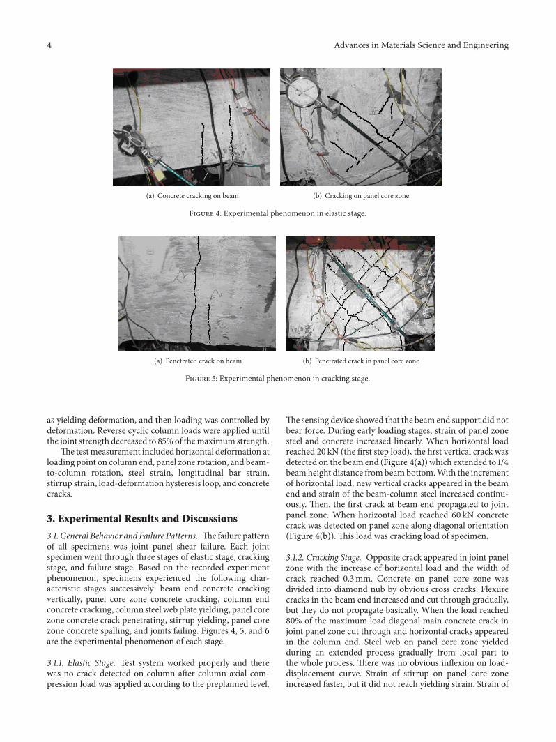
(a) Penetrated crack on beam (b) Penetrated crack in panel core zone
Figure 5: Experimental phenomenon in cracking stage.
as yielding deformation, and then loading was controlled bydeformation. Reverse cyclic column loads were applied untilthe joint strength decreased to 85%of themaximum strength.
The testmeasurement included horizontal deformation atloading point on column end, panel zone rotation, and beam-to-column rotation, steel strain, longitudinal bar strain,stirrup strain, load-deformation hysteresis loop, and concretecracks.
3. Experimental Results and Discussions
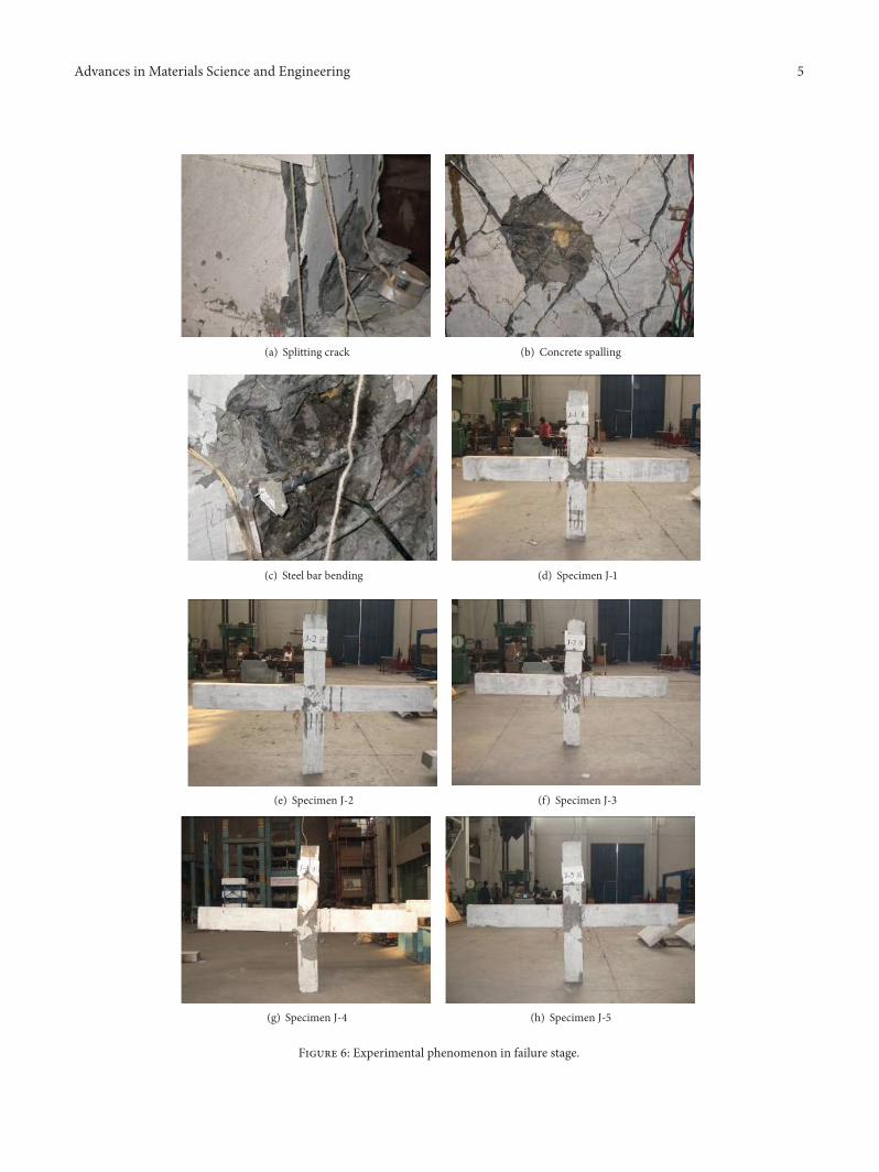
3.1. General Behavior and Failure Patterns. Thefailure patternof all specimens was joint panel shear failure. Each jointspecimen went through three stages of elastic stage, crackingstage, and failure stage. Based on the recorded experimentphenomenon, specimens experienced the following char-acteristic stages successively: beam end concrete crackingvertically, panel core zone concrete cracking, column endconcrete cracking, column steel web plate yielding, panel corezone concrete crack penetrating, stirrup yielding, panel corezone concrete spalling, and joints failing. Figures 4, 5, and 6are the experimental phenomenon of each stage.
3.1.1. Elastic Stage. Test system worked properly and therewas no crack detected on column after column axial com-pression load was applied according to the preplanned level.
The sensing device showed that the beam end support did notbear force. During early loading stages, strain of panel zonesteel and concrete increased linearly. When horizontal loadreached 20 kN (the first step load), the first vertical crack wasdetected on the beam end (Figure 4(a)) which extended to 1/4beamheight distance frombeambottom.With the incrementof horizontal load, new vertical cracks appeared in the beamend and strain of the beam-column steel increased continu-ously. Then, the first crack at beam end propagated to jointpanel zone. When horizontal load reached 60 kN concretecrack was detected on panel zone along diagonal orientation(Figure 4(b)). This load was cracking load of specimen.
3.1.2. Cracking Stage. Opposite crack appeared in joint panelzone with the increase of horizontal load and the width ofcrack reached 0.3mm. Concrete on panel core zone wasdivided into diamond nub by obvious cross cracks. Flexurecracks in the beam end increased and cut through gradually,but they do not propagate basically. When the load reached80% of the maximum load diagonal main concrete crack injoint panel zone cut through and horizontal cracks appearedin the column end. Steel web on panel core zone yieldedduring an extended process gradually from local part tothe whole process. There was no obvious inflexion on load-displacement curve. Strain of stirrup on panel core zoneincreased faster, but it did not reach yielding strain. Strain of
Advances in Materials Science and Engineering 5
(a) Splitting crack (b) Concrete spalling
(c) Steel bar bending (d) Specimen J-1
(e) Specimen J-2 (f) Specimen J-3
(g) Specimen J-4 (h) Specimen J-5
Figure 6: Experimental phenomenon in failure stage.
6 Advances in Materials Science and Engineering
steel flange frame was still small, which could supply morerestriction for concrete on panel core zone.
3.1.3. Failure Stage. Steel flange and stirrup yielded with loadincreasing gradually and were at stage of plastic flow. Due tothe strengthening effect of steel and stirrups and aggregateinterlock effect between the cracks in the panel core zone,horizontal load continued to increase until it reaches themaximum load values.
After the maximum load, concrete cracks at the panelcore zone became certain full cross-shaped cracks, and crackwidth significantly increased, accompanied by a concretecracking sound and taut sound of steel bar. Subsequently,the cracks at panel core zone extend to the lower end, theconcrete blocks at panel core zone peeled off, and stirrupswere exposed.The carrying capacity of the specimen droppedrapidly and declared destruction. The failure picture showedthat the bonding between steel and concrete had beendestroyed slightly at panel core zone, but local buckling didnot happen on steel web because of the sustainability ofconcrete between the steel flanges.
Under every cycle load and displacement, strength andstiffness degradation of concrete-encased frame joints wereless than reinforced concrete joints. Even when the concretequits working, the steel web can still bear a certain amountof load stably. Compared with steel joints and reinforcedconcrete joints, the result indicated that concrete-encasedframe joints possess better ductile feature and dissipativecapacity [24, 25].
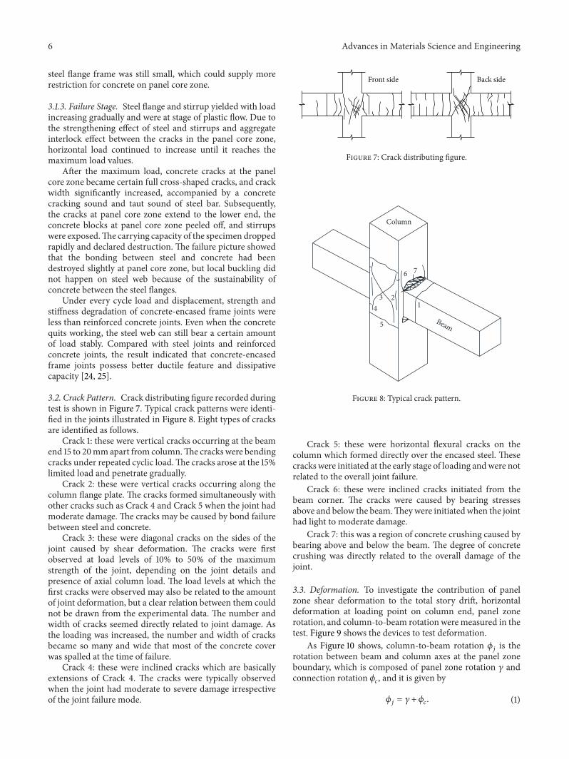
3.2. Crack Pattern. Crack distributing figure recorded duringtest is shown in Figure 7. Typical crack patterns were identi-fied in the joints illustrated in Figure 8. Eight types of cracksare identified as follows.
Crack 1: these were vertical cracks occurring at the beamend 15 to 20mmapart from column.The cracks were bendingcracks under repeated cyclic load.The cracks arose at the 15%limited load and penetrate gradually.
Crack 2: these were vertical cracks occurring along thecolumn flange plate. The cracks formed simultaneously withother cracks such as Crack 4 and Crack 5 when the joint hadmoderate damage. The cracks may be caused by bond failurebetween steel and concrete.
Crack 3: these were diagonal cracks on the sides of thejoint caused by shear deformation. The cracks were firstobserved at load levels of 10% to 50% of the maximumstrength of the joint, depending on the joint details andpresence of axial column load. The load levels at which thefirst cracks were observed may also be related to the amountof joint deformation, but a clear relation between them couldnot be drawn from the experimental data. The number andwidth of cracks seemed directly related to joint damage. Asthe loading was increased, the number and width of cracksbecame so many and wide that most of the concrete coverwas spalled at the time of failure.
Crack 4: these were inclined cracks which are basicallyextensions of Crack 4. The cracks were typically observedwhen the joint had moderate to severe damage irrespectiveof the joint failure mode.
Front side Back side
Figure 7: Crack distributing figure.
7
Column
Beam
123
4
5
6
Figure 8: Typical crack pattern.
Crack 5: these were horizontal flexural cracks on thecolumn which formed directly over the encased steel. Thesecracks were initiated at the early stage of loading andwere notrelated to the overall joint failure.
Crack 6: these were inclined cracks initiated from thebeam corner. The cracks were caused by bearing stressesabove and below the beam.Theywere initiatedwhen the jointhad light to moderate damage.
Crack 7: this was a region of concrete crushing caused bybearing above and below the beam. The degree of concretecrushing was directly related to the overall damage of thejoint.
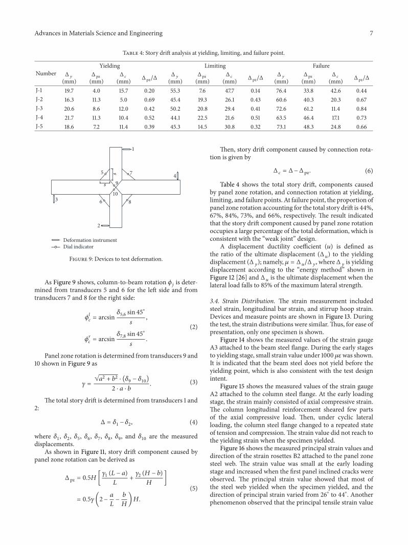
3.3. Deformation. To investigate the contribution of panelzone shear deformation to the total story drift, horizontaldeformation at loading point on column end, panel zonerotation, and column-to-beam rotation weremeasured in thetest. Figure 9 shows the devices to test deformation.
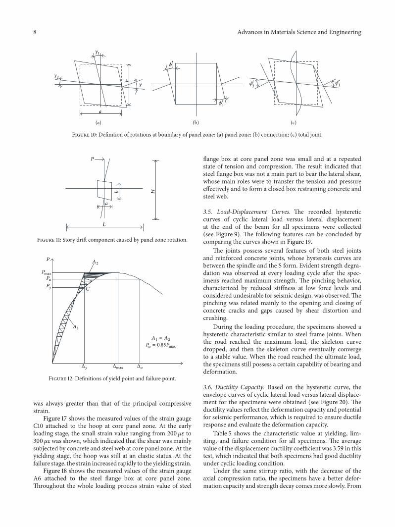
As Figure 10 shows, column-to-beam rotation 𝜙𝑗is the
rotation between beam and column axes at the panel zoneboundary, which is composed of panel zone rotation 𝛾 andconnection rotation 𝜙
𝑐, and it is given by
𝜙𝑗= 𝛾+𝜙
𝑐. (1)
Advances in Materials Science and Engineering 7
Table 4: Story drift analysis at yielding, limiting, and failure point.
NumberYielding Limiting Failure
Δ𝑦
(mm)Δ pz(mm)
Δ𝑐
(mm) Δ pz/ΔΔ𝑦
(mm)Δ pz(mm)
Δ𝑐
(mm) Δ pz/ΔΔ𝑦
(mm)Δ pz(mm)
Δ𝑐
(mm) Δ pz/Δ
J-1 19.7 4.0 15.7 0.20 55.3 7.6 47.7 0.14 76.4 33.8 42.6 0.44J-2 16.3 11.3 5.0 0.69 45.4 19.3 26.1 0.43 60.6 40.3 20.3 0.67J-3 20.6 8.6 12.0 0.42 50.2 20.8 29.4 0.41 72.6 61.2 11.4 0.84J-4 21.7 11.3 10.4 0.52 44.1 22.5 21.6 0.51 63.5 46.4 17.1 0.73J-5 18.6 7.2 11.4 0.39 45.3 14.5 30.8 0.32 73.1 48.3 24.8 0.66
Dial indicatorDeformation instrument
1
2
3
45 7
6 8
9
10
s
s
Figure 9: Devices to test deformation.
As Figure 9 shows, column-to-beam rotation 𝜙𝑗is deter-
mined from transducers 5 and 6 for the left side and fromtransducers 7 and 8 for the right side:
𝜙𝑙
𝑐= arcsin
𝛿5,6 sin 45∘
𝑠
,
𝜙𝑟
𝑐= arcsin
𝛿7,8 sin 45∘
𝑠
.
(2)
Panel zone rotation is determined from transducers 9 and10 shown in Figure 9 as
𝛾 =
√𝑎2+ 𝑏
2⋅ (𝛿9 − 𝛿10)
2 ⋅ 𝑎 ⋅ 𝑏. (3)
The total story drift is determined from transducers 1 and2:
Δ = 𝛿1 − 𝛿2, (4)
where 𝛿1, 𝛿2, 𝛿5, 𝛿6, 𝛿7, 𝛿8, 𝛿9, and 𝛿10 are the measureddisplacements.
As shown in Figure 11, story drift component caused bypanel zone rotation can be derived as
Δ pz = 0.5𝐻[𝛾1 (𝐿 − 𝑎)
𝐿
+
𝛾2 (𝐻 − 𝑏)
𝐻
]
= 0.5𝛾(2− 𝑎𝐿
−
𝑏
𝐻
)𝐻.
(5)
Then, story drift component caused by connection rota-tion is given by
Δ𝑐= Δ−Δ pz. (6)
Table 4 shows the total story drift, components causedby panel zone rotation, and connection rotation at yielding,limiting, and failure points. At failure point, the proportion ofpanel zone rotation accounting for the total story drift is 44%,67%, 84%, 73%, and 66%, respectively. The result indicatedthat the story drift component caused by panel zone rotationoccupies a large percentage of the total deformation, which isconsistent with the “weak joint” design.
A displacement ductility coefficient (𝑢) is defined asthe ratio of the ultimate displacement (Δ
𝑢) to the yielding
displacement (Δ𝑦); namely, 𝜇 = Δ
𝑢/Δ𝑦, whereΔ
𝑦is yielding
displacement according to the “energy method” shown inFigure 12 [26] and Δ
𝑢is the ultimate displacement when the
lateral load falls to 85% of the maximum lateral strength.
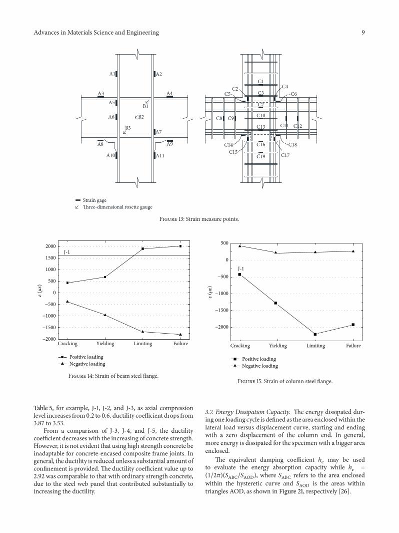
3.4. Strain Distribution. The strain measurement includedsteel strain, longitudinal bar strain, and stirrup hoop strain.Devices and measure points are shown in Figure 13. Duringthe test, the strain distributions were similar.Thus, for ease ofpresentation, only one specimen is shown.
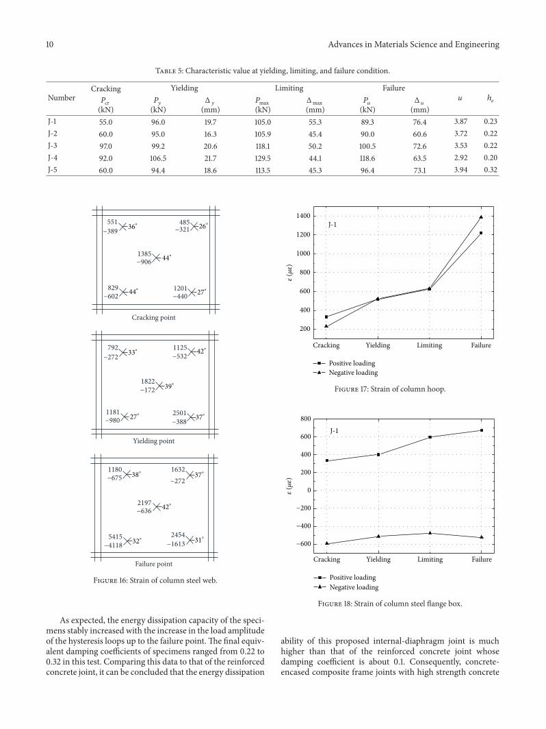
Figure 14 shows the measured values of the strain gaugeA3 attached to the beam steel flange. During the early stagesto yielding stage, small strain value under 1000 𝜇𝜀was shown.It is indicated that the beam steel does not yield before theyielding point, which is also consistent with the test designintent.
Figure 15 shows the measured values of the strain gaugeA2 attached to the column steel flange. At the early loadingstage, the strain mainly consisted of axial compressive strain.The column longitudinal reinforcement sheared few partsof the axial compressive load. Then, under cyclic lateralloading, the column steel flange changed to a repeated stateof tension and compression.The strain value did not reach tothe yielding strain when the specimen yielded.
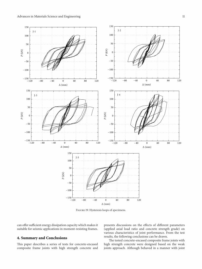
Figure 16 shows the measured principal strain values anddirection of the strain rosettes B2 attached to the panel zonesteel web. The strain value was small at the early loadingstage and increased when the first panel inclined cracks wereobserved. The principal strain value showed that most ofthe steel web yielded when the specimen yielded, and thedirection of principal strain varied from 26∘ to 44∘. Anotherphenomenon observed that the principal tensile strain value
8 Advances in Materials Science and Engineering
a
b
𝛾
𝛾1
𝛾2
(a)
𝜙lc
𝜙rc
(b)
𝜙lj 𝜙rj
(c)
Figure 10: Definition of rotations at boundary of panel zone: (a) panel zone; (b) connection; (c) total joint.
PHb
a
L
Figure 11: Story drift component caused by panel zone rotation.
P
PmaxPuPy
A2
C
A1
A1 = A2
Pu = 0.85Pmax
ΔuΔy Δmax
Figure 12: Definitions of yield point and failure point.
was always greater than that of the principal compressivestrain.
Figure 17 shows the measured values of the strain gaugeC10 attached to the hoop at core panel zone. At the earlyloading stage, the small strain value ranging from 200𝜇𝜀 to300 𝜇𝜀was shown, which indicated that the shear was mainlysubjected by concrete and steel web at core panel zone. At theyielding stage, the hoop was still at an elastic status. At thefailure stage, the strain increased rapidly to the yielding strain.
Figure 18 shows the measured values of the strain gaugeA6 attached to the steel flange box at core panel zone.Throughout the whole loading process strain value of steel
flange box at core panel zone was small and at a repeatedstate of tension and compression. The result indicated thatsteel flange box was not a main part to bear the lateral shear,whose main roles were to transfer the tension and pressureeffectively and to form a closed box restraining concrete andsteel web.
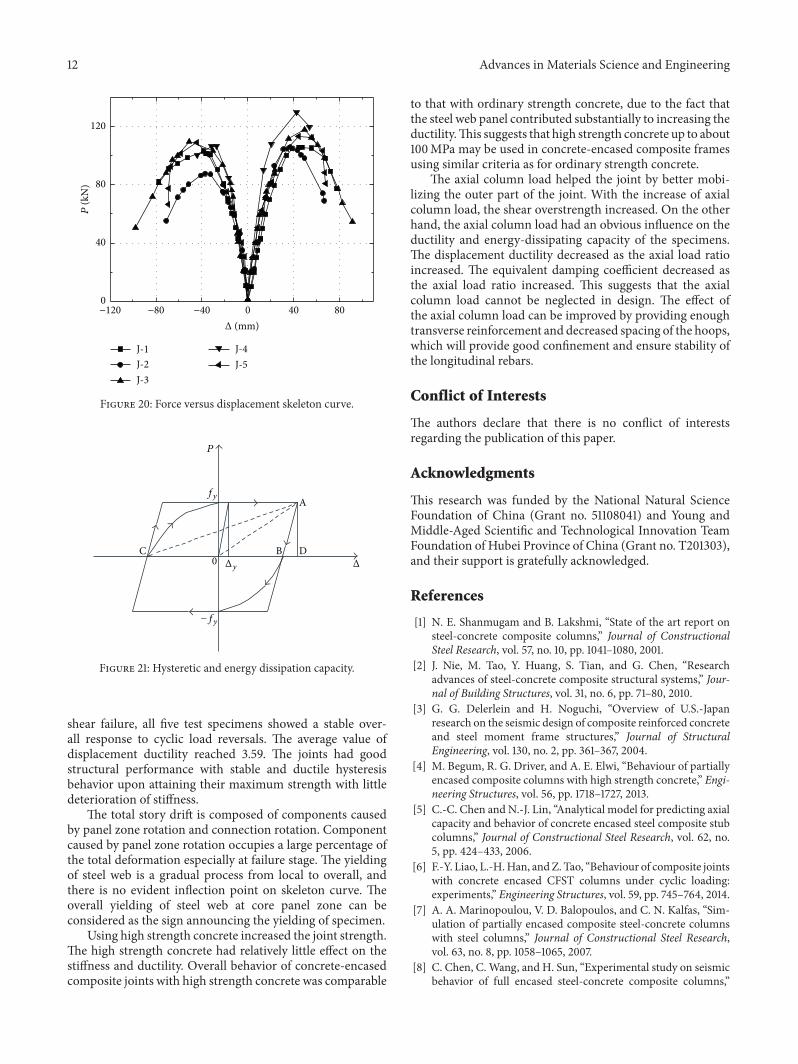
3.5. Load-Displacement Curves. The recorded hystereticcurves of cyclic lateral load versus lateral displacementat the end of the beam for all specimens were collected(see Figure 9). The following features can be concluded bycomparing the curves shown in Figure 19.
The joints possess several features of both steel jointsand reinforced concrete joints, whose hysteresis curves arebetween the spindle and the S form. Evident strength degra-dation was observed at every loading cycle after the spec-imens reached maximum strength. The pinching behavior,characterized by reduced stiffness at low force levels andconsidered undesirable for seismic design, was observed.Thepinching was related mainly to the opening and closing ofconcrete cracks and gaps caused by shear distortion andcrushing.
During the loading procedure, the specimens showed ahysteretic characteristic similar to steel frame joints. Whenthe road reached the maximum load, the skeleton curvedropped, and then the skeleton curve eventually convergeto a stable value. When the road reached the ultimate load,the specimens still possess a certain capability of bearing anddeformation.
3.6. Ductility Capacity. Based on the hysteretic curve, theenvelope curves of cyclic lateral load versus lateral displace-ment for the specimens were obtained (see Figure 20). Theductility values reflect the deformation capacity and potentialfor seismic performance, which is required to ensure ductileresponse and evaluate the deformation capacity.
Table 5 shows the characteristic value at yielding, lim-iting, and failure condition for all specimens. The averagevalue of the displacement ductility coefficient was 3.59 in thistest, which indicated that both specimens had good ductilityunder cyclic loading condition.
Under the same stirrup ratio, with the decrease of theaxial compression ratio, the specimens have a better defor-mation capacity and strength decay comesmore slowly. From
Advances in Materials Science and Engineering 9
Strain gageThree-dimensional rosette gauge
B1
B2
B3
A1 A2
A4A3
A9A8
A10 A11
A6
A5
A7
C1
C3C5C2 C4
C8 C9 C10
C11 C12
C14C15
C16
C13
C19
C18
C17
C6
C7
Figure 13: Strain measure points.
−2000
−1500
−1000
−500
0
500
1000
1500
2000
FailureLimitingYieldingCracking
Positive loadingNegative loading
J-1
𝜀(𝜇𝜀)
Figure 14: Strain of beam steel flange.
Table 5, for example, J-1, J-2, and J-3, as axial compressionlevel increases from 0.2 to 0.6, ductility coefficient drops from3.87 to 3.53.
From a comparison of J-3, J-4, and J-5, the ductilitycoefficient decreases with the increasing of concrete strength.However, it is not evident that using high strength concrete beinadaptable for concrete-encased composite frame joints. Ingeneral, the ductility is reducedunless a substantial amount ofconfinement is provided. The ductility coefficient value up to2.92 was comparable to that with ordinary strength concrete,due to the steel web panel that contributed substantially toincreasing the ductility.
−2000
−1500
−1000
−500
0
500
FailureLimitingYieldingCracking
Positive loadingNegative loading
J-1
𝜀(𝜇𝜀)
Figure 15: Strain of column steel flange.
3.7. Energy Dissipation Capacity. The energy dissipated dur-ing one loading cycle is defined as the area enclosedwithin thelateral load versus displacement curve, starting and endingwith a zero displacement of the column end. In general,more energy is dissipated for the specimen with a bigger areaenclosed.
The equivalent damping coefficient ℎ𝑒may be used
to evaluate the energy absorption capacity while ℎ𝑒=
(1/2𝜋)(𝑆ABC/𝑆AOD), where 𝑆ABC refers to the area enclosedwithin the hysteretic curve and 𝑆AOD is the areas withintriangles AOD, as shown in Figure 21, respectively [26].
10 Advances in Materials Science and Engineering
Table 5: Characteristic value at yielding, limiting, and failure condition.
NumberCracking Yielding Limiting Failure
u ℎ𝑒𝑃cr
(kN)𝑃𝑦
(kN)Δ𝑦
(mm)𝑃max(kN)
Δmax(mm)
𝑃𝑢
(kN)Δ𝑢
(mm)J-1 55.0 96.0 19.7 105.0 55.3 89.3 76.4 3.87 0.23J-2 60.0 95.0 16.3 105.9 45.4 90.0 60.6 3.72 0.22J-3 97.0 99.2 20.6 118.1 50.2 100.5 72.6 3.53 0.22J-4 92.0 106.5 21.7 129.5 44.1 118.6 63.5 2.92 0.20J-5 60.0 94.4 18.6 113.5 45.3 96.4 73.1 3.94 0.32
Cracking point
1385−906
−602829
−389551
−2721632
−4401201
−272792
1822−172
−3882501
−9801181
485−321
1180−675
−6362197
−5321125
2454−1613
5415−4118
Yielding point
Failure point
36∘
44∘
44∘
26∘
27∘
33∘
27∘
42∘
37∘
39∘
38∘
32∘
42∘
37∘
31∘
Figure 16: Strain of column steel web.
As expected, the energy dissipation capacity of the speci-mens stably increased with the increase in the load amplitudeof the hysteresis loops up to the failure point.The final equiv-alent damping coefficients of specimens ranged from 0.22 to0.32 in this test. Comparing this data to that of the reinforcedconcrete joint, it can be concluded that the energy dissipation
200
400
600
800
1000
1200
1400
Positive loadingNegative loading
J-1
FailureLimitingYieldingCracking
𝜀(𝜇𝜀)
Figure 17: Strain of column hoop.
−600
−400
−200
0
200
400
600
800
Positive loadingNegative loading
J-1
FailureLimitingYieldingCracking
𝜀(𝜇𝜀)
Figure 18: Strain of column steel flange box.
ability of this proposed internal-diaphragm joint is muchhigher than that of the reinforced concrete joint whosedamping coefficient is about 0.1. Consequently, concrete-encased composite frame joints with high strength concrete
Advances in Materials Science and Engineering 11P
(kN
)
150
100
50
0
−50
−100
−150
Δ (mm)−120 −80 −40 0 40 80 120
J-1
P(k
N)
150
100
50
0
−50
−100
−150
Δ (mm)−120 −80 −40 0 40 80 120
J-2
P(k
N)
150
100
50
0
−50
−100
−150
Δ (mm)−120 −80 −40 0 40 80 120
J-3
P(k
N)
150
100
50
0
−50
−100
−150
Δ (mm)−120 −80 −40 0 40 80 120
J-4
P(k
N)
150
100
50
0
−50
−100
−150
Δ (mm)−120 −80 −40 0 40 80 120
J-5
Figure 19: Hysteresis loops of specimens.
can offer sufficient energy dissipation capacity whichmakes itsuitable for seismic applications in moment-resisting frames.
4. Summary and Conclusions
This paper describes a series of tests for concrete-encasedcomposite frame joints with high strength concrete and
presents discussions on the effects of different parameters(applied axial load ratio and concrete strength grade) onvarious characteristics of joint performance. From the testresults, the following conclusions can be drawn.
The tested concrete-encased composite frame joints withhigh strength concrete were designed based on the weakjoints approach. Although behaved in a manner with joint
12 Advances in Materials Science and Engineering
−120 −80 −40 0 40 800
40
80
120
J-1J-2J-3
J-4J-5
P(k
N)
Δ (mm)
Figure 20: Force versus displacement skeleton curve.
P
fyA
DC B0 Δy
−fy
Δ
Figure 21: Hysteretic and energy dissipation capacity.
shear failure, all five test specimens showed a stable over-all response to cyclic load reversals. The average value ofdisplacement ductility reached 3.59. The joints had goodstructural performance with stable and ductile hysteresisbehavior upon attaining their maximum strength with littledeterioration of stiffness.
The total story drift is composed of components causedby panel zone rotation and connection rotation. Componentcaused by panel zone rotation occupies a large percentage ofthe total deformation especially at failure stage. The yieldingof steel web is a gradual process from local to overall, andthere is no evident inflection point on skeleton curve. Theoverall yielding of steel web at core panel zone can beconsidered as the sign announcing the yielding of specimen.
Using high strength concrete increased the joint strength.The high strength concrete had relatively little effect on thestiffness and ductility. Overall behavior of concrete-encasedcomposite joints with high strength concrete was comparable
to that with ordinary strength concrete, due to the fact thatthe steel web panel contributed substantially to increasing theductility.This suggests that high strength concrete up to about100MPa may be used in concrete-encased composite framesusing similar criteria as for ordinary strength concrete.
The axial column load helped the joint by better mobi-lizing the outer part of the joint. With the increase of axialcolumn load, the shear overstrength increased. On the otherhand, the axial column load had an obvious influence on theductility and energy-dissipating capacity of the specimens.The displacement ductility decreased as the axial load ratioincreased. The equivalent damping coefficient decreased asthe axial load ratio increased. This suggests that the axialcolumn load cannot be neglected in design. The effect ofthe axial column load can be improved by providing enoughtransverse reinforcement and decreased spacing of the hoops,which will provide good confinement and ensure stability ofthe longitudinal rebars.
Conflict of Interests
The authors declare that there is no conflict of interestsregarding the publication of this paper.
Acknowledgments
This research was funded by the National Natural ScienceFoundation of China (Grant no. 51108041) and Young andMiddle-Aged Scientific and Technological Innovation TeamFoundation of Hubei Province of China (Grant no. T201303),and their support is gratefully acknowledged.
References
[1] N. E. Shanmugam and B. Lakshmi, “State of the art report onsteel-concrete composite columns,” Journal of ConstructionalSteel Research, vol. 57, no. 10, pp. 1041–1080, 2001.
[2] J. Nie, M. Tao, Y. Huang, S. Tian, and G. Chen, “Researchadvances of steel-concrete composite structural systems,” Jour-nal of Building Structures, vol. 31, no. 6, pp. 71–80, 2010.
[3] G. G. Delerlein and H. Noguchi, “Overview of U.S.-Japanresearch on the seismic design of composite reinforced concreteand steel moment frame structures,” Journal of StructuralEngineering, vol. 130, no. 2, pp. 361–367, 2004.
[4] M. Begum, R. G. Driver, and A. E. Elwi, “Behaviour of partiallyencased composite columns with high strength concrete,” Engi-neering Structures, vol. 56, pp. 1718–1727, 2013.
[5] C.-C. Chen and N.-J. Lin, “Analytical model for predicting axialcapacity and behavior of concrete encased steel composite stubcolumns,” Journal of Constructional Steel Research, vol. 62, no.5, pp. 424–433, 2006.
[6] F.-Y. Liao, L.-H.Han, andZ. Tao, “Behaviour of composite jointswith concrete encased CFST columns under cyclic loading:experiments,” Engineering Structures, vol. 59, pp. 745–764, 2014.
[7] A. A. Marinopoulou, V. D. Balopoulos, and C. N. Kalfas, “Sim-ulation of partially encased composite steel-concrete columnswith steel columns,” Journal of Constructional Steel Research,vol. 63, no. 8, pp. 1058–1065, 2007.
[8] C. Chen, C. Wang, and H. Sun, “Experimental study on seismicbehavior of full encased steel-concrete composite columns,”
Advances in Materials Science and Engineering 13
Journal of Structural Engineering, vol. 140, no. 6, Article ID04014024, 2014.
[9] Antonius and I. Imran, “Experimental study of confined low-, medium- and high-strength concrete subjected to concentriccompression,” ITB Journal of Engineering Science, vol. 44, no. 3,pp. 252–269, 2012.
[10] E. Ellobody, B. Young, and D. Lam, “Behaviour of normal andhigh strength concrete-filled compact steel tube circular stubcolumns,” Journal of Constructional Steel Research, vol. 62, no.7, pp. 706–715, 2006.
[11] J. R.DelViso, J. R. Carmona, andG. Ruiz, “Shape and size effectson the compressive strength of high-strength concrete,”Cementand Concrete Research, vol. 38, no. 3, pp. 386–395, 2008.
[12] A. R. Murthy, B. K. R. Prasad, and N. R. Iyer, “Estimation offracture properties for high strength and ultra high strengthconcrete beams and size effect,” International Journal of DamageMechanics, vol. 22, no. 8, pp. 1109–1126, 2013.
[13] Y. K. Ju, J.-Y. Kim, and S.-D. Kim, “Experimental evaluationof new concrete encased steel composite beam to steel columnjoint,” Journal of Structural Engineering, vol. 133, no. 4, pp. 519–529, 2007.
[14] J. Fan, Q. Li, J. Nie, and H. Zhou, “Experimental study onthe seismic performance of 3D joints between concrete-filledsquare steel tubular columns and composite beams,” Journal ofStructural Engineering, vol. 140, no. 12, Article ID 04014094,2014.
[15] R. Realfonzo, A. Napoli, and J. G. R. Pinilla, “Cyclic behaviorof RC beam-column joints strengthened with FRP systems,”Construction and Building Materials, vol. 54, pp. 282–297, 2014.
[16] V. C. L. Gonzalez and G. Moriconi, “The influence of recycledconcrete aggregates on the behavior of beam–column jointsunder cyclic loading,” Engineering Structures, vol. 60, pp. 148–154, 2014.
[17] M.-X. Tao, J.-S. Fan, and J.-G. Nie, “Seismic behavior of steelreinforced concrete column-steel truss beam hybrid joints,”Engineering Structures, vol. 56, pp. 1557–1569, 2013.
[18] ACI Committee, Building Code Requirements for StructuralConcrete (ACI 318-05) and Commentary (ACI 318R-05), Ameri-can Concrete Institute, 2005.
[19] American Institute of Steel Construction, Load and ResistanceFactor Design Specification for Structural Steel Buildings, AISC,Chicago, Ill, USA, 3rd edition, 1999.
[20] JGJ, “Technical specification for steel reinforced concrete com-posite structures,” JGJ 138-2001, Architecture Industrial Press ofChina, Beijing, China, 2001 (Chinese).
[21] Architectural Institute of Japan, Standard for the Calculationof Steel-Reinforced Concrete Structures (AIJ-SRC), ArchitecturalInstitute of Japan, Tokyo, Japan, 2010, (Japanese).
[22] JGJ, “Technical specification for application of high strengthconcrete,” JGJ/T 281-2012, Architecture Industrial Press ofChina, Beijing, China, 2012 (Chinese).
[23] China Standard Press, GB/T228.1-2010, Metallic Materials-Tensile Testing-Part 1: Method of Test at Room Temperature,China Standard Press, Beijing, China, 2011, (Chinese).
[24] Y. C. Wang, X. H. Dai, and C. G. Bailey, “An experimentalstudy of relative structural fire behaviour and robustness ofdifferent types of steel joint in restrained steel frames,” Journal ofConstructional Steel Research, vol. 67, no. 7, pp. 1149–1163, 2011.
[25] A. Filiatrault, S. Pineau, and J. Houde, “Seismic behavior ofsteel-fiber reinforced concrete interior beam-column joints,”ACI Materials Journal, vol. 92, no. 5, pp. 543–552, 1995.
[26] Architecture Industrial Press of China, JGJ101-96, Specificationfor Seismic Test Method, Architecture Industrial Press of China,Beijing, China, 1997, (Chinese).

Submit your manuscripts athttp://www.hindawi.com
ScientificaHindawi Publishing Corporationhttp://www.hindawi.com Volume 2014
CorrosionInternational Journal of
Hindawi Publishing Corporationhttp://www.hindawi.com Volume 2014
Polymer ScienceInternational Journal of
Hindawi Publishing Corporationhttp://www.hindawi.com Volume 2014
Hindawi Publishing Corporationhttp://www.hindawi.com Volume 2014
CeramicsJournal of
Hindawi Publishing Corporationhttp://www.hindawi.com Volume 2014
CompositesJournal of
NanoparticlesJournal of
Hindawi Publishing Corporationhttp://www.hindawi.com Volume 2014
Hindawi Publishing Corporationhttp://www.hindawi.com Volume 2014
International Journal of
Biomaterials
Hindawi Publishing Corporationhttp://www.hindawi.com Volume 2014
NanoscienceJournal of
TextilesHindawi Publishing Corporation http://www.hindawi.com Volume 2014
Journal of
NanotechnologyHindawi Publishing Corporationhttp://www.hindawi.com Volume 2014
Journal of
CrystallographyJournal of
Hindawi Publishing Corporationhttp://www.hindawi.com Volume 2014
The Scientific World JournalHindawi Publishing Corporation http://www.hindawi.com Volume 2014
Hindawi Publishing Corporationhttp://www.hindawi.com Volume 2014
CoatingsJournal of
Advances in
Materials Science and EngineeringHindawi Publishing Corporationhttp://www.hindawi.com Volume 2014
Smart Materials Research
Hindawi Publishing Corporationhttp://www.hindawi.com Volume 2014
Hindawi Publishing Corporationhttp://www.hindawi.com Volume 2014
MetallurgyJournal of
Hindawi Publishing Corporationhttp://www.hindawi.com Volume 2014
BioMed Research International
MaterialsJournal of
Hindawi Publishing Corporationhttp://www.hindawi.com Volume 2014
Nano
materials
Hindawi Publishing Corporationhttp://www.hindawi.com Volume 2014
Journal ofNanomaterials