Embed Size (px)
Citation preview
Research ArticleDesign of an Active Multispectral SWIR Camera System for SkinDetection and Face Verification
Holger Steiner1 Sebastian Sporrer1 Andreas Kolb2 and Norbert Jung1
1Safety and Security Research Institute (ISF) Bonn-Rhein-Sieg University of Applied Sciences Grantham-Allee 2053757 Sankt Augustin Germany2Computer Graphics and Multimedia Systems Group University of Siegen 57076 Siegen Germany
Correspondence should be addressed to Holger Steiner holgersteinerh-brsde
Received 23 December 2014 Accepted 5 March 2015
Academic Editor Yongqiang Zhao
Copyright copy 2016 Holger Steiner et al This is an open access article distributed under the Creative Commons Attribution Licensewhich permits unrestricted use distribution and reproduction in any medium provided the original work is properly cited
Biometric face recognition is becoming more frequently used in different application scenarios However spoofing attacks withfacial disguises are still a serious problem for state of the art face recognition algorithms This work proposes an approach to faceverification based on spectral signatures of material surfaces in the short wave infrared (SWIR) range They allow distinguishingauthentic human skin reliably from other materials independent of the skin typeWe present the design of an active SWIR imagingsystem that acquires four-band multispectral image stacks in real-time The system uses pulsed small band illumination whichallows for fast image acquisition and high spectral resolution and renders it widely independent of ambient light After extractingthe spectral signatures from the acquired images detected faces can be verified or rejected by classifying the material as ldquoskinrdquoor ldquono-skinrdquo The approach is extensively evaluated with respect to both acquisition and classification performance In additionwe present a database containing RGB and multispectral SWIR face images as well as spectrometer measurements of a variety ofsubjects which is used to evaluate our approach and will be made available to the research community by the time this work ispublished
1 Introduction
Face recognition is a very important aspect for biometricsystems and a very active research topic [1] The humanface has advantages over other biometric traits as it caneasily be captured in a nonintrusive way from a distance[2] Consequently biometric face recognition systems arebecoming more frequently used for example at airports inthe form of automated border control systems for accesscontrol systems at critical infrastructure or even for userlog-on and authentication in computers or modern smart-phones However despite the significant progress in thefield face recognition still faces serious problems in real-world scenarios when dealing with changing illuminationconditions poses and facial expressions as well as facialdisguises (ldquofakesrdquo) such as masks [3]
To overcome the problem of changing illumination con-ditions the use of infrared imagery has been proposed in therecent years Frontal illumination of faces with near infrared
light that is invisible to the human eye helps to reduce theinfluence of ambient light significantly without distracting orblinding the subjects [4]
For the detection of fakes also referred to as livenessdetection at least three forms of spoofing have to be consid-ered photographs prerecorded or live video (eg shown onamobile device) and partial or complete facial disguises suchas masks The impact of such attacks on face recognition hasbeen researched in several studies for example in the contextof the research project TABULA RASA [5] Although somecountermeasures for such attacks have been proposed [6ndash8]especially the attacks with facial disguises andmasks they arestill a problem for state of the art face recognition systems
Masks can bemanufactured using very differentmaterialswith varying textures and surface properties for examplepaper latex rubber plastics or silicon Due to the variationsfound in human skin color and texture distinguishing anypossible material from genuine human skin using only thevisual domain is a very difficult task [9]
Hindawi Publishing CorporationJournal of SensorsVolume 2016 Article ID 9682453 16 pageshttpdxdoiorg10115520169682453
2 Journal of Sensors
01020304050607080
Wavelength (nm)
Rem
issio
n (
)
Skin type 1Skin type 2Skin type 3Skin type 4Skin type 5
Skin type 6Plastic maskResin maskPaper maskPrint on cotton
400
500
600
700
800
900
1000
1100
1200
1300
1400
1500
1600
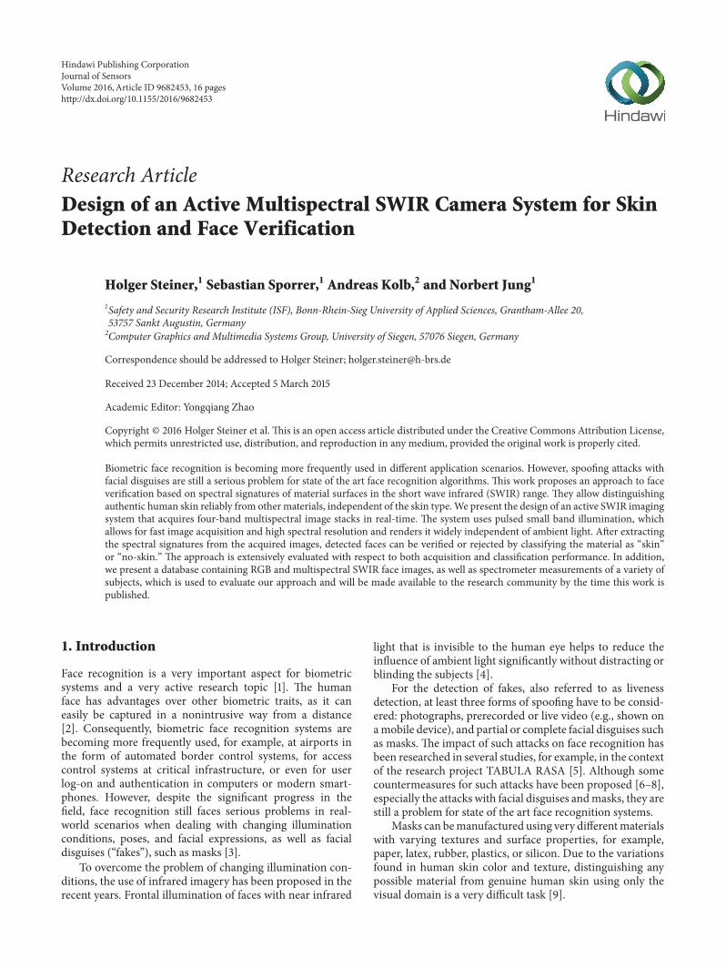
Figure 1 Spectral remission intensities of skin and different fakematerials
To overcome these problems the use of infrared imag-ing has been proposed in prior work Jacquez et al [10]have shown that human skin has very specific remissioncharacteristics in the infrared spectral range the spectralremission of skin above 1200 nm is widely independent of theskin type and mainly influenced by the absorption spectrumof water In addition the spectral remission of most othermaterials differs strongly from that of skin Figure 1 showsthe remission intensities of human skin in the visual andinfrared spectral range up to 1700 nm for six different skintypes denoted as skin types 1 (very light colored) to 6(very dark colored) after Fitzpatrick [11] compared to theremission spectra of materials that might be used to createfacial disguises
In the literature the infrared spectrum below 1400 nmis commonly referred to as the near infrared (NIR) bandand the spectrum between 1400 nm and 3000 nm as theshort wave infrared (SWIR) band This work focuses on thespectral range of 900 nmup to 1700 nmWhendescribing thiswavelength range most researchers use only the term SWIRin order to distinguish it from work limited to the NIR rangebelow 1000 nm This paper will adopt this simplification andalso use only the term SWIR in the following to describe thiswavelength range The existing approaches that make use ofthe SWIR spectral range can be classified into four groupsmultispectral image acquisition using multiple cameras withband pass filters [9 12] hyperspectral imagers [13] singlecameras using filter-wheels with band pass filters for sequen-tial multispectral image acquisition [14] and more recentlysingle cameras with Bayer-like band pass filter patternsapplied directly on the sensor [15] All of these systems arepassive (filter-based) and require sufficient illumination bydaylight or external lighting They will be discussed in detailin Section 2
In our previous work we presented an active multispec-tral point sensor for contactless skin detection which can beused for both safety and security applications as well as aldquoproof of conceptrdquo of an active multispectral imaging system
[16 17] Both the sensor and the imaging system acquire aldquospectral signaturerdquo of object surfaces a specific combinationof remission intensities in distinct narrow wavebands that isused for the classification of the objectrsquos surface material
The contributions of this work are twofold
(1) Based on our prior work we present an improved sys-tem design of an active multispectral camera systemoptimized for face verification The system acquiresfour-band multispectral image stacks in the SWIRrange in real-time The main improvements are
(i) optimized illumination homogeneity(ii) extensive camera system calibration(iii) compensation of motion artifacts(iv) advanced classification methods(v) an elaborate evaluation regarding both skin
detection and face verification
(2) We present data from a study with more than 130participants (at the time of writing) that combinesspectral measurements at several points on faces andlimbs with pictures taken with both an RGB cameraand the presented multispectral camera system Asubset of this database reduced by the images ofparticipants that did not agree to publication willbe made available to the research community on ourwebsite (httpisfh-brsde) by the time this work ispublished We expect the published database to con-tain spectrometer data from at least 120 participantsand image data from at least 50 participants
The remainder of this paper is organized as followsSection 2 gives an overview of the related work Section 3presents the design of the proposed camera system with afocus on hardware Sections 4 and 5 describe the methodsapplied for image preprocessing and analysis In Section 6the camera system and the proposed skin and fake detectionmethod are evaluated For this purpose a database of spec-trometer measurements as well as multispectral SWIR andRGB images is presented Section 7 concludes the paper
2 Related Work
In the following we will focus on work that is directly relatedto our approach that is based on the SWIR spectral range Amore general comprehensive overview of methods for facerecognition in the infrared spectrum including the thermalinfrared range can be found in [3]
Taking advantage of the specific remission character-istics of human skin in the SWIR spectral range for itsdetection is not a new idea but this approach has (to thebest of our knowledge) only rarely been researched in theliterature
In 2000 Pavlidis and Symosek [9] demonstrated thatthe SWIR range has many advantages for face detection ingeneral and for disguise detection in specific They proposeda dual band camera system consisting of two coregisteredcameras with one camera having a spectral sensitivity below
Journal of Sensors 3
SWIR camera
Distortion correction
Normalization
Imageprocessing
Imageanalysis
Nonlinearity correction
Face verification
Multispectral image
Multispectral image
Skindetection
Facedetection
Motion compensation
Hardwarecamera system
Computer
Embeddedcontrol
Ring light
system
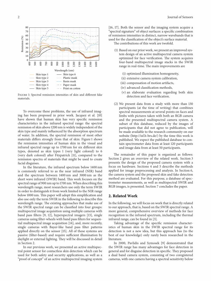
Figure 2 Building blocks of the proposed approach
1400 nm (ideally 800 nm to 1400 nm) and the second camerahaving a spectral sensitivity above 1400 nm (ideally 1400 nmup to 2200 nm) Their system can work with either sunlightor artificial illumination and it uses a fusion algorithm basedon weighted differences to detect skin in the acquired imagesDepending on the spectral distribution of the illuminationsource theweighting factors have to be adapted as the systemis not independent of ambient light The authors concludethat their system achieves very good face and disguise detec-tion capabilities compared to systems in the visual spectrumonly limited when it comes to the detection of surgical facealterations where they see an advantage of systems usingthe thermal infrared range In a later publication [18] theypresented an extension of the system with a third camerafor the visual spectrum and a more advanced face detectionapproach that includedmultiband eye and eyebrowdetectionTheir system uses beam splitters to allow all cameras to viewthe scene from the same vantage point in order to avoidproblems with image registration
At the US Air Force Institute of Technology Nunezand Mendenhall [12 13] researched the use of hyperspectralSWIR imagery to detect skin for remote sensing applicationsThe authors acquired images in 81 narrow spectral bandsbetween 900 nm and 1744 nm with a hyperspectral cameraand introduced a detailed reflectance model of human skinbased on this data For real-time and in the field use theauthors propose a multicamera system to acquire images indistinct narrow wavebands using different band pass filterson each camera To avoid problems with image registrationthis system uses dichroic mirrors to split up the beam so thatall cameras share one single lens and view the scene from thesame vantage point
More recently Bourlai et al [14] presented amultispectralSWIR image acquisition system using a single camera withan attached rotating filter wheel The filter wheel is equippedwith five band pass filters with a full width at half maximum(FWHM) of 100 nm around the peak wavelengths 1150 nm1250 nm 1350 nm 1450 nm and 1550 nm By synchronizingthe camerarsquos integration time to the filter wheel the systemcan capture all five waveband images within 260ms (ie at arate of asymp38 frames per second (FPS))
Bertozzi et al [15] propose a camera with a broadbandsensor for both the visual and SWIR spectral range (ie400 nm to 1700 nm) that is equippedwith a Bayer-likemosaicfilter pattern directly on top of the pixel array One clearfilter (full bandwidth) is combined with three high pass filterswith cut-off wavelengths of 540 nm 1000 nm and 1350 nmBy subtracting the acquired values of neighboring pixels withdifferent filters multispectral images in the four wavebandsof approximately 400ndash600 nm 600ndash1000 nm 1000ndash1300 nmand 1300ndash1700 nm can be calculated
Due to the passive (filter-based) system design thespectral distribution of the ambient illumination has a stronginfluence on the multispectral images acquired by any ofthese systems In contrast to this the approach proposedin this work uses active small band illumination insteadof filters and is widely independent of ambient light Itcombines a comparably high acquisition speed with highspectral resolution and robust detection
3 Camera System Design
The approach described in this work is composed of threemajor building blocks illustrated in Figure 2 which weexplain in sequential order This section describes the designgoals and decisions for the camera system with a focus on thehardware Section 4 presents the low-level image processingmethods while Section 5 will focus on higher level imageprocessing and analysis
31 DesignGoals In general face detection approaches in thecontext of biometric applications have strong requirementswith respect to robustness and speed of the detection Hererobustness includes both accurate detection under varyingexternal conditions such as lighting and a reliable exclusionof spoofing attacks
Even though we do not tackle any specific applicationscenario we formulate the following rather generic designgoals that allow the realization of various applications
(i) The imaging system should be independent of ambi-ent lightThe spectral distribution or any flickering of
4 Journal of Sensors
LED ring light935 1060 1300 1550
nmnmnmnm
SWIRcamera
Trigger IN GigE
Microcontrollersystem
LEDdriver USB Camera
trigger
PC
Image data
Acquisition control
Figure 3 Schematic of the camera system setup
the light sourcemust not distort the extracted spectralsignatures
(ii) The acquisition time of a complete multispectralimage stack should be as short as possible
(iii) Moving objects must not lead to false classifications(iv) Face and disguise detection must work independent
of a subjectrsquos skin type age or gender(v) The operation range should be oriented at typi-
cal cooperative user scenarios with short ranges ofseveral meters (as opposed to long range imagingscenarios with distances of more than 100 meters[19])
(vi) The system should require only one single cameraThis avoids the need to align the optical path of mul-tiple cameras or to apply complex image registrationmethods and reduces the costs of the imaging systemas SWIR cameras are still very expensive
None of the existing approaches described in Section 2can reach all of these goals
32 System Setup Based on the specified design goals wepropose a system setup consisting of a single SWIR camerasensitive to a spectral range of 900ndash1700 nmwith an attachedLED ring light that illuminates the face of a subject infour distinct narrow wavebands within this spectral range(one at a time) as illustrated in Figure 3 A microcontrollersystem which is embedded into the ring light moduletriggers short pulses in alternating distinct wavebands andsignals the camera to start and stop the exposure of a newimage synchronized to the light pulse The camera transmitsthe acquired images to a connected computer via GigabitEthernet which in turn is connected to the microcontrollersystem viaUSB in order to configure and start the acquisitionWe also developed a special software tool that allows a user tocontrol the image acquisition and to perform all related imageprocessing and analysis tasks with a graphical user interface
33 Design of the LED Ring Light Using LEDs to implementthe illuminationmodule is an obvious choice as they produce
Table 1 Number (119899) peak wavelength (120582119901) FWHM (Δ12058205)radiated power (Φ119890) and total radiated power (sumΦ119890) of the LEDtypes used on the ring light
119899 120582119901 [nm] Δ12058205 [nm] Φ119890 [mW] sumΦ119890 [mW]10 935 65 30 30030 1060 50 55 16520 1300 70 85 17030 1550 130 50 150
rather narrow band illumination and can be pulsed withhigh intensities and variable frequencies Based on findingsin our previous work [16] we selected four wavebands forour current setup that are well suited for skin detection anddesigned an LED ring light with 90 LEDs The number ofLEDs for each waveband is shown in Table 1 and was chosenwith regard to both the expected radiated power of each LEDand a uniform distribution of the LEDs on the ring light
A uniform distribution of the LEDs around the cameralens as well as similar viewing angles and radiant pat-terns of the different LED types is very important inorder to achieve a homogeneous illumination Otherwisethe extracted spectral signatures of an object would differdepending on the objectrsquos position in relation to the ringlight To avoid this problem we selected LEDs of thesame model and manufacturer (Roithner-Laser ELD-935-525 ELD-1060-525 ELD-1300-535 and ELD-1550-525) andperformed optical simulations to find the optimal distribu-tion of the different numbers of LEDs per waveband Forthis purpose we modeled the single LEDs as light sourcesusing the FRED Optical Engineering (Photon EngineeringLLC httpphotonengrcom) software by specifying theirtypical peak wavelengths spectral and radiant power distri-butions as defined by their datasheets FRED performs raytracing to simulate the propagation of light from each lightsource to a virtual target plane It also provides a scriptinglanguage and batch processing capabilities to run a series ofsimulationswith different parametersThiswaywe compareddifferent placement patterns and varying positions for theLEDs by simulating the resulting intensity distribution for
Journal of Sensors 5
935nm
1060nm
1300nm
1550nm
(a)
2000
2000
1500
1000
1000
500
0
0
minus500
minus1000
minus1000
minus1500
minus2000
minus2000Lo
caly
-axi
s (m
m)
Local x-axis (mm)
(b)
Figure 4 Distribution of the different LED types on the ring light (a) and resulting illumination distribution and homogeneity (b) projectedon a virtual analysis plane in 5m distance
each waveband on the target plane Ideally the normalizedintensity distributions of all wavebands should be identicalleading to a homogeneous ldquocolorrdquo on the target The bestsolutionwe found and the illumination distribution it createdare shown in Figure 4 Due to the visualization of the fourSWIRwavebands in yellow red green and blue the resulting(mixed) color is a soft yellow Inhomogeneities would benoticeable by local changes in the color tone but cannot beobserved
34 Eye Safety Evaluation Eye safety is a critical aspectof high power SWIR illumination sources as radiationwith a wavelength of up to 1400 nm can still penetratethe human eye and cause thermal damage to the retinaThe directive 200625EG of the European Union definesbinding permissible limits for illumination systems withpulsed light sources which should be measured as specifiedby the applicable standards For our camera system this isDIN EN 62471 The directive defines limits for the effectiveradiance 119871119877 on the retina which is weighted by a factordepending on the wavelength of the radiation and the totalirradiance 119864IR on the cornea in a measurement distance of119889 = 02m
As the necessary measurement setup was not available tous we analyzed the incident power of the SWIR radiationon the eye of an observer standing in the ldquosweet spotrdquo ofthe ring light based on the optical simulation Assuming apupil diameter of 7mm the maximum incident power at adistance of 119889 = 02m is achieved by the 935 nm wavebandand reaches a level of 119875eye = 069mW This corresponds to atotal irradiance of 119864IR asymp 173Wm2
Table 2 Effective radiance and total irradiance of the ring lightrsquosmost critical waveband (935 nm) on the eye of an observer in adistance of 119889 = 02m for short and very long observation times
119871119877 [W(m2sdotsr)] 119864IR [Wm2]
Simulation mdash 173Worst case scen 1355 25Limit 119905 gt 1000 s asymp545000 100Limit 119905 le 10 s ge25 sdot 106 ge3200
Using a model of our ring light that is simplified inthe ldquosafe directionrdquo we cross-checked this result using thespecifications given in the LEDs datasheetThe typical radiantintensity of one 935 nmLED is given as 119868119890 = 01Wsr Nowweassume (at worst case) that all LEDs for the 935 nmwavebandare continuously powered and directly adjacent so that thecombined radiant intensity of 119899 LEDs can be approximatedas 119868 asymp 119868119890 sdot 119899 and the radiating surface as 119860 asymp 119899 sdot 119860LED Nowwe can calculate 119871119877 and 119864IR as follows
119871119877 =
119868
119860
sdot 119877 (120582)
119864IR =
119868
1198892
(1)
with 119877(120582) being a correction factor according to directive200625EG and 119889 = 02m being the distance of an observeraccording to DIN EN 62471
Table 2 shows both our results and the limits defined bythe EU directive As expected the total irradiance calculatedusing the simplified ldquoworst caserdquo model is a little higher than
6 Journal of Sensors
Exposure trigger
935nm LEDs1060nm LEDs1300nm LEDs1550nm LEDs
0 10 20 30 40 50
(ms)
Figure 5 Timing diagram of the signals given by the microcontroller system
the results from simulation showing its plausibility Still thecalculated values are by far below the permissible limits evenif the observer stares right into the ring light for a very longtime This leaves some headroom for further increases of thering lightrsquos output power
35 Image Acquisition Principle In practice the ring light isworking as a pulsed light source The microcontroller systemenables its different wavebands one after the other in a fixedorder and simultaneously triggers the camera exposure Toremove the influence of ambient light in each acquisitioncycle an additional camera exposure is triggered without thering light flashing This reference image is subtracted fromeach of the other images in preprocessing so that only lightemitted by the ring light in one single waveband remains onthese images which we call waveband images Each set ofwaveband images and its corresponding reference image arecombined in a multispectral image stack This method workswell for ambient light from continuous light sources suchas daylight Here all light sources with intensity variationsthat are either very slow or very fast compared to one fullacquisition cycle can be regarded as continuous Howeverldquoflickeringrdquo or pulsed light sources changing their intensitywith frequencies in a magnitude similar to the acquisitionfrequency might cause distortions of the spectral signaturesIn practice most flickering light sources are incandescentor fluorescent lamps flickering at twice the local powerline frequency of 50Hz or 60Hz therefore having periodsof 10ms or 83ms respectively By using exposure timesmatching this period or any multiples of it their influencecan easily be reduced to a negligible level
Our current setup is based on an Allied Vision GoldeyeG-032 SWIR camera which is equipped with an indiumgallium arsenide (InGaAs) sensor and features a maximumframe rate of 100 frames per second (FPS) at its full resolutionof 636 sdot 508 pixels with 14-bit AD conversion Due tothe camerarsquos very short readout time it can be operatedat this frame rate with an exposure time close enough to10ms to remove the effect of flickering lamps Figure 5illustrates the chronological order of the signals given by themicrocontroller system within one full acquisition cycle of50ms resulting in an effective frame rate of 20 FPS
4 Image Preprocessing
Each image acquired by the SWIR camera is transmitted to aPC via Gigabit Ethernet Simultaneously the microcontroller
system tells the PC which waveband of the ring light hasbeen active during the exposure via USB connection Giventhis information the software running on the PC performsseveral preprocessing steps to optimize andmatch the imagesin order to compose a multispectral image stack
41 Fixed Pattern Noise Correction Despite the camerarsquosinternal two-point nonlinearity correction (NUC) underex-posed images show significant fixed pattern noise depend-ing on the actual pixel intensity As the system designrequires taking one reference image without flashing thering light this noise will have an influence on images takenin dark environments To analyze the sensorrsquos behavior indetail the sensor area was homogeneously illuminated usingan adjustable quartz halogen lamp through an integrating(Ulbricht) sphere and 70 images with increasing brightnesswere takenThis image data is used as a look up table to applya multiple-point nonlinearity correction to every single pixelFigure 9 demonstrates the effectiveness of this method
42 Motion Compensation In the next step the wavebandimages of one acquisition cycle are combined with a mul-tispectral image stack As the waveband images have beenacquired sequentially the positions of any moving object orperson in the scene might have changed between each imageof the stack In practice this will lead to motion artifacts andpotentially cause false classifications due to distorted spectralsignatures This problem is common to all approaches thatneed to coregister sequentially acquired images such as filterwheel camera systems [14]
To solve this problem we propose a frame interpolationmethod based on motion estimation and compensationtechniques to properly align all edges in every image of thestack For this purpose optical flow methods have proven tobe a very effective but computationally expensive approach[20] sufficiently high performance for real-time applicationscan currently only be achieved by implementations usinggraphics hardware (GPUs) Hoegg et al [21] demonstratedthat this approach can also be used to compensate motionin coregistered sequential images acquired by a time of flightcamera
However optical flow cannot be applied on our datadirectly as illumination conditions and intensity values ofobject surfaces might differ strongly between the wavebandimages In particular the first step in image merging thesubtraction of the (not actively illuminated) reference imagemight cause problems properly exposed image areas with
Journal of Sensors 7
ti0 ti1 ti2 ti3 ti4
t
Ii0 Ii1 Ii2 Ii3 Ii4
Mi Mi+1
ΔtT = 5 middot Δt
ti+10 ti+11 ti+12 ti+13 ti+14
Ii+10 Ii+11 Ii+12 Ii+13 Ii+14
Figure 6 Image sequence of two successive multispectral image stacks 119872119894 and 119872119894+1 with 119899 = 5 images
Ii0 (reference image) Ii1 (waveband 1) Optical flow Ii0rarrIi1
(a)
Ii1 (waveband 1) Ii+11 (waveband 1) Optical flow Ii1rarrIi+11
(b)
Figure 7 Optical flow between waveband image 1198681198941 and its reference image 1198681198940 (a) and between 1198681198941 and its successor 119868119894+11 (b) Colored pixelsrepresent detected motion
much detail in the actively illuminated waveband imagesmight be completely dark and without detail in the referenceimage
Therefore we use the following approach to motioncompensation consider a full multispectral image stack 119872119894with 119894 isin N being a sequential number consisting of 119899 images119868119894119908 acquired at times 119905119894119908 119908 = 0 119899 minus 1 Furthermorewe assume a discrete and equidistant acquisition time Δ119905 =
119905119894119908+1 minus119905119894119908 for each image 119868119894119908 and a constant acquisition time119879 = 119905119894+10 minus 1199051198940 = 119899Δ119905 for the full image stack as illustrated inFigure 6
As we cannot successfully apply optical flow directly tothe sequence of images that is between 119868119894119908 and 119868119894119908+1 asshown in the upper row of Figure 7 we also consider asubsequent multispectral image stack 119872119894+1 and apply optical
flow for corresponding images that is between 119868119894119908 and119868119894+1119908 119908 = 1 119899 minus 1 in a bidirectional manner resultingin a set of displacement maps (vector fields) Consider
Forward flow 119865(119894119908)rarr (119894+1119908) 119908 = 1 119899 minus 1
Backward flow 119865(119894+1119908)rarr (119894119908) 119908 = 1 119899 minus 1
(2)
As 119868119894119908 and 119868119894+1119908 have both been acquired with the sameillumination conditions the results of this operation aremuch better as shown in the lower row of Figure 7 Assum-ing a constant and linear motion between correspondingimages 119868119894119908 and 119868119894+1119908 every vector 119865(119894119908)rarr (119894+1119908)(119909 119910) in thedisplacement maps describing the movement of pixel (119909 119910)
between 119868119894119908 and 119868119894+1119908 can be regarded as a linear combi-nation of 119899 identical partial vectors (1119899)119865(119894119908)rarr (119894+1119908)(119909 119910)
8 Journal of Sensors
describing a pixels movement between 119868119894119908 and 119868119894119908+1 Basedon this assumption we now apply the forward and backwarddisplacement maps partially to estimate the images
119868119894+1119908 atintermediate times 119905119894+10 resulting in
119868119894+1119908 =
(119899 minus 119908)
119899
119865(119894119908)rarr (119894+1119908) [119868119894119908] +
119908
119899
119865(119894+1119908)rarr (119894119908) [119868119894+1119908] (3)
where 119865(119895119908)rarr (119896119908)[119868119895119908] indicates the application of displace-ment map 119865(119895119908)rarr (119896119908) to image 119868119895119908
Finally for all 119868119894+1119908 119908 = 0 119899 minus 1 the positions of
moving objects will match their position in the referenceimage 119868119894+10 Thus any further processing that is subtracting119868119894+10 from every waveband image 119868119894+1119908 119908 = 1 119899 minus 1and merging the images in one multispectral image stackcan be applied on this motion-corrected waveband imagesFor this application the optical flow algorithm by Brox etal [22] running on a GPU using a CUDA implementa-tion was found to be the best choice as it delivers verygood results combined with acceptable run-times Resultsof the motion compensation approach are presented inSection 6
43 Calibration With the multispectral image stack beingproperly aligned and the ambient illumination subtractedfrom all waveband images lens distortion and differencesin the illumination intensities can be corrected as last stepin the image preprocessing For this purpose three setsof multispectral image stacks are recorded for each lensA checkerboard calibration pattern is used to calculate acorrection matrix for the lens distortion for every wavebandindividually to compensate for different distortion charac-teristics due to lateral chromatic aberration of the lensAdditionally a plain white surface is used to measure bothvignetting of the lens and light distribution of the ring lightfor each waveband and to calculate a respective correctionmatrix that normalizes the illumination intensity over theimage area Finally a ldquowhite referencerdquo tile with uniformremission characteristics in the SWIR spectral range is usedto measure absolute differences in illumination intensitiesbetween the wavebands which are stored as a vector ofcorrection factors for each wavebandThis waveband specificcorrection data is applied on every image of the multispectralimage stack after the reference image has been subtracted
5 Image Analysis
The multispectral image stacks acquired by the camerasystem are automatically analyzed by software in two stepsfirst a skin classification method analyzes the spectral sig-nature of each pixel to detect areas that show human skinSecond a face detection algorithm searches for faces in the1060 nm waveband image as this waveband is very wellsuited for this purpose the remission intensity of skin iscomparably high with eyes and mouth appearing darkerFinally the locations of detected faces are matched againstthe results of the skin classification in order to verify theirauthenticity
51 Skin Classification To optimize both classification accu-racy and run-time performance the skin classificationmethod consists of two algorithms one for coarse-grainedand one for fine-grained classification Both algorithmsperform pixelwise classification using the spectral signaturesof the individual pixels as follows
119904 (119909 119910) = (1198921 119892119899minus1) (4)
with each 119892119908 1 le 119908 lt 119899 being the greyscale valueof the examined pixel (119909 119910) in spectral image 119868119894119908 of themultispectral image stack 119872119894 which consists of 119899 spectralimages
For each pixel (119909 119910) the first algorithm calculates nor-malized differences 119889[119892119886 119892119887] for all possible combinations ofgreyscale values 119892119908 within 119904(119909 119910) as follows
119889 [119892119886 119892119887] = (
119892119886 minus 119892119887
119892119886 + 119892119887
) (5)
with 1 le 119886 lt 119899minus1 and 119886 lt 119887 lt 119899 So for 119899 = 5 we get a vectorof normalized differences
119889 with
119889 = (119889 [1198921 1198922] 119889 [1198921 1198923] 119889 [1198921 1198924] 119889 [1198922 1198923]
119889 [1198922 1198924] 119889 [1198923 1198924])
(6)
for each pixel (119909 119910) The normalized differences range fromminus1 le 119889[119892119886 119892119887] le +1 In contrast to the values of the spectralsignatures they are independent of the absolute brightness ofthe analyzed pixel (119909 119910) which differs with the measurementdistance This allows for a robust and fast classification ofskin-like materials by specifying upper and lower thresholdsfor each normalized difference However this ldquodifferencefilterrdquo algorithm is not capable of distinguishing skin frommaterials that are very similar to skin such as some kinds ofsilicon used for the creation of masks
Therefore a second classification algorithm is applied onthe samples classified as ldquoskin-likerdquo Based on results of ourprevious work [23] we use support vector machines (SVMs)for this fine-grained classification The SVMs were trainedusing normalized difference vectors
119889 which were calculated(as described above) based on spectral signatures extractedfrom multispectral images of skin skin-like materials andother materials acquired with the presented camera systemAs shown in Section 6 the SVM classifier performs muchbetter than the difference filter but has a much highercomputational complexity Limiting the SVM classificationto those samples that have been positively classified by thedifference filter significantly reduces the typical run-timeof the skin detection In addition outliers and ldquounknownrdquomaterial samples (samples that were not included in thetraining data) are less likely to create false positives whenusing two different classifiers All pixels classified as skin arestored in a binary image 119868Skin with 1 representing skin and 0
representing no-skin
52 Face Detection In the second step of the image analysiswe apply state of the art face detection algorithms on the1060 nm waveband image to detect faces We tested both
Journal of Sensors 9
935nm 1060nm
1300nm 1550nm
Darkreference
RGB
Figure 8 The multispectral image stack acquired by the camera system and an RGB counterpart
False color False color wo FPN corr
Figure 9 False color representation of the waveband images 1060 nm 1300 nm and 1550 nm with and without fixed pattern noise (FPN)correction
the proprietary FaceVACS software from Cognitec SystemsGmbH and an open source implementation of a local binarypattern histogram (LBPH) based face recognizer for thispurpose The result of the skin classification can optionallybe used to improve the performance of the face detectionalgorithm by limiting the search for faces to areas in whichskin has been detected To verify the faces found in theimage their locations are matched with the result of the skindetection method A face is verified as authentic if the ratioof ldquoskinrdquo to ldquono-skinrdquo pixels within the facial area is above aspecified threshold
6 Results and Discussion
The results of our work are separated into four subsectionsfirst we present images acquired with our multispectral cam-era system and the results of the image processing methodsSecond we describe the design of a study with (by the time ofwriting) more than 130 participants and present the acquired
data consisting of both spectrometer data and multispectralimages Based on this data the performance and robustnessof the proposed skin detection and classification approachare analyzed Finally the performance of the fake detectionapproach is evaluated
61 Acquisition Quality and Performance Figure 8 showsan example of the multispectral image stack acquired byour camera system after image processing consisting offour waveband images and the reference image used tocompensate for ambient light as well as a color image takenwith a high quality RGB camera for comparison
Due to insufficiently corrected axial chromatic aberra-tions of the camerarsquos lens leading to a focus shift withincreasing wavelengths it is impossible to have all wavebandimages perfectly focused at the same time This effect canonly be reduced by stopping down the lens to a smalleraperture As only the 1060 nm waveband image is used for
10 Journal of Sensors
Table 3 Signal to noise ratio (SNR) of the ring light illumination for different target distances and ambient lighting conditions
Distance [m] Ambient light SNR [dB]935 nm 1060 nm 1300 nm 1550 nm
15 Dark 58 66 66 64Bright 34 42lowast 42lowast 41
2 Dark 53 62 62 60Bright 32 39 38 36
3 Dark 47 57 56 54Bright 23 33 32 30
4 Dark 44 53 52 51Bright 21 31 30 28
Values marked with lowast have been cut off due to sensor saturation
face detection we focus on this waveband image and accepta slight falloff in sharpness on the other waveband images
611 Influence of Ambient Light To evaluate the influenceof ambient light on the camera system a series of imagesof a reference target positioned in a distance of asymp15m wastaken with varying illumination conditions The averagedillumination intensities measured on the reference target areshown in Figure 11 In this measurement the ambient light isnot yet subtracted from the signal pulses Fluorescent lampsare barely visible for the SWIR camera while daylight andincandescent lampsmight increase the overall brightness sig-nificantly Evenwithout reaching saturation the sensor showssome nonlinear behavior with increasing brightness levelsthe actual signal strength that is the difference betweenthe remission intensities with active ring light illuminationand ambient light only decreases by up to asymp20 betweendark and bright ambient illumination However the relativeintensity differences between the wavebands stay almostthe same and the influence on the normalized differencesbetween the wavebands is only very small as long as thesensor is not saturated Saturation can be avoided easily bydynamically reducing the exposure time However this willalso reduce the acquired remission intensity of the SWIRpulses Therefore ambient light can be widely neglected butmight reduce themaximum operation distance of the camerasystem
612 Operation Range The maximum operation distanceof the camera system depends on several factors The mostimportant one is the radiated power of the ring light withincreasing distance to a target the acquired remission inten-sities (the ldquosignalrdquo) will strongly decrease until they can nolonger be distinguished from noise In addition as describedbefore with increasing ambient light the signal strengthslightly decreases while the absolute (shot) noise increases[24] To evaluate the quality of the signal we measured boththe noise level in the reference image and the signal amplitudefor a target at different distances in both dark and bright
environments and calculated the signal to noise ratio (SNR)according to [25] as follows
SNR =
120583Signal
120590Ref(7)
with 120583Signal being the average signal amplitude on the targetand 120590Ref being the standard deviation within the same areain the reference image Results are presented in Table 3In our experiments a SNR ge 20 dB was enough to ensurereliable skin classification Therefore even in bright daylightconditions (overcast sky at noon) the system can operate atdistances of up to at least 4 meters
Besides the signal to noise ratio the resolution and fieldof view of the camera system also put a limit on the operationrange For reliable face detection and recognition currentstate of the art algorithms require the image of a face to havean eye-to-eye resolution ofge 60pixels [4] orasymp1 pixelmm Forour camera we selected a lens with a focal length of 50mmwhich results in an angle of view of AOV asymp 18
∘ and anoperation distance of 119889min asymp 07m le 119889 le 119889max asymp 2m
613 Calibration Results Figure 9 shows the effectiveness ofthe fixed pattern noise correction method it presents a ldquofalsecolorrdquo representation of the upper three wavebands beforeand after correction The 1060 nm waveband is mapped tothe red (R) the 1300 nm waveband to the green (G) and the1550 nm waveband to the blue (B) channel
An evaluation of the illumination intensity and homo-geneity of the ring light showed some unexpected resultsFirst the 935 nm waveband appears much darker than theother wavebands although the combined radiated powerof all 935 nm LEDs is much higher than that of the otherwavebands A likely explanation is the characteristic of thecamerarsquos sensor which is less sensitive in this wavebandSecond despite coming from the same manufacturer andhaving similar packages the different LED types have slightlydifferent radiant patterns Therefore in practice the lightdistribution is not as good as the simulated distributionHowever both the absolute intensity differences and theinhomogeneity can be corrected by applying the calibrationdata as shown in Figure 12
Journal of Sensors 11
Without motion compensation With motion compensation
Figure 10 Results of the motion compensation method
Dark roomFluorescent lamp
Daylight (dark)Daylight (medium)
Daylight (bright)Incandescent lamp
0
10000
20000
30000
40000
50000
60000
Inte
nsity
(au
)
Reference935nm1060nm
1300nm1550nm
Figure 11 Remission intensities of the SWIR light pulses withincreasing ambient light
614 Motion Compensation The results of the motion com-pensation approach are shown in Figure 10 with the originalimage on the left and the corrected image on the rightboth represented as false color images with 3 wavebandsWith a GPU-accelerated implementation using CUDA themethod based on the dense optical flow algorithm by Broxet al [22] currently requires asymp110ms to process the 3 imageson our machine (intel Core i7 4771 CPU nVidia GTX 780graphics card Ubuntu Linux 1404 64 bit GCC53 CUDA65) When motion compensation is applied in real-time ona stream of acquired images it becomes the bottleneck of theentire image processing chain and limits the frame rate of thecamera system to currently asymp9 FPS with 3 or asymp65 FPS with 4wavebandsWithout motion compensation the performanceis only limited by the camera systemrsquos maximum frame rateof 25 FPS with 3 or 20 FPS with 4 wavebands
62 Study Design In order to evaluate the robustness of ourapproach to skin detection and to gather training data forthe classification algorithms we designed a study to acquireimages of a representative number of persons with both our
49107939378178161155
94232211199
98268253242
761801627162
(a)
165159160159163160158160
156160157159
159159158158
159159158159
(b)
Figure 12 Ring light homogeneity before (a) and after (b) cor-rection Values represent pixel intensities in 935106013001550 nmwavebands
camera system and anRGB camera (Canon EOS 50D) as wellas spectrometer (TQ irSys 17) data in the spectral range of660 nm to 1700 nm By the time of writing the study is stillongoing A subset of the resulting database reduced by theimages of participants that do not agree to publication willbe made available to the research community by the time thiswork is published
In the following we present data from 135 participantsMultispectral SWIR images were taken of all 135 persons(76 women 59 men) while RGB images and spectrometermeasurements have only been acquired for 120 of them(73 women 47 men) As the study was conducted at ouruniversity the most common skin types were 2 and 3 andmost of our participants were between 20 and 29 years oldwith an average ofasymp28The respective frequency distributionsare shown in Tables 4 and 5 It has to be noted that severalof our participants have been wearing make-up As this willbe a common situation in real-life applications testing theinfluence of make-up was part of this study
For each subject spectrometer data was acquired at 16measuring points on face and arms 5 points on the face(forehead nose cheek frontal and sideways and the chin)3 at the neck (front sideways and back) 2 at the ear 4 at thearm (front and back of both upper arm and forearm) and 2at the hand (palm and back) These points have been chosenas they cover all skin regions that are typically expected in thefield of view of a camera meant for face detection
With both the RGB camera and the multispectral camerasystem 7 portrait pictures were taken for each subject three
12 Journal of Sensors
Table 4 Age distribution of participants
Age lt20 20ndash29 30ndash39 40ndash49 50ndash59119873 18 73 21 12 10
Table 5 Skin type distribution of participants
Skin type 1 2 3 4 5 6119873 3 44 75 9 3 1
frontal shots with different facial expressions two shots froman angle of plusmn45
∘ and two profile shots from an angle of plusmn90
∘Subjects wearing glasses were asked to take them off for theseshots In this case we added an additional image with glasseson for comparison
In Figure 13 we present both RGB and (false color)multispectral SWIR portrait images of six participants of ourstudy representing the skin types 1 to 6 after Fitzpatrick [11]As expected the obvious differences of the skin color in theRGB images are almost neglectable in the SWIR images
63 Robustness of Skin Detection and Classification In thefollowing wewill analyze both spectrometer and camera datain detail in order to prove the validity of our approach to skindetection
631 Spectrometer Data For this evaluation we used spec-trometer data from only 8 of the 16 measuring points of 101subjects leaving out hands arms and ears resulting in a totalof 808 skin samples We combined these samples with 336samples of different materials (including different plasticstextiles metal and wood) and transformed the spectrometerdata by applying a model of the ring lightrsquos LEDs in orderto simulate the expected spectral signatures 119904
1015840 of the camerasystem For this purpose each samplesrsquo reflectance spectrumis convoluted with each LEDrsquos emission spectrum [26]
We calculated the normalized differences 119889
1015840 between allwavebands of the spectral signatures 119904
1015840 for all samples andapplied a principal component analysis (PCA) on the data setFigure 14 presents a plot of the two main components whichalready separate most of the samples Using difference filtersby specifying minimum and maximum thresholds for eachnormalized difference in
119889
1015840 all skin samples can be separatedperfectly from all material samples as shown in Table 6
632 Camera Data To analyze the data acquired with thecamera system we extracted the spectral signatures of skinand a variety of other materials from the images takenduring the study Pixels showing skin are stored as positiveexamples and ldquono-skinrdquo pixels as negative examples Similarto the spectrometer data we applied a PCA on this data setThe two main components are illustrated in Figure 15 andperfectly separate the two classes However the differencefilter classifier cannot separate all skin samples from all
Table 6 Confusion matrix of the difference filter classifier appliedto the spectrometer data set
Predicted classSkin Material
Actual class Skin 808 0Material 0 336
Table 7 Confusion matrix of the difference filter classifier appliedto the camera data set
Predicted classSkin Material
Actual class Skin 77771 0Material 1561 99773
Table 8 Confusion matrix of the SVM classifier applied to thecamera data set
Predicted classSkin Material
Actual class Skin 77771 0Material 0 101334
material samples as shown in Table 7 some material sam-ples belonging to ldquoCP-Fleshrdquo a silicon mixture specificallydesigned to imitate human skin show up as false positivesTherefore we used LibSVM to train a SVM classifier on thedata set To evaluate the SVMrsquos performance we applied atenfold cross validation with each fold randomly choosing90 of the samples for training and 10 for testing Theresults of the SVM are shown in Table 8 skin and materialcan be separated perfectly
By analyzing the data and reviewing the acquired imageswe did not find a significant influence of make-up on the skinclassification results Therefore we asked one subject to usevery large amounts of make-up and powder and acquiredadditional images We found that only very thick layers ofpowder which are clearly visible in both the RGB and theSWIR images could influence the spectral signatures enoughto lead to false negative results Therefore our approach toskin detection proves to be robust against different skin typestypical make-up and varying measurement conditions
64 Evaluation of Face Verification To analyze the faceverification performance of the presented camera systemwe first evaluated the usability and quality of the acquiredimages for face detection Then we tested the skin classifi-cation performance of our approach on different fakes andcompared the results to the acceptance rate of state of the artface recognition software
641 Usability of SWIR Images To evaluate the usability ofthe SWIR images we trained both the proprietary state of the
Journal of Sensors 13
(1) (2) (3) (4) (5) (6)
Figure 13 RGB and SWIR portrait images of skin types 1 to 6 according to Fitzpatrick [11]
07
035
0
0
minus035
minus07minus1 minus05 05 1
PCA1
MaterialSkin
PCA2
Figure 14 Two main components (PCA1PCA2) of a principalcomponent analysis applied to normalized differences
119889 of thespectrometer data
art FaceVACS and the openCV implementation of the LBPHface recognizer with the RGB face images acquired in thecontext of our studyThenwe fed the algorithms with the faceimages acquired with the multispectral camera system andtried to identify and verify the faces using only the 1060 nmwaveband image
FaceVACS identified all faces correctly Furthermore itverified 73of all faceswith a probability score of PS ge 999and 92 with PS ge 98 Only lt 4 of all faces were verifiedwith a probability score of PS lt 90 with PSmin = 76being the minimum These rare examples of low probabilityhave been investigated in detail andmight be caused by stronghighlights in the eyes (reflections from the ring light) or
0
05
05
0
minus05
minus05
minus1
1minus1
minus15
15
PCA1
MaterialSkin
PCA2
Figure 15 Two main components (PCA1PCA2) of a principalcomponent analysis applied to normalized differences
119889 of thecamera data
differing head poses However the acceptance threshold of70 was met by all test images
In contrast to this the LBPH face recognizer did asurprisingly bad job it identified only 22of all 1060 nm faceimages correctly and calculated very low confidence valuesfor those that it actually verified We compared this resultto its performance when trained on additional SWIR images(which were not part of the test samples) and got a muchbetter result of 92 with much better confidence values forthe verified test images We conclude that the classifier usedby this face recognizer uses features that are not invariant toabsolute greyscale values and excluded this algorithm fromthe further evaluation
14 Journal of Sensors
(a) (b)
Figure 16 RGB (a) and SWIR false color (b) image of a subject wearing a mask created using a 3D printer
642 Fake Detection Performance In the context of a pre-vious research project together with the German FederalOffice for Information Security (Bundesamt fur Sicherheitin der Informationstechnik BSI) several photo-fakes andmasks which mimic the face of one of our test subjects weremanufactured in order to test the vulnerability of face recog-nition systems and to develop respective countermeasuresDifferent materials have been used for these masks includingspecial silicon mixtures plastics hard resin textiles andpaper Make-up and paint have been applied to the masksto make them more realistic With the genuine face of thesubject enrolled in FaceVACS all fakes and masks achieveda probability of more than 70 in verification when picturedusing an RGB camera and were accepted except for thepaper mask In particular photo-fakes and prints on t-shirtsachieved very high scores in FaceVACS due to a missingliveness detection
Using images acquired with our camera system mostof the fakes achieved much lower scores in FaceVACS evenwithout skin classification because the colorants used are lessvisible in the SWIR range This applies to most of the photo-fakes and prints as well as plastics and hard resin masksverification scores drop from 999 down to less than 20Figure 16 shows RGB and SWIR (false color) images of asubject wearing a mask created using a 3D printer which ismuch easier to detect in the SWIR image Transparent siliconmasks however are still a significant problem
Adding spectrometer measurements of all fakes to ourdatabase and training a new difference filter classifier showedthat none of the skin-like fakes such as the silicon maskscould be separated from skin easily The same holds true forthe camera data we added images of the fakes to our dataset and applied the difference filter classifier on it The resultsare shown in Table 9 with this data set more than 10 ofthe material samples are classified as skin namely all of thesilicon masks Fortunately a SVM classifier produces a muchbetter result and achieves a precision of 99968 in a tenfold
Table 9 Confusion matrix of the difference filter classifier appliedto the camera data set including fakes
Predicted classSkin Material
Actual class Skin 146821 0Material 22933 227104
Table 10 Confusion matrix of the SVM classifier applied to thecamera data set including fakes
Predicted classSkin Material
Actual class Skin 146734 87Material 40 249997
cross validation as shown in Table 10 87 (0059) of the skinsamples are rejected but only 40 (0016) of the materialsamples are classified as skin As each sample is a single pixelof an image this error will not have a big influence in reality
Finally we tested the classifiers with a new data set Wetook images of two subjects with and without silicon masksand applied both the difference filter and the SVM classifiersuccessively on the images The results of the difference filterare shown in the upper half of Figure 17 the classifier detectsall skin pixels correctly but also classifies most of the fakepixels as skin
A set of both true and false positive samples from theresults of the difference filter classifier was annotated withcorrect classes and used as test set for the SVM classifierThe results are almost perfect as shown in Table 11 only 16samples (=pixels) of the fake material are still classified asskin while no true skin pixels were rejectedThese results alsohold true in practice as shown in the lower half of Figure 17only pixels showing uncovered skin are left in the image
Journal of Sensors 15
Difference filter classifier Difference filter classifier
SVM classifier SVM classifier
Figure 17 Resulting images after difference filter (top) and SVMclassifier (bottom) on a face image without (left) and with (right) asilicon mask
Table 11 Confusion matrix of the SVM classifier applied to the faketesting data set (prefiltered by the difference filter classifier)
Predicted classSkin Material
Actual class Skin 76783 0Material 16 47995
while the mask pixels are rejected Thus the detected faceswithout masks are verified as authentic with a very high ratioof skin to no-skin pixels within the facial area while the faceswith masks are reliably rejected as fakes
7 Conclusions
Weproposed an activemultispectral SWIR camera system forreal-time face detection and verificationThe system acquiresfour-band multispectral image stacks within an acquisitiontime of 50ms The extraction of spectral signatures from theacquired images allows for reliable skin detection indepen-dent of skin type Our approach requires only one SWIRcamera and uses active small band illumination based on
pulsed LEDs making it widely independent of ambientlight Motion artifacts at moving objects due to sequentialacquisition of waveband images are effectively removed byusing optical flow based motion compensation techniquesThe system can be used for a variety of application scenarioswithout the need for regular calibration
For the application of face detection recognition andverification the active frontal SWIR illumination ensuresrobust face detection and extraction of facial features Basedon the acquired multispectral images the proposed analysismethods allow detecting spoofing attacks using fakes or facialdisguises such as silicon masks which are still a big problemfor state of the art face recognition systems with significantlyimproved reliability
In addition to the camera system we presented a databaseof face images from several subjects in different poses andperspectives acquired with both our camera system andan RGB camera supplemented by spectrometer data inthe wavelength range between 660 nm and 1700 nm Thisdatabase will be made available to the research communityon our website by the time this work is published
Conflict of Interests
The authors declare that there is no conflict of interestsregarding the publication of this paper
Acknowledgments
This work was funded by the German Federal Ministry ofEducation and Research as part of the program ldquoFHprofUntrdquo(FKZ 03FH044PX3) and supported by the German ResearchFoundation (DFG) as part of the research training groupGRK1564 ldquoImaging New Modalitiesrdquo The authors also thankfullyacknowledge the support of the German Federal Office forInformation Security (BSI)
References
[1] N Erdogmus and S Marcel ldquoSpoofing face recognition with3d masksrdquo IEEE Transactions on Information Forensics andSecurity vol 9 no 7 pp 1084ndash1097 2014
[2] T Bourlai and B Cukic ldquoMulti-spectral face recognition iden-tification of people in difficult environmentsrdquo in Proceedingsof the 10th IEEE International Conference on Intelligence andSecurity Informatics (ISI rsquo12) pp 196ndash201 June 2012
[3] R Shoja Ghiass O Arandjelovic A Bendada andXMaldagueldquoInfrared face recognition a comprehensive review of method-ologies and databasesrdquo Pattern Recognition vol 47 no 9 pp2807ndash2824 2014
[4] S Z Li and A K Jain Handbook of Face Recognition Springer2nd edition 2011
[5] N Kose and J-L Dugelay ldquoOn the vulnerability of facerecognition systems to spoofing mask attacksrdquo in Proceedingsof the 38th IEEE International Conference on Acoustics Speechand Signal Processing (ICASSP rsquo13) pp 2357ndash2361 May 2013
[6] K Kollreider H Fronthaler and J Bigun ldquoNon-intrusiveliveness detection by face imagesrdquo Image and Vision Computingvol 27 no 3 pp 233ndash244 2009
16 Journal of Sensors
[7] J Komulainen A Hadid and M Pietikainen ldquoContext basedface anti-spoofingrdquo in Proceedings of the 6th IEEE InternationalConference on Biometrics Theory Applications and Systems(BTAS rsquo13) pp 1ndash8 September 2013
[8] J Yang Z Lei S Liao and S Z Li ldquoFace liveness detectionwith component dependent descriptorrdquo inProceedings of the 6thInternational Conference on Biometrics (ICB rsquo13) pp 1ndash6 June2013
[9] I Pavlidis and P Symosek ldquoThe imaging issue in an automaticfacedisguise detection systemrdquo in Proceedings of the IEEEWorkshop on Computer Vision Beyond the Visible Spectrum(CVBVS rsquo00) pp 15ndash24 Hilton Head SC USA 2000
[10] J A Jacquez J Huss W Mckeehan J M Dimitroff and H FKuppenheim ldquoSpectral reflectance of human skin in the region07ndash26120583mrdquo Journal of Applied Physiology vol 8 no 3 pp 297ndash299 1955
[11] T B Fitzpatrick ldquoThe validity and practicality of sun-reactiveskin types I through VIrdquo Archives of Dermatology vol 124 no6 pp 869ndash871 1988
[12] A S Nunez A physical model of human skin and its appli-cation for search and rescue [PhD thesis] Air Force Instituteof Technology Wright-Patterson Air Force Base School ofEngineering Wright-Patterson Ohio USA 2009
[13] A S Nunez and M J Mendenhall ldquoDetection of human skinin near infrared hyperspectral imageryrdquo in Proceedings of theIEEE International Geoscience and Remote Sensing Symposium(IGARSS rsquo08) pp II621ndashII624 July 2008
[14] T Bourlai N Narang B Cukic and L Hornak ldquoOn designinga SWIR multi-wavelength facial-based acquisition systemrdquo inInfrared Technology and Applications vol 8353 of Proceedings ofSPIE April 2012
[15] M Bertozzi R Fedriga A Miron and J-L Reverchon ldquoPedes-trian detection in poor visibility conditions would SWIRhelprdquoin Image Analysis and ProcessingmdashICIAP 2013 A PetrosinoEd vol 8157 of Lecture Notes in Computer Science pp 229ndash238Springer Berlin Germany 2013
[16] O Schwaneberg H Steiner P H Bolıvar and N Jung ldquoDesignof an LED-based sensor system to distinguish human skin fromworkpieces in safety applicationsrdquoApplied Optics vol 51 no 12pp 1865ndash1871 2012
[17] H Steiner O Schwaneberg and N Jung ldquoAdvances in activenear-infrared sensor systems for material classificationrdquo inProceedings of the Imaging Systems and Applications OpticalSociety of America Monterey Calif USA June 2012
[18] J Dowdall I Pavlidis and G Bebis ldquoFace detection in the near-ir spectrumrdquo Image and Vision Computing vol 21 no 7 pp565ndash578 2003
[19] B E Lemoff R B Martin M Sluch K M Kafka A Dolbyand R Ice ldquoAutomated long-range nightday active-SWIRface recognition systemrdquo in 40th Infrared Technology andApplications vol 9070 of Proceedings of SPIE pp 90703I-1ndash90703Indash10 Baltimore Md USA June 2014
[20] L Raket L Roholm A Bruhn and J Weickert ldquoMotioncompensated frame interpolation with a symmetric opticalflow constraintrdquo in Advances in Visual Computing vol 7431 ofLectureNotes inComputer Science pp 447ndash457 Springer BerlinGermany 2012
[21] T Hoegg D Lefloch and A Kolb ldquoRealtime motion artifactcompensation for pmd-tof imagesrdquo in Time-of-Flight and DepthImaging Sensors Algorithms and Applications vol 8200 ofLecture Notes in Computer Science pp 273ndash288 SpringerBerlin Germany 2013
[22] T Brox A Bruhn N Papenberg and J Weickert ldquoHighaccuracy optical flow estimation based on a theory forwarpingrdquoin Computer VisionmdashECCV 2004 vol 3024 of Lecture Notes inComputer Science pp 25ndash36 Springer Berlin Germany 2004
[23] O Schwaneberg U Kockemann H Steiner S Sporrer AKolb and N Jung ldquoMaterial classification through distanceaware multispectral data fusionrdquo Measurement Science andTechnology vol 24 no 4 Article ID 045001 2013
[24] J R Janesick Scientific Charge-Coupled Devices vol 83 SPIEPress 2001
[25] S W SmithThe Scientist and Engineerrsquos Guide to Digital SignalProcessing California Technical Publications 1997
[26] O Schwaneberg Concept system design evaluation and safetyrequirements for a multispectral sensor [PhD thesis] Universityof Siegen 2013
International Journal of
AerospaceEngineeringHindawi Publishing Corporationhttpwwwhindawicom Volume 2014
RoboticsJournal of
Hindawi Publishing Corporationhttpwwwhindawicom Volume 2014
Hindawi Publishing Corporationhttpwwwhindawicom Volume 2014
Active and Passive Electronic Components
Control Scienceand Engineering
Journal of
Hindawi Publishing Corporationhttpwwwhindawicom Volume 2014
International Journal of
RotatingMachinery
Hindawi Publishing Corporationhttpwwwhindawicom Volume 2014
Hindawi Publishing Corporation httpwwwhindawicom
Journal ofEngineeringVolume 2014
Submit your manuscripts athttpwwwhindawicom
VLSI Design
Hindawi Publishing Corporationhttpwwwhindawicom Volume 2014
Hindawi Publishing Corporationhttpwwwhindawicom Volume 2014
Shock and Vibration
Hindawi Publishing Corporationhttpwwwhindawicom Volume 2014
Civil EngineeringAdvances in
Acoustics and VibrationAdvances in
Hindawi Publishing Corporationhttpwwwhindawicom Volume 2014
Hindawi Publishing Corporationhttpwwwhindawicom Volume 2014
Electrical and Computer Engineering
Journal of
Advances inOptoElectronics
Hindawi Publishing Corporation httpwwwhindawicom
Volume 2014
The Scientific World JournalHindawi Publishing Corporation httpwwwhindawicom Volume 2014
SensorsJournal of
Hindawi Publishing Corporationhttpwwwhindawicom Volume 2014
Modelling amp Simulation in EngineeringHindawi Publishing Corporation httpwwwhindawicom Volume 2014
Hindawi Publishing Corporationhttpwwwhindawicom Volume 2014
Chemical EngineeringInternational Journal of Antennas and
Propagation
International Journal of
Hindawi Publishing Corporationhttpwwwhindawicom Volume 2014
Hindawi Publishing Corporationhttpwwwhindawicom Volume 2014
Navigation and Observation
International Journal of
Hindawi Publishing Corporationhttpwwwhindawicom Volume 2014
DistributedSensor Networks
International Journal of
2 Journal of Sensors
01020304050607080
Wavelength (nm)
Rem
issio
n (
)
Skin type 1Skin type 2Skin type 3Skin type 4Skin type 5
Skin type 6Plastic maskResin maskPaper maskPrint on cotton
400
500
600
700
800
900
1000
1100
1200
1300
1400
1500
1600
Figure 1 Spectral remission intensities of skin and different fakematerials
To overcome these problems the use of infrared imag-ing has been proposed in prior work Jacquez et al [10]have shown that human skin has very specific remissioncharacteristics in the infrared spectral range the spectralremission of skin above 1200 nm is widely independent of theskin type and mainly influenced by the absorption spectrumof water In addition the spectral remission of most othermaterials differs strongly from that of skin Figure 1 showsthe remission intensities of human skin in the visual andinfrared spectral range up to 1700 nm for six different skintypes denoted as skin types 1 (very light colored) to 6(very dark colored) after Fitzpatrick [11] compared to theremission spectra of materials that might be used to createfacial disguises
In the literature the infrared spectrum below 1400 nmis commonly referred to as the near infrared (NIR) bandand the spectrum between 1400 nm and 3000 nm as theshort wave infrared (SWIR) band This work focuses on thespectral range of 900 nmup to 1700 nmWhendescribing thiswavelength range most researchers use only the term SWIRin order to distinguish it from work limited to the NIR rangebelow 1000 nm This paper will adopt this simplification andalso use only the term SWIR in the following to describe thiswavelength range The existing approaches that make use ofthe SWIR spectral range can be classified into four groupsmultispectral image acquisition using multiple cameras withband pass filters [9 12] hyperspectral imagers [13] singlecameras using filter-wheels with band pass filters for sequen-tial multispectral image acquisition [14] and more recentlysingle cameras with Bayer-like band pass filter patternsapplied directly on the sensor [15] All of these systems arepassive (filter-based) and require sufficient illumination bydaylight or external lighting They will be discussed in detailin Section 2
In our previous work we presented an active multispec-tral point sensor for contactless skin detection which can beused for both safety and security applications as well as aldquoproof of conceptrdquo of an active multispectral imaging system
[16 17] Both the sensor and the imaging system acquire aldquospectral signaturerdquo of object surfaces a specific combinationof remission intensities in distinct narrow wavebands that isused for the classification of the objectrsquos surface material
The contributions of this work are twofold
(1) Based on our prior work we present an improved sys-tem design of an active multispectral camera systemoptimized for face verification The system acquiresfour-band multispectral image stacks in the SWIRrange in real-time The main improvements are
(i) optimized illumination homogeneity(ii) extensive camera system calibration(iii) compensation of motion artifacts(iv) advanced classification methods(v) an elaborate evaluation regarding both skin
detection and face verification
(2) We present data from a study with more than 130participants (at the time of writing) that combinesspectral measurements at several points on faces andlimbs with pictures taken with both an RGB cameraand the presented multispectral camera system Asubset of this database reduced by the images ofparticipants that did not agree to publication willbe made available to the research community on ourwebsite (httpisfh-brsde) by the time this work ispublished We expect the published database to con-tain spectrometer data from at least 120 participantsand image data from at least 50 participants
The remainder of this paper is organized as followsSection 2 gives an overview of the related work Section 3presents the design of the proposed camera system with afocus on hardware Sections 4 and 5 describe the methodsapplied for image preprocessing and analysis In Section 6the camera system and the proposed skin and fake detectionmethod are evaluated For this purpose a database of spec-trometer measurements as well as multispectral SWIR andRGB images is presented Section 7 concludes the paper
2 Related Work
In the following we will focus on work that is directly relatedto our approach that is based on the SWIR spectral range Amore general comprehensive overview of methods for facerecognition in the infrared spectrum including the thermalinfrared range can be found in [3]
Taking advantage of the specific remission character-istics of human skin in the SWIR spectral range for itsdetection is not a new idea but this approach has (to thebest of our knowledge) only rarely been researched in theliterature
In 2000 Pavlidis and Symosek [9] demonstrated thatthe SWIR range has many advantages for face detection ingeneral and for disguise detection in specific They proposeda dual band camera system consisting of two coregisteredcameras with one camera having a spectral sensitivity below
Journal of Sensors 3
SWIR camera
Distortion correction
Normalization
Imageprocessing
Imageanalysis
Nonlinearity correction
Face verification
Multispectral image
Multispectral image
Skindetection
Facedetection
Motion compensation
Hardwarecamera system
Computer
Embeddedcontrol
Ring light
system
Figure 2 Building blocks of the proposed approach
1400 nm (ideally 800 nm to 1400 nm) and the second camerahaving a spectral sensitivity above 1400 nm (ideally 1400 nmup to 2200 nm) Their system can work with either sunlightor artificial illumination and it uses a fusion algorithm basedon weighted differences to detect skin in the acquired imagesDepending on the spectral distribution of the illuminationsource theweighting factors have to be adapted as the systemis not independent of ambient light The authors concludethat their system achieves very good face and disguise detec-tion capabilities compared to systems in the visual spectrumonly limited when it comes to the detection of surgical facealterations where they see an advantage of systems usingthe thermal infrared range In a later publication [18] theypresented an extension of the system with a third camerafor the visual spectrum and a more advanced face detectionapproach that includedmultiband eye and eyebrowdetectionTheir system uses beam splitters to allow all cameras to viewthe scene from the same vantage point in order to avoidproblems with image registration
At the US Air Force Institute of Technology Nunezand Mendenhall [12 13] researched the use of hyperspectralSWIR imagery to detect skin for remote sensing applicationsThe authors acquired images in 81 narrow spectral bandsbetween 900 nm and 1744 nm with a hyperspectral cameraand introduced a detailed reflectance model of human skinbased on this data For real-time and in the field use theauthors propose a multicamera system to acquire images indistinct narrow wavebands using different band pass filterson each camera To avoid problems with image registrationthis system uses dichroic mirrors to split up the beam so thatall cameras share one single lens and view the scene from thesame vantage point
More recently Bourlai et al [14] presented amultispectralSWIR image acquisition system using a single camera withan attached rotating filter wheel The filter wheel is equippedwith five band pass filters with a full width at half maximum(FWHM) of 100 nm around the peak wavelengths 1150 nm1250 nm 1350 nm 1450 nm and 1550 nm By synchronizingthe camerarsquos integration time to the filter wheel the systemcan capture all five waveband images within 260ms (ie at arate of asymp38 frames per second (FPS))
Bertozzi et al [15] propose a camera with a broadbandsensor for both the visual and SWIR spectral range (ie400 nm to 1700 nm) that is equippedwith a Bayer-likemosaicfilter pattern directly on top of the pixel array One clearfilter (full bandwidth) is combined with three high pass filterswith cut-off wavelengths of 540 nm 1000 nm and 1350 nmBy subtracting the acquired values of neighboring pixels withdifferent filters multispectral images in the four wavebandsof approximately 400ndash600 nm 600ndash1000 nm 1000ndash1300 nmand 1300ndash1700 nm can be calculated
Due to the passive (filter-based) system design thespectral distribution of the ambient illumination has a stronginfluence on the multispectral images acquired by any ofthese systems In contrast to this the approach proposedin this work uses active small band illumination insteadof filters and is widely independent of ambient light Itcombines a comparably high acquisition speed with highspectral resolution and robust detection
3 Camera System Design
The approach described in this work is composed of threemajor building blocks illustrated in Figure 2 which weexplain in sequential order This section describes the designgoals and decisions for the camera system with a focus on thehardware Section 4 presents the low-level image processingmethods while Section 5 will focus on higher level imageprocessing and analysis
31 DesignGoals In general face detection approaches in thecontext of biometric applications have strong requirementswith respect to robustness and speed of the detection Hererobustness includes both accurate detection under varyingexternal conditions such as lighting and a reliable exclusionof spoofing attacks
Even though we do not tackle any specific applicationscenario we formulate the following rather generic designgoals that allow the realization of various applications
(i) The imaging system should be independent of ambi-ent lightThe spectral distribution or any flickering of
4 Journal of Sensors
LED ring light935 1060 1300 1550
nmnmnmnm
SWIRcamera
Trigger IN GigE
Microcontrollersystem
LEDdriver USB Camera
trigger
PC
Image data
Acquisition control
Figure 3 Schematic of the camera system setup
the light sourcemust not distort the extracted spectralsignatures
(ii) The acquisition time of a complete multispectralimage stack should be as short as possible
(iii) Moving objects must not lead to false classifications(iv) Face and disguise detection must work independent
of a subjectrsquos skin type age or gender(v) The operation range should be oriented at typi-
cal cooperative user scenarios with short ranges ofseveral meters (as opposed to long range imagingscenarios with distances of more than 100 meters[19])
(vi) The system should require only one single cameraThis avoids the need to align the optical path of mul-tiple cameras or to apply complex image registrationmethods and reduces the costs of the imaging systemas SWIR cameras are still very expensive
None of the existing approaches described in Section 2can reach all of these goals
32 System Setup Based on the specified design goals wepropose a system setup consisting of a single SWIR camerasensitive to a spectral range of 900ndash1700 nmwith an attachedLED ring light that illuminates the face of a subject infour distinct narrow wavebands within this spectral range(one at a time) as illustrated in Figure 3 A microcontrollersystem which is embedded into the ring light moduletriggers short pulses in alternating distinct wavebands andsignals the camera to start and stop the exposure of a newimage synchronized to the light pulse The camera transmitsthe acquired images to a connected computer via GigabitEthernet which in turn is connected to the microcontrollersystem viaUSB in order to configure and start the acquisitionWe also developed a special software tool that allows a user tocontrol the image acquisition and to perform all related imageprocessing and analysis tasks with a graphical user interface
33 Design of the LED Ring Light Using LEDs to implementthe illuminationmodule is an obvious choice as they produce
Table 1 Number (119899) peak wavelength (120582119901) FWHM (Δ12058205)radiated power (Φ119890) and total radiated power (sumΦ119890) of the LEDtypes used on the ring light
119899 120582119901 [nm] Δ12058205 [nm] Φ119890 [mW] sumΦ119890 [mW]10 935 65 30 30030 1060 50 55 16520 1300 70 85 17030 1550 130 50 150
rather narrow band illumination and can be pulsed withhigh intensities and variable frequencies Based on findingsin our previous work [16] we selected four wavebands forour current setup that are well suited for skin detection anddesigned an LED ring light with 90 LEDs The number ofLEDs for each waveband is shown in Table 1 and was chosenwith regard to both the expected radiated power of each LEDand a uniform distribution of the LEDs on the ring light
A uniform distribution of the LEDs around the cameralens as well as similar viewing angles and radiant pat-terns of the different LED types is very important inorder to achieve a homogeneous illumination Otherwisethe extracted spectral signatures of an object would differdepending on the objectrsquos position in relation to the ringlight To avoid this problem we selected LEDs of thesame model and manufacturer (Roithner-Laser ELD-935-525 ELD-1060-525 ELD-1300-535 and ELD-1550-525) andperformed optical simulations to find the optimal distribu-tion of the different numbers of LEDs per waveband Forthis purpose we modeled the single LEDs as light sourcesusing the FRED Optical Engineering (Photon EngineeringLLC httpphotonengrcom) software by specifying theirtypical peak wavelengths spectral and radiant power distri-butions as defined by their datasheets FRED performs raytracing to simulate the propagation of light from each lightsource to a virtual target plane It also provides a scriptinglanguage and batch processing capabilities to run a series ofsimulationswith different parametersThiswaywe compareddifferent placement patterns and varying positions for theLEDs by simulating the resulting intensity distribution for
Journal of Sensors 5
935nm
1060nm
1300nm
1550nm
(a)
2000
2000
1500
1000
1000
500
0
0
minus500
minus1000
minus1000
minus1500
minus2000
minus2000Lo
caly
-axi
s (m
m)
Local x-axis (mm)
(b)
Figure 4 Distribution of the different LED types on the ring light (a) and resulting illumination distribution and homogeneity (b) projectedon a virtual analysis plane in 5m distance
each waveband on the target plane Ideally the normalizedintensity distributions of all wavebands should be identicalleading to a homogeneous ldquocolorrdquo on the target The bestsolutionwe found and the illumination distribution it createdare shown in Figure 4 Due to the visualization of the fourSWIRwavebands in yellow red green and blue the resulting(mixed) color is a soft yellow Inhomogeneities would benoticeable by local changes in the color tone but cannot beobserved
34 Eye Safety Evaluation Eye safety is a critical aspectof high power SWIR illumination sources as radiationwith a wavelength of up to 1400 nm can still penetratethe human eye and cause thermal damage to the retinaThe directive 200625EG of the European Union definesbinding permissible limits for illumination systems withpulsed light sources which should be measured as specifiedby the applicable standards For our camera system this isDIN EN 62471 The directive defines limits for the effectiveradiance 119871119877 on the retina which is weighted by a factordepending on the wavelength of the radiation and the totalirradiance 119864IR on the cornea in a measurement distance of119889 = 02m
As the necessary measurement setup was not available tous we analyzed the incident power of the SWIR radiationon the eye of an observer standing in the ldquosweet spotrdquo ofthe ring light based on the optical simulation Assuming apupil diameter of 7mm the maximum incident power at adistance of 119889 = 02m is achieved by the 935 nm wavebandand reaches a level of 119875eye = 069mW This corresponds to atotal irradiance of 119864IR asymp 173Wm2
Table 2 Effective radiance and total irradiance of the ring lightrsquosmost critical waveband (935 nm) on the eye of an observer in adistance of 119889 = 02m for short and very long observation times
119871119877 [W(m2sdotsr)] 119864IR [Wm2]
Simulation mdash 173Worst case scen 1355 25Limit 119905 gt 1000 s asymp545000 100Limit 119905 le 10 s ge25 sdot 106 ge3200
Using a model of our ring light that is simplified inthe ldquosafe directionrdquo we cross-checked this result using thespecifications given in the LEDs datasheetThe typical radiantintensity of one 935 nmLED is given as 119868119890 = 01Wsr Nowweassume (at worst case) that all LEDs for the 935 nmwavebandare continuously powered and directly adjacent so that thecombined radiant intensity of 119899 LEDs can be approximatedas 119868 asymp 119868119890 sdot 119899 and the radiating surface as 119860 asymp 119899 sdot 119860LED Nowwe can calculate 119871119877 and 119864IR as follows
119871119877 =
119868
119860
sdot 119877 (120582)
119864IR =
119868
1198892
(1)
with 119877(120582) being a correction factor according to directive200625EG and 119889 = 02m being the distance of an observeraccording to DIN EN 62471
Table 2 shows both our results and the limits defined bythe EU directive As expected the total irradiance calculatedusing the simplified ldquoworst caserdquo model is a little higher than
6 Journal of Sensors
Exposure trigger
935nm LEDs1060nm LEDs1300nm LEDs1550nm LEDs
0 10 20 30 40 50
(ms)
Figure 5 Timing diagram of the signals given by the microcontroller system
the results from simulation showing its plausibility Still thecalculated values are by far below the permissible limits evenif the observer stares right into the ring light for a very longtime This leaves some headroom for further increases of thering lightrsquos output power
35 Image Acquisition Principle In practice the ring light isworking as a pulsed light source The microcontroller systemenables its different wavebands one after the other in a fixedorder and simultaneously triggers the camera exposure Toremove the influence of ambient light in each acquisitioncycle an additional camera exposure is triggered without thering light flashing This reference image is subtracted fromeach of the other images in preprocessing so that only lightemitted by the ring light in one single waveband remains onthese images which we call waveband images Each set ofwaveband images and its corresponding reference image arecombined in a multispectral image stack This method workswell for ambient light from continuous light sources suchas daylight Here all light sources with intensity variationsthat are either very slow or very fast compared to one fullacquisition cycle can be regarded as continuous Howeverldquoflickeringrdquo or pulsed light sources changing their intensitywith frequencies in a magnitude similar to the acquisitionfrequency might cause distortions of the spectral signaturesIn practice most flickering light sources are incandescentor fluorescent lamps flickering at twice the local powerline frequency of 50Hz or 60Hz therefore having periodsof 10ms or 83ms respectively By using exposure timesmatching this period or any multiples of it their influencecan easily be reduced to a negligible level
Our current setup is based on an Allied Vision GoldeyeG-032 SWIR camera which is equipped with an indiumgallium arsenide (InGaAs) sensor and features a maximumframe rate of 100 frames per second (FPS) at its full resolutionof 636 sdot 508 pixels with 14-bit AD conversion Due tothe camerarsquos very short readout time it can be operatedat this frame rate with an exposure time close enough to10ms to remove the effect of flickering lamps Figure 5illustrates the chronological order of the signals given by themicrocontroller system within one full acquisition cycle of50ms resulting in an effective frame rate of 20 FPS
4 Image Preprocessing
Each image acquired by the SWIR camera is transmitted to aPC via Gigabit Ethernet Simultaneously the microcontroller
system tells the PC which waveband of the ring light hasbeen active during the exposure via USB connection Giventhis information the software running on the PC performsseveral preprocessing steps to optimize andmatch the imagesin order to compose a multispectral image stack
41 Fixed Pattern Noise Correction Despite the camerarsquosinternal two-point nonlinearity correction (NUC) underex-posed images show significant fixed pattern noise depend-ing on the actual pixel intensity As the system designrequires taking one reference image without flashing thering light this noise will have an influence on images takenin dark environments To analyze the sensorrsquos behavior indetail the sensor area was homogeneously illuminated usingan adjustable quartz halogen lamp through an integrating(Ulbricht) sphere and 70 images with increasing brightnesswere takenThis image data is used as a look up table to applya multiple-point nonlinearity correction to every single pixelFigure 9 demonstrates the effectiveness of this method
42 Motion Compensation In the next step the wavebandimages of one acquisition cycle are combined with a mul-tispectral image stack As the waveband images have beenacquired sequentially the positions of any moving object orperson in the scene might have changed between each imageof the stack In practice this will lead to motion artifacts andpotentially cause false classifications due to distorted spectralsignatures This problem is common to all approaches thatneed to coregister sequentially acquired images such as filterwheel camera systems [14]
To solve this problem we propose a frame interpolationmethod based on motion estimation and compensationtechniques to properly align all edges in every image of thestack For this purpose optical flow methods have proven tobe a very effective but computationally expensive approach[20] sufficiently high performance for real-time applicationscan currently only be achieved by implementations usinggraphics hardware (GPUs) Hoegg et al [21] demonstratedthat this approach can also be used to compensate motionin coregistered sequential images acquired by a time of flightcamera
However optical flow cannot be applied on our datadirectly as illumination conditions and intensity values ofobject surfaces might differ strongly between the wavebandimages In particular the first step in image merging thesubtraction of the (not actively illuminated) reference imagemight cause problems properly exposed image areas with
Journal of Sensors 7
ti0 ti1 ti2 ti3 ti4
t
Ii0 Ii1 Ii2 Ii3 Ii4
Mi Mi+1
ΔtT = 5 middot Δt
ti+10 ti+11 ti+12 ti+13 ti+14
Ii+10 Ii+11 Ii+12 Ii+13 Ii+14
Figure 6 Image sequence of two successive multispectral image stacks 119872119894 and 119872119894+1 with 119899 = 5 images
Ii0 (reference image) Ii1 (waveband 1) Optical flow Ii0rarrIi1
(a)
Ii1 (waveband 1) Ii+11 (waveband 1) Optical flow Ii1rarrIi+11
(b)
Figure 7 Optical flow between waveband image 1198681198941 and its reference image 1198681198940 (a) and between 1198681198941 and its successor 119868119894+11 (b) Colored pixelsrepresent detected motion
much detail in the actively illuminated waveband imagesmight be completely dark and without detail in the referenceimage
Therefore we use the following approach to motioncompensation consider a full multispectral image stack 119872119894with 119894 isin N being a sequential number consisting of 119899 images119868119894119908 acquired at times 119905119894119908 119908 = 0 119899 minus 1 Furthermorewe assume a discrete and equidistant acquisition time Δ119905 =
119905119894119908+1 minus119905119894119908 for each image 119868119894119908 and a constant acquisition time119879 = 119905119894+10 minus 1199051198940 = 119899Δ119905 for the full image stack as illustrated inFigure 6
As we cannot successfully apply optical flow directly tothe sequence of images that is between 119868119894119908 and 119868119894119908+1 asshown in the upper row of Figure 7 we also consider asubsequent multispectral image stack 119872119894+1 and apply optical
flow for corresponding images that is between 119868119894119908 and119868119894+1119908 119908 = 1 119899 minus 1 in a bidirectional manner resultingin a set of displacement maps (vector fields) Consider
Forward flow 119865(119894119908)rarr (119894+1119908) 119908 = 1 119899 minus 1
Backward flow 119865(119894+1119908)rarr (119894119908) 119908 = 1 119899 minus 1
(2)
As 119868119894119908 and 119868119894+1119908 have both been acquired with the sameillumination conditions the results of this operation aremuch better as shown in the lower row of Figure 7 Assum-ing a constant and linear motion between correspondingimages 119868119894119908 and 119868119894+1119908 every vector 119865(119894119908)rarr (119894+1119908)(119909 119910) in thedisplacement maps describing the movement of pixel (119909 119910)
between 119868119894119908 and 119868119894+1119908 can be regarded as a linear combi-nation of 119899 identical partial vectors (1119899)119865(119894119908)rarr (119894+1119908)(119909 119910)
8 Journal of Sensors
describing a pixels movement between 119868119894119908 and 119868119894119908+1 Basedon this assumption we now apply the forward and backwarddisplacement maps partially to estimate the images
119868119894+1119908 atintermediate times 119905119894+10 resulting in
119868119894+1119908 =
(119899 minus 119908)
119899
119865(119894119908)rarr (119894+1119908) [119868119894119908] +
119908
119899
119865(119894+1119908)rarr (119894119908) [119868119894+1119908] (3)
where 119865(119895119908)rarr (119896119908)[119868119895119908] indicates the application of displace-ment map 119865(119895119908)rarr (119896119908) to image 119868119895119908
Finally for all 119868119894+1119908 119908 = 0 119899 minus 1 the positions of
moving objects will match their position in the referenceimage 119868119894+10 Thus any further processing that is subtracting119868119894+10 from every waveband image 119868119894+1119908 119908 = 1 119899 minus 1and merging the images in one multispectral image stackcan be applied on this motion-corrected waveband imagesFor this application the optical flow algorithm by Brox etal [22] running on a GPU using a CUDA implementa-tion was found to be the best choice as it delivers verygood results combined with acceptable run-times Resultsof the motion compensation approach are presented inSection 6
43 Calibration With the multispectral image stack beingproperly aligned and the ambient illumination subtractedfrom all waveband images lens distortion and differencesin the illumination intensities can be corrected as last stepin the image preprocessing For this purpose three setsof multispectral image stacks are recorded for each lensA checkerboard calibration pattern is used to calculate acorrection matrix for the lens distortion for every wavebandindividually to compensate for different distortion charac-teristics due to lateral chromatic aberration of the lensAdditionally a plain white surface is used to measure bothvignetting of the lens and light distribution of the ring lightfor each waveband and to calculate a respective correctionmatrix that normalizes the illumination intensity over theimage area Finally a ldquowhite referencerdquo tile with uniformremission characteristics in the SWIR spectral range is usedto measure absolute differences in illumination intensitiesbetween the wavebands which are stored as a vector ofcorrection factors for each wavebandThis waveband specificcorrection data is applied on every image of the multispectralimage stack after the reference image has been subtracted
5 Image Analysis
The multispectral image stacks acquired by the camerasystem are automatically analyzed by software in two stepsfirst a skin classification method analyzes the spectral sig-nature of each pixel to detect areas that show human skinSecond a face detection algorithm searches for faces in the1060 nm waveband image as this waveband is very wellsuited for this purpose the remission intensity of skin iscomparably high with eyes and mouth appearing darkerFinally the locations of detected faces are matched againstthe results of the skin classification in order to verify theirauthenticity
51 Skin Classification To optimize both classification accu-racy and run-time performance the skin classificationmethod consists of two algorithms one for coarse-grainedand one for fine-grained classification Both algorithmsperform pixelwise classification using the spectral signaturesof the individual pixels as follows
119904 (119909 119910) = (1198921 119892119899minus1) (4)
with each 119892119908 1 le 119908 lt 119899 being the greyscale valueof the examined pixel (119909 119910) in spectral image 119868119894119908 of themultispectral image stack 119872119894 which consists of 119899 spectralimages
For each pixel (119909 119910) the first algorithm calculates nor-malized differences 119889[119892119886 119892119887] for all possible combinations ofgreyscale values 119892119908 within 119904(119909 119910) as follows
119889 [119892119886 119892119887] = (
119892119886 minus 119892119887
119892119886 + 119892119887
) (5)
with 1 le 119886 lt 119899minus1 and 119886 lt 119887 lt 119899 So for 119899 = 5 we get a vectorof normalized differences
119889 with
119889 = (119889 [1198921 1198922] 119889 [1198921 1198923] 119889 [1198921 1198924] 119889 [1198922 1198923]
119889 [1198922 1198924] 119889 [1198923 1198924])
(6)
for each pixel (119909 119910) The normalized differences range fromminus1 le 119889[119892119886 119892119887] le +1 In contrast to the values of the spectralsignatures they are independent of the absolute brightness ofthe analyzed pixel (119909 119910) which differs with the measurementdistance This allows for a robust and fast classification ofskin-like materials by specifying upper and lower thresholdsfor each normalized difference However this ldquodifferencefilterrdquo algorithm is not capable of distinguishing skin frommaterials that are very similar to skin such as some kinds ofsilicon used for the creation of masks
Therefore a second classification algorithm is applied onthe samples classified as ldquoskin-likerdquo Based on results of ourprevious work [23] we use support vector machines (SVMs)for this fine-grained classification The SVMs were trainedusing normalized difference vectors
119889 which were calculated(as described above) based on spectral signatures extractedfrom multispectral images of skin skin-like materials andother materials acquired with the presented camera systemAs shown in Section 6 the SVM classifier performs muchbetter than the difference filter but has a much highercomputational complexity Limiting the SVM classificationto those samples that have been positively classified by thedifference filter significantly reduces the typical run-timeof the skin detection In addition outliers and ldquounknownrdquomaterial samples (samples that were not included in thetraining data) are less likely to create false positives whenusing two different classifiers All pixels classified as skin arestored in a binary image 119868Skin with 1 representing skin and 0
representing no-skin
52 Face Detection In the second step of the image analysiswe apply state of the art face detection algorithms on the1060 nm waveband image to detect faces We tested both
Journal of Sensors 9
935nm 1060nm
1300nm 1550nm
Darkreference
RGB
Figure 8 The multispectral image stack acquired by the camera system and an RGB counterpart
False color False color wo FPN corr
Figure 9 False color representation of the waveband images 1060 nm 1300 nm and 1550 nm with and without fixed pattern noise (FPN)correction
the proprietary FaceVACS software from Cognitec SystemsGmbH and an open source implementation of a local binarypattern histogram (LBPH) based face recognizer for thispurpose The result of the skin classification can optionallybe used to improve the performance of the face detectionalgorithm by limiting the search for faces to areas in whichskin has been detected To verify the faces found in theimage their locations are matched with the result of the skindetection method A face is verified as authentic if the ratioof ldquoskinrdquo to ldquono-skinrdquo pixels within the facial area is above aspecified threshold
6 Results and Discussion
The results of our work are separated into four subsectionsfirst we present images acquired with our multispectral cam-era system and the results of the image processing methodsSecond we describe the design of a study with (by the time ofwriting) more than 130 participants and present the acquired
data consisting of both spectrometer data and multispectralimages Based on this data the performance and robustnessof the proposed skin detection and classification approachare analyzed Finally the performance of the fake detectionapproach is evaluated
61 Acquisition Quality and Performance Figure 8 showsan example of the multispectral image stack acquired byour camera system after image processing consisting offour waveband images and the reference image used tocompensate for ambient light as well as a color image takenwith a high quality RGB camera for comparison
Due to insufficiently corrected axial chromatic aberra-tions of the camerarsquos lens leading to a focus shift withincreasing wavelengths it is impossible to have all wavebandimages perfectly focused at the same time This effect canonly be reduced by stopping down the lens to a smalleraperture As only the 1060 nm waveband image is used for
10 Journal of Sensors
Table 3 Signal to noise ratio (SNR) of the ring light illumination for different target distances and ambient lighting conditions
Distance [m] Ambient light SNR [dB]935 nm 1060 nm 1300 nm 1550 nm
15 Dark 58 66 66 64Bright 34 42lowast 42lowast 41
2 Dark 53 62 62 60Bright 32 39 38 36
3 Dark 47 57 56 54Bright 23 33 32 30
4 Dark 44 53 52 51Bright 21 31 30 28
Values marked with lowast have been cut off due to sensor saturation
face detection we focus on this waveband image and accepta slight falloff in sharpness on the other waveband images
611 Influence of Ambient Light To evaluate the influenceof ambient light on the camera system a series of imagesof a reference target positioned in a distance of asymp15m wastaken with varying illumination conditions The averagedillumination intensities measured on the reference target areshown in Figure 11 In this measurement the ambient light isnot yet subtracted from the signal pulses Fluorescent lampsare barely visible for the SWIR camera while daylight andincandescent lampsmight increase the overall brightness sig-nificantly Evenwithout reaching saturation the sensor showssome nonlinear behavior with increasing brightness levelsthe actual signal strength that is the difference betweenthe remission intensities with active ring light illuminationand ambient light only decreases by up to asymp20 betweendark and bright ambient illumination However the relativeintensity differences between the wavebands stay almostthe same and the influence on the normalized differencesbetween the wavebands is only very small as long as thesensor is not saturated Saturation can be avoided easily bydynamically reducing the exposure time However this willalso reduce the acquired remission intensity of the SWIRpulses Therefore ambient light can be widely neglected butmight reduce themaximum operation distance of the camerasystem
612 Operation Range The maximum operation distanceof the camera system depends on several factors The mostimportant one is the radiated power of the ring light withincreasing distance to a target the acquired remission inten-sities (the ldquosignalrdquo) will strongly decrease until they can nolonger be distinguished from noise In addition as describedbefore with increasing ambient light the signal strengthslightly decreases while the absolute (shot) noise increases[24] To evaluate the quality of the signal we measured boththe noise level in the reference image and the signal amplitudefor a target at different distances in both dark and bright
environments and calculated the signal to noise ratio (SNR)according to [25] as follows
SNR =
120583Signal
120590Ref(7)
with 120583Signal being the average signal amplitude on the targetand 120590Ref being the standard deviation within the same areain the reference image Results are presented in Table 3In our experiments a SNR ge 20 dB was enough to ensurereliable skin classification Therefore even in bright daylightconditions (overcast sky at noon) the system can operate atdistances of up to at least 4 meters
Besides the signal to noise ratio the resolution and fieldof view of the camera system also put a limit on the operationrange For reliable face detection and recognition currentstate of the art algorithms require the image of a face to havean eye-to-eye resolution ofge 60pixels [4] orasymp1 pixelmm Forour camera we selected a lens with a focal length of 50mmwhich results in an angle of view of AOV asymp 18
∘ and anoperation distance of 119889min asymp 07m le 119889 le 119889max asymp 2m
613 Calibration Results Figure 9 shows the effectiveness ofthe fixed pattern noise correction method it presents a ldquofalsecolorrdquo representation of the upper three wavebands beforeand after correction The 1060 nm waveband is mapped tothe red (R) the 1300 nm waveband to the green (G) and the1550 nm waveband to the blue (B) channel
An evaluation of the illumination intensity and homo-geneity of the ring light showed some unexpected resultsFirst the 935 nm waveband appears much darker than theother wavebands although the combined radiated powerof all 935 nm LEDs is much higher than that of the otherwavebands A likely explanation is the characteristic of thecamerarsquos sensor which is less sensitive in this wavebandSecond despite coming from the same manufacturer andhaving similar packages the different LED types have slightlydifferent radiant patterns Therefore in practice the lightdistribution is not as good as the simulated distributionHowever both the absolute intensity differences and theinhomogeneity can be corrected by applying the calibrationdata as shown in Figure 12
Journal of Sensors 11
Without motion compensation With motion compensation
Figure 10 Results of the motion compensation method
Dark roomFluorescent lamp
Daylight (dark)Daylight (medium)
Daylight (bright)Incandescent lamp
0
10000
20000
30000
40000
50000
60000
Inte
nsity
(au
)
Reference935nm1060nm
1300nm1550nm
Figure 11 Remission intensities of the SWIR light pulses withincreasing ambient light
614 Motion Compensation The results of the motion com-pensation approach are shown in Figure 10 with the originalimage on the left and the corrected image on the rightboth represented as false color images with 3 wavebandsWith a GPU-accelerated implementation using CUDA themethod based on the dense optical flow algorithm by Broxet al [22] currently requires asymp110ms to process the 3 imageson our machine (intel Core i7 4771 CPU nVidia GTX 780graphics card Ubuntu Linux 1404 64 bit GCC53 CUDA65) When motion compensation is applied in real-time ona stream of acquired images it becomes the bottleneck of theentire image processing chain and limits the frame rate of thecamera system to currently asymp9 FPS with 3 or asymp65 FPS with 4wavebandsWithout motion compensation the performanceis only limited by the camera systemrsquos maximum frame rateof 25 FPS with 3 or 20 FPS with 4 wavebands
62 Study Design In order to evaluate the robustness of ourapproach to skin detection and to gather training data forthe classification algorithms we designed a study to acquireimages of a representative number of persons with both our
49107939378178161155
94232211199
98268253242
761801627162
(a)
165159160159163160158160
156160157159
159159158158
159159158159
(b)
Figure 12 Ring light homogeneity before (a) and after (b) cor-rection Values represent pixel intensities in 935106013001550 nmwavebands
camera system and anRGB camera (Canon EOS 50D) as wellas spectrometer (TQ irSys 17) data in the spectral range of660 nm to 1700 nm By the time of writing the study is stillongoing A subset of the resulting database reduced by theimages of participants that do not agree to publication willbe made available to the research community by the time thiswork is published
In the following we present data from 135 participantsMultispectral SWIR images were taken of all 135 persons(76 women 59 men) while RGB images and spectrometermeasurements have only been acquired for 120 of them(73 women 47 men) As the study was conducted at ouruniversity the most common skin types were 2 and 3 andmost of our participants were between 20 and 29 years oldwith an average ofasymp28The respective frequency distributionsare shown in Tables 4 and 5 It has to be noted that severalof our participants have been wearing make-up As this willbe a common situation in real-life applications testing theinfluence of make-up was part of this study
For each subject spectrometer data was acquired at 16measuring points on face and arms 5 points on the face(forehead nose cheek frontal and sideways and the chin)3 at the neck (front sideways and back) 2 at the ear 4 at thearm (front and back of both upper arm and forearm) and 2at the hand (palm and back) These points have been chosenas they cover all skin regions that are typically expected in thefield of view of a camera meant for face detection
With both the RGB camera and the multispectral camerasystem 7 portrait pictures were taken for each subject three
12 Journal of Sensors
Table 4 Age distribution of participants
Age lt20 20ndash29 30ndash39 40ndash49 50ndash59119873 18 73 21 12 10
Table 5 Skin type distribution of participants
Skin type 1 2 3 4 5 6119873 3 44 75 9 3 1
frontal shots with different facial expressions two shots froman angle of plusmn45
∘ and two profile shots from an angle of plusmn90
∘Subjects wearing glasses were asked to take them off for theseshots In this case we added an additional image with glasseson for comparison
In Figure 13 we present both RGB and (false color)multispectral SWIR portrait images of six participants of ourstudy representing the skin types 1 to 6 after Fitzpatrick [11]As expected the obvious differences of the skin color in theRGB images are almost neglectable in the SWIR images
63 Robustness of Skin Detection and Classification In thefollowing wewill analyze both spectrometer and camera datain detail in order to prove the validity of our approach to skindetection
631 Spectrometer Data For this evaluation we used spec-trometer data from only 8 of the 16 measuring points of 101subjects leaving out hands arms and ears resulting in a totalof 808 skin samples We combined these samples with 336samples of different materials (including different plasticstextiles metal and wood) and transformed the spectrometerdata by applying a model of the ring lightrsquos LEDs in orderto simulate the expected spectral signatures 119904
1015840 of the camerasystem For this purpose each samplesrsquo reflectance spectrumis convoluted with each LEDrsquos emission spectrum [26]
We calculated the normalized differences 119889
1015840 between allwavebands of the spectral signatures 119904
1015840 for all samples andapplied a principal component analysis (PCA) on the data setFigure 14 presents a plot of the two main components whichalready separate most of the samples Using difference filtersby specifying minimum and maximum thresholds for eachnormalized difference in
119889
1015840 all skin samples can be separatedperfectly from all material samples as shown in Table 6
632 Camera Data To analyze the data acquired with thecamera system we extracted the spectral signatures of skinand a variety of other materials from the images takenduring the study Pixels showing skin are stored as positiveexamples and ldquono-skinrdquo pixels as negative examples Similarto the spectrometer data we applied a PCA on this data setThe two main components are illustrated in Figure 15 andperfectly separate the two classes However the differencefilter classifier cannot separate all skin samples from all
Table 6 Confusion matrix of the difference filter classifier appliedto the spectrometer data set
Predicted classSkin Material
Actual class Skin 808 0Material 0 336
Table 7 Confusion matrix of the difference filter classifier appliedto the camera data set
Predicted classSkin Material
Actual class Skin 77771 0Material 1561 99773
Table 8 Confusion matrix of the SVM classifier applied to thecamera data set
Predicted classSkin Material
Actual class Skin 77771 0Material 0 101334
material samples as shown in Table 7 some material sam-ples belonging to ldquoCP-Fleshrdquo a silicon mixture specificallydesigned to imitate human skin show up as false positivesTherefore we used LibSVM to train a SVM classifier on thedata set To evaluate the SVMrsquos performance we applied atenfold cross validation with each fold randomly choosing90 of the samples for training and 10 for testing Theresults of the SVM are shown in Table 8 skin and materialcan be separated perfectly
By analyzing the data and reviewing the acquired imageswe did not find a significant influence of make-up on the skinclassification results Therefore we asked one subject to usevery large amounts of make-up and powder and acquiredadditional images We found that only very thick layers ofpowder which are clearly visible in both the RGB and theSWIR images could influence the spectral signatures enoughto lead to false negative results Therefore our approach toskin detection proves to be robust against different skin typestypical make-up and varying measurement conditions
64 Evaluation of Face Verification To analyze the faceverification performance of the presented camera systemwe first evaluated the usability and quality of the acquiredimages for face detection Then we tested the skin classifi-cation performance of our approach on different fakes andcompared the results to the acceptance rate of state of the artface recognition software
641 Usability of SWIR Images To evaluate the usability ofthe SWIR images we trained both the proprietary state of the
Journal of Sensors 13
(1) (2) (3) (4) (5) (6)
Figure 13 RGB and SWIR portrait images of skin types 1 to 6 according to Fitzpatrick [11]
07
035
0
0
minus035
minus07minus1 minus05 05 1
PCA1
MaterialSkin
PCA2
Figure 14 Two main components (PCA1PCA2) of a principalcomponent analysis applied to normalized differences
119889 of thespectrometer data
art FaceVACS and the openCV implementation of the LBPHface recognizer with the RGB face images acquired in thecontext of our studyThenwe fed the algorithms with the faceimages acquired with the multispectral camera system andtried to identify and verify the faces using only the 1060 nmwaveband image
FaceVACS identified all faces correctly Furthermore itverified 73of all faceswith a probability score of PS ge 999and 92 with PS ge 98 Only lt 4 of all faces were verifiedwith a probability score of PS lt 90 with PSmin = 76being the minimum These rare examples of low probabilityhave been investigated in detail andmight be caused by stronghighlights in the eyes (reflections from the ring light) or
0
05
05
0
minus05
minus05
minus1
1minus1
minus15
15
PCA1
MaterialSkin
PCA2
Figure 15 Two main components (PCA1PCA2) of a principalcomponent analysis applied to normalized differences
119889 of thecamera data
differing head poses However the acceptance threshold of70 was met by all test images
In contrast to this the LBPH face recognizer did asurprisingly bad job it identified only 22of all 1060 nm faceimages correctly and calculated very low confidence valuesfor those that it actually verified We compared this resultto its performance when trained on additional SWIR images(which were not part of the test samples) and got a muchbetter result of 92 with much better confidence values forthe verified test images We conclude that the classifier usedby this face recognizer uses features that are not invariant toabsolute greyscale values and excluded this algorithm fromthe further evaluation
14 Journal of Sensors
(a) (b)
Figure 16 RGB (a) and SWIR false color (b) image of a subject wearing a mask created using a 3D printer
642 Fake Detection Performance In the context of a pre-vious research project together with the German FederalOffice for Information Security (Bundesamt fur Sicherheitin der Informationstechnik BSI) several photo-fakes andmasks which mimic the face of one of our test subjects weremanufactured in order to test the vulnerability of face recog-nition systems and to develop respective countermeasuresDifferent materials have been used for these masks includingspecial silicon mixtures plastics hard resin textiles andpaper Make-up and paint have been applied to the masksto make them more realistic With the genuine face of thesubject enrolled in FaceVACS all fakes and masks achieveda probability of more than 70 in verification when picturedusing an RGB camera and were accepted except for thepaper mask In particular photo-fakes and prints on t-shirtsachieved very high scores in FaceVACS due to a missingliveness detection
Using images acquired with our camera system mostof the fakes achieved much lower scores in FaceVACS evenwithout skin classification because the colorants used are lessvisible in the SWIR range This applies to most of the photo-fakes and prints as well as plastics and hard resin masksverification scores drop from 999 down to less than 20Figure 16 shows RGB and SWIR (false color) images of asubject wearing a mask created using a 3D printer which ismuch easier to detect in the SWIR image Transparent siliconmasks however are still a significant problem
Adding spectrometer measurements of all fakes to ourdatabase and training a new difference filter classifier showedthat none of the skin-like fakes such as the silicon maskscould be separated from skin easily The same holds true forthe camera data we added images of the fakes to our dataset and applied the difference filter classifier on it The resultsare shown in Table 9 with this data set more than 10 ofthe material samples are classified as skin namely all of thesilicon masks Fortunately a SVM classifier produces a muchbetter result and achieves a precision of 99968 in a tenfold
Table 9 Confusion matrix of the difference filter classifier appliedto the camera data set including fakes
Predicted classSkin Material
Actual class Skin 146821 0Material 22933 227104
Table 10 Confusion matrix of the SVM classifier applied to thecamera data set including fakes
Predicted classSkin Material
Actual class Skin 146734 87Material 40 249997
cross validation as shown in Table 10 87 (0059) of the skinsamples are rejected but only 40 (0016) of the materialsamples are classified as skin As each sample is a single pixelof an image this error will not have a big influence in reality
Finally we tested the classifiers with a new data set Wetook images of two subjects with and without silicon masksand applied both the difference filter and the SVM classifiersuccessively on the images The results of the difference filterare shown in the upper half of Figure 17 the classifier detectsall skin pixels correctly but also classifies most of the fakepixels as skin
A set of both true and false positive samples from theresults of the difference filter classifier was annotated withcorrect classes and used as test set for the SVM classifierThe results are almost perfect as shown in Table 11 only 16samples (=pixels) of the fake material are still classified asskin while no true skin pixels were rejectedThese results alsohold true in practice as shown in the lower half of Figure 17only pixels showing uncovered skin are left in the image
Journal of Sensors 15
Difference filter classifier Difference filter classifier
SVM classifier SVM classifier
Figure 17 Resulting images after difference filter (top) and SVMclassifier (bottom) on a face image without (left) and with (right) asilicon mask
Table 11 Confusion matrix of the SVM classifier applied to the faketesting data set (prefiltered by the difference filter classifier)
Predicted classSkin Material
Actual class Skin 76783 0Material 16 47995
while the mask pixels are rejected Thus the detected faceswithout masks are verified as authentic with a very high ratioof skin to no-skin pixels within the facial area while the faceswith masks are reliably rejected as fakes
7 Conclusions
Weproposed an activemultispectral SWIR camera system forreal-time face detection and verificationThe system acquiresfour-band multispectral image stacks within an acquisitiontime of 50ms The extraction of spectral signatures from theacquired images allows for reliable skin detection indepen-dent of skin type Our approach requires only one SWIRcamera and uses active small band illumination based on
pulsed LEDs making it widely independent of ambientlight Motion artifacts at moving objects due to sequentialacquisition of waveband images are effectively removed byusing optical flow based motion compensation techniquesThe system can be used for a variety of application scenarioswithout the need for regular calibration
For the application of face detection recognition andverification the active frontal SWIR illumination ensuresrobust face detection and extraction of facial features Basedon the acquired multispectral images the proposed analysismethods allow detecting spoofing attacks using fakes or facialdisguises such as silicon masks which are still a big problemfor state of the art face recognition systems with significantlyimproved reliability
In addition to the camera system we presented a databaseof face images from several subjects in different poses andperspectives acquired with both our camera system andan RGB camera supplemented by spectrometer data inthe wavelength range between 660 nm and 1700 nm Thisdatabase will be made available to the research communityon our website by the time this work is published
Conflict of Interests
The authors declare that there is no conflict of interestsregarding the publication of this paper
Acknowledgments
This work was funded by the German Federal Ministry ofEducation and Research as part of the program ldquoFHprofUntrdquo(FKZ 03FH044PX3) and supported by the German ResearchFoundation (DFG) as part of the research training groupGRK1564 ldquoImaging New Modalitiesrdquo The authors also thankfullyacknowledge the support of the German Federal Office forInformation Security (BSI)
References
[1] N Erdogmus and S Marcel ldquoSpoofing face recognition with3d masksrdquo IEEE Transactions on Information Forensics andSecurity vol 9 no 7 pp 1084ndash1097 2014
[2] T Bourlai and B Cukic ldquoMulti-spectral face recognition iden-tification of people in difficult environmentsrdquo in Proceedingsof the 10th IEEE International Conference on Intelligence andSecurity Informatics (ISI rsquo12) pp 196ndash201 June 2012
[3] R Shoja Ghiass O Arandjelovic A Bendada andXMaldagueldquoInfrared face recognition a comprehensive review of method-ologies and databasesrdquo Pattern Recognition vol 47 no 9 pp2807ndash2824 2014
[4] S Z Li and A K Jain Handbook of Face Recognition Springer2nd edition 2011
[5] N Kose and J-L Dugelay ldquoOn the vulnerability of facerecognition systems to spoofing mask attacksrdquo in Proceedingsof the 38th IEEE International Conference on Acoustics Speechand Signal Processing (ICASSP rsquo13) pp 2357ndash2361 May 2013
[6] K Kollreider H Fronthaler and J Bigun ldquoNon-intrusiveliveness detection by face imagesrdquo Image and Vision Computingvol 27 no 3 pp 233ndash244 2009
16 Journal of Sensors
[7] J Komulainen A Hadid and M Pietikainen ldquoContext basedface anti-spoofingrdquo in Proceedings of the 6th IEEE InternationalConference on Biometrics Theory Applications and Systems(BTAS rsquo13) pp 1ndash8 September 2013
[8] J Yang Z Lei S Liao and S Z Li ldquoFace liveness detectionwith component dependent descriptorrdquo inProceedings of the 6thInternational Conference on Biometrics (ICB rsquo13) pp 1ndash6 June2013
[9] I Pavlidis and P Symosek ldquoThe imaging issue in an automaticfacedisguise detection systemrdquo in Proceedings of the IEEEWorkshop on Computer Vision Beyond the Visible Spectrum(CVBVS rsquo00) pp 15ndash24 Hilton Head SC USA 2000
[10] J A Jacquez J Huss W Mckeehan J M Dimitroff and H FKuppenheim ldquoSpectral reflectance of human skin in the region07ndash26120583mrdquo Journal of Applied Physiology vol 8 no 3 pp 297ndash299 1955
[11] T B Fitzpatrick ldquoThe validity and practicality of sun-reactiveskin types I through VIrdquo Archives of Dermatology vol 124 no6 pp 869ndash871 1988
[12] A S Nunez A physical model of human skin and its appli-cation for search and rescue [PhD thesis] Air Force Instituteof Technology Wright-Patterson Air Force Base School ofEngineering Wright-Patterson Ohio USA 2009
[13] A S Nunez and M J Mendenhall ldquoDetection of human skinin near infrared hyperspectral imageryrdquo in Proceedings of theIEEE International Geoscience and Remote Sensing Symposium(IGARSS rsquo08) pp II621ndashII624 July 2008
[14] T Bourlai N Narang B Cukic and L Hornak ldquoOn designinga SWIR multi-wavelength facial-based acquisition systemrdquo inInfrared Technology and Applications vol 8353 of Proceedings ofSPIE April 2012
[15] M Bertozzi R Fedriga A Miron and J-L Reverchon ldquoPedes-trian detection in poor visibility conditions would SWIRhelprdquoin Image Analysis and ProcessingmdashICIAP 2013 A PetrosinoEd vol 8157 of Lecture Notes in Computer Science pp 229ndash238Springer Berlin Germany 2013
[16] O Schwaneberg H Steiner P H Bolıvar and N Jung ldquoDesignof an LED-based sensor system to distinguish human skin fromworkpieces in safety applicationsrdquoApplied Optics vol 51 no 12pp 1865ndash1871 2012
[17] H Steiner O Schwaneberg and N Jung ldquoAdvances in activenear-infrared sensor systems for material classificationrdquo inProceedings of the Imaging Systems and Applications OpticalSociety of America Monterey Calif USA June 2012
[18] J Dowdall I Pavlidis and G Bebis ldquoFace detection in the near-ir spectrumrdquo Image and Vision Computing vol 21 no 7 pp565ndash578 2003
[19] B E Lemoff R B Martin M Sluch K M Kafka A Dolbyand R Ice ldquoAutomated long-range nightday active-SWIRface recognition systemrdquo in 40th Infrared Technology andApplications vol 9070 of Proceedings of SPIE pp 90703I-1ndash90703Indash10 Baltimore Md USA June 2014
[20] L Raket L Roholm A Bruhn and J Weickert ldquoMotioncompensated frame interpolation with a symmetric opticalflow constraintrdquo in Advances in Visual Computing vol 7431 ofLectureNotes inComputer Science pp 447ndash457 Springer BerlinGermany 2012
[21] T Hoegg D Lefloch and A Kolb ldquoRealtime motion artifactcompensation for pmd-tof imagesrdquo in Time-of-Flight and DepthImaging Sensors Algorithms and Applications vol 8200 ofLecture Notes in Computer Science pp 273ndash288 SpringerBerlin Germany 2013
[22] T Brox A Bruhn N Papenberg and J Weickert ldquoHighaccuracy optical flow estimation based on a theory forwarpingrdquoin Computer VisionmdashECCV 2004 vol 3024 of Lecture Notes inComputer Science pp 25ndash36 Springer Berlin Germany 2004
[23] O Schwaneberg U Kockemann H Steiner S Sporrer AKolb and N Jung ldquoMaterial classification through distanceaware multispectral data fusionrdquo Measurement Science andTechnology vol 24 no 4 Article ID 045001 2013
[24] J R Janesick Scientific Charge-Coupled Devices vol 83 SPIEPress 2001
[25] S W SmithThe Scientist and Engineerrsquos Guide to Digital SignalProcessing California Technical Publications 1997
[26] O Schwaneberg Concept system design evaluation and safetyrequirements for a multispectral sensor [PhD thesis] Universityof Siegen 2013
International Journal of
AerospaceEngineeringHindawi Publishing Corporationhttpwwwhindawicom Volume 2014
RoboticsJournal of
Hindawi Publishing Corporationhttpwwwhindawicom Volume 2014
Hindawi Publishing Corporationhttpwwwhindawicom Volume 2014
Active and Passive Electronic Components
Control Scienceand Engineering
Journal of
Hindawi Publishing Corporationhttpwwwhindawicom Volume 2014
International Journal of
RotatingMachinery
Hindawi Publishing Corporationhttpwwwhindawicom Volume 2014
Hindawi Publishing Corporation httpwwwhindawicom
Journal ofEngineeringVolume 2014
Submit your manuscripts athttpwwwhindawicom
VLSI Design
Hindawi Publishing Corporationhttpwwwhindawicom Volume 2014
Hindawi Publishing Corporationhttpwwwhindawicom Volume 2014
Shock and Vibration
Hindawi Publishing Corporationhttpwwwhindawicom Volume 2014
Civil EngineeringAdvances in
Acoustics and VibrationAdvances in
Hindawi Publishing Corporationhttpwwwhindawicom Volume 2014
Hindawi Publishing Corporationhttpwwwhindawicom Volume 2014
Electrical and Computer Engineering
Journal of
Advances inOptoElectronics
Hindawi Publishing Corporation httpwwwhindawicom
Volume 2014
The Scientific World JournalHindawi Publishing Corporation httpwwwhindawicom Volume 2014
SensorsJournal of
Hindawi Publishing Corporationhttpwwwhindawicom Volume 2014
Modelling amp Simulation in EngineeringHindawi Publishing Corporation httpwwwhindawicom Volume 2014
Hindawi Publishing Corporationhttpwwwhindawicom Volume 2014
Chemical EngineeringInternational Journal of Antennas and
Propagation
International Journal of
Hindawi Publishing Corporationhttpwwwhindawicom Volume 2014
Hindawi Publishing Corporationhttpwwwhindawicom Volume 2014
Navigation and Observation
International Journal of
Hindawi Publishing Corporationhttpwwwhindawicom Volume 2014
DistributedSensor Networks
International Journal of
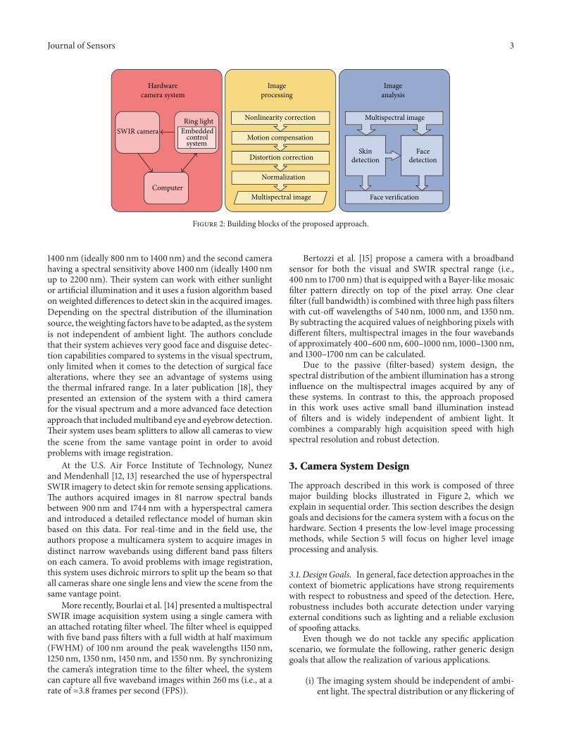
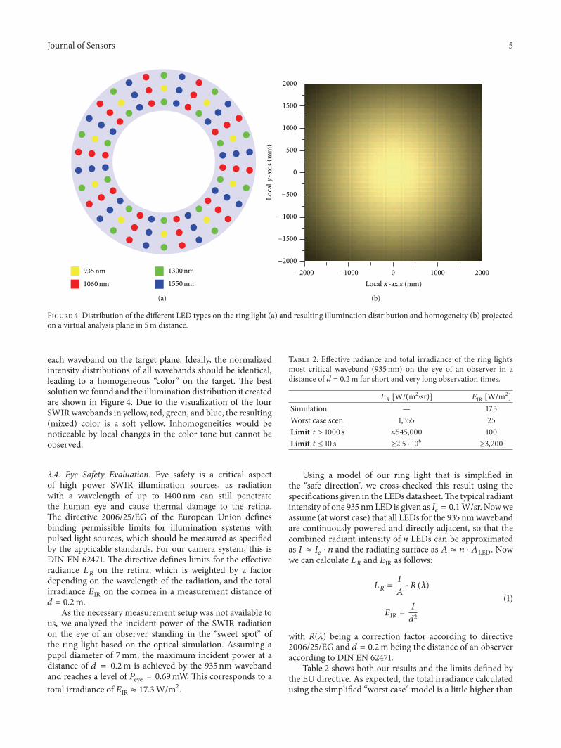
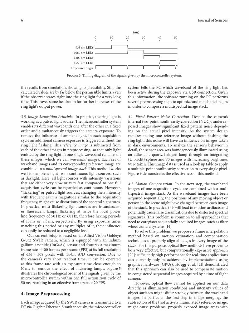
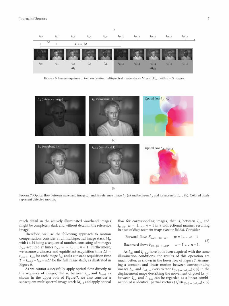
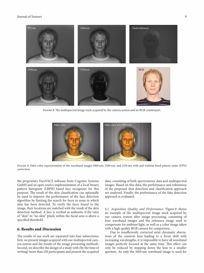
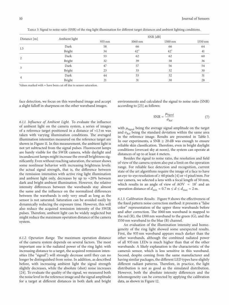
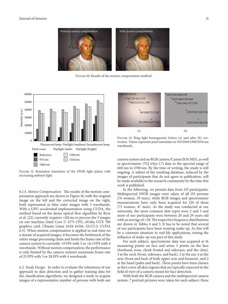
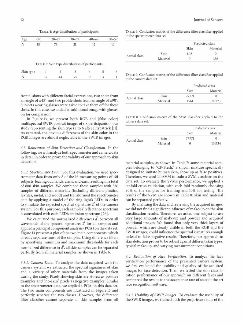
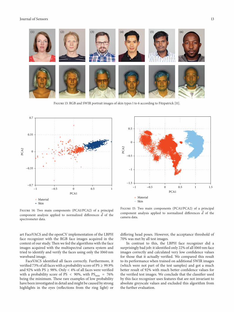
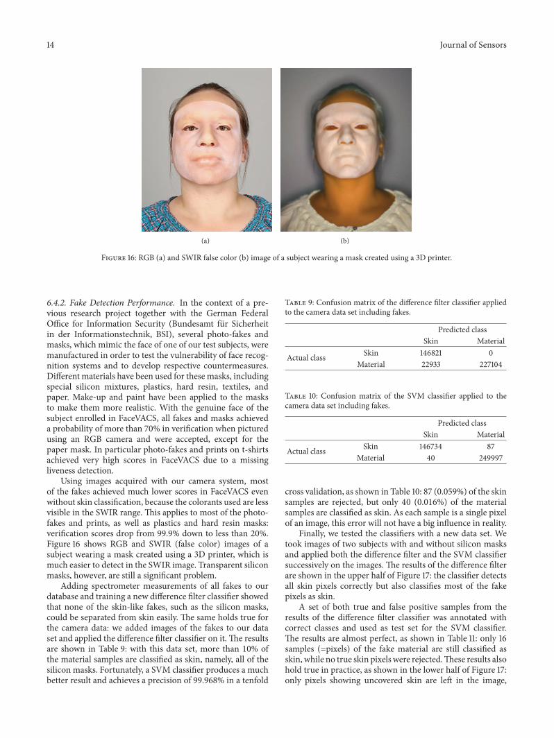
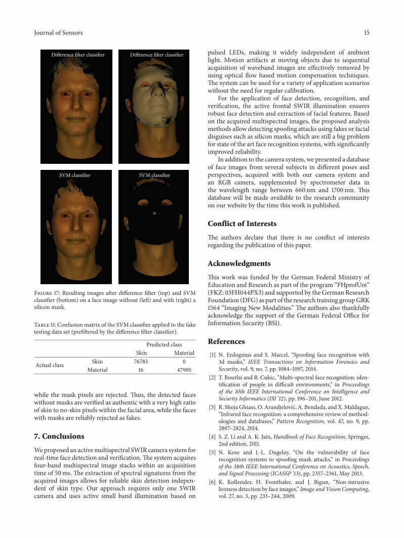

International Journal of
AerospaceEngineeringHindawi Publishing Corporationhttpwwwhindawicom Volume 2014
RoboticsJournal of
Hindawi Publishing Corporationhttpwwwhindawicom Volume 2014
Hindawi Publishing Corporationhttpwwwhindawicom Volume 2014
Active and Passive Electronic Components
Control Scienceand Engineering
Journal of
Hindawi Publishing Corporationhttpwwwhindawicom Volume 2014
International Journal of
RotatingMachinery
Hindawi Publishing Corporationhttpwwwhindawicom Volume 2014
Hindawi Publishing Corporation httpwwwhindawicom
Journal ofEngineeringVolume 2014
Submit your manuscripts athttpwwwhindawicom
VLSI Design
Hindawi Publishing Corporationhttpwwwhindawicom Volume 2014
Hindawi Publishing Corporationhttpwwwhindawicom Volume 2014
Shock and Vibration
Hindawi Publishing Corporationhttpwwwhindawicom Volume 2014
Civil EngineeringAdvances in
Acoustics and VibrationAdvances in
Hindawi Publishing Corporationhttpwwwhindawicom Volume 2014
Hindawi Publishing Corporationhttpwwwhindawicom Volume 2014
Electrical and Computer Engineering
Journal of
Advances inOptoElectronics
Hindawi Publishing Corporation httpwwwhindawicom
Volume 2014
The Scientific World JournalHindawi Publishing Corporation httpwwwhindawicom Volume 2014
SensorsJournal of
Hindawi Publishing Corporationhttpwwwhindawicom Volume 2014
Modelling amp Simulation in EngineeringHindawi Publishing Corporation httpwwwhindawicom Volume 2014
Hindawi Publishing Corporationhttpwwwhindawicom Volume 2014
Chemical EngineeringInternational Journal of Antennas and
Propagation
International Journal of
Hindawi Publishing Corporationhttpwwwhindawicom Volume 2014
Hindawi Publishing Corporationhttpwwwhindawicom Volume 2014
Navigation and Observation
International Journal of
Hindawi Publishing Corporationhttpwwwhindawicom Volume 2014
DistributedSensor Networks
International Journal of