Embed Size (px)
Citation preview
Research Article
Essa Ibrahim Essa*, Mshari A. Asker, and Fidan T. Sedeeq
Evaluating OADM network simulationand an overview based metropolitanapplication
https://doi.org/10.1515/jisys-2021-0194received September 23, 2021; accepted October 17, 2021
Abstract: Using optical add–drop multiplexer/remover multiplexer (OADM), it is possible to add or removewavelengths and change or route them through the various nodes and networks. At this moment, keyproblems in add–drop multiplexer (ADM) are the bandwidth, modulation format, and reuse wavelength. Inthis article, the Optisystem software simulation is used as a platform to design, test, and verify the methodapplied to the current work; the OADM is proposed based on the metro network to get distribution betweennodes over a transmission link; OADM analysis was presented with four channels (193.1, 193.2, 193.3, and193.4 THz) at total bandwidth of 1.6 Tb/s, none-return-to-zero (NRZ), and return to zero coding types.Experiment one shows that the average output power is −17.997 dBm, the average drop power is−17.997 dBm, and the average add power is −18.338 dBm, the average gain is −0.0429 dB, the average noisefigure is 0 dB, the average power input signal is 10.679 dBm, the average of power output signalis 10.633 dBm, and the average output optical signal-to-noise ratio (OSNR) is 0 dB, However, the secondexperiment shows that the average output power is −24.238 dBm, the average drop power is −24.288 dBm,and the average add power is −24.753 dBm, the average gain is −0.0417 dB, the average noise figure is 0 dB,average power input signal is 7.691 dBm, average of power output signal is 7.677 dBm, and the averageoutput OSNR 0 dB. The system supports four input channels, four add channels, four output channels, andfour drop channels. The results are acceptable after three spans of Solitons fiber with 600 km length,200 km for each span. Nonetheless, it is believed that it is well justified to adopt these schemes in thecurrent optical network with a low cost for overall expenditure.
Keywords: simulation, ADM, RZ, metro network, soliton fiber
1 Motivation
Nowadays, the Internet as an industry is based mainly on fiber. This leads to a vast range of misunder-standings, misconceptions, and errors when working with fiber-optic networks. Definitely, several attemptshave been made to assist a large number of individuals using the same transmission medium. This termrefers to the different multiplexing techniques used by hackers. Wave division multiplexing allows the useof the fibers’ broad bandwidth [1]. Due to the recent development of dense wavelength division multi-plexing (DWDM) systems, it is now possible to transmit hundreds of channels at a total capacity of morethan terabits per second. Another technique has been attempted in conjunction with wavelength division
* Corresponding author: Essa Ibrahim Essa, Networks Department, College of Computer Science and Information Technology,University of Kirkuk, Kirkuk, Iraq, e-mail: [email protected] A. Asker: Computer Science Department, College of Computer Science and Mathematics, Tikrit University, Tikrit, IraqFidan T. Sedeeq: Electrical Engineering Department, College of Engineering, University of Kirkuk, Kirkuk, Iraq
Journal of Intelligent Systems 2022; 31: 27–39
Open Access. © 2022 Essa Ibrahim Essa et al., published by De Gruyter. This work is licensed under the Creative CommonsAttribution 4.0 International License.
multiplexing the best performers on a multiprocessor and being one of the multiprocessor’s top weapons(optical add–drop multiplexer/remover multiplexer [OADM]) [2]. ADM is the most critical component of afiber-optic communication network. If the traffic is ascending, it may be bidirectional or unidirectional. InOADM, the wavelength modulation may be reduced or increased selectively. Wavelength coexists within afiber, resulting in channel concurrence. It then applies the same wavelength but in a different direction tothe same signal but an additional input, this time with the same signal but a different input [3].
An optical multiplexer’s primary purpose is to integrate multiple wavelengths into a single fiber. Whenused in conjunction with a multiplexer, it is evident that the spectrum contains two distinct wavelengths (orchannels). This enables the separation and addition of wavelengths separately. It is colloquially referred toas an add–drop demultiplexer, but when an optical wavelength is defined, it is referred to as a multiplexer.Although these units are small, monolithic integration will undoubtedly play a significant role in futuredesigns of smaller, lighter, and more affordable devices [4].
The discussion of an all-fiber unidirectional ring in the article is almost entirely confined to ring WDMnetworks. Each node in OADM subtracts a distinct wavelength, allowing for stage-by-stage wavelengthselection. The transmission uses longer data wavelengths, while reception uses shorter data wavelengths.Each OADM converts the data from the ring to an optical signal. Infrastructures are being strained to thebreaking point as bandwidth demands grow. Metros have been fitted with this capability to fulfil thisrequirement. Optical add/drop multiplexers are well suited for wavelength handling due to their abilityto connect and remove optical channels. Due to the OADM’s low-loss, low-cost passive systems, low-cost,and scalable technology enables a highly stable network with very little electricity consumption [5–7]. Thearticle is divided into four sections: one devoted to prior research on the topic, one to the proposal itself,one to a comparison, conclusion, and discussion, and one to two experiments.
2 OADM architecture
A conventional OADM comprises three components: an optical (multiplexer (MUX)/De-MUX) system forreconfiguring the paths between the (MUX/De-MUX) and a series of add–drop ports. A multiplexer is adevice that couples two or more wavelengths into a single fiber. A fiber patch panel or optical switches thatguide wavelengths to the optical (MUX) or drop ports can then reconfigure the system. The De-MUXs reversethe multiplexer’s behavior. They divide a fiber’s multiple wavelengths and send them to multiple fibers.“Add” refers to an OADM’s ability to adding one or more new wavelength channels to an existing multi-wavelength WDM signal. Although “delete” refers to dropping or removing one or more channels androuting those signals to a different network direction. OADM eliminates (drops) a wavelength from a groupof wavelengths in fiber, thus from traffic on that channel. It then adds a wavelength in the same direction asthe data flow but with different data materials [1].
3 Related studies
Many previous studies were conducted by many researchers in relation to OADM including Lee and Koh [8];they discuss a proposal of the hybrid ring-mesh network in survivable network communication by speci-fying a location for traffic demands. The difficulty lies in assigning each traffic demand to rings and meshsuch that the cost of ADM and DCS equipment’s required is minimized. Fishman et al. [9] state that thisOADM has shown to have a unique asymmetric bandwidth that could be used to optimally support 50 GHzDWDM transmissions with 10 Gb/s and 40 Gb/s DWDM spacing. Numerous OADMs accept 10 Gb/s RZ-OOKand 40 Gb/s DPSK signals with a reasonable penalty. Konishi et al. [10] propose and demonstrate awavelength- and time-selective reconfigurable optical add–drop multiplexer (ROADM) using time-fre-quency domain processing with equivalent 3.2 Tb/s (0.64 Tb/s five channels) and reconfigurability through
28 Essa Ibrahim Essa et al.
the MEMS optical switch switching operation. Chung and Mo [11] consider the routing and wavelengthassignment problem on synchronous optical network over WDM ring networks. To deal with the complexityof the problem, Udalcovs et al. [12] develop a combined system model that can be considered under thenext-generation optical network as a model for the future design of backbone networks. Zabir et al. [13]propose a novel method for dealing with crosstalk using an optical add–drop multiplexer based on fiberBragg gratings. The authors demonstrate through an analytical model that various parameters improvewhen their proposed OADM is used. Mahiuddin and Islam [14] develop an investigative model for lowcrosstalk in an OADM with a fiber Bragg grating and isolator. Syuhaimi Ab-Rahman [15] develop a design tocombine the operational concepts of (OADM) and an optical cross-connect (OXC). It is developed byanalyzing the shortcomings of existing devices and adding some superior features. Optical cross-connectadd drop multiplexer is introduced to increase the ring network’s survivability. Ibrahim Essa et al. [16]demonstrate the simulation of an architecture enabled by an optical coaster wavelength divisionmultiplexerthat satisfies reconfiguration requirements and enhances network security. Their architecture is truly scal-able in terms of efficiently handling additional wavelengths or nodes. Mohan and Anisha [17] demonstratehow to achieve full-duplex transmission of RoF using WDM and OADM, where WDM enables the transmis-sion of multiple signals over a long distance via a single-mode fiber and OADM enables the transmission ofboth downlink and uplink data via the same SMF. El-Naser et al. [18] have numerically and parametricallymodelled the high and best performance functions of optical add–drop multiplexers (OADMs) for ultrawidewavelength division multiplexing technique processed to handle bit rate either per link or per channel formultilink cables (20–120 links/core). According to Udalcovs and Bobrovs [19], energy-consuming pertransmitted bit could increase more than twofold whenWDM channels are added at the OADM/OXC station,compared to wavelengths transmitted over point-to-point fiber-optical links and then reduced at thereceiving node. Bajaj and colleagues [20] propose a work-based OADM that consists of three parts: initially,the DWDM network is modeled in OptiSystem (an optical simulating tool), and parameters such as opticalsignal-to-noise ratio (OSNR), jittering, chromatic dispersion, and bit error rate are obtained. These para-meters are used to train the feed-forward artificial neural network in the second phase. Bala and Dewra [21]investigate the presence of a ring-star-tree hybrid topology using OADM. They discover that at a transmis-sion power of −17 dBm, the hybrid network supports 32 and 128 users for the star and tree topologies,respectively. Miladic et al. [22] demonstrate the optical technologies that will help smart cities use sensorsand reliable optical infrastructure. Boubakri et al. [23] figure the relation between the 5 G networks based onthe optical networks to applications in smart cities.
The work contributions fall into many considerations like:(i) Overcoming group velocity dispersion (GVD) and self-phase modulation (SPM) phenomena using
solitons fiber as transmission link.(ii) Overcoming the reuse of wavelength in the optical network by using WDM systems.(iii) Applying this work to the metro optical network currently used by the Ministry of Communication in
the Republic of Iraq by designing two experiments with two different modulation codings.
4 Proposal methodology
There are several possible implementations of OADMs depending on the physical concept and the deployedoptical components. Besides the general use of (passive/active) optical components, this work presents anattempt to design and simulate a ring optical network based on OADM with some different fiber lengths,additional bandwidth, and advanced modulation format for overcoming some problems mentioned by theMinistry of Communication in the Republic of Iraq including the reuse wavelengths, bandwidth amount,network monitoring, and the addition of new nodes over fiber. Therefore, the current study aims at findingsolutions for these problems without re-changing the current infrastructure. It also attempts to add aunique wavelength and drop it from another node. Figure 1 shows the current work’s block diagram.
Evaluating OADM network 29
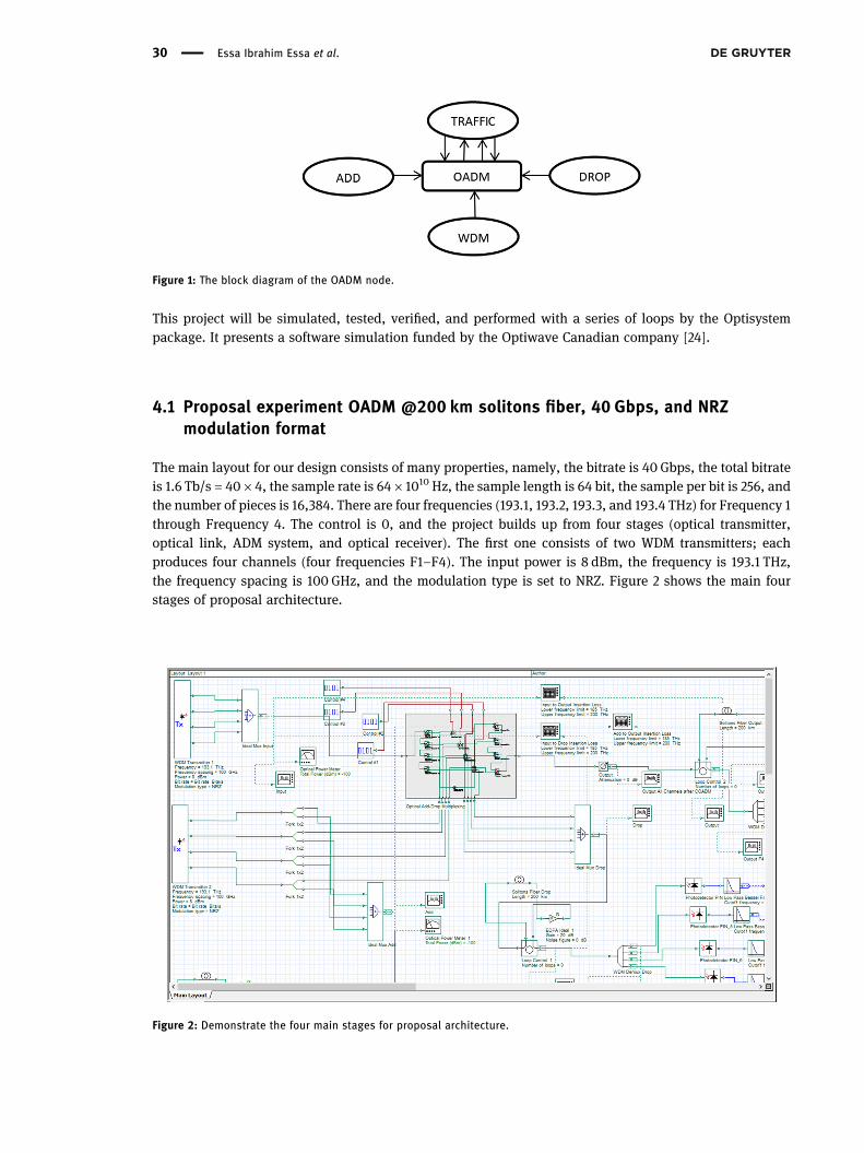
This project will be simulated, tested, verified, and performed with a series of loops by the Optisystempackage. It presents a software simulation funded by the Optiwave Canadian company [24].
4.1 Proposal experiment OADM @200 km solitons fiber, 40 Gbps, and NRZmodulation format
The main layout for our design consists of many properties, namely, the bitrate is 40 Gbps, the total bitrateis 1.6 Tb/s = 40 × 4, the sample rate is 64 × 1010 Hz, the sample length is 64 bit, the sample per bit is 256, andthe number of pieces is 16,384. There are four frequencies (193.1, 193.2, 193.3, and 193.4 THz) for Frequency 1through Frequency 4. The control is 0, and the project builds up from four stages (optical transmitter,optical link, ADM system, and optical receiver). The first one consists of two WDM transmitters; eachproduces four channels (four frequencies F1–F4). The input power is 8 dBm, the frequency is 193.1 THz,the frequency spacing is 100 GHz, and the modulation type is set to NRZ. Figure 2 shows the main fourstages of proposal architecture.
Figure 1: The block diagram of the OADM node.
Figure 2: Demonstrate the four main stages for proposal architecture.
30 Essa Ibrahim Essa et al.
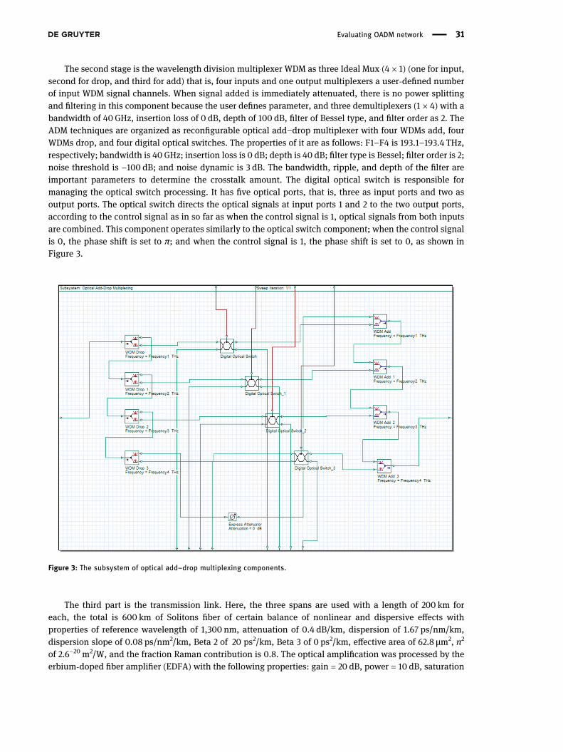
The second stage is the wavelength division multiplexer WDM as three Ideal Mux (4 × 1) (one for input,second for drop, and third for add) that is, four inputs and one output multiplexers a user-defined numberof input WDM signal channels. When signal added is immediately attenuated, there is no power splittingand filtering in this component because the user defines parameter, and three demultiplexers (1 × 4) with abandwidth of 40 GHz, insertion loss of 0 dB, depth of 100 dB, filter of Bessel type, and filter order as 2. TheADM techniques are organized as reconfigurable optical add–drop multiplexer with four WDMs add, fourWDMs drop, and four digital optical switches. The properties of it are as follows: F1–F4 is 193.1–193.4 THz,respectively; bandwidth is 40 GHz; insertion loss is 0 dB; depth is 40 dB; filter type is Bessel; filter order is 2;noise threshold is −100 dB; and noise dynamic is 3 dB. The bandwidth, ripple, and depth of the filter areimportant parameters to determine the crosstalk amount. The digital optical switch is responsible formanaging the optical switch processing. It has five optical ports, that is, three as input ports and two asoutput ports. The optical switch directs the optical signals at input ports 1 and 2 to the two output ports,according to the control signal as in so far as when the control signal is 1, optical signals from both inputsare combined. This component operates similarly to the optical switch component; when the control signalis 0, the phase shift is set to π; and when the control signal is 1, the phase shift is set to 0, as shown inFigure 3.
The third part is the transmission link. Here, the three spans are used with a length of 200 km foreach, the total is 600 km of Solitons fiber of certain balance of nonlinear and dispersive effects withproperties of reference wavelength of 1,300 nm, attenuation of 0.4 dB/km, dispersion of 1.67 ps/nm/km,dispersion slope of 0.08 ps/nm2/km, Beta 2 of 20 ps2/km, Beta 3 of 0 ps2/km, effective area of 62.8 µm2, n2
of 2.6−20 m2/W, and the fraction Raman contribution is 0.8. The optical amplification was processed by theerbium-doped fiber amplifier (EDFA) with the following properties: gain = 20 dB, power = 10 dB, saturation
Figure 3: The subsystem of optical add–drop multiplexing components.
Evaluating OADM network 31
power = 10 dB, noise figure = 0 dB, noise center frequency = 193.4 THz, noise bandwidth = 13 THz, and noisebins spacing = 125 GHz.
Finally, part four consists of 12 photodiodes of positive intensive negative (PIN) type with properties ofresponsivity of 1 A/W, the dark current of 10 mA, the sample rate of 3.2 × 10¹², and the thermal noise of1 × 10−22 W/Hz, and 12 low-pass Bessel filters with properties of cutoff frequency of 7.5 × 10⁹ Hz, insertionloss of 0 dB, depth of 100 dB, and order as (4). The mathematical model for the low-pass Bessel filter isshown in equations (1)–(6). The system behaviors are monitored by oscilloscopes, optical spectrum ana-lyzer, optical power meters, dual-port analyzer, and radio frequency spectrum analyzer.
( )( )
=H s α dB s
,N
0 (1)
( )=
!
⋅ !
d NN
22
,N0 (2)
( ) ∑=
=
B s d s ,NN
k
kk
0
(3)
( )
( )=
− !
⋅ ! − !
−
d N kk N k
22
,k N k (4)
⎜ ⎟⎛
⎝
⎞
⎠=
⋅s j f wf
,b
c(5)
( )≈ − ⋅ ≥w N N2 1 ln 2 for 10,b (6)
where insertion loss is α, the nth-order Bessel polynomial is the BN, it is the frequency that is set by the filtercutoff parameter, and wb is the 3 dB bandwidth, which can be estimated by using equation (6). For values ofN less than 10, a separate table is used to calculate the actual bandwidth.
4.2 Proposal experiment OADM @200 km solitons fiber, 40 Gbps, and return-to-zero (RZ) modulation format
In this experiment, the same components that were used in previous experiment, except the modulationtype in the WDM transmitter is set to RZ modulation format as a coding technique.
5 Output results and discussion
After simulating our designed proposal and performing a series of tests, the following results are obtainedand summarized in the following subsections.
5.1 Results of proposal experiment OADM @200 km solitons fiber, 40 Gbps, andNRZ modulation format
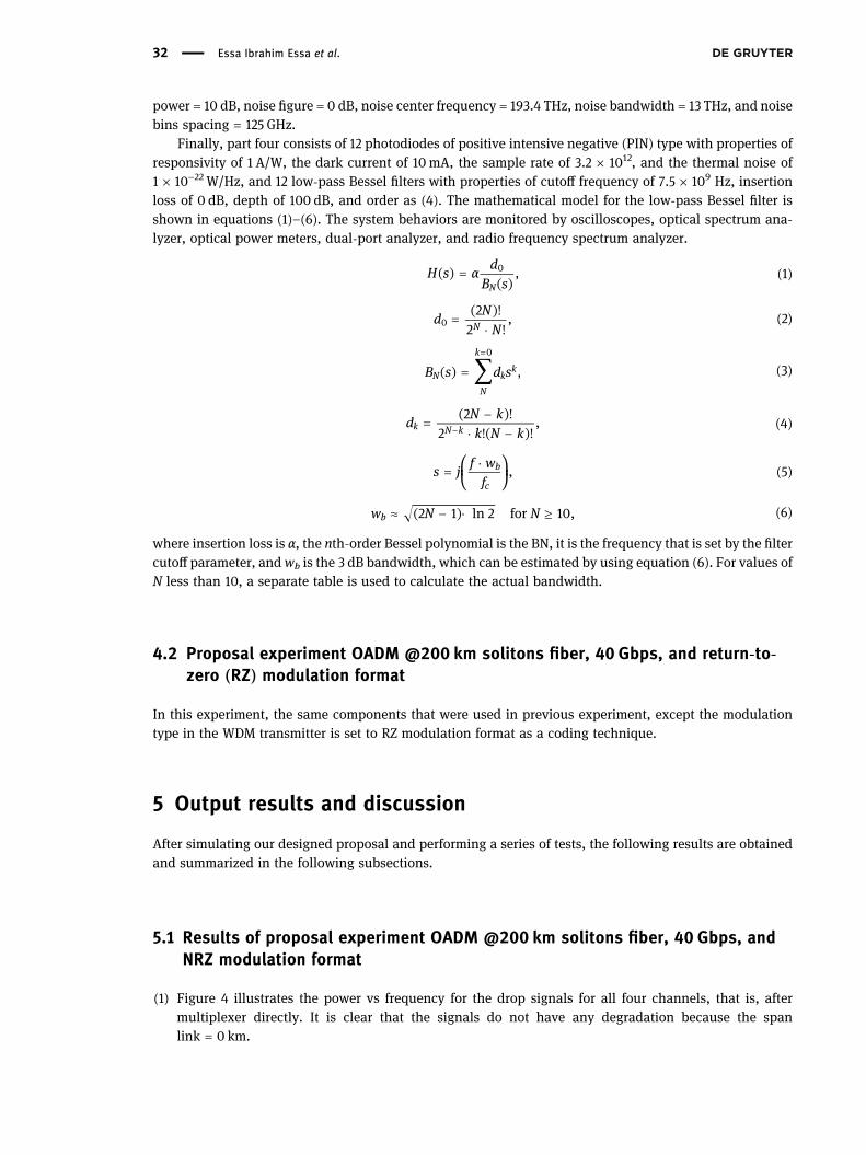
(1) Figure 4 illustrates the power vs frequency for the drop signals for all four channels, that is, aftermultiplexer directly. It is clear that the signals do not have any degradation because the spanlink = 0 km.
32 Essa Ibrahim Essa et al.
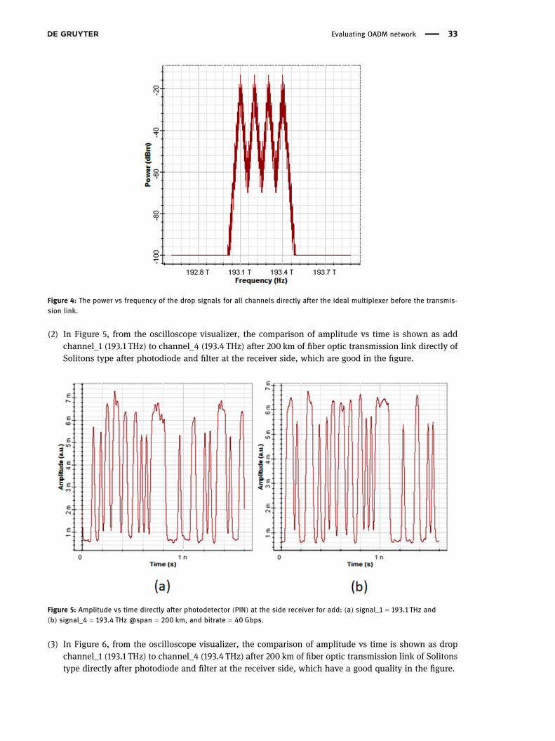
(2) In Figure 5, from the oscilloscope visualizer, the comparison of amplitude vs time is shown as addchannel_1 (193.1 THz) to channel_4 (193.4 THz) after 200 km of fiber optic transmission link directly ofSolitons type after photodiode and filter at the receiver side, which are good in the figure.
(3) In Figure 6, from the oscilloscope visualizer, the comparison of amplitude vs time is shown as dropchannel_1 (193.1 THz) to channel_4 (193.4 THz) after 200 km of fiber optic transmission link of Solitonstype directly after photodiode and filter at the receiver side, which have a good quality in the figure.
Figure 4: The power vs frequency of the drop signals for all channels directly after the ideal multiplexer before the transmis-sion link.
Figure 5: Amplitude vs time directly after photodetector (PIN) at the side receiver for add: (a) signal_1 = 193.1 THz and(b) signal_4 = 193.4 THz @span = 200 km, and bitrate = 40 Gbps.
Evaluating OADM network 33
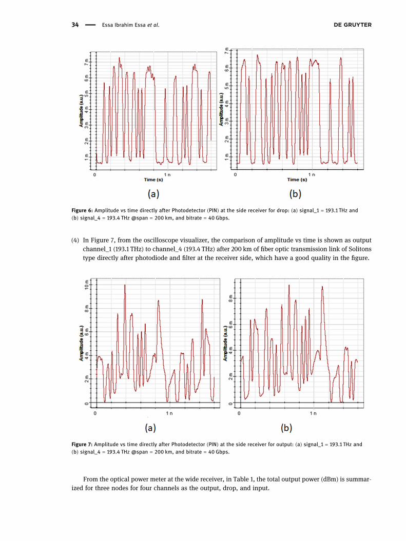
(4) In Figure 7, from the oscilloscope visualizer, the comparison of amplitude vs time is shown as outputchannel_1 (193.1 THz) to channel_4 (193.4 THz) after 200 km of fiber optic transmission link of Solitonstype directly after photodiode and filter at the receiver side, which have a good quality in the figure.
From the optical power meter at the wide receiver, in Table 1, the total output power (dBm) is summar-ized for three nodes for four channels as the output, drop, and input.
Figure 6: Amplitude vs time directly after Photodetector (PIN) at the side receiver for drop: (a) signal_1 = 193.1 THz and(b) signal_4 = 193.4 THz @span = 200 km, and bitrate = 40 Gbps.
Figure 7: Amplitude vs time directly after Photodetector (PIN) at the side receiver for output: (a) signal_1 = 193.1 THz and(b) signal_4 = 193.4 THz @span = 200 km, and bitrate = 40 Gbps.
34 Essa Ibrahim Essa et al.
From the dual-port WDM analyzer between multiplexer and demultiplexer, the signals are monitoredfrom end to end; Table 2 summarizes these values.
5.2 Results of proposal experiment OADM @200 km solitons fiber, 40 Gbps, andRZ modulation format
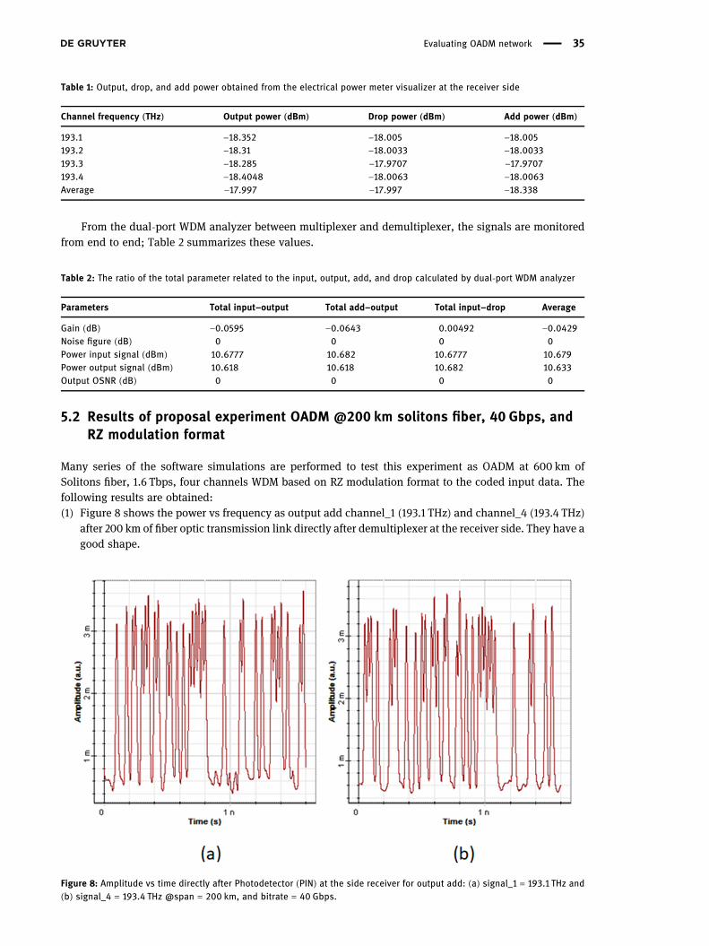
Many series of the software simulations are performed to test this experiment as OADM at 600 km ofSolitons fiber, 1.6 Tbps, four channels WDM based on RZ modulation format to the coded input data. Thefollowing results are obtained:(1) Figure 8 shows the power vs frequency as output add channel_1 (193.1 THz) and channel_4 (193.4 THz)
after 200 km of fiber optic transmission link directly after demultiplexer at the receiver side. They have agood shape.
Table 2: The ratio of the total parameter related to the input, output, add, and drop calculated by dual-port WDM analyzer
Parameters Total input–output Total add–output Total input–drop Average
Gain (dB) −0.0595 −0.0643 0.00492 −0.0429Noise figure (dB) 0 0 0 0Power input signal (dBm) 10.6777 10.682 10.6777 10.679Power output signal (dBm) 10.618 10.618 10.682 10.633Output OSNR (dB) 0 0 0 0
Figure 8: Amplitude vs time directly after Photodetector (PIN) at the side receiver for output add: (a) signal_1 = 193.1 THz and(b) signal_4 = 193.4 THz @span = 200 km, and bitrate = 40 Gbps.
Table 1: Output, drop, and add power obtained from the electrical power meter visualizer at the receiver side
Channel frequency (THz) Output power (dBm) Drop power (dBm) Add power (dBm)
193.1 −18.352 −18.005 −18.005193.2 −18.31 −18.0033 −18.0033193.3 −18.285 −17.9707 −17.9707193.4 −18.4048 −18.0063 −18.0063Average −17.997 −17.997 −18.338
Evaluating OADM network 35
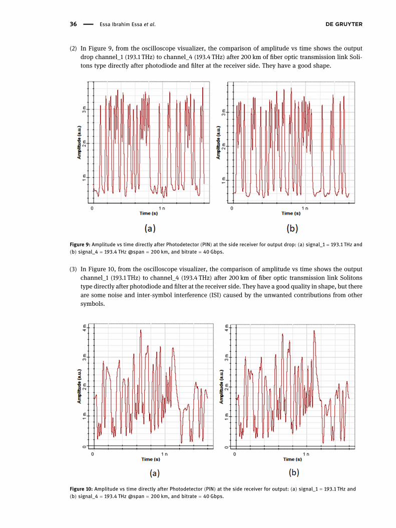
(2) In Figure 9, from the oscilloscope visualizer, the comparison of amplitude vs time shows the outputdrop channel_1 (193.1 THz) to channel_4 (193.4 THz) after 200 km of fiber optic transmission link Soli-tons type directly after photodiode and filter at the receiver side. They have a good shape.
(3) In Figure 10, from the oscilloscope visualizer, the comparison of amplitude vs time shows the outputchannel_1 (193.1 THz) to channel_4 (193.4 THz) after 200 km of fiber optic transmission link Solitonstype directly after photodiode and filter at the receiver side. They have a good quality in shape, but thereare some noise and inter-symbol interference (ISI) caused by the unwanted contributions from othersymbols.
Figure 9: Amplitude vs time directly after Photodetector (PIN) at the side receiver for output drop: (a) signal_1 = 193.1 THz and(b) signal_4 = 193.4 THz @span = 200 km, and bitrate = 40 Gbps.
Figure 10: Amplitude vs time directly after Photodetector (PIN) at the side receiver for output: (a) signal_1 = 193.1 THz and(b) signal_4 = 193.4 THz @span = 200 km, and bitrate = 40 Gbps.
36 Essa Ibrahim Essa et al.
From the dual-port WDM analyzer between multiplexer and demultiplexer, the signals are monitoredfrom end to end. Tables 3 and 4 summarize these values.
Table 5 summarizes the average parameters concluded from the two proposals with different modula-tion formats.
As shown in Table 5, the average values for the evaluation parameters for the two types of modulationformat are acceptable for this software simulation due to choosing suitable elements with their properties.
The applicability of these new results is tested for the current infrastructure used by the Ministry ofCommunications in the Republic of Iraq. In spite of being widely accepted, it suffers from some limitationsdue to polarization mode dispersion management. This is particularly important when investigating thethird-order dispersion. In contrast, this makes it possible to implement this work in smart cities. There arereasons to doubt these networks to overcome the nonlinearities problem and high bandwidth. As discussed,this is because the Solitons fiber is an attractive selection in the OADM networks.
Table 4: The total ratio for the input, output, and drop signals calculated by dual port WDM analyzer
Parameter Total input–output Total add–output Total input–drop Average
Gain (dB) −0.0359 −0.0625 −0.0266 −0.0417Noise figure (dB) 0 0 0 0Power input signal (dBm) 7.683 7.7098 7.683 7.691Power output signal (dBm) 7.647 7.647 7.709 7.677Output OSNR (dB) 0 0 0 0
Table 5: The average parameters obtained from two proposals
Parameter NRZ RZ
Output power (dBm) −17.997 −24.238Drop power (dBm) −17.997 −24.288Add power (dBm) −18.338 −24.753Gain (dB) −0.0429 −0.0417Noise figure (dB) 0 0Power input signal (dBm) 10.679 7.691Power output signal (dBm) 10.633 7.677Output OSNR (dB) 0 0
Table 3: The output power for add, drop, and output calculated by the electrical power meter analyzer
Channel frequency (THz) Output power (dBm) Drop power (dBm) Add power (dBm)
193.1 −24.7997 −24.4556 −24.2556193.2 −24.6989 −24.146 −24.146193.3 −24.6996 −24.2539 −24.2539193.4 −24.8116 −24.2944 −24.2944Average −24.238 −24.288 −24.753
Evaluating OADM network 37
6 Conclusion
The findings of this article can have the way for adopting the upgrading current optical infrastructure withlow cost of the overall system by eliminating the conversions of optical-to-electrical-to-optical and performthese conversions as optical–optical–optical. This is an important finding in the understanding of theswitching processes. The bandwidth, distance, and monitoring are important issues in the optical infra-structure. In this article, the evaluation of OADM-based metro network is evaluated. The presentation ofOADM is analyzed with four input channels (193.1, 193.2, 193.3, and 193.4 THz) at a total bandwidth of1.6 Tb/s of NRZ and RZ coding types. Experiment reveals the values of the average output power(−17.997 dBm), the average drop power (−17.997 dBm), and the average add power (−18.338 dBm), theaverage gain (−0.0429 dB), the average noise figure (0 dB), the average power input signal (10.679 dBm),the average of power output signal (10.633 dBm), the average output OSNR (0 dB). While the secondexperiment shows the average output power (−24.238 dBm), the average drop power (−24.288 dBm), theaverage add power (−24.753 dBm), the average gain (−0.0417 dB), the average noise figure (0 dB), theaverage power input signal (7.691 dBm), the average of power output signal (7.677 dBm), the average outputOSNR (0 dB). As the bandwidth and the transmission link increase, the monitoring nodes are used tomonitor the network using add–drop. So far, to overcome the GVD and SPM phenomena, we use EDFAis used with Solitons fiber. The system supports four add channels, four output channels, and four dropchannels. The results are acceptable and significant after three spans of Solitons fiber with 600 km length,200 km for each span.
Conflict of interest: Authors state no conflict of interest.
References
[1] Ramaswami R, Sivarajan KN. Optical networks: a practical perspective. 2nd ed. India: Elsevier; 2009.[2] Rani A, Singh Bhamrah M, Dewra S. Performance evaluation of the dense wavelength division multiplexing system using
reconfigurable optical add/drop multiplexer based on digital switches. Optical Quantum Electron. 2020;52(11):1–3.doi: 10.1007/s11082-020-02608-x.
[3] Ip J. Demultiplexer for next generation DWDM network. In: Nolan DA, ed. OSA Trends in Optics and Photonics, WDMComponents. Vol. 29. USA: Optical Society of America, DC; 1999. p. 34–41.
[4] Simmons JM. Optical Network design and planning. New York: Springer; 2014. ISBN 978-3-319-05227-4.[5] Maier M. Metropolitan area WDM networks an AWG based approach. USA: Springer Science; 2004. ISBN 978-1-4615-
0511-2.[6] Kr. Tripathi D, Singh P, Shukla NK, Dixit HK. Reconfigurable optical add and drop multiplexers a review. Electr Computer
Engineering: An Int J (ECIJ). March 2014;3(1):1–13. doi: 10.14810/Ecij.2014.31011.[7] Jiang Y, Zhang Z, Yang J, Han X, Xiao H, Ma W, et al. A flexible and reconfigurable optical add-drop multiplexer for mode
division multiplexing systems. IEEE Photonics Technol Lett. Dec. 15, 2020;32(24):1515–8. doi: 10.1109/LPT.2020.3033714.[8] Lee CY, Koh SJ. Assignment of ADM rings and DCS mesh in telecommunication network. Project report, Protocol
Engineering Center, ETRI, 161 Kajung Dong, Taejon, Korea; 2001. p. 305–350.[9] Fishman DA, Ying J, Liu X, Chandrasekhar S, Gnauck AH. Optical add/drop multiplexer with asymmetric bandwidth
allocation and dispersion compensation for hybrid 10-Gb/s and 40-Gb/s DWDM transmission. Conference Paper OpticalFiber Communication Conference Anaheim. California: Optical Society of America; March 5, 2006. OFC Poster Session(OWI) © 2006.
[10] Konishi T, Itoh R, Itoh K. Wavelength- and time-selective reconfigurable optical add/drop multiplexer using time-fre-quency domain processing. EURASIP J Adv Signal Process. 2010;2010:807521. doi: 10.1155/2010/807521.
[11] Chung J, Mo J. Optimal routing and wavelength assignment to minimize the number of SONET ADMs in WDM rings.Photonic Netw Commun. February 2011;21(1):13–20.
[12] Udalcovs A, Bobrovs V, Ivanovs G. Investigation of differently modulated optical signals transmission in HDWDM systems.Comput Technol Appl Academic J. 2011;2(9):801.
[13] Zabir S, Abawajy JH, Ahmed F, Kamruzaman J, Karim MA, Sarkar NI. Analysis of performance limitations in fiber bragggrating based optical add-drop multiplexer due to crosstalk. J Netw. Mar 2012;7(3):409–11. doi: 10.4304/jnw.7.3.409-411.
38 Essa Ibrahim Essa et al.
[14] Mahiuddin M, IslamMS. Analysis of performance limitations in fiber bragg grating based optical add-drop multiplexer dueto crosstalk. J Netw. March 2012;7(3):450–5.
[15] Syuhaimi Ab-Rahman M. Flexible topology migration in optical cross add and drop multiplexer in metropolitan ringnetwork. J Computer Sci. 2012;8(4):474–81. ISSN-1549-3636.
[16] Ibrahim Essa E, Ayied Ahmad A, Asker MA, Sedeeq FT. Transmission power optimization of high speed 32 channels × 12.8Tbps CWDM based on multi-span SSMF using RZ modulation format. Periodical Eng Nat Sci. 2019;7(3):1546–54.doi: 10.21533/pen.v7i3.
[17] Mohan A, Anisha AP. Full duplex transmission in RoF system using WDM and OADM technology. Int J Eng Res Technol(IJERT). January-2015;4(1):513–6. ISSN: 2278-0181.
[18] El-Naser A, Mohammed A, Nabih Zaki Rashed A, Eid MMA. Important role of optical add drop multiplexers (OADMs) withdifferent multiplexing techniques in optical communication networks; 2015. https://www.researchgate.net/publication/266862906.
[19] Udalcovs A, Bobrovs V. Energy efficiency in WDM fiber-optical links considering OADM/OXC nodes. Opt Commun.2016;359:102–8. doi: 10.1016/j.optcom.2015.09.061.
[20] Bajaj P, Goel AK, Singh H. Application of soft computing technique for optical add/drop multiplexer in terms of OSNR andoptical noise power. In 2016 3rd International Conference on Computing for Sustainable Global Development (INDIACom).India: IEEE; 31, October 2016. p. 1793–8.
[21] Bala A, Dewra S. Hybrid ring-star-tree topology with optical add drop multiplexer: cost effective and capacity enhance-ment. J Eng Sci Technol Rev. 2017;10(3):195–9.
[22] Miladic SD, Markovic GZ, Nonkovic NP. Optical technologies in support of the smart city concept. TEHNIKA-SAOBRACAJ.2020;67(2):209–15.
[23] Boubakri W, Abdallah W, Boudriga N. An optical wireless communication based 5G architecture to enable smart cityapplications. In 2018 20th, IEEE International Conference On Transparent Optical Networks (ICTON). Romania: IEEE; 2018.p. 1–6. doi: 10.1109/ICTON.2018.8473657.
[24] http://www.optiwave.com/.
Evaluating OADM network 39


![Untitled-2 [] · asker/ alan tÜrkiye'deí erzincan askeri alan asker/ aun ilx66r.0x erzincan ili n 258 s .karabekir m 3tðs astanesi is hpcabe yerlesim asker](https://img.pdfslide.net/doc/110x75/5fa25379b3e44e6a1361cfad/untitled-2-asker-alan-toerkiyede-erzincan-askeri-alan-asker-aun-ilx66r0x.jpg)