Embed Size (px)
Citation preview
Research ArticleExtracting UML Class Diagrams from Object-OrientedFortran: ForUML
Aziz Nanthaamornphong,1 Jeffrey Carver,2 Karla Morris,3 and Salvatore Filippone4
1Department of Information and Communication Technology, Prince of Songkla University, Phuket Campus,Phuket 83120, Thailand2Department of Computer Science, University of Alabama, Tuscaloosa, AL 35487, USA3Sandia National Laboratories, 7011 East Avenue, Livermore, CA 94550-9610, USA4Department of Civil and Computer Engineering, University of Rome ‘Tor Vergata’, Roma 00173, Italy
Correspondence should be addressed to Aziz Nanthaamornphong; [email protected]
Received 10 April 2014; Accepted 20 June 2014
Academic Editor: Selim Ciraci
Copyright © 2015 Aziz Nanthaamornphong et al. This is an open access article distributed under the Creative CommonsAttribution License, which permits unrestricted use, distribution, and reproduction in any medium, provided the original work isproperly cited.
Many scientists who implement computational science and engineering software have adopted the object-oriented (OO) Fortranparadigm. One of the challenges faced by OO Fortran developers is the inability to obtain high level software design descriptionsof existing applications. Knowledge of the overall software design is not only valuable in the absence of documentation, it can alsoserve to assist developers with accomplishing different tasks during the software development process, especially maintenance andrefactoring. The software engineering community commonly uses reverse engineering techniques to deal with this challenge. Anumber of reverse engineering-based tools have been proposed, but few of them can be applied to OO Fortran applications. Inthis paper, we propose a software tool to extract unified modeling language (UML) class diagrams from Fortran code. The UMLclass diagram facilitates the developers’ ability to examine the entities and their relationships in the software system.The extracteddiagrams enhance softwaremaintenance and evolution.The experiments carried out to evaluate the proposed tool show its accuracyand a few of the limitations.
1. Introduction
Computational research has been referred to as the thirdpillar of scientific and engineering research, along withexperimental and theoretical research [1]. Computationalscience and engineering (CSE) researchers develop softwareto simulate natural phenomena that cannot be studied exper-imentally or to process large amounts of data. CSE softwarehas a large impact on society as it is used by researchersto study critical problems in a number of important appli-cation domains, including weather forecasting, astrophysics,construction of new physical materials, and cancer research[2]. For example, US capabilities in science and engineeringare frequently called upon to address urgent challenges innational and homeland security, economic competitiveness,health care, and environmental protection [3]. Recently the
software engineering (SE) community has become moreinterested in the development of software for CSE research.
In this critical type of software, Fortran is still a verywidely used programming language [4]. Due to the growingcomplexity of the problems being addressed through CSE,the procedural programming style available in a languagelike Fortran 77 is no longer sufficient. Many developers haveapplied the object-oriented programming (OOP) paradigmto effectively implement the complex data structures requiredby CSE software. In the case of Fortran developers, thisOOP paradigm was first emulated following an object-basedapproach in Fortran 90/95 [5–7]. By including full supportfor OOP constructs, the Fortran 2003 language standardinfluenced the advent of several CSE packages [8–12].
One of the greatest challenges faced by CSE developersis the ability to effectively maintain their software over its
Hindawi Publishing CorporationScientific ProgrammingVolume 2015, Article ID 421816, 15 pageshttp://dx.doi.org/10.1155/2015/421816
2 Scientific Programming
generally long lifetime [13].This challenge implies high devel-opment and maintenance costs during a software system’slifetime. The difficulty of the maintenance process is affectedby at least three factors. First, most CSE developers arenot formally trained in SE. Second, some existing SE toolsare difficult to use in CSE development. In general, CSEdevelopers request tools to accommodate documentation,correctness testing, and aid in design software for testability.Unfortunately, most SE tools were not designed to be used inthe context of CSE development. Third, CSE software oftenlacks the formal documentation necessary to help developersunderstand its complex design. This lack of documentationpresents an even larger software maintenance challenge. Theobjective of this work is to provide tool support for automat-ically extracting UML class diagrams fromOO Fortran code.
To address this objective, we developed and evaluated theForUML tool. ForUML uses a reverse engineering approachto transform Fortran source code into UML models. Toensure flexibility, our solution uses a Fortran parser that doesnot depend on any specific Fortran compiler and generatesoutput in the XMLMetadata Interchange (XMI) format. Thetool then displays the results of the analysis (the UML classdiagram) using the ArgoUML (http://argouml.tigris.org/)modeling tool. We evaluated the accuracy of ForUML usingfive CSE software packages that use object-oriented featuresfrom the Fortran 95, 2003, and 2008 compiler standards.Thispaper extends the workshop paper [14] by providing morebackground information and more details on the transfor-mation process in ForUML. Additionally, this paper includesa discussion of the audience feedback during the Workshopon Software Engineering for High Performance Computing inComputational Science and Engineering (SE-HPCCSE’13).
The contributions of this paper are as follows:
(i) the ForUML tool thatwill helpCSEdevelopers extractUML design diagrams from OO Fortran code toenable them make good decisions about softwaredevelopment and maintenance tasks;
(ii) description of the transformation process used todevelop ForUML, which may help other tool authorscreate tools for the CSE community;
(iii) the results of the evaluation and our experiences usingForUML on real CSE projects to highlight its benefitsand limitations;
(iv) workshop feedback that should help SE developpractices and tools that are suitable for use in the CSEdomain.
The rest of this paper is organized as follows. Section 2provides the background concepts related to this work.Section 3 presents ForUML. Section 4 describes the evalua-tion and our experiences with ForUML. Section 5 discussesthe evaluation results and limitations of ForUML. Finally,Section 6 draws conclusions and presents future work.
2. Related Work
This section first describes important CSE characteristics thatimpact the development of tool support. Next, it presents
two important concepts used in the development of ForUML,reverse engineering and OO Fortran. Finally, because one ofthe benefits of using ForUML is the ability to recognize andmaintain design patterns, the last subsection provides somebackground on design patterns.
2.1. Important CSE Characteristics. This section highlightsthree characteristics of CSE software development that dif-ferentiate it from traditional software development. First,CSE developers typically have a strong background in thetheoretical science but often do not have formal trainingabout SE techniques that have proved successful in othersoftware areas. More specifically, because the complexity ofthe problems addressed by CSE generally requires a domainexpert (e.g., a Ph.D. in physics or biology) to even understandthe problem, and that domain expert generally must learnhow to develop software [15]. Wilson [16] stated that one ofthe reasons why scientists tend to be less effective program-mers is that they do not have the time to learn yet anotherprogramming language and software tool. Furthermore, theCSE culture, including most funding agencies, tends to viewsoftware as the means to a new scientific discovery ratherthan as a CSE instrument that must be carefully engineered,maintained, and extended to enable novel science.
Second, some SE tools are difficult to use in a CSE devel-opment environment [17]. CSE applications are generallydeveloped with software tools that are crude compared tothose used today in the commercial sector. Researchers andscientists seek easy-to-use software that enables analysis ofcomplex data and visualization of complicated interactions.Consequently, CSE developers often have trouble identifyingand using the most appropriate SE techniques for theirwork, in particular as it relates to reverse engineering tasks.Scientists interested in scientific research cannot spend mostof their time understanding and using complex softwaretools. The limited interoperability of the tools and theircomplexity are major obstructions to their adaptation bythe CSE community. For example, Storey noted that CSEdevelopers who lack formal SE training need help withprogram comprehension when they are developing complexapplications [18]. To address this problem, the SE communitymust develop tools that satisfy the needs of CSE developers.These tools must allow the developers to easily performimportant reverse engineering tasks. More specifically, avisualization-based tool is appropriate for program compre-hension in complex object-oriented applications [19].
Third, CSE software typically lacks adequate develop-ment-oriented documentation [20]. In fact, documentationfor CSE software often exists only in the form of subroutinelibrary documentation. This documentation is usually quiteclear and sufficient for library users, who treat the libraryas a black box, but not sufficient for developers who needto understand the library in enough detail to maintain it.The lack of design documentation in particular leads tomultiple problems. Newcomers to a project must invest alot of effort to understand the code. There is an increasedrisk of failure when developers of related systems cannotcorrectly understand how to interact with the subject system.
Scientific Programming 3
In addition, the lack of documentationmakes refactoring andmaintenance difficult and error prone. CSE software typicallyevolves over many years and involves multiple developers[21], as functionality and capabilities are added or extended[22]. The developers need to be able to determine whetherthe evolved software deviates from the original design intent.To ease this process, developers need tools that help themidentify changes that affect the design and determinewhetherthose changes have undesired effects on design integrity.The availability of appropriate design documentation canreduce the likelihood of poor choices during themaintenanceprocess.
2.2. Reverse Engineering. Reverse engineering is a methodthat transforms source code into a model [23]. ForUMLbuilds upon and expands some existing reverse engineeringwork. The Dagstuhl middle metamodel(DMM) is a schemafor describing the static structure of source code [24].DMM supports reverse engineering by representing modelsextracted from source code written in most common OOPlanguages. We applied the idea of DMM to OO Fortran.
The transformation process in ForUML is based on theXMI format, which provides a standard method of mappingan object model into XML. XMI is an open standard thatallows developers and software vendors to create, read,manage, and generate XMI tools. Transforming the model(Fortran code) to XMI requires use of themodel driven archi-tecture (MDA) technology [25], a modeling standard devel-oped by the object management group (OMG) [26]. MDAaims to increase productivity and reuse by using separationof concerns and abstraction. A platform independent model(PIM) is an abstract model that contains the information todrive one ormore platform specificmodels (PSMs), includingsource code, data definition language (DDL), XML, andother outputs specific to the target platform. MDA definestransformations that map from PIMs to PSMs.
The basic idea of using an XMI file to maintain the meta-data for UML diagrams was drawn from four reverse engi-neering tools. Alalfi et al. developed two tools that use XMIto maintain the metadata for the UML diagrams: a tool thatgenerates UML sequence diagrams for web application code[27] and a tool to create UML-entity relationship diagramsfor the structured query language (SQL) [28]. Similarly,Korshunova et al. [29] developedCPP2XMI to extract variousUML diagrams from C++ source code. CPP2XMI generatesan XMI document that describes the UML diagram, whichis then displayed graphically by DOT (part of the Graphvizframework) [30]. Duffy and Malloy [31] created libthorin, atool to convert C++ source code into UML diagrams. Prior toconverting an XMI document into a UML diagram, libthorinrequires developers to use a third party compiler to compilecode into the DWARF (http://www.dwarfstd.org/), which is adebugging file format used to support source level debugging.In terms of Fortran, DWARF only supports Fortran 90, whichdoes not include all object-oriented features. This limitationmay cause compatibility problems with different Fortrancompilers. Conversely, ForUML is compiler independent andable to generate UML for all types of OO Fortran code.
Doxygen is a documentation tool that can use Fortrancode to generate either a simple, textual representation withprocedural interface information or a graphical represen-tation. The only OOP class relationship Doxygen supportsis inheritance. With respect to our goals, Doxygen has twoprimary limitations. First, it does not support all OOPfeatures within Fortran (e.g., type-bound procedures andcomponents). Second, the diagrams generated by Doxygenonly include class names and class relationships but do notcontain other important information typically included inUML class diagrams (e.g., methods, properties). Our workexpands upon Doxygen by adding support for OO Fortranand by generating UML diagrams that include all relevantinformation about the included classes (e.g., properties,methods, and signatures).
There are a number of available tools (both open sourceand commercial) that claim to transform OO code intoUML diagrams (e.g., Altova UModel, Enterprise Architect,StarUML, and ArgoUML). However, in terms of our work,these tools do not supportOOFortran. Although they cannotdirectly create UML diagrams from OO Fortran code, mostof these tools are able to import themetadata describingUMLdiagrams (i.e., the XMI file) and generate the correspondingUML diagrams. ForUML takes advantages of this featureto display the UML diagrams described by the XMI files itgenerates from OO Fortran code.
This previous work has contributed significantly to thereverse engineering tools of traditional software. ForUMLspecifically offers a method to reverse engineering codeimplemented with modern Fortran, including features in theFortran 2008 standard. Moreover, the tool was deliberatelydesigned to support important features of Fortran, such ascoarrays, procedure overloading, and operator overloading.
2.3. Object-Oriented Fortran. Fortran is an imperative pro-gramming language. Traditionally, Fortran code has beendeveloped through a procedural programming approach thatemphasizes the procedures and subroutines in a programrather than the data. A number of studies discuss approachesfor expressing OOP principles in Fortran 90/95. For example,Decyk described how to express the concepts of data encapsu-lation, function overloading, classes, objects, and inheritancein Fortran 90 [6, 7, 32]. Moreover, several authors havedescribed the use and syntax of OO features in Fortran 2003[33–35]. Table 1 presents important Fortran-specific termsalong with their OOP equivalent and some examples ofFortran keywords.
The Fortran 2003 compiler standard added support forOOP, including the following OOP principles: dynamicand static polymorphism, inheritance, data abstraction, andencapsulation. Currently, a number of Fortran compiler ven-dors support all (or almost all) of the OOP features includedin the Fortran 2003 standard. These compilers include [36]
(i) NAG (http://www.nag.com/);(ii) GNU Fortran (http://gcc.gnu.org/fortran/);(iii) IBMXL Fortran (http://www-142.ibm.com/software/
products/us/en/fortcompfami/);
4 Scientific Programming
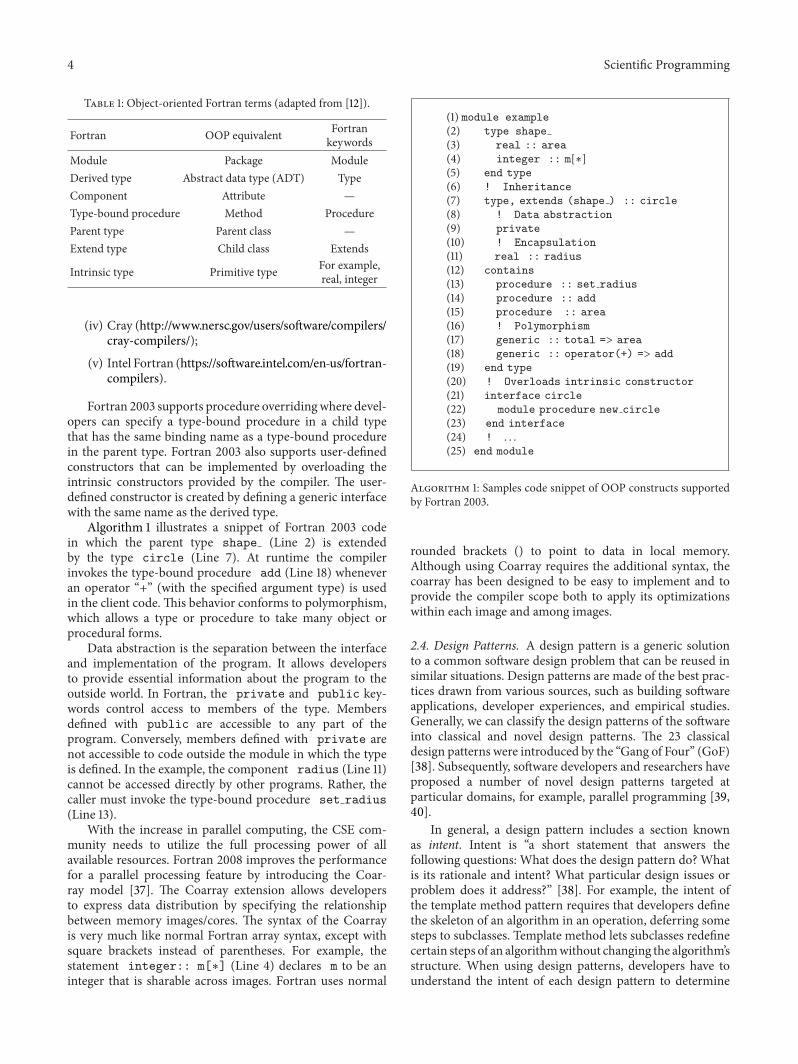
Table 1: Object-oriented Fortran terms (adapted from [12]).
Fortran OOP equivalent Fortrankeywords
Module Package ModuleDerived type Abstract data type (ADT) TypeComponent Attribute —Type-bound procedure Method ProcedureParent type Parent class —Extend type Child class Extends
Intrinsic type Primitive type For example,real, integer
(iv) Cray (http://www.nersc.gov/users/software/compilers/cray-compilers/);
(v) Intel Fortran (https://software.intel.com/en-us/fortran-compilers).
Fortran 2003 supports procedure overridingwhere devel-opers can specify a type-bound procedure in a child typethat has the same binding name as a type-bound procedurein the parent type. Fortran 2003 also supports user-definedconstructors that can be implemented by overloading theintrinsic constructors provided by the compiler. The user-defined constructor is created by defining a generic interfacewith the same name as the derived type.
Algorithm 1 illustrates a snippet of Fortran 2003 codein which the parent type shape (Line 2) is extendedby the type circle (Line 7). At runtime the compilerinvokes the type-bound procedure add (Line 18) wheneveran operator “+” (with the specified argument type) is usedin the client code. This behavior conforms to polymorphism,which allows a type or procedure to take many object orprocedural forms.
Data abstraction is the separation between the interfaceand implementation of the program. It allows developersto provide essential information about the program to theoutside world. In Fortran, the private and public key-words control access to members of the type. Membersdefined with public are accessible to any part of theprogram. Conversely, members defined with private arenot accessible to code outside the module in which the typeis defined. In the example, the component radius (Line 11)cannot be accessed directly by other programs. Rather, thecaller must invoke the type-bound procedure set radius(Line 13).
With the increase in parallel computing, the CSE com-munity needs to utilize the full processing power of allavailable resources. Fortran 2008 improves the performancefor a parallel processing feature by introducing the Coar-ray model [37]. The Coarray extension allows developersto express data distribution by specifying the relationshipbetween memory images/cores. The syntax of the Coarrayis very much like normal Fortran array syntax, except withsquare brackets instead of parentheses. For example, thestatement integer:: m[∗] (Line 4) declares m to be aninteger that is sharable across images. Fortran uses normal
(1) module example
(2) type shape
(3) real :: area
(4) integer :: m[∗]
(5) end type
(6) ! Inheritance
(7) type, extends (shape ) :: circle
(8) ! Data abstraction
(9) private
(10) ! Encapsulation
(11) real :: radius
(12) contains
(13) procedure :: set radius
(14) procedure :: add
(15) procedure :: area
(16) ! Polymorphism
(17) generic :: total => area
(18) generic :: operator(+) => add
(19) end type
(20) ! Overloads intrinsic constructor
(21) interface circle
(22) module procedure new circle
(23) end interface
(24) ! . . .
(25) end module
Algorithm 1: Samples code snippet of OOP constructs supportedby Fortran 2003.
rounded brackets () to point to data in local memory.Although using Coarray requires the additional syntax, thecoarray has been designed to be easy to implement and toprovide the compiler scope both to apply its optimizationswithin each image and among images.
2.4. Design Patterns. A design pattern is a generic solutionto a common software design problem that can be reused insimilar situations. Design patterns are made of the best prac-tices drawn from various sources, such as building softwareapplications, developer experiences, and empirical studies.Generally, we can classify the design patterns of the softwareinto classical and novel design patterns. The 23 classicaldesign patterns were introduced by the “Gang of Four” (GoF)[38]. Subsequently, software developers and researchers haveproposed a number of novel design patterns targeted atparticular domains, for example, parallel programming [39,40].
In general, a design pattern includes a section knownas intent. Intent is “a short statement that answers thefollowing questions: What does the design pattern do? Whatis its rationale and intent? What particular design issues orproblem does it address?” [38]. For example, the intent ofthe template method pattern requires that developers definethe skeleton of an algorithm in an operation, deferring somesteps to subclasses. Template method lets subclasses redefinecertain steps of an algorithmwithout changing the algorithm’sstructure. When using design patterns, developers have tounderstand the intent of each design pattern to determine
Scientific Programming 5
whether the design pattern could provide a good solution toa given problem.
Several researchers have proposed design patterns forcomputational software implemented with Fortran. Forexample, Weidmann [41] implemented design patterns toenable sparse matrix computations on NVIDIA GPUs. Theythen evaluated the benefits of the implementation andreported that the design patterns provided a high level ofmaintainability and performance. Rouson et al. [12] pro-posed three new design patterns, called multiphysics designpatterns, to implement the differential equations, which areintegrated into multiphysics and numerical software. Thesenew design patterns include the semidiscrete, surrogate andtemplate class patterns. Markus demonstrated how somewell-known design patterns could be implemented in Fortran90, 95, and 2003 [42, 43]. Similarly, Decyk et al. [4] proposedthe factory pattern in Fortran 95 based on CSE software.These researchers presented the proposed pattern implemen-tation in their particle-in-cell (PIC) methods [44] in plasmasimulation software. Decyk and Gardner [45] also describeda way to implement the strategy, template, abstract factory,and facade patterns in Fortran 90/95.
3. ForUML
This section describes the rationale and benefits of developingForUML and details the transformation process used byForUML.
3.1. The Need for ForUML. TheCSE characteristics describedin Section 2.1 indicate that CSE developers could benefit froma tool that creates systemdocumentationwith little effort.TheSE community typically uses reverse engineering to addressthis problem.
Although there are a number of reverse engineering tools[46] (see Section 2.2), those tools that can be applied to OOFortran do not provide the full set of documentation requiredby developers.Therefore, we identified the need for a tool thatautomatically reverses engineers OO Fortran code into thenecessary UML design documentation.
This work is primarily targeted at CSE developers whodevelop OO Fortran. The ForUML tool will provide thefollowing benefits to the CSE community.
(1) The extracted UML class diagrams should supportsoftware maintenance and evolution and help main-tainers ensure that the original design intentions aresatisfied.
(2) The developers can use the UML diagrams to illus-trate software design concepts to their teammembers.In addition, UML diagrams can help developers visu-ally examine relationships among objects to identifycode smells [47] in software being developed.
(3) Because SE tools generally improve productivity,ForUML can reduce the training time and learningcurve required for applying SE practices in CSE soft-ware development. For instance, ForUML will helpdevelopers perform refactoring activities by allowing
Module
Procedure
Type
Component
Type-bound procedure
Statement Argument
Base type
0..∗
0..∗
0..∗
0..∗
0..∗
0..∗
0..∗
0..∗
Figure 1: The Fortran model.
them to evaluate the results of refactoring usingthe UML diagrams rather than inspecting the codemanually.
Since Fortran 2003 provides all of the concepts of OOP,tools like ForUML can help to place Fortran and other OOPprogram languages on equal levels.
3.2. Transformation Process. The primary goal of ForUMLis to reverse engineering UML class diagrams from Fortrancode. By extracting a set of source files, it builds a collectionof objects associated with syntactic entities and relations.Object-based features were first introduced in the Fortran90 language standard. Accordingly, ForUML supports allversions of Fortran 90 and later, which encompasses mostplatforms and compiler vendors. We implemented ForUMLusing Java Platform SE6 so that it could run on any clientcomputing systems.
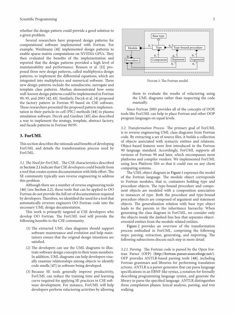
The UML object diagram in Figure 1 expresses the modelof the Fortran language. The module object correspondsto Fortran modules, that is, containers holding type andprocedure objects. The type-bound procedure and compo-nent objects are modeled with a composition associationto instances of type. Both the procedure and type-boundprocedure objects are composed of argument and statementobjects. The generalization relation with base type objectleads to the parents in the inheritance hierarchy. Whengenerating the class diagram in ForUML, we consider onlythe objects inside the dashed-line box that separates object-oriented entities from the module-related entities.
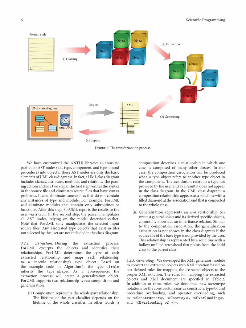
Figure 2 provides an overview of the transformationprocess embodied in ForUML, comprising the followingsteps: parsing, extraction, generating, and importing. Thefollowing subsections discuss each step in more detail.
3.2.1. Parsing. The Fortran code is parsed by the Open For-tran Parser (OFP) (http://fortran-parser.sourceforge.net/).OFP provides ANTLR-based parsing tools [48], includingFortran grammars and libraries for performing translationactions. ANTLR is a parser generator that can parse languagespecifications in an EBNF-like syntax, a notation for formallydescribing programming language syntax, and generate thelibrary to parse the specified language. ANTLR distinguishesthree compilation phases: lexical analysis, parsing, and treewalking.
6 Scientific Programming
XMI
Object
Export
Object Object
Object Object
Object
Object
Object
Object
Fortran code
UML class diagram
ArgoUML
(4) Import
(1) Parsing
(2) Extraction
(3) Generating
Figure 2: The transformation process.
We have customized the ANTLR libraries to translateparticular AST nodes (i.e., type, component, and type-boundprocedure) into objects. These AST nodes are only the basicelements ofUMLclass diagrams. In fact, aUMLclass diagramincludes classes, attributes, methods, and relations. The pars-ing actions include two steps.The first step verifies the syntaxin the source file and eliminates source files that have syntaxproblems. It also eliminates source files that do not containany instances of type and module. For example, ForUMLwill eliminate modules that contain only subroutines orfunctions. After this step, ForUML reports the results to theuser via a GUI. In the second step, the parser manipulatesall AST nodes, relying on the model described earlier.Note that ForUML only manipulates the selected inputsource files. Any associated type objects that exist in filesnot selected by the user are not included in the class diagram.
3.2.2. Extraction. During the extraction process,ForUML excerpts the objects and identifies theirrelationships. ForUML determines the type of eachextracted relationship and maps each relationshipto a specific relationship’s type object. Based onthe example code in Algorithm 1, the type circleinherits the type shape. As a consequence, theextraction process will create a generalization object.ForUML supports two relationship types: composition andgeneralization.
(i) Composition represents the whole-part relationship.The lifetime of the part classifier depends on thelifetime of the whole classifier. In other words, a
composition describes a relationship in which oneclass is composed of many other classes. In ourcase, the composition association will be producedwhen a type object refers to another type object inthe component. The association refers to a type notprovided by the user and as a result it does not appearin the class diagram. In the UML class diagram, acomposition relationship appears as a solid line with afilled diamond at the association end that is connectedto the whole class.
(ii) Generalization represents an is-a relationship be-tween a general object and its derived specific objects,commonly known as an inheritance relation. Similarto the composition association, the generalizationassociation is not shown in the class diagram if thesource file of the base type is not provided by the user.This relationship is represented by a solid line with ahollow unfilled arrowhead that points from the childclass to the parent class.
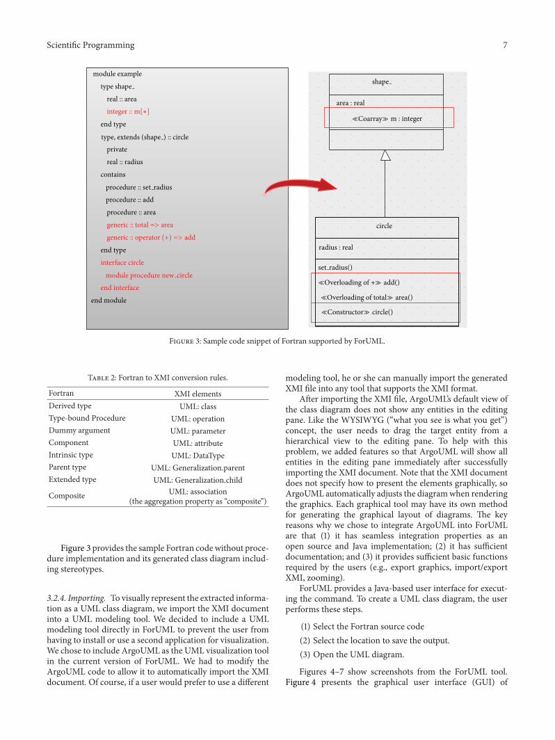
3.2.3. Generating. We developed the XMI generator moduleto convert the extracted objects into XMI notation based onour defined rules for mapping the extracted objects to theproper XMI notation. The rules for mapping the extractedobjects and XMI document are specified in Table 2.In addition to these rules, we developed new stereotypenotations for the constructor, coarray constructs, type-boundprocedure overloading, and operator overloading, suchas ≪Constructor≫, ≪Coarray≫, ≪Overloading≫,and ≪Overloading of +≫.
Scientific Programming 7
shape
area : real
m : integer
circle
≪Constructor≫ circle()
≪Overloading of total≫ area()
≪Overloading of +≫ add()
set radius()
module example
real :: area
end type
private
real :: radius
contains
end type
interface circle
procedure :: add
procedure :: area
end interface
end module
integer :: m[∗]
type shape
procedure :: set radius
generic :: total => area
module procedure new circle
type, extends (shape ) :: circle
generic :: operator (+) => addradius : real
≪Coarray≫
Figure 3: Sample code snippet of Fortran supported by ForUML.
Table 2: Fortran to XMI conversion rules.
Fortran XMI elementsDerived type UML: classType-bound Procedure UML: operationDummy argument UML: parameterComponent UML: attributeIntrinsic type UML: DataTypeParent type UML: Generalization.parentExtended type UML: Generalization.child
Composite UML: association(the aggregation property as “composite”)
Figure 3 provides the sample Fortran code without proce-dure implementation and its generated class diagram includ-ing stereotypes.
3.2.4. Importing. To visually represent the extracted informa-tion as a UML class diagram, we import the XMI documentinto a UML modeling tool. We decided to include a UMLmodeling tool directly in ForUML to prevent the user fromhaving to install or use a second application for visualization.We chose to include ArgoUML as the UML visualization toolin the current version of ForUML. We had to modify theArgoUML code to allow it to automatically import the XMIdocument. Of course, if a user would prefer to use a different
modeling tool, he or she can manually import the generatedXMI file into any tool that supports the XMI format.
After importing the XMI file, ArgoUML’s default view ofthe class diagram does not show any entities in the editingpane. Like the WYSIWYG (“what you see is what you get”)concept, the user needs to drag the target entity from ahierarchical view to the editing pane. To help with thisproblem, we added features so that ArgoUML will show allentities in the editing pane immediately after successfullyimporting the XMI document. Note that the XMI documentdoes not specify how to present the elements graphically, soArgoUML automatically adjusts the diagramwhen renderingthe graphics. Each graphical tool may have its own methodfor generating the graphical layout of diagrams. The keyreasons why we chose to integrate ArgoUML into ForUMLare that (1) it has seamless integration properties as anopen source and Java implementation; (2) it has sufficientdocumentation; and (3) it provides sufficient basic functionsrequired by the users (e.g., export graphics, import/exportXMI, zooming).
ForUML provides a Java-based user interface for execut-ing the command. To create a UML class diagram, the userperforms these steps.
(1) Select the Fortran source code(2) Select the location to save the output.(3) Open the UML diagram.
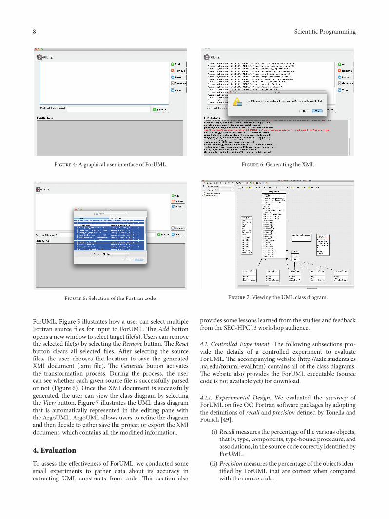
Figures 4–7 show screenshots from the ForUML tool.Figure 4 presents the graphical user interface (GUI) of
8 Scientific Programming
Figure 4: A graphical user interface of ForUML.
Figure 5: Selection of the Fortran code.
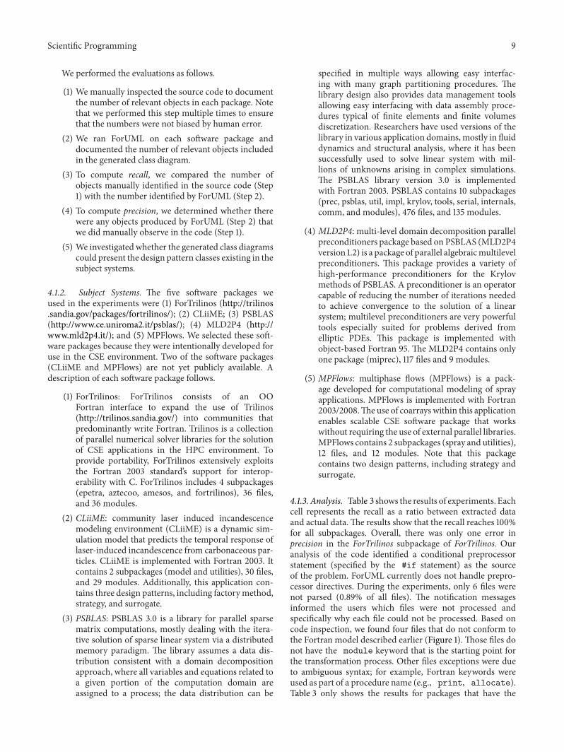
ForUML. Figure 5 illustrates how a user can select multipleFortran source files for input to ForUML. The Add buttonopens a new window to select target file(s). Users can removethe selected file(s) by selecting the Remove button. The Resetbutton clears all selected files. After selecting the sourcefiles, the user chooses the location to save the generatedXMI document (.xmi file). The Generate button activatesthe transformation process. During the process, the usercan see whether each given source file is successfully parsedor not (Figure 6). Once the XMI document is successfullygenerated, the user can view the class diagram by selectingthe View button. Figure 7 illustrates the UML class diagramthat is automatically represented in the editing pane withthe ArgoUML. ArgoUML allows users to refine the diagramand then decide to either save the project or export the XMIdocument, which contains all the modified information.
4. Evaluation
To assess the effectiveness of ForUML, we conducted somesmall experiments to gather data about its accuracy inextracting UML constructs from code. This section also
Figure 6: Generating the XMI.
Figure 7: Viewing the UML class diagram.
provides some lessons learned from the studies and feedbackfrom the SEC-HPC’13 workshop audience.
4.1. Controlled Experiment. The following subsections pro-vide the details of a controlled experiment to evaluateForUML. The accompanying website (http://aziz.students.cs.ua.edu/foruml-eval.htm) contains all of the class diagrams.The website also provides the ForUML executable (sourcecode is not available yet) for download.
4.1.1. Experimental Design. We evaluated the accuracy ofForUML on five OO Fortran software packages by adoptingthe definitions of recall and precision defined by Tonella andPotrich [49].
(i) Recallmeasures the percentage of the various objects,that is, type, components, type-bound procedure, andassociations, in the source code correctly identified byForUML.
(ii) Precisionmeasures the percentage of the objects iden-tified by ForUML that are correct when comparedwith the source code.
Scientific Programming 9
We performed the evaluations as follows.
(1) We manually inspected the source code to documentthe number of relevant objects in each package. Notethat we performed this step multiple times to ensurethat the numbers were not biased by human error.
(2) We ran ForUML on each software package anddocumented the number of relevant objects includedin the generated class diagram.
(3) To compute recall, we compared the number ofobjects manually identified in the source code (Step1) with the number identified by ForUML (Step 2).
(4) To compute precision, we determined whether therewere any objects produced by ForUML (Step 2) thatwe did manually observe in the code (Step 1).
(5) We investigated whether the generated class diagramscould present the design pattern classes existing in thesubject systems.
4.1.2. Subject Systems. The five software packages weused in the experiments were (1) ForTrilinos (http://trilinos.sandia.gov/packages/fortrilinos/); (2) CLiiME; (3) PSBLAS(http://www.ce.uniroma2.it/psblas/); (4) MLD2P4 (http://www.mld2p4.it/); and (5) MPFlows. We selected these soft-ware packages because they were intentionally developed foruse in the CSE environment. Two of the software packages(CLiiME and MPFlows) are not yet publicly available. Adescription of each software package follows.
(1) ForTrilinos: ForTrilinos consists of an OOFortran interface to expand the use of Trilinos(http://trilinos.sandia.gov/) into communities thatpredominantly write Fortran. Trilinos is a collectionof parallel numerical solver libraries for the solutionof CSE applications in the HPC environment. Toprovide portability, ForTrilinos extensively exploitsthe Fortran 2003 standard’s support for interop-erability with C. ForTrilinos includes 4 subpackages(epetra, aztecoo, amesos, and fortrilinos), 36 files,and 36 modules.
(2) CLiiME: community laser induced incandescencemodeling environment (CLiiME) is a dynamic sim-ulation model that predicts the temporal response oflaser-induced incandescence from carbonaceous par-ticles. CLiiME is implemented with Fortran 2003. Itcontains 2 subpackages (model and utilities), 30 files,and 29 modules. Additionally, this application con-tains three design patterns, including factorymethod,strategy, and surrogate.
(3) PSBLAS: PSBLAS 3.0 is a library for parallel sparsematrix computations, mostly dealing with the itera-tive solution of sparse linear system via a distributedmemory paradigm. The library assumes a data dis-tribution consistent with a domain decompositionapproach, where all variables and equations related toa given portion of the computation domain areassigned to a process; the data distribution can be
specified in multiple ways allowing easy interfac-ing with many graph partitioning procedures. Thelibrary design also provides data management toolsallowing easy interfacing with data assembly proce-dures typical of finite elements and finite volumesdiscretization. Researchers have used versions of thelibrary in various application domains,mostly in fluiddynamics and structural analysis, where it has beensuccessfully used to solve linear system with mil-lions of unknowns arising in complex simulations.The PSBLAS library version 3.0 is implementedwith Fortran 2003. PSBLAS contains 10 subpackages(prec, psblas, util, impl, krylov, tools, serial, internals,comm, and modules), 476 files, and 135 modules.
(4) MLD2P4: multi-level domain decomposition parallelpreconditioners package based on PSBLAS (MLD2P4version 1.2) is a package of parallel algebraicmultilevelpreconditioners. This package provides a variety ofhigh-performance preconditioners for the Krylovmethods of PSBLAS. A preconditioner is an operatorcapable of reducing the number of iterations neededto achieve convergence to the solution of a linearsystem; multilevel preconditioners are very powerfultools especially suited for problems derived fromelliptic PDEs. This package is implemented withobject-based Fortran 95. The MLD2P4 contains onlyone package (miprec), 117 files and 9 modules.
(5) MPFlows: multiphase flows (MPFlows) is a pack-age developed for computational modeling of sprayapplications. MPFlows is implemented with Fortran2003/2008.The use of coarrays within this applicationenables scalable CSE software package that workswithout requiring the use of external parallel libraries.MPFlows contains 2 subpackages (spray and utilities),12 files, and 12 modules. Note that this packagecontains two design patterns, including strategy andsurrogate.
4.1.3. Analysis. Table 3 shows the results of experiments. Eachcell represents the recall as a ratio between extracted dataand actual data.The results show that the recall reaches 100%for all subpackages. Overall, there was only one error inprecision in the ForTrilinos subpackage of ForTrilinos. Ouranalysis of the code identified a conditional preprocessorstatement (specified by the #if statement) as the sourceof the problem. ForUML currently does not handle prepro-cessor directives. During the experiments, only 6 files werenot parsed (0.89% of all files). The notification messagesinformed the users which files were not processed andspecifically why each file could not be processed. Based oncode inspection, we found four files that do not conform tothe Fortran model described earlier (Figure 1). Those files donot have the module keyword that is the starting point forthe transformation process. Other files exceptions were dueto ambiguous syntax; for example, Fortran keywords wereused as part of a procedure name (e.g., print, allocate).Table 3 only shows the results for packages that have the
10 Scientific Programming
Table 3: Evaluation of ForUML: recall (extracted data/actual data).
Packages Subpackages Type Procedure Component Inheritance Composition
ForTrilinos
Epetra 16/16 304/304 17/17 12/12 2/2Aztecoo 1/1 12/12 1/1 0/0 0/0Amesos 1/1 7/7 1/1 0/0 0/0
ForTrilinos 48/48 11/11 139/139 4/4 4/4CLiiME Model 23/23 167/167 61/61 32/32 32/32
PSBLAS Modules 50/50 1309/1309 160/160 34/34 28/28prec 20/20 208/208 28/28 24/24 12/12
MLDP4 miprec 11/11 0/0 67/66 0/0 10/10MPFlows Spray 10/10 55/55 29/29 2/2 3/3
Overall 180/180 2073/2073 503/503 108/108 91/91(100%) (100%) (100%) (100%) (100%)
time advance(dt : real)set quadrature(inout this : integrand,s : strategy)get quadrature(model : integrand)t(inout dState dt : integrand)add(operator result : integrand)multiply(lhs : integrand,operator result : real)
time advance(inout this : surrogate,dt : real)
runge kutta 4th
time advance(inout this : surrogate,this temp : real)
≪Coarray≫ index cell : integer▯≪Coarray≫ p last : integer▯
≪Overloading of new particles≫ allocate particles(inout this : particles)locate particles(inout this : particles)all images relocate particles(inout this : particles)
assign(inout lhs : particles,rhs : local particles)add(this : particles,add particles : local particles)multiple(this : particles,multiple particles : real)
integrandquadrature : strategy
surrogate
strategy
particles
time : real
interpolate(inout this : particles)
assign(rhs : integrand,inout lhs : integrand)
≪Coarray≫ p : real▯
Figure 8: The class diagram (partial): MPFlows.
type construct.We only evaluated the correctness of ForUMLcurrent capabilities.
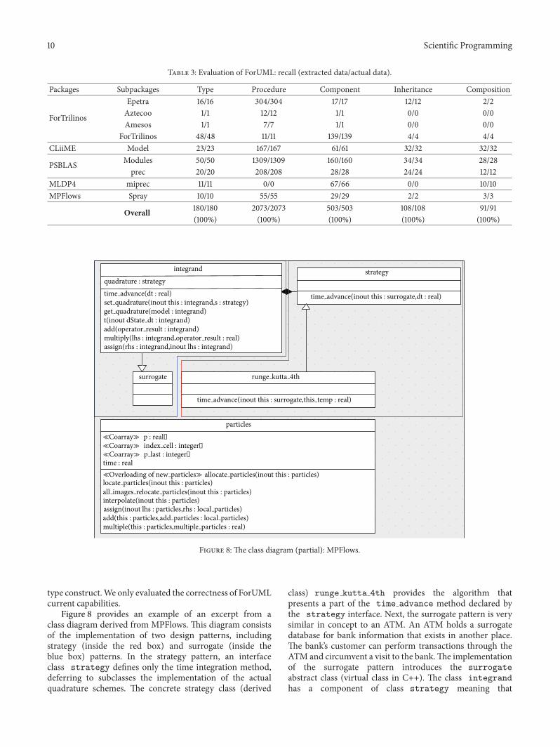
Figure 8 provides an example of an excerpt from aclass diagram derived from MPFlows. This diagram consistsof the implementation of two design patterns, includingstrategy (inside the red box) and surrogate (inside theblue box) patterns. In the strategy pattern, an interfaceclass strategy defines only the time integration method,deferring to subclasses the implementation of the actualquadrature schemes. The concrete strategy class (derived
class) runge kutta 4th provides the algorithm thatpresents a part of the time advance method declared bythe strategy interface. Next, the surrogate pattern is verysimilar in concept to an ATM. An ATM holds a surrogatedatabase for bank information that exists in another place.The bank’s customer can perform transactions through theATM and circumvent a visit to the bank.The implementationof the surrogate pattern introduces the surrogateabstract class (virtual class in C++). The class integrandhas a component of class strategy meaning that
Scientific Programming 11
Factory Method
conductionEnergyscatteringEnergy
absorptionEnergy
annealingEnergy
object
stamped : logical
Surrogate
Surrogate integrand
quadrature : strategy
Strategy strategy
ienergy
coatingEnergy
extinctionEnergy
sublimationexEnergy
radiationEnergy
sublimationEnergyoxidationEnergy
thermionicEnergy
particle
energy : energyModels
OxidationEnergy(inout this : particle)
SublimationEnergy(inout this : particle)
AbsorptionEnergy(inout this : particle)
ConductionEnergy(inout this : particle)
AnnealingEnergy(inout this : particle)
RadiationEnergy(inout this : particle)
ScatteringEnergy(inout this : particle)
ThermionicEnergy(inout this : particle]
ExtinctionEnergy(inout this : particle)
CoatingEnergy(inout this : particle)
SublimationexEnergy(inout this : particle]
DmOxidation(inout this : particle)
DmSublimation(inout this : particle)
DmSublimationex(inout this : particle)
assign(inout lhs: particle,rhs : integrand)
Temperature(this : particle)
time(this : particle)
Energy(inout this : conductionEnergy,properties : physical properties,laser : laser properties)
≪Constructor≫ conductionEnergy(filename : character)
≪Constructor≫ absorptionEnergy(filename : character)
Energy(inout this : annealingEnergy,properties : physical properties,laser: laser properties)
Dmdt(inout this : annealingEnergy,properties : physical properties,laser : laser properties)
Dmd(inout this : coatingEnergy,properties : physical properties,laser : laser properties)
≪Constructor≫ coatingEnergy(filename : character)
Energy(inout this : extinctionEnergy,properties : physical properties,laser : laser properties)
Dmdt(inout this : extinctionEnergy,properties : physical properties,laser : laser properties)
≪Constructor≫ extinctionEnergy(filename : character)
Energ(inout this : sublimationexEnergy,properties : physical properties,laser : laser properties)
Dmdt(inout this : sublimationexEnergy,properties : physical properties,laser : laser properties)
≪Constructor≫ sublimationexEnergy(filename : character)
Energ(inout this : scatteringEnergy,properties : physical properties,laser : laser properties)
Dmdt(inout this : scatteringEnergy,properties : physical properties,laser : laser properties)
≪Constructor≫ scatteringEnergy(filename : character)
Energ(inout this : ienergy,properties : physical properties,laser : laser properties)
Dmdt(inout this : ienergy,properties : physical properties,laser : laser properties)
dm : real
Energ(inout this : sublimationEnergy,properties : physical properties,laser : laser properties)
Dmdt(inout this : sublimationEnergy,properties : physical properties,laser : laser properties)
≪Constructor≫ sublimationEnergy(filename : character)
Energ(inout this : thermionicEnergy,properties : physical properties,laser : laser properties)
Dmdt(inout this : thermionicEnergy,properties : physical properties,laser : laser properties)
≪Constructor≫ thermionicEnergy(filename : character)
Set quadrature(inout this : integrand,s : strategy
Get quadrature(model : integrand)
t(inout dState dt : integrand)
add(operator result : integrand)
multiply(lhs : integrand,operator result : real)
assign(rhs : integrand,inout lhs : integrand)
runge kutta 4thrunge kutta 2nd
Energ(inout this : radiationEnergy,properties : physical properties,laser : laser properties)
Dmdt(inout this : radiationEnergy,properties : physical properties,laser : laser properties)
≪Constructor≫ radiationEnergy(filename : character)
Energ(inout this : oxidationEnergy,properties : physical properties,laser : laser properties)
Dmdt(inout this : oxidationEnergy,properties : physical properties,laser : laser properties)
≪Constructor≫ oxidationEnergy(filename : character)
properties : physical properties
laser : laser properties
t(inout local d dt : particle)
add(lhs : particle,local sum : integrand)
Diameter(this : particle)
Dcoat(this : particle)
output state(inout this : particle,suffix : character)
Dmdt(inout this : conductionEnergy,properties : physical properties,laser : laser properties)
Dmdt(inout this : absorptionEnergy,properties : physical properties,laser : laser properties)
Energ(inout this : absorptionEnergy,properties : physical properties,laser : laser properties)
≪Constructor≫ annealingEnergy()
time advance(inout this : surrogate,this half : real)time advance(inout this : surrogate,this temp : real)
time advance(inout this : surrogate,dt : real)
Energ(inout this : coatingEnergy,properties : physical properties,laser : laser properties)
time advanced(dt : real)
Figure 9: The class diagram (partial): CLiiME.
the surrogate allows us to pass an integrand childclass dummy argument to the type-bound proceduresimplemented in runge kutta 4th. The class particlecontains components and type-bound procedures computingthe energy of the particle. In Fortran, each dummy argumenthas three possible intent attributes including IN, OUT,and INOUT. Therefore, each parameter, which is passed tothe operation in the diagram, needs to be specified witha specific intent. In the class diagram, the keyword IN isomitted because ArgoUML assumes that a parameter has theIN by default.
4.2. Experience. The following subsections describe ourexperiences using ForUML on a real CSE project and discussfeedback on ForUML we received during the SE-HPCCSE’13workshop.
4.2.1. CLiiME Project. ForUML played a significant role inthe development of the CLiiME package [50].The developersused ForUML to validate the design after each code refac-toring process. The developers compared the class diagram
produced by ForUMLwith the originally agreed upon design.After comparison, they determined instances in which thecode implementation deviated from the design. Instead ofinspecting the source code manually, the developers wereable to make the comparison/decision with less effort. Also,the developers were able to use the extracted UML diagramsto identify code smells, places where the code might inducesome defects in the future. For instance, we inspected theUML class diagrams and identified places where classeshad too many type-bound procedure or procedures withtoo many arguments, all of which we corrected during therefactoring process.
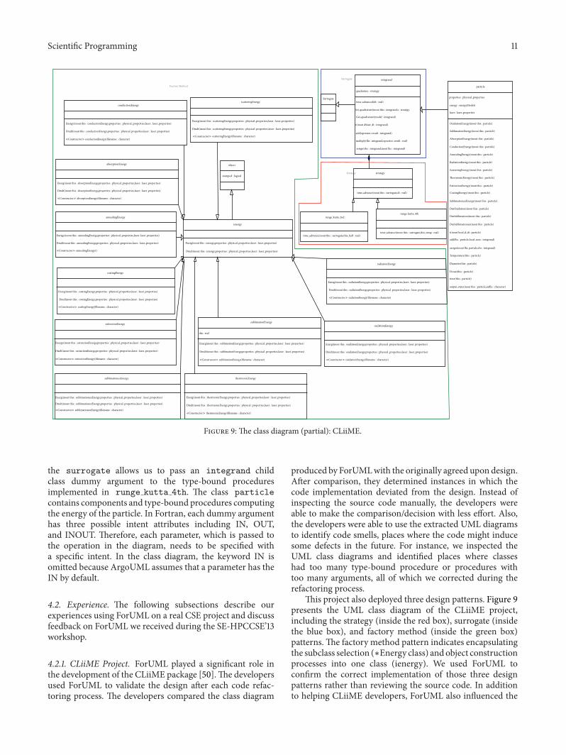
This project also deployed three design patterns. Figure 9presents the UML class diagram of the CLiiME project,including the strategy (inside the red box), surrogate (insidethe blue box), and factory method (inside the green box)patterns.The factory method pattern indicates encapsulatingthe subclass selection (∗Energy class) andobject constructionprocesses into one class (ienergy). We used ForUML toconfirm the correct implementation of those three designpatterns rather than reviewing the source code. In additionto helping CLiiME developers, ForUML also influenced the
12 Scientific Programming
Figure 10: Example of larger classes.
development of PSBLAS version 3.1, by allowing a compre-hensive and unitary view of the project.
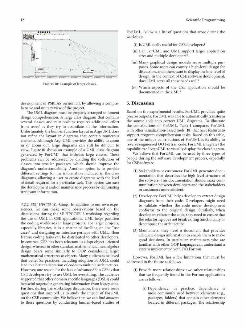
The UML diagram must be properly arranged to fomentdesign comprehension. A large class diagram that containsseveral classes and relationships requires additional effortfrom users’ as they try to assimilate all the information.Unfortunately, the built-in function layout in ArgoUML doesnot refine the layout in diagrams that contain numerouselements. Although ArgoUML provides the ability to zoomin or zoom out, large diagrams can still be difficult toview. Figure 10 shows an example of a UML class diagramgenerated by ForUML that includes large classes. Theseproblems can be addressed by dividing the collection ofclasses into smaller packages, which should improve thediagram’s understandability. Another option is to providedifferent settings for the information included in the classdiagrams, allowing a user to create diagrams with the levelof detail required for a particular task. This option can easethe development and/or maintenance process by eliminatingirrelevant information.
4.2.2. SEC-HPC’13 Workshop. In addition to our own expe-riences, we can make some observations based on thediscussions during the SE-HPCCSE’13 workshop regardingthe use of UML in CSE applications. UML helps partitionthe coding workloads in large projects. For larger projects,especially libraries, it is a matter of dwelling on the “usecases” and designing an interface perhaps with UML. Thenfeature coding tasks can be distributed to other developers.In contrast, CSE has been reluctant to adopt object-orienteddesign,whereas in other standardmathematics, linear algebradesign bears some similarly to OOP considering largermathematical structures as objects. Many audiences believedthat better SE practices, including adoption ForUML couldlead to a better adaptation of codes to multiple architectures.However, one reason for the lack of advance SE in CSE is thatCSE developers try to use UML for everything. The audiencesuggested that other domain specific languages (DSLs) couldbe useful targets for generating information from legacy code.Further, during the workshop’s discussion, there were somequestions that inspired us to study the impact of ForUMLon the CSE community. We believe that we can find answersto these questions by conducting human-based studies of
ForUML. Below is a list of questions that arose during theworkshop.
(i) Is UML really useful for CSE developers?(ii) Can ForUML and UML support larger application
sizes and multiple developers?(iii) Many graphical design models serve multiple pur-
poses. Some users can convey a high-level design fordiscussion, and others want to display the low-level ofdesign. In the context of CSE software development,does UML serve all these needs well?
(iv) Which aspects of the CSE application should bedocumented in the UML?
5. Discussion
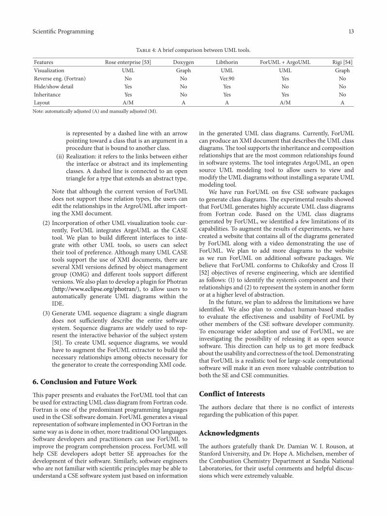
Based on the experimental results, ForUML provided quiteprecise outputs. ForUMLwas able to automatically transformthe source code into correct UML diagrams. To illustratethe contributions of ForUML, Table 4 compares ForUMLwith other visualization-based tools [18] that have features tosupport program comprehension tasks. Based on this table,one of the unique contributions of ForUML is its ability toreverse engineered OO Fortran code. ForUML integrates thecapabilities of ArgoUML to visually display the class diagram.
We believe that ForUML can be used by three types ofpeople during the software development process, especiallyfor CSE software.
(1) Stakeholders or customers: ForUML generates docu-mentation that describes the high-level structure ofthe software. This documentation should make com-munication between developers and the stakeholdersor customers more efficient.
(2) Developers: ForUML helps developers extract designdiagrams from their code. Developers might needto validate whether the code under developmentconforms to the original design. Similarly, whendevelopers refactor the code, they need to ensure thatthe refactoring does not break exiting functionality ordecompose the architecture.
(3) Maintainers: they need a document that providesadequate design information to enable them to makegood decisions. In particular, maintainers who arefamiliar with other OOP languages can understand asystem implemented with OO Fortran.
However, ForUML has a few limitations that must beaddressed in the future as follows.
(1) Provide more relationships: two other relationshipsthat we frequently found in the Fortran applicationsare as follows.
(i) Dependency: in practice, dependency ismost commonly used between elements (e.g.,packages, folders) that contain other elementslocated in different packages. The relationship
Scientific Programming 13
Table 4: A brief comparison between UML tools.
Features Rose enterprise [53] Doxygen Libthorin ForUML + ArgoUML Rigi [54]Visualization UML Graph UML UML GraphReverse eng. (Fortran) No No Ver.90 Yes NoHide/show detail Yes No Yes No NoInheritance Yes No Yes Yes NoLayout A/M A A A/M ANote: automatically adjusted (A) and manually adjusted (M).
is represented by a dashed line with an arrowpointing toward a class that is an argument in aprocedure that is bound to another class.
(ii) Realization: it refers to the links between eitherthe interface or abstract and its implementingclasses. A dashed line is connected to an opentriangle for a type that extends an abstract type.
Note that although the current version of ForUMLdoes not support these relation types, the users canedit the relationships in the ArgroUML after import-ing the XMI document.
(2) Incorporation of other UML visualization tools: cur-rently, ForUML integrates ArgoUML as the CASEtool. We plan to build different interfaces to inte-grate with other UML tools, so users can selecttheir tool of preference. Although many UML CASEtools support the use of XMI documents, there areseveral XMI versions defined by object managementgroup (OMG) and different tools support differentversions.We also plan to develop a plugin for Photran(http://www.eclipse.org/photran/), to allow users toautomatically generate UML diagrams within theIDE.
(3) Generate UML sequence diagram: a single diagramdoes not sufficiently describe the entire softwaresystem. Sequence diagrams are widely used to rep-resent the interactive behavior of the subject system[51]. To create UML sequence diagrams, we wouldhave to augment the ForUML extractor to build thenecessary relationships among objects necessary forthe generator to create the corresponding XMI code.
6. Conclusion and Future Work
This paper presents and evaluates the ForUML tool that canbe used for extracting UML class diagram from Fortran code.Fortran is one of the predominant programming languagesused in the CSE software domain. ForUML generates a visualrepresentation of software implemented inOO Fortran in thesame way as is done in other, more traditional OO languages.Software developers and practitioners can use ForUML toimprove the program comprehension process. ForUML willhelp CSE developers adopt better SE approaches for thedevelopment of their software. Similarly, software engineerswho are not familiar with scientific principles may be able tounderstand a CSE software system just based on information
in the generated UML class diagrams. Currently, ForUMLcan produce an XMI document that describes the UML classdiagrams.The tool supports the inheritance and compositionrelationships that are the most common relationships foundin software systems. The tool integrates ArgoUML, an opensource UML modeling tool to allow users to view andmodify the UML diagramswithout installing a separate UMLmodeling tool.
We have run ForUML on five CSE software packagesto generate class diagrams. The experimental results showedthat ForUML generates highly accurate UML class diagramsfrom Fortran code. Based on the UML class diagramsgenerated by ForUML, we identified a few limitations of itscapabilities. To augment the results of experiments, we havecreated a website that contains all of the diagrams generatedby ForUML along with a video demonstrating the use ofForUML. We plan to add more diagrams to the websiteas we run ForUML on additional software packages. Webelieve that ForUML conforms to Chikofsky and Cross II[52] objectives of reverse engineering, which are identifiedas follows: (1) to identify the system’s component and theirrelationships and (2) to represent the system in another formor at a higher level of abstraction.
In the future, we plan to address the limitations we haveidentified. We also plan to conduct human-based studiesto evaluate the effectiveness and usability of ForUML byother members of the CSE software developer community.To encourage wider adoption and use of ForUML, we areinvestigating the possibility of releasing it as open sourcesoftware. This direction can help us to get more feedbackabout the usability and correctness of the tool. Demonstratingthat ForUML is a realistic tool for large-scale computationalsoftware will make it an even more valuable contribution toboth the SE and CSE communities.
Conflict of Interests
The authors declare that there is no conflict of interestsregarding the publication of this paper.
Acknowledgments
The authors gratefully thank Dr. Damian W. I. Rouson, atStanford University, and Dr. Hope A. Michelsen, member ofthe Combustion Chemistry Department at Sandia NationalLaboratories, for their useful comments and helpful discus-sions which were extremely valuable.
14 Scientific Programming
References
[1] National Science Foundation, Cyberinfrastructure for 21stCentury Science and Engineering Advanced Computing Infra-structure (Vision and Strategies Plan), 2012, http://www.nsf.gov/pubs/2012/nsf12051/nsf12051.pdf.
[2] J. C. Carver, “Software engineering for computational scienceand engineering,”Computing in Science and Engineering, vol. 14,no. 2, Article ID 6159198, pp. 8–11, 2011.
[3] J. H. Marburget, “Report of the high-end computing revital-ization task force (hecrtf),” Tech. Rep., National CoordinationOffice for Information Technology Research and Development,2004.
[4] V. K. Decyk, C. D. Norton, and H. J. Gardner, “Why fortran?”Computing in Science and Engineering, vol. 9, no. 4, Article ID4263269, pp. 68–71, 2007.
[5] E. Akin,Object-Oriented Programming via Fortran 90/95, Cam-bridge University Press, Cambridge, UK, 2003.
[6] V. K. Decyk, C. D. Norton, and B. K. Szymanski, “Expressingobject-oriented concepts in Fortran 90,” ACM SIGPLAN For-tran Forum, vol. 16, no. 1, pp. 13–18, 1997.
[7] V. K. Decyk, C. D. Norton, and B. K. Szymanski, “How tosupport inheritance and run-time polymorphism in Fortran90,” Computer Physics Communications, vol. 115, no. 1, pp. 9–17,1998.
[8] D. Barbieri, V. Cardellini, S. Filippone, and D. Rouson, “Designpatterns for scientific computations on sparse matrices,” inProceedings of the International Conference on Parallel Processing(Euro-Par ’11), vol. 7155 of LectureNotes in Computer Science, pp.367–376, Springer, Berlin, Germany, 2012.
[9] S. Filippone and A. Buttari, “Object-oriented techniques forsparse matrix computations in Fortran 2003,” ACM Transac-tions on Mathematical Software, vol. 38, no. 4, article 23, 2012.
[10] K. Morris, D. W. I. Rouson, M. N. Lemaster, and S. Filippone,“Exploring capabilities within ForTrilinos by solving the 3DBurgers equation,” Scientific Programming, vol. 20, no. 3, pp.275–292, 2012.
[11] D. W. Rouson, J. Xia, and X. Xu, “Object construction anddestruction design patterns in fortran 2003,” Procedia ComputerScience, vol. 1, no. 1, pp. 1495–1504, 2003.
[12] D. W. I. Rouson, H. Adalsteinsson, and J. Xia, “Design patternsfor multiphysics modeling in Fortran 2003 and C++,” ACMTransactions on Mathematical Software, vol. 37, no. 1, article 3,2010.
[13] Z.Merali, “Computational science: ...Error,”Nature, vol. 467, no.7317, pp. 775–777, 2010.
[14] A. Nanthaamornphong, K. Morris, and S. Filippone, “Extract-ing uml class diagrams from object-oriented fortran: Foruml,”in Proceedings of the 1st International Workshop on SoftwareEngineering for High Performance Computing in ComputationalScience and Engineering (SE-HPCCSE ’13), pp. 9–16, Denver,Colo, USA, November 2013.
[15] J. C. Carver, “Report: the second international workshop onsoftware engineering for CSE,” Computing in Science andEngineering, vol. 11, no. 6, Article ID 5337640, pp. 14–19, 2009.
[16] G. V. Wilson, “What should computer scientists teach tophysical scientists and engineers?” IEEE Computational Science& Engineering, vol. 3, no. 2, pp. 46–55, 1996.
[17] J. C. Carver, R. P. Kendall, S. E. Squires, and D. E. Post, “Soft-ware development environments for scientific and engineeringsoftware: a series of case studies,” in Proceedings of the 29th
International Conference on Software Engineering (ICSE ’07), pp.550–559, Minneapolis, Minn, USA, May 2007.
[18] M.-A. Storey, “Theories, tools and researchmethods in programcomprehension: past, present and future,” Software QualityJournal, vol. 14, no. 3, pp. 187–208, 2006.
[19] M. J. Pacione, “Software visualisation for object-oriented pro-gram comprehension,” in Proceedings of the 26th InternationalConference on Software Engineering (ICSE ’04), pp. 63–65, May2004.
[20] J. Segal, “Professional end user developers and software devel-opment knowledge,” Tech. Rep., OpenUniversity, England, UK,2004.
[21] M. T. Sletholt, J. E. Hannay, D. Pfahl, and H. P. Langtangen,“What dowe know about scientific software development’s agilepractices?” Computing in Science and Engineering, vol. 14, no. 2,Article ID 6081842, pp. 24–36, 2012.
[22] R. N. Britcher, “Re-engineering software: a case study,” IBMSystems Journal, vol. 29, no. 4, pp. 551–567, 1990.
[23] I. Jacobson, G. Booch, and J. Rumbaugh, The Unified SoftwareDevelopment Process, AddisonWesley Longman, Boston, Mass,USA, 1999.
[24] T. C. Lethbridge, S. Tichelaar, and E. Ploedereder, “The dagstuhlmiddle metamodel: a schema for reverse engineering,” Elec-tronic Notes in Theoretical Computer Science, vol. 94, pp. 7–18,2004.
[25] OMG, OMG Model Driven Architecture (MDA), 1997,http://www.omg.org/mda/.
[26] Object Management Group (OMG), 1997, http://www.omg.org.[27] M. H. Alalfi, J. R. Cordy, and T. R. Dean, “Automated reverse
engineering of UML sequence diagrams for dynamic web appli-cations,” in Proceedings of the IEEE International Conferenceon Software Testing, Verification, and Validation Workshops(ICSTW ’09), pp. 287–294, Denver, Colo, USA, April 2009.
[28] M. H. Alalfi, J. R. Cordy, and T. R. Dean, “SQL2XMI: reverseengineering of UML-ER diagrams from relational databaseschemas,” in Proceedings of the 15th Working Conference onReverse Engineering (WCRE ’08), pp. 187–191, Antwerp, Bel-gium, October 2008.
[29] E. Korshunova, M. Petkovic, M. van den Brand, and M.Mousavi, “CPP2XMI: reverse engineering of UML class,sequence, and activity diagrams fromC++ source code,” in Pro-ceedings of the 13th Working Conference on Reverse Engineering(WCRE ’06), pp. 297–298, Benevento, Italy, October 2006.
[30] E. Gansner, E. Koutsofios, S. North, and K.-P. Vo, “A techniquefor drawing directed graphs,” IEEE Transactions on SoftwareEngineering, vol. 19, no. 3, pp. 214–230, 1993.
[31] E. B. Duffy and B. A. Malloy, “A language and platform-independent approach for reverse engineering,” in Proceedingsof the 3rd ACIS International Conference on Software Engineer-ing Research,Management andApplications (SERA ’05), pp. 415–422, Pleasant, Mich, USA, August 2005.
[32] V. K. Decyk, C. D. Norton, and B. K. Szymanski, “How toexpress C++ concepts in Fortran 90,” Scientific Programming,vol. 6, no. 4, pp. 363–390, 1997.
[33] W. S. Brainerd, Guide to Fortran 2003 Programming, Springer,1st edition, 2009.
[34] M. Metcalf, J. Reid, and M. Cohen, Modern Fortran Explained,Oxford University Press, New York, NY, USA, 4th edition, 2011.
[35] D. Rouson, J. Xia, and X. Xu, Scientific Software Design: TheObject-Oriented Way, Cambridge University Press, New York,NY, USA, 1st edition, 2011.
Scientific Programming 15
[36] I. D. Chivers and J. Sleightholme, “Compiler support for theFortran 2003 and 2008 Standards Revision 11,” ACM SIGPLANFortran Forum, vol. 31, no. 3, pp. 17–28, 2012.
[37] J. Reid, “Coarrays in the next fortran standard,” SIGPLANFortran Forum, vol. 29, no. 2, pp. 10–27, 2010.
[38] E. Gamma, R. Helm, R. Johnson, and J. Vlissides, Design Pat-terns: Elements of Reusable Object-Oriented Software, Addison-Wesley, Longman Publishing, Boston, Mass, USA, 1995.
[39] T. Mattson, B. Sanders, and B. Massingill, Patterns for ParallelProgramming, Addison-Wesley Professional, 1st edition, 2004.
[40] J. L. Ortega-Arjona, Patterns for Parallel Software Design, JohnWiley & Sons, 1st edition, 2010.
[41] M. Weidmann, “Design and performance improvement of areal-world, object-oriented C++ solver with STL,” in Scien-tific Computing in Object-Oriented Parallel Environments, Y.Ishikawa, R. Oldehoeft, J. Reynders, andM.Tholburn, Eds., vol.1343 of Lecture Notes in Computer Science, pp. 25–32, Springer,Berlin, Germany, 1997.
[42] A. Markus, “Design patterns and Fortran 90/95,” ACM SIG-PLAN Fortran Forum, vol. 25, no. 1, pp. 13–29, 2006.
[43] A.Markus, “Design patterns and Fortran 2003,”ACMSIGPLANFortran Forum, vol. 27, no. 3, pp. 2–15, 2008.
[44] H. Neunzert, A. Klar, and J. Struckmeier, “Particle methods:theory and applications,” Tech. Rep. 95-113, Fachbereich Math-ematik, Universitat Kaiserslautern, Kaiserslautern, Germany,1995.
[45] V. K. Decyk andH. J. Gardner, “Object-oriented design patternsin Fortran 90/95: mazev1, mazev2 and mazev3,” ComputerPhysics Communications, vol. 178, no. 8, pp. 611–620, 2008.
[46] H. A.Muller, J. H. Jahnke, D. B. Smith, M.-A. Storey, S. R. Tilley,and K.Wong, “Reverse engineering: a roadmap,” in Proceedingsof the Conference onThe Future of Software Engineering, pp. 47–60, Limerick, Ireland, June 2000.
[47] M. Fowler, Refactoring: Improving the Design of Existing Code,Addison-Wesley Longman, Boston, Mass, USA, 1999.
[48] T. J. Parr and R. W. Quong, “ANTLR: a predicated-LL(k) parsergenerator,” Software: Practice and Experience, vol. 25, no. 7, pp.789–810, 1995.
[49] P. Tonella and A. Potrich, “Reverse engineering of the UMLclass diagram from C++ code in presence of weakly typedcontainers,” in Proceedings of the IEEE International Conferenceon Software Maintenance (ICSM ’01), pp. 376–385, Florence,Italy, November 2001.
[50] A. Nanthaamornphong, K. Morris, D. W. I. Rouson, and H.A. Michelsen, “A case study: agile development in the com-munity laser-induced incandescence modeling environment(CLiiME),” in Proceedings of the 5th International Workshop onSoftware Engineering for Computational Science and Engineer-ing, pp. 9–18, San Francisco, Calif, USA, May 2013.
[51] L. C. Briand, Y. Labiche, and Y. Miao, “Towards the reverseengineering of UML sequence diagrams,” in Proceedings of the10th Working Conference on Reverse Engineering, pp. 57–66,Victoria, Canada, November 2003.
[52] E. J. Chikofsky and J. H. Cross II, “Reverse engineering anddesign recovery: a taxonomy,” IEEE Software, vol. 7, no. 1, pp.13–17, 1990.
[53] IBM, Rational Rose Enterprise, 2013, http://www-03.ibm.com/software/products/en/enterprise/.
[54] Department of Computer Science University of Victoria, Rigi,2001, http://www.rigi.cs.uvic.ca/rigi/blurb/rigi-blurb.html.

Submit your manuscripts athttp://www.hindawi.com
Computer Games Technology
International Journal of
Hindawi Publishing Corporationhttp://www.hindawi.com Volume 2014
Hindawi Publishing Corporationhttp://www.hindawi.com Volume 2014
Distributed Sensor Networks
International Journal of
Advances in
FuzzySystems
Hindawi Publishing Corporationhttp://www.hindawi.com
Volume 2014
International Journal of
ReconfigurableComputing
Hindawi Publishing Corporation http://www.hindawi.com Volume 2014
Hindawi Publishing Corporationhttp://www.hindawi.com Volume 2014
Applied Computational Intelligence and Soft Computing
Advances in
Artificial Intelligence
Hindawi Publishing Corporationhttp://www.hindawi.com Volume 2014
Advances inSoftware EngineeringHindawi Publishing Corporationhttp://www.hindawi.com Volume 2014
Hindawi Publishing Corporationhttp://www.hindawi.com Volume 2014
Electrical and Computer Engineering
Journal of
Journal of
Computer Networks and Communications
Hindawi Publishing Corporationhttp://www.hindawi.com Volume 2014
Hindawi Publishing Corporation
http://www.hindawi.com Volume 2014
Advances in
Multimedia
International Journal of
Biomedical Imaging
Hindawi Publishing Corporationhttp://www.hindawi.com Volume 2014
ArtificialNeural Systems
Advances in
Hindawi Publishing Corporationhttp://www.hindawi.com Volume 2014
RoboticsJournal of
Hindawi Publishing Corporationhttp://www.hindawi.com Volume 2014
Hindawi Publishing Corporationhttp://www.hindawi.com Volume 2014
Computational Intelligence and Neuroscience
Industrial EngineeringJournal of
Hindawi Publishing Corporationhttp://www.hindawi.com Volume 2014
Modelling & Simulation in EngineeringHindawi Publishing Corporation http://www.hindawi.com Volume 2014
The Scientific World JournalHindawi Publishing Corporation http://www.hindawi.com Volume 2014
Hindawi Publishing Corporationhttp://www.hindawi.com Volume 2014
Human-ComputerInteraction
Advances in
Computer EngineeringAdvances in
Hindawi Publishing Corporationhttp://www.hindawi.com Volume 2014