Embed Size (px)
Citation preview
Research ArticleVibration Control of Nuclear Power Plant Piping System UsingStockbridge Damper under Earthquakes
Seongkyu Chang1 Weipeng Sun2 Sung Gook Cho3 and Dookie Kim4
1Academic-Industry Cooperation Foundation Kunsan National University Jeonbuk Republic of Korea2Department of Mechanics and Engineering Science School of Mathematics Jilin University Changchun 130012 China3RampD Center Innose Tech Co Ltd Incheon 406-840 Republic of Korea4Department of Civil Engineering Kunsan National University Jeonbuk Republic of Korea
Correspondence should be addressed to Seongkyu Chang s9752033gmailcom
Received 6 September 2016 Accepted 3 November 2016
Academic Editor Eugenijus Uspuras
Copyright copy 2016 Seongkyu Chang et al This is an open access article distributed under the Creative Commons AttributionLicense which permits unrestricted use distribution and reproduction in any medium provided the original work is properlycited
Generally the piping system of a nuclear power plant (NPP) has to be designed for normal loads such as dead weight internalpressure temperature and accidental loads such as earthquake In the proposed paper effect of Stockbridge damper to mitigatethe response of piping system of NPP subjected to earthquake is studied Finite element analysis of piping system with and withoutStockbridge damper using commercial software SAP2000 is performed Vertical and horizontal components of earthquakes suchas El Centro California and Northridge are used in the piping analysis A sine sweep wave is also used to investigate the controleffects on the piping system under wide frequency range It is found that the proposed Stockbridge damper can reduce the seismicresponse of piping system subjected to earthquake loading
1 Introduction
Usually nuclear power plant (NPP) piping system needs tobe designed for various loads such as dead weight internalpressure temperature and accidental loads as well as forseismic loads These loads can occur inside the nuclearpower plant piping system and affect the operation of theplant Researchers have investigated ways to reduce pipevibration using various devices including snubbers pipehangers support systems and isolators Kunieda et al [1]proposed three control devices for piping systems to increasethe damping ratio a direct damper vibration absorber andconnecting damper Olson and Tang [2] proposed snubberand seismic stops to suppress the vibration of a nuclear powerplant piping system however it is very difficult to frequentlyinspect snubbers in the high-radiation conditions in a nuclearpower plant and the cost for installation was prohibitivelyexpensive Shimuzu et al [3] developed a seismic responseanalysis procedure of the piping system and performed anevaluation of the piping response by comparing simulatedresults and tested results Park et al [4] performed the shaking
table test and simulation for the main steam and feedwa-ter lines with conventional snubbers and energy absorb-ing supports Parulekar et al [5] performed analytical andexperimental research to reduce the vibration of the pipingand equipment of a nuclear power plant using elastoplasticdampers (EPD) Abe et al [6] conducted the seismic provingtest of Lead Extrusion Damper (LED) and developed thecharacteristic evaluation formula for LED Moreover Fujitaet al [7] proposed a method of nonlinear seismic responseanalysis for a piping system using a combination of theFinite Element Method (FEM) and the Differential AlgebraicEquations (DAE) Bakre et al [8] inspected the effectivenessof sliding friction dampers for piping systems using analyticaland experimental methods Bakre et al [9] attempted tooptimize x-plate dampers and the seismic effectiveness ofthese dampers for a piping system in industrial installations
In this study a Stockbridge damper (SBD) originallydeveloped by Stockbridge in 1925 [10] is suggested to sup-press the vibration of a nuclear power plant piping systemunder earthquakesWagner et al [11] established a theoreticalanalysis of the response characteristics of SBD to verify
Hindawi Publishing CorporationScience and Technology of Nuclear InstallationsVolume 2016 Article ID 5014093 12 pageshttpdxdoiorg10115520165014093
2 Science and Technology of Nuclear Installations
X
Y
Z
(a) 3D view
X
Y
Z
(b) Plane view
XY
Z
(c) Elevation view
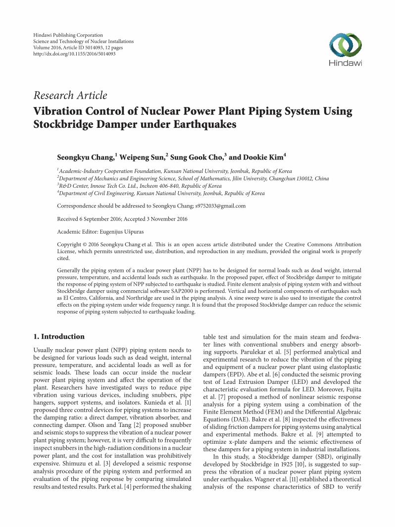
Figure 1 Nuclear power plant piping system for earthquake analysis
a theoretical predictions experimental testThe SBDwas usedto reduce the vibration of slender structures in wind such asoverhead transmission lines and stayed cables [12ndash15] Vec-chiarelli et al [12] performednumerical analysis to predict thevertical steady-state aeolian vibration of a single conductorspan attached with a Stockbridge-type damper ThereafterBarry [13] developed a finite element model to evaluate thevibrational response of a single conductor with a Stockbridgedamper and investigate the effects of the Stockbridge damperUrushadze et al [14] conducted experimental and numericalverification of wind-induced vibration of hangers on thepedestrian bridge and suggested to equip the hangers withStockbridge dampers To investigate the linear and nonlineardynamic behavior of asymmetric Stockbridge damper anexperimental test and a numerical analysis were performedby N Barbieri and R Barbieri [15]
In this study a piping system (ASCE CLASS1 SA312GRADE TP316 SCH) was installed in identical conditions tothose in a real nuclear power plant andwas used to investigatethe control performance of the SBD Finite element analysisof piping system with and without Stockbridge damperwas performed using commercial software SAP2000 A sinesweep wave was used to investigate the control effects onthe piping system under wide frequency range In order toconfirm the control effects of the Stockbridge damper underrandom earthquake vibration the three selective (El CentroCalifornia and Northridge) earthquakes were used in thisinvestigation
2 Piping System
21 Outline of Piping System The nuclear power plant pipingsystem was composed of 2- and 3-inch sized pipes the lengthof the axis of ordinates is 178m the end of the pipe tip wasfixed and 2 reducers were modeled as hinge conditions It isassumed that the inner space of the pipe was filled with waterThe water was modeled as an additional mass
Table 1 Material properties
Item Value UnitYoungrsquos modulus 199000 MPaPoissonrsquos ratio 031 mdashSteel density 7850 kgm3
Water density 1000 kgm3
Table 2 Section properties
Pipe size(in)
External diameter(mm)
Internal diameter(mm)
Thickness(mm)
2 603 428 8743 889 666 1113
Figure 1 shows the piping system modeled by SAP2000The material properties and cross-sectional properties of thepipe are shown in Tables 1 and 2 All properties were appliedas the values suggested by the design criteria
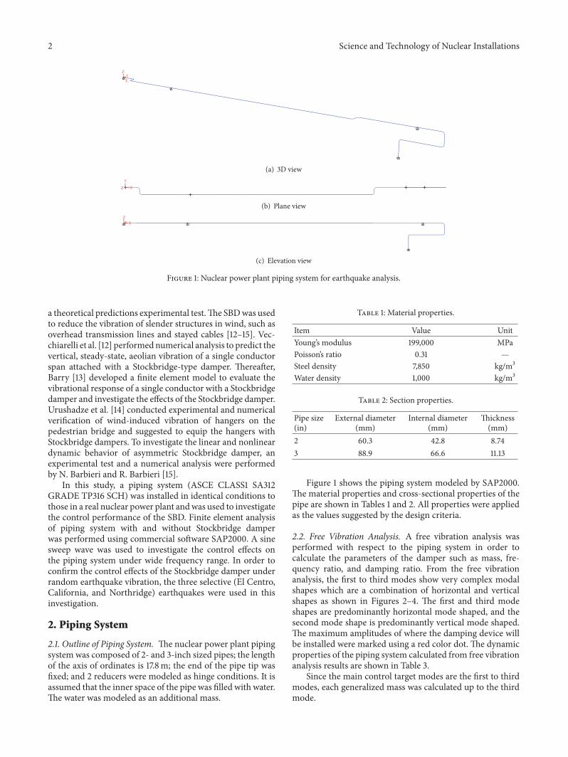
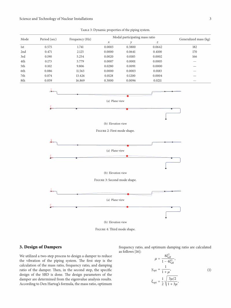
22 Free Vibration Analysis A free vibration analysis wasperformed with respect to the piping system in order tocalculate the parameters of the damper such as mass fre-quency ratio and damping ratio From the free vibrationanalysis the first to third modes show very complex modalshapes which are a combination of horizontal and verticalshapes as shown in Figures 2ndash4 The first and third modeshapes are predominantly horizontal mode shaped and thesecond mode shape is predominantly vertical mode shapedThe maximum amplitudes of where the damping device willbe installed were marked using a red color dot The dynamicproperties of the piping system calculated from free vibrationanalysis results are shown in Table 3
Since the main control target modes are the first to thirdmodes each generalized mass was calculated up to the thirdmode
Science and Technology of Nuclear Installations 3
Table 3 Dynamic properties of the piping system
Mode Period (sec) Frequency (Hz) Modal participating mass ratio Generalized mass (kg)119909 119910 1199111st 0575 1741 00003 03800 00642 1822nd 0471 2125 00000 00641 04100 1703rd 0190 5254 00020 00185 00002 1664th 0173 5779 00007 00001 00005 mdash5th 0102 9806 00280 00091 00000 mdash6th 0086 11563 00000 00003 00183 mdash7th 0074 13426 00128 01200 00004 mdash8th 0059 16869 03000 00096 00211 mdash
X
Y
Z
(a) Plane view
XY
Z
(b) Elevation view
Figure 2 First mode shape
X
Y
Z
(a) Plane view
XY
Z
(b) Elevation view
Figure 3 Second mode shape
X
Y
Z
(a) Plane view
XY
Z
(b) Elevation view
Figure 4 Third mode shape
3 Design of Dampers
We utilized a two-step process to design a damper to reducethe vibration of the piping system The first step is thecalculation of the mass ratio frequency ratio and dampingratio of the damper Then in the second step the specificdesign of the SBD is done The design parameters of thedamper are determined from the eigenvalue analysis resultsAccording to Den Hartogrsquos formula the mass ratio optimum
frequency ratio and optimum damping ratio are calculatedas follows [16]
120583 = 81205852eff1 minus 41205852eff 120574opt = 11 + 120583 120585opt = 12radic 312058321 + 3120583
(1)
4 Science and Technology of Nuclear Installations
Mass
Messenger cable
For y-direction control For z-direction control
Connection part
Piping system
Z
X
Figure 5 Components of a Stockbridge damper
where 120585eff is the effective damping ratio of the piping system120583 is the mass ratio 120574opt is the optimum frequency ratio and120585opt is the optimum damping ratio of the damper
31 Stockbridge Damper TheSBD is composed of amass partandmessenger cable parts as shown in the SBD cross sectionin Figure 5 The messenger cable is comprised of several steelwire strands and can dissipate the energy of the vibrationthrough strand friction In this paper both sides of the SBDplay a different role The left part of the SBD reduces the 119910-direction vibration of the piping system while the right partof the SBD suppresses the 119911-direction vibration of the pipingsystem
The equation of motion for SBD is given as
119872 + 119862 + 119870119909 = 0 (2)
where 119872 is the mass matrix 119862 is the damping matrix and119870 is the stiffness matrix and and 119909 are the accelerationvelocity and displacement of the SBD respectively
Undamped natural frequencies of the SBD system areobtained by [11]
1205961 = (ℎ minus 1198862119898120588 )12
1205962 = (ℎ + 1198862119898120588 )12
120588 = (119903119897 )2 ℎ = (1 + 120588) 11989611 + 119896221198972 minus 211989612119897 119886 = radicℎ2 minus 41205881198972 (1198961111989622 minus 119896212)
(3)
where 120596119894 is the frequency of the SBD 119898 is the mass 119903 isthe radius of gyration of mass 119897 is the distance betweenthe attachment point and the center of gravity of the massand 119896119894119895 is the bending stiffness of messenger cable (where119894 119895 = 1 2 3 ) The basic design for the SBD was calculatedusing the above equations and the target frequency was then
Table 4 Properties of SBD
Parameters SBD (119910-direction) SBD (119911-direction)Mass ratio 0022 0024Mass (kg) 40 40Frequency ratio 0978 0977Damping ratio 015 015Messenger cable length (m) 024 021
adjusted by fine tuning The properties of the SBD are shownin Table 4
4 Base Excitation
41 Sine Sweep Wave In order to investigate the frequencyranges of the piping system a sine sweeping wave with peakacceleration of 10msec2 varying from 01Hz to 20Hz wasapplied to the nuclear power plant piping system with andwithout the SBD for 119910- and 119911-directions (Figure 6)42 Earthquake Ground Motion In this study recordedearthquakes were used to verify that the proposed SBDcan reduce the vibration response of the nuclear powerplant piping system El Centro California and Northridgeearthquakes were selected for dynamic analysis El Centroearthquakes of the 119909- 119910- and 119911-axis direction were usedto check the horizontal and vertical behavior of the pipingsystem The earthquake time history has a 50-second dura-tion and 002-second time steps Peak ground accelerationswere scaled to 034 g 021 g and 021 g for the 119909- 119910- and 119911-axis directions respectivelyThe timehistory acceleration andresponse spectrum of the ground motion in each directionwere shown in Figure 7 While the horizontal earthquakeshave an energy distribution between 1Hz and 5Hz verticalearthquakes have more vibration energy in 10Hz
Vertical earthquakes were scaled to fit 12 of PGA of thehorizontal ground motion for California and Northridgeearthquakes Therefore the PGAs of California andNorthridge earthquakes were scaled from 015 g to 0075 gand from 034 g to 017 g in the vertical direction respectivelyThe ground motion of each direction and response spectrumare shown in Figures 8 and 9
Science and Technology of Nuclear Installations 5
0 5 10 15 20 25 30 35 40 45 50Time (sec)
0
05
1
Sweep
minus05
minus1
Acc
(ms
ec2)
(a) Sweep wave
Sweep
0 2 4 6 8 10 12 14 16 18 20Frequency (Hz)
0
05
1
15
FFT
(ms
)
(b) FFT
Figure 6 Sine sweep wave and its FFT
0 5 10 15 20 25 30 35 40 45 50
024
El Centro x-dir
0 5 10 15 20 25 30 35 40 45 50
024
El Centro y-dir
0 5 10 15 20 25 30 35 40 45 50Time (sec)
Time (sec)
Time (sec)
02
El Centro z-dir
Acc
(ms
ec2)
Acc
(ms
ec2)
Acc
(ms
ec2)
minus2
minus2
minus4
minus2
minus4
(a) El Centro earthquake
Frequency (Hz)
x-diry-dirz-dir
100
101
10minus1
0
1
2
3
4
5
6
7
8
9
Acc
(ms2)
(b) Response spectrum
Figure 7 El Centro earthquake and its FFT
5 Results and Discussion
51 Response of Piping System Subjected to Sine Sweep Excita-tion The accelerations of the piping system were measuredin the maximum amplitude when the SBD was not installedon the piping system (red spot in Figures 2ndash4) Figure 10shows the time history response and response spectrum ofthe 119910-directional response after inputting the signal in the 119910-directionThis shows that the firstmode (19Hz) is dominantHowever in the case of Figure 11 the 119911-direction responseof the piping system after applying the 119910-directional wave isshownThis simultaneously shows the peak in the first modeshape at 19Hz (119910-directional mode) and the second modeshape at 23Hz (119911-directional mode) of the piping systemunder the sine sweep wave because the modal shape of thepiping systemwasmixed Figure 13 also shows the same trendwith inverse load conditions from those in Figure 11 Figure 12
shows the same trend with Figure 10 From the results ofthe sine sweep wave it is confirmed that the proposed SBDcan reduce the vibration in all frequency domains (01 Hz to20Hz) Based on the given results it is evident that having awide frequency range is one advantage of the SBD
52 Response of Piping System Subjected to EarthquakesAn earthquake analysis was performed to investigate theapplicability with respect to the piping system and to con-firm the vibration mitigation of the piping system withand without the SBD under the recorded earthquakes Theaccelerations of the piping system were measured for themaximum amplitude when the SBD was not installed on thepiping system (red spot in Figures 2ndash4) Figure 14 shows thetime history response and frequency domain response of thepiping system with and without the SBD in the 119909- 119910- and
6 Science and Technology of Nuclear Installations
0 5 10 15 20 25 30 35 40 45 50Time (sec)
0
1
2
California y-dir
0 5 10 15 20 25 30 35 40 45 50Time (sec)
0
1
2
California z-dir
Acc
(ms
ec2)
Acc
(ms
ec2)
minus2
minus1
minus2
minus1
(a) California earthquake
Frequency (Hz)
y-dirz-dir
100
101
10minus1
0
1
2
3
4
5
6
Acc
(ms2)
(b) Response spectrum
Figure 8 California earthquake and its response spectrum
0 5 10 15 20 25 30 35 40 45 50Time (sec)
0
2
4
Northridge y-dir
0 5 10 15 20 25 30 35 40 45 50Time (sec)
0
2
4
Northridge z-dir
Acc
(ms
ec2)
Acc
(ms
ec2)
minus4
minus2
minus4
minus2
(a) Northridge earthquake
Frequency (Hz)
y-dirz-dir
100
101
10minus1
0
1
2
3
4
5
6
7
8
9
10
Acc
(ms2)
(b) Response spectrum
Figure 9 Northridge earthquake and its response spectrum
119911-axis directions when El Centro earthquake was applied tothe system
The 119909-directional vibration of the piping system appearedto be almost invisible when the SBD was installed (Fig-ure 14(a)) The maximum acceleration decreased from158ms2 to 002ms2 and the root mean square (RMS) wasreduced from 013ms2 to 0002ms2 in the 119909-direction Eachdecreasing ratio was 990 and 985 respectively In thecase of the 119910-direction response the maximum accelerationdecreased from 652ms2 to 197ms2 and RMS was reduced
from 124ms2 to 029ms2 when the SBD was appliedTable 5 shows themaximum acceleration RMS response andits decreasing ratio where the SBDwas installed In this paperthe maximum acceleration and RMS were used to evaluatethe vibration of the piping systemThe RMS are calculated asfollows
RMS = radic 1119873119873sum119899=1
1003816100381610038161003816acc11989910038161003816100381610038162 (4)
Science and Technology of Nuclear Installations 7
Table 5 Results for El Centro earthquake
Direction Maximum acceleration (ms2) RMS acceleration (ms2)Uncontrolled Controlled Decreasing ratio () Uncontrolled Controlled Decreasing ratio ()119909 1577 0016 990 0126 0002 985119910 6523 1973 698 1237 0285 769119911 3538 3145 111 0460 0260 435
Time (sec)
UncontrolledControlled
10
5
0
minus5
minus10
1009080706050403020100
Acc
(ms
ec2)
(a) Acceleration response
Frequency (Hz)
UncontrolledControlled
100
101
10minus1
0
10
20
30
40
Acc
(ms2)
(b) Response spectrum
Figure 10 Response of piping system subjected to sine sweep wave (119910-direction load and response)
Time (sec)
UncontrolledControlled
1009080706050403020100
0
2
4
Acc
(ms
ec2)
minus4
minus2
(a) Acceleration response
Frequency (Hz)
UncontrolledControlled
100
101
10minus1
0
5
10
15
20
Acc
(ms2)
(b) Response spectrum
Figure 11 Response of piping system subjected to sine sweep wave (119910-direction load versus 119911-direction response)
Time (sec)
UncontrolledControlled
1009080706050403020100
Acc
(ms
ec2)
10
5
0
minus5
minus10
(a) Acceleration response
Frequency (Hz)
UncontrolledControlled
100
101
10minus1
0
10
20
30
40
50
Acc
(ms2)
(b) Response spectrum
Figure 12 Response of piping system subjected to sine sweep wave (119911-direction load and response)
8 Science and Technology of Nuclear Installations
Time (sec)
UncontrolledControlled
1009080706050403020100
Acc
(ms
ec2)
0
2
4
minus4
minus2
(a) Acceleration response
Frequency (Hz)UncontrolledControlled
10
15
20
5
0
100
101
10minus1
Acc
(ms2)
(b) Response spectrum
Figure 13 Response of piping system subjected to sine sweep wave (119911-direction load versus 119910-direction response)
Frequency (Hz)
UncontrolledControlled
UncontrolledControlled
100
101
10minus10 5 10 15 20 25 30 35 40 45 50
Time (sec)
0
1
2
minus1
minus2
Acc
(ms
ec2)
0
1
2
3
4
5
Acc
(ms2)
(a) 119909-direction
0 5 10 15 20 25 30 35 40 45 50Time (sec)
0
5
10
Frequency (Hz)10
010
110
minus1
minus5
minus10
Acc
(ms
ec2)
UncontrolledControlled
UncontrolledControlled
0
10
20
30
40
Acc
(ms2)
(b) 119910-direction
0 5 10 15 20 25 30 35 40 45 50Time (sec)
0
2
4
Frequency (Hz)10
010
110
minus1
minus2
minus4
Acc
(ms
ec2)
UncontrolledControlled
UncontrolledControlled
0
5
10
15
Acc
(ms2)
(c) 119911-direction
Figure 14 Response of piping system subjected to El Centro earthquake
Science and Technology of Nuclear Installations 9
0 5 10 15 20 25 30 35 40 45 50Time (sec)
0
2
4
Frequency (Hz)10
010
110
minus1
minus2
minus4
UncontrolledControlled
UncontrolledControlled
Acc
(ms
ec2)
0
5
10
15
20
Acc
(ms2)
(a) 119910-direction
Time (sec)0 5 10 15 20 25 30 35 40 45 50
0
1
2
3
Frequency (Hz)
0
2
4
6
8
10
100
101
10minus1
minus1
minus2
minus3
UncontrolledControlled
UncontrolledControlled
Acc
(ms
ec2)
Acc
(ms2)
(b) 119911-direction
Figure 15 Response of piping system subjected to California earthquake
where 119873 is the length of data and acc119899 is the acceleration of119899th time stepThe RMS represents the amplitude related withan energy amount which indicates the destructive ability ofthe vibration
The 119911-directional El Centro earthquake shows a largeamount of energy on the adjacent 10Hz unlike earth-quakes of the other directions (Figure 7(a)) Although theproposed SBD was not designed with respect to that fre-quency area nevertheless the control effects of the dampercan be confirmed based on the peak acceleration andresponse spectrum Since the SBD was not designed for 119909-directional response the control system has some effectson the responses of 119909-directions This phenomenon can beexplained by the reason of the piping system having complexmodal shapes and coupled responses In other words if 119910-direction and 119911-direction responses of the piping system canoccur by earthquake in 119909-direction then it is obvious thatthe SBD can be capable of suppressing the vibration in 119909-direction with the other both directions instead of not beingdesigned for 119909-direction
Figures 15 and 16 show the time history response andfrequency domain response of the nuclear power plant pipingsystem with and without the SBD in the 119910- and 119911-axisdirections under California andNorthridge earthquakesTheacceleration response of both earthquakes was considerablysuppressed by the proposed SBD With respect to Californiaearthquake the maximum acceleration of the piping system
decreased from 322ms2 to 117ms2 and RMS response wasreduced from 067ms2 to 019ms2 in the 119910-direction Eachdecreasing ratio was 638 and 716 respectively In thecase of the 119911-direction the decreasing ratio of the maximumacceleration and RMS response decreased by 743 and734 respectively
This demonstrates the good control performance of theSBD for Northridge earthquake as shown in Figure 16The maximum acceleration and RMS response decreased by602 and 740 in the 119910-direction respectively and 585and 719 in the 119911-direction respectively The maximumacceleration and RMS response for each earthquake areshown in Tables 6 and 7
Figure 17 shows the response of the piping system in the 119911-direction under the 119910-directional El Centro earthquake andthe response of the piping system in the 119910-direction underthe 119911-directional El Centro earthquake It can be seen thatthe response reduction of the piping system in Figure 17is more noticeable than the trend shown in Figures 14ndash16 While the control effects of the SBD in Figures 14ndash16show extremely effective behavior at tuned frequencies (firstand second mode) the frequency response of Figure 17 is2Hz which shows a wide range of frequency response Theresponse decreasing ratio of the piping systemwas largewhenthe load direction and response direction were differentThis is because the SBD in this paper was actually designedfor first and second frequency modes therefore the SBD
10 Science and Technology of Nuclear Installations
Table 6 Results for California earthquake
Direction Maximum acceleration (ms2) RMS acceleration (ms2)Uncontrolled Controlled Decreasing ratio () Uncontrolled Controlled Decreasing ratio ()119910 3217 1165 638 0667 0190 716119911 2256 0580 743 0350 0093 734
Table 7 Results for Northridge earthquake
Direction Maximum acceleration (ms2) RMS acceleration (ms2)Uncontrolled Controlled Decreasing ratio () Uncontrolled Controlled Decreasing ratio ()119910 7252 2889 602 1190 0310 740119911 3576 1484 585 0545 0153 719
Time (sec)0 5 10 15 20 25 30 35 40 45 50
0
5
10
Frequency (Hz)10
010
110
minus1
minus5
minus10
UncontrolledControlled
UncontrolledControlled
Acc
(ms
ec2)
0
10
20
30
40
Acc
(ms2)
(a) 119910-direction
Time (sec)0 5 10 15 20 25 30 35 40 45 50
0
2
4
Frequency (Hz)10
010
110
minus1
minus2
minus4
UncontrolledControlled
UncontrolledControlled
Acc
(ms
ec2)
0
5
10
15
20
Acc
(ms2)
(b) 119911-direction
Figure 16 Response of piping system subjected to Northridge earthquake
extremely suppressed the vibration of the piping systemHowever that the SBD can also reduce vibrations beyondthe design frequency range was already confirmed in ourprevious results The results of California earthquake alsoshow a similar trend with those of El Centro earthquake(Figure 18) The directional results for both earthquakes aresummarized in Tables 8 and 9 The reduction ratio of allresponses is more than 90
6 ConclusionFrom the study performed SBD is recommended to controlthe seismic response of NPP piping system Effect of SBD
to control the seismic response of piping system is demon-strated considering El Centro California and Northridgeearthquake excitations The piping system (ASCE CLASS1SA312 GRADE TP316 SCH) was modeled under the sameconditions as in an actual nuclear power plant The SBD wasdesigned for low order frequency modes using free vibra-tion analysis results The controlled responses of the timeand frequency domain were compared with uncontrolledresponses of the piping system under horizontal and verticalearthquakes It was confirmed through sine sweep waveanalysis that the proposed damper can reducewide frequencyvibration responses
Science and Technology of Nuclear Installations 11
0 5 10 15 20 25 30 35 40 45 50
0
05
1
Frequency (Hz)Time (sec)10
010
110
minus1
minus05
minus1
UncontrolledControlled
UncontrolledControlled
Acc
(ms
ec2)
0
1
2
3
4
5
Acc
(ms2)
(a) 119910-direction response under 119911-direction load
0 5 10 15 20 25 30 35 40 45 50
0
2
4
Frequency (Hz)Time (sec)10
010
110
minus1
minus2
minus4
UncontrolledControlled
UncontrolledControlled
Acc
(ms
ec2)
0
5
10
15
20
Acc
(ms2)
(b) 119911-direction response under 119910-direction load
Figure 17 Response of piping system subjected to El Centro earthquake
0 5 10 15 20 25 30 35 40 45 50
0
05
1
Frequency (Hz)Time (sec)10
010
110
minus1
minus05
minus1
UncontrolledControlled
UncontrolledControlled
Acc
(ms
ec2)
0
1
2
3
4
5
Acc
(ms2)
(a) 119910-direction response under 119911-direction load
0 5 10 15 20 25 30 35 40 45 50
0
1
2
Frequency (Hz)Time (sec)10
010
110
minus1
minus1
minus2
UncontrolledControlled
UncontrolledControlled
Acc
(ms
ec2)
0
2
4
6
8
10
Acc
(ms2)
(b) 119911-direction response under 119910-direction load
Figure 18 Response of piping system subjected to California earthquake
12 Science and Technology of Nuclear Installations
Table 8 Directional results for El Centro earthquake
Direction Maximum acceleration (ms2) RMS acceleration (ms2)Load Resp Uncontrolled Controlled Decreasing ratio () Uncontrolled Controlled Decreasing ratio ()119911 119910 0838 0082 903 0169 0008 952119910 119911 3132 0114 963 0618 0018 971
Table 9 Directional results for California earthquake
Direction Maximum acceleration (ms2) RMS acceleration (ms2)Load Resp Uncontrolled Controlled Decreasing ratio () Uncontrolled Controlled Decreasing ratio ()119911 119910 0745 0043 942 0151 0006 960119910 119911 1527 0085 945 0306 0012 961
In the earthquake results the maximum accelerationdeclined by about 99 69 and 11 in each directionunder El Centro earthquake respectively The maximumaccelerations decreased by 63 in 119910-direction and 74 in119911-direction under California earthquake In the case of theNorthridge earthquake reductions of each acceleration werefound to be 60 and 58 in 119910-direction and 119911-directionsuccessively
From the earthquake response analysis results it wasfound that the proposed SBD can reduce not only the targetedvibration modes of the piping system but also other modesunder earthquakes Most importantly it was also confirmedthat the proposed SBD can effectively reduce the vibration ofa nuclear power plant piping system under earthquakes
Competing Interests
The authors declare that they have no competing interests
Acknowledgments
This work was supported by the National Research Foun-dation of Korea Grant funded by the Korean Government(NRF-2014R1A2A1A10049538) and the Nuclear Power CoreTechnology Development Program of the Korea Institute ofEnergy Technology Evaluation and Planning (KETEP) grantfinancial resource from the Ministry of Trade Industry ampEnergy Republic of Korea (no 20131520400080)
References
[1] M Kunieda T Chiba and H Kobayashi ldquoPositive use ofdamping devices for piping systemsmdashsome experiences andnew proposalsrdquo Nuclear Engineering and Design vol 104 no2 pp 107ndash120 1987
[2] D E Olson and Y K Tang ldquoDecreasing snubber inserviceinspection costs through snubber reduction and improved testlimitsrdquoNuclear Engineering andDesign vol 107 no 1-2 pp 183ndash199 1988
[3] N Shimuzu K Suzuki T Watanabe N Ogawa and HKobayashi ldquoLarge scale shaking table test on modal responsesof 3D piping system with friction supportrdquo Seismic EngineeringASME PVP vol 340 pp 269ndash275 1996
[4] N Park G DeGrassi C Hofmayer and P Bezler ldquoAnalysisof nuclear piping system seismic tests with conventional and
energy absorbing supportsrdquo in Proceedings of the InternationalConference on Structural Mechanics in Reactor Technology pp269ndash275 Lyon France 1997
[5] Y M Parulekar G R Reddy K K Vaze and H S KushwahaldquoElasto-plastic damper for passive control of seismic responseof piping systemsrdquo BARC Internal Report Reactor SafetyDivision 2002
[6] HAbe I Ichihashi K Kuroda T Iwatsubo andK Tai ldquoSeismicproving test of heavy component with energy absorbing sup-portrdquo in Proceedings of the International Conference on GlobalEnvironment and Advanced Nuclear Power Plants Kyoto JapanSeptember 2003
[7] K Fujita T Kimura and Y Ohe ldquoSeismic response analysisof piping systems with nonlinear supports using differentialalgebraic equationsrdquo Journal of Pressure Vessel TechnologyTransactions of the ASME vol 126 no 1 pp 91ndash97 2004
[8] S V Bakre R S Jangid and G R Reddy ldquoSeismic response ofpiping system with isolation devicesrdquo in Proceedings of the 13thWorld Conference on Earthquake Engineering Paper no 2676Vancouver Canada August 2004
[9] S V Bakre R S Jangid and G R Reddy ldquoOptimum X-platedampers for seismic response control of piping systemsrdquo inProceedings of the 4th International Conference on StructuralStability and Dynamics 2012
[10] G Stockbridge ldquoVibration Damperrdquo Patent No 1675391 USAPatent Office 1925
[11] H Wagner V Ramamurti R V R Sastry and K HartmannldquoDynamics of stockbridge dampersrdquo Journal of Sound andVibration vol 30 no 2 pp 207ndash220 1973
[12] J Vecchiarelli I G Currie and D G Havard ldquoComputationalanalysis of aeolian conductor vibration with a stockbridge-typedamperrdquo Journal of Fluids and Structures vol 14 no 4 pp 489ndash509 2000
[13] O Barry Finite element analysis of a single conductor with a stockbridge damper under aeolian vibration [MS thesis] RyersonUniversity 2010
[14] S Urushadze M Pirner S Pospisil and R Kral ldquoExperimentaland numerical verification of vortex-induced vibration of hang-ers on the footbridgerdquo in Proceedings of the 18th InternationalConference Engineering Mechanics Svratka Czech Republic2012
[15] N Barbieri and R Barbieri ldquoDynamic analysis of stockbridgedamperrdquo Advances in Acoustics and Vibration vol 2012 ArticleID 659398 8 pages 2012
[16] J P Den Hartog Mechanical Vibrations McGraw-Hill BookCompany New York NY USA 3rd edition 1947
TribologyAdvances in
Hindawi Publishing Corporationhttpwwwhindawicom Volume 2014
International Journal of
AerospaceEngineeringHindawi Publishing Corporationhttpwwwhindawicom Volume 2014
FuelsJournal of
Hindawi Publishing Corporationhttpwwwhindawicom Volume 2014
Journal ofPetroleum Engineering
Hindawi Publishing Corporationhttpwwwhindawicom Volume 2014
Industrial EngineeringJournal of
Hindawi Publishing Corporationhttpwwwhindawicom Volume 2014
Power ElectronicsHindawi Publishing Corporationhttpwwwhindawicom Volume 2014
Advances in
CombustionJournal of
Hindawi Publishing Corporationhttpwwwhindawicom Volume 2014
Journal of
Hindawi Publishing Corporationhttpwwwhindawicom Volume 2014
Renewable Energy
Submit your manuscripts athttpwwwhindawicom
Hindawi Publishing Corporationhttpwwwhindawicom Volume 2014
StructuresJournal of
International Journal of
RotatingMachinery
Hindawi Publishing Corporationhttpwwwhindawicom Volume 2014
EnergyJournal of
Hindawi Publishing Corporationhttpwwwhindawicom Volume 2014
Hindawi Publishing Corporation httpwwwhindawicom
Journal ofEngineeringVolume 2014
Hindawi Publishing Corporation httpwwwhindawicom Volume 2014
International Journal ofPhotoenergy
Hindawi Publishing Corporationhttpwwwhindawicom Volume 2014
Nuclear InstallationsScience and Technology of
Hindawi Publishing Corporationhttpwwwhindawicom Volume 2014
Solar EnergyJournal of
Hindawi Publishing Corporationhttpwwwhindawicom Volume 2014
Wind EnergyJournal of
Hindawi Publishing Corporationhttpwwwhindawicom Volume 2014
Nuclear EnergyInternational Journal of
Hindawi Publishing Corporationhttpwwwhindawicom Volume 2014
High Energy PhysicsAdvances in
The Scientific World JournalHindawi Publishing Corporation httpwwwhindawicom Volume 2014
2 Science and Technology of Nuclear Installations
X
Y
Z
(a) 3D view
X
Y
Z
(b) Plane view
XY
Z
(c) Elevation view
Figure 1 Nuclear power plant piping system for earthquake analysis
a theoretical predictions experimental testThe SBDwas usedto reduce the vibration of slender structures in wind such asoverhead transmission lines and stayed cables [12ndash15] Vec-chiarelli et al [12] performednumerical analysis to predict thevertical steady-state aeolian vibration of a single conductorspan attached with a Stockbridge-type damper ThereafterBarry [13] developed a finite element model to evaluate thevibrational response of a single conductor with a Stockbridgedamper and investigate the effects of the Stockbridge damperUrushadze et al [14] conducted experimental and numericalverification of wind-induced vibration of hangers on thepedestrian bridge and suggested to equip the hangers withStockbridge dampers To investigate the linear and nonlineardynamic behavior of asymmetric Stockbridge damper anexperimental test and a numerical analysis were performedby N Barbieri and R Barbieri [15]
In this study a piping system (ASCE CLASS1 SA312GRADE TP316 SCH) was installed in identical conditions tothose in a real nuclear power plant andwas used to investigatethe control performance of the SBD Finite element analysisof piping system with and without Stockbridge damperwas performed using commercial software SAP2000 A sinesweep wave was used to investigate the control effects onthe piping system under wide frequency range In order toconfirm the control effects of the Stockbridge damper underrandom earthquake vibration the three selective (El CentroCalifornia and Northridge) earthquakes were used in thisinvestigation
2 Piping System
21 Outline of Piping System The nuclear power plant pipingsystem was composed of 2- and 3-inch sized pipes the lengthof the axis of ordinates is 178m the end of the pipe tip wasfixed and 2 reducers were modeled as hinge conditions It isassumed that the inner space of the pipe was filled with waterThe water was modeled as an additional mass
Table 1 Material properties
Item Value UnitYoungrsquos modulus 199000 MPaPoissonrsquos ratio 031 mdashSteel density 7850 kgm3
Water density 1000 kgm3
Table 2 Section properties
Pipe size(in)
External diameter(mm)
Internal diameter(mm)
Thickness(mm)
2 603 428 8743 889 666 1113
Figure 1 shows the piping system modeled by SAP2000The material properties and cross-sectional properties of thepipe are shown in Tables 1 and 2 All properties were appliedas the values suggested by the design criteria
22 Free Vibration Analysis A free vibration analysis wasperformed with respect to the piping system in order tocalculate the parameters of the damper such as mass fre-quency ratio and damping ratio From the free vibrationanalysis the first to third modes show very complex modalshapes which are a combination of horizontal and verticalshapes as shown in Figures 2ndash4 The first and third modeshapes are predominantly horizontal mode shaped and thesecond mode shape is predominantly vertical mode shapedThe maximum amplitudes of where the damping device willbe installed were marked using a red color dot The dynamicproperties of the piping system calculated from free vibrationanalysis results are shown in Table 3
Since the main control target modes are the first to thirdmodes each generalized mass was calculated up to the thirdmode
Science and Technology of Nuclear Installations 3
Table 3 Dynamic properties of the piping system
Mode Period (sec) Frequency (Hz) Modal participating mass ratio Generalized mass (kg)119909 119910 1199111st 0575 1741 00003 03800 00642 1822nd 0471 2125 00000 00641 04100 1703rd 0190 5254 00020 00185 00002 1664th 0173 5779 00007 00001 00005 mdash5th 0102 9806 00280 00091 00000 mdash6th 0086 11563 00000 00003 00183 mdash7th 0074 13426 00128 01200 00004 mdash8th 0059 16869 03000 00096 00211 mdash
X
Y
Z
(a) Plane view
XY
Z
(b) Elevation view
Figure 2 First mode shape
X
Y
Z
(a) Plane view
XY
Z
(b) Elevation view
Figure 3 Second mode shape
X
Y
Z
(a) Plane view
XY
Z
(b) Elevation view
Figure 4 Third mode shape
3 Design of Dampers
We utilized a two-step process to design a damper to reducethe vibration of the piping system The first step is thecalculation of the mass ratio frequency ratio and dampingratio of the damper Then in the second step the specificdesign of the SBD is done The design parameters of thedamper are determined from the eigenvalue analysis resultsAccording to Den Hartogrsquos formula the mass ratio optimum
frequency ratio and optimum damping ratio are calculatedas follows [16]
120583 = 81205852eff1 minus 41205852eff 120574opt = 11 + 120583 120585opt = 12radic 312058321 + 3120583
(1)
4 Science and Technology of Nuclear Installations
Mass
Messenger cable
For y-direction control For z-direction control
Connection part
Piping system
Z
X
Figure 5 Components of a Stockbridge damper
where 120585eff is the effective damping ratio of the piping system120583 is the mass ratio 120574opt is the optimum frequency ratio and120585opt is the optimum damping ratio of the damper
31 Stockbridge Damper TheSBD is composed of amass partandmessenger cable parts as shown in the SBD cross sectionin Figure 5 The messenger cable is comprised of several steelwire strands and can dissipate the energy of the vibrationthrough strand friction In this paper both sides of the SBDplay a different role The left part of the SBD reduces the 119910-direction vibration of the piping system while the right partof the SBD suppresses the 119911-direction vibration of the pipingsystem
The equation of motion for SBD is given as
119872 + 119862 + 119870119909 = 0 (2)
where 119872 is the mass matrix 119862 is the damping matrix and119870 is the stiffness matrix and and 119909 are the accelerationvelocity and displacement of the SBD respectively
Undamped natural frequencies of the SBD system areobtained by [11]
1205961 = (ℎ minus 1198862119898120588 )12
1205962 = (ℎ + 1198862119898120588 )12
120588 = (119903119897 )2 ℎ = (1 + 120588) 11989611 + 119896221198972 minus 211989612119897 119886 = radicℎ2 minus 41205881198972 (1198961111989622 minus 119896212)
(3)
where 120596119894 is the frequency of the SBD 119898 is the mass 119903 isthe radius of gyration of mass 119897 is the distance betweenthe attachment point and the center of gravity of the massand 119896119894119895 is the bending stiffness of messenger cable (where119894 119895 = 1 2 3 ) The basic design for the SBD was calculatedusing the above equations and the target frequency was then
Table 4 Properties of SBD
Parameters SBD (119910-direction) SBD (119911-direction)Mass ratio 0022 0024Mass (kg) 40 40Frequency ratio 0978 0977Damping ratio 015 015Messenger cable length (m) 024 021
adjusted by fine tuning The properties of the SBD are shownin Table 4
4 Base Excitation
41 Sine Sweep Wave In order to investigate the frequencyranges of the piping system a sine sweeping wave with peakacceleration of 10msec2 varying from 01Hz to 20Hz wasapplied to the nuclear power plant piping system with andwithout the SBD for 119910- and 119911-directions (Figure 6)42 Earthquake Ground Motion In this study recordedearthquakes were used to verify that the proposed SBDcan reduce the vibration response of the nuclear powerplant piping system El Centro California and Northridgeearthquakes were selected for dynamic analysis El Centroearthquakes of the 119909- 119910- and 119911-axis direction were usedto check the horizontal and vertical behavior of the pipingsystem The earthquake time history has a 50-second dura-tion and 002-second time steps Peak ground accelerationswere scaled to 034 g 021 g and 021 g for the 119909- 119910- and 119911-axis directions respectivelyThe timehistory acceleration andresponse spectrum of the ground motion in each directionwere shown in Figure 7 While the horizontal earthquakeshave an energy distribution between 1Hz and 5Hz verticalearthquakes have more vibration energy in 10Hz
Vertical earthquakes were scaled to fit 12 of PGA of thehorizontal ground motion for California and Northridgeearthquakes Therefore the PGAs of California andNorthridge earthquakes were scaled from 015 g to 0075 gand from 034 g to 017 g in the vertical direction respectivelyThe ground motion of each direction and response spectrumare shown in Figures 8 and 9
Science and Technology of Nuclear Installations 5
0 5 10 15 20 25 30 35 40 45 50Time (sec)
0
05
1
Sweep
minus05
minus1
Acc
(ms
ec2)
(a) Sweep wave
Sweep
0 2 4 6 8 10 12 14 16 18 20Frequency (Hz)
0
05
1
15
FFT
(ms
)
(b) FFT
Figure 6 Sine sweep wave and its FFT
0 5 10 15 20 25 30 35 40 45 50
024
El Centro x-dir
0 5 10 15 20 25 30 35 40 45 50
024
El Centro y-dir
0 5 10 15 20 25 30 35 40 45 50Time (sec)
Time (sec)
Time (sec)
02
El Centro z-dir
Acc
(ms
ec2)
Acc
(ms
ec2)
Acc
(ms
ec2)
minus2
minus2
minus4
minus2
minus4
(a) El Centro earthquake
Frequency (Hz)
x-diry-dirz-dir
100
101
10minus1
0
1
2
3
4
5
6
7
8
9
Acc
(ms2)
(b) Response spectrum
Figure 7 El Centro earthquake and its FFT
5 Results and Discussion
51 Response of Piping System Subjected to Sine Sweep Excita-tion The accelerations of the piping system were measuredin the maximum amplitude when the SBD was not installedon the piping system (red spot in Figures 2ndash4) Figure 10shows the time history response and response spectrum ofthe 119910-directional response after inputting the signal in the 119910-directionThis shows that the firstmode (19Hz) is dominantHowever in the case of Figure 11 the 119911-direction responseof the piping system after applying the 119910-directional wave isshownThis simultaneously shows the peak in the first modeshape at 19Hz (119910-directional mode) and the second modeshape at 23Hz (119911-directional mode) of the piping systemunder the sine sweep wave because the modal shape of thepiping systemwasmixed Figure 13 also shows the same trendwith inverse load conditions from those in Figure 11 Figure 12
shows the same trend with Figure 10 From the results ofthe sine sweep wave it is confirmed that the proposed SBDcan reduce the vibration in all frequency domains (01 Hz to20Hz) Based on the given results it is evident that having awide frequency range is one advantage of the SBD
52 Response of Piping System Subjected to EarthquakesAn earthquake analysis was performed to investigate theapplicability with respect to the piping system and to con-firm the vibration mitigation of the piping system withand without the SBD under the recorded earthquakes Theaccelerations of the piping system were measured for themaximum amplitude when the SBD was not installed on thepiping system (red spot in Figures 2ndash4) Figure 14 shows thetime history response and frequency domain response of thepiping system with and without the SBD in the 119909- 119910- and
6 Science and Technology of Nuclear Installations
0 5 10 15 20 25 30 35 40 45 50Time (sec)
0
1
2
California y-dir
0 5 10 15 20 25 30 35 40 45 50Time (sec)
0
1
2
California z-dir
Acc
(ms
ec2)
Acc
(ms
ec2)
minus2
minus1
minus2
minus1
(a) California earthquake
Frequency (Hz)
y-dirz-dir
100
101
10minus1
0
1
2
3
4
5
6
Acc
(ms2)
(b) Response spectrum
Figure 8 California earthquake and its response spectrum
0 5 10 15 20 25 30 35 40 45 50Time (sec)
0
2
4
Northridge y-dir
0 5 10 15 20 25 30 35 40 45 50Time (sec)
0
2
4
Northridge z-dir
Acc
(ms
ec2)
Acc
(ms
ec2)
minus4
minus2
minus4
minus2
(a) Northridge earthquake
Frequency (Hz)
y-dirz-dir
100
101
10minus1
0
1
2
3
4
5
6
7
8
9
10
Acc
(ms2)
(b) Response spectrum
Figure 9 Northridge earthquake and its response spectrum
119911-axis directions when El Centro earthquake was applied tothe system
The 119909-directional vibration of the piping system appearedto be almost invisible when the SBD was installed (Fig-ure 14(a)) The maximum acceleration decreased from158ms2 to 002ms2 and the root mean square (RMS) wasreduced from 013ms2 to 0002ms2 in the 119909-direction Eachdecreasing ratio was 990 and 985 respectively In thecase of the 119910-direction response the maximum accelerationdecreased from 652ms2 to 197ms2 and RMS was reduced
from 124ms2 to 029ms2 when the SBD was appliedTable 5 shows themaximum acceleration RMS response andits decreasing ratio where the SBDwas installed In this paperthe maximum acceleration and RMS were used to evaluatethe vibration of the piping systemThe RMS are calculated asfollows
RMS = radic 1119873119873sum119899=1
1003816100381610038161003816acc11989910038161003816100381610038162 (4)
Science and Technology of Nuclear Installations 7
Table 5 Results for El Centro earthquake
Direction Maximum acceleration (ms2) RMS acceleration (ms2)Uncontrolled Controlled Decreasing ratio () Uncontrolled Controlled Decreasing ratio ()119909 1577 0016 990 0126 0002 985119910 6523 1973 698 1237 0285 769119911 3538 3145 111 0460 0260 435
Time (sec)
UncontrolledControlled
10
5
0
minus5
minus10
1009080706050403020100
Acc
(ms
ec2)
(a) Acceleration response
Frequency (Hz)
UncontrolledControlled
100
101
10minus1
0
10
20
30
40
Acc
(ms2)
(b) Response spectrum
Figure 10 Response of piping system subjected to sine sweep wave (119910-direction load and response)
Time (sec)
UncontrolledControlled
1009080706050403020100
0
2
4
Acc
(ms
ec2)
minus4
minus2
(a) Acceleration response
Frequency (Hz)
UncontrolledControlled
100
101
10minus1
0
5
10
15
20
Acc
(ms2)
(b) Response spectrum
Figure 11 Response of piping system subjected to sine sweep wave (119910-direction load versus 119911-direction response)
Time (sec)
UncontrolledControlled
1009080706050403020100
Acc
(ms
ec2)
10
5
0
minus5
minus10
(a) Acceleration response
Frequency (Hz)
UncontrolledControlled
100
101
10minus1
0
10
20
30
40
50
Acc
(ms2)
(b) Response spectrum
Figure 12 Response of piping system subjected to sine sweep wave (119911-direction load and response)
8 Science and Technology of Nuclear Installations
Time (sec)
UncontrolledControlled
1009080706050403020100
Acc
(ms
ec2)
0
2
4
minus4
minus2
(a) Acceleration response
Frequency (Hz)UncontrolledControlled
10
15
20
5
0
100
101
10minus1
Acc
(ms2)
(b) Response spectrum
Figure 13 Response of piping system subjected to sine sweep wave (119911-direction load versus 119910-direction response)
Frequency (Hz)
UncontrolledControlled
UncontrolledControlled
100
101
10minus10 5 10 15 20 25 30 35 40 45 50
Time (sec)
0
1
2
minus1
minus2
Acc
(ms
ec2)
0
1
2
3
4
5
Acc
(ms2)
(a) 119909-direction
0 5 10 15 20 25 30 35 40 45 50Time (sec)
0
5
10
Frequency (Hz)10
010
110
minus1
minus5
minus10
Acc
(ms
ec2)
UncontrolledControlled
UncontrolledControlled
0
10
20
30
40
Acc
(ms2)
(b) 119910-direction
0 5 10 15 20 25 30 35 40 45 50Time (sec)
0
2
4
Frequency (Hz)10
010
110
minus1
minus2
minus4
Acc
(ms
ec2)
UncontrolledControlled
UncontrolledControlled
0
5
10
15
Acc
(ms2)
(c) 119911-direction
Figure 14 Response of piping system subjected to El Centro earthquake
Science and Technology of Nuclear Installations 9
0 5 10 15 20 25 30 35 40 45 50Time (sec)
0
2
4
Frequency (Hz)10
010
110
minus1
minus2
minus4
UncontrolledControlled
UncontrolledControlled
Acc
(ms
ec2)
0
5
10
15
20
Acc
(ms2)
(a) 119910-direction
Time (sec)0 5 10 15 20 25 30 35 40 45 50
0
1
2
3
Frequency (Hz)
0
2
4
6
8
10
100
101
10minus1
minus1
minus2
minus3
UncontrolledControlled
UncontrolledControlled
Acc
(ms
ec2)
Acc
(ms2)
(b) 119911-direction
Figure 15 Response of piping system subjected to California earthquake
where 119873 is the length of data and acc119899 is the acceleration of119899th time stepThe RMS represents the amplitude related withan energy amount which indicates the destructive ability ofthe vibration
The 119911-directional El Centro earthquake shows a largeamount of energy on the adjacent 10Hz unlike earth-quakes of the other directions (Figure 7(a)) Although theproposed SBD was not designed with respect to that fre-quency area nevertheless the control effects of the dampercan be confirmed based on the peak acceleration andresponse spectrum Since the SBD was not designed for 119909-directional response the control system has some effectson the responses of 119909-directions This phenomenon can beexplained by the reason of the piping system having complexmodal shapes and coupled responses In other words if 119910-direction and 119911-direction responses of the piping system canoccur by earthquake in 119909-direction then it is obvious thatthe SBD can be capable of suppressing the vibration in 119909-direction with the other both directions instead of not beingdesigned for 119909-direction
Figures 15 and 16 show the time history response andfrequency domain response of the nuclear power plant pipingsystem with and without the SBD in the 119910- and 119911-axisdirections under California andNorthridge earthquakesTheacceleration response of both earthquakes was considerablysuppressed by the proposed SBD With respect to Californiaearthquake the maximum acceleration of the piping system
decreased from 322ms2 to 117ms2 and RMS response wasreduced from 067ms2 to 019ms2 in the 119910-direction Eachdecreasing ratio was 638 and 716 respectively In thecase of the 119911-direction the decreasing ratio of the maximumacceleration and RMS response decreased by 743 and734 respectively
This demonstrates the good control performance of theSBD for Northridge earthquake as shown in Figure 16The maximum acceleration and RMS response decreased by602 and 740 in the 119910-direction respectively and 585and 719 in the 119911-direction respectively The maximumacceleration and RMS response for each earthquake areshown in Tables 6 and 7
Figure 17 shows the response of the piping system in the 119911-direction under the 119910-directional El Centro earthquake andthe response of the piping system in the 119910-direction underthe 119911-directional El Centro earthquake It can be seen thatthe response reduction of the piping system in Figure 17is more noticeable than the trend shown in Figures 14ndash16 While the control effects of the SBD in Figures 14ndash16show extremely effective behavior at tuned frequencies (firstand second mode) the frequency response of Figure 17 is2Hz which shows a wide range of frequency response Theresponse decreasing ratio of the piping systemwas largewhenthe load direction and response direction were differentThis is because the SBD in this paper was actually designedfor first and second frequency modes therefore the SBD
10 Science and Technology of Nuclear Installations
Table 6 Results for California earthquake
Direction Maximum acceleration (ms2) RMS acceleration (ms2)Uncontrolled Controlled Decreasing ratio () Uncontrolled Controlled Decreasing ratio ()119910 3217 1165 638 0667 0190 716119911 2256 0580 743 0350 0093 734
Table 7 Results for Northridge earthquake
Direction Maximum acceleration (ms2) RMS acceleration (ms2)Uncontrolled Controlled Decreasing ratio () Uncontrolled Controlled Decreasing ratio ()119910 7252 2889 602 1190 0310 740119911 3576 1484 585 0545 0153 719
Time (sec)0 5 10 15 20 25 30 35 40 45 50
0
5
10
Frequency (Hz)10
010
110
minus1
minus5
minus10
UncontrolledControlled
UncontrolledControlled
Acc
(ms
ec2)
0
10
20
30
40
Acc
(ms2)
(a) 119910-direction
Time (sec)0 5 10 15 20 25 30 35 40 45 50
0
2
4
Frequency (Hz)10
010
110
minus1
minus2
minus4
UncontrolledControlled
UncontrolledControlled
Acc
(ms
ec2)
0
5
10
15
20
Acc
(ms2)
(b) 119911-direction
Figure 16 Response of piping system subjected to Northridge earthquake
extremely suppressed the vibration of the piping systemHowever that the SBD can also reduce vibrations beyondthe design frequency range was already confirmed in ourprevious results The results of California earthquake alsoshow a similar trend with those of El Centro earthquake(Figure 18) The directional results for both earthquakes aresummarized in Tables 8 and 9 The reduction ratio of allresponses is more than 90
6 ConclusionFrom the study performed SBD is recommended to controlthe seismic response of NPP piping system Effect of SBD
to control the seismic response of piping system is demon-strated considering El Centro California and Northridgeearthquake excitations The piping system (ASCE CLASS1SA312 GRADE TP316 SCH) was modeled under the sameconditions as in an actual nuclear power plant The SBD wasdesigned for low order frequency modes using free vibra-tion analysis results The controlled responses of the timeand frequency domain were compared with uncontrolledresponses of the piping system under horizontal and verticalearthquakes It was confirmed through sine sweep waveanalysis that the proposed damper can reducewide frequencyvibration responses
Science and Technology of Nuclear Installations 11
0 5 10 15 20 25 30 35 40 45 50
0
05
1
Frequency (Hz)Time (sec)10
010
110
minus1
minus05
minus1
UncontrolledControlled
UncontrolledControlled
Acc
(ms
ec2)
0
1
2
3
4
5
Acc
(ms2)
(a) 119910-direction response under 119911-direction load
0 5 10 15 20 25 30 35 40 45 50
0
2
4
Frequency (Hz)Time (sec)10
010
110
minus1
minus2
minus4
UncontrolledControlled
UncontrolledControlled
Acc
(ms
ec2)
0
5
10
15
20
Acc
(ms2)
(b) 119911-direction response under 119910-direction load
Figure 17 Response of piping system subjected to El Centro earthquake
0 5 10 15 20 25 30 35 40 45 50
0
05
1
Frequency (Hz)Time (sec)10
010
110
minus1
minus05
minus1
UncontrolledControlled
UncontrolledControlled
Acc
(ms
ec2)
0
1
2
3
4
5
Acc
(ms2)
(a) 119910-direction response under 119911-direction load
0 5 10 15 20 25 30 35 40 45 50
0
1
2
Frequency (Hz)Time (sec)10
010
110
minus1
minus1
minus2
UncontrolledControlled
UncontrolledControlled
Acc
(ms
ec2)
0
2
4
6
8
10
Acc
(ms2)
(b) 119911-direction response under 119910-direction load
Figure 18 Response of piping system subjected to California earthquake
12 Science and Technology of Nuclear Installations
Table 8 Directional results for El Centro earthquake
Direction Maximum acceleration (ms2) RMS acceleration (ms2)Load Resp Uncontrolled Controlled Decreasing ratio () Uncontrolled Controlled Decreasing ratio ()119911 119910 0838 0082 903 0169 0008 952119910 119911 3132 0114 963 0618 0018 971
Table 9 Directional results for California earthquake
Direction Maximum acceleration (ms2) RMS acceleration (ms2)Load Resp Uncontrolled Controlled Decreasing ratio () Uncontrolled Controlled Decreasing ratio ()119911 119910 0745 0043 942 0151 0006 960119910 119911 1527 0085 945 0306 0012 961
In the earthquake results the maximum accelerationdeclined by about 99 69 and 11 in each directionunder El Centro earthquake respectively The maximumaccelerations decreased by 63 in 119910-direction and 74 in119911-direction under California earthquake In the case of theNorthridge earthquake reductions of each acceleration werefound to be 60 and 58 in 119910-direction and 119911-directionsuccessively
From the earthquake response analysis results it wasfound that the proposed SBD can reduce not only the targetedvibration modes of the piping system but also other modesunder earthquakes Most importantly it was also confirmedthat the proposed SBD can effectively reduce the vibration ofa nuclear power plant piping system under earthquakes
Competing Interests
The authors declare that they have no competing interests
Acknowledgments
This work was supported by the National Research Foun-dation of Korea Grant funded by the Korean Government(NRF-2014R1A2A1A10049538) and the Nuclear Power CoreTechnology Development Program of the Korea Institute ofEnergy Technology Evaluation and Planning (KETEP) grantfinancial resource from the Ministry of Trade Industry ampEnergy Republic of Korea (no 20131520400080)
References
[1] M Kunieda T Chiba and H Kobayashi ldquoPositive use ofdamping devices for piping systemsmdashsome experiences andnew proposalsrdquo Nuclear Engineering and Design vol 104 no2 pp 107ndash120 1987
[2] D E Olson and Y K Tang ldquoDecreasing snubber inserviceinspection costs through snubber reduction and improved testlimitsrdquoNuclear Engineering andDesign vol 107 no 1-2 pp 183ndash199 1988
[3] N Shimuzu K Suzuki T Watanabe N Ogawa and HKobayashi ldquoLarge scale shaking table test on modal responsesof 3D piping system with friction supportrdquo Seismic EngineeringASME PVP vol 340 pp 269ndash275 1996
[4] N Park G DeGrassi C Hofmayer and P Bezler ldquoAnalysisof nuclear piping system seismic tests with conventional and
energy absorbing supportsrdquo in Proceedings of the InternationalConference on Structural Mechanics in Reactor Technology pp269ndash275 Lyon France 1997
[5] Y M Parulekar G R Reddy K K Vaze and H S KushwahaldquoElasto-plastic damper for passive control of seismic responseof piping systemsrdquo BARC Internal Report Reactor SafetyDivision 2002
[6] HAbe I Ichihashi K Kuroda T Iwatsubo andK Tai ldquoSeismicproving test of heavy component with energy absorbing sup-portrdquo in Proceedings of the International Conference on GlobalEnvironment and Advanced Nuclear Power Plants Kyoto JapanSeptember 2003
[7] K Fujita T Kimura and Y Ohe ldquoSeismic response analysisof piping systems with nonlinear supports using differentialalgebraic equationsrdquo Journal of Pressure Vessel TechnologyTransactions of the ASME vol 126 no 1 pp 91ndash97 2004
[8] S V Bakre R S Jangid and G R Reddy ldquoSeismic response ofpiping system with isolation devicesrdquo in Proceedings of the 13thWorld Conference on Earthquake Engineering Paper no 2676Vancouver Canada August 2004
[9] S V Bakre R S Jangid and G R Reddy ldquoOptimum X-platedampers for seismic response control of piping systemsrdquo inProceedings of the 4th International Conference on StructuralStability and Dynamics 2012
[10] G Stockbridge ldquoVibration Damperrdquo Patent No 1675391 USAPatent Office 1925
[11] H Wagner V Ramamurti R V R Sastry and K HartmannldquoDynamics of stockbridge dampersrdquo Journal of Sound andVibration vol 30 no 2 pp 207ndash220 1973
[12] J Vecchiarelli I G Currie and D G Havard ldquoComputationalanalysis of aeolian conductor vibration with a stockbridge-typedamperrdquo Journal of Fluids and Structures vol 14 no 4 pp 489ndash509 2000
[13] O Barry Finite element analysis of a single conductor with a stockbridge damper under aeolian vibration [MS thesis] RyersonUniversity 2010
[14] S Urushadze M Pirner S Pospisil and R Kral ldquoExperimentaland numerical verification of vortex-induced vibration of hang-ers on the footbridgerdquo in Proceedings of the 18th InternationalConference Engineering Mechanics Svratka Czech Republic2012
[15] N Barbieri and R Barbieri ldquoDynamic analysis of stockbridgedamperrdquo Advances in Acoustics and Vibration vol 2012 ArticleID 659398 8 pages 2012
[16] J P Den Hartog Mechanical Vibrations McGraw-Hill BookCompany New York NY USA 3rd edition 1947
TribologyAdvances in
Hindawi Publishing Corporationhttpwwwhindawicom Volume 2014
International Journal of
AerospaceEngineeringHindawi Publishing Corporationhttpwwwhindawicom Volume 2014
FuelsJournal of
Hindawi Publishing Corporationhttpwwwhindawicom Volume 2014
Journal ofPetroleum Engineering
Hindawi Publishing Corporationhttpwwwhindawicom Volume 2014
Industrial EngineeringJournal of
Hindawi Publishing Corporationhttpwwwhindawicom Volume 2014
Power ElectronicsHindawi Publishing Corporationhttpwwwhindawicom Volume 2014
Advances in
CombustionJournal of
Hindawi Publishing Corporationhttpwwwhindawicom Volume 2014
Journal of
Hindawi Publishing Corporationhttpwwwhindawicom Volume 2014
Renewable Energy
Submit your manuscripts athttpwwwhindawicom
Hindawi Publishing Corporationhttpwwwhindawicom Volume 2014
StructuresJournal of
International Journal of
RotatingMachinery
Hindawi Publishing Corporationhttpwwwhindawicom Volume 2014
EnergyJournal of
Hindawi Publishing Corporationhttpwwwhindawicom Volume 2014
Hindawi Publishing Corporation httpwwwhindawicom
Journal ofEngineeringVolume 2014
Hindawi Publishing Corporation httpwwwhindawicom Volume 2014
International Journal ofPhotoenergy
Hindawi Publishing Corporationhttpwwwhindawicom Volume 2014
Nuclear InstallationsScience and Technology of
Hindawi Publishing Corporationhttpwwwhindawicom Volume 2014
Solar EnergyJournal of
Hindawi Publishing Corporationhttpwwwhindawicom Volume 2014
Wind EnergyJournal of
Hindawi Publishing Corporationhttpwwwhindawicom Volume 2014
Nuclear EnergyInternational Journal of
Hindawi Publishing Corporationhttpwwwhindawicom Volume 2014
High Energy PhysicsAdvances in
The Scientific World JournalHindawi Publishing Corporation httpwwwhindawicom Volume 2014
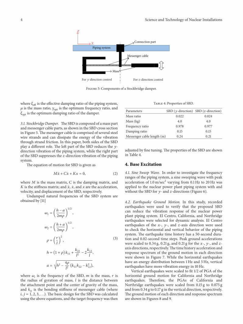
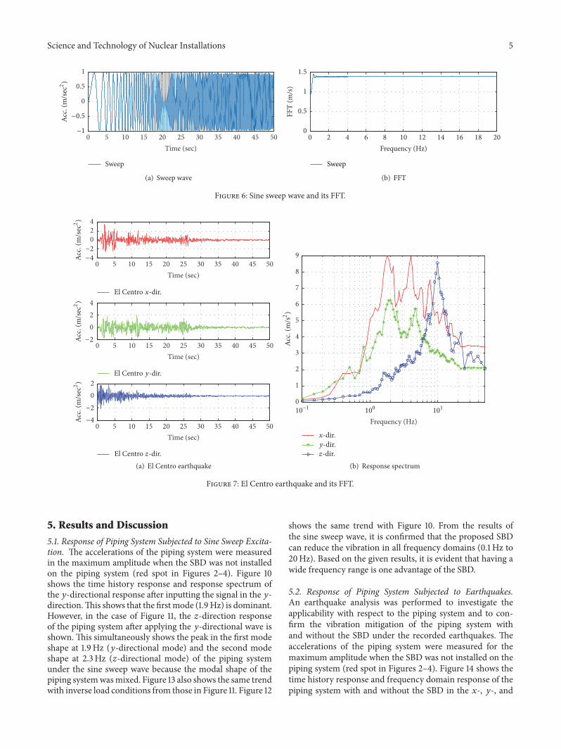
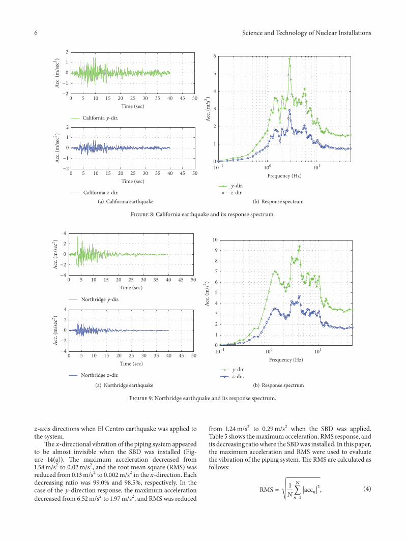
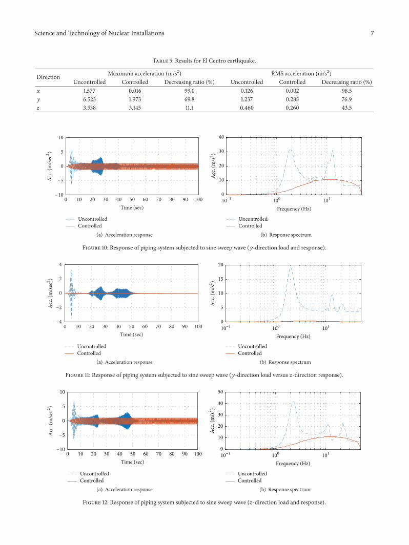
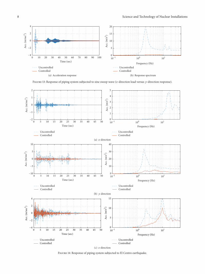
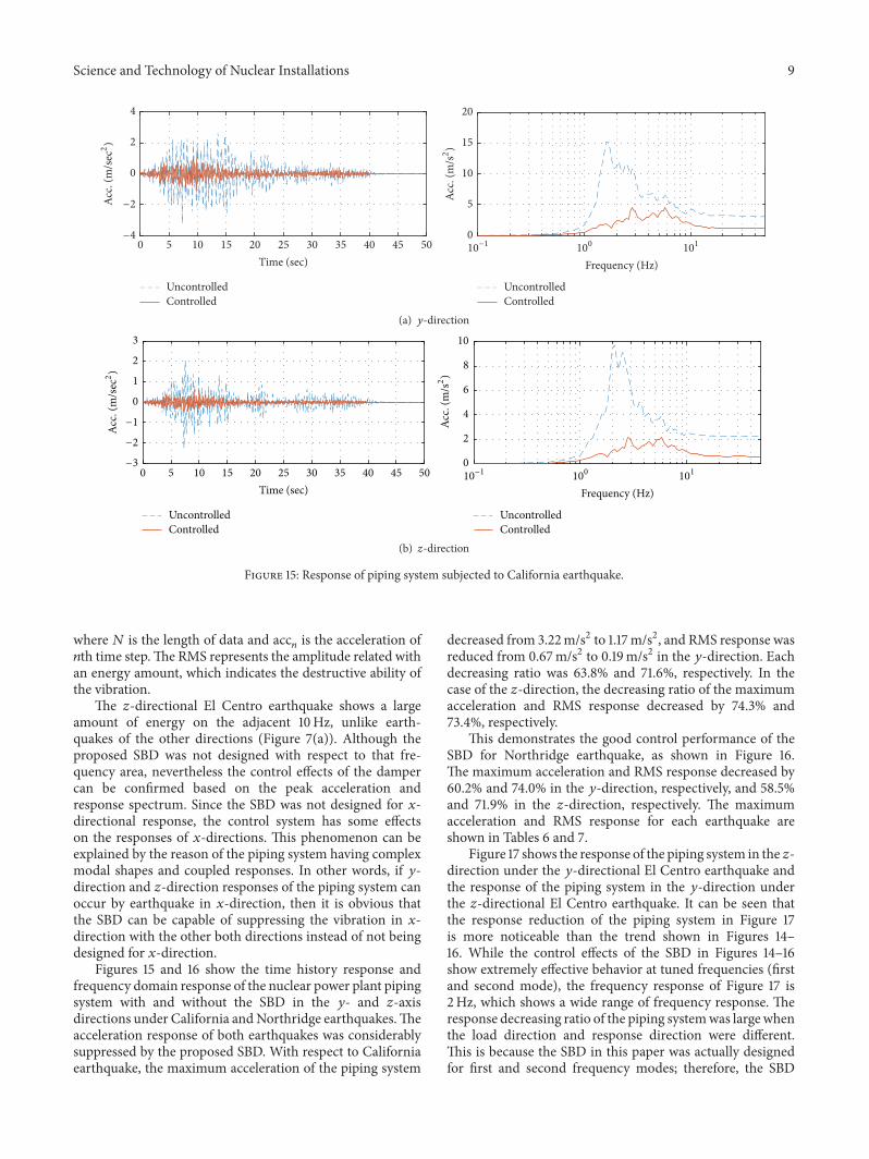
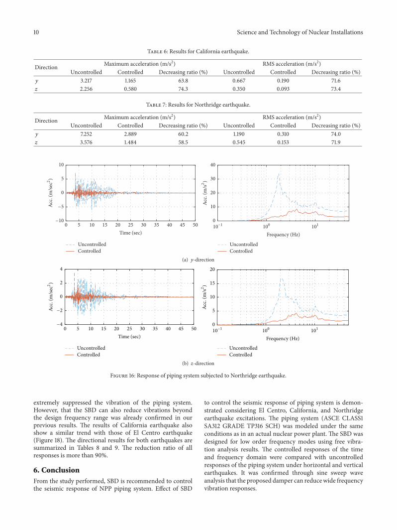
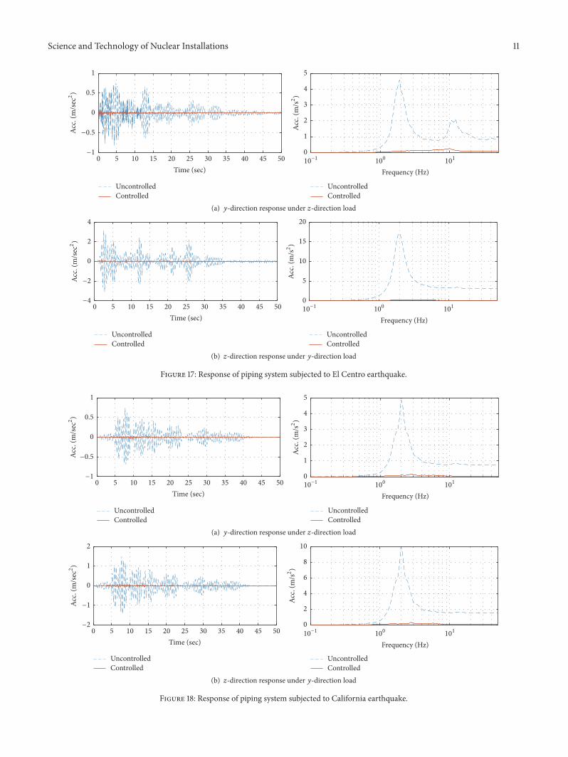
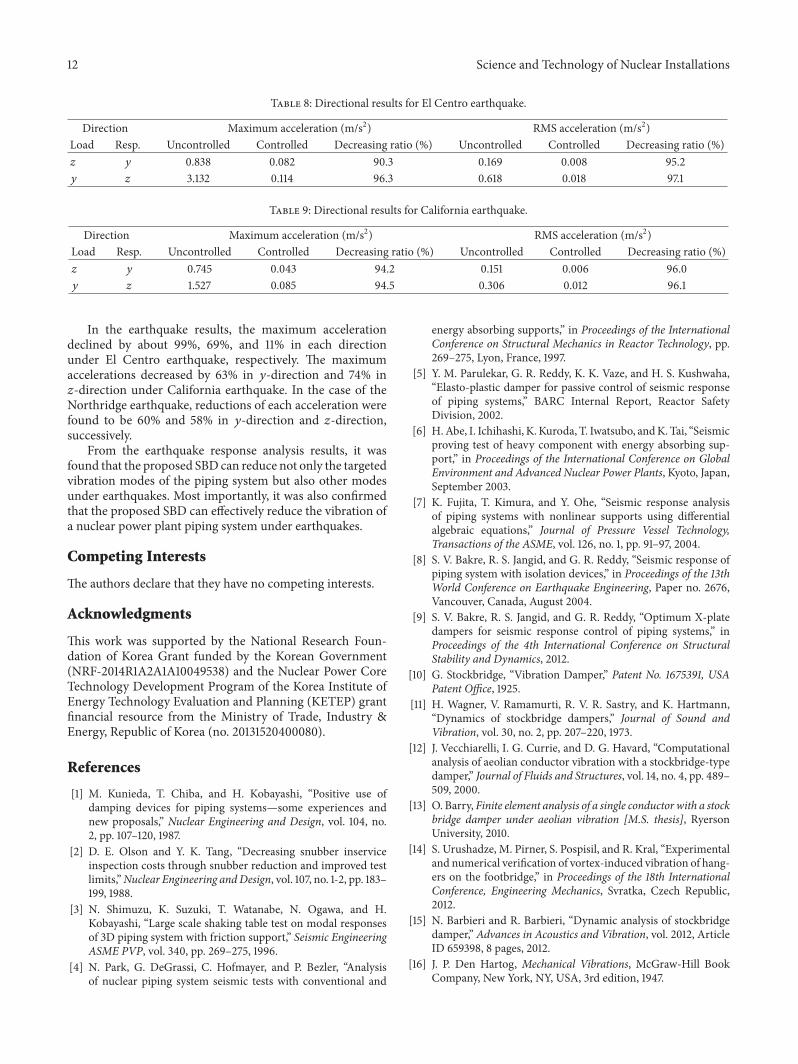