Embed Size (px)
Citation preview
%
#-
cop;’ u 8RM L50122
RESEARCH MEMORANDUM”-
COMPAIUSON OF LARGE -SCALE FLIGHT MEASUREMENTS
OF ZERO-LIFT DRAG AT MACH NUMBERS FROM 0.9 TO 1.7 OF TWO
WING-BODY COMBINATIONS HAVING SIMILAR 60° TRIANGULAR
WINGS WITH NACA
By Eugene
65AO03 SECTIONS
D. Schult
Langley Aeronautical LaboratoryLangley Air Force Base, Ya.
.-
NATIONAL ADVISORY COMM~TEEFOR AERONAUTICS
WASHINGTON
October 25, 19S3
,, ..-, F-. .- --
9
https://ntrs.nasa.gov/search.jsp?R=19930086439 2018-07-16T03:54:44+00:00Z
,..
.
●
.
/2’‘M ssificafhmc~ncelted(IItChafl~ @ /tiLk#J~~’~-@
P& >3..........................*,, ,“:,C,,,: ,:,.M?-JM%‘@&. .fi%w?fk%’’%t:,,.xw
“’ (Oiiiiii MJTHWNZED TO C14AfWE)
... ...
..-.-
-.
By . . . . . . $A&’’%z- ~. . . . . . . . . . . . . . . . . . . . . . . . . . . . . . . . . . . . . . . . . . . . . . . . . . . . . . . . .
t, .,
Gizi=,...............) . . . . . . . . . . . . . . . . . . . . . . . . . . . . . . . . . . . . . . . . . . . . . . . . . . . . . . . . . . . . . . . . . .
GRADE OF OFFICER MAKING CHANGE} f
,,,,,,...~yi?d[d[........ ,..,,,,..............DATE
.
●
.
u
NACA RM L50122
NATIONAL ADVISORY COWTTEE FOR
RESEARCH MEMORANDUM
COMPARISON OF LARGE-SCALE FLIGHT
OF ZERO-LIFT DRAG AT MACH NUKMIRS FROM
AERONAUTICS
EiiE~$“- ‘-:m+375J’ ~=, --
MEASUREMENTS
0.9 TO 1.7 OF Two
WING-B3DY COMBINATIONS HAVING SIMILAR 60° TRIANGULAR
WINGS WITH NACA 65Ao03 SECTIONS
By Eugene D. Schult
SIIMMARY
An investigation of zero-lift drag of a fin-stabilized wing-bodycombination was made at high-subsonic and supersonic speeds in the
Reynolds number range of 13 x 106 to.41 x 106. The ratio of bodyfrontal area to wing area was 0.0612. These data are presented withthose of a wingless body and similar winged body described in NACARM L50D26 in which the ratio of body frontal area to wing area was0.0306. The bodies of both configurations were the ssme as the wing-less body and had parabolic profiles and fineness ratios of 10. Thewings were triangular in plan form with a leading-edge sweep of 60°and NACA 65Ao03 airfoil sections.
The results indicated that the small-winged combination with twofins had a total drag coefficient of 0.01 at subsonic speeds and 0.018to 0.015 at supersonic speeds. Wing-plus-interference drag coefficientvaried from 0.006 at high-subsonic speeds.to 0.01 at transonic speedssmd 0.005 at supersonic speeds.
A comparison of results with a similaq configuration having twicethe wing area indicated that the small-winged body had a greater wing-plus-interference drag coefficient in the subsonic and trsnsonic rangeand approximately equal drag coefficient in the supersonic range. Themutual interference effects were unfavorable for the small-winged con-figuration and favorable for the large-winged confi~ration. The basepressure coefficients for the small-winged body changed from approxi-mately zero at subsonic speeds to -0.075 at supersonic speeds; Doublingthe wing area increased the absolute pressures at the base and corre-spondingly reduced the base drag. This drag, however, represented avery small wrt of the total-drag of the configuration.
2
. —
HACA RM LW122.
INTRODUCTION
●
As part of Its program on transonic research, the Langley PilotlessAircraft Research Division is conducting a series of fr~e-flight testsat high Reynolds numbers to determine the zero-lift drag characteristicsof several winged-body configurations. These tests employ the zmcket-~wered model technique and provide continuous data from supersonic to ,high-subsonic speeds. .-
The yrima~ objective of this series of investigations is to studylow-drag configurations at transonic smd supersonic speeds. A trian-gular wing with NACA 65Ao03 sections was combined with a parabolic bodyof fineness ratio 10. One configuration of this series has already beenflown; it had twice the wing area of the present test model and its
...
results as well as those of a wingless body were reported in reference 1 “..and are included in this paper b determine the effec% of wing sizerelative to the body on the drag characteristics. Previously unpublishedbase-pressure data for the large-winged and wingless models are alsopresented.
The Mach number range forthe Reynolds number based upn
varied from approximately 13 x
CD
cm
c%
mP
q
Y
drag coefficient based
the present test was from 0.9 to 1.7, &d Ua mean aerodynedc chord of 3.42 feet
106 to 41 X“106.●
SYMDLS
on total included wing area
()%-3?body base pressure coefficient, —
q
body base drag coefficient based on body frontal area,
(cm @b&t-~
body base pressure, pounds per square foot
atmospheric pressure, “@unds per square foot
dynamic @essure, pounds per square foot, (71@)
specific-heat ratio, l.ko for air
.-. .—
.
NACA RM L50122 3
M Mach number (V/c)
v model velocity, feet per second
c velocity of sound, feet per second, (49.25 @
T absolute tem~erature, degrees Raikine
% body base area, 0.228 square foot
Sf body frontal area, 0.922 square foot
R Reynolds number based on wing mean aerodymunic chord
?MIDELAND TESTS
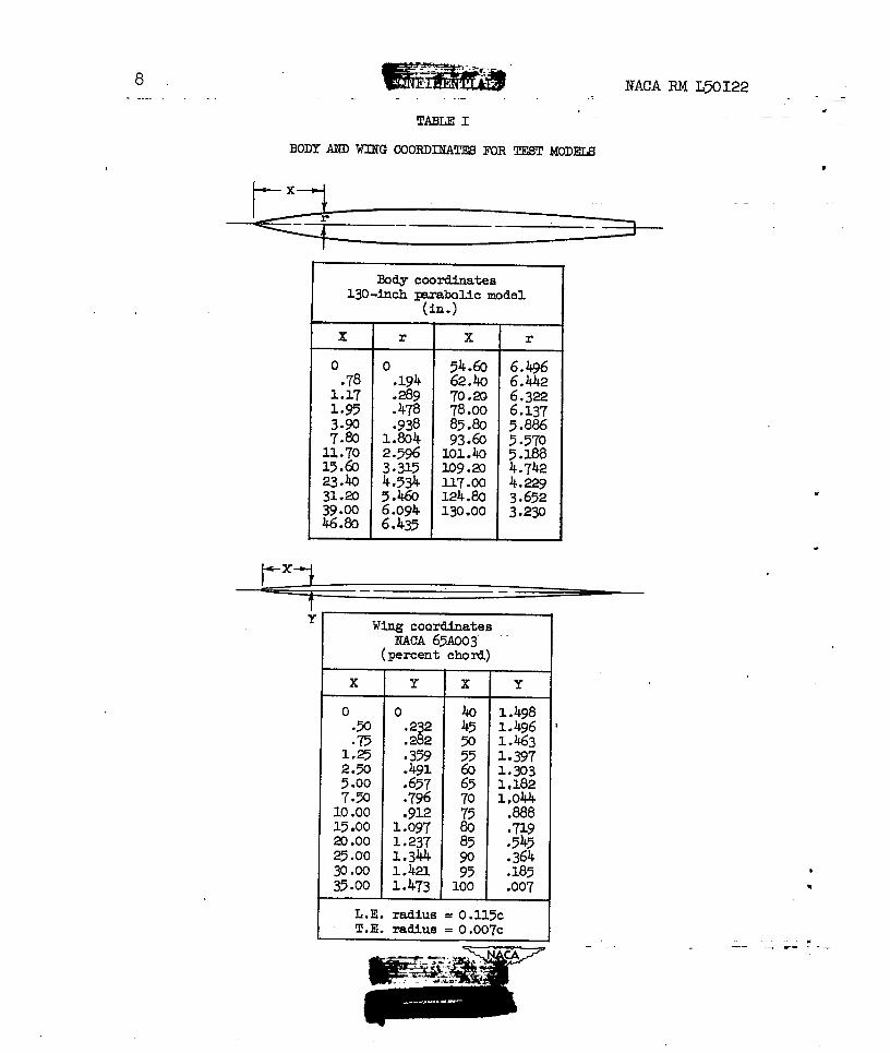
The present test body, the same as that described in reference 1,had a profile formed by parabolic arcs each having its vertex at themsximmn diameter, which was located at the ~-percent body station.The ratio of body length to msximum diameter was 10, the ratio of bodyfrontal area to total included wing area was 0.0612, &nd the ratio ofstern base area to total included wing area was 0.015.
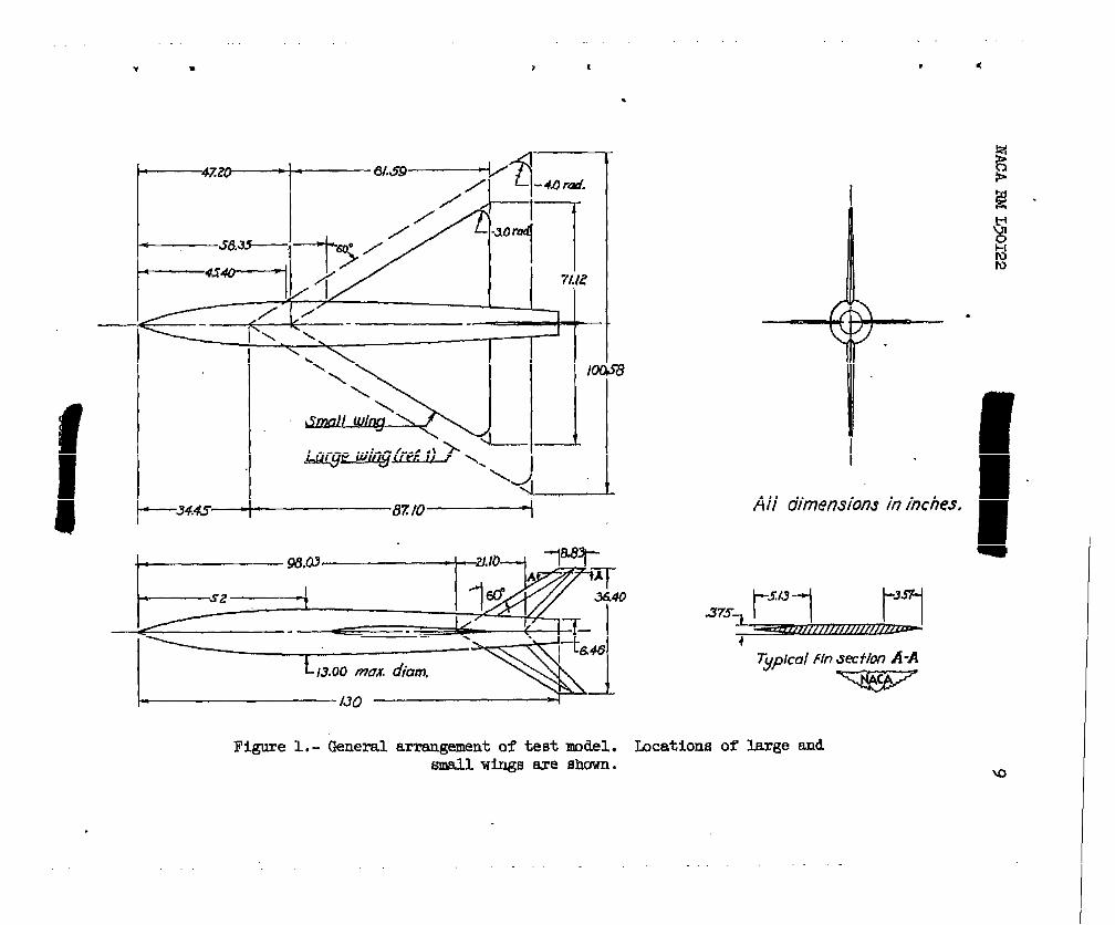
Figure 1 illustrates the general arrangement of the configurationand also shows the larger wing outline from reference 1. The 50-percent-wing-root-chord point was located at body station 78.00 inches for thelarge-winged and small-winged combinations. Station 78.00 correspondsto the 60-percent body station and was selected in this case to maintaina consistency in wing location with other wing ~lan forms tested.
The triangular wing had a leading-edge sweep of 60° and NACA 65AO03airfoil sections parallel to the longitudinal center line of the model.Rounding off the tips for structural reasons resulted in a tatal includedarea of 15.13 square feet or a reduction of approximately 1/2 percentfrom that of the basic triangular plan form. Exposed wing area was10.81 square feet. The correspmling total and exposed areas for thewing reprted in reference 1 were 30.28 and 24.02 square feet, respec-tively. Wing and tidy coordinates are listed in table I.
The two vertical.stabilizing fins were made of magnesium and hadsections as illustrated in figure 1. They were the sszneas those usedon the large-winged body with two fins and on the wingless Imdy withfour fins. A Deacon rocket motor,-rated at a nominal thrust of 5700~unds for 3.5 seconds, propelled the model to its peak velocity.
4,
NACA RM L50122—
wIbppler radar was used to obtain velocity ud acceleration data
which were reduced to drag coefficients by the method described in—
reference 2. A continuous time histo~, of longitudinal accelerationstelemetered to the ground station provided an independent means for
8
substantiating Ik@ler ti~ data. A trajectory was obtained withSCR 584 radar and the necessary atmospheric data from radiosonde obser-
..
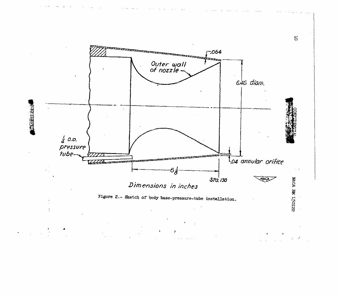
vations. Base pressure coefficients were-derived frqg a survey ofambient pressures and telemetered values of pressure at the baseperiphery. Details of the stern base section are shown in figure 2,
..
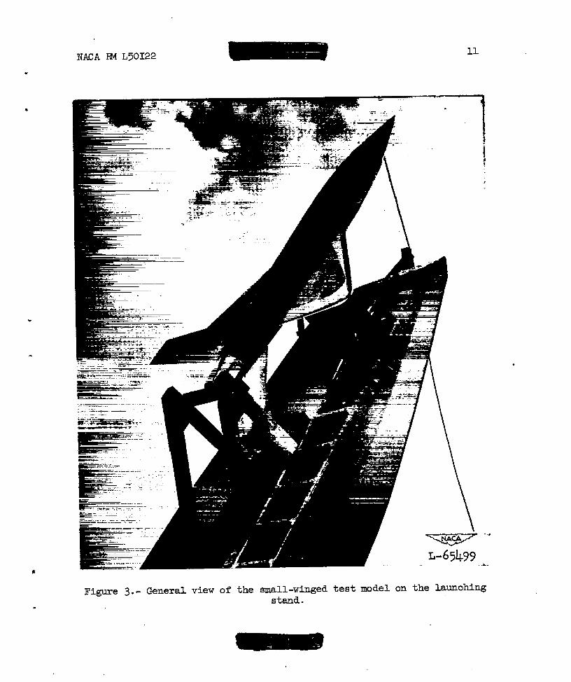
and a general view of the test model on the launching stand is repro-duced in figure 3.
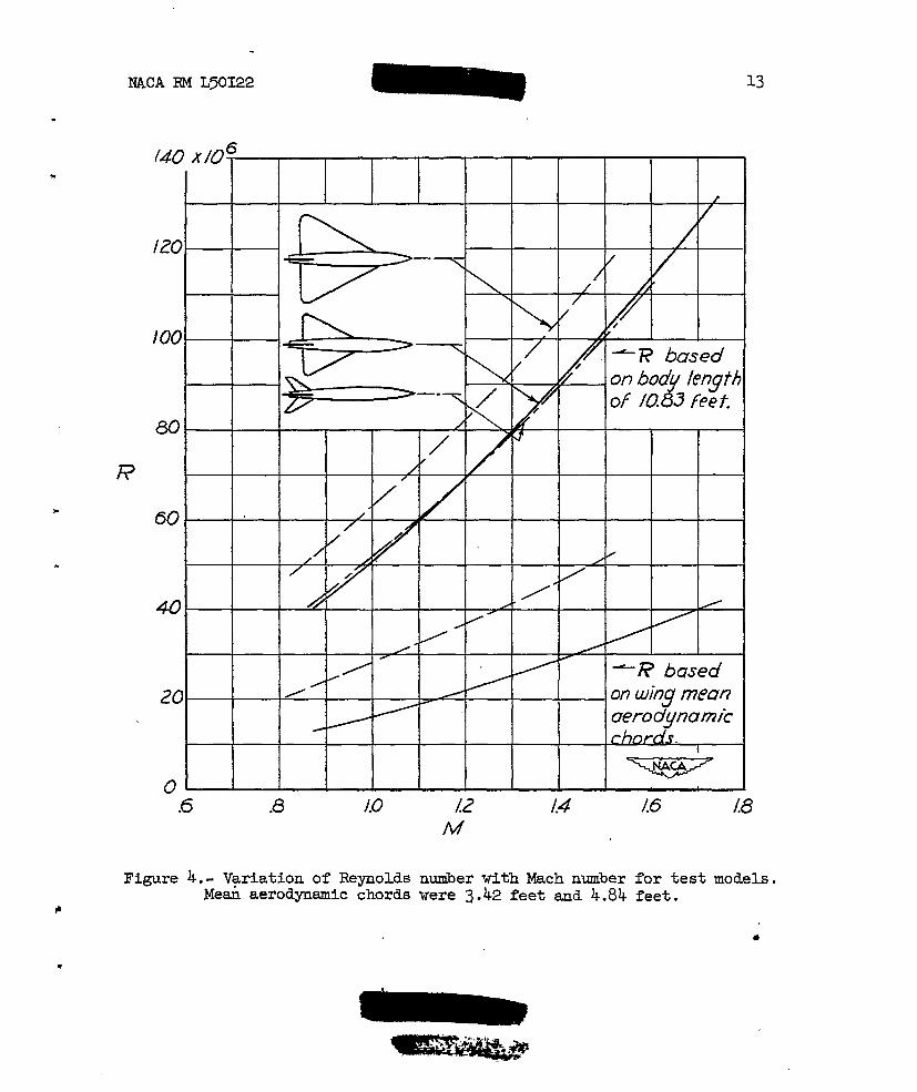
The variation of Reynolds number with Mach nmber is presented infigure 4 for this test configuration andwingless-body configurations reported inbased upn both body length and upon theof the model it represents.
ACCURACY
The accuracy of the test results isfollowing ltits:
for the winged-body andreference 1..:The curves arewing mea aerodynamic chord ..
.
estimated to be within the .
. :
Mach number. . . . . . . . . . . . . . . . . . . . . . . . . m .005 ● .
Total drag coefficient based on wing area of 15.13 sq”’ft . . io.oolo” –
Base pressure coefficients:.
At M=l.3. . . . . . 0 . . . . . . . . . . . . . . . . . io.olAt M=l.O. . . . . . . . . . . . . . . . . . . . . .. . . &()*().2At M =0.9. . . . . . . . . . . . . . . . . . . . . . . . iO.03
Theabsolutebelieved
values listed for drag and base pressure coefficients areaccuracies. Relative values emd trends for tiy one curve areto be more accurate.
RESULTS AND DISCUSSION
Total Drag
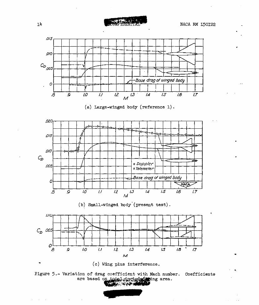
Plots of zero-lift drag coefficients basedarea are presented as a fuuction of Mach number
.
.on total included wingin figures ‘j(a)and
5(b) for the large-winged and the small-winged confi~ations, respec- ● _tively. The drag coefficients for the wingless body have been &&enfrom reference 1 md are shown for com~rison in figures ~(a) and 5(b);
6i?P.Ff!i31i@
NACA RM L’50122 5
9
these data represent the drag of a two-fimed wingless body, based uponthe respective total wing area. Also shown in figures 5(a) and 5(b) arethe variations of base drag coefficient with Mach number for the winged.combinations. The base drag coefficients are referred to the total wingarea of the respective configuration and are derived from values of basepressure measured at the base periphery.
The present test results (fig. 5(b)) show a subsonic drag coeffi-} cient of 0.01 with the force-break Mach number occurring at 0.96; at
supersonic speeds the drag coefficients decreased from 0.0182 at a Machnumber of 1.05 to 0.0152 at a Mach number of 1.75. Slight dips in thedmag curves of the winged bodies near the force-break Mach number wererevealed by continuous-line telemeter records of longitudinal acceler-ations. The cause of these dips smdwhe>her they bear a relationshipto those in base drag is not understood; the Mach number difference of0.01 in this case does not seem to be an error since records of accel-erations and base pressures were recorded simultaneously on the samefilm. ,
Wing-Ilus-hterference Drag
c The wing-plus-interference drag coefficients shown in figure 5(c)were obtained.by subtracting the total drag of the wingless body fromthe total drag of the winged bodies. The wing-plus-interference drag
b coefficients for the small-winged present test configuration areapproximately 0.006 at subsonic and 0.007 at supersonic speeds. Theresults at supersonic speeds agreed closely with those of the larger-winged model and indicate that the coefficients increase only slightlywith area. This analysis, however, does not distinguish between thesmall.differences in base drag, snd a slightly greater spread betweenthe wing-plus-interference curves can be expected at supersonic speedswhen the effect of base drag is taken into account.
At transonic speeds, the over-all drag in ~unds was highest forthe small-winged configuration snd the divergence of the curves islargely the result of a lower drag-rise Mach number of the small-wingedbody with respect to that of either the body alone or the large-wing$dbody . These differences in &g-rise Mach number indicate a criticalinteraction of flows induced by the wing smd body which is favorablefor the larger wing and unfavorable for the smaller wing. An expertientalinvestigation of the effect of location of an retapered 45° swept wingon total drag was re~rted in reference 3, and it was found that a winglocation rearward of maximum body diameter reduced the drag considerably.From the results of the present test, however, it becomes apparent that
● the location of the wing leading edge rearward of the msximum diameteris not sufficient to assure a low over-all drag.
. mmlm
NACA RM L50122
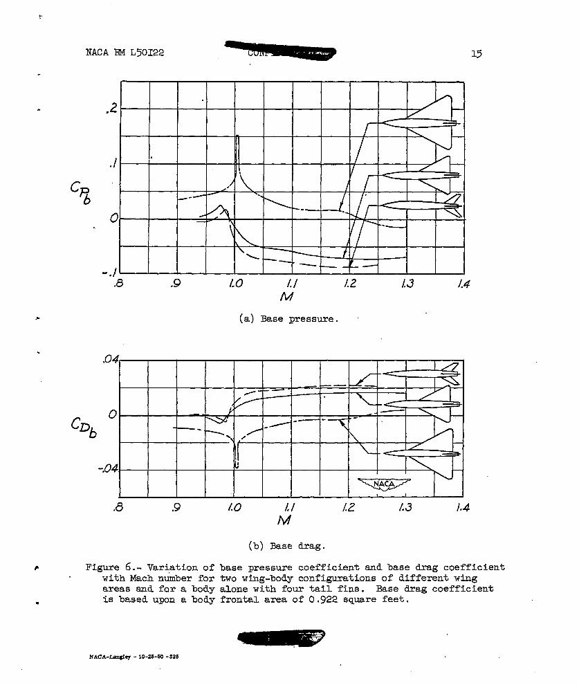
Figure 6(a) presents the variations of base pressure coefficientwith Mach number for the three configurations; these values representa mean of pressures at the base circumference which according &unpublished data are slightly less yositive than coefficients“repre-sentative of the whole base. The differences in the trends of Cw
with Mach number between center and edge orifices were small and forthis test would have little effect on the over-all drag coefficient ofthe combination.
Ease pressure coefficients for the wi~gless body are approximatelyzero near M = 0.95 and change”to approximately -0.08 at supersonicspeeds. The winged bodies had more positive pressure coefficients at_’ ..supersonic speeds than the wingless body with four tall fins by 0.02for the smaller-wingedBody and by 0.10 for the larger-winged bod~.At subsonic speeds the change of base pressure coefficients with body ,configuration was much less. The Reynolds number of the large-wingedbody (fig. 4) was slightly different from that of either the small-winged body or the body alone with four tail fins when Reynolds numbersare based on body length, and the possibility exists that a change inboundary-layer characteristics in the vicinity of the base may haveinfluenced the magnitude of base edge pressures ta some extent.
Ease drag coefficients, referred to body frontal area, are shownin figure 6(b) and are equal to the product of pressure coefficient(fig. 6(a)) and the ratio of base area to frontal area of the body.The base drag at supersonic speeds averaged approximately 10 yercent ,of the total drag of the wingless body, 6 percent of the drag of thesmall-winged configuration, and less than 2 percent for the large-winged configuration.
v
—J
.
CONCLUDINGREMARKS
An investigation of zero-lift drag of R fin-stabilized wing-bodycombination was made &t high-subsonic and supersonic speeds and at”
Reynolds numbers from 13 x 106 to 41 x 106.__The 60° triangular winghad NACA 65AO03 sections and the ratio of body frontal area to wingarea was 0.0612. The body had a parabolic profile and a fineness ratioof 10. The combination was similar to but @d one-half the wing areaof the model described in NACA RM L50D26.
The results indicated that the present small-wing&d configuration ‘- —had a total drag coefficient of 0.01 at subsonic speeds and 0.018 to .-0.015 at supersonic speeds. Wing-plus-interference drag coefficient 9varied from 0.006 at high-subsonic speeds to 0.01 at transonic speeds _and 0.005 at supersonic speeds.
..-. —. -r-.
.
NACA RM L50122 7
A comparison of these results with the lkrge-winged configurationindicated that the small-winged body had a greater wing-plus-interference
# drag coefficient in the subsonic and transonic rsage and approximatelyequal drag coefficient in the supersonic range. At trsnsonic speeds,the small-winged body had greater over-all drag and more unfavorableinterference compared to the larger-winged body:
The base pressure coefficients for the smll-winged body changedfrom approximately zero at subsonic speeds to -0.075 at supersonicspseds. Doubling the wing area increased the absolute yressures at thebase s.ndcorrespondingly reduced the base drag. This drag, however,was a very small part of the total drag of the configuration.
●
Langley Aeronautical LaboratoryNational Advisory Committee for Aeronautics
Lsagley Air Force Ease, Va.
. 1. Nelson, Robert L.: Large-Scale Flight Measurements of Zero-LiftDrag at l&ch Numbers from 0.86 to 1.5 of Wing-E!odyCombinationHating a 60° Triangular Wing with NACA 65Ao03 Sections. NACARM L50D26, 1950.
2. Morrow, John D.: Measure=nts of the Effect of Trailing-EdgeThiclmess on the Zero-Lift Drag of Thin Low-Aspect-Ratio Wings.NACARML50F26, 1950.
3. Mathews, Charles W., and Thompson, Jim Rogers: Comparison of theTransonic Drag Characteristics of Two Wing-Ihdy CombtiationsDiffering Only in the Location of the 45° Sweptback Wing. NACARML7101, 1947.
. .
8 mcA RML50122.
TABLE I
BODY AND WING COORDINATESFOR TEST MODEIS*
l-- x-++
1---4x
Y
E9ay coordinatesIsO-inchwraimlic model
(in.)
x
o.78
1.171.95
?:%11.7015.6023.4031.2039.0046.80
r
o.194.289.478.938
1.8042.5963.3154.5345.4606.0946.435
x
54.6062.ho70.2378.0085.8093.60
101.40109. xl117.00124.80130.00
r
6.4966.A-h26.3226.1375.8865.570:. +::
4:2293.6523.230
—.— —
x
0.50
l:g;:%7.50
10.0015 ●OOa .00?5 .00
$:%
Y
o.2?.2 2
●359.491.657.796.912
1.0971.2371.3441.423.1 ●473
x
$m55
27075&859095
100
7“’Y
1.4981.496 I1.4631.3971.3031,1821,044
.E!I18
-J3;.364.185.007
L.E. radius= 0.115c IT.E. radius= 0.00~c I
---
.
.—.
...=. —- --
-i . s
.
L34.45—
\
i’ n- I
9
All
b-”
dimensions
Figure l.- General arrangementof test model. Locationssmall wings ue shown.
‘Yp’ca’“*Wof large and
—. —
+Ub($’
Figure 2..
. A
-—
6.46 ciiam.
Dh tmwbns in inches
Ske+ch of Imlylxiae-pressue-tube
S?’tl!L30
installation.
.
.
.
NACA m L50122 11
L-65499
-..
.L .
Figure 3.- General view of the small-winged test model on the launohingstsmd.
.
—
.
.
.-
.
NhCA RM L5KX22
.
13
‘+--t+ I---t-’r I I I aerodynamic-
chords.I
-0-.6 .8 /.0
Figure 4.- Variation of ReynoldsMean aerodynamic chords
/2 /.4 16 L8M
number with Mach number for test models.were 3.42 feet and 4.84 feet.
●
.
14 NACA RM L50122
,0/5
.0/0 — — — — ( _ _ : _ _ _ > _ _, :< b——
CD,0031
,% ~
/ “
/ - .
< - b. I
f – Base drag of Wng.sd bodyo .-.
lf— “—
I I.8 .9 LO I.I L? J“ ““14 1$ /.6 AT
(a) Large-winged body (reference 1).
(b) Small-winged body”(present test).
.
●
.
u
s (c) Wing plus interference.
Figure 5.- Variation of drag coef~icient with ~ch number. Coefficientsn.
are based on ng area.
NACA m L50122 15
Cpb
.●2
II
./ s/.
#-- - =..
0 /\
y= ‘—.
\ /L, _ ~ / /
-./— —
.8 .9 Lo L/ /.2 L3 /.4
M
(a) Ike pressure. ~
.8 .9
6 Figure 6.- Variation ofwith Mach n&ber forareas snd for a body
m is based upon a body
Lo L/ /2 /.3 /.4
M
(b) Base drag.
base pressure coefficient and base drag coefficienttwo wing-body configurations of different wingalone with four tail fins. Ease drag coefficientfrontal area of 0.922 square feet.
NACA-Lan@eY - 1O-2S-I5O -325