Embed Size (px)
Citation preview
RESIDENTIAL & LIGHT COMMERCIAL SYSTEMS
2019
Air Conditioning Technologies
1 LG Air Conditioning Technologies
ABOUT LG
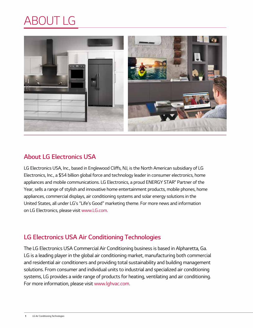
About LG Electronics USA
LG Electronics USA, Inc., based in Englewood Cliffs, NJ, is the North American subsidiary of LG Electronics, Inc., a $54 billion global force and technology leader in consumer electronics, home appliances and mobile communications. LG Electronics, a proud ENERGY STAR® Partner of the Year, sells a range of stylish and innovative home entertainment products, mobile phones, home appliances, commercial displays, air conditioning systems and solar energy solutions in the United States, all under LG’s “Life’s Good” marketing theme. For more news and information on LG Electronics, please visit www.LG.com.
LG Electronics USA Air Conditioning Technologies
The LG Electronics USA Commercial Air Conditioning business is based in Alpharetta, Ga. LG is a leading player in the global air conditioning market, manufacturing both commercial and residential air conditioners and providing total sustainability and building management solutions. From consumer and individual units to industrial and specialized air conditioning systems, LG provides a wide range of products for heating, ventilating and air conditioning. For more information, please visit www.lghvac.com.
2
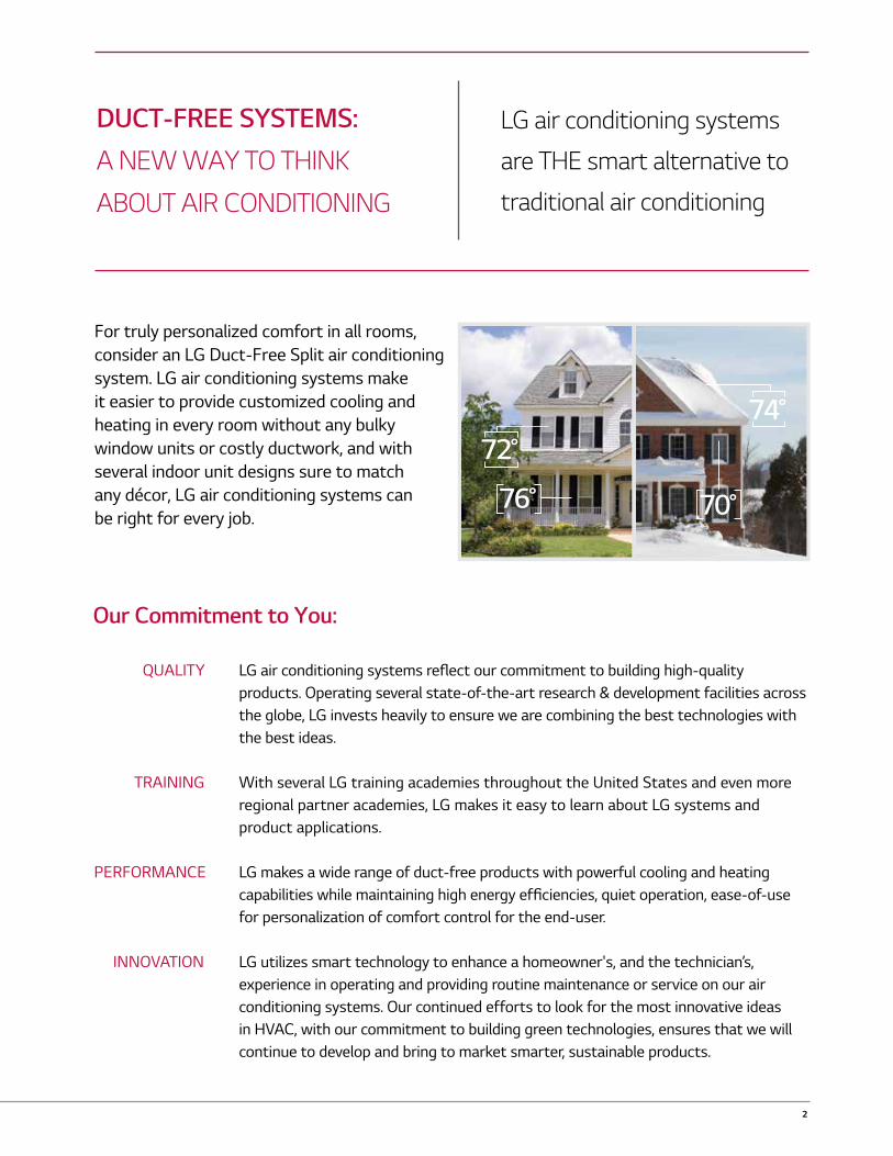
For truly personalized comfort in all rooms, consider an LG Duct-Free Split air conditioning system. LG air conditioning systems make it easier to provide customized cooling and heating in every room without any bulky window units or costly ductwork, and with several indoor unit designs sure to match any décor, LG air conditioning systems can be right for every job.
QUALITY
TRAINING
PERFORMANCE
INNOVATION
LG air conditioning systems reflect our commitment to building high-quality products. Operating several state-of-the-art research & development facilities across the globe, LG invests heavily to ensure we are combining the best technologies with the best ideas.
With several LG training academies throughout the United States and even more regional partner academies, LG makes it easy to learn about LG systems and product applications.
LG makes a wide range of duct-free products with powerful cooling and heating capabilities while maintaining high energy efficiencies, quiet operation, ease-of-use for personalization of comfort control for the end-user.
LG utilizes smart technology to enhance a homeowner's, and the technician’s, experience in operating and providing routine maintenance or service on our air conditioning systems. Our continued efforts to look for the most innovative ideas in HVAC, with our commitment to building green technologies, ensures that we will continue to develop and bring to market smarter, sustainable products.
DUCT-FREE SYSTEMS:A NEW WAY TO THINK
ABOUT AIR CONDITIONING
LG air conditioning systems
are THE smart alternative to
traditional air conditioning
Our Commitment to You:
72°
76°
74°
70°
3 LG Air Conditioning Technologies
4
SINGLE ZONE SYSTEMSWall Mounted
- ART COOL™ Mirror- ART COOL™ Premier- Extended Piping- High Efficiency- Mega 208/230V- Mega 115V
Ceiling Mounted
Low Static Ducted
High Static Ducted
Vertical AHU
111214151616
17
18
19
20
Multi-Zone SYSTEMS
INTRODUCTION
ACCESSORIES
REFERENCE TABLES
Outdoor UnitsIndoor UnitsMulti F MAX Piping AccessoriesMulti F Piping Summary
About LGLG AdvantagesTraining & RecognitionInstallation Best PracticesKey Features
ControlsIndoor AccessoriesOutdoor AccessoriesAir Technologies
23
27
31
32
15789
33
34
35
35
36
38
39
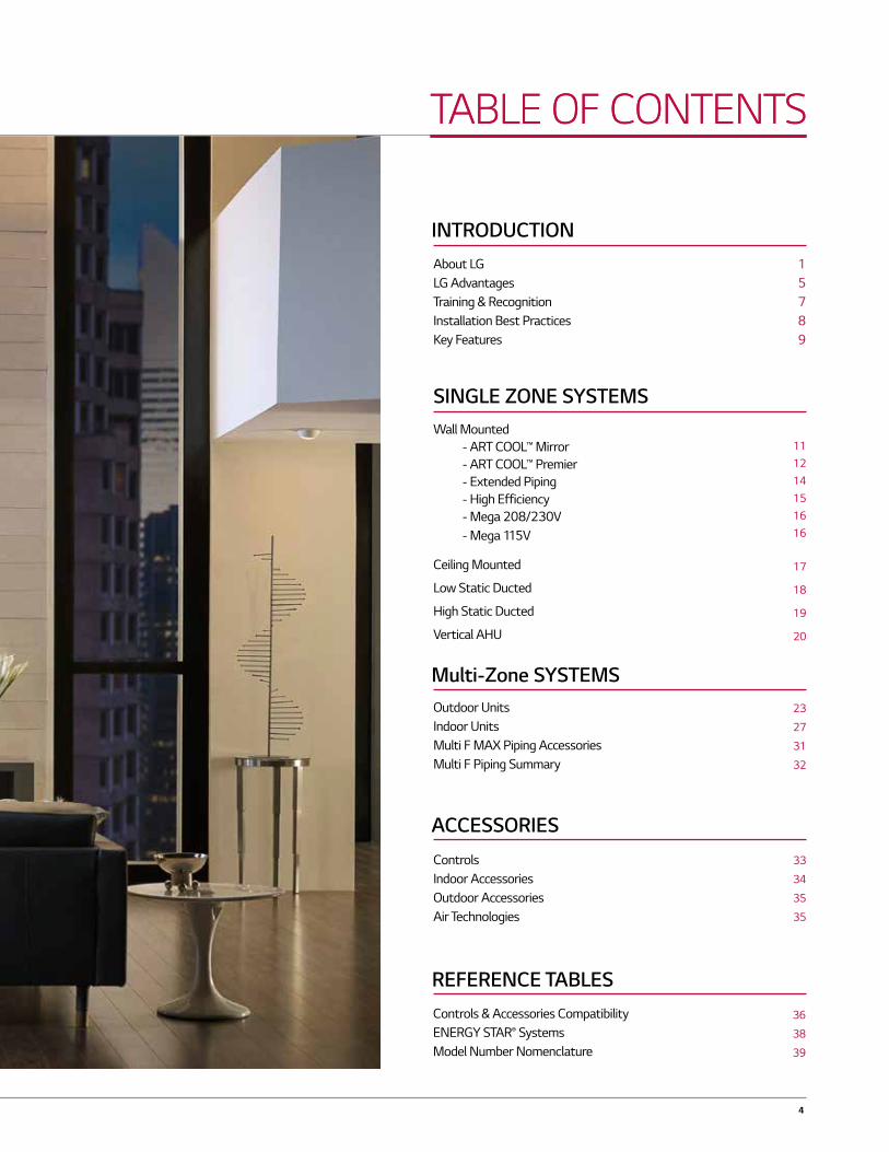
TABLE OF CONTENTS
Controls & Accessories CompatibilityENERGY STAR® SystemsModel Number Nomenclature
TABLE OF CONTENTS
5 LG Air Conditioning Technologies
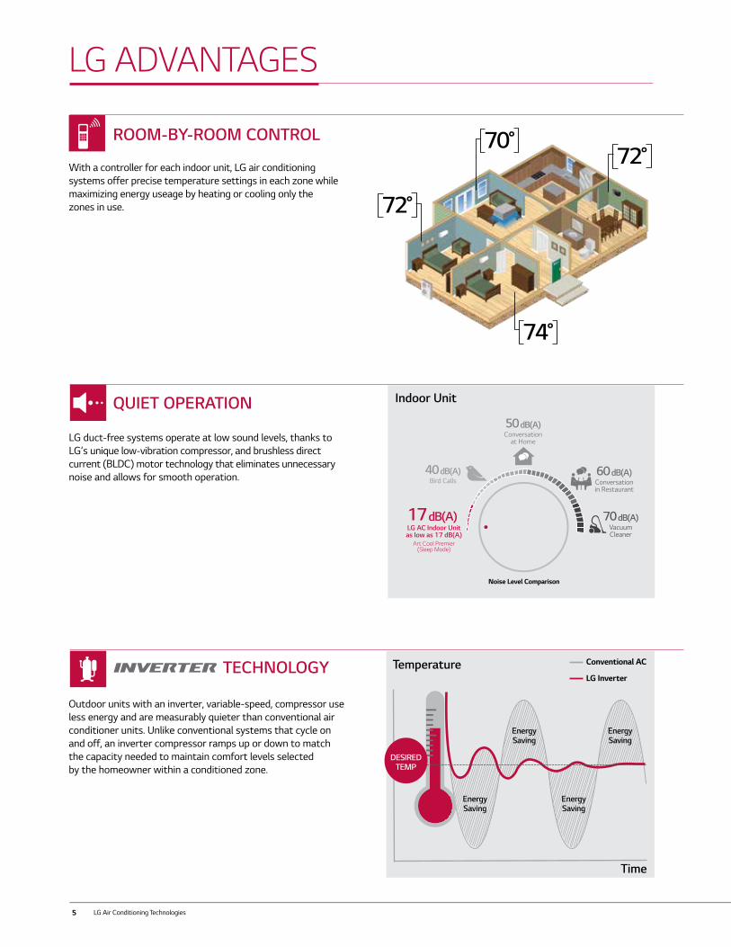
QUIET OPERATION
LG duct-free systems operate at low sound levels, thanks to LG’s unique low-vibration compressor, and brushless direct current (BLDC) motor technology that eliminates unnecessary noise and allows for smooth operation.
19dB
Forest26dB
22dBConventional
Inverter
32dBConventional
On/Off
36dBLibrary
17 dB(A)LG AC Indoor Unit as low as 17 dB(A)
Art Cool Premier (Sleep Mode)
40 dB(A)Bird Calls
50 dB(A)Conversation
at Home
Indoor Unit
60 dB(A)Conversationin Restaurant
70 dB(A)VacuumCleaner
Noise Level Comparison
With a controller for each indoor unit, LG air conditioning systems offer precise temperature settings in each zone while maximizing energy useage by heating or cooling only the zones in use.
ROOM-BY-ROOM CONTROL
TECHNOLOGY
Outdoor units with an inverter, variable-speed, compressor use less energy and are measurably quieter than conventional air conditioner units. Unlike conventional systems that cycle on and off, an inverter compressor ramps up or down to match the capacity needed to maintain comfort levels selected by the homeowner within a conditioned zone.
Energy Saving
Energy Saving
Energy Saving
Energy Saving
DESIREDTEMP
Conventional AC
LG Inverter
70°
72°
74°
72°
LG ADVANTAGES
Temperature
Time
6
Indoor Unit /Evaporator
Conduit for Refrigerant Lines &Wiring
Outdoor Unit / Condenser
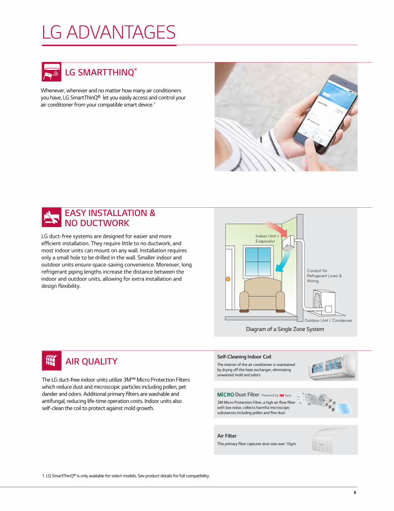
LG SMARTTHINQ®
Whenever, wherever and no matter how many air conditioners you have, LG SmartThinQ® let you easily access and control your air conditioner from your compatible smart device.1
EASY INSTALLATION &NO DUCTWORK
LG duct-free systems are designed for easier and more efficient installation. They require little to no ductwork, and most indoor units can mount on any wall. Installation requires only a small hole to be drilled in the wall. Smaller indoor and outdoor units ensure space-saving convenience. Moreover, long refrigerant piping lengths increase the distance between the indoor and outdoor units, allowing for extra installation and design flexibility.
AIR QUALITY
The LG duct-free indoor units utilize 3M™ Micro Protection Filters which reduce dust and microscopic particles including pollen, pet dander and odors. Additional primary filters are washable and antifungal, reducing life-time operation costs. Indoor units also self-clean the coil to protect against mold growth.
Self-Cleaning Indoor CoilThe interior of the air conditioner is maintained by drying off the heat exchanger, eliminating unwanted mold and odors.
Air FilterThis primary fi lter captures dust size over 10μm.
3M Micro Protection Filter, a high air flow filter with low noise, collects harmful microscopic substances including pollen and fine dust.
Diagram of a Single Zone System
LG ADVANTAGES
1. LG SmartThinQ® is only available for select models. See product details for full compatibility.

7 LG Air Conditioning Technologies
TrainingThe LG US Air Conditioning Technologies division is headquartered near Atlanta in Alpharetta, GA along with a full training academy. Additional training academies are located in California, Texas and New Jersey. Since 2008, our academies have trained thousands on the advantages of LG air conditioning systems, and even more have been trained through LG’s online training modules. Classes are taught by world-class trainers with years of experience in ductless technology with topics that cover everything from design and specification to installation and service.
For HVAC professionals, LG offers online instruction via our Learning Management System and classroom training at our training academies which are placed strategically placed throughout the country. Training is open to all contractors; ask your LG Electronics authorized distributor for details.
For more information and to find out how you can be part of the next training class near you, visit training.lghvac.com
Service ToolsAs part of our commitment to innovation, LG has developed innovative ways to enhance the service technician’s experience during routine maintenance or service with these tools:
• LG SIMS (Smart Inverter Monitoring System) connects to select outdoor units and allows technicians to troubleshoot accurately by interfacing directly with the unit and following step-by-step troubleshooting guidelines. This is a free smartphone app developed by LG factory engineers.
• LG Telepresence connects technicians in the field directly to LG Technical Assistance representatives via a live video feed through the technician’s smartphone, allowing you to bring LG technical support with you to any jobsite.
TAKE YOUR BUSINESS TO NEW LEVELS
The LG Excellence Contractor Program provides specialized support and recognition for contractors who have been trained by factory teams to install LG Residential and Light Commercial Systems, helping to set you apart from your competitors. Along with great incentives and recognition, the LG Excellence Contractor Program provides an enhanced warranty, a website listing with LG Excellence designation on the LG website's contractor locator, consumer lead referrals and local advertising materials. To find out how to put these tools to work for you, visit lghvac.com/excellence
TRAINING & RECOGNITION

8
For jobs small to large, look for opportunities to use LG comfort systems everywhere! Explore the many applications of LG Single and Multi-Zone systems: whole home renovations, older system replacements, home additions, energy savings opportunities, hot or cold zones … and many, many more! System sizing and installation accuracy are key factors for the optimal performanace of a LG comfort system. Increased energy efficiency, customizable design aesthetics and room by room comfort control are just a few of the benefits that come from a properly installed system. Products should be installed in accordance with LG installation manuals and in compliance with applicable state and local codes.
Below are a few of the best practices used by Excellence Contractors across the U.S. during installation:
• Leave appropriate clearances on all sides of the indoor and outdoor units to allow for proper airflow as well as service access• Include space for drainage to ensure condensate flows properly out of the unit• Units should be properly anchored to prevent unnecessary vibrations
Additionally for indoor units:• Keep unit away from any indoor steam or
excessive heat• No obstacles should be placed around unit• Do not install near a doorway or over a window• Condensation drain should be routed away from the indoor unit to the outside
• Use only the correct line sizes as determined by the indoor unit• Use only copper refrigerant piping• Insulate both refrigerant lines independently of each other• Flare connections using a 45-degree flaring tool • Consider Flaretite fittings for all connections and torque flares to specs• Do not exceed the maximum pipe length or install less than the required minimum• Do not make vertical loops in the refrigerant piping• Support pipe runs from sagging or bending
• Quality Flaring Tool
• Digital Refrigerant Charging Scale
• Torque Wrench
• JIS Screwdriver
• Leak test with dry nitrogen to at least 550 p.s.i.• Never use anything but soap bubbles designed for HVAC leak testing• Use only an approved evacuation hose for proper evacuation and leak testing• If possible, remove cores from system prior to starting
evacuation• Start with fresh vacuum pump oil and evacuate to less than 500 microns• If refrigerant is added, use an electronic scale and weigh in the precise amount • Open service valves prior to energizing the unit
• Use wire that fulfills or exceeds the minimum wire requirements:
• Multi F MAX to BD unit: 16-4• All other wiring: 18-4
• L1 and L2 are polarity sensitive on all models• Indoor units are 208/230 volts (or 115 volt on two Mega models)• Terminal 3 is 115 volt• Never use wire nuts or splices in wiring• Use non-insulated spade connectors on all terminal connections• Use a JIS screwdriver on terminal block to avoid stripping out the screws• Only a dedicated electrical circuit is allowed• Always ground indoor and outdoor unit• Only connect one (1) end of the shielded cable if using shielded wire
*NOTE* All wiring must comply with applicable local and national codes.
Unit Placement (Indoor & Outdoor)
Piping Charging
Wiring
• Micron Gauge
• Vacuum Pump
• High-Quality Multimeter
Installation and Service Tools:
INSTALLATION BEST PRACTICES
9 LG Air Conditioning Technologies
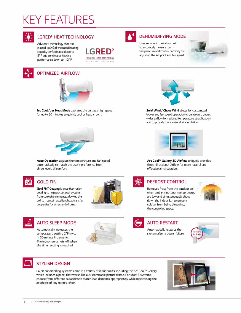
LG air conditioning systems come in a variety of indoor units, including the Art Cool™ Gallery, which includes a panel that works like a customizable picture frame. For Multi F systems, choose from different capacities to match load demands appropriately while maintaining the aesthetic of any room's décor.
STYLISH DESIGN
Uses sensors in the indoor unit to accurately measure room temperature and control humidity by adjusting the set point and fan speed.
DEHUMIDIFYING MODE
KEY FEATURES
Swirl Wind / Chaos Wind allows for customized louver and fan speed operation to create a stronger, wider airflow for reduced temperature stratification and to provide more natural air circulation.
Auto Operation adjusts the temperature and fan speed automatically to match the user’s preference from three levels of comfort.
Art Cool™ Gallery 3D Airflow uniquely provides three-directional airflow for more natural and effective air circulation.
c-4
Automatically increases the temperature setting 2˚F twice in 30 minute increments. The indoor unit shuts off when the timer setting is reached.
AUTO SLEEP MODEAutomatically restarts the system after a power failure.
AUTO RESTART
Restartin 3 min
AutomaticVoltage
Switcher
Jet Cool / Jet Heat Mode operates the unit at a high speed for up to 30 minutes to quickly cool or heat a room.
OPTIMIZED AIRFLOW
Gold Fin™ Coating is an anticorrosion coating to help protect your system from corrosive elements, allowing the coil to maintain excellent heat transfer properties for an extended time.
GOLD FINRemoves frost from the outdoor coil when ambient outdoor temperatures are low and simultaneously shuts down the indoor fan to prevent cold air from being blown into the controlled space.
DEFROST CONTROL
Advanced technology that can exceed 100% of the rated heating capacity performance down to 5° F and continuous heating performance down to -13° F.
LGRED° HEAT TECHNOLOGY
10
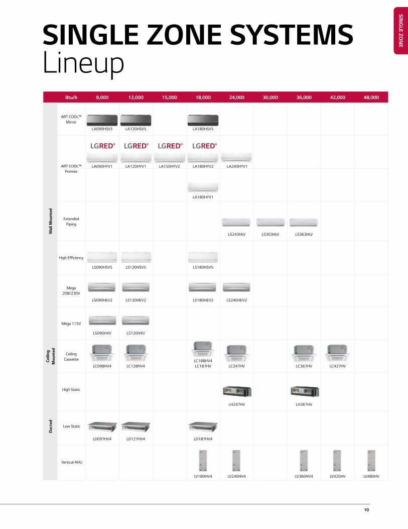
Btu/h 9,000 12,000 15,000 18,000 24,000 30,000 36,000 42,000 48,000
Wal
l Mou
nted
ART COOL™ Mirror
LA090HSV5 LA120HSV5 LA180HSV5
ART COOL™ Premier
LA090HYV1 LA120HYV1 LA150HYV2 LA180HYV2 LA240HYV1
LA180HYV1
Extended Piping
LS243HLV LS303HLV LS363HLV
High Efficiency
LS090HSV5 LS120HSV5 LS180HSV5
Mega 208/230V
LS090HEV2 LS120HEV2 LS180HEV2 LS240HEV2
Mega 115V
LS090HXV LS120HXV
Ceili
ng
Mou
nted
Ceiling Cassette
LC098HV4 LC128HV4
LC188HV4 LC187HV LC247HV LC367HV LC427HV
Duc
ted
High Static
LH247HV LH367HV
Low Static
LD097HV4 LD127HV4 LD187HV4
Vertical AHU
LV180HV4 LV240HV4 LV360HV4 LV420HV LV480HV
SINGLE ZONE SYSTEMSLineup
SING
LE ZON
E

11 LG Air Conditioning Technologies
ART COOL™ MIRRORLA090HSV5LA120HSV5LA180HSV5
Specification Unit LA090HSV5 LA120HSV5 LA180HSV5
Indoor Unit LAN090HSV5 LAN120HSV5 LAN180HSV5
Outdoor Unit LSU090HSV5 LSU120HSV5 LSU180HSV5
Capacity1,2
Rated Cooling Capacity Btu/h 9,000 12,000 18,000
Cooling Capacity Range Btu/h 1,023 ~ 12,625 1,023 ~ 13,785 3,070 ~ 29,515
Rated Heating Capacity Btu/h 10,900 13,600 21,600
Heating Capacity Range Btu/h 1,023 ~ 17,061 1,023 ~ 22,178 3,070 ~ 38,898
Max Heating Capacity at 17°F Btu/h 11,080 13,810 22,340
Max Heating Capacity at 5°F Btu/h 9,570 11,930 19,300
Max Heating Capacity at -4°F Btu/h 8,310 10,360 16,760
SEER, EER Btu/h 23.5, 14.52 22.7, 12.5 21.5, 12.58
HSPF 11.3 11.4 10.2
Power
Voltage (IDU) V- Ø - Hz 208/230-1-60 208/230-1-60 208/230-1-60
Voltage (ODU) V- Ø - Hz 208/230-1-60 208/230-1-60 208/230-1-60
Cooling Power Input kW 0.62 0.96 1.43
Heating Power Input kW 0.71 1.04 1.73
MCA, MOCP A 10, 15 10, 15 13, 20
Power/Communication Wiring3 No. x AWG 4 x 18 4 x 18 4 x 18
Rated Amps (Cool/Heat) A 7.4/7.4 7.4/7.4 9.85/9.85
Operation Range
Heating Operation Range °F WB -4 - 65 -4 - 65 -4 - 65
Cooling Operation Range °F DB 14 - 118 14 - 118 14 - 118
Optional Wind Baffle4 ZLABGP01A (0˚F) ZLABGP01A (0˚F) ZLABGP02A (0˚F)
IDU Operation Range Cooling °F 53 - 75 53 - 75 53 - 75
IDU Operation Range Heating °F 60 - 86 60 - 86 60 - 86
Setpoint Range Cooling °F 64 - 86 64 - 86 64 - 86
Setpoint Range Heating °F 60 - 86 60 - 86 60 - 86
DimensionsIDU Dimensions (WxHxD) in 32-15/16 x 12-1/8 x 7-9/16 32-15/16 x 12-1/8 x 7-9/16 39-9/32 x 13-19/32 x 8-11/32
ODU Dimensions (WxHxD) in 30-5/16 x 21-1/2 x 11-5/16 30-5/16 x 21-1/2 x 11-5/16 34-1/4 x 31-1/2 x 12-19/32
WeightIDU Weight (Net/Shipping) lbs 20.5 / 25.6 20.5 / 25.6 29.8 / 36.4
ODU Weight (Net/Shipping) lbs 74.1 / 78.9 74.1 / 78.9 116.8 / 126.5
Unit Data
Airflow (Max/H/M/L)5 CFM 459 / 338 / 317 / 194 459 / 338 / 317 / 194 706 / 530 / 477 / 371
Dehumidification pts/hr 2.7 2.7 5.5
Compressor Type Twin Rotary Twin Rotary Twin Rotary
Refrigerant Type R410A R410A R410A
Sound Pressure6Indoor (H/M/L/SL) dB(A) 39 / 33 / 23 / 19 39 / 33 / 23 / 19 45 / 40 / 35 / 29
Outdoor Max dB(A) 48 48 53
Piping7
Liquid Pipe in 1/4 1/4 3/8
Vapor Pipe in 3/8 3/8 5/8
Pipe Length (Min/Max) ft 9.8 / 82 9.8 / 82 9.8 / 114.8
Max Pipe Elevation ft 49.2 49.2 49.2
Precharge Pipe Length ft 41 41 24.6
Additional Refrigerant oz/ft 0.22 0.22 0.38
Drain (OD, ID) in 27/32, 5/8 27/32, 5/8 27/32, 5/8
Controller Supplied AKB74955602 AKB74955602 AKB74955602
Note:1. Rated capacity at 0 ft. above sea level with 25 ft. of refrigerant line and a 0 ft. level difference between outdoor and indoor unit.2. Rated cooling capacity obtained with air entering the indoor unit at 80˚F dry bulb (DB) and 67˚F wet bulb (WB) and outdoor ambient conditions of 95˚F dry bulb (DB) and 75˚F wet bulb (WB).
Rated heating capacity obtained with air entering the indoor unit at 70˚F dry bulb (DB) and 60˚F wet bulb (WB) and outdoor ambient conditions of 47˚F dry bulb (DB) and 43˚F wet bulb (WB). For capacity information, see engineering manual capacity tables.
3. All power/communication wiring minimum 4-conductor, stranded, shielded, and must comply with applicable local and national codes.4. Installation of an optional Low Ambient Wind Baffle Kit will allow operation down to 0˚F in cooling mode for applicable outdoor units.5. Airflow shown is in cooling mode.6. Sound pressure levels are tested in an anechoic chamber under ISO Standard 3745 and are the same in both cooling and heating mode. These values can increase due to ambient conditions during operation.7. Piping lengths are equivalent.8. Wi-Fi is not available for LA240HSV39. Due to our commitment to continued innovation, some specifications may be changed without notification.
12
Note:1. Rated capacity at 0 ft. above sea level with 25 ft. of refrigerant line and a 0 ft. level difference between outdoor and indoor unit.2. Rated cooling capacity obtained with air entering the indoor unit at 80˚F dry bulb (DB) and 67˚F wet bulb (WB) and outdoor ambient conditions of 95˚F dry bulb (DB) and 75˚F wet bulb (WB).
Rated heating capacity obtained with air entering the indoor unit at 70˚F dry bulb (DB) and 60˚F wet bulb (WB) and outdoor ambient conditions of 47˚F dry bulb (DB) and 43˚F wet bulb (WB). For capacity information, see engineering manual capacity tables.
3. All power/communication wiring minimum 4-conductor, stranded, shielded, and must comply with applicable local and national codes.4. Installation of an optional Low Ambient Wind Baffle Kit will allow operation down to 0˚F in cooling mode for applicable outdoor units.5. Airflow shown is in cooling mode.6. Sound pressure levels are tested in an anechoic chamber under ISO Standard 3745 and are the same in both cooling and heating mode. These values can increase due to ambient conditions during operation.7. Piping lengths are equivalent.8. Due to our commitment to continued innovation, some specifications may be changed without notification.
SING
LE ZON
E
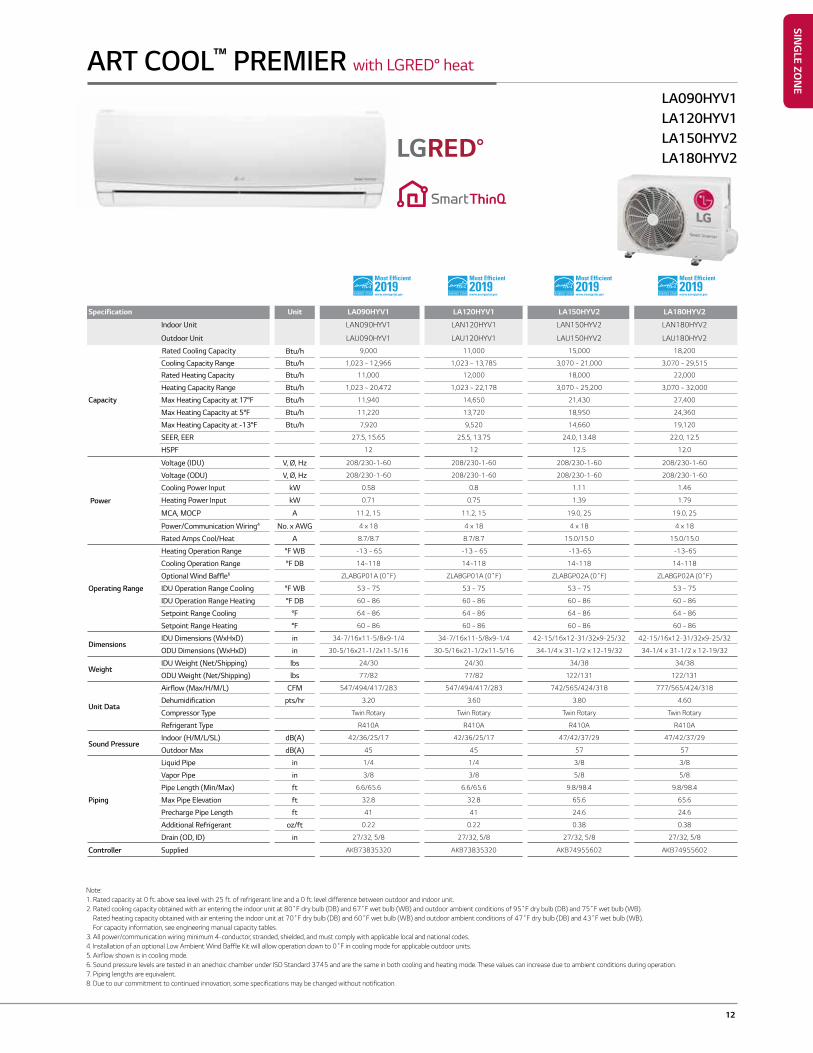
ART COOL™ PREMIER with LGRED° heat
LA090HYV1LA120HYV1LA150HYV2LA180HYV2
Specification Unit LA090HYV1 LA120HYV1 LA150HYV2 LA180HYV2
Indoor Unit LAN090HYV1 LAN120HYV1 LAN150HYV2 LAN180HYV2
Outdoor Unit LAU090HYV1 LAU120HYV1 LAU150HYV2 LAU180HYV2
Rated Cooling Capacity Btu/h 9,000 11,000 15,000 18,200
Cooling Capacity Range Btu/h 1,023 ~ 12,966 1,023 ~ 13,785 3,070 ~ 21,000 3,070 ~ 29,515
Rated Heating Capacity Btu/h 11,000 12,000 18,000 22,000
Heating Capacity Range Btu/h 1,023 ~ 20,472 1,023 ~ 22,178 3,070 ~ 25,200 3,070 ~ 32,000
Capacity Max Heating Capacity at 17°F Btu/h 11,940 14,650 21,430 27,400
Max Heating Capacity at 5°F Btu/h 11,220 13,720 18,950 24,360
Max Heating Capacity at -13°F Btu/h 7,920 9,520 14,660 19,120
SEER, EER 27.5, 15.65 25.5, 13.75 24.0, 13.48 22.0, 12.5
HSPF 12 12 12.5 12.0
Power
Voltage (IDU) V, Ø, Hz 208/230-1-60 208/230-1-60 208/230-1-60 208/230-1-60
Voltage (ODU) V, Ø, Hz 208/230-1-60 208/230-1-60 208/230-1-60 208/230-1-60
Cooling Power Input kW 0.58 0.8 1.11 1.46
Heating Power Input kW 0.71 0.75 1.39 1.79
MCA, MOCP A 11.2, 15 11.2, 15 19.0, 25 19.0, 25
Power/Communication Wiring4 No. x AWG 4 x 18 4 x 18 4 x 18 4 x 18
Rated Amps Cool/Heat A 8.7/8.7 8.7/8.7 15.0/15.0 15.0/15.0
Operating Range
Heating Operation Range °F WB -13 ~ 65 -13 ~ 65 -13~65 -13~65
Cooling Operation Range °F DB 14~118 14~118 14~118 14~118
Optional Wind Baffle6 ZLABGP01A (0˚F) ZLABGP01A (0˚F) ZLABGP02A (0˚F) ZLABGP02A (0˚F)
IDU Operation Range Cooling °F WB 53 ~ 75 53 ~ 75 53 ~ 75 53 ~ 75
IDU Operation Range Heating °F DB 60 ~ 86 60 ~ 86 60 ~ 86 60 ~ 86
Setpoint Range Cooling °F 64 ~ 86 64 ~ 86 64 ~ 86 64 ~ 86
Setpoint Range Heating °F 60 ~ 86 60 ~ 86 60 ~ 86 60 ~ 86
DimensionsIDU Dimensions (WxHxD) in 34-7/16x11-5/8x9-1/4 34-7/16x11-5/8x9-1/4 42-15/16x12-31/32x9-25/32 42-15/16x12-31/32x9-25/32
ODU Dimensions (WxHxD) in 30-5/16x21-1/2x11-5/16 30-5/16x21-1/2x11-5/16 34-1/4 x 31-1/2 x 12-19/32 34-1/4 x 31-1/2 x 12-19/32
WeightIDU Weight (Net/Shipping) lbs 24/30 24/30 34/38 34/38
ODU Weight (Net/Shipping) lbs 77/82 77/82 122/131 122/131
Unit Data
Airflow (Max/H/M/L) CFM 547/494/417/283 547/494/417/283 742/565/424/318 777/565/424/318
Dehumidification pts/hr 3.20 3.60 3.80 4.60
Compressor Type Twin Rotary Twin Rotary Twin Rotary Twin Rotary
Refrigerant Type R410A R410A R410A R410A
Sound PressureIndoor (H/M/L/SL) dB(A) 42/36/25/17 42/36/25/17 47/42/37/29 47/42/37/29
Outdoor Max dB(A) 45 45 57 57
Piping
Liquid Pipe in 1/4 1/4 3/8 3/8
Vapor Pipe in 3/8 3/8 5/8 5/8
Pipe Length (Min/Max) ft 6.6/65.6 6.6/65.6 9.8/98.4 9.8/98.4
Max Pipe Elevation ft 32.8 32.8 65.6 65.6
Precharge Pipe Length ft 41 41 24.6 24.6
Additional Refrigerant oz/ft 0.22 0.22 0.38 0.38
Drain (OD, ID) in 27/32, 5/8 27/32, 5/8 27/32, 5/8 27/32, 5/8
Controller Supplied AKB73835320 AKB73835320 AKB74955602 AKB74955602
13 LG Air Conditioning Technologies
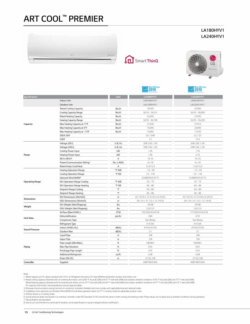
ART COOL™ PREMIERLA180HYV1LA240HYV1
Specification Unit LA180HYV1 LA240HYV1Indoor Unit LAN180HYV1 LAN240HYV1
Outdoor Unit LAU180HYV1 LAU240 HYV1
Capacity
Rated Cooling Capacity Btu/h 18,200 22,000
Cooling Capacity Range Btu/h 3,070 ~ 29,515 3,070 ~ 30,000
Rated Heating Capacity Btu/h 22,000 27,000
Heating Capacity Range Btu/h 3,070 ~ 30,709 3,070 ~ 35,200
Max Heating Capacity at 17°F Btu/h 22,340 27,410
Max Heating Capacity at 5°F Btu/h 19,300 23,690
Max Heating Capacity at -13°F Btu/h 14,060 17,250
SEER, EER 24, 13.48 22, 12.5
HSPF 13 12.3
Power
Voltage (IDU) V, Ø, Hz 208-230, 1, 60 208-230, 1, 60
Voltage (ODU) V, Ø, Hz 208-230, 1, 60 208-230, 1, 60
Cooling Power Input kW 1.35 1.76
Heating Power Input kW 1.69 2.19
MCA, MOCP A 19, 25 19, 25
Power/Communication Wiring3 No. x AWG 4 x 18 4 x 18
Rated Amps Cool/Heat A 15.3/15.3 15.3/15.3
Operating Range
Heating Operation Range °F WB -13 ~ 65 -13 ~ 65
Cooling Operation Range °F DB 14 ~ 118 14 ~ 118
Optional Wind Baffle4 ZLABGP02A (0˚F) ZLABGP02A (0˚F)
IDU Operation Range Cooling °F WB 53 ~ 75 53 ~ 75
IDU Operation Range Heating °F DB 60 ~ 86 60 ~ 86
Setpoint Range Cooling °F 64 ~ 86 64 ~ 86
Setpoint Range Heating °F 60 ~ 86 60 ~ 86
DimensionsIDU Dimensions (WxHxD) in 42-15/16 x 12-31/32 x 9-25/32 42-15/16 x 12-31/32 x 9-25/32
ODU Dimensions (WxHxD) in 34-1/4 × 31-1/2 × 12-19/32 34-1/4 × 31-1/2 × 12-19/32
WeightIDU Weight (Net/Shipping) lbs 34/38 34/38
ODU Weight (Net/Shipping) lbs 122/131 122/131
Unit Data
Airflow (Max/H/M/L) CFM 742/565/424/318 777/565/424/318
Dehumidification pts/hr 3.80 4.70
Compressor Type Twin Rotary Twin Rotary
Refrigerant Type R-410A R-410A
Sound PressureIndoor (H/M/L/SL) dB(A) 47/42/37/29 47/42/37/29
Outdoor Max dB(A) 57 57
Piping
Liquid Pipe in 3/8 3/8
Vapor Pipe in 5/8 5/8
Pipe Length (Min/Max) ft 9.8/98.4 9.8/98.4
Max Pipe Elevation ft 65.6 65.6
Precharge Pipe Length ft 24.6 24.6
Additional Refrigerant oz/ft 0.38 0.38
Drain (OD, ID) in 27/32, 5/8 27/32, 5/8
Controller Supplied AKB74835304 AKB74835304
Note:1. Rated capacity at 0 ft. above sea level with 25 ft. of refrigerant line and a 0 ft. level difference between outdoor and indoor unit.2. Rated cooling capacity obtained with air entering the indoor unit at 80˚F dry bulb (DB) and 67˚F wet bulb (WB) and outdoor ambient conditions of 95˚F dry bulb (DB) and 75˚F wet bulb (WB).
Rated heating capacity obtained with air entering the indoor unit at 70˚F dry bulb (DB) and 60˚F wet bulb (WB) and outdoor ambient conditions of 47˚F dry bulb (DB) and 43˚F wet bulb (WB). For capacity information, see engineering manual capacity tables.
3. All power/communication wiring minimum 4-conductor, stranded, shielded, and must comply with applicable local and national codes.4. Installation of an optional Low Ambient Wind Baffle Kit will allow operation down to 0˚F in cooling mode for applicable outdoor units.5. Airflow shown is in cooling mode.6. Sound pressure levels are tested in an anechoic chamber under ISO Standard 3745 and are the same in both cooling and heating mode. These values can increase due to ambient conditions during operation.7. Piping lengths are equivalent.8. Due to our commitment to continued innovation, some specifications may be changed without notification.
14
SING
LE ZON
E
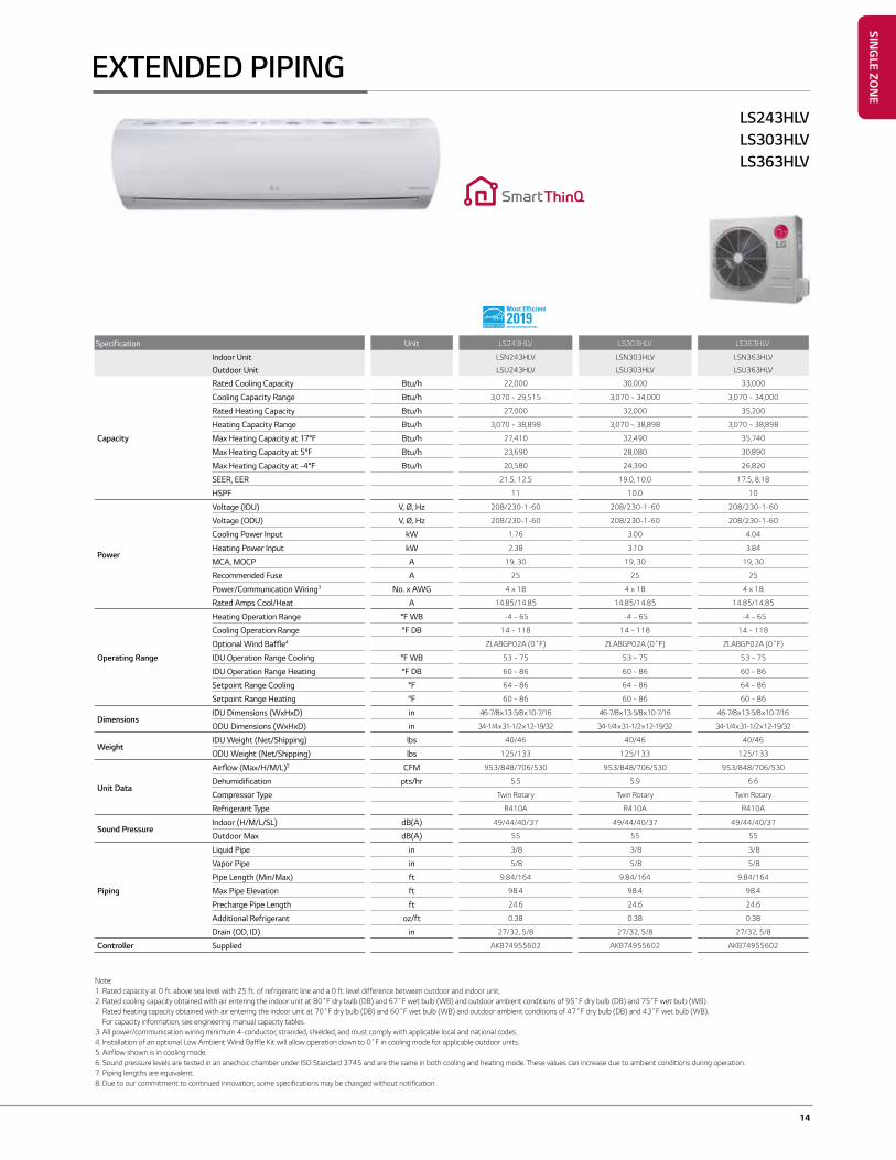
EXTENDED PIPING
Specification Unit LS243HLV LS303HLV LS363HLV
Indoor Unit LSN243HLV LSN303HLV LSN363HLV
Outdoor Unit LSU243HLV LSU303HLV LSU363HLV
Capacity
Rated Cooling Capacity Btu/h 22,000 30,000 33,000
Cooling Capacity Range Btu/h 3,070 ~ 29,515 3,070 ~ 34,000 3,070 ~ 34,000
Rated Heating Capacity Btu/h 27,000 32,000 35,200
Heating Capacity Range Btu/h 3,070 ~ 38,898 3,070 ~ 38,898 3,070 ~ 38,898
Max Heating Capacity at 17°F Btu/h 27,410 32,490 35,740
Max Heating Capacity at 5°F Btu/h 23,690 28,080 30,890
Max Heating Capacity at -4°F Btu/h 20,580 24,390 26,820
SEER, EER 21.5, 12.5 19.0, 10.0 17.5, 8.18
HSPF 11 10.0 10
Power
Voltage (IDU) V, Ø, Hz 208/230-1-60 208/230-1-60 208/230-1-60
Voltage (ODU) V, Ø, Hz 208/230-1-60 208/230-1-60 208/230-1-60
Cooling Power Input kW 1.76 3.00 4.04
Heating Power Input kW 2.38 3.10 3.84
MCA, MOCP A 19, 30 19, 30 19, 30
Recommended Fuse A 25 25 25
Power/Communication Wiring3 No. x AWG 4 x 18 4 x 18 4 x 18
Rated Amps Cool/Heat A 14.85/14.85 14.85/14.85 14.85/14.85
Operating Range
Heating Operation Range °F WB -4 ~ 65 -4 ~ 65 -4 ~ 65
Cooling Operation Range °F DB 14 ~ 118 14 ~ 118 14 ~ 118
Optional Wind Baffle4 ZLABGP02A (0˚F) ZLABGP02A (0˚F) ZLABGP02A (0˚F)
IDU Operation Range Cooling °F WB 53 ~ 75 53 ~ 75 53 ~ 75
IDU Operation Range Heating °F DB 60 ~ 86 60 ~ 86 60 ~ 86
Setpoint Range Cooling °F 64 ~ 86 64 ~ 86 64 ~ 86
Setpoint Range Heating °F 60 ~ 86 60 ~ 86 60 ~ 86
DimensionsIDU Dimensions (WxHxD) in 46-7/8 x 13-5/8 x 10-7/16 46-7/8 x 13-5/8 x 10-7/16 46-7/8 x 13-5/8 x 10-7/16
ODU Dimensions (WxHxD) in 34-1/4 x 31-1/2 x 12-19/32 34-1/4 x 31-1/2 x 12-19/32 34-1/4 x 31-1/2 x 12-19/32
WeightIDU Weight (Net/Shipping) lbs 40/46 40/46 40/46
ODU Weight (Net/Shipping) lbs 125/133 125/133 125/133
Unit Data
Airflow (Max/H/M/L)5 CFM 953/848/706/530 953/848/706/530 953/848/706/530
Dehumidification pts/hr 5.5 5.9 6.6
Compressor Type Twin Rotary Twin Rotary Twin Rotary
Refrigerant Type R410A R410A R410A
Sound PressureIndoor (H/M/L/SL) dB(A) 49/44/40/37 49/44/40/37 49/44/40/37
Outdoor Max dB(A) 55 55 55
Piping
Liquid Pipe in 3/8 3/8 3/8
Vapor Pipe in 5/8 5/8 5/8
Pipe Length (Min/Max) ft 9.84/164 9.84/164 9.84/164
Max Pipe Elevation ft 98.4 98.4 98.4
Precharge Pipe Length ft 24.6 24.6 24.6
Additional Refrigerant oz/ft 0.38 0.38 0.38
Drain (OD, ID) in 27/32, 5/8 27/32, 5/8 27/32, 5/8
Controller Supplied AKB74955602 AKB74955602 AKB74955602
LS243HLVLS303HLVLS363HLV
Note:1. Rated capacity at 0 ft. above sea level with 25 ft. of refrigerant line and a 0 ft. level difference between outdoor and indoor unit.2. Rated cooling capacity obtained with air entering the indoor unit at 80˚F dry bulb (DB) and 67˚F wet bulb (WB) and outdoor ambient conditions of 95˚F dry bulb (DB) and 75˚F wet bulb (WB).
Rated heating capacity obtained with air entering the indoor unit at 70˚F dry bulb (DB) and 60˚F wet bulb (WB) and outdoor ambient conditions of 47˚F dry bulb (DB) and 43˚F wet bulb (WB). For capacity information, see engineering manual capacity tables.
3. All power/communication wiring minimum 4-conductor, stranded, shielded, and must comply with applicable local and national codes.4. Installation of an optional Low Ambient Wind Baffle Kit will allow operation down to 0˚F in cooling mode for applicable outdoor units.5. Airflow shown is in cooling mode.6. Sound pressure levels are tested in an anechoic chamber under ISO Standard 3745 and are the same in both cooling and heating mode. These values can increase due to ambient conditions during operation.7. Piping lengths are equivalent.8. Due to our commitment to continued innovation, some specifications may be changed without notification.
15 LG Air Conditioning Technologies
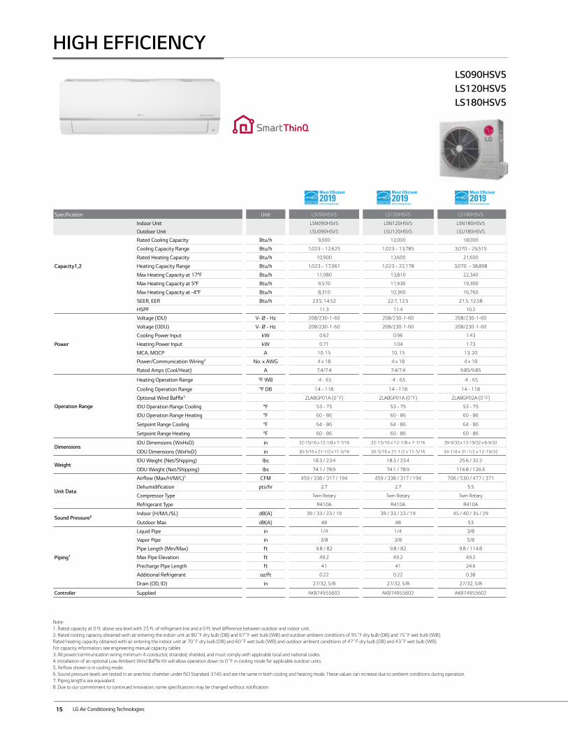
HIGH EFFICIENCY
Specification Unit LS090HSV5 LS120HSV5 LS180HSV5
Indoor Unit LSN090HSV5 LSN120HSV5 LSN180HSV5
Outdoor Unit LSU090HSV5 LSU120HSV5 LSU180HSV5
Capacity1,2
Rated Cooling Capacity Btu/h 9,000 12,000 18,000
Cooling Capacity Range Btu/h 1,023 ~ 12,625 1,023 ~ 13,785 3,070 ~ 29,515
Rated Heating Capacity Btu/h 10,900 13,600 21,600
Heating Capacity Range Btu/h 1,023 ~ 17,061 1,023 ~ 22,178 3,070 ~ 38,898
Max Heating Capacity at 17°F Btu/h 11,080 13,810 22,340
Max Heating Capacity at 5°F Btu/h 9,570 11,930 19,300
Max Heating Capacity at -4°F Btu/h 8,310 10,360 16,760
SEER, EER Btu/h 23.5, 14.52 22.7, 12.5 21.5, 12.58
HSPF 11.3 11.4 10.2
Power
Voltage (IDU) V- Ø - Hz 208/230-1-60 208/230-1-60 208/230-1-60
Voltage (ODU) V- Ø - Hz 208/230-1-60 208/230-1-60 208/230-1-60
Cooling Power Input kW 0.62 0.96 1.43
Heating Power Input kW 0.71 1.04 1.73
MCA, MOCP A 10, 15 10, 15 13, 20
Power/Communication Wiring3 No. x AWG 4 x 18 4 x 18 4 x 18
Rated Amps (Cool/Heat) A 7.4/7.4 7.4/7.4 9.85/9.85
Operation Range
Heating Operation Range °F WB -4 - 65 -4 - 65 -4 - 65
Cooling Operation Range °F DB 14 - 118 14 - 118 14 - 118
Optional Wind Baffle4 ZLABGP01A (0˚F) ZLABGP01A (0˚F) ZLABGP02A (0˚F)
IDU Operation Range Cooling °F 53 - 75 53 - 75 53 - 75
IDU Operation Range Heating °F 60 - 86 60 - 86 60 - 86
Setpoint Range Cooling °F 64 - 86 64 - 86 64 - 86
Setpoint Range Heating °F 60 - 86 60 - 86 60 - 86
DimensionsIDU Dimensions (WxHxD) in 32-15/16 x 12-1/8 x 7-7/16 32-15/16 x 12-1/8 x 7-7/16 39-9/32 x 13-19/32 x 8-9/32
ODU Dimensions (WxHxD) in 30-5/16 x 21-1/2 x 11-5/16 30-5/16 x 21-1/2 x 11-5/16 34-1/4 x 31-1/2 x 12-19/32
WeightIDU Weight (Net/Shipping) lbs 18.3 / 23.4 18.3 / 23.4 25.6 / 32.2
ODU Weight (Net/Shipping) lbs 74.1 / 78.9 74.1 / 78.9 116.8 / 126.5
Unit Data
Airflow (Max/H/M/L)5 CFM 459 / 338 / 317 / 194 459 / 338 / 317 / 194 706 / 530 / 477 / 371
Dehumidification pts/hr 2.7 2.7 5.5
Compressor Type Twin Rotary Twin Rotary Twin Rotary
Refrigerant Type R410A R410A R410A
Sound Pressure6Indoor (H/M/L/SL) dB(A) 39 / 33 / 23 / 19 39 / 33 / 23 / 19 45 / 40 / 35 / 29
Outdoor Max dB(A) 48 48 53
Piping7
Liquid Pipe in 1/4 1/4 3/8
Vapor Pipe in 3/8 3/8 5/8
Pipe Length (Min/Max) ft 9.8 / 82 9.8 / 82 9.8 / 114.8
Max Pipe Elevation ft 49.2 49.2 49.2
Precharge Pipe Length ft 41 41 24.6
Additional Refrigerant oz/ft 0.22 0.22 0.38
Drain (OD, ID) in 27/32, 5/8 27/32, 5/8 27/32, 5/8
Controller Supplied AKB74955602 AKB74955602 AKB74955602
Note:1. Rated capacity at 0 ft. above sea level with 25 ft. of refrigerant line and a 0 ft. level difference between outdoor and indoor unit.2. Rated cooling capacity obtained with air entering the indoor unit at 80˚F dry bulb (DB) and 67˚F wet bulb (WB) and outdoor ambient conditions of 95˚F dry bulb (DB) and 75˚F wet bulb (WB).Rated heating capacity obtained with air entering the indoor unit at 70˚F dry bulb (DB) and 60˚F wet bulb (WB) and outdoor ambient conditions of 47˚F dry bulb (DB) and 43˚F wet bulb (WB).For capacity information, see engineering manual capacity tables.3. All power/communication wiring minimum 4-conductor, stranded, shielded, and must comply with applicable local and national codes.4. Installation of an optional Low Ambient Wind Baffle Kit will allow operation down to 0˚F in cooling mode for applicable outdoor units.5. Airflow shown is in cooling mode.6. Sound pressure levels are tested in an anechoic chamber under ISO Standard 3745 and are the same in both cooling and heating mode. These values can increase due to ambient conditions during operation.7. Piping lengths are equivalent.8. Due to our commitment to continued innovation, some specifications may be changed without notification.
LS090HSV5 LS120HSV5LS180HSV5
16
SING
LE ZON
E
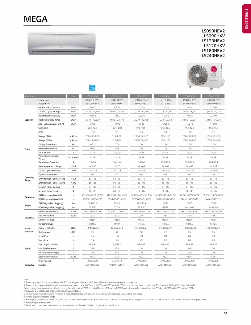
MEGALS090HEV2
LS090HXVLS120HEV2
LS120HXVLS180HEV2LS240HEV2
Specification Unit LS090HEV2 LS090HXV LS120HEV2 LS120HXV LS180HEV2 LS240HEV2
Indoor Unit LSN090HEV2 LSN090HXV LSN120HEV2 LSN120HXV LSN180HEV2 LSN240HEV2
Outdoor Unit LSU090HEV2 LSU090HXV LSU120HEV2 LSU120HXV LSU180HEV2 LSU240HEV2
Capacity
Rated Cooling Capacity Btu/h 9,000 8,500 12,000 12,000 18,000 22,000
Cooling Capacity Range Btu/h 3,070 ~ 10,300 1,023 ~ 13,785 3,070 ~ 13,780 1,023 ~ 13,785 3,685 ~ 18,493 3,685 ~ 24,000
Rated Heating Capacity Btu/h 10,900 10,900 12,000 13,000 19,000 22,000
Heating Capacity Range Btu/h 3,070 ~ 12,520 1,023 ~ 22,178 3,070 ~ 13,780 1,023 ~ 22,178 3,685 ~ 22,997 3,685 ~ 24,226
Max Heating Capacity at 17°F Btu/h 8,760 11,070 9,640 13,200 15,270 17,680
SEER, EER 20.0, 12.5 17.0, 12.01 19.0, 10.51 17.0, 10.5 19.0, 12.0 19.0, 11.0
HSPF 10.0 9.0 9.5 9.0 10.0 9.5
Power
Voltage (IDU) V, Ø, Hz 208/230-1-60 115-1-60 208/230-1-60 115-1-60 208/230-1-60 208/230-1-60
Voltage (ODU) V, Ø, Hz 208/230-1-60 115-1-60 208/230-1-60 115-1-60 208/230-1-60 208/230-1-60
Cooling Power Input kW 0.72 0.71 1.14 1.14 1.50 2.00
Heating Power Input kW 0.88 0.88 1.0 1.09 1.58 1.93
MCA, MOCP A 10, 15 13.5, 20 10, 15 13.5, 20 15, 20 15, 20
Power/Communication Wiring3 No. x AWG 4 x 18 4 x 18 4 x 18 4 x 18 4 x 18 4 x 18
Rated Amps Cool/Heat A 7.4/7.4 10.4/10.4 7.4/7.4 10.4/10.4 10.4/10.4 10.4/10.4
Operating Range
Heating Operation Range °F WB 14 ~ 65 14 ~ 65 14 ~ 65 14 ~ 65 14 ~ 65 14 ~ 65
Cooling Operation Range °F DB 14 ~ 118 14 ~ 118 14 ~ 118 14 ~ 118 14 ~ 118 14 ~ 118
Optional Wind Baffle4 No No No No No No
IDU Operation Range Cooling °F WB 53 ~ 75 53 ~ 75 53 ~ 75 53 ~ 75 53 ~ 75 53 ~ 75
IDU Operation Range Heating °F DB 60 ~ 86 60 ~ 86 60 ~ 86 60 ~ 86 60 ~ 86 60 ~ 86
Setpoint Range Cooling °F 64 ~ 86 64 ~ 86 64 ~ 86 64 ~ 86 64 ~ 86 64 ~ 86
Setpoint Range Heating °F 60 ~ 86 60 ~ 86 60 ~ 86 60 ~ 86 60 ~ 86 60 ~ 86
DimensionsIDU Dimensions (WxHxD) in 32-15/16 x 12-1/8 x 7-7/16 34-27/32 x 11-1/4 x 8-9/32 32-15/16 x 12-1/8 x 7-7/16 34-27/32 x 11-1/4 x 8-9/32 39-9/32 x 13-19/32 x 8-9/32 39-9/32 x 13-19/32 x 8-9/32
ODU Dimensions (WxHxD) in 28-7/32 x 19-1/2 x 9-1/16 28-1/4 x 19-1/2 x 9-1/16 28-7/32x 19-1/2 x 9-1/16 28-1/4 x 19-1/2 x 9-1/16 34-1/4 x 25-19/32 x 13 34-1/4 x 25-19/32 x 13
WeightIDU Weight (Net/Shipping) lbs 19.2/25.4 23/26 19.2/25.4 23/26 26/30 26/30
ODU Weight (Net/Shipping) lbs 55.3/60 67/79 55.3/60 67/79 98.1/108 98.1/108
Unit Data
Airflow (Max/H/M/L) CFM 459/353/264/148 335/272/212/124 459/353/264/148 335/272/212/124 689/512/459/371 689/512/459/371
Dehumidification pts/hr 2.32 2.30 2.75 2.80 3.38 4.86
Compressor Type Rotary Rotary Rotary Rotary Rotary Rotary
Refrigerant Type R410A R410A R410A R410A R410A R410A
Sound Pressure5
Indoor (H/M/L/SL) dB(A) 42/36/28/21 39/33/23/19 42/36/28/21 39/33/23/19 48/43/38/32 48/43/38/32
Outdoor Max dB(A) 50 47 50 47 55 55
Piping6
Liquid Pipe in 1/4 1/4 1/4 1/4 1/4 1/4
Vapor Pipe in 3/8 3/8 3/8 3/8 1/2 1/2
Pipe Length (Min/Max) ft 9.8/49.2 6.6/49.2 9.8/49.2 6.6/49.2 9.8/65.6 9.8/65.6
Max Pipe Elevation ft 23.0 22.9 23.0 22.9 32.8 32.8
Precharge Pipe Length ft 24.6 24.6 24.6 24.6 24.6 24.6
Additional Refrigerant oz/ft 0.22 0.22 0.22 0.22 0.26 0.26
Drain (OD, ID) in 27/32, 5/8 27/32, 5/8 27/32, 5/8 27/32, 5/8 27/32, 5/8 27/32, 5/8
Controller Supplied AKB74955602 AKB73456121 AKB74955602 AKB73456121 AKB74955602 AKB74955602
Note:1. Rated capacity at 0 ft. above sea level with 25 ft. of refrigerant line and a 0 ft. level difference between outdoor and indoor unit.2. Rated cooling capacity obtained with air entering the indoor unit at 80˚F dry bulb (DB) and 67˚F wet bulb (WB) and outdoor ambient conditions of 95˚F dry bulb (DB) and 75˚F wet bulb (WB).Rated heating capacity obtained with air entering the indoor unit at 70˚F dry bulb (DB) and 60˚F wet bulb (WB) and outdoor ambient conditions of 47˚F dry bulb (DB) and 43˚F wet bulb (WB).For capacity information, see engineering manual capacity tables.3. All power/communication wiring minimum 4-conductor, stranded, shielded, and must comply with applicable local and national codes.4. Airflow shown is in cooling mode.5. Sound pressure levels are tested in an anechoic chamber under ISO Standard 3745 and are the same in both cooling and heating mode. These values can increase due to ambient conditions during operation.6. Piping lengths are equivalent.7. Due to our commitment to continued innovation, some specifications may be changed without notification.
17 LG Air Conditioning Technologies
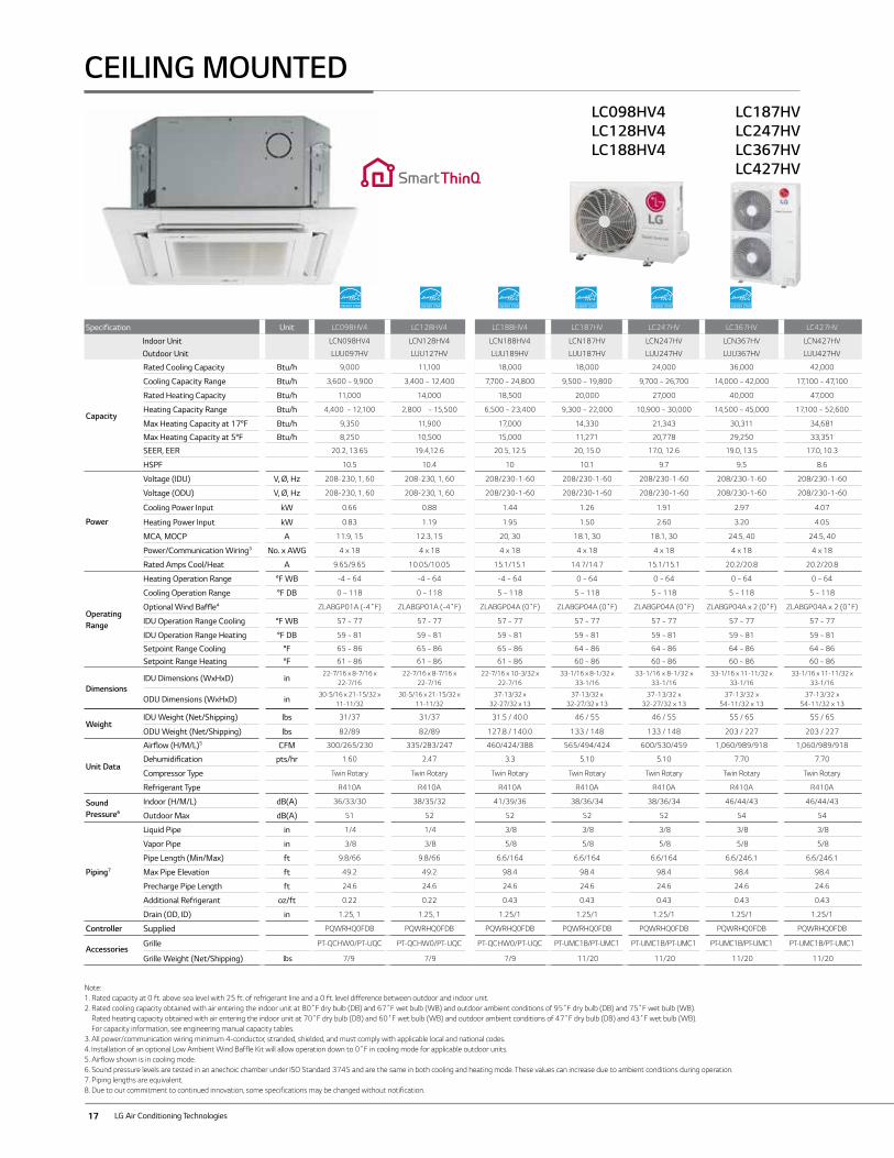
Specification Unit LC098HV4 LC128HV4 LC188HV4 LC187HV LC247HV LC367HV LC427HV
Indoor Unit LCN098HV4 LCN128HV4 LCN188HV4 LCN187HV LCN247HV LCN367HV LCN427HV
Outdoor Unit LUU097HV LUU127HV LUU189HV LUU187HV LUU247HV LUU367HV LUU427HV
Capacity
Rated Cooling Capacity Btu/h 9,000 11,100 18,000 18,000 24,000 36,000 42,000
Cooling Capacity Range Btu/h 3,600 ~ 9,900 3,400 ~ 12,400 7,700 ~ 24,800 9,500 ~ 19,800 9,700 ~ 26,700 14,000 ~ 42,000 17,100 ~ 47,100
Rated Heating Capacity Btu/h 11,000 14,000 18,500 20,000 27,000 40,000 47,000
Heating Capacity Range Btu/h 4,400 ~ 12,100 2,800 ~ 15,500 6,500 ~ 23,400 9,300 ~ 22,000 10,900 ~ 30,000 14,500 ~ 45,000 17,100 ~ 52,600
Max Heating Capacity at 17°F Btu/h 9,350 11,900 17,000 14,330 21,343 30,311 34,681
Max Heating Capacity at 5°F Btu/h 8,250 10,500 15,000 11,271 20,778 29,250 33,351
SEER, EER 20.2, 13.65 19.4,12.6 20.5, 12.5 20, 15.0 17.0, 12.6 19.0, 13.5 17.0, 10.3
HSPF 10.5 10.4 10 10.1 9.7 9.5 8.6
Power
Voltage (IDU) V, Ø, Hz 208-230, 1, 60 208-230, 1, 60 208/230-1-60 208/230-1-60 208/230-1-60 208/230-1-60 208/230-1-60
Voltage (ODU) V, Ø, Hz 208-230, 1, 60 208-230, 1, 60 208/230-1-60 208/230-1-60 208/230-1-60 208/230-1-60 208/230-1-60
Cooling Power Input kW 0.66 0.88 1.44 1.26 1.91 2.97 4.07
Heating Power Input kW 0.83 1.19 1.95 1.50 2.60 3.20 4.05
MCA, MOCP A 11.9, 15 12.3, 15 20, 30 18.1, 30 18.1, 30 24.5, 40 24.5, 40
Power/Communication Wiring3 No. x AWG 4 x 18 4 x 18 4 x 18 4 x 18 4 x 18 4 x 18 4 x 18
Rated Amps Cool/Heat A 9.65/9.65 10.05/10.05 15.1/15.1 14.7/14.7 15.1/15.1 20.2/20.8 20.2/20.8
Operating Range
Heating Operation Range °F WB -4 ~ 64 -4 ~ 64 -4 ~ 64 0 ~ 64 0 ~ 64 0 ~ 64 0 ~ 64
Cooling Operation Range °F DB 0 ~ 118 0 ~ 118 5 ~ 118 5 ~ 118 5 ~ 118 5 ~ 118 5 ~ 118
Optional Wind Baffle4 ZLABGP01A (-4˚F) ZLABGP01A (-4˚F) ZLABGP04A (0˚F) ZLABGP04A (0˚F) ZLABGP04A (0˚F) ZLABGP04A x 2 (0˚F) ZLABGP04A x 2 (0˚F)
IDU Operation Range Cooling °F WB 57 ~ 77 57 - 77 57 ~ 77 57 ~ 77 57 ~ 77 57 ~ 77 57 ~ 77
IDU Operation Range Heating °F DB 59 ~ 81 59 ~ 81 59 ~ 81 59 ~ 81 59 ~ 81 59 ~ 81 59 ~ 81
Setpoint Range Cooling °F 65 ~ 86 65 ~ 86 65 ~ 86 64 ~ 86 64 ~ 86 64 ~ 86 64 ~ 86
Setpoint Range Heating °F 61 ~ 86 61 ~ 86 61 ~ 86 60 ~ 86 60 ~ 86 60 ~ 86 60 ~ 86
DimensionsIDU Dimensions (WxHxD) in
22-7/16 x 8-7/16 x 22-7/16
22-7/16 x 8-7/16 x 22-7/16
22-7/16 x 10-3/32 x 22-7/16
33-1/16 x 8-1/32 x 33-1/16
33-1/16 x 8-1/32 x 33-1/16
33-1/16 x 11-11/32 x 33-1/16
33-1/16 x 11-11/32 x 33-1/16
ODU Dimensions (WxHxD) in30-5/16 x 21-15/32 x
11-11/3230-5/16 x 21-15/32 x
11-11/3237-13/32 x
32-27/32 x 1337-13/32 x
32-27/32 x 1337-13/32 x
32-27/32 x 1337-13/32 x
54-11/32 x 1337-13/32 x
54-11/32 x 13
WeightIDU Weight (Net/Shipping) lbs 31/37 31/37 31.5 / 40.0 46 / 55 46 / 55 55 / 65 55 / 65
ODU Weight (Net/Shipping) lbs 82/89 82/89 127.8 / 140.0 133 / 148 133 / 148 203 / 227 203 / 227
Unit Data
Airflow (H/M/L)5 CFM 300/265/230 335/283/247 460/424/388 565/494/424 600/530/459 1,060/989/918 1,060/989/918
Dehumidification pts/hr 1.60 2.47 3.3 5.10 5.10 7.70 7.70
Compressor Type Twin Rotary Twin Rotary Twin Rotary Twin Rotary Twin Rotary Twin Rotary Twin Rotary
Refrigerant Type R410A R410A R410A R410A R410A R410A R410A
Sound Pressure6
Indoor (H/M/L) dB(A) 36/33/30 38/35/32 41/39/36 38/36/34 38/36/34 46/44/43 46/44/43
Outdoor Max dB(A) 51 52 52 52 52 54 54
Piping7
Liquid Pipe in 1/4 1/4 3/8 3/8 3/8 3/8 3/8
Vapor Pipe in 3/8 3/8 5/8 5/8 5/8 5/8 5/8
Pipe Length (Min/Max) ft 9.8/66 9.8/66 6.6/164 6.6/164 6.6/164 6.6/246.1 6.6/246.1
Max Pipe Elevation ft 49.2 49.2 98.4 98.4 98.4 98.4 98.4
Precharge Pipe Length ft 24.6 24.6 24.6 24.6 24.6 24.6 24.6
Additional Refrigerant oz/ft 0.22 0.22 0.43 0.43 0.43 0.43 0.43
Drain (OD, ID) in 1.25, 1 1.25, 1 1.25/1 1.25/1 1.25/1 1.25/1 1.25/1
Controller Supplied PQWRHQ0FDB PQWRHQ0FDB PQWRHQ0FDB PQWRHQ0FDB PQWRHQ0FDB PQWRHQ0FDB PQWRHQ0FDB
AccessoriesGrille PT-QCHW0/PT-UQC PT-QCHW0/PT-UQC PT-QCHW0/PT-UQC PT-UMC1B/PT-UMC1 PT-UMC1B/PT-UMC1 PT-UMC1B/PT-UMC1 PT-UMC1B/PT-UMC1
Grille Weight (Net/Shipping) lbs 7/9 7/9 7/9 11/20 11/20 11/20 11/20
LC098HV4 LC128HV4 LC188HV4
LC187HV LC247HVLC367HVLC427HV
CEILING MOUNTED
Note:1. Rated capacity at 0 ft. above sea level with 25 ft. of refrigerant line and a 0 ft. level difference between outdoor and indoor unit.2. Rated cooling capacity obtained with air entering the indoor unit at 80˚F dry bulb (DB) and 67˚F wet bulb (WB) and outdoor ambient conditions of 95˚F dry bulb (DB) and 75˚F wet bulb (WB).
Rated heating capacity obtained with air entering the indoor unit at 70˚F dry bulb (DB) and 60˚F wet bulb (WB) and outdoor ambient conditions of 47˚F dry bulb (DB) and 43˚F wet bulb (WB). For capacity information, see engineering manual capacity tables.
3. All power/communication wiring minimum 4-conductor, stranded, shielded, and must comply with applicable local and national codes.4. Installation of an optional Low Ambient Wind Baffle Kit will allow operation down to 0˚F in cooling mode for applicable outdoor units.5. Airflow shown is in cooling mode.6. Sound pressure levels are tested in an anechoic chamber under ISO Standard 3745 and are the same in both cooling and heating mode. These values can increase due to ambient conditions during operation.7. Piping lengths are equivalent.8. Due to our commitment to continued innovation, some specifications may be changed without notification.
18
SING
LE ZON
E
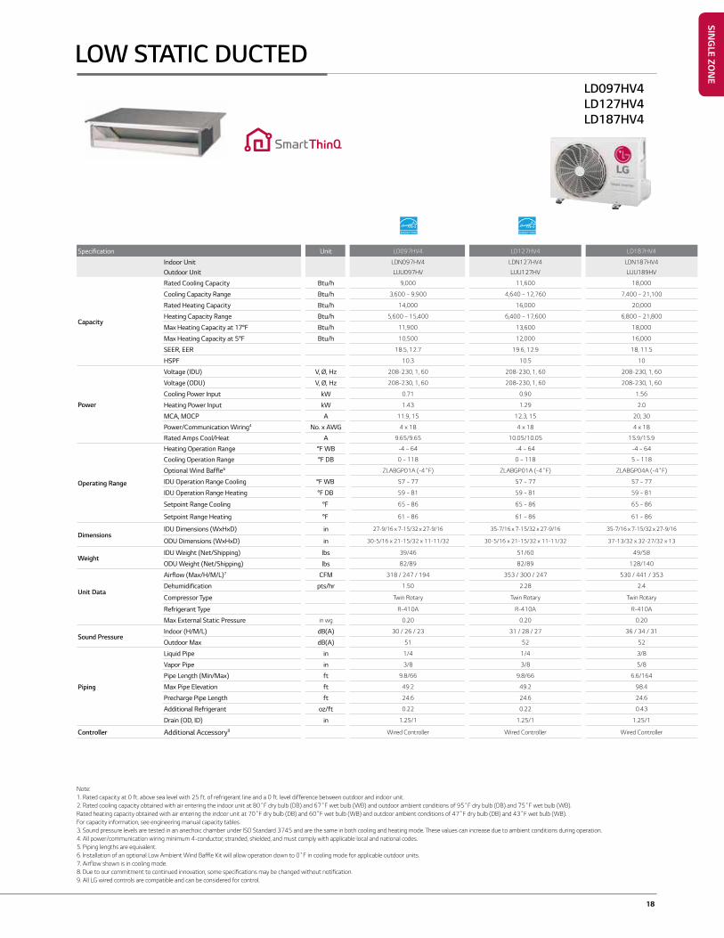
Specification Unit LD097HV4 LD127HV4 LD187HV4
Indoor Unit LDN097HV4 LDN127HV4 LDN187HV4
Outdoor Unit LUU097HV LUU127HV LUU189HV
Capacity
Rated Cooling Capacity Btu/h 9,000 11,600 18,000
Cooling Capacity Range Btu/h 3,600 ~ 9,900 4,640 ~ 12,760 7,400 ~ 21,100
Rated Heating Capacity Btu/h 14,000 16,000 20,000
Heating Capacity Range Btu/h 5,600 ~ 15,400 6,400 ~ 17,600 6,800 ~ 21,800
Max Heating Capacity at 17°F Btu/h 11,900 13,600 18,000
Max Heating Capacity at 5°F Btu/h 10,500 12,000 16,000
SEER, EER 18.5, 12.7 19.6, 12.9 18, 11.5
HSPF 10.3 10.5 10
Power
Voltage (IDU) V, Ø, Hz 208-230, 1, 60 208-230, 1, 60 208-230, 1, 60
Voltage (ODU) V, Ø, Hz 208-230, 1, 60 208-230, 1, 60 208-230, 1, 60
Cooling Power Input kW 0.71 0.90 1.56
Heating Power Input kW 1.43 1.29 2.0
MCA, MOCP A 11.9, 15 12.3, 15 20, 30
Power/Communication Wiring4 No. x AWG 4 x 18 4 x 18 4 x 18
Rated Amps Cool/Heat A 9.65/9.65 10.05/10.05 15.9/15.9
Operating Range
Heating Operation Range °F WB -4 ~ 64 -4 ~ 64 -4 ~ 64
Cooling Operation Range °F DB 0 ~ 118 0 ~ 118 5 ~ 118
Optional Wind Baffle6 ZLABGP01A (-4˚F) ZLABGP01A (-4˚F) ZLABGP04A (-4˚F)
IDU Operation Range Cooling °F WB 57 ~ 77 57 ~ 77 57 ~ 77
IDU Operation Range Heating °F DB 59 ~ 81 59 ~ 81 59 ~ 81
Setpoint Range Cooling °F 65 ~ 86 65 ~ 86 65 ~ 86
Setpoint Range Heating °F 61 ~ 86 61 ~ 86 61 ~ 86
DimensionsIDU Dimensions (WxHxD) in 27-9/16 x 7-15/32 x 27-9/16 35-7/16 x 7-15/32 x 27-9/16 35-7/16 x 7-15/32 x 27-9/16
ODU Dimensions (WxHxD) in 30-5/16 x 21-15/32 x 11-11/32 30-5/16 x 21-15/32 x 11-11/32 37-13/32 x 32-27/32 x 13
WeightIDU Weight (Net/Shipping) lbs 39/46 51/60 49/58
ODU Weight (Net/Shipping) lbs 82/89 82/89 128/140
Unit Data
Airflow (Max/H/M/L)7 CFM 318 / 247 / 194 353 / 300 / 247 530 / 441 / 353
Dehumidification pts/hr 1.50 2.28 2.4
Compressor Type Twin Rotary Twin Rotary Twin Rotary
Refrigerant Type R-410A R-410A R-410A
Max External Static Pressure in wg 0.20 0.20 0.20
Sound PressureIndoor (H/M/L) dB(A) 30 / 26 / 23 31 / 28 / 27 36 / 34 / 31
Outdoor Max dB(A) 51 52 52
Piping
Liquid Pipe in 1/4 1/4 3/8
Vapor Pipe in 3/8 3/8 5/8
Pipe Length (Min/Max) ft 9.8/66 9.8/66 6.6/164
Max Pipe Elevation ft 49.2 49.2 98.4
Precharge Pipe Length ft 24.6 24.6 24.6
Additional Refrigerant oz/ft 0.22 0.22 0.43
Drain (OD, ID) in 1.25/1 1.25/1 1.25/1
Controller Additional Accessory9 Wired Controller Wired Controller Wired Controller
LD097HV4LD127HV4LD187HV4
LOW STATIC DUCTED
Note:1. Rated capacity at 0 ft. above sea level with 25 ft. of refrigerant line and a 0 ft. level difference between outdoor and indoor unit.2. Rated cooling capacity obtained with air entering the indoor unit at 80˚F dry bulb (DB) and 67˚F wet bulb (WB) and outdoor ambient conditions of 95˚F dry bulb (DB) and 75˚F wet bulb (WB).Rated heating capacity obtained with air entering the indoor unit at 70˚F dry bulb (DB) and 60˚F wet bulb (WB) and outdoor ambient conditions of 47˚F dry bulb (DB) and 43˚F wet bulb (WB).For capacity information, see engineering manual capacity tables.3. Sound pressure levels are tested in an anechoic chamber under ISO Standard 3745 and are the same in both cooling and heating mode. These values can increase due to ambient conditions during operation.4. All power/communication wiring minimum 4-conductor, stranded, shielded, and must comply with applicable local and national codes. 5. Piping lengths are equivalent.6. Installation of an optional Low Ambient Wind Baffle Kit will allow operation down to 0˚F in cooling mode for applicable outdoor units.7. Airflow shown is in cooling mode.8. Due to our commitment to continued innovation, some specifications may be changed without notification. 9. All LG wired controls are compatible and can be considered for control.
19 LG Air Conditioning Technologies
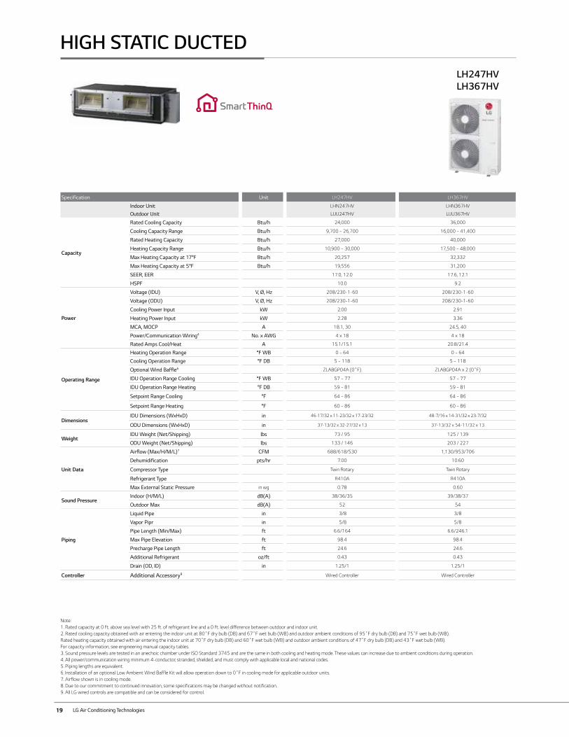
Specification Unit LH247HV LH367HV
Indoor Unit LHN247HV LHN367HV
Outdoor Unit LUU247HV LUU367HV
Capacity
Rated Cooling Capacity Btu/h 24,000 36,000
Cooling Capacity Range Btu/h 9,700 ~ 26,700 16,000 ~ 41,400
Rated Heating Capacity Btu/h 27,000 40,000
Heating Capacity Range Btu/h 10,900 ~ 30,000 17,500 ~ 48,000
Max Heating Capacity at 17°F Btu/h 20,257 32,332
Max Heating Capacity at 5°F Btu/h 19,556 31,200
SEER, EER 17.0, 12.0 17.6, 12.1
HSPF 10.0 9.2
Power
Voltage (IDU) V, Ø, Hz 208/230-1-60 208/230-1-60
Voltage (ODU) V, Ø, Hz 208/230-1-60 208/230-1-60
Cooling Power Input kW 2.00 2.91
Heating Power Input kW 2.28 3.36
MCA, MOCP A 18.1, 30 24.5, 40
Power/Communication Wiring4 No. x AWG 4 x 18 4 x 18
Rated Amps Cool/Heat A 15.1/15.1 20.8/21.4
Operating Range
Heating Operation Range °F WB 0 ~ 64 0 ~ 64
Cooling Operation Range °F DB 5 ~ 118 5 ~ 118
Optional Wind Baffle6 ZLABGP04A (0˚F) ZLABGP04A x 2 (0˚F)
IDU Operation Range Cooling °F WB 57 ~ 77 57 ~ 77
IDU Operation Range Heating °F DB 59 ~ 81 59 ~ 81
Setpoint Range Cooling °F 64 ~ 86 64 ~ 86
Setpoint Range Heating °F 60 ~ 86 60 ~ 86
DimensionsIDU Dimensions (WxHxD) in 46-17/32 x 11-23/32 x 17-23/32 48-7/16 x 14-31/32 x 23-7/32
ODU Dimensions (WxHxD) in 37-13/32 x 32-27/32 x 13 37-13/32 x 54-11/32 x 13
WeightIDU Weight (Net/Shipping) lbs 73 / 95 125 / 139
ODU Weight (Net/Shipping) lbs 133 / 146 203 / 227
Unit Data
Airflow (Max/H/M/L)7 CFM 688/618/530 1,130/953/706
Dehumidification pts/hr 7.00 10.60
Compressor Type Twin Rotary Twin Rotary
Refrigerant Type R410A R410A
Max External Static Pressure in wg 0.78 0.60
Sound PressureIndoor (H/M/L) dB(A) 38/36/35 39/38/37
Outdoor Max dB(A) 52 54
Piping
Liquid Pipe in 3/8 3/8
Vapor Pipr in 5/8 5/8
Pipe Length (Min/Max) ft 6.6/164 6.6/246.1
Max Pipe Elevation ft 98.4 98.4
Precharge Pipe Length ft 24.6 24.6
Additional Refrigerant oz/ft 0.43 0.43
Drain (OD, ID) in 1.25/1 1.25/1
Controller Additional Accessory9 Wired Controller Wired Controller
LH247HVLH367HV
HIGH STATIC DUCTED
Note:1. Rated capacity at 0 ft. above sea level with 25 ft. of refrigerant line and a 0 ft. level difference between outdoor and indoor unit.2. Rated cooling capacity obtained with air entering the indoor unit at 80˚F dry bulb (DB) and 67˚F wet bulb (WB) and outdoor ambient conditions of 95˚F dry bulb (DB) and 75˚F wet bulb (WB).Rated heating capacity obtained with air entering the indoor unit at 70˚F dry bulb (DB) and 60˚F wet bulb (WB) and outdoor ambient conditions of 47˚F dry bulb (DB) and 43˚F wet bulb (WB).For capacity information, see engineering manual capacity tables.3. Sound pressure levels are tested in an anechoic chamber under ISO Standard 3745 and are the same in both cooling and heating mode. These values can increase due to ambient conditions during operation.4. All power/communication wiring minimum 4-conductor, stranded, shielded, and must comply with applicable local and national codes. 5. Piping lengths are equivalent.6. Installation of an optional Low Ambient Wind Baffle Kit will allow operation down to 0˚F in cooling mode for applicable outdoor units.7. Airflow shown is in cooling mode.8. Due to our commitment to continued innovation, some specifications may be changed without notification. 9. All LG wired controls are compatible and can be considered for control.
20
LV360HV4LV420HVLV480HV
Note:1. Rated capacity at 0 ft. above sea level with 25 ft. of refrigerant line and a 0 ft. level difference between outdoor and indoor unit.2. Rated cooling capacity obtained with air entering the indoor unit at 80˚F dry bulb (DB) and 67˚F wet bulb (WB) and outdoor ambient conditions of 95˚F dry bulb (DB) and 75˚F wet bulb (WB).
Rated heating capacity obtained with air entering the indoor unit at 70˚F dry bulb (DB) and 60˚F wet bulb (WB) and outdoor ambient conditions of 47˚F dry bulb (DB) and 43˚F wet bulb (WB). For capacity information, see engineering manual capacity tables.
3. All power/communication wiring minimum 4-conductor, stranded, shielded, and must comply with applicable local and national codes.4. Installation of an optional Low Ambient Wind Baffle Kit will allow operation down to -4˚F in cooling mode for applicable outdoor units.5. Airflow shown is in cooling mode.6. Sound pressure levels are tested in an anechoic chamber under ISO Standard 3745 and are the same in both cooling and heating mode. These values can increase due to ambient conditions during operation.7. Piping lengths are equivalent.8. Due to our commitment to continued innovation, some specifications may be changed without notification. 9. All LG wired controls are compatible and can be considered for control.
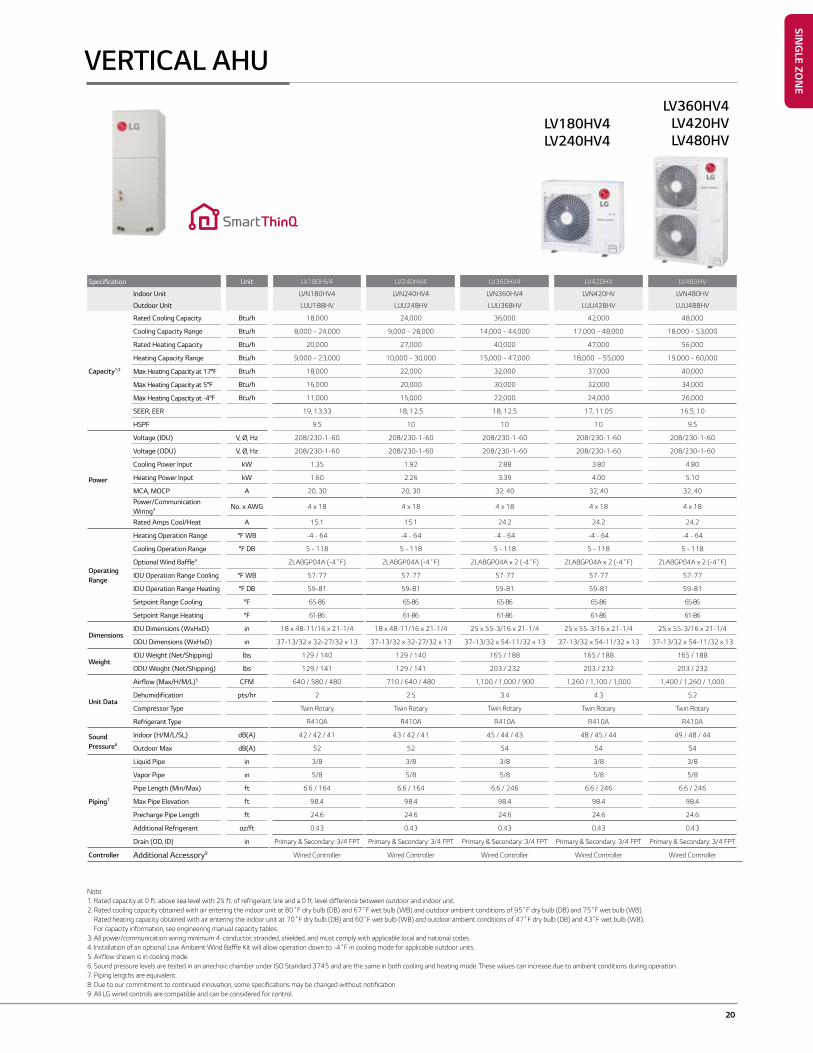
VERTICAL AHU
Specification Unit LV180HV4 LV240HV4 LV360HV4 LV420HV LV480HV
Indoor Unit LVN180HV4 LVN240HV4 LVN360HV4 LVN420HV LVN480HV
Outdoor Unit LUU188HV LUU248HV LUU368HV LUU428HV LUU488HV
Capacity1,2
Rated Cooling Capacity Btu/h 18,000 24,000 36,000 42,000 48,000
Cooling Capacity Range Btu/h 8,000 ~ 24,000 9,000 ~ 28,000 14,000 ~ 44,000 17,000 ~ 48,000 18,000 ~ 53,000
Rated Heating Capacity Btu/h 20,000 27,000 40,000 47,000 56,000
Heating Capacity Range Btu/h 9,000 ~ 23,000 10,000 ~ 30,000 15,000 ~ 47,000 18,000 ~ 55,000 19,000 ~ 60,000
Max Heating Capacity at 17°F Btu/h 18,000 22,000 32,000 37,000 40,000
Max Heating Capacity at 5°F Btu/h 16,000 20,000 30,000 32,000 34,000
Max Heating Capacity at -4°F Btu/h 11,000 15,000 22,000 24,000 26,000
SEER, EER 19, 13.33 18, 12.5 18, 12.5 17, 11.05 16.5, 10
HSPF 9.5 10 10 10 9.5
Power
Voltage (IDU) V, Ø, Hz 208/230-1-60 208/230-1-60 208/230-1-60 208/230-1-60 208/230-1-60
Voltage (ODU) V, Ø, Hz 208/230-1-60 208/230-1-60 208/230-1-60 208/230-1-60 208/230-1-60
Cooling Power Input kW 1.35 1.92 2.88 3.80 4.80
Heating Power Input kW 1.60 2.26 3.39 4.00 5.10
MCA, MOCP A 20, 30 20, 30 32, 40 32, 40 32, 40
Power/Communication Wiring3 No. x AWG 4 x 18 4 x 18 4 x 18 4 x 18 4 x 18
Rated Amps Cool/Heat A 15.1 15.1 24.2 24.2 24.2
Operating Range
Heating Operation Range °F WB -4 - 64 -4 - 64 -4 - 64 -4 - 64 -4 - 64
Cooling Operation Range °F DB 5 - 118 5 - 118 5 - 118 5 - 118 5 - 118
Optional Wind Baffle4 ZLABGP04A (-4˚F) ZLABGP04A (-4˚F) ZLABGP04A x 2 (-4˚F) ZLABGP04A x 2 (-4˚F) ZLABGP04A x 2 (-4˚F)
IDU Operation Range Cooling °F WB 57-77 57-77 57-77 57-77 57-77
IDU Operation Range Heating °F DB 59-81 59-81 59-81 59-81 59-81
Setpoint Range Cooling °F 65-86 65-86 65-86 65-86 65-86
Setpoint Range Heating °F 61-86 61-86 61-86 61-86 61-86
DimensionsIDU Dimensions (WxHxD) in 18 x 48-11/16 x 21-1/4 18 x 48-11/16 x 21-1/4 25 x 55-3/16 x 21-1/4 25 x 55-3/16 x 21-1/4 25 x 55-3/16 x 21-1/4
ODU Dimensions (WxHxD) in 37-13/32 x 32-27/32 x 13 37-13/32 x 32-27/32 x 13 37-13/32 x 54-11/32 x 13 37-13/32 x 54-11/32 x 13 37-13/32 x 54-11/32 x 13
WeightIDU Weight (Net/Shipping) lbs 129 / 140 129 / 140 165 / 188 165 / 188 165 / 188
ODU Weight (Net/Shipping) lbs 129 / 141 129 / 141 203 / 232 203 / 232 203 / 232
Unit Data
Airflow (Max/H/M/L)5 CFM 640 / 580 / 480 710 / 640 / 480 1,100 / 1,000 / 900 1,260 / 1,100 / 1,000 1,400 / 1,260 / 1,000
Dehumidification pts/hr 2 2.5 3.4 4.3 5.2
Compressor Type Twin Rotary Twin Rotary Twin Rotary Twin Rotary Twin Rotary
Refrigerant Type R410A R410A R410A R410A R410A
Sound Pressure6
Indoor (H/M/L/SL) dB(A) 42 / 42 / 41 43 / 42 / 41 45 / 44 / 43 48 / 45 / 44 49 / 48 / 44
Outdoor Max dB(A) 52 52 54 54 54
Piping7
Liquid Pipe in 3/8 3/8 3/8 3/8 3/8
Vapor Pipe in 5/8 5/8 5/8 5/8 5/8
Pipe Length (Min/Max) ft 6.6 / 164 6.6 / 164 6.6 / 246 6.6 / 246 6.6 / 246
Max Pipe Elevation ft 98.4 98.4 98.4 98.4 98.4
Precharge Pipe Length ft 24.6 24.6 24.6 24.6 24.6
Additional Refrigerant oz/ft 0.43 0.43 0.43 0.43 0.43
Drain (OD, ID) in Primary & Secondary: 3/4 FPT Primary & Secondary: 3/4 FPT Primary & Secondary: 3/4 FPT Primary & Secondary: 3/4 FPT Primary & Secondary: 3/4 FPT
Controller Additional Accessory9 Wired Controller Wired Controller Wired Controller Wired Controller Wired Controller
LV180HV4LV240HV4
SING
LE ZON
E
21 LG Air Conditioning Technologies
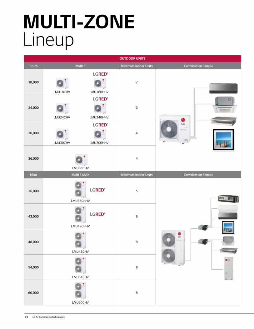
MULTI-ZONELineup
OUTDOOR UNITS
Btu/h Multi F Maximum Indoor Units Combination Sample
18,000
LMU18CHV LMU180HHV
2
24,000
LMU24CHV LMU240HHV
3
30,000
LMU30CHV LMU300HHV
4
36,000
LMU36CHV
4
kBtu Multi F MAX Maximum Indoor Units Combination Sample
36,000
LMU360HHV
5
42,000
LMU420HHV
6
48,000
LMU480HV
8
54,000
LMU540HV
8
60,000
LMU600HV
8
22
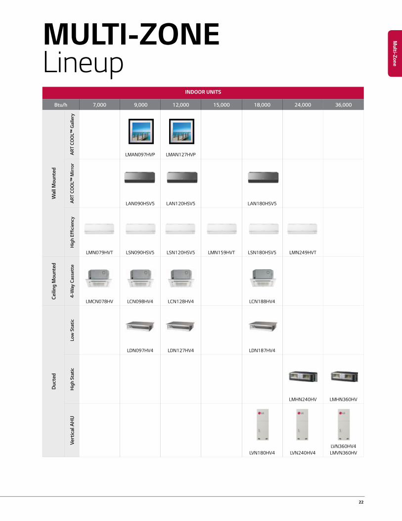
INDOOR UNITS
Btu/h 7,000 9,000 12,000 15,000 18,000 24,000 36,000
Wal
l Mou
nted
ART
CO
OL™
Gal
lery
LMAN097HVP LMAN127HVP
ART
CO
OL™
Mirr
or
LAN090HSV5 LAN120HSV5 LAN180HSV5
Hig
h Ef
ficie
ncy
LMN079HVT LSN090HSV5 LSN120HSV5 LMN159HVT LSN180HSV5 LMN249HVT
Ceili
ng M
ount
ed
4-W
ay C
asse
tte
LMCN078HV LCN098HV4 LCN128HV4 LCN188HV4
Duc
ted
Low
Sta
tic
LDN097HV4 LDN127HV4 LDN187HV4
Hig
h St
atic
LMHN240HV LMHN360HV
Vert
ical
AH
U
LVN180HV4 LVN240HV4LVN360HV4LMVN360HV
MULTI-ZONELineup
Multi-ZoneM
ulti-Zone
23 LG Air Conditioning Technologies
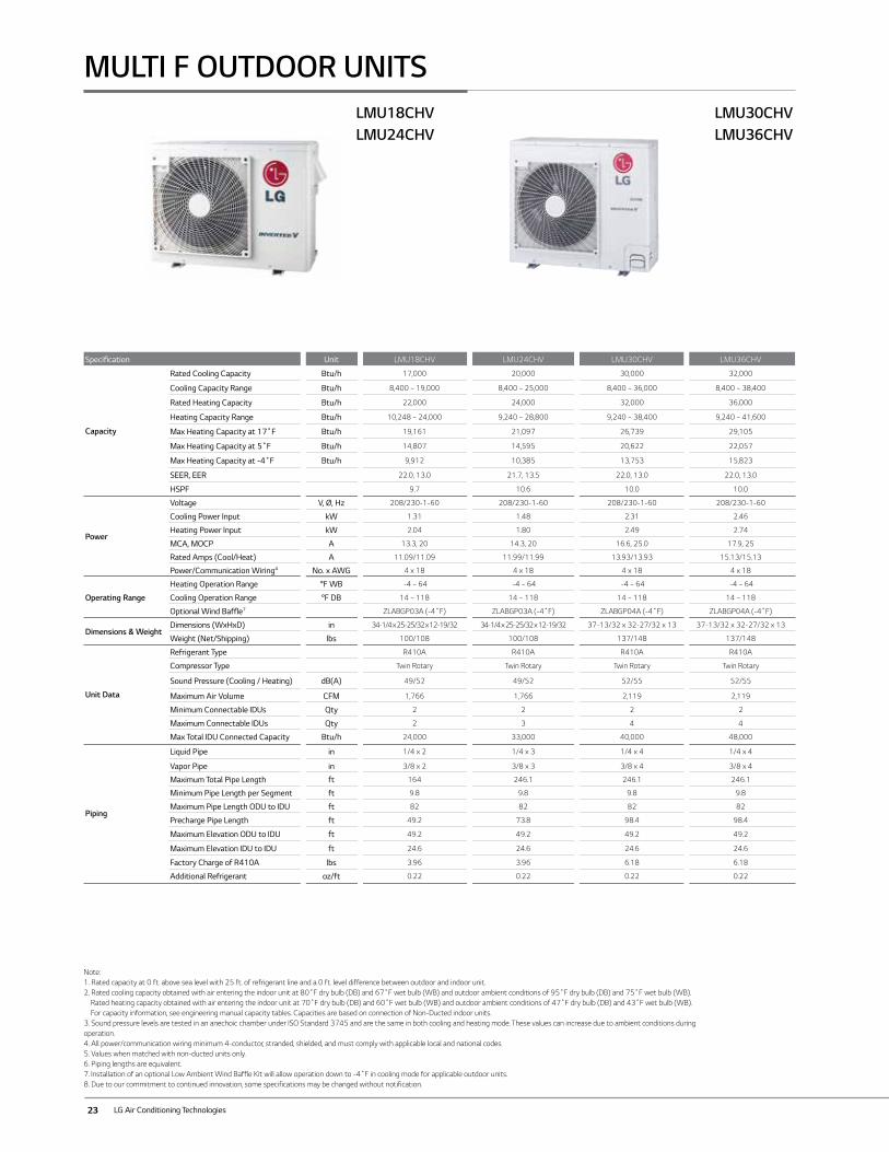
Specification Unit LMU18CHV LMU24CHV LMU30CHV LMU36CHV
Capacity
Rated Cooling Capacity Btu/h 17,000 20,000 30,000 32,000
Cooling Capacity Range Btu/h 8,400 ~ 19,000 8,400 ~ 25,000 8,400 ~ 36,000 8,400 ~ 38,400
Rated Heating Capacity Btu/h 22,000 24,000 32,000 36,000
Heating Capacity Range Btu/h 10,248 ~ 24,000 9,240 ~ 28,800 9,240 ~ 38,400 9,240 ~ 41,600
Max Heating Capacity at 17˚F Btu/h 19,161 21,097 26,739 29,105
Max Heating Capacity at 5˚F Btu/h 14,807 14,595 20,622 22,057
Max Heating Capacity at -4˚F Btu/h 9,912 10,385 13,753 15,823
SEER, EER 22.0, 13.0 21.7, 13.5 22.0, 13.0 22.0, 13.0
HSPF 9.7 10.6 10.0 10.0
Power
Voltage V, Ø, Hz 208/230-1-60 208/230-1-60 208/230-1-60 208/230-1-60
Cooling Power Input kW 1.31 1.48 2.31 2.46
Heating Power Input kW 2.04 1.80 2.49 2.74
MCA, MOCP A 13.3, 20 14.3, 20 16.6, 25.0 17.9, 25
Rated Amps (Cool/Heat) A 11.09/11.09 11.99/11.99 13.93/13.93 15.13/15.13
Power/Communication Wiring4 No. x AWG 4 x 18 4 x 18 4 x 18 4 x 18
Operating Range
Heating Operation Range °F WB -4 ~ 64 -4 ~ 64 -4 ~ 64 -4 ~ 64
Cooling Operation Range °F DB 14 ~ 118 14 ~ 118 14 ~ 118 14 ~ 118
Optional Wind Baffle7 ZLABGP03A (-4˚F) ZLABGP03A (-4˚F) ZLABGP04A (-4˚F) ZLABGP04A (-4˚F)
Dimensions & WeightDimensions (WxHxD) in 34-1/4 x 25-25/32 x 12-19/32 34-1/4 x 25-25/32 x 12-19/32 37-13/32 x 32-27/32 x 13 37-13/32 x 32-27/32 x 13
Weight (Net/Shipping) lbs 100/108 100/108 137/148 137/148
Unit Data
Refrigerant Type R410A R410A R410A R410A
Compressor Type Twin Rotary Twin Rotary Twin Rotary Twin Rotary
Sound Pressure (Cooling / Heating) dB(A) 49/52 49/52 52/55 52/55
Maximum Air Volume CFM 1,766 1,766 2,119 2,119
Minimum Connectable IDUs Qty 2 2 2 2
Maximum Connectable IDUs Qty 2 3 4 4
Max Total IDU Connected Capacity Btu/h 24,000 33,000 40,000 48,000
Piping
Liquid Pipe in 1/4 x 2 1/4 x 3 1/4 x 4 1/4 x 4
Vapor Pipe in 3/8 x 2 3/8 x 3 3/8 x 4 3/8 x 4
Maximum Total Pipe Length ft 164 246.1 246.1 246.1
Minimum Pipe Length per Segment ft 9.8 9.8 9.8 9.8
Maximum Pipe Length ODU to IDU ft 82 82 82 82
Precharge Pipe Length ft 49.2 73.8 98.4 98.4
Maximum Elevation ODU to IDU ft 49.2 49.2 49.2 49.2
Maximum Elevation IDU to IDU ft 24.6 24.6 24.6 24.6
Factory Charge of R410A lbs 3.96 3.96 6.18 6.18
Additional Refrigerant oz/ft 0.22 0.22 0.22 0.22
MULTI F OUTDOOR UNITSLMU30CHVLMU36CHV
LMU18CHV LMU24CHV
Note:1. Rated capacity at 0 ft. above sea level with 25 ft. of refrigerant line and a 0 ft. level difference between outdoor and indoor unit.2. Rated cooling capacity obtained with air entering the indoor unit at 80˚F dry bulb (DB) and 67˚F wet bulb (WB) and outdoor ambient conditions of 95˚F dry bulb (DB) and 75˚F wet bulb (WB). Rated heating capacity obtained with air entering the indoor unit at 70˚F dry bulb (DB) and 60˚F wet bulb (WB) and outdoor ambient conditions of 47˚F dry bulb (DB) and 43˚F wet bulb (WB). For capacity information, see engineering manual capacity tables. Capacities are based on connection of Non-Ducted indoor units.3. Sound pressure levels are tested in an anechoic chamber under ISO Standard 3745 and are the same in both cooling and heating mode. These values can increase due to ambient conditions during operation.4. All power/communication wiring minimum 4-conductor, stranded, shielded, and must comply with applicable local and national codes. 5. Values when matched with non-ducted units only. 6. Piping lengths are equivalent.7. Installation of an optional Low Ambient Wind Baffle Kit will allow operation down to -4˚F in cooling mode for applicable outdoor units.8. Due to our commitment to continued innovation, some specifications may be changed without notification.
24
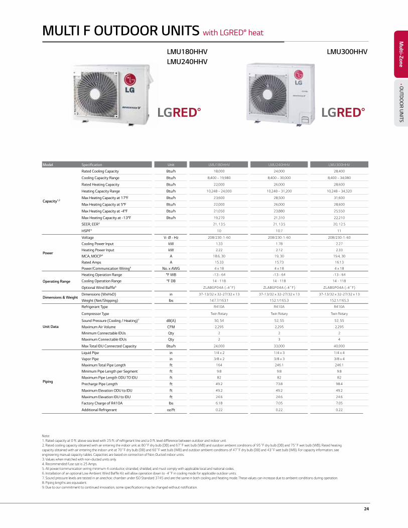
Model Specification Unit LMU180HHV LMU240HHV LMU300HHV
Capacity1,2
Rated Cooling Capacity Btu/h 18,000 24,000 28,400
Cooling Capacity Range Btu/h 8,400 ~ 19,980 8,400 ~ 30,000 8,400 ~ 34,080
Rated Heating Capacity Btu/h 22,000 26,000 28,600
Heating Capacity Range Btu/h 10,248 ~ 24,000 10,248 ~ 31,200 10,248 ~ 34,320
Max Heating Capacity at 17°F Btu/h 23,600 28,500 31,600
Max Heating Capacity at 5°F Btu/h 22,000 26,000 28,600
Max Heating Capacity at -4°F Btu/h 21,050 23,880 25,550
Max Heating Capacity at -13°F Btu/h 19,270 21,310 22,210
SEER, EER3 21, 13.5 21, 13.5 20, 12.5
HSPF3 10 10.7 11
Power
Voltage V- Ø - Hz 208/230-1-60 208/230-1-60 208/230-1-60
Cooling Power Input kW 1.33 1.78 2.27
Heating Power Input kW 2.22 2.12 2.33
MCA, MOCP4 A 18.6, 30 19, 30 19.4, 30
Rated Amps A 15.33 15.73 16.13
Power/Communication Wiring5 No. x AWG 4 x 18 4 x 18 4 x 18
Operating Range
Heating Operation Range °F WB -13 - 64 -13 - 64 -13 - 64
Cooling Operation Range °F DB 14 - 118 14 - 118 14 - 118
Optional Wind Baffle6 ZLABGP04A (-4˚F) ZLABGP04A (-4˚F) ZLABGP04A (-4˚F)
Dimensions & WeightDimensions (WxHxD) in 37-13/32 x 32-27/32 x 13 37-13/32 x 32-27/32 x 13 37-13/32 x 32-27/32 x 13
Weight (Net/Shipping) lbs 147.7/163.1 152.1/165.3 152.1/165.3
Unit Data
Refrigerant Type R410A R410A R410A
Compressor Type Twin Rotary Twin Rotary Twin Rotary
Sound Pressure (Cooling / Heating)7 dB(A) 50, 54 52, 55 52, 55
Maximum Air Volume CFM 2,295 2,295 2,295
Minimum Connectable IDUs Qty 2 2 2
Maximum Connectable IDUs Qty 2 3 4
Max Total IDU Connected Capacity Btu/h 24,000 33,000 40,000
Piping
Liquid Pipe in 1/4 x 2 1/4 x 3 1/4 x 4
Vapor Pipe in 3/8 x 2 3/8 x 3 3/8 x 4
Maximum Total Pipe Length ft 164 246.1 246.1
Minimum Pipe Length per Segment ft 9.8 9.8 9.8
Maximum Pipe Length ODU TO IDU ft 82 82 82
Precharge Pipe Length ft 49.2 73.8 98.4
Maximum Elevation ODU to IDU ft 49.2 49.2 49.2
Maximum Elevation IDU to IDU ft 24.6 24.6 24.6
Factory Charge of R410A lbs 6.18 7.05 7.05
Additional Refrigerant oz/ft 0.22 0.22 0.22
MULTI F OUTDOOR UNITS with LGRED° heat
LMU300HHV
Note:1. Rated capacity at 0 ft. above sea level with 25 ft. of refrigerant line and a 0 ft. level difference between outdoor and indoor unit. 2. Rated cooling capacity obtained with air entering the indoor unit at 80˚F dry bulb (DB) and 67˚F wet bulb (WB) and outdoor ambient conditions of 95˚F dry bulb (DB) and 75˚F wet bulb (WB). Rated heating capacity obtained with air entering the indoor unit at 70˚F dry bulb (DB) and 60˚F wet bulb (WB) and outdoor ambient conditions of 47˚F dry bulb (DB) and 43˚F wet bulb (WB). For capacity information, see engineering manual capacity tables. Capacities are based on connection of Non-Ducted indoor units. 3. Values when matched with non-ducted units only.4. Recommended fuse sze is 25 Amps.5. All power/communication wiring minimum 4-conductor, stranded, shielded, and must comply with applicable local and national codes. 6. Installation of an optional Low Ambient Wind Baffle Kit will allow operation down to -4˚F in cooling mode for applicable outdoor units. 7. Sound pressure levels are tested in an anechoic chamber under ISO Standard 3745 and are the same in both cooling and heating mode. These values can increase due to ambient conditions during operation. 8. Piping lengths are equivalent. 9. Due to our commitment to continued innovation, some specifications may be changed without notification.
LMU180HHV LMU240HHV
Multi-ZoneM
ulti-Zone• O
UTD
OO
R UN
ITS
25 LG Air Conditioning Technologies
Multi-Zone
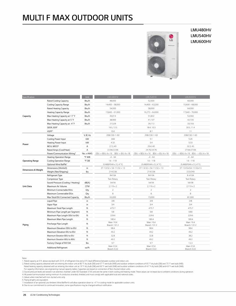
Specification Unit LMU480HV LMU540HV LMU600HV
Capacity
Rated Cooling Capacity Btu/h 48,000 52,500 60,000
Cooling Capacity Range Btu/h 14,400 ~ 58,000 14,400 ~ 63,200 15,600 ~ 68,000
Rated Heating Capacity Btu/h 54,000 58,000 64,000
Heating Capacity Range Btu/h 15,840 ~ 61,000 16,272 ~ 64,000 17,940 ~ 70,000
Max Heating Capacity at 17˚F Btu/h 49,014 51,832 53,560
Max Heating Capacity at 5˚F Btu/h 38,900 41,137 42,720
Max Heating Capacity at -4˚F Btu/h 27,529 29,112 33,193
SEER, EER5 19.5, 12.5 18.4, 10.3 20.5, 11.4
HSPF5 10.0 8.7 11
Power
Voltage V, Ø, Hz 208/230-1-60 208/230-1-60 208/230-1-60
Cooling Power Input kW 3.84 5.1 5.26
Heating Power Input kW 4.32 5.4 5.33
MCA, MOCP A 27.3, 40 29.4, 40 32.2, 45
Rated Amps (Cool/Heat) A 22.96/22.96 24.76/24.76 27.06/27.06
Power/Communication Wiring4 No. x AWG ODU --> BDU: 4 x 16 BDU --> IDU: 4 x 18 ODU --> BDU: 4 x 16 BDU --> IDU: 4 x 18 ODU --> BDU: 4 x 16 BDU --> IDU: 4 x 18
Operating Range
Heating Operation Range °F WB -4 ~ 64 -4 ~ 64 -4 ~ 64
Cooling Operation Range °F DB 14 ~ 118 14 ~ 118 14 ~ 118
Optional Wind Baffle7 ZLABGP04A x 2 (-4˚F) ZLABGP04A x 2 (-4˚F) ZLABGP04A x 2 (-4˚F)
Dimensions & WeightDimensions (WxHxD) in 37-13/32 × 54-11/32 × 13 37-13/32 × 54-11/32 × 13 37-13/32x54-11/32x13
Weight (Net/Shipping) lbs 214/236 214/236 223/249
Unit Data
Refrigerant Type R410A R410A R-410A
Compressor Type Twin Rotary Twin Rotary Twin Rotary
Sound Pressure (Cooling / Heating) dB(A) 54/56 54/56 56/58
Maximum Air Volume CFM 2,119 x 2 2,119 x 2 2,119 x 2
Minimum Connectable IDUs Qty 2 2 2
Maximum Connectable IDUs Qty 8 8 8
Max Total IDU Connected Capacity Btu/h 65,000 73,000 81,000
Piping
Liquid Pipe in 3/8 3/8 3/8
Vapor Pipe in 3/4 3/4 3/4
Maximum Total Pipe Length ft 475.7 475.7 475.7
Minimum Pipe Length per Segment ft 9.8 9.8 9.80
Maximum Pipe Length ODU to IDU ft 229.6 229.6 229.6
Maximum Main Pipe Length ft 180.4 180.4 180.4
Precharge Pipe Length ftMain: 16.4
Branch: 131.2Main: 16.4
Branch: 131.2Main: 16.4
Branch: 131.2
Maximum Elevation ODU to IDU ft 98.4 98.4 98.4
Maximum Elevation IDU to IDU ft 49.2 49.2 49.2
Maximum Elevation BDU to IDU ft 32.8 32.8 38.2
Maximum Elevation BDU to BDU ft 49.2 49.2 49.2
Factory Charge of R410A lbs 9.7 9.7 12.3
Additional Refrigerant oz/ftMain: 0.54
Branch: 0.22Main: 0.54
Branch: 0.22Main: 0.54
Branch: 0.22
MULTI F MAX OUTDOOR UNITSLMU480HVLMU540HVLMU600HV
Note:1. Rated capacity at 0 ft. above sea level with 25 ft. of refrigerant line and a 0 ft. level difference between outdoor and indoor unit.2. Rated cooling capacity obtained with air entering the indoor unit at 80˚F dry bulb (DB) and 67˚F wet bulb (WB) and outdoor ambient conditions of 95˚F dry bulb (DB) and 75˚F wet bulb (WB). Rated heating capacity obtained with air entering the indoor unit at 70˚F dry bulb (DB) and 60˚F wet bulb (WB) and outdoor ambient conditions of 47˚F dry bulb (DB) and 43˚F wet bulb (WB). For capacity information, see engineering manual capacity tables. Capacities are based on connection of Non-Ducted indoor units.3. Sound pressure levels are tested in an anechoic chamber under ISO Standard 3745 and are the same in both cooling and heating mode. These values can increase due to ambient conditions during operation.4. All power/communication wiring minimum 4-conductor, stranded, shielded, and must comply with applicable local and national codes. 5. Values when matched with non-ducted units only. 6. Piping lengths are equivalent.7. Installation of an optional Low Ambient Wind Baffle Kit will allow operation down to -4˚F in cooling mode for applicable outdoor units.8. Due to our commitment to continued innovation, some specifications may be changed without notification.
26
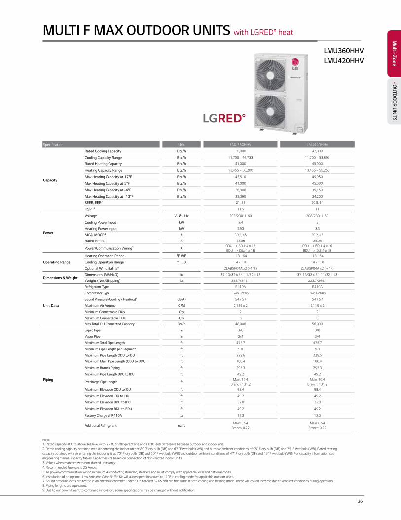
Specification Unit LMU360HHV LMU420HHV
Capacity
Rated Cooling Capacity Btu/h 36,000 42,000
Cooling Capacity Range Btu/h 11,700 ~ 46,733 11,700 ~ 53,897
Rated Heating Capacity Btu/h 41,000 45,000
Heating Capacity Range Btu/h 13,455 ~ 50,200 13,455 ~ 55,256
Max Heating Capacity at 17°F Btu/h 45,510 49,950
Max Heating Capacity at 5°F Btu/h 41,000 45,000
Max Heating Capacity at -4°F Btu/h 36,900 39,150
Max Heating Capacity at -13°F Btu/h 32,390 34,200
SEER, EER3 21, 15 20.5, 14
HSPF3 11.5 11
Power
Voltage V- Ø - Hz 208/230-1-60 208/230-1-60
Cooling Power Input kW 2.4 3
Heating Power Input kW 2.93 3.3
MCA, MOCP4 A 30.2, 45 30.2, 45
Rated Amps A 25.06 25.06
Power/Communication Wiring5 AODU --> BDU: 4 x 16 BDU --> IDU: 4 x 18
ODU --> BDU: 4 x 16 BDU --> IDU: 4 x 18
Operating Range
Heating Operation Range °F WB -13 - 64 -13 - 64
Cooling Operation Range °F DB 14 - 118 14 - 118
Optional Wind Baffle6 ZLABGP04A x2 (-4˚F) ZLABGP04A x2 (-4˚F)
Dimensions & WeightDimensions (WxHxD) in 37-13/32 x 54-11/32 x 13 37-13/32 x 54-11/32 x 13
Weight (Net/Shipping) lbs 222.7/249.1 222.7/249.1
Unit Data
Refrigerant Type R410A R410A
Compressor Type Twin Rotary Twin Rotary
Sound Pressure (Cooling / Heating)7 dB(A) 54 / 57 54 / 57
Maximum Air Volume CFM 2,119 x 2 2,119 x 2
Minimum Connectable IDUs Qty 2 2
Maximum Connectable IDUs Qty 5 6
Max Total IDU Connected Capacity Btu/h 48,000 56,000
Piping
Liquid Pipe in 3/8 3/8
Vapor Pipe in 3/4 3/4
Maximum Total Pipe Length ft 475.7 475.7
Minimum Pipe Length per Segment ft 9.8 9.8
Maximum Pipe Length ODU to IDU ft 229.6 229.6
Maximum Main Pipe Length (ODU to BDU) ft 180.4 180.4
Maximum Branch Piping ft 295.3 295.3
Maximum Pipe Length BDU to IDU ft 49.2 49.2
Precharge Pipe Length ftMain: 16.4
Branch: 131.2Main: 16.4
Branch: 131.2Maximum Elevation ODU to IDU ft 98.4 98.4
Maximum Elevation IDU to IDU ft 49.2 49.2
Maximum Elevation BDU to IDU ft 32.8 32.8
Maximum Elevation BDU to BDU ft 49.2 49.2
Factory Charge of R410A lbs 12.3 12.3
Additional Refrigerant oz/ftMain: 0.54
Branch: 0.22Main: 0.54
Branch: 0.22
Multi-ZoneM
ulti-Zone• O
UTD
OO
R UN
ITS
MULTI F MAX OUTDOOR UNITS with LGRED° heat
LMU360HHVLMU420HHV
Note:1. Rated capacity at 0 ft. above sea level with 25 ft. of refrigerant line and a 0 ft. level difference between outdoor and indoor unit. 2. Rated cooling capacity obtained with air entering the indoor unit at 80˚F dry bulb (DB) and 67˚F wet bulb (WB) and outdoor ambient conditions of 95˚F dry bulb (DB) and 75˚F wet bulb (WB). Rated heating capacity obtained with air entering the indoor unit at 70˚F dry bulb (DB) and 60˚F wet bulb (WB) and outdoor ambient conditions of 47˚F dry bulb (DB) and 43˚F wet bulb (WB). For capacity information, see engineering manual capacity tables. Capacities are based on connection of Non-Ducted indoor units. 3. Values when matched with non-ducted units only.4. Recommended fuse sze is 25 Amps.5. All power/communication wiring minimum 4-conductor, stranded, shielded, and must comply with applicable local and national codes. 6. Installation of an optional Low Ambient Wind Baffle Kit will allow operation down to -4˚F in cooling mode for applicable outdoor units. 7. Sound pressure levels are tested in an anechoic chamber under ISO Standard 3745 and are the same in both cooling and heating mode. These values can increase due to ambient conditions during operation. 8. Piping lengths are equivalent. 9. Due to our commitment to continued innovation, some specifications may be changed without notification.
27 LG Air Conditioning Technologies
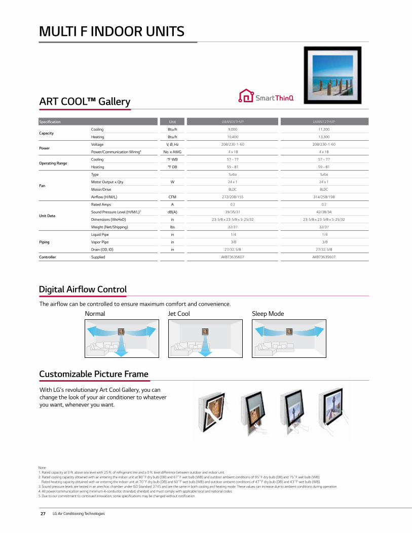
Specification Unit LMAN097HVP LMAN127HVP
CapacityCooling Btu/h 9,000 11,200
Heating Btu/h 10,400 13,300
PowerVoltage V, Ø, Hz 208/230-1-60 208/230-1-60
Power/Communication Wiring4 No. x AWG 4 x 18 4 x 18
Operating RangeCooling °F WB 57 ~ 77 57 ~ 77
Heating °F DB 59 ~ 81 59 ~ 81
Fan
Type Turbo Turbo
Motor Output x Qty W 24 x 1 24 x 1
Motor/Drive BLDC BLDC
Airflow (H/M/L) CFM 272/208/155 314/258/198
Unit Data
Rated Amps A 0.2 0.2
Sound Pressure Level (H/M/L)3 dB(A) 39/35/31 42/38/34
Dimensions (WxHxD) in 23-5/8 x 23-5/8 x 5-25/32 23-5/8 x 23-5/8 x 5-25/32
Weight (Net/Shipping) lbs 32/37 32/37
Piping
Liquid Pipe in 1/4 1/4
Vapor Pipe in 3/8 3/8
Drain (OD, ID) in 27/32, 5/8 27/32, 5/8
Controller Supplied AKB73635607 AKB73635607
ART COOL™ Gallery
MULTI F INDOOR UNITS
Note:1. Rated capacity at 0 ft. above sea level with 25 ft. of refrigerant line and a 0 ft. level difference between outdoor and indoor unit.2. Rated cooling capacity obtained with air entering the indoor unit at 80˚F dry bulb (DB) and 67˚F wet bulb (WB) and outdoor ambient conditions of 95˚F dry bulb (DB) and 75˚F wet bulb (WB). Rated heating capacity obtained with air entering the indoor unit at 70˚F dry bulb (DB) and 60˚F wet bulb (WB) and outdoor ambient conditions of 47˚F dry bulb (DB) and 43˚F wet bulb (WB).3. Sound pressure levels are tested in an anechoic chamber under ISO Standard 3745 and are the same in both cooling and heating mode. These values can increase due to ambient conditions during operation.4. All power/communication wiring minimum 4-conductor, stranded, shielded, and must comply with applicable local and national codes. 5. Due to our commitment to continued innovation, some specifications may be changed without notification.
Digital Airflow Control
Customizable Picture Frame
The airflow can be controlled to ensure maximum comfort and convenience.
With LG’s revolutionary Art Cool Gallery, you can change the look of your air conditioner to whatever you want, whenever you want.
Normal Jet Cool Sleep Mode
28
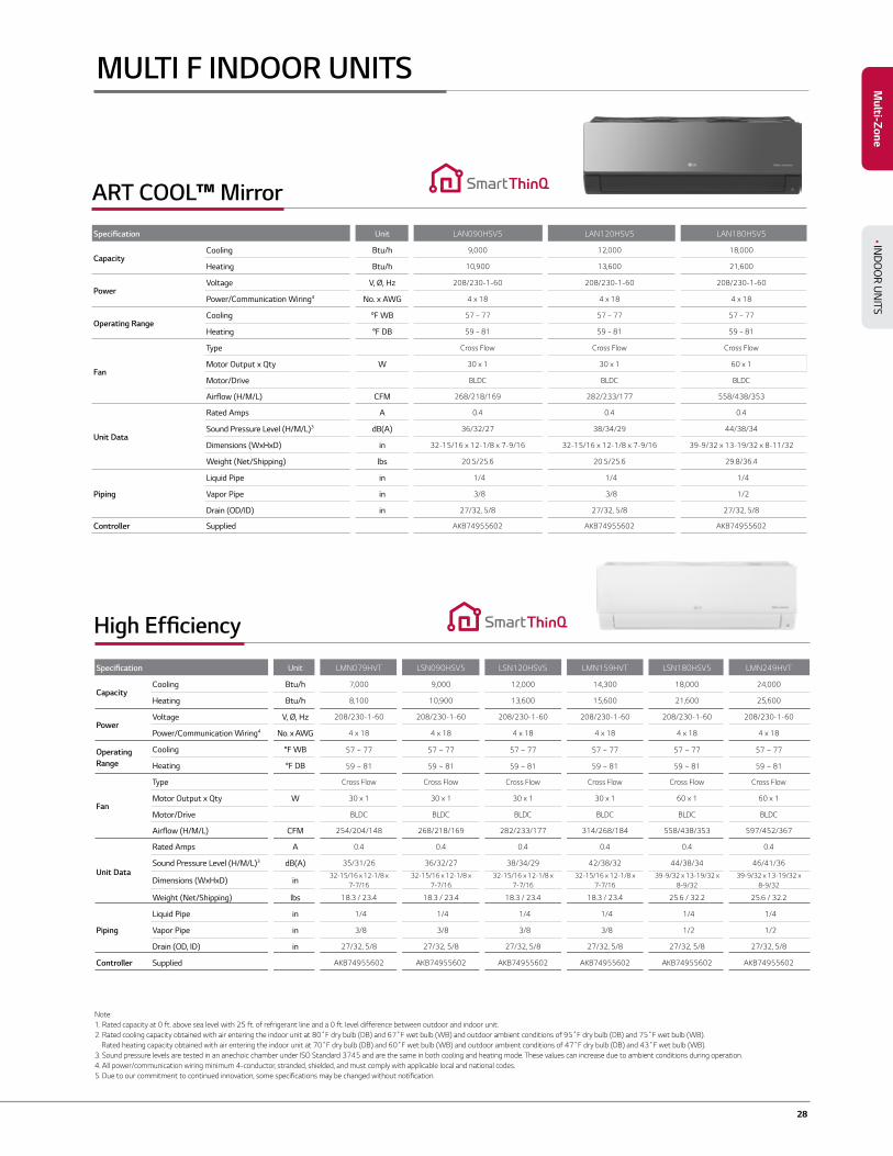
MULTI F INDOOR UNITS
Note:1. Rated capacity at 0 ft. above sea level with 25 ft. of refrigerant line and a 0 ft. level difference between outdoor and indoor unit.2. Rated cooling capacity obtained with air entering the indoor unit at 80˚F dry bulb (DB) and 67˚F wet bulb (WB) and outdoor ambient conditions of 95˚F dry bulb (DB) and 75˚F wet bulb (WB). Rated heating capacity obtained with air entering the indoor unit at 70˚F dry bulb (DB) and 60˚F wet bulb (WB) and outdoor ambient conditions of 47˚F dry bulb (DB) and 43˚F wet bulb (WB).3. Sound pressure levels are tested in an anechoic chamber under ISO Standard 3745 and are the same in both cooling and heating mode. These values can increase due to ambient conditions during operation.4. All power/communication wiring minimum 4-conductor, stranded, shielded, and must comply with applicable local and national codes. 5. Due to our commitment to continued innovation, some specifications may be changed without notification.
High Efficiency
Specification Unit LMN079HVT LSN090HSV5 LSN120HSV5 LMN159HVT LSN180HSV5 LMN249HVT
CapacityCooling Btu/h 7,000 9,000 12,000 14,300 18,000 24,000
Heating Btu/h 8,100 10,900 13,600 15,600 21,600 25,600
PowerVoltage V, Ø, Hz 208/230-1-60 208/230-1-60 208/230-1-60 208/230-1-60 208/230-1-60 208/230-1-60
Power/Communication Wiring4 No. x AWG 4 x 18 4 x 18 4 x 18 4 x 18 4 x 18 4 x 18
Operating Range
Cooling °F WB 57 ~ 77 57 ~ 77 57 ~ 77 57 ~ 77 57 ~ 77 57 ~ 77
Heating °F DB 59 ~ 81 59 ~ 81 59 ~ 81 59 ~ 81 59 ~ 81 59 ~ 81
Fan
Type Cross Flow Cross Flow Cross Flow Cross Flow Cross Flow Cross Flow
Motor Output x Qty W 30 x 1 30 x 1 30 x 1 30 x 1 60 x 1 60 x 1
Motor/Drive BLDC BLDC BLDC BLDC BLDC BLDC
Airflow (H/M/L) CFM 254/204/148 268/218/169 282/233/177 314/268/184 558/438/353 597/452/367
Unit Data
Rated Amps A 0.4 0.4 0.4 0.4 0.4 0.4
Sound Pressure Level (H/M/L)3 dB(A) 35/31/26 36/32/27 38/34/29 42/38/32 44/38/34 46/41/36
Dimensions (WxHxD) in32-15/16 x 12-1/8 x
7-7/1632-15/16 x 12-1/8 x
7-7/1632-15/16 x 12-1/8 x
7-7/1632-15/16 x 12-1/8 x
7-7/1639-9/32 x 13-19/32 x
8-9/3239-9/32 x 13-19/32 x
8-9/32
Weight (Net/Shipping) lbs 18.3 / 23.4 18.3 / 23.4 18.3 / 23.4 18.3 / 23.4 25.6 / 32.2 25.6 / 32.2
Piping
Liquid Pipe in 1/4 1/4 1/4 1/4 1/4 1/4
Vapor Pipe in 3/8 3/8 3/8 3/8 1/2 1/2
Drain (OD, ID) in 27/32, 5/8 27/32, 5/8 27/32, 5/8 27/32, 5/8 27/32, 5/8 27/32, 5/8
Controller Supplied AKB74955602 AKB74955602 AKB74955602 AKB74955602 AKB74955602 AKB74955602
Multi-Zone
• IND
OO
R UN
ITS
Specification Unit LAN090HSV5 LAN120HSV5 LAN180HSV5
CapacityCooling Btu/h 9,000 12,000 18,000
Heating Btu/h 10,900 13,600 21,600
PowerVoltage V, Ø, Hz 208/230-1-60 208/230-1-60 208/230-1-60
Power/Communication Wiring4 No. x AWG 4 x 18 4 x 18 4 x 18
Operating RangeCooling °F WB 57 ~ 77 57 ~ 77 57 ~ 77
Heating °F DB 59 ~ 81 59 ~ 81 59 ~ 81
Fan
Type Cross Flow Cross Flow Cross Flow
Motor Output x Qty W 30 x 1 30 x 1 60 x 1
Motor/Drive BLDC BLDC BLDC
Airflow (H/M/L) CFM 268/218/169 282/233/177 558/438/353
Unit Data
Rated Amps A 0.4 0.4 0.4
Sound Pressure Level (H/M/L)3 dB(A) 36/32/27 38/34/29 44/38/34
Dimensions (WxHxD) in 32-15/16 x 12-1/8 x 7-9/16 32-15/16 x 12-1/8 x 7-9/16 39-9/32 x 13-19/32 x 8-11/32
Weight (Net/Shipping) lbs 20.5/25.6 20.5/25.6 29.8/36.4
Piping
Liquid Pipe in 1/4 1/4 1/4
Vapor Pipe in 3/8 3/8 1/2
Drain (OD/ID) in 27/32, 5/8 27/32, 5/8 27/32, 5/8
Controller Supplied AKB74955602 AKB74955602 AKB74955602
ART COOL™ Mirror
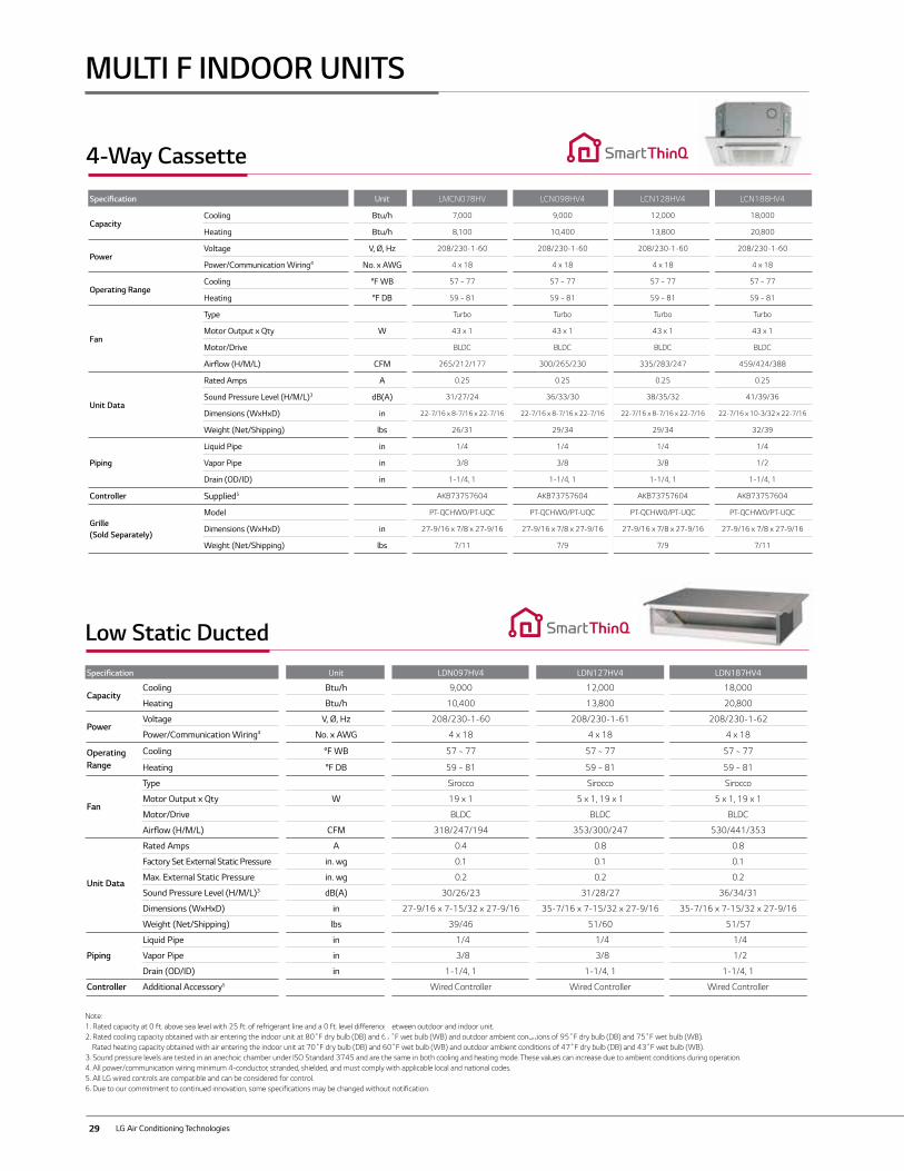
29 LG Air Conditioning Technologies
MULTI F INDOOR UNITS
Note:1. Rated capacity at 0 ft. above sea level with 25 ft. of refrigerant line and a 0 ft. level difference between outdoor and indoor unit.2. Rated cooling capacity obtained with air entering the indoor unit at 80˚F dry bulb (DB) and 67˚F wet bulb (WB) and outdoor ambient conditions of 95˚F dry bulb (DB) and 75˚F wet bulb (WB). Rated heating capacity obtained with air entering the indoor unit at 70˚F dry bulb (DB) and 60˚F wet bulb (WB) and outdoor ambient conditions of 47˚F dry bulb (DB) and 43˚F wet bulb (WB).3. Sound pressure levels are tested in an anechoic chamber under ISO Standard 3745 and are the same in both cooling and heating mode. These values can increase due to ambient conditions during operation.4. All power/communication wiring minimum 4-conductor, stranded, shielded, and must comply with applicable local and national codes. 5. All LG wired controls are compatible and can be considered for control.6. Due to our commitment to continued innovation, some specifications may be changed without notification.
Low Static DuctedSpecification Unit LDN097HV4 LDN127HV4 LDN187HV4
CapacityCooling Btu/h 9,000 12,000 18,000
Heating Btu/h 10,400 13,800 20,800
PowerVoltage V, Ø, Hz 208/230-1-60 208/230-1-61 208/230-1-62
Power/Communication Wiring4 No. x AWG 4 x 18 4 x 18 4 x 18
Operating Range
Cooling °F WB 57 ~ 77 57 ~ 77 57 ~ 77
Heating °F DB 59 ~ 81 59 ~ 81 59 ~ 81
Fan
Type Sirocco Sirocco Sirocco
Motor Output x Qty W 19 x 1 5 x 1, 19 x 1 5 x 1, 19 x 1
Motor/Drive BLDC BLDC BLDC
Airflow (H/M/L) CFM 318/247/194 353/300/247 530/441/353
Unit Data
Rated Amps A 0.4 0.8 0.8
Factory Set External Static Pressure in. wg 0.1 0.1 0.1
Max. External Static Pressure in. wg 0.2 0.2 0.2
Sound Pressure Level (H/M/L)3 dB(A) 30/26/23 31/28/27 36/34/31
Dimensions (WxHxD) in 27-9/16 x 7-15/32 x 27-9/16 35-7/16 x 7-15/32 x 27-9/16 35-7/16 x 7-15/32 x 27-9/16
Weight (Net/Shipping) lbs 39/46 51/60 51/57
Piping
Liquid Pipe in 1/4 1/4 1/4
Vapor Pipe in 3/8 3/8 1/2
Drain (OD/ID) in 1-1/4, 1 1-1/4, 1 1-1/4, 1
Controller Additional Accessory5 Wired Controller Wired Controller Wired Controller
4-Way Cassette
Specification Unit LMCN078HV LCN098HV4 LCN128HV4 LCN188HV4
CapacityCooling Btu/h 7,000 9,000 12,000 18,000
Heating Btu/h 8,100 10,400 13,800 20,800
PowerVoltage V, Ø, Hz 208/230-1-60 208/230-1-60 208/230-1-60 208/230-1-60
Power/Communication Wiring4 No. x AWG 4 x 18 4 x 18 4 x 18 4 x 18
Operating RangeCooling °F WB 57 ~ 77 57 ~ 77 57 ~ 77 57 ~ 77
Heating °F DB 59 ~ 81 59 ~ 81 59 ~ 81 59 ~ 81
Fan
Type Turbo Turbo Turbo Turbo
Motor Output x Qty W 43 x 1 43 x 1 43 x 1 43 x 1
Motor/Drive BLDC BLDC BLDC BLDC
Airflow (H/M/L) CFM 265/212/177 300/265/230 335/283/247 459/424/388
Unit Data
Rated Amps A 0.25 0.25 0.25 0.25
Sound Pressure Level (H/M/L)3 dB(A) 31/27/24 36/33/30 38/35/32 41/39/36
Dimensions (WxHxD) in 22-7/16 x 8-7/16 x 22-7/16 22-7/16 x 8-7/16 x 22-7/16 22-7/16 x 8-7/16 x 22-7/16 22-7/16 x 10-3/32 x 22-7/16
Weight (Net/Shipping) lbs 26/31 29/34 29/34 32/39
Piping
Liquid Pipe in 1/4 1/4 1/4 1/4
Vapor Pipe in 3/8 3/8 3/8 1/2
Drain (OD/ID) in 1-1/4, 1 1-1/4, 1 1-1/4, 1 1-1/4, 1
Controller Supplied5 AKB73757604 AKB73757604 AKB73757604 AKB73757604
Grille (Sold Separately)
Model PT-QCHW0/PT-UQC PT-QCHW0/PT-UQC PT-QCHW0/PT-UQC PT-QCHW0/PT-UQC
Dimensions (WxHxD) in 27-9/16 x 7/8 x 27-9/16 27-9/16 x 7/8 x 27-9/16 27-9/16 x 7/8 x 27-9/16 27-9/16 x 7/8 x 27-9/16
Weight (Net/Shipping) lbs 7/11 7/9 7/9 7/11
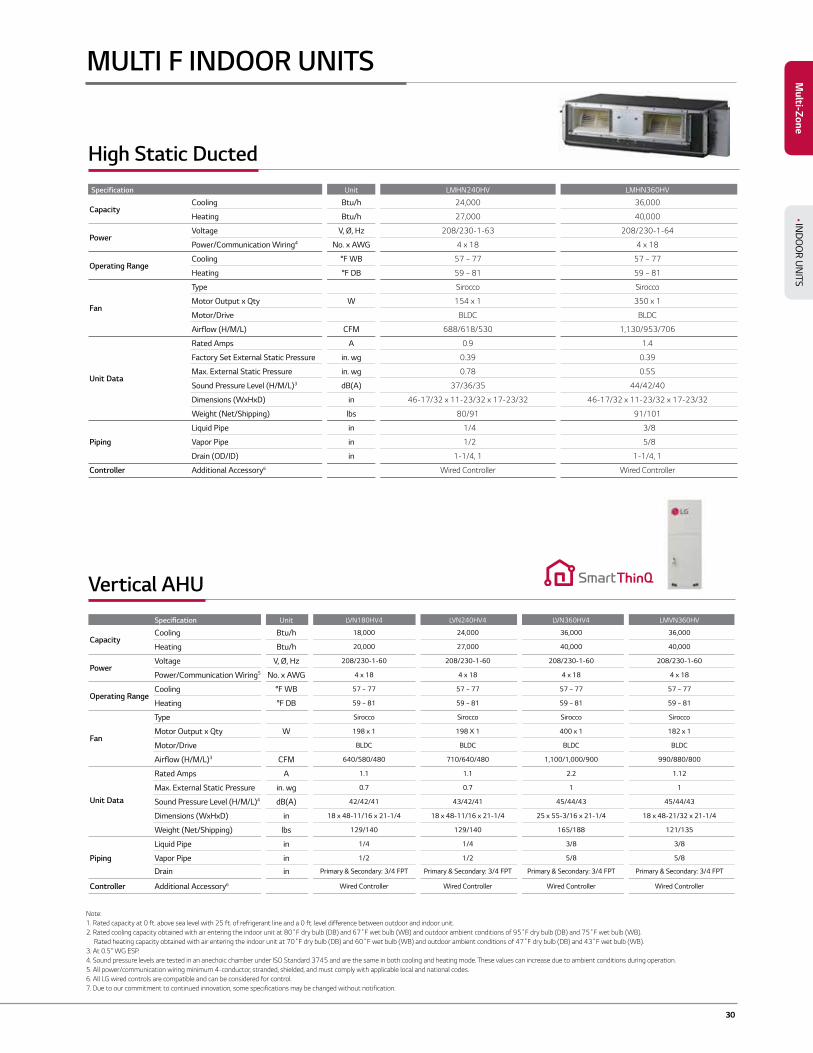
30
High Static Ducted Specification Unit LMHN240HV LMHN360HV
CapacityCooling Btu/h 24,000 36,000
Heating Btu/h 27,000 40,000
PowerVoltage V, Ø, Hz 208/230-1-63 208/230-1-64
Power/Communication Wiring4 No. x AWG 4 x 18 4 x 18
Operating RangeCooling °F WB 57 ~ 77 57 ~ 77
Heating °F DB 59 ~ 81 59 ~ 81
Fan
Type Sirocco Sirocco
Motor Output x Qty W 154 x 1 350 x 1
Motor/Drive BLDC BLDC
Airflow (H/M/L) CFM 688/618/530 1,130/953/706
Unit Data
Rated Amps A 0.9 1.4
Factory Set External Static Pressure in. wg 0.39 0.39
Max. External Static Pressure in. wg 0.78 0.55
Sound Pressure Level (H/M/L)3 dB(A) 37/36/35 44/42/40
Dimensions (WxHxD) in 46-17/32 x 11-23/32 x 17-23/32 46-17/32 x 11-23/32 x 17-23/32
Weight (Net/Shipping) lbs 80/91 91/101
Piping
Liquid Pipe in 1/4 3/8
Vapor Pipe in 1/2 5/8
Drain (OD/ID) in 1-1/4, 1 1-1/4, 1
Controller Additional Accessory6 Wired Controller Wired Controller
MULTI F INDOOR UNITS
Note:1. Rated capacity at 0 ft. above sea level with 25 ft. of refrigerant line and a 0 ft. level difference between outdoor and indoor unit.2. Rated cooling capacity obtained with air entering the indoor unit at 80˚F dry bulb (DB) and 67˚F wet bulb (WB) and outdoor ambient conditions of 95˚F dry bulb (DB) and 75˚F wet bulb (WB). Rated heating capacity obtained with air entering the indoor unit at 70˚F dry bulb (DB) and 60˚F wet bulb (WB) and outdoor ambient conditions of 47˚F dry bulb (DB) and 43˚F wet bulb (WB).3. At 0.5" WG ESP.4. Sound pressure levels are tested in an anechoic chamber under ISO Standard 3745 and are the same in both cooling and heating mode. These values can increase due to ambient conditions during operation.5. All power/communication wiring minimum 4-conductor, stranded, shielded, and must comply with applicable local and national codes. 6. All LG wired controls are compatible and can be considered for control.7. Due to our commitment to continued innovation, some specifications may be changed without notification.
Multi-Zone
• IND
OO
R UN
ITS
Vertical AHU Specification Unit LVN180HV4 LVN240HV4 LVN360HV4 LMVN360HV
CapacityCooling Btu/h 18,000 24,000 36,000 36,000
Heating Btu/h 20,000 27,000 40,000 40,000
PowerVoltage V, Ø, Hz 208/230-1-60 208/230-1-60 208/230-1-60 208/230-1-60
Power/Communication Wiring5 No. x AWG 4 x 18 4 x 18 4 x 18 4 x 18
Operating RangeCooling °F WB 57 ~ 77 57 ~ 77 57 ~ 77 57 ~ 77
Heating °F DB 59 ~ 81 59 ~ 81 59 ~ 81 59 ~ 81
Fan
Type Sirocco Sirocco Sirocco Sirocco
Motor Output x Qty W 198 x 1 198 X 1 400 x 1 182 x 1
Motor/Drive BLDC BLDC BLDC BLDC
Airflow (H/M/L)3 CFM 640/580/480 710/640/480 1,100/1,000/900 990/880/800
Unit Data
Rated Amps A 1.1 1.1 2.2 1.12
Max. External Static Pressure in. wg 0.7 0.7 1 1
Sound Pressure Level (H/M/L)4 dB(A) 42/42/41 43/42/41 45/44/43 45/44/43
Dimensions (WxHxD) in 18 x 48-11/16 x 21-1/4 18 x 48-11/16 x 21-1/4 25 x 55-3/16 x 21-1/4 18 x 48-21/32 x 21-1/4
Weight (Net/Shipping) lbs 129/140 129/140 165/188 121/135
Piping
Liquid Pipe in 1/4 1/4 3/8 3/8
Vapor Pipe in 1/2 1/2 5/8 5/8
Drain in Primary & Secondary: 3/4 FPT Primary & Secondary: 3/4 FPT Primary & Secondary: 3/4 FPT Primary & Secondary: 3/4 FPT
Controller Additional Accessory6 Wired Controller Wired Controller Wired Controller Wired Controller
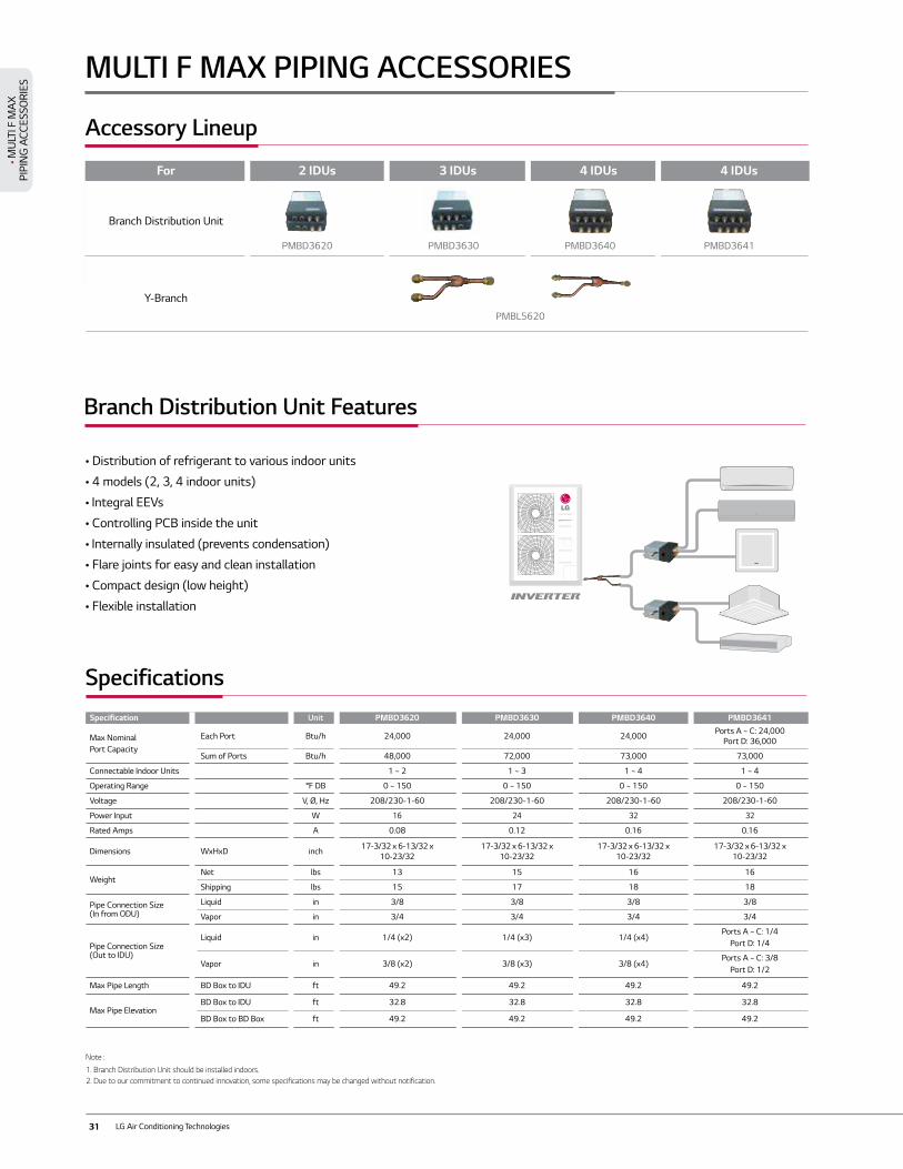
31 LG Air Conditioning Technologies
• Distribution of refrigerant to various indoor units
• 4 models (2, 3, 4 indoor units)
• Integral EEVs
• Controlling PCB inside the unit
• Internally insulated (prevents condensation)
• Flare joints for easy and clean installation
• Compact design (low height)
• Flexible installation
Distributor Box
Y Branch
For 2 IDUs 3 IDUs 4 IDUs 4 IDUs
Branch Distribution Unit
Y-Branch
PMBD3640 PMBD3641PMBD3620 PMBD3630
PMBL5620
Specification Unit PMBD3620 PMBD3630 PMBD3640 PMBD3641
Max Nominal Port Capacity
Each Port Btu/h 24,000 24,000 24,000 Ports A ~ C: 24,000 Port D: 36,000
Sum of Ports Btu/h 48,000 72,000 73,000 73,000
Connectable Indoor Units 1 ~ 2 1 ~ 3 1 ~ 4 1 ~ 4
Operating Range °F DB 0 ~ 150 0 ~ 150 0 ~ 150 0 ~ 150
Voltage V, Ø, Hz 208/230-1-60 208/230-1-60 208/230-1-60 208/230-1-60
Power Input W 16 24 32 32
Rated Amps A 0.08 0.12 0.16 0.16
Dimensions WxHxD inch 17-3/32 x 6-13/32 x 10-23/32
17-3/32 x 6-13/32 x 10-23/32
17-3/32 x 6-13/32 x 10-23/32
17-3/32 x 6-13/32 x 10-23/32
WeightNet lbs 13 15 16 16
Shipping lbs 15 17 18 18
Pipe Connection Size(In from ODU)
Liquid in 3/8 3/8 3/8 3/8
Vapor in 3/4 3/4 3/4 3/4
Pipe Connection Size(Out to IDU)
Liquid in 1/4 (x2) 1/4 (x3) 1/4 (x4)Ports A ~ C: 1/4
Port D: 1/4
Vapor in 3/8 (x2) 3/8 (x3) 3/8 (x4)Ports A ~ C: 3/8
Port D: 1/2
Max Pipe Length BD Box to IDU ft 49.2 49.2 49.2 49.2
Max Pipe ElevationBD Box to IDU ft 32.8 32.8 32.8 32.8
BD Box to BD Box ft 49.2 49.2 49.2 49.2
Note :
1. Branch Distribution Unit should be installed indoors. 2. Due to our commitment to continued innovation, some specifications may be changed without notification.
MULTI F MAX PIPING ACCESSORIES
Accessory Lineup
Branch Distribution Unit Features
Specifications
• MU
LTI F
MA
XPI
PIN
G A
CCES
SORI
ES
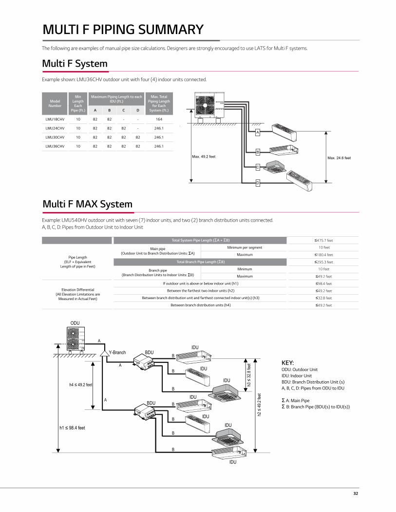
32
KEY:ODU: Outdoor UnitIDU: Indoor UnitBDU: Branch Distribution Unit (s)A, B, C, D: Pipes from ODU to IDU
Σ A: Main PipeΣ B: Branch Pipe (BDU(s) to IDU(s))
Max. 49.2 feet Max. 24.6 feet
A
B
C
D
Multi F System Example: LMU36CHV outdoor unit with four (4) indoor units connected.ODU: Outdoor Unit.IDU: Indoor Unit.A, B, C, D: Pipes from Outdoor Unit to Indoor Unit.
Outdoor Unit Minimum Length for Each Pipe (ft.)
Maximum Piping Length to Each Indoor Unit (ft.) Maximum Total Piping Length for Each System (ft.)A B C D
LMU18CHV 10 82 82 - - 164LMU24CHV 10 82 82 82 - 246.1LMU30CHV 10 82 82 82 82 246.1LMU36CHV 10 82 82 82 82 246.1
Multi F Outdoor Unit Refrigerant Piping System Limitations.
Example: LMU540HV outdoor unit with seven (7) indoor units, and two (2) branch distribution units connected.ODU: Outdoor Unit.IDU: Indoor Unit.BD: Branch Distribution Unit(s).
B
A
h2 ≤
49.2
feet
A
h3 ≤
32.8
feet
h4 ≤ 49.2 feet
h1 ≤ 98.4 feet
BDU Y-Branch
BDU
IDU
A
ODU
IDU
IDU
IDU
IDU
IDU
IDU
B
B
B
B
B
B
Multi F MAX Outdoor Unit Refrigerant Piping System Limitations.
Pipe Length(ELF = Equivalent
Length of pipe in Feet)
Main pipe (Outdoor Unit to Minimum 10 feetMaximum
Branch pipe (Branch Distribu-tion Units to Indoor Units: B)
Minimum 10 feetMaximum
Elevation Differential(All Elevation
Limitations areMeasured in Actual
Feet)
If outdoor unit is above or below indoor unit (h1)Between the farthest two indoor units (h2)
Between branch distribution unit and farthestconnected indoor unit(s) (h3)
Between branch distribution units (h4)
Multi F MAX Piping Sizes.
Piping Main Pipe A (inch) Branch Pipe B
Liquid Ø3/8 Depends on the sizeof the indoor unit pipingGas Ø3/4
Example: LMU540HV outdoor unit with four (4) indoor units, and one (1) branch distribution unit connected.ODU: Outdoor Unit.IDU: Indoor Unit.BDU: Branch Distribution Unit.A: Main Pipe.B: Branch Pipe (Branch Distribution Unit to
A
h2 ≤ 49.2 feet
h3 ≤ 32.8 feeth1 ≤ 98.4 feet
BDU
ODU
IDU
IDU
IDU
IDU
B
B
B
B
Multi F MAX System with One Branch Distribution Unit
Multi F MAX System with Two Branch Distribution Units
Total System Pipe Length (ΣA + ΣB) ≤475.7 feet
Pipe Length (ELF = Equivalent
Length of pipe in Feet)
Main pipe (Outdoor Unit to Branch Distribution Units: ΣA)
Minimum per segment 10 feet
Maximum ≤180.4 feet
Total Branch Pipe Length (ΣB) ≤295.3 feet
Branch pipe (Branch Distribution Units to Indoor Units: ΣB)
Minimum 10 feet
Maximum ≤49.2 feet
Elevation Differential (All Elevation Limitations are
Measured in Actual Feet)
If outdoor unit is above or below indoor unit (h1) ≤98.4 feet
Between the farthest two indoor units (h2) ≤49.2 feet
Between branch distribution unit and farthest connected indoor unit(s) (h3) ≤32.8 feet
Between branch distribution units (h4) ≤49.2 feet
MULTI F PIPING SUMMARY
Multi F System
Multi F MAX System
Model Number
Min Length Each
Pipe (ft.)
Maximum Piping Length to each IDU (ft.)
Max. Total Piping Length
for Each System (ft.)A B C D
LMU18CHV 10 82 82 - - 164
LMU24CHV 10 82 82 82 - 246.1
LMU30CHV 10 82 82 82 82 246.1
LMU36CHV 10 82 82 82 82 246.1
Example shown: LMU36CHV outdoor unit with four (4) indoor units connected.
Example: LMU540HV outdoor unit with seven (7) indoor units, and two (2) branch distribution units connected.A, B, C, D: Pipes from Outdoor Unit to Indoor Unit
The following are examples of manual pipe size calculations. Designers are strongly encouraged to use LATS for Multi F systems.
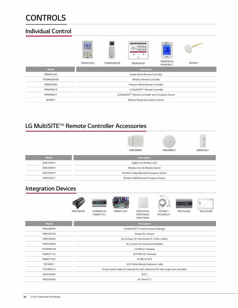
33 LG Air Conditioning Technologies
Individual Control
Model Description
PREMTC00U Simple Wired Remote Controller
PQWRHQ0FDB Wireless Remote Controller
PREMTA000 Premium Wired Remote Controller
PREMTBVC0 LG MultiSITE™ Remote Controller
PREMTBVC1 LG MultiSITE™ Remote Controller with Occupancy Sensor
ZRTBS01 Remote Temperature Button Sensor
PREMTBVC0PREMTBVC1PREMTA000PQWRHQ0FDB
Integration Devices
Model Description
PBACNBTR0 LG MultiSITE™ Communications Manager
PDRYCB100 Simple Dry Contact
PDRYCB300 Dry Contact for Thermostat (5-12Vdc, 24Vac)
PDRYCB400 Dry Contact for Economizer/Setback
PLNWKB100 LonWorks® Gateway
PQNFB17C2 ACP BACnet® Gateway
PMNFP14A1 PI 485 for DFS
PZCWRC1 32.8' Wired Remote Extension Cable
PZCWRCG3 Group Control Cable Kit (required for each additional A/H with single zone controller)
PACP5A000 ACP 5
PACS5A000 AC Smart™ 5
PDRYCB100PDRYCB300PDRYCB400
PZCWRC1PZCWRCG3
PMNFP14A1 PACP5A000 PACS5A000
CONTROLS
PLNWKB100PQNFB17C2
ZRTBS01
PBACNBTR0
LG MultiSITE™ Remote Controller Accessories
ZVRCZDWS1 ZVRCZWOC1 ZVRCZCOC1
Model Description
ZVRCZPWC1 ZigBee Pro Wireless Card
ZVRCZDWS1 Wireless Door & Window Switch
ZVRCZWOC1 Wireless Ceiling Mounted Occupancy Sensor
ZVRCZCOC1 Wireless Wall Mounted Occupancy Sensor
PREMTC00U
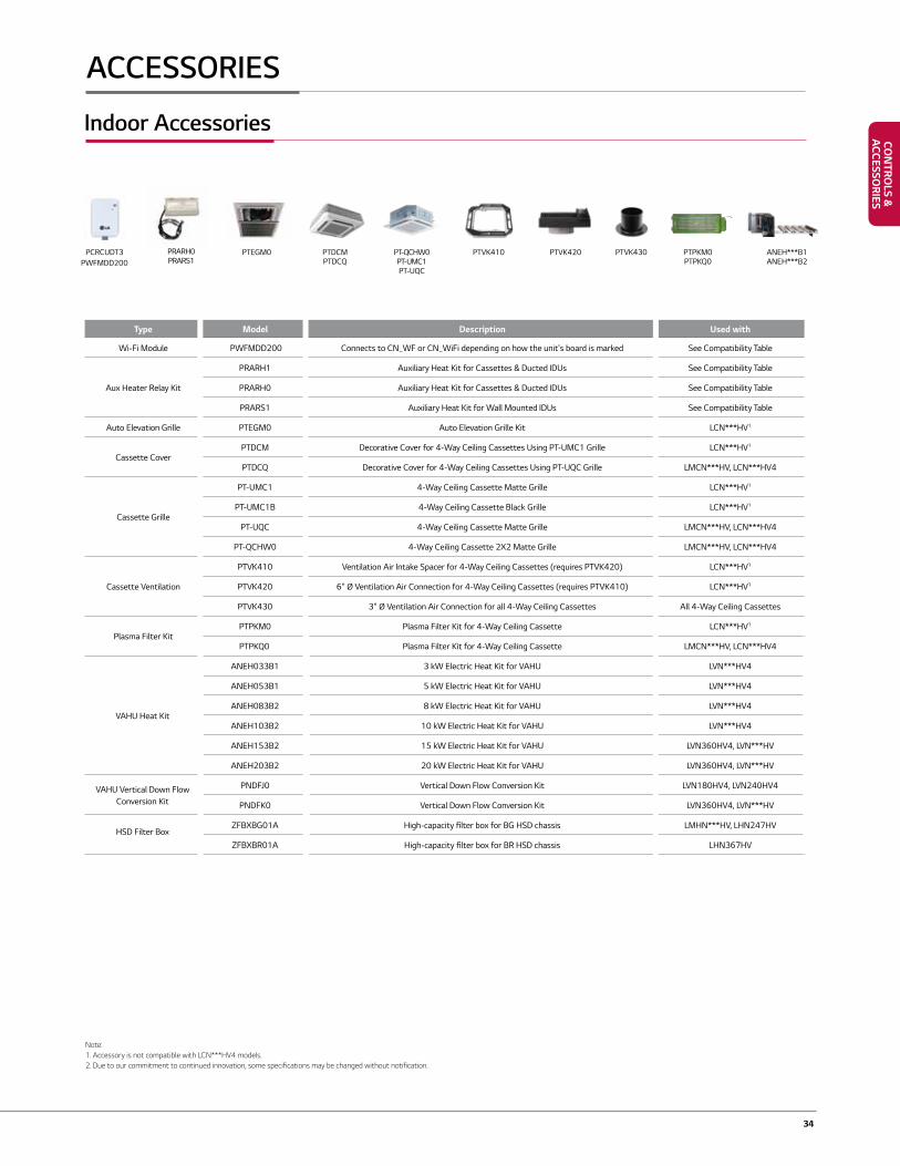
34
Type Model Description Used with
Wi-Fi Module PWFMDD200 Connects to CN_WF or CN_WiFi depending on how the unit's board is marked See Compatibility Table
Aux Heater Relay Kit
PRARH1 Auxiliary Heat Kit for Cassettes & Ducted IDUs See Compatibility Table
PRARH0 Auxiliary Heat Kit for Cassettes & Ducted IDUs See Compatibility Table
PRARS1 Auxiliary Heat Kit for Wall Mounted IDUs See Compatibility Table
Auto Elevation Grille PTEGM0 Auto Elevation Grille Kit LCN***HV1
Cassette CoverPTDCM Decorative Cover for 4-Way Ceiling Cassettes Using PT-UMC1 Grille LCN***HV1
PTDCQ Decorative Cover for 4-Way Ceiling Cassettes Using PT-UQC Grille LMCN***HV, LCN***HV4
Cassette Grille
PT-UMC1 4-Way Ceiling Cassette Matte Grille LCN***HV1
PT-UMC1B 4-Way Ceiling Cassette Black Grille LCN***HV1
PT-UQC 4-Way Ceiling Cassette Matte Grille LMCN***HV, LCN***HV4
PT-QCHW0 4-Way Ceiling Cassette 2X2 Matte Grille LMCN***HV, LCN***HV4
Cassette Ventilation
PTVK410 Ventilation Air Intake Spacer for 4-Way Ceiling Cassettes (requires PTVK420) LCN***HV1
PTVK420 6" Ø Ventilation Air Connection for 4-Way Ceiling Cassettes (requires PTVK410) LCN***HV1
PTVK430 3" Ø Ventilation Air Connection for all 4-Way Ceiling Cassettes All 4-Way Ceiling Cassettes
Plasma Filter KitPTPKM0 Plasma Filter Kit for 4-Way Ceiling Cassette LCN***HV1
PTPKQ0 Plasma Filter Kit for 4-Way Ceiling Cassette LMCN***HV, LCN***HV4
VAHU Heat Kit
ANEH033B1 3 kW Electric Heat Kit for VAHU LVN***HV4
ANEH053B1 5 kW Electric Heat Kit for VAHU LVN***HV4
ANEH083B2 8 kW Electric Heat Kit for VAHU LVN***HV4
ANEH103B2 10 kW Electric Heat Kit for VAHU LVN***HV4
ANEH153B2 15 kW Electric Heat Kit for VAHU LVN360HV4, LVN***HV
ANEH203B2 20 kW Electric Heat Kit for VAHU LVN360HV4, LVN***HV
VAHU Vertical Down Flow Conversion Kit
PNDFJ0 Vertical Down Flow Conversion Kit LVN180HV4, LVN240HV4
PNDFK0 Vertical Down Flow Conversion Kit LVN360HV4, LVN***HV
ZFBXBG01A High-capacity filter box for BG HSD chassis LMHN***HV, LHN247HVHSD Filter Box
ZFBXBR01A High-capacity filter box for BR HSD chassis LHN367HV
Indoor Accessories
PTDCMPTDCQ
PT-QCHW0PT-UMC1PT-UQC
PTVK410 PTVK420 PTVK430 PTPKM0 PTPKQ0
ANEH***B1ANEH***B2
PCRCUDT3PWFMDD200
PRARH0PRARS1
Note:1. Accessory is not compatible with LCN***HV4 models.2. Due to our commitment to continued innovation, some specifications may be changed without notification.
ACCESSORIES
PTEGM0
CON
TROLS &
ACCESSO
RIES
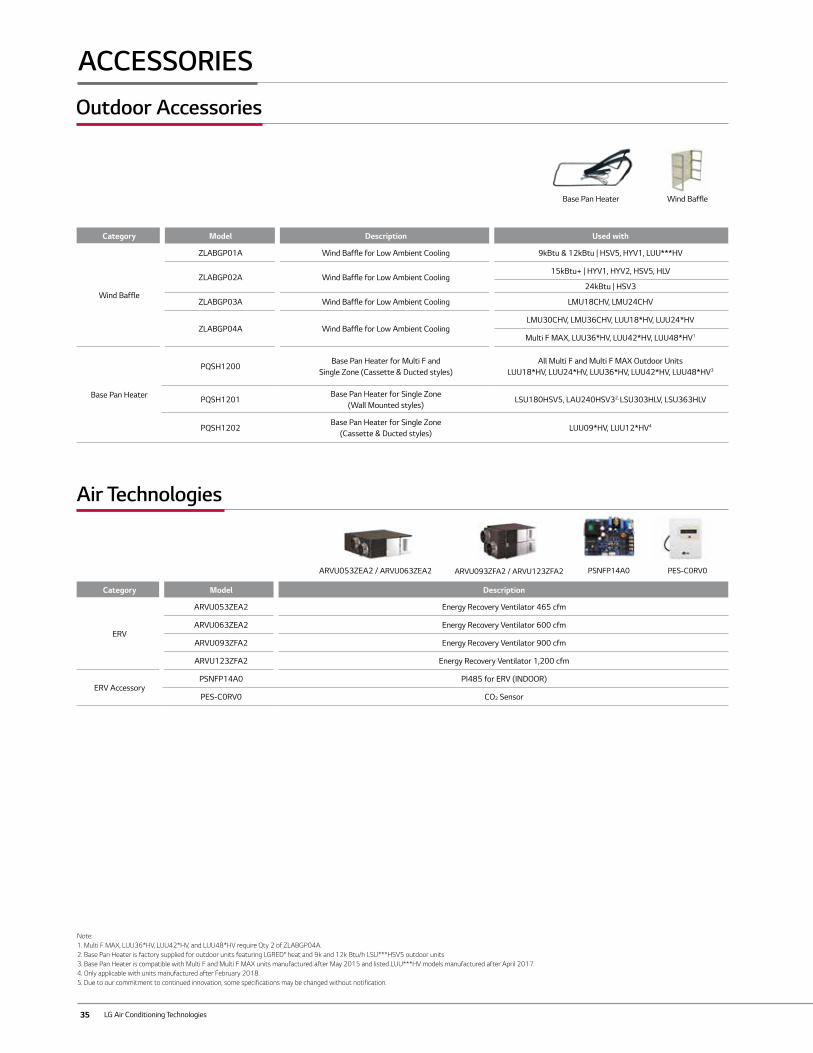
35 LG Air Conditioning Technologies
Category Model Description
ERV
ARVU053ZEA2 Energy Recovery Ventilator 465 cfm
ARVU063ZEA2 Energy Recovery Ventilator 600 cfm
ARVU093ZFA2 Energy Recovery Ventilator 900 cfm
ARVU123ZFA2 Energy Recovery Ventilator 1,200 cfm
ERV AccessoryPSNFP14A0 PI485 for ERV (INDOOR)
PES-C0RV0 CO2 Sensor
Outdoor Accessories
PSNFP14A0 PES-C0RV0
Wind BaffleBase Pan Heater
Note:1. Multi F MAX, LUU36*HV, LUU42*HV, and LUU48*HV require Qty 2 of ZLABGP04A.2. Base Pan Heater is factory supplied for outdoor units featuring LGRED° heat and 9k and 12k Btu/h LSU***HSV5 outdoor units3. Base Pan Heater is compatible with Multi F and Multi F MAX units manufactured after May 2015 and listed LUU***HV models manufactured after April 2017.4. Only applicable with units manufactured after February 2018.5. Due to our commitment to continued innovation, some specifications may be changed without notification.
Category Model Description Used with
Wind Baffle
ZLABGP01A Wind Baffle for Low Ambient Cooling 9kBtu & 12kBtu | HSV5, HYV1, LUU***HV
ZLABGP02A Wind Baffle for Low Ambient Cooling15kBtu+ | HYV1, HYV2, HSV5, HLV
24kBtu | HSV3
ZLABGP03A Wind Baffle for Low Ambient Cooling LMU18CHV, LMU24CHV
ZLABGP04A Wind Baffle for Low Ambient CoolingLMU30CHV, LMU36CHV, LUU18*HV, LUU24*HV
Multi F MAX, LUU36*HV, LUU42*HV, LUU48*HV1
Base Pan Heater
PQSH1200Base Pan Heater for Multi F and
Single Zone (Cassette & Ducted styles)All Multi F and Multi F MAX Outdoor Units
LUU18*HV, LUU24*HV, LUU36*HV, LUU42*HV, LUU48*HV3
PQSH1201Base Pan Heater for Single Zone
(Wall Mounted styles)LSU180HSV5, LAU240HSV32, LSU303HLV, LSU363HLV
PQSH1202Base Pan Heater for Single Zone
(Cassette & Ducted styles)LUU09*HV, LUU12*HV4
Air Technologies
ARVU053ZEA2 / ARVU063ZEA2 ARVU093ZFA2 / ARVU123ZFA2
ACCESSORIES
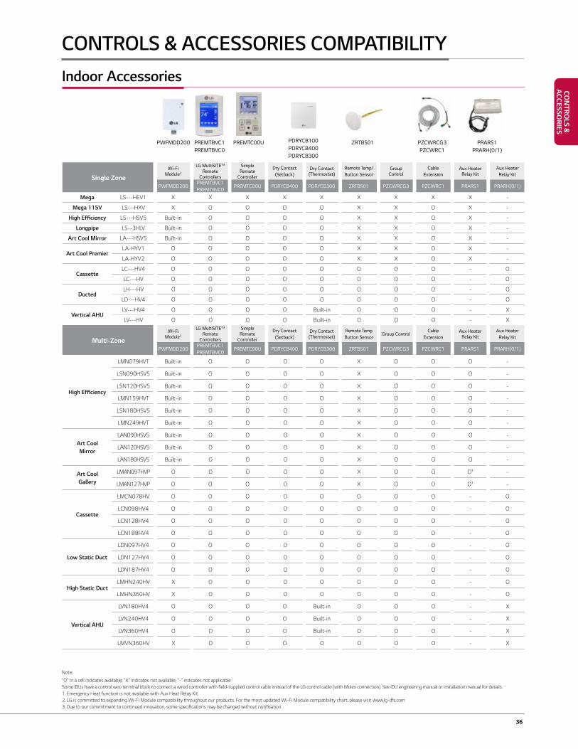
36
Single ZoneWi-Fi
Module3
LG MultiSITE™ Remote
Controllers
Simple Remote
Controller
Dry Contact (Setback)
Dry Contact (Thermostat)
Remote Temp/Button Sensor
Group Control
Cable Extension
Aux Heater Relay Kit
Aux Heater Relay Kit
PWFMDD200PREMTBVC1PREMTBVC0
PREMTC00U PDRYCB400 PDRYCB300 ZRTBS01 PZCWRCG3 PZCWRC1 PRARS1 PRARH(0/1)
Mega LS---HEV1 X X X X X X X X X -
Mega 115V LS---HXV X O O O O X X O X -
High Efficiency LS---HSV5 Built-in O O O O X X O X -
Longpipe LS--3HLV Built-in O O O O X X O X -
Art Cool Mirror LA---HSV5 Built-in O O O O X X O X -
Art Cool PremierLA-HYV1 O O O O O X X O X -
LA-HYV2 O O O O O X X O X -
CassetteLC---HV4 O O O O O O O O - O
LC---HV O O O O O O O O - O
DuctedLH---HV O O O O O O O O - O
LD---HV4 O O O O O O O O - O
Vertical AHULV---HV4 O O O O Built-in O O O - X
LV---HV O O O O Built-in O O O - X
Multi-ZoneWi-Fi
Module3
LG MultiSITE™ Remote
Controllers
Simple Remote
Controller
Dry Contact (Setback)
Dry Contact (Thermostat)
Remote Temp Button Sensor
Group ControlCable
ExtensionAux Heater
Relay KitAux Heater
Relay Kit
PWFMDD200PREMTBVC1PREMTBVC0
PREMTC00U PDRYCB400 PDRYCB300 ZRTBS01 PZCWRCG3 PZCWRC1 PRARS1 PRARH(0/1)
High Efficiency
LMN079HVT Built-in O O O O X O O O -
LSN090HSV5 Built-in O O O O X O O O -
LSN120HSV5 Built-in O O O O X O O O -
LMN159HVT Built-in O O O O X O O O -
LSN180HSV5 Built-in O O O O X O O O -
LMN249HVT Built-in O O O O X O O O -
Art CoolMirror
LAN090HSV5 Built-in O O O O X O O O -
LAN120HSV5 Built-in O O O O X O O O -
LAN180HSV5 Built-in O O O O X O O O -
Art Cool Gallery
LMAN097HVP O O O O O X O O O1 -
LMAN127HVP O O O O O X O O O1 -
Cassette
LMCN078HV O O O O O O O O - O
LCN098HV4 O O O O O O O O - O
LCN128HV4 O O O O O O O O - O
LCN188HV4 O O O O O O O O - O
Low Static Duct
LDN097HV4 O O O O O O O O - O
LDN127HV4 O O O O O O O O - O
LDN187HV4 O O O O O O O O - O
High Static DuctLMHN240HV X O O O O O O O - O
LMHN360HV X O O O O O O O - O
Vertical AHU
LVN180HV4 O O O O Built-in O O O - X
LVN240HV4 O O O O Built-in O O O - X
LVN360HV4 O O O O Built-in O O O - X
LMVN360HV X O O O O O O O - X
PREMTBVC1PREMTBVC0
PREMTC00U PRARS1PRARH(0/1)
PDRYCB100PDRYCB400PDRYCB300
PZCWRCG3PZCWRC1
PWFMDD200
CONTROLS & ACCESSORIES COMPATIBILITY
ZRTBS01
Note:
“O” in a cell indicates available; “X” indicates not available; “-“ indicates not applicable. Some IDUs have a control wire terminal block to connect a wired controller with field-supplied control cable instead of the LG control cable (with Molex connection). See IDU engineering manual or installation manual for details.1. Emergency Heat function is not available with Aux Heat Relay Kit.2. LG is committed to expanding Wi-Fi Module compatibility throughout our products. For the most updated Wi-Fi Module compatibility chart, please visit www.lg-dfs.com3. Due to our commitment to continued innovation, some specifications may be changed without notification.
Indoor Accessories
CON
TROLS &
ACCESSO
RIES
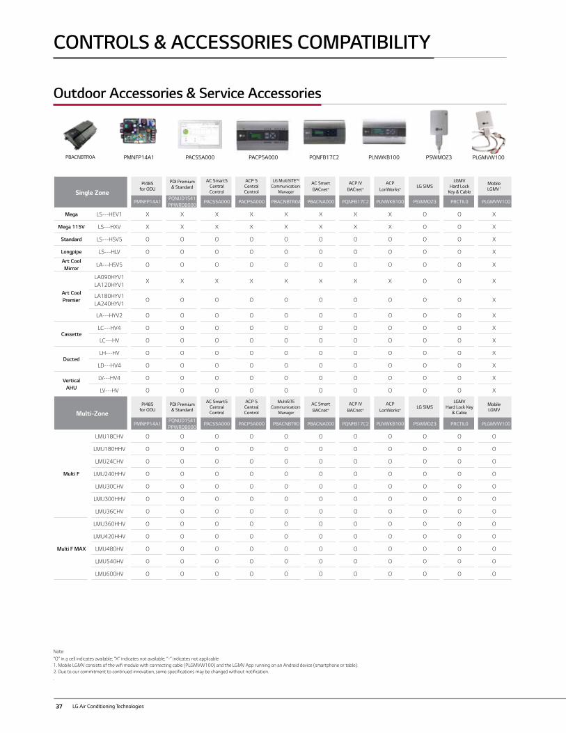
37 LG Air Conditioning Technologies
Outdoor Accessories & Service Accessories
PMNFP14A1 PACS5A000 PACP5A000 PQNFB17C2 PLNWKB100
Single ZonePI485
for ODU
PDI Premium & Standard
AC Smart5 Central Control
ACP 5Central Control
LG MultiSITE™ Communications
Manager
AC Smart BACnet®
ACP IV BACnet®
ACP LonWorks®
LG SIMSLGMV
Hard Lock Key & Cable
Mobile LGMV1
PMNFP14A1PQNUD1S41PPWRDB000
PACS5A000 PACP5A000 PBACNBTR0A PBACNA000 PQNFB17C2 PLNWKB100 PSWMOZ3 PRCTIL0 PLGMVW100
Mega LS---HEV1 X X X X X X X X O O X
Mega 115V LS---HXV X X X X X X X X O O X
Standard LS---HSV5 O O O O O O O O O O X
Longpipe LS---HLV O O O O O O O O O O X
Art Cool Mirror
LA---HSV5 O O O O O O O O O O X
Art Cool Premier
LA090HYV1LA120HYV1
X X X X X X X X O O X
LA180HYV1LA240HYV1
O O O O O O O O O O X
LA---HYV2 O O O O O O O O O O X
CassetteLC---HV4 O O O O O O O O O O X
LC---HV O O O O O O O O O O X
DuctedLH---HV O O O O O O O O O O X
LD---HV4 O O O O O O O O O O X
Vertical AHU
LV---HV4 O O O O O O O O O O X
LV---HV O O O O O O O O O O X
Multi-ZonePI485
for ODUPDI Premium & Standard
AC Smart5 Central Control
ACP 5Central Control
MultiSITE Communications
Manager
AC Smart BACnet®
ACP IV BACnet®
ACP LonWorks®
LG SIMSLGMV
Hard Lock Key & Cable
Mobile LGMV
PMNFP14A1PQNUD1S41PPWRDB000
PACS5A000 PACP5A000 PBACNBTR0 PBACNA000 PQNFB17C2 PLNWKB100 PSWMOZ3 PRCTIL0 PLGMVW100
Multi F
LMU18CHV O O O O O O O O O O O
LMU180HHV O O O O O O O O O O O
LMU24CHV O O O O O O O O O O O
LMU240HHV O O O O O O O O O O O
LMU30CHV O O O O O O O O O O O
LMU300HHV O O O O O O O O O O O
LMU36CHV O O O O O O O O O O O
Multi F MAX
LMU360HHV O O O O O O O O O O O
LMU420HHV O O O O O O O O O O O
LMU480HV O O O O O O O O O O O
LMU540HV O O O O O O O O O O O
LMU600HV O O O O O O O O O O O
CONTROLS & ACCESSORIES COMPATIBILITY
PSWMOZ3
“O” in a cell indicates available; “X” indicates not available; “-“ indicates not applicable1. Mobile LGMV consists of the wifi module with connecting cable (PLGMVW100) and the LGMV App running on an Android device (smartphone or table).2. Due to our commitment to continued innovation, some specifications may be changed without notification..
Note:
PLGMVW100PBACNBTR0A
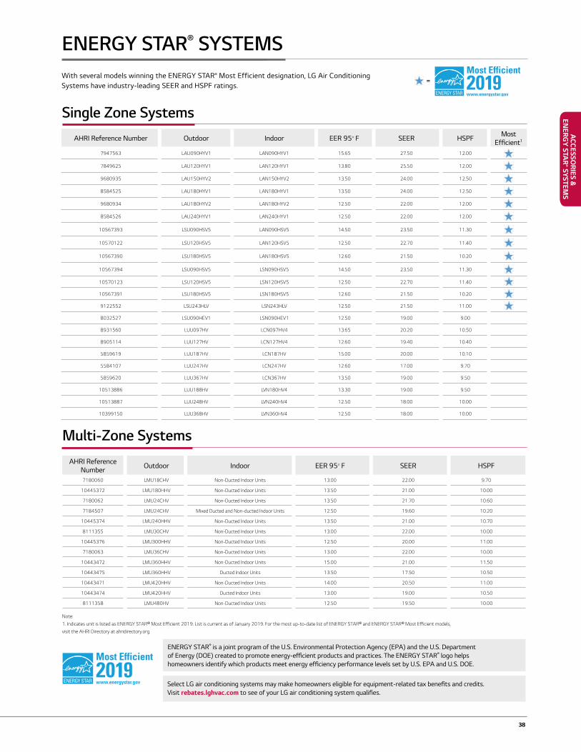
38
AHRI Reference Number Outdoor Indoor EER 95° F SEER HSPF Most Efficient1
7947563 LAU090HYV1 LAN090HYV1 15.65 27.50 12.00
7849625 LAU120HYV1 LAN120HYV1 13.80 25.50 12.00
9680935 LAU150HYV2 LAN150HYV2 13.50 24.00 12.50
8584525 LAU180HYV1 LAN180HYV1 13.50 24.00 12.50
9680934 LAU180HYV2 LAN180HYV2 12.50 22.00 12.00
8584526 LAU240HYV1 LAN240HYV1 12.50 22.00 12.00
10567393 LSU090HSV5 LAN090HSV5 14.50 23.50 11.30
10570122 LSU120HSV5 LAN120HSV5 12.50 22.70 11.40
10567390 LSU180HSV5 LAN180HSV5 12.60 21.50 10.20
10567394 LSU090HSV5 LSN090HSV5 14.50 23.50 11.30
10570123 LSU120HSV5 LSN120HSV5 12.50 22.70 11.40
10567391 LSU180HSV5 LSN180HSV5 12.60 21.50 10.20
9122552 LSU243HLV LSN243HLV 12.50 21.50 11.00
8032527 LSU090HEV1 LSN090HEV1 12.50 19.00 9.00
8931560 LUU097HV LCN097HV4 13.65 20.20 10.50
8905114 LUU127HV LCN127HV4 12.60 19.40 10.40
5859619 LUU187HV LCN187HV 15.00 20.00 10.10
5584107 LUU247HV LCN247HV 12.60 17.00 9.70
5859620 LUU367HV LCN367HV 13.50 19.00 9.50
10513886 LUU188HV LVN180HV4 13.30 19.00 9.50
10513887 LUU248HV LVN240HV4 12.50 18.00 10.00
10399150 LUU368HV LVN360HV4 12.50 18.00 10.00
AHRI Reference Number Outdoor Indoor EER 95° F SEER HSPF
7180060 LMU18CHV Non-Ducted Indoor Units 13.00 22.00 9.70
10445372 LMU180HHV Non-Ducted Indoor Units 13.50 21.00 10.00
7180062 LMU24CHV Non-Ducted Indoor Units 13.50 21.70 10.60
7184507 LMU24CHV Mixed Ducted and Non-ducted Indoor Units 12.50 19.60 10.20
10445374 LMU240HHV Non-Ducted Indoor Units 13.50 21.00 10.70
8111355 LMU30CHV Non-Ducted Indoor Units 13.00 22.00 10.00
10445376 LMU300HHV Non-Ducted Indoor Units 12.50 20.00 11.00
7180063 LMU36CHV Non-Ducted Indoor Units 13.00 22.00 10.00
10443472 LMU360HHV Non-Ducted Indoor Units 15.00 21.00 11.50
10443475 LMU360HHV Ducted Indoor Units 13.50 17.50 10.50
10443471 LMU420HHV Non-Ducted Indoor Units 14.00 20.50 11.00
10443474 LMU420HHV Ducted Indoor Units 13.00 19.00 10.50
8111358 LMU480HV Non-Ducted Indoor Units 12.50 19.50 10.00
Single Zone Systems
Multi-Zone Systems
ENERGY STAR® is a joint program of the U.S. Environmental Protection Agency (EPA) and the U.S. Department of Energy (DOE) created to promote energy-efficient products and practices. The ENERGY STAR® logo helps homeowners identify which products meet energy efficiency performance levels set by U.S. EPA and U.S. DOE.
Select LG air conditioning systems may make homeowners eligible for equipment-related tax benefits and credits. Visit rebates.lghvac.com to see of your LG air conditioning system qualifies.
Note:1. Indicates unit is listed as ENERGY STAR® Most Efficient 2019. List is current as of January 2019. For the most up-to-date list of ENERGY STAR® and ENERGY STAR® Most Efficient models, visit the AHRI Directory at ahridirectory.org.
=
ENERGY STAR® SYSTEMSWith several models winning the ENERGY STAR® Most Efficient designation, LG Air Conditioning Systems have industry-leading SEER and HSPF ratings.
ACCESSO
RIES & EN
ERGY STA
R® SYSTEM
S
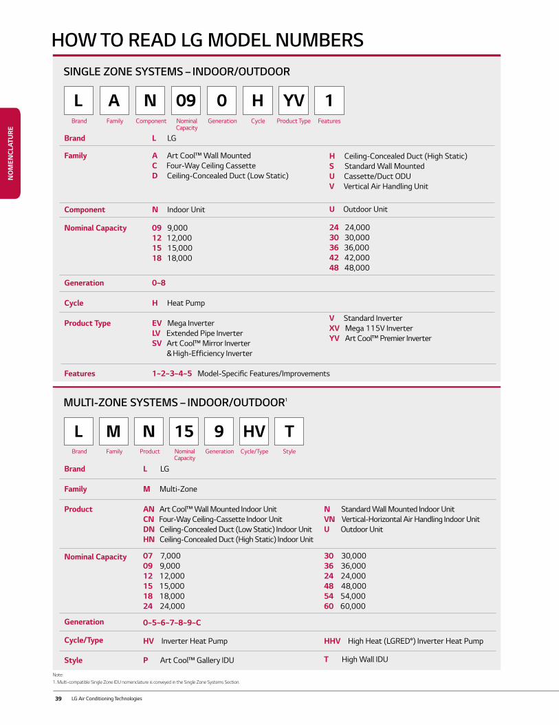
39 LG Air Conditioning Technologies
Note:1. Multi-compatible Single Zone IDU nomenclature is conveyed in the Single Zone Systems Section.
HOW TO READ LG MODEL NUMBERSSINGLE ZONE SYSTEMS – INDOOR/OUTDOOR
MULTI-ZONE SYSTEMS – INDOOR/OUTDOOR1
L
L
A
M
N
N
H
HV
09
15
YV
T
0
9
1Brand
Brand
Family
Family
Component
Product
Nominal Capacity
Nominal Capacity
Generation
Generation
Cycle
Cycle/Type
Product Type
Style
Features
Brand
Family
Component
Nominal Capacity
Generation
Cycle
Product Type
Features
Brand
Family
Product
Nominal Capacity
Generation
Cycle/Type
Style
L LG
A Art Cool™ Wall MountedC Four-Way Ceiling CassetteD Ceiling-Concealed Duct (Low Static)
N Indoor Unit
09 9,00012 12,000 15 15,00018 18,000
0~8
H Heat Pump
EV Mega Inverter LV Extended Pipe Inverter SV Art Cool™ Mirror Inverter & High-Efficiency Inverter
1~2~3~4~5 Model-Specific Features/Improvements
L LG
M Multi-Zone
AN Art Cool™ Wall Mounted Indoor Unit CN Four-Way Ceiling-Cassette Indoor UnitDN Ceiling-Concealed Duct (Low Static) Indoor Unit HN Ceiling-Concealed Duct (High Static) Indoor Unit
07 7,00009 9,000 12 12,00015 15,000 18 18,000 24 24,000
0~5~6~7~8~9~C
HV Inverter Heat Pump P Art Cool™ Gallery IDU
N Standard Wall Mounted Indoor Unit VN Vertical-Horizontal Air Handling Indoor UnitU Outdoor Unit
30 30,00036 36,00024 24,000 48 48,00054 54,00060 60,000
HHV High Heat (LGRED°) Inverter Heat Pump
T High Wall IDU
H Ceiling-Concealed Duct (High Static)S Standard Wall MountedU Cassette/Duct ODUV Vertical Air Handling Unit
U Outdoor Unit
24 24,00030 30,000 36 36,00042 42,00048 48,000
V Standard Inverter XV Mega 115V Inverter YV Art Cool™ Premier Inverter
NO
MEN
CLAT
URE
40
NOTES
41 LG Air Conditioning Technologies
NOTES

42
NOTES
Distributed byLG Electronics USA, Inc.Air Conditioning Technologies4300 North Point Parkway, Alpharetta, GA 30022
www.lghvac.com
©2019 LG Electronics U.S.A. All rights reserved. Document Number: PB_Single_Multi_DFS_Systems_06_19