Embed Size (px)
Citation preview
Respironics V60 VentilatorUser Manual

For Technical Support and Customer Service, contact:USA and Canada: 800-345-6443 or 724-387-4000Respironics Europe, Africa, Middle East: +33-1-47-52-30-00Respironics Asia Pacific: +852-3194-2280Facsimile: +1-724-387-5012
USARespironics California, Inc.2271 Cosmos CourtCarlsbad, CA 92011
Email and web [email protected]@philips.comwww.philips.com\healthcare
Authorized European representativeRespironics Deutschland GmbHGewerbestrasse 17D-82211 HerrschingGermany+49-8-15-29-30-60
1047358 Rev C Respironics V60 Ventilator User Manual iii
Table of contents
1. Warnings, cautions, and notes . . . . . . . . . . . . . . . . . . . . . . . . . . . . . . . 1-1Definitions . . . . . . . . . . . . . . . . . . . . . . . . . . . . . . . . . . . . . . . . . . . . 1-1General. . . . . . . . . . . . . . . . . . . . . . . . . . . . . . . . . . . . . . . . . . . . . . . 1-1Preparing for ventilation . . . . . . . . . . . . . . . . . . . . . . . . . . . . . . . . . . . 1-3Operation . . . . . . . . . . . . . . . . . . . . . . . . . . . . . . . . . . . . . . . . . . . . . 1-5Alarms and messages. . . . . . . . . . . . . . . . . . . . . . . . . . . . . . . . . . . . . 1-5Care and maintenance . . . . . . . . . . . . . . . . . . . . . . . . . . . . . . . . . . . . 1-5First-time installation . . . . . . . . . . . . . . . . . . . . . . . . . . . . . . . . . . . . . 1-6Communications interface . . . . . . . . . . . . . . . . . . . . . . . . . . . . . . . . . 1-7Diagnostic mode . . . . . . . . . . . . . . . . . . . . . . . . . . . . . . . . . . . . . . . . 1-7
2. Symbols . . . . . . . . . . . . . . . . . . . . . . . . . . . . . . . . . . . . . . . . . . . . . . . 2-1
3. General information . . . . . . . . . . . . . . . . . . . . . . . . . . . . . . . . . . . . . . . 3-1Intended use . . . . . . . . . . . . . . . . . . . . . . . . . . . . . . . . . . . . . . . . . . . 3-1About CO2 rebreathing . . . . . . . . . . . . . . . . . . . . . . . . . . . . . . . . . . . . 3-1Potential side effects . . . . . . . . . . . . . . . . . . . . . . . . . . . . . . . . . . . . . 3-1Contraindications. . . . . . . . . . . . . . . . . . . . . . . . . . . . . . . . . . . . . . . . 3-2General description . . . . . . . . . . . . . . . . . . . . . . . . . . . . . . . . . . . . . . 3-2Physical description . . . . . . . . . . . . . . . . . . . . . . . . . . . . . . . . . . . . . . 3-4
Patient circuits, masks/patient interfaces, and accessories . . . . . . . 3-4Ventilator unit . . . . . . . . . . . . . . . . . . . . . . . . . . . . . . . . . . . . . . 3-6Graphical user interface . . . . . . . . . . . . . . . . . . . . . . . . . . . . . . . 3-9
4. Principles of operation. . . . . . . . . . . . . . . . . . . . . . . . . . . . . . . . . . . . . 4-1System operational overview . . . . . . . . . . . . . . . . . . . . . . . . . . . . . . . . 4-1Pneumatic system operation . . . . . . . . . . . . . . . . . . . . . . . . . . . . . . . . 4-2Breath delivery characteristics . . . . . . . . . . . . . . . . . . . . . . . . . . . . . . 4-2
Control variable . . . . . . . . . . . . . . . . . . . . . . . . . . . . . . . . . . . . . 4-2Triggering, cycling, and leak adaptation . . . . . . . . . . . . . . . . . . . . 4-2Baseline pressure . . . . . . . . . . . . . . . . . . . . . . . . . . . . . . . . . . . . 4-2Pressure rise time . . . . . . . . . . . . . . . . . . . . . . . . . . . . . . . . . . . . 4-3Negative pressures . . . . . . . . . . . . . . . . . . . . . . . . . . . . . . . . . . . 4-3Oxygen concentration . . . . . . . . . . . . . . . . . . . . . . . . . . . . . . . . . 4-3
Auto-Trak Sensitivity . . . . . . . . . . . . . . . . . . . . . . . . . . . . . . . . . . . . . 4-3Triggering . . . . . . . . . . . . . . . . . . . . . . . . . . . . . . . . . . . . . . . . . . 4-3Cycling . . . . . . . . . . . . . . . . . . . . . . . . . . . . . . . . . . . . . . . . . . . 4-3Leak adaptation . . . . . . . . . . . . . . . . . . . . . . . . . . . . . . . . . . . . . 4-5
Ventilation modes . . . . . . . . . . . . . . . . . . . . . . . . . . . . . . . . . . . . . . . 4-7CPAP mode . . . . . . . . . . . . . . . . . . . . . . . . . . . . . . . . . . . . . . . . 4-8PCV mode . . . . . . . . . . . . . . . . . . . . . . . . . . . . . . . . . . . . . . . . . 4-9S/T mode . . . . . . . . . . . . . . . . . . . . . . . . . . . . . . . . . . . . . . . . . 4-10AVAPS mode (optional) . . . . . . . . . . . . . . . . . . . . . . . . . . . . . . . 4-11
iv Respironics V60 Ventilator User Manual 1047358 Rev C
5. Preparing for ventilation . . . . . . . . . . . . . . . . . . . . . . . . . . . . . . . . . . . 5-1Connecting external devices . . . . . . . . . . . . . . . . . . . . . . . . . . . . . . . . . 5-1Connecting oxygen. . . . . . . . . . . . . . . . . . . . . . . . . . . . . . . . . . . . . . . . 5-1Installing the patient circuit . . . . . . . . . . . . . . . . . . . . . . . . . . . . . . . . . 5-2Connecting to AC power . . . . . . . . . . . . . . . . . . . . . . . . . . . . . . . . . . . . 5-4About the optional backup battery . . . . . . . . . . . . . . . . . . . . . . . . . . . . . 5-4Starting up the ventilator . . . . . . . . . . . . . . . . . . . . . . . . . . . . . . . . . . . 5-6Shutting down the ventilator . . . . . . . . . . . . . . . . . . . . . . . . . . . . . . . . . 5-6Navigating the graphical user interface . . . . . . . . . . . . . . . . . . . . . . . . . 5-7Preoperational check . . . . . . . . . . . . . . . . . . . . . . . . . . . . . . . . . . . . . . 5-8
Required materials . . . . . . . . . . . . . . . . . . . . . . . . . . . . . . . . . . . . 5-8Procedure . . . . . . . . . . . . . . . . . . . . . . . . . . . . . . . . . . . . . . . . . . 5-8Troubleshooting . . . . . . . . . . . . . . . . . . . . . . . . . . . . . . . . . . . . . . 5-9
Alarm tests . . . . . . . . . . . . . . . . . . . . . . . . . . . . . . . . . . . . . . . . . . . . 5-10Preparation . . . . . . . . . . . . . . . . . . . . . . . . . . . . . . . . . . . . . . . . 5-10High Inspiratory Pressure . . . . . . . . . . . . . . . . . . . . . . . . . . . . . . . 5-10Low Tidal Volume . . . . . . . . . . . . . . . . . . . . . . . . . . . . . . . . . . . . 5-10Patient Disconnect . . . . . . . . . . . . . . . . . . . . . . . . . . . . . . . . . . . 5-11Patient Circuit Occluded . . . . . . . . . . . . . . . . . . . . . . . . . . . . . . . 5-11
6. Operation . . . . . . . . . . . . . . . . . . . . . . . . . . . . . . . . . . . . . . . . . . . . . . 6-1Changing the mode . . . . . . . . . . . . . . . . . . . . . . . . . . . . . . . . . . . . . . . 6-2Changing control settings . . . . . . . . . . . . . . . . . . . . . . . . . . . . . . . . . . . 6-3
Making batch setting changes . . . . . . . . . . . . . . . . . . . . . . . . . . . . 6-3Changing individual ventilator settings . . . . . . . . . . . . . . . . . . . . . . 6-4
Using the Ramp Time function . . . . . . . . . . . . . . . . . . . . . . . . . . . . . . . 6-5Changing alarm settings . . . . . . . . . . . . . . . . . . . . . . . . . . . . . . . . . . . . 6-6Selecting the mask and exhalation port . . . . . . . . . . . . . . . . . . . . . . . . . 6-7Running the exhalation port test . . . . . . . . . . . . . . . . . . . . . . . . . . . . . 6-10
Procedure . . . . . . . . . . . . . . . . . . . . . . . . . . . . . . . . . . . . . . . . . 6-10Troubleshooting . . . . . . . . . . . . . . . . . . . . . . . . . . . . . . . . . . . . . 6-11
Other functions: the Menu window . . . . . . . . . . . . . . . . . . . . . . . . . . . 6-11Brightness . . . . . . . . . . . . . . . . . . . . . . . . . . . . . . . . . . . . . . . . . 6-11Loudness . . . . . . . . . . . . . . . . . . . . . . . . . . . . . . . . . . . . . . . . . . 6-11Mask/Port . . . . . . . . . . . . . . . . . . . . . . . . . . . . . . . . . . . . . . . . . 6-11Vent Info (ventilator information) . . . . . . . . . . . . . . . . . . . . . . . . . 6-11Screen Lock . . . . . . . . . . . . . . . . . . . . . . . . . . . . . . . . . . . . . . . . 6-12
Standby . . . . . . . . . . . . . . . . . . . . . . . . . . . . . . . . . . . . . . . . . . . . . . 6-12Help function . . . . . . . . . . . . . . . . . . . . . . . . . . . . . . . . . . . . . . . . . . 6-14Table of modes and control settings . . . . . . . . . . . . . . . . . . . . . . . . . . 6-15
7. Patient monitoring. . . . . . . . . . . . . . . . . . . . . . . . . . . . . . . . . . . . . . . . 7-1Display conventions . . . . . . . . . . . . . . . . . . . . . . . . . . . . . . . . . . . . . . . 7-1Table of monitored parameters . . . . . . . . . . . . . . . . . . . . . . . . . . . . . . . 7-2Scaling the waveform axes . . . . . . . . . . . . . . . . . . . . . . . . . . . . . . . . . . 7-2Freezing and unfreezing waveforms . . . . . . . . . . . . . . . . . . . . . . . . . . . . 7-3
1047358 Rev C Respironics V60 Ventilator User Manual v
8. Alarms and messages . . . . . . . . . . . . . . . . . . . . . . . . . . . . . . . . . . . . . 8-1Responding to alarms. . . . . . . . . . . . . . . . . . . . . . . . . . . . . . . . . . . . . 8-1Setting alarm loudness. . . . . . . . . . . . . . . . . . . . . . . . . . . . . . . . . . . . 8-4Silencing alarms . . . . . . . . . . . . . . . . . . . . . . . . . . . . . . . . . . . . . . . . 8-5Resetting alarms . . . . . . . . . . . . . . . . . . . . . . . . . . . . . . . . . . . . . . . . 8-5
Manually resetting alarms . . . . . . . . . . . . . . . . . . . . . . . . . . . . . . 8-5Clearing autoreset alarms from the Alarms list . . . . . . . . . . . . . . . . 8-5
Hiding/displaying alarm messages . . . . . . . . . . . . . . . . . . . . . . . . . . . . 8-6Alarms and other messages. . . . . . . . . . . . . . . . . . . . . . . . . . . . . . . . . 8-6
9. Care and maintenance . . . . . . . . . . . . . . . . . . . . . . . . . . . . . . . . . . . . . 9-1Decontamination . . . . . . . . . . . . . . . . . . . . . . . . . . . . . . . . . . . . . . . . 9-1
Ventilator exterior . . . . . . . . . . . . . . . . . . . . . . . . . . . . . . . . . . . . 9-1Touchscreen . . . . . . . . . . . . . . . . . . . . . . . . . . . . . . . . . . . . . . . . 9-2Bacteria filter, patient circuit, and other accessories . . . . . . . . . . . 9-2
Preventive maintenance . . . . . . . . . . . . . . . . . . . . . . . . . . . . . . . . . . . 9-3Replacing the air inlet filter . . . . . . . . . . . . . . . . . . . . . . . . . . . . . 9-4Cleaning or replacing the cooling fan filter . . . . . . . . . . . . . . . . . . 9-5Removing and replacing the battery . . . . . . . . . . . . . . . . . . . . . . . 9-6
Disposal . . . . . . . . . . . . . . . . . . . . . . . . . . . . . . . . . . . . . . . . . . . . . . 9-6Storage . . . . . . . . . . . . . . . . . . . . . . . . . . . . . . . . . . . . . . . . . . . . . . . 9-6Repairs . . . . . . . . . . . . . . . . . . . . . . . . . . . . . . . . . . . . . . . . . . . . . . . 9-6Repacking and shipping . . . . . . . . . . . . . . . . . . . . . . . . . . . . . . . . . . . 9-6
10. Technical specifications . . . . . . . . . . . . . . . . . . . . . . . . . . . . . . . . . . 10-1Control settings . . . . . . . . . . . . . . . . . . . . . . . . . . . . . . . . . . . . . . . . 10-1Patient data . . . . . . . . . . . . . . . . . . . . . . . . . . . . . . . . . . . . . . . . . . 10-2Alarms . . . . . . . . . . . . . . . . . . . . . . . . . . . . . . . . . . . . . . . . . . . . . . 10-3Menu window settings . . . . . . . . . . . . . . . . . . . . . . . . . . . . . . . . . . . 10-3Operator-accessible diagnostic mode functions . . . . . . . . . . . . . . . . . . 10-4Physical characteristics . . . . . . . . . . . . . . . . . . . . . . . . . . . . . . . . . . 10-4Environmental specifications . . . . . . . . . . . . . . . . . . . . . . . . . . . . . . 10-5Pneumatic specifications . . . . . . . . . . . . . . . . . . . . . . . . . . . . . . . . . 10-5Electrical specifications . . . . . . . . . . . . . . . . . . . . . . . . . . . . . . . . . . 10-5Other specifications . . . . . . . . . . . . . . . . . . . . . . . . . . . . . . . . . . . . . 10-6
Appendixes
A. First-time installation . . . . . . . . . . . . . . . . . . . . . . . . . . . . . . . . . . . . . . A-1Unpacking and inspection . . . . . . . . . . . . . . . . . . . . . . . . . . . . . . . . . A-1Mounting the ventilator . . . . . . . . . . . . . . . . . . . . . . . . . . . . . . . . . . . A-2Installing the optional battery . . . . . . . . . . . . . . . . . . . . . . . . . . . . . . . A-3Installing oxygen inlet connector and AC power cord (Outside the USA and
Japan only) . . . . . . . . . . . . . . . . . . . . . . . . . . . . . . . . . . . . . . . . . . A-6Installing the oxygen manifold kit . . . . . . . . . . . . . . . . . . . . . . . . . . . . A-7Configuration and screen calibration . . . . . . . . . . . . . . . . . . . . . . . . . . A-7
vi Respironics V60 Ventilator User Manual 1047358 Rev C
B. Communications interface . . . . . . . . . . . . . . . . . . . . . . . . . . . . . . . . . . B-1RS-232 serial and analog I/O port . . . . . . . . . . . . . . . . . . . . . . . . . . . . B-2
Pinout of connector . . . . . . . . . . . . . . . . . . . . . . . . . . . . . . . . . . . B-2Communications protocol . . . . . . . . . . . . . . . . . . . . . . . . . . . . . . B-3Commands and transmission conventions . . . . . . . . . . . . . . . . . . . B-3
Remote alarm port . . . . . . . . . . . . . . . . . . . . . . . . . . . . . . . . . . . . . . B-12
C. Warranty. . . . . . . . . . . . . . . . . . . . . . . . . . . . . . . . . . . . . . . . . . . . . . . C-1One-year warranty . . . . . . . . . . . . . . . . . . . . . . . . . . . . . . . . . . . . . . . . C-1Warranty limits . . . . . . . . . . . . . . . . . . . . . . . . . . . . . . . . . . . . . . . . . . C-1
D. Parts and accessories . . . . . . . . . . . . . . . . . . . . . . . . . . . . . . . . . . . . . D-1Adult masks . . . . . . . . . . . . . . . . . . . . . . . . . . . . . . . . . . . . . . . . . . . D-1Pediatric masks. . . . . . . . . . . . . . . . . . . . . . . . . . . . . . . . . . . . . . . . . D-3Exhalation ports. . . . . . . . . . . . . . . . . . . . . . . . . . . . . . . . . . . . . . . . . D-3Patient breathing circuits . . . . . . . . . . . . . . . . . . . . . . . . . . . . . . . . . . D-4Bacteria filter . . . . . . . . . . . . . . . . . . . . . . . . . . . . . . . . . . . . . . . . . . D-4Operator maintenance parts . . . . . . . . . . . . . . . . . . . . . . . . . . . . . . . . D-4Other parts . . . . . . . . . . . . . . . . . . . . . . . . . . . . . . . . . . . . . . . . . . . . D-5
E. Regulatory compliance . . . . . . . . . . . . . . . . . . . . . . . . . . . . . . . . . . . . E-1Electromagnetic compatibility (EMC) . . . . . . . . . . . . . . . . . . . . . . . . . . . E-1WEEE recycling directive . . . . . . . . . . . . . . . . . . . . . . . . . . . . . . . . . . . E-1Safety. . . . . . . . . . . . . . . . . . . . . . . . . . . . . . . . . . . . . . . . . . . . . . . . . E-2
F. Diagnostic mode . . . . . . . . . . . . . . . . . . . . . . . . . . . . . . . . . . . . . . . . . F-1Entering the diagnostic mode . . . . . . . . . . . . . . . . . . . . . . . . . . . . . . . . F-1System settings . . . . . . . . . . . . . . . . . . . . . . . . . . . . . . . . . . . . . . . . . . F-3
Language . . . . . . . . . . . . . . . . . . . . . . . . . . . . . . . . . . . . . . . . . . . F-4Date/Time . . . . . . . . . . . . . . . . . . . . . . . . . . . . . . . . . . . . . . . . . . F-6Pressure Units . . . . . . . . . . . . . . . . . . . . . . . . . . . . . . . . . . . . . . . F-7Restore Default Settings . . . . . . . . . . . . . . . . . . . . . . . . . . . . . . . . F-8Software Options . . . . . . . . . . . . . . . . . . . . . . . . . . . . . . . . . . . . . F-9Baud Rate . . . . . . . . . . . . . . . . . . . . . . . . . . . . . . . . . . . . . . . . . F-10
Service . . . . . . . . . . . . . . . . . . . . . . . . . . . . . . . . . . . . . . . . . . . . . . . F-11Significant Event Log . . . . . . . . . . . . . . . . . . . . . . . . . . . . . . . . . F-11
Touchscreen calibration . . . . . . . . . . . . . . . . . . . . . . . . . . . . . . . . . . . F-13Exiting the diagnostic mode . . . . . . . . . . . . . . . . . . . . . . . . . . . . . . . . F-13
Glossary . . . . . . . . . . . . . . . . . . . . . . . . . . . . . . . . . . . . . . . . . . Glossary-1
Index . . . . . . . . . . . . . . . . . . . . . . . . . . . . . . . . . . . . . . . . . . . . . . Index-1
1047358 Rev C Respironics V60 Ventilator User Manual 1-1
Chapter 1. Warnings, cautions, and notes
Before using the Respironics V60 Ventilator on a patient, familiarize yourself with this user manual, particularly the safety considerations listed. Be aware, however, that this manual is a reference only. It is not intended to supersede your institution’s protocol regarding the safe use of assisted ventilation.
Definitions WARNING: Alerts the user to the possibility of injury, death, or other serious adverse reactions associated with the use or misuse of the device.
CAUTION: Alerts the user to the possibility of a problem with the device associated with its use or misuse, such as device malfunction, device failure, damage to the device, or damage to other property.
NOTE: Emphasizes information of particular importance.
General WARNING: An alternative means of ventilation shall be available whenever the ventilator is in use. If a fault is detected in the ventilator, disconnect the patient from it and immediately start ventilation with such a device. The ventilator must be removed from clinical use and serviced by Respironics-authorized service personnel.
WARNING: Use the Respironics V60 Ventilator on spontaneously breathing patients only. It is an assist ventilator and is intended to augment the ventilation of a spontaneously breathing patient. It is not intended to provide the total ventilatory requirements of the patient.
WARNING: We do not recommend you use the Respironics V60 Ventilator on patients who require ventilation at predetermined tidal volumes. The ventilator provides continuous positive airway pressure (CPAP) and positive pressure ventilation (S/T, PCV, and AVAPS) and is indicated for assisted ventilation only. These modes do not provide ventilation with guaranteed tidal volume delivery.
WARNING: We do not recommend you use AVAPS on patients who require rapid and frequent IPAP adjustments to maintain a consistent tidal volume. AVAPS, a volume targeted mode, changes the IPAP setting in order to achieve the target tidal volume. During AVAPS setup, there may be a period of time before the target tidal volume is achieved. AVAPS is ideal for more stabilized patients.
Chapter 1
1-2 Respironics V60 Ventilator User Manual 1047358 Rev C
Warnings, cautions, and notes
WARNING: To reduce the risk of CO2 rebreathing, make sure EPAP pressures and exhalation times are sufficient to clear all exhaled gas through the exhalation port. In noninvasive ventilation continuous air flow through the port flushes exhaled gases from the circuit. The ability to completely exhaust exhaled gas from the circuit depends on the EPAP setting and I:E ratio. Higher tidal volumes further increase the volume of CO2 rebreathed by the patient.
WARNING: To reduce the risk of CO2 rebreathing, monitor the patient for changes in respiratory status at the start of ventilation and with each change in ventilator settings, circuit configuration, or patient condition. Pay attention to ventilator alarms that warn of increased CO2 rebreathing risk.
WARNING: Be aware of the possibility of contamination from patient exhalate being exhausted into the room through the exhalation port.
WARNING: To ensure accuracy of oxygen administration and to monitor for the presence of contamination (incorrect gas connected), use an external oxygen monitor to verify the oxygen concentration in the delivered gas.
WARNING: To reduce the risk of fire, use the ventilator in well-ventilated areas away from flammable anesthetics. Do not use in a hyperbaric chamber or other similarly oxygen-enriched environments. Do not use near an open flame.
WARNING: To reduce the risk of electric shock from liquid entering the device, do not put a container filled with a liquid on the ventilator.
WARNING: To reduce patient risk of hypoxemia, keep free-flowing oxygen away from air inlet of ventilator.
WARNING: The nurse call/remote alarm should be considered a backup to the ventilator’s primary alarm system.
WARNING: To ensure that the alarm will be heard, make sure the alarm loudness is adequate and avoid blocking the alarm speakers beneath the ventilator.
CAUTION: Federal law (USA) restricts this device to sale by or on the order of a physician.
CAUTION: The Respironics V60 Ventilator is designed to operate in the temperature range of 5 to 40 ºC (41 to 104 ºF). To minimize the risk of overheating the device, do not operate adjacent to heaters or other heat sources.
NOTE: The displays shown in this manual may not exactly match what you see on your own ventilator.
NOTE: Pressures are indicated on the ventilator in cmH2O. Millibars and hectopascals (hPa) are used by some institutions instead. Since 1 millibar equals 1 hPa, which equals 1.016 cmH2O, the units may be used interchangeably.
NOTE: The ventilator is not intended for use as an ambulance transport ventilator or as an Automatic Transport Ventilator as described by the American Hospital Association and referenced by the FDA. It is intended to allow the patient to be transported within the hospital setting using a cart to move the ventilator.
NOTE: When attachments or other components or subassemblies are added to the ventilator breathing system, the pressure gradient across the ventilator breathing system, measured with respect to the ventilator outlet, may increase.
Chapter 1
1047358 Rev C Respironics V60 Ventilator User Manual 1-3
Warnings, cautions, and notes
NOTE: To ensure the correct performance of the ventilator and the accuracy of patient data, we recommend you use only Respironics-approved accessories with the ventilator. See Appendix D, “Parts and accessories”.
NOTE: This Respironics V60 Ventilator and its recommended accessories that have patient contact are free of latex.
NOTE: If an alarm persists for no apparent reason, discontinue ventilator use and contact Respironics.
NOTE: If you detect any unexplained changes in the performance or visual displays of the ventilator, discontinue ventilator use and contact Respironics.
NOTE: The Respironics V60 Ventilator does not support automatic record keeping.
Preparing for ventilation
WARNING: Connect the ventilator to an appropriate medical-grade oxygen source only. The source must be able to deliver 100% oxygen regulated to 276 to 600 kPa (40 to 87 psig).
WARNING: To reduce the risk of hypoxia, connect only oxygen to the high-pressure connector at the rear of the ventilator.
WARNING: To reduce the risk of fire, do not use a high-pressure oxygen hose that is worn or contaminated with combustible materials like grease or oil.
WARNING: Always check the status of the oxygen cylinders before using the ventilator during transport.
WARNING: To prevent possible asphyxia and to reduce the risk of CO2 rebreathing, take these precautions with respect to mask and exhalation port use:
- Use only a mask with an exhalation port or a nasal mask for noninvasive ventilation.
- Do not occlude the exhalation port.
- Turn on the ventilator and verify that the port is operational before application. Pressurized gas from the ventilator should cause a continuous flow of air to exhaust from the leak port, flushing exhaled gas from the circuit.
- Never leave the mask on the patient while the ventilator is not operating. When the ventilator is not operating, the exhalation port does not allow sufficient exhaust to eliminate CO2 from the circuit. Substantial CO2 rebreathing may occur.
WARNING: To ensure normal air circulation and exchange, do not cover or block the ports on the ventilator or ventilator circuit. Do not block the air inlet panel on the right side of the ventilator.
WARNING: To prevent possible patient injury and possible water damage to the ventilator, make sure the humidifier is set to appropriate temperature and humidification settings.
Chapter 1
1-4 Respironics V60 Ventilator User Manual 1047358 Rev C
Warnings, cautions, and notes
WARNING: To prevent the possibility of inadequate humidification, pay close attention to the humidifier’s functioning when operating the ventilator at an ambient temperature > 30 ºC (86 ºF). The ventilator warms the air delivered to the patient above ambient temperature, which may impair the humidifier’s performance.
WARNING: To reduce the risk that the patient will aspirate condensed water from the breathing circuit, position any humidifier lower than both the ventilator and the patient.
WARNING: To prevent possible patient injury and equipment damage, do not turn the humidifier on until the gas flow has started and is regulated. Starting the heater or leaving it on without gas flow for prolonged periods may result in heat build-up, causing a bolus of hot air to be delivered to the patient. Circuit tubing may melt under these conditions. Turn the heater power switch off before stopping gas flow.
WARNING: To reduce the risk of fire, use only patient circuits intended for use in oxygen-enriched environments. Do not use antistatic or electrically conductive tubing.
WARNING: To prevent patient or ventilator contamination, we recommend you use a Respironics-approved main flow bacteria filter on the patient gas outlet port. Filters not approved by Respironics may degrade system performance.
WARNING: To reduce the risk of bacterial contamination or damage, handle bacteria filters with care.
WARNING: Any additional accessories in the patient circuit may substantially increase flow resistance and impair ventilation.
WARNING: To reduce the risk of strangulation from patient tubing, use a tubing support arm and secure the proximal pressure line with clips.
WARNING: To reduce the risk of electric shock, connect the ventilator to an AC supply mains with protective earth only.
WARNING: Do not use extension cords, adapters, or power cords with the ventilator that are not approved by Respironics.
WARNING: To prevent unintentional disconnection of the power cord, always use the correct, Respironics-supplied power cord and lock it into place with the power cord retainer before you switch the ventilator on. The retainer is designed to hold the connector end of the Respironics-supplied cord securely in place.
WARNING: To reduce the risk of electric shock, regularly inspect the AC power cord and verify that it is not frayed or cracked.
WARNING: To reduce the risk of strangulation, route the power cord to avoid entanglement.
WARNING: To reduce the risk of power failure, pay close attention to the battery’s charge level. The battery’s operation time is approximate and is affected by ventilator settings, discharge and recharge cycles, battery age, and ambient temperature. Battery charge is reduced at low ambient temperatures or in situations where the alarm is continuously sounding.
Chapter 1
1047358 Rev C Respironics V60 Ventilator User Manual 1-5
Warnings, cautions, and notes
WARNING: To ensure the ventilator’s safe operation, always run the full preoperational check described in “Preoperational check” on page 5-8 before using the ventilator on a patient. If the ventilator fails any tests, remove it from clinical use immediately. Do not use the ventilator until necessary repairs are completed and all tests have passed.
WARNING: To prevent possible patient injury, disconnect the patient from the ventilator before running the preoperational check. Make sure another source of ventilatory support is available.
WARNING: To prevent possible patient injury due to nonannunciating alarms, verify the operation of any remote alarm device before use.
WARNING: To prevent possible patient injury, always return alarm settings to hospital-standard values after the preoperational check.
CAUTION: To prevent possible damage to the ventilator, ensure that the connection to the oxygen supply is clean and unlubricated, and that there is no water in the oxygen supply gas.
CAUTION: For 120 V equipment, grounding reliability can only be achieved when it is connected to an equivalent receptacle marked “hospital only” or “hospital grade.”
Operation WARNING: To prevent possible patient injury, avoid setting alarm limits to extreme values, which can render the alarm system useless.
Alarms and messages WARNING: If AC power fails and the backup battery is not installed or is depleted, an audible and visual alarm annunciates for at least 2 minutes. Immediately discontinue ventilator use and secure an alternative means of ventilation. As in most ventilators with passive exhalation ports, when power is lost, sufficient air is not provided through the circuit and exhaled air may be rebreathed.
Care and maintenance
WARNING: To reduce the risk of electric shock, power down the ventilator and disconnect it from AC power before cleaning or servicing it.
WARNING: To prevent patient or ventilator contamination, inspect and replace the main flow bacteria filter between patients and at regular intervals (or as stated by the manufacturer).
WARNING: To prevent possible patient injury, inspect and verify the proper operation of the exhalation port regularly during use.
WARNING: To reduce the risk of fire, explosion, leakage, or other hazard, take these precautions with respect to the battery:
Chapter 1
1-6 Respironics V60 Ventilator User Manual 1047358 Rev C
Warnings, cautions, and notes
- Do not attempt to disassemble, open, drop, crush, bend or deform, insert foreign objects into, puncture, or shred the battery pack; modify or remanufacture it; immerse or expose it to water or other liquids; expose it to fire, excessive heat (including soldering irons); or put it in a microwave oven.
- Replace the battery only with another battery specified by the manufacturer.
- Follow all instructions for proper use of the battery.
- Do not short-circuit the battery or allow metallic or conductive objects to contact the battery connector housing.
- Use the battery with the Respironics V60 Ventilator only.
WARNING: This product consists of devices that may contain mercury, which must be recycled or disposed of in accordance with local, state, or federal laws. (Within this system, the backlight lamps in the monitor display contain mercury.)
CAUTION: Do not attempt to sterilize or autoclave the ventilator.
CAUTION: To prevent possible damage to the ventilator, use only those cleaning agents listed in this manual.
CAUTION: To prevent possible damage to the touchscreen, take care when cleaning it. Do not drip water and/or soap solution. After cleaning and rinsing, remove all moisture with a dry, soft cloth. Never clean the touchscreen with an abrasive brush or device, since this will cause irreparable damage.
CAUTION: To avoid introducing foreign matter into the ventilator and to ensure proper system performance, change the air inlet filter at regular intervals (or as stipulated by your institution).
CAUTION: To ensure proper system performance, use a Respironics-approved air inlet filter.
CAUTION: Because some environments cause a quicker collection of lint and dust than others, inspect the filters more often when needed. The air inlet filter should be replaced; the cooling fan filter should be cleaned.
CAUTION: To prevent possible damage to the ventilator, always ship it with the original packing material. If the original material is not available, contact Respironics to order replacements.
First-time installation WARNING: Never attempt to disconnect or connect the battery during operation.
CAUTION: To prevent possible damage to the ventilator, always secure it to its stand or securely place it on a flat, stable surface that is free of dirt and debris. Do not use the ventilator adjacent to, or stack it with, other equipment.
Chapter 1
1047358 Rev C Respironics V60 Ventilator User Manual 1-7
Warnings, cautions, and notes
Communications interface
WARNING: Connect to the ventilator only items that are specified as part of or compatible with the ventilator system. Additional equipment connected to medical electrical equipment must comply with the respective IEC or ISO standards. Furthermore, all configurations shall comply with the requirements for medical electrical systems (see IEC 60601-1-1 or clause 16 of edition 3 of IEC 60601-1, respectively). Anybody connecting additional equipment to medical electrical equipment configures a medical system and is therefore responsible for ensuring that the system complies with the requirements for medical electrical systems. Also be aware that local laws may take priority over the above mentioned requirements. If in doubt, consult Respironics.
WARNING: It is the responsibility of the end user to validate the compatibility and use of information transmitted from the ventilator to the device to be connected to the ventilator.
WARNING: The data provided through the communications interface is for reference only. Decisions for patient care should be based on the clinician’s observations of the patient.
WARNING: To prevent possible patient injury due to nonannunciating alarms, verify the operation of any remote alarm device before use.
WARNING: To ensure the functionality of the remote alarm, connect only Respironics-approved cables to the remote alarm port.
CAUTION: The remote alarm port is intended to connect only to an SELV (safety extra-low voltage and ungrounded system with basic insulation to ground), in accordance with IEC 60601-1. To prevent damage to the remote alarm, make sure the signal input does not exceed the maximum rating of 24 VAC or 36 VDC at 500 mA with a minimum current of 1 mA.
Diagnostic mode WARNING: To prevent possible patient injury, do not enter the diagnostic mode while a patient is connected to the ventilator. Verify that the patient is disconnected before proceeding.
Chapter 1
1-8 Respironics V60 Ventilator User Manual 1047358 Rev C
Warnings, cautions, and notes
(This page is intentionally blank.)
1047358 Rev C Respironics V60 Ventilator User Manual 2-1
Chapter 2. Symbols
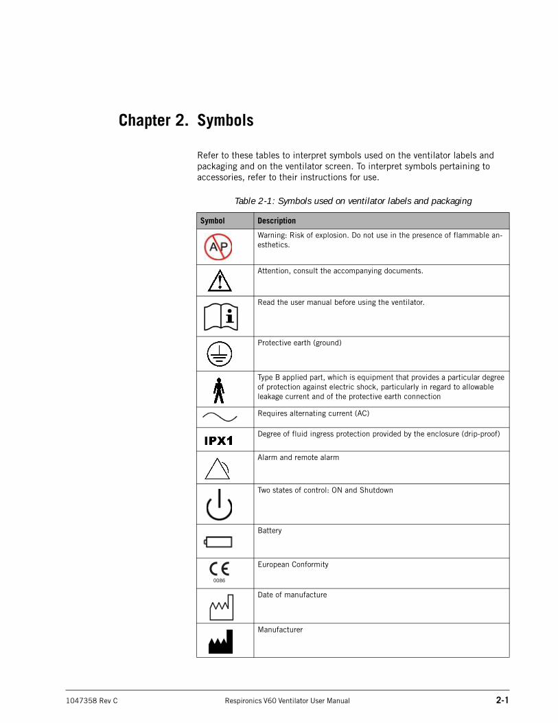
Refer to these tables to interpret symbols used on the ventilator labels and packaging and on the ventilator screen. To interpret symbols pertaining to accessories, refer to their instructions for use.
Table 2-1: Symbols used on ventilator labels and packaging
Symbol Description
Warning: Risk of explosion. Do not use in the presence of flammable an-esthetics.
Attention, consult the accompanying documents.
Read the user manual before using the ventilator.
Protective earth (ground)
Type B applied part, which is equipment that provides a particular degree of protection against electric shock, particularly in regard to allowable leakage current and of the protective earth connection
Requires alternating current (AC)
Degree of fluid ingress protection provided by the enclosure (drip-proof)
Alarm and remote alarm
Two states of control: ON and Shutdown
Battery
European Conformity
Date of manufacture
Manufacturer
Chapter 2
2-2 Respironics V60 Ventilator User Manual 1047358 Rev C
Symbols
RS-232 RS-232 serial input/output
USB port
Oxygen
Ethernet connection
Accept button on the navigation ring
Adjustment direction on the navigation ring
Canadian Standards Association approval
Do not disassemble. Refer to Respironics-authorized service personnel.
Product must be disposed of in accordance with the WEEE directive.
Noninvasive ventilation (patient with mask)
Invasive ventilation (intubated patient)
Do not block the cooling fan Inlet (at the rear of the ventilator).
Hospital-grade
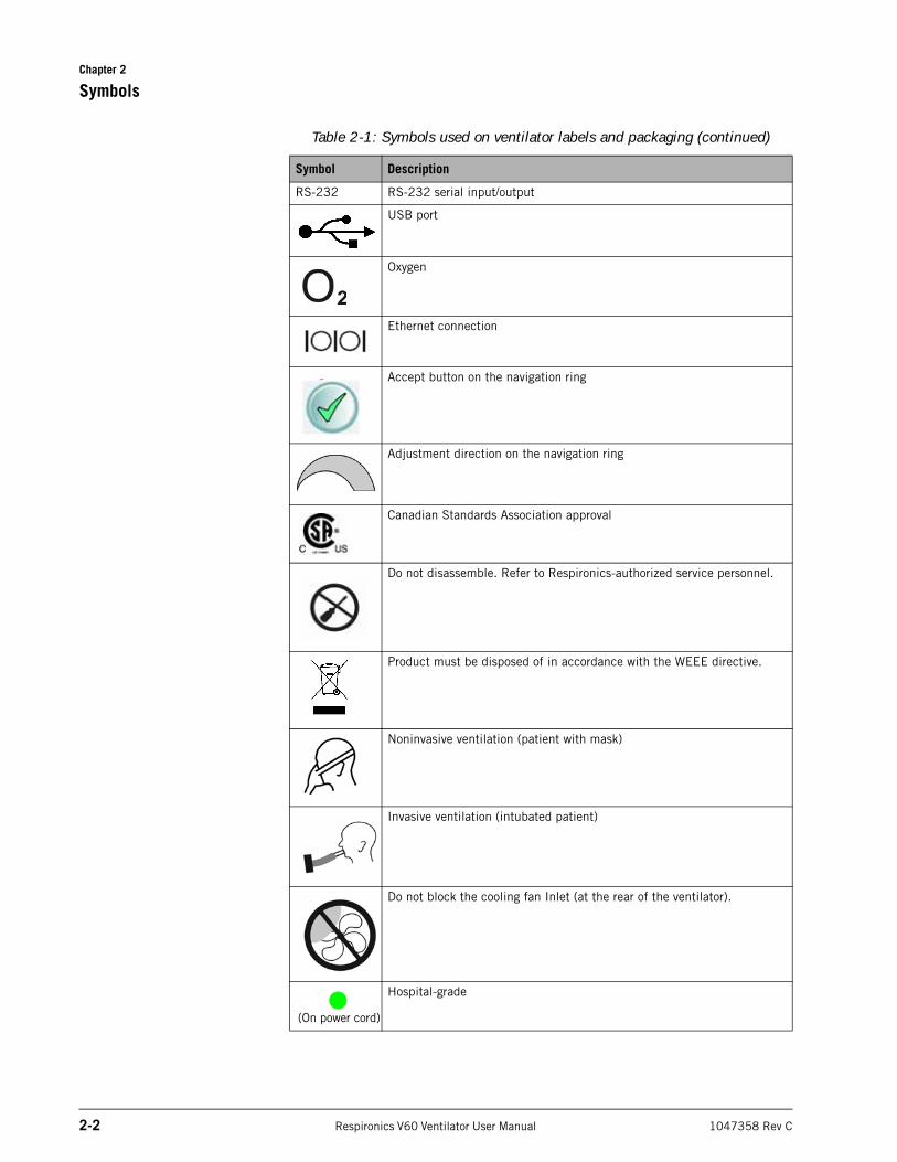
Table 2-1: Symbols used on ventilator labels and packaging (continued)
Symbol Description
(On power cord)
Chapter 2
Symbols
1047358 Rev C Respironics V60 Ventilator User Manual 2-3
This side up
Recycle
Fragile
Keep dry
Do not stack > 3 high
Do not stack > 7 high
Limit temperature to between -20 and 50 ºC (-4 and 122 ºF)
Hazmat class 9
Fire hazard
uR UL recognition symbol
Battery option
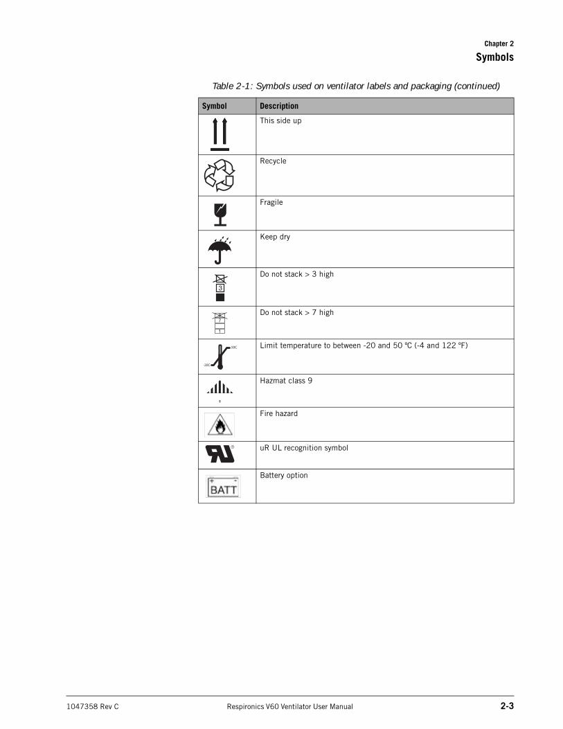
Table 2-1: Symbols used on ventilator labels and packaging (continued)
Symbol Description
3
50C
20C-
Chapter 2
2-4 Respironics V60 Ventilator User Manual 1047358 Rev C
Symbols
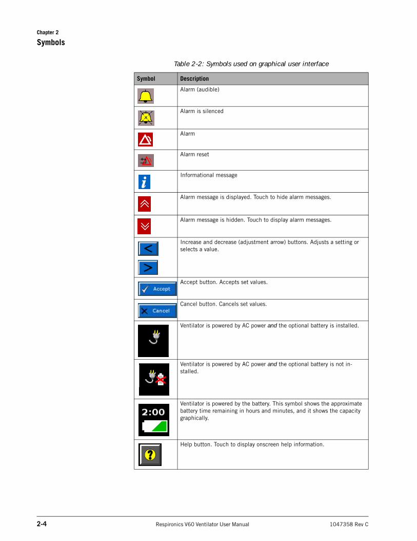
Table 2-2: Symbols used on graphical user interface
Symbol Description
Alarm (audible)
Alarm is silenced
Alarm
Alarm reset
Informational message
Alarm message is displayed. Touch to hide alarm messages.
Alarm message is hidden. Touch to display alarm messages.
Increase and decrease (adjustment arrow) buttons. Adjusts a setting or selects a value.
Accept button. Accepts set values.
Cancel button. Cancels set values.
Ventilator is powered by AC power and the optional battery is installed.
Ventilator is powered by AC power and the optional battery is not in-stalled.
Ventilator is powered by the battery. This symbol shows the approximate battery time remaining in hours and minutes, and it shows the capacity graphically.
Help button. Touch to display onscreen help information.
Chapter 2
Symbols
1047358 Rev C Respironics V60 Ventilator User Manual 2-5
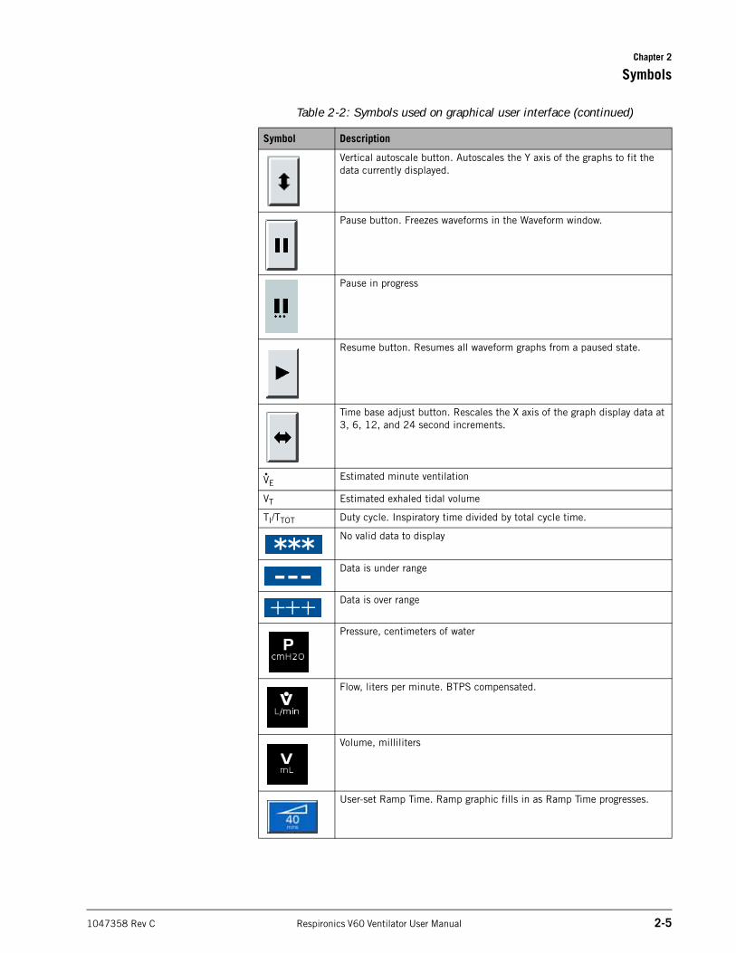
Vertical autoscale button. Autoscales the Y axis of the graphs to fit the data currently displayed.
Pause button. Freezes waveforms in the Waveform window.
Pause in progress
Resume button. Resumes all waveform graphs from a paused state.
Time base adjust button. Rescales the X axis of the graph display data at 3, 6, 12, and 24 second increments.
VEEstimated minute ventilation
VT Estimated exhaled tidal volume
TI/TTOT Duty cycle. Inspiratory time divided by total cycle time.
No valid data to display
Data is under range
Data is over range
Pressure, centimeters of water
Flow, liters per minute. BTPS compensated.
Volume, milliliters
User-set Ramp Time. Ramp graphic fills in as Ramp Time progresses.
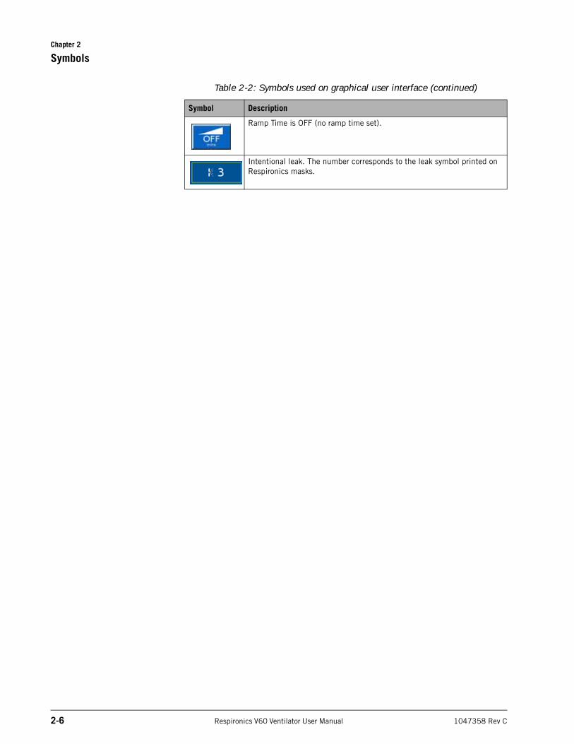
Table 2-2: Symbols used on graphical user interface (continued)
Symbol Description
Chapter 2
2-6 Respironics V60 Ventilator User Manual 1047358 Rev C
Symbols
Ramp Time is OFF (no ramp time set).
Intentional leak. The number corresponds to the leak symbol printed on Respironics masks.
Table 2-2: Symbols used on graphical user interface (continued)
Symbol Description
1047358 Rev C Respironics V60 Ventilator User Manual 3-1
Chapter 3. General information
Intended use The Respironics V60 Ventilator is an assist ventilator and is intended to augment patient breathing. It is intended for spontaneously breathing individuals who require mechanical ventilation: patients with respiratory failure, chronic respiratory insufficiency, or obstructive sleep apnea in a hospital or other institutional settings under the direction of a physician.
The ventilator is intended to support pediatric patients weighing 20 kg (44 lb) or greater to adult patients. It is also intended for intubated patients meeting the same selection criteria as the noninvasive applications. The ventilator is intended to be used by qualified medical professionals, such as physicians, nurses, and respiratory therapists. The ventilator is intended to be used only with various combinations of Respironics-recommended patient circuits, interfaces (masks), humidifiers, and other accessories.
About CO2 rebreathing
As with mask ventilation in general, patient CO2 rebreathing may occur under some circumstances. Follow these guidelines to minimize the potential for CO2 rebreathing. If rebreathing is a significant concern for a particular patient and these guidelines are not sufficient to acceptably reduce the potential for CO2 rebreathing, consider an alternative means of ventilation.
• Increase EPAP to decrease the potential for CO2 rebreathing. Higher pressures produce more flow through the exhalation port, which helps to purge all CO2 from the circuit to prevent rebreathing.
• Be aware that the potential for CO2 rebreathing increases as inspiratory time increases. A longer inspiratory time decreases exhalation time, allowing less CO2 to be purged from the circuit before the next cycle. In such circumstances, higher tidal volumes further increase the volume of CO2 rebreathed by the patient.
Potential side effects Advise the patient to immediately report any unusual chest discomfort, shortness of breath, or severe headache. Other potential side effects of noninvasive positive pressure ventilation include: ear discomfort, conjunctivitis, skin abrasions due to mask/patient interface, and gastric distention (aerophagia). If skin irritation or breakdown develops from the use of the mask, refer to the accompanying mask instructions for appropriate action.
Chapter 3
3-2 Respironics V60 Ventilator User Manual 1047358 Rev C
General information
Contraindications The Respironics V60 Ventilator is contraindicated for patients with any of the following conditions:
• Lack of spontaneous respiratory drive
• Inability to maintain a patent airway or adequately clear secretions
• At risk for aspiration of gastric contents
• Acute sinusitis or otitis media
• Hypotension
• Untreated pertussis
• Epistaxis (nosebleed)
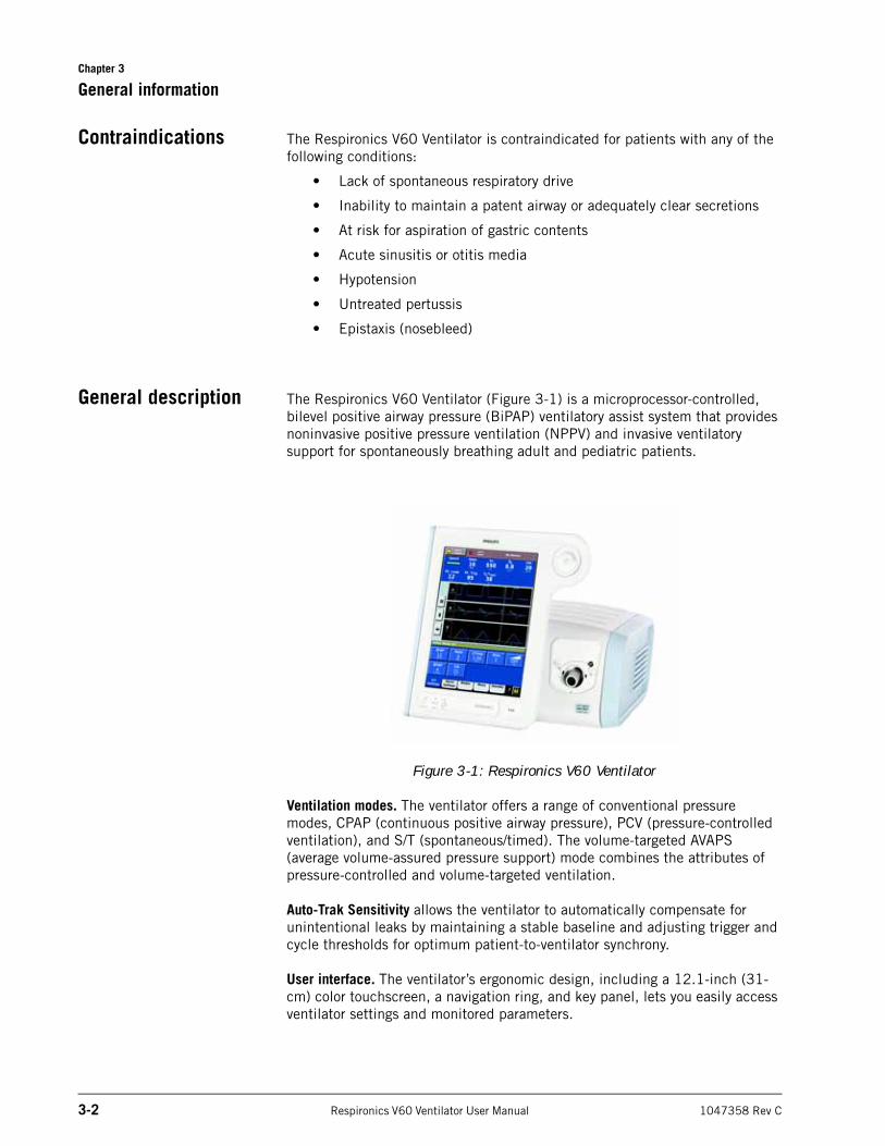
General description The Respironics V60 Ventilator (Figure 3-1) is a microprocessor-controlled, bilevel positive airway pressure (BiPAP) ventilatory assist system that provides noninvasive positive pressure ventilation (NPPV) and invasive ventilatory support for spontaneously breathing adult and pediatric patients.
Figure 3-1: Respironics V60 Ventilator
Ventilation modes. The ventilator offers a range of conventional pressure modes, CPAP (continuous positive airway pressure), PCV (pressure-controlled ventilation), and S/T (spontaneous/timed). The volume-targeted AVAPS (average volume-assured pressure support) mode combines the attributes of pressure-controlled and volume-targeted ventilation.
Auto-Trak Sensitivity allows the ventilator to automatically compensate for unintentional leaks by maintaining a stable baseline and adjusting trigger and cycle thresholds for optimum patient-to-ventilator synchrony.
User interface. The ventilator’s ergonomic design, including a 12.1-inch (31-cm) color touchscreen, a navigation ring, and key panel, lets you easily access ventilator settings and monitored parameters.
Chapter 3
General information
1047358 Rev C Respironics V60 Ventilator User Manual 3-3
Monitoring. The ventilator displays monitored parameters as numbers and as real-time waveforms (curves or scalars).
Alarms. The ventilator’s operator-adjustable and nonadjustable alarms help ensure the patient’s safety.
Power and gas supplies. The ventilator uses as its primary power source AC mains. An optional internal backup battery powers the ventilator typically for 6 hours.
The ventilator uses high-pressure oxygen. An integral blower pressurizes gas for delivery to the patient.
Mounting. The ventilator can be mounted to the universal stand. When equipped with the optional cylinder holder, the stand can accommodate two E-size oxygen cylinders.
Communications interface. The ventilator can output data through the RS-232 serial port upon receiving a command from a host computer or bedside monitoring system. The ventilator is equipped with a remote alarm/nurse call connection to activate alarms remotely.
Upgradability via Respironics Respi-Link remote diagnostic system. The Respi-Link interface permits software upgrade and remote troubleshooting of the ventilator through the RS-232 port.
Chapter 3
3-4 Respironics V60 Ventilator User Manual 1047358 Rev C
General information
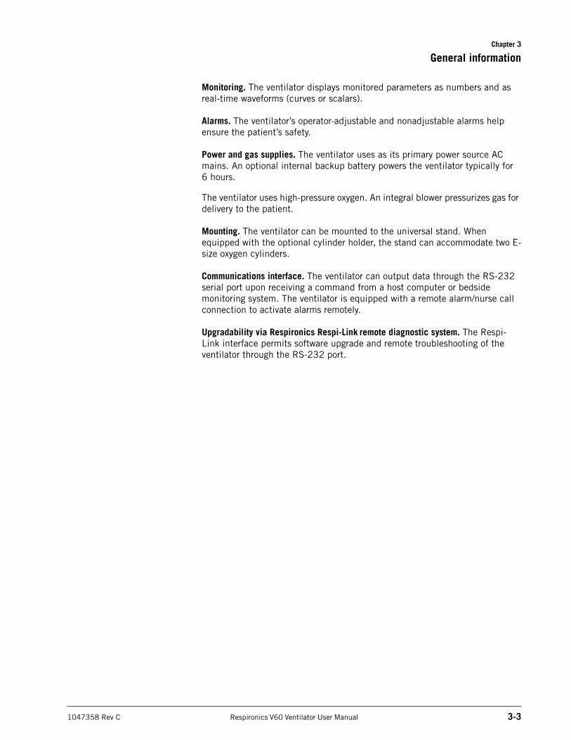
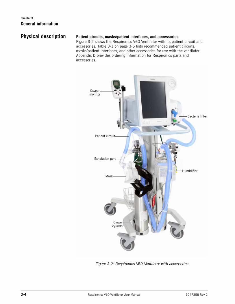
Physical description Patient circuits, masks/patient interfaces, and accessoriesFigure 3-2 shows the Respironics V60 Ventilator with its patient circuit and accessories. Table 3-1 on page 3-5 lists recommended patient circuits,masks/patient interfaces, and other accessories for use with the ventilator. Appendix D provides ordering information for Respironics parts and accessories.
Figure 3-2: Respironics V60 Ventilator with accessories
Oxygenmonitor
Humidifier
Oxygencylinder
Patient circuit
Mask
Bacteria filter
Exhalation port
Chapter 3
General information
1047358 Rev C Respironics V60 Ventilator User Manual 3-5
Table 3-1: Recommended parts and accessories
Part Use...
Patient circuit Single-limb patient circuit intended for noninvasive or invasive ventilation. To mini-mize turbulence, we recommend that you use smooth-bore tubing. Use a Respironics circuit listed in Appendix D or the equiva-lent.
Patient interface (noninvasive or invasive) • Respironics masks listed in Appendix D
• Invasive interface (tracheostomy or ET tube)
Exhalation port Respironics exhalation port listed in Appen-dix D or the equivalent
Inspiratory filter Respironics main flow (inspiratory) bacteria filter listed in Appendix D or the equivalent
Humidifier • Fisher & Paykel MR810 or MR850
• Hudson RCI CONCHATHERM or CONCHATHERM Neptune
Oxygen monitor • CRITERION OxiCheck oxygen analyzer (PN 8-100661-00)
• Teledyne MX300 oxygen monitor
• An equivalent that complies with ISO 7767
Chapter 3
3-6 Respironics V60 Ventilator User Manual 1047358 Rev C
General information
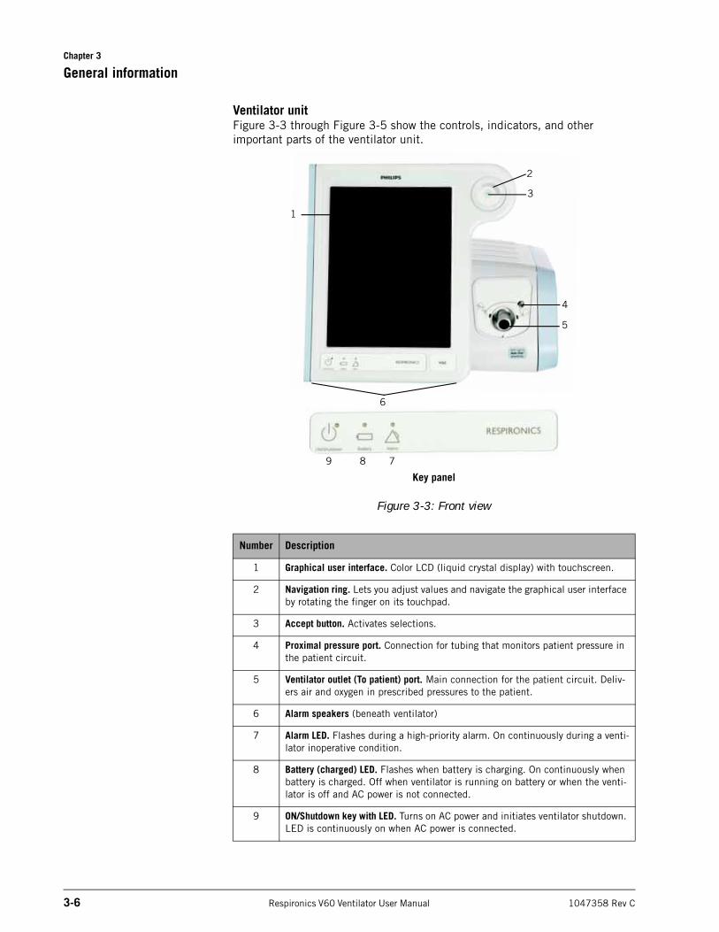
Ventilator unitFigure 3-3 through Figure 3-5 show the controls, indicators, and other important parts of the ventilator unit.
Figure 3-3: Front view
Number Description
1 Graphical user interface. Color LCD (liquid crystal display) with touchscreen.
2 Navigation ring. Lets you adjust values and navigate the graphical user interface by rotating the finger on its touchpad.
3 Accept button. Activates selections.
4 Proximal pressure port. Connection for tubing that monitors patient pressure in the patient circuit.
5 Ventilator outlet (To patient) port. Main connection for the patient circuit. Deliv-ers air and oxygen in prescribed pressures to the patient.
6 Alarm speakers (beneath ventilator)
7 Alarm LED. Flashes during a high-priority alarm. On continuously during a venti-lator inoperative condition.
8 Battery (charged) LED. Flashes when battery is charging. On continuously when battery is charged. Off when ventilator is running on battery or when the venti-lator is off and AC power is not connected.
9 ON/Shutdown key with LED. Turns on AC power and initiates ventilator shutdown. LED is continuously on when AC power is connected.
1
6
5
4
2
3
Key panel
789
Chapter 3
General information
1047358 Rev C Respironics V60 Ventilator User Manual 3-7
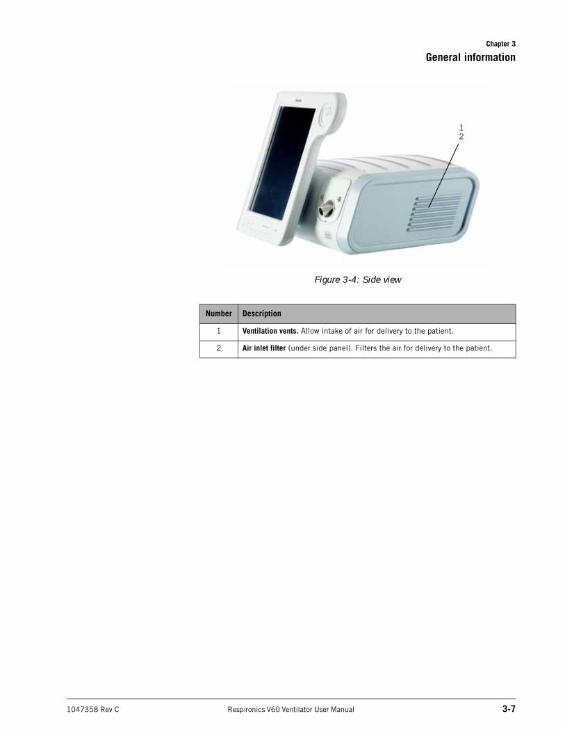
Figure 3-4: Side view
Number Description
1 Ventilation vents. Allow intake of air for delivery to the patient.
2 Air inlet filter (under side panel). Filters the air for delivery to the patient.
12
Chapter 3
3-8 Respironics V60 Ventilator User Manual 1047358 Rev C
General information
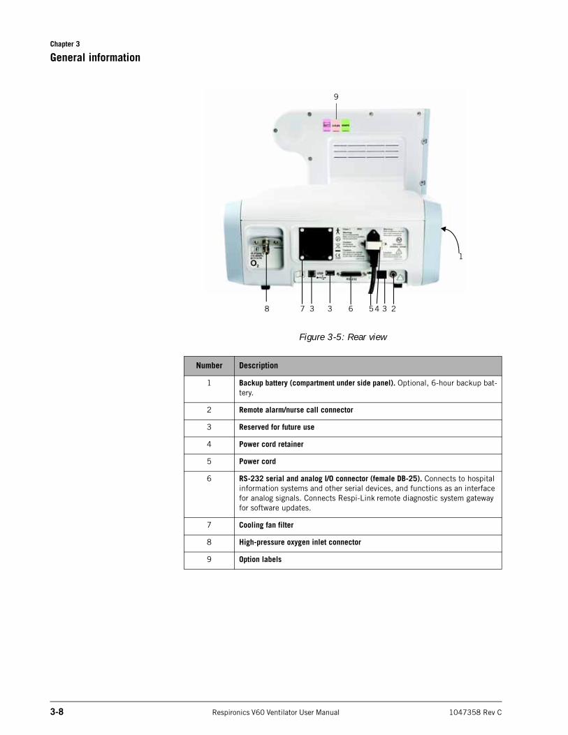
Figure 3-5: Rear view
Number Description
1 Backup battery (compartment under side panel). Optional, 6-hour backup bat-tery.
2 Remote alarm/nurse call connector
3 Reserved for future use
4 Power cord retainer
5 Power cord
6 RS-232 serial and analog I/O connector (female DB-25). Connects to hospital information systems and other serial devices, and functions as an interface for analog signals. Connects Respi-Link remote diagnostic system gateway for software updates.
7 Cooling fan filter
8 High-pressure oxygen inlet connector
9 Option labels
8 3
1
7 3 6 54 3 2
9
Chapter 3
General information
1047358 Rev C Respironics V60 Ventilator User Manual 3-9
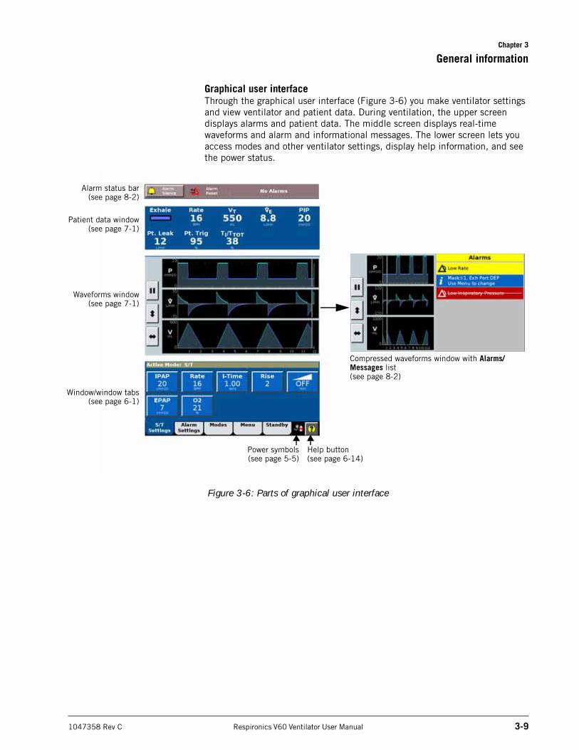
Graphical user interfaceThrough the graphical user interface (Figure 3-6) you make ventilator settings and view ventilator and patient data. During ventilation, the upper screen displays alarms and patient data. The middle screen displays real-time waveforms and alarm and informational messages. The lower screen lets you access modes and other ventilator settings, display help information, and see the power status.
Figure 3-6: Parts of graphical user interface
15
Window/window tabs(see page 6-1)
Help button(see page 6-14)
Waveforms window(see page 7-1)
Patient data window(see page 7-1)
Power symbols(see page 5-5)
Alarm status bar(see page 8-2)
Compressed waveforms window with Alarms/Messages list(see page 8-2)
Chapter 3
3-10 Respironics V60 Ventilator User Manual 1047358 Rev C
General information
(This page is intentionally blank.)
1047358 Rev C Respironics V60 Ventilator User Manual 4-1
Chapter 4. Principles of operation
System operational overview
The Respironics V60 Ventilator is a microprocessor-controlled pneumatic system that delivers a mixture of air and oxygen. It is powered by AC with optional battery backup to protect against power failure or unstable power and to facilitate intrahospital transport. The ventilator’s pneumatics deliver gas and its electrical systems control pneumatics, monitor the patient, and distribute power.
The user provides inputs to the ventilator through a touchscreen, keys, and a navigation ring. These inputs become instructions for the pneumatics to deliver a precisely controlled gas mixture to the patient. Pressure and flow sensors provide feedback, which is used to adjust gas delivery to the patient. Monitored data based on sensor inputs is also displayed by the graphical user interface.
The ventilator’s gas delivery and monitoring functions are cross-checked. This cross-checking helps prevent simultaneous failure of these two main functions and minimizes the possible hazards of system failure.
A comprehensive system of visual and audible alarms helps ensure the patient’s safety. Clinical alarms can indicate an abnormal physiological condition. Technical alarms, triggered by the ventilator’s self-tests, can indicate a hardware or software failure. In the case of some technical alarms, limited ventilation is provided to give the user time for corrective actions. When a condition is critical enough to possibly compromise safe ventilation, the ventilator is placed into the ventilator inoperative state, in which oxygen flow and blower operation are disabled.
The ventilator has several means to ensure that safe patient or respiratory pressures are maintained. The maximum working pressure is ensured by the high inspiratory pressure (HIP) alarm limit. If the set high pressure limit is reached, the ventilator cycles into exhalation.
Chapter 4
4-2 Respironics V60 Ventilator User Manual 1047358 Rev C
Principles of operation
Pneumatic system operation
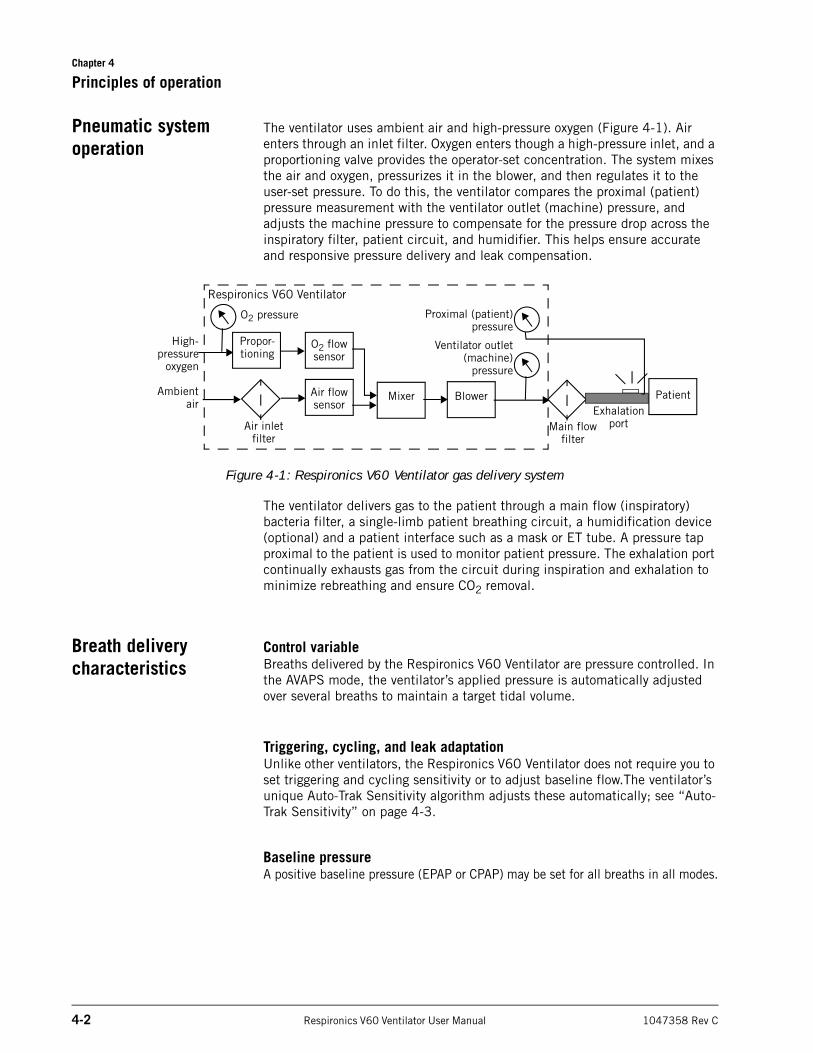
The ventilator uses ambient air and high-pressure oxygen (Figure 4-1). Air enters through an inlet filter. Oxygen enters though a high-pressure inlet, and a proportioning valve provides the operator-set concentration. The system mixes the air and oxygen, pressurizes it in the blower, and then regulates it to the user-set pressure. To do this, the ventilator compares the proximal (patient) pressure measurement with the ventilator outlet (machine) pressure, and adjusts the machine pressure to compensate for the pressure drop across the inspiratory filter, patient circuit, and humidifier. This helps ensure accurate and responsive pressure delivery and leak compensation.
Figure 4-1: Respironics V60 Ventilator gas delivery system
The ventilator delivers gas to the patient through a main flow (inspiratory) bacteria filter, a single-limb patient breathing circuit, a humidification device (optional) and a patient interface such as a mask or ET tube. A pressure tap proximal to the patient is used to monitor patient pressure. The exhalation port continually exhausts gas from the circuit during inspiration and exhalation to minimize rebreathing and ensure CO2 removal.
Breath delivery characteristics
Control variableBreaths delivered by the Respironics V60 Ventilator are pressure controlled. In the AVAPS mode, the ventilator’s applied pressure is automatically adjusted over several breaths to maintain a target tidal volume.
Triggering, cycling, and leak adaptationUnlike other ventilators, the Respironics V60 Ventilator does not require you to set triggering and cycling sensitivity or to adjust baseline flow.The ventilator’s unique Auto-Trak Sensitivity algorithm adjusts these automatically; see “Auto-Trak Sensitivity” on page 4-3.
Baseline pressureA positive baseline pressure (EPAP or CPAP) may be set for all breaths in all modes.
Respironics V60 Ventilator
Blower
High-pressure
oxygen
Ambientair
Proximal (patient)pressure
Ventilator outlet(machine)
pressure
Air flow sensor
Mixer
Propor-tioning
O2 flow sensor
Air inlet filter
Main flow filter
PatientExhalation
port
O2 pressure
Chapter 4
Principles of operation
1047358 Rev C Respironics V60 Ventilator User Manual 4-3
Pressure rise timeThe operator-set Rise Time defines the time required for inspiratory pressure to rise to the set (target) pressure.
Negative pressuresThere are no negative pressures generated during exhalation.
Oxygen concentrationThe Respironics V60 Ventilator incorporates an oxygen mixer. Oxygen concentration can be set in all modes.
Auto-Trak Sensitivity An important characteristic of the Respironics V60 Ventilator is its ability to recognize and compensate for unintentional leaks in the system and to automatically adjust its triggering and cycling algorithms to maintain optimum performance in the presence of leaks. This is called Auto-Trak Sensitivity. The following subsections describe this function in detail.
TriggeringBreaths are patient (flow) triggered in all modes, typically when patient effort causes a certain volume of gas to accumulate above baseline flow (volume method). An inspiration is also triggered when the patient inspiratory effort distorts the expiratory flow waveform sufficiently (shape signal method; see page 4-4).
CyclingCycling to exhalation occurs in these cases:
• Patient expiratory effort distorts the inspiratory flow waveform sufficiently (shape signal method). See “Shape signal method of cycling and triggering.” on page 4-4.
• Patient flow reaches the spontaneous exhalation threshold (SET). See “SET method of cycling.” on page 4-4.
• After 3 seconds at the IPAP level (timed backup safety mechanism)
• When a flow reversal occurs, typically due to a mask or mouth leak
Chapter 4
4-4 Respironics V60 Ventilator User Manual 1047358 Rev C
Principles of operation
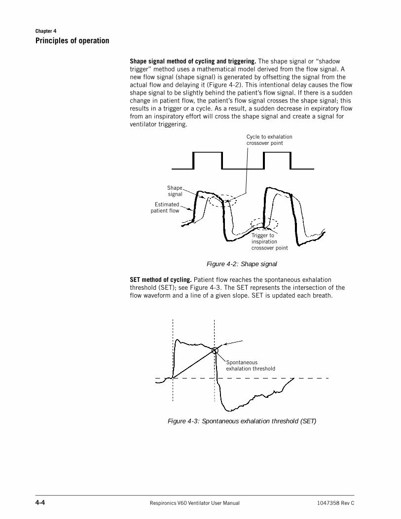
Shape signal method of cycling and triggering. The shape signal or “shadow trigger” method uses a mathematical model derived from the flow signal. A new flow signal (shape signal) is generated by offsetting the signal from the actual flow and delaying it (Figure 4-2). This intentional delay causes the flow shape signal to be slightly behind the patient’s flow signal. If there is a sudden change in patient flow, the patient’s flow signal crosses the shape signal; this results in a trigger or a cycle. As a result, a sudden decrease in expiratory flow from an inspiratory effort will cross the shape signal and create a signal for ventilator triggering.
Figure 4-2: Shape signal
SET method of cycling. Patient flow reaches the spontaneous exhalation threshold (SET); see Figure 4-3. The SET represents the intersection of the flow waveform and a line of a given slope. SET is updated each breath.
Figure 4-3: Spontaneous exhalation threshold (SET)
Estimatedpatient flow
Shapesignal
Cycle to exhalation crossover point
Trigger to inspiration crossover point
Spontaneous exhalation threshold
Chapter 4
Principles of operation
1047358 Rev C Respironics V60 Ventilator User Manual 4-5
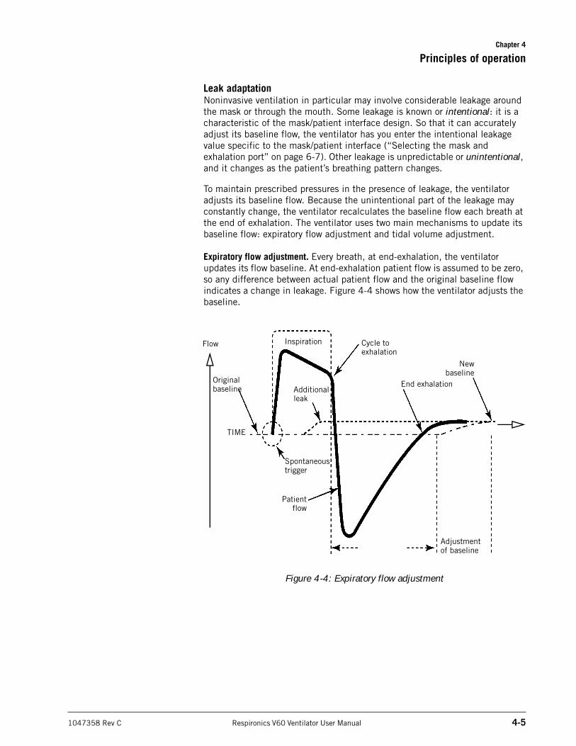
Leak adaptationNoninvasive ventilation in particular may involve considerable leakage around the mask or through the mouth. Some leakage is known or intentional: it is a characteristic of the mask/patient interface design. So that it can accurately adjust its baseline flow, the ventilator has you enter the intentional leakage value specific to the mask/patient interface (“Selecting the mask and exhalation port” on page 6-7). Other leakage is unpredictable or unintentional, and it changes as the patient’s breathing pattern changes.
To maintain prescribed pressures in the presence of leakage, the ventilator adjusts its baseline flow. Because the unintentional part of the leakage may constantly change, the ventilator recalculates the baseline flow each breath at the end of exhalation. The ventilator uses two main mechanisms to update its baseline flow: expiratory flow adjustment and tidal volume adjustment.
Expiratory flow adjustment. Every breath, at end-exhalation, the ventilator updates its flow baseline. At end-exhalation patient flow is assumed to be zero, so any difference between actual patient flow and the original baseline flow indicates a change in leakage. Figure 4-4 shows how the ventilator adjusts the baseline.
Figure 4-4: Expiratory flow adjustment
Flow
TIME
Original baseline
Inspiration
Spontaneous trigger
Cycle to exhalation
End exhalation
Adjustment of baseline
Newbaseline
Patientflow
Additional leak
Chapter 4
4-6 Respironics V60 Ventilator User Manual 1047358 Rev C
Principles of operation
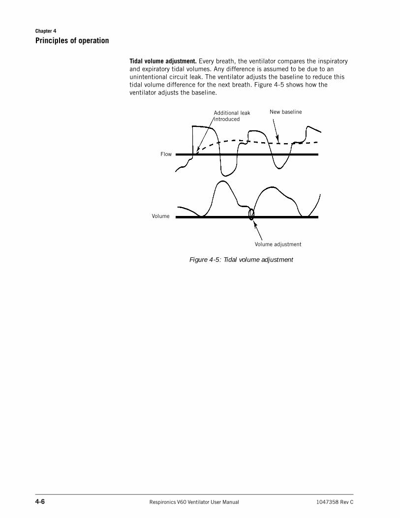
Tidal volume adjustment. Every breath, the ventilator compares the inspiratory and expiratory tidal volumes. Any difference is assumed to be due to an unintentional circuit leak. The ventilator adjusts the baseline to reduce this tidal volume difference for the next breath. Figure 4-5 shows how the ventilator adjusts the baseline.
Figure 4-5: Tidal volume adjustment
Additional leak introduced
New baseline
Volume adjustment
Flow
Volume
Chapter 4
Principles of operation
1047358 Rev C Respironics V60 Ventilator User Manual 4-7
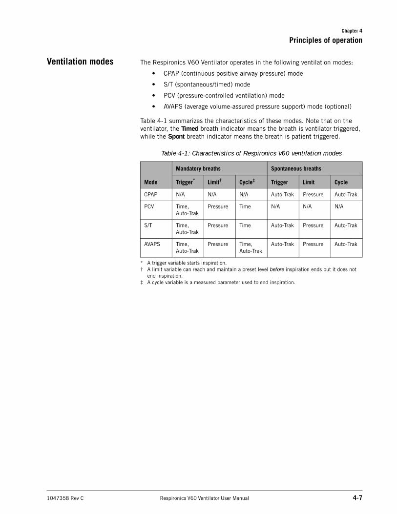
Ventilation modes The Respironics V60 Ventilator operates in the following ventilation modes:
• CPAP (continuous positive airway pressure) mode
• S/T (spontaneous/timed) mode
• PCV (pressure-controlled ventilation) mode
• AVAPS (average volume-assured pressure support) mode (optional)
Table 4-1 summarizes the characteristics of these modes. Note that on the ventilator, the Timed breath indicator means the breath is ventilator triggered, while the Spont breath indicator means the breath is patient triggered.
Table 4-1: Characteristics of Respironics V60 ventilation modes
Mode
Mandatory breaths Spontaneous breaths
Trigger*
* A trigger variable starts inspiration.
Limit†
† A limit variable can reach and maintain a preset level before inspiration ends but it does not end inspiration.
Cycle‡
‡ A cycle variable is a measured parameter used to end inspiration.
Trigger Limit Cycle
CPAP N/A N/A N/A Auto-Trak Pressure Auto-Trak
PCV Time,Auto-Trak
Pressure Time N/A N/A N/A
S/T Time,Auto-Trak
Pressure Time Auto-Trak Pressure Auto-Trak
AVAPS Time,Auto-Trak
Pressure Time,Auto-Trak
Auto-Trak Pressure Auto-Trak
Chapter 4
4-8 Respironics V60 Ventilator User Manual 1047358 Rev C
Principles of operation
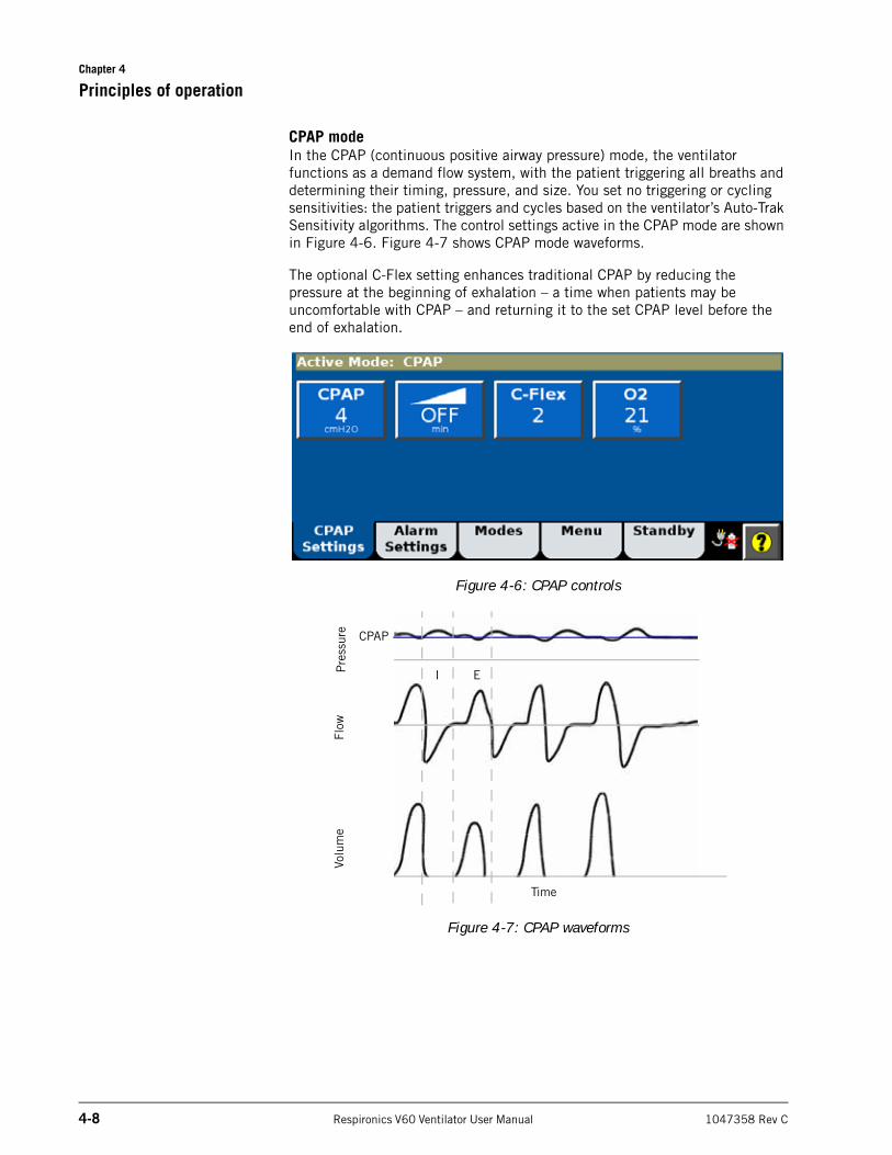
CPAP modeIn the CPAP (continuous positive airway pressure) mode, the ventilator functions as a demand flow system, with the patient triggering all breaths and determining their timing, pressure, and size. You set no triggering or cycling sensitivities: the patient triggers and cycles based on the ventilator’s Auto-Trak Sensitivity algorithms. The control settings active in the CPAP mode are shown in Figure 4-6. Figure 4-7 shows CPAP mode waveforms.
The optional C-Flex setting enhances traditional CPAP by reducing the pressure at the beginning of exhalation – a time when patients may be uncomfortable with CPAP – and returning it to the set CPAP level before the end of exhalation.
Figure 4-6: CPAP controls
Figure 4-7: CPAP waveforms
Volu
me
Flow
Pre
ssur
e
CPAP
I E
Time
Chapter 4
Principles of operation
1047358 Rev C Respironics V60 Ventilator User Manual 4-9
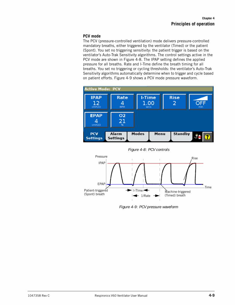
PCV modeThe PCV (pressure-controlled ventilation) mode delivers pressure-controlled mandatory breaths, either triggered by the ventilator (Timed) or the patient (Spont). You set no triggering sensitivity: the patient trigger is based on the ventilator’s Auto-Trak Sensitivity algorithms. The control settings active in the PCV mode are shown in Figure 4-8. The IPAP setting defines the applied pressure for all breaths. Rate and I-Time define the breath timing for all breaths. You set no triggering or cycling thresholds: the ventilator’s Auto-Trak Sensitivity algorithms automatically determine when to trigger and cycle based on patient efforts. Figure 4-9 shows a PCV mode pressure waveform.
Figure 4-8: PCV controls
Figure 4-9: PCV pressure waveform
Pressure
EPAP
IPAP
I-TIme
1/RateMachine-triggered (Timed) breath
Rise
TimePatient-triggered (Spont) breath
Chapter 4
4-10 Respironics V60 Ventilator User Manual 1047358 Rev C
Principles of operation
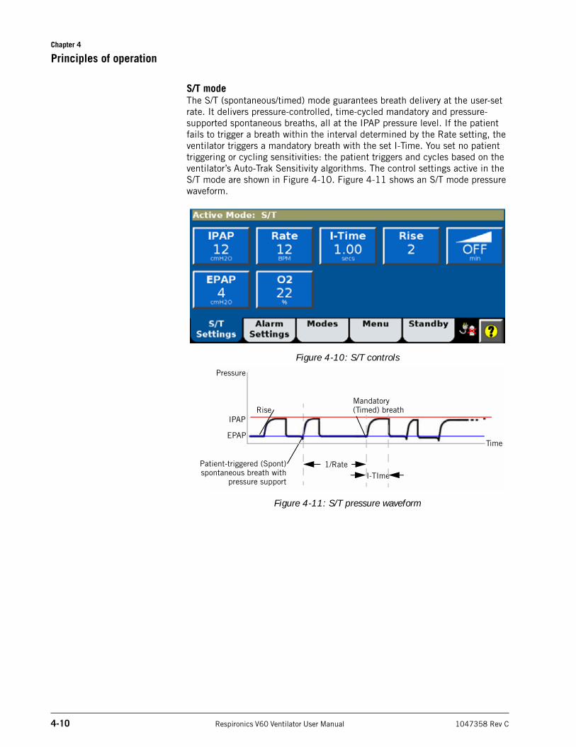
S/T modeThe S/T (spontaneous/timed) mode guarantees breath delivery at the user-set rate. It delivers pressure-controlled, time-cycled mandatory and pressure-supported spontaneous breaths, all at the IPAP pressure level. If the patient fails to trigger a breath within the interval determined by the Rate setting, the ventilator triggers a mandatory breath with the set I-Time. You set no patient triggering or cycling sensitivities: the patient triggers and cycles based on the ventilator’s Auto-Trak Sensitivity algorithms. The control settings active in the S/T mode are shown in Figure 4-10. Figure 4-11 shows an S/T mode pressure waveform.
Figure 4-10: S/T controls
Figure 4-11: S/T pressure waveform
Pressure
EPAP
IPAP
I-TIme1/RatePatient-triggered (Spont)
spontaneous breath withpressure support
Mandatory (Timed) breath
Time
Rise
Chapter 4
Principles of operation
1047358 Rev C Respironics V60 Ventilator User Manual 4-11
AVAPS mode (optional)
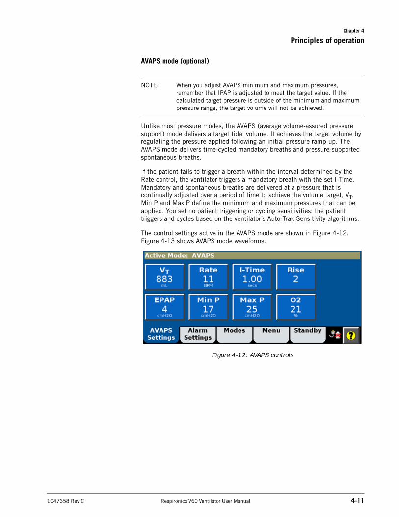
NOTE: When you adjust AVAPS minimum and maximum pressures, remember that IPAP is adjusted to meet the target value. If the calculated target pressure is outside of the minimum and maximum pressure range, the target volume will not be achieved.
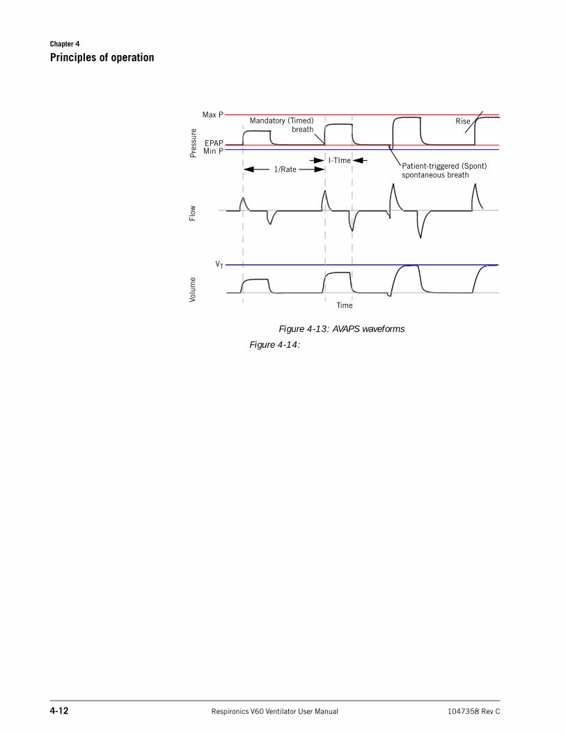
Unlike most pressure modes, the AVAPS (average volume-assured pressure support) mode delivers a target tidal volume. It achieves the target volume by regulating the pressure applied following an initial pressure ramp-up. The AVAPS mode delivers time-cycled mandatory breaths and pressure-supported spontaneous breaths.
If the patient fails to trigger a breath within the interval determined by the Rate control, the ventilator triggers a mandatory breath with the set I-Time. Mandatory and spontaneous breaths are delivered at a pressure that is continually adjusted over a period of time to achieve the volume target, VT. Min P and Max P define the minimum and maximum pressures that can be applied. You set no patient triggering or cycling sensitivities: the patient triggers and cycles based on the ventilator’s Auto-Trak Sensitivity algorithms.
The control settings active in the AVAPS mode are shown in Figure 4-12. Figure 4-13 shows AVAPS mode waveforms.
Figure 4-12: AVAPS controls
Chapter 4
4-12 Respironics V60 Ventilator User Manual 1047358 Rev C
Principles of operation
Figure 4-13: AVAPS waveforms
Figure 4-14:
Volu
me
Flow
Pre
ssur
e
Max P
Min P
VT
EPAP
1/RateI-TIme
Mandatory (Timed)breath
Patient-triggered (Spont)spontaneous breath
Rise
Time
1047358 Rev C Respironics V60 Ventilator User Manual 5-1
Chapter 5. Preparing for ventilation
Set up the ventilator for each patient use as described in this chapter. For first-time installation, refer to Appendix A.
Connecting external devices
You can connect the ventilator to a remote alarm (nurse call) device and a patient monitor or other external device. See Appendix B for details.
Connecting oxygen WARNING: Connect the ventilator to an appropriate medical-grade oxygen source only. The source must be able to deliver 100% oxygen regulated to 276 to 600 kPa (40 to 87 psig).
WARNING: To ensure accuracy of oxygen administration and to monitor for the presence of contamination (incorrect gas connected), use an external oxygen monitor to verify the oxygen concentration in the delivered gas.
WARNING: To reduce the risk of fire, do not use a high-pressure oxygen hose that is worn or contaminated with combustible materials like grease or oil.
WARNING: To reduce patient risk of hypoxemia, keep free-flowing oxygen away from air inlet of ventilator.
WARNING: Always check the status of the oxygen cylinders before using the ventilator during transport.
CAUTION: To prevent possible damage to the ventilator, ensure that the connection to the oxygen supply is clean and unlubricated, and that there is no water in the oxygen supply gas.
NOTE: To avoid depleting the cylinders, close the cylinder valves when using the wall oxygen supply.
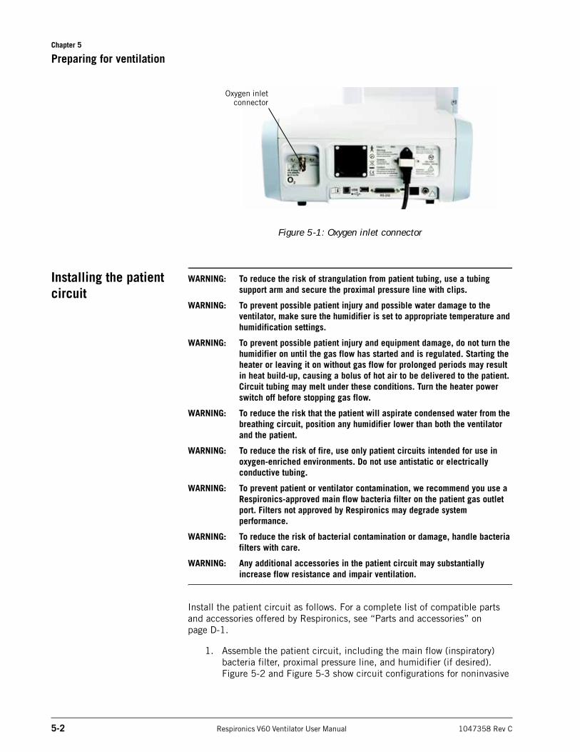
Connect the oxygen hose to the ventilator’s oxygen inlet connector (Figure 5-1) or to the oxygen manifold, if applicable.
Chapter 5
5-2 Respironics V60 Ventilator User Manual 1047358 Rev C
Preparing for ventilation
Figure 5-1: Oxygen inlet connector
Installing the patient circuit
WARNING: To reduce the risk of strangulation from patient tubing, use a tubing support arm and secure the proximal pressure line with clips.
WARNING: To prevent possible patient injury and possible water damage to the ventilator, make sure the humidifier is set to appropriate temperature and humidification settings.
WARNING: To prevent possible patient injury and equipment damage, do not turn the humidifier on until the gas flow has started and is regulated. Starting the heater or leaving it on without gas flow for prolonged periods may result in heat build-up, causing a bolus of hot air to be delivered to the patient. Circuit tubing may melt under these conditions. Turn the heater power switch off before stopping gas flow.
WARNING: To reduce the risk that the patient will aspirate condensed water from the breathing circuit, position any humidifier lower than both the ventilator and the patient.
WARNING: To reduce the risk of fire, use only patient circuits intended for use in oxygen-enriched environments. Do not use antistatic or electrically conductive tubing.
WARNING: To prevent patient or ventilator contamination, we recommend you use a Respironics-approved main flow bacteria filter on the patient gas outlet port. Filters not approved by Respironics may degrade system performance.
WARNING: To reduce the risk of bacterial contamination or damage, handle bacteria filters with care.
WARNING: Any additional accessories in the patient circuit may substantially increase flow resistance and impair ventilation.
Install the patient circuit as follows. For a complete list of compatible parts and accessories offered by Respironics, see “Parts and accessories” on page D-1.
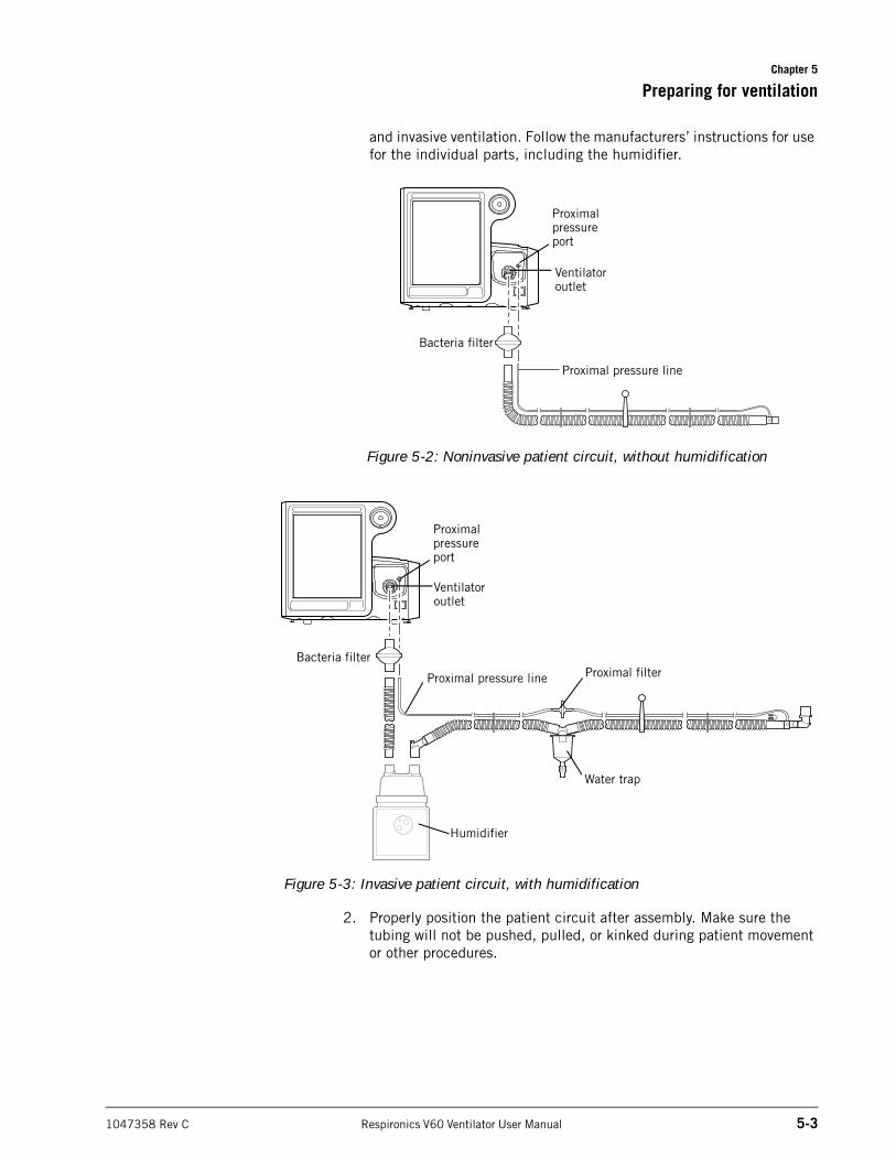
1. Assemble the patient circuit, including the main flow (inspiratory) bacteria filter, proximal pressure line, and humidifier (if desired). Figure 5-2 and Figure 5-3 show circuit configurations for noninvasive
Oxygen inletconnector
Chapter 5
Preparing for ventilation
1047358 Rev C Respironics V60 Ventilator User Manual 5-3
and invasive ventilation. Follow the manufacturers’ instructions for use for the individual parts, including the humidifier.
Figure 5-2: Noninvasive patient circuit, without humidification
Figure 5-3: Invasive patient circuit, with humidification
2. Properly position the patient circuit after assembly. Make sure the tubing will not be pushed, pulled, or kinked during patient movement or other procedures.
Proximal pressure line
Ventilator outlet
Bacteria filter
Proximal pressure port
Ventilator outlet
Proximal pressure line
Water trap
Humidifier
Proximal filterBacteria filter
Proximal pressure port
Chapter 5
5-4 Respironics V60 Ventilator User Manual 1047358 Rev C
Preparing for ventilation
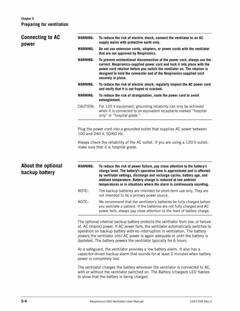
Connecting to AC power
WARNING: To reduce the risk of electric shock, connect the ventilator to an AC supply mains with protective earth only.
WARNING: Do not use extension cords, adapters, or power cords with the ventilator that are not approved by Respironics.
WARNING: To prevent unintentional disconnection of the power cord, always use the correct, Respironics-supplied power cord and lock it into place with the power cord retainer before you switch the ventilator on. The retainer is designed to hold the connector end of the Respironics-supplied cord securely in place.
WARNING: To reduce the risk of electric shock, regularly inspect the AC power cord and verify that it is not frayed or cracked.
WARNING: To reduce the risk of strangulation, route the power cord to avoid entanglement.
CAUTION: For 120 V equipment, grounding reliability can only be achieved when it is connected to an equivalent receptacle marked “hospital only” or “hospital grade.”
Plug the power cord into a grounded outlet that supplies AC power between 100 and 240 V, 50/60 Hz.
Always check the reliability of the AC outlet. If you are using a 120 V outlet, make sure that it is hospital grade.
About the optional backup battery
WARNING: To reduce the risk of power failure, pay close attention to the battery’s charge level. The battery’s operation time is approximate and is affected by ventilator settings, discharge and recharge cycles, battery age, and ambient temperature. Battery charge is reduced at low ambient temperatures or in situations where the alarm is continuously sounding.
NOTE: The backup batteries are intended for short-term use only. They are not intended to be a primary power source.
NOTE: We recommend that the ventilator’s batteries be fully charged before you ventilate a patient. If the batteries are not fully charged and AC power fails, always pay close attention to the level of battery charge.
The optional internal backup battery protects the ventilator from low, or failure of, AC (mains) power. If AC power fails, the ventilator automatically switches to operation on backup battery with no interruption in ventilation. The battery powers the ventilator until AC power is again adequate or until the battery is depleted. The battery powers the ventilator typically for 6 hours.
As a safeguard, the ventilator provides a low battery alarm. It also has a capacitor-driven backup alarm that sounds for at least 2 minutes when battery power is completely lost.
The ventilator charges the battery whenever the ventilator is connected to AC, with or without the ventilator switched on. The Battery (charged) LED flashes to show that the battery is being charged.
Chapter 5
Preparing for ventilation
1047358 Rev C Respironics V60 Ventilator User Manual 5-5
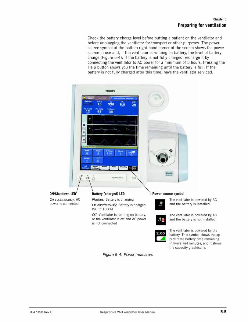
Check the battery charge level before putting a patient on the ventilator and before unplugging the ventilator for transport or other purposes. The power source symbol at the bottom right-hand corner of the screen shows the power source in use and, if the ventilator is running on battery, the level of battery charge (Figure 5-4). If the battery is not fully charged, recharge it by connecting the ventilator to AC power for a minimum of 5 hours. Pressing the Help button shows you the time remaining until the battery is full. If the battery is not fully charged after this time, have the ventilator serviced.
Figure 5-4: Power indicators
ON/Shutdown LED
On continuously: AC power is connected
Battery (charged) LED
Flashes: Battery is charging
On continuously: Battery is charged (90 to 100%)
Off: Ventilator is running on battery, or the ventilator is off and AC power is not connected
Power source symbol
The ventilator is powered by AC and the battery is installed.
The ventilator is powered by AC and the battery is not installed.
The ventilator is powered by the battery. This symbol shows the ap-proximate battery time remaining in hours and minutes, and it shows the capacity graphically.
Chapter 5
5-6 Respironics V60 Ventilator User Manual 1047358 Rev C
Preparing for ventilation
Starting up the ventilator
NOTE: Upon power-on the ventilator automatically runs a test of the backup audible alarm followed by the primary audible alarm. You should hear two high-pitched tones, followed by a beep approximately 2 seconds later. If you do not hear all of these sounds, discontinue use of the ventilator and have it serviced.
1. Power on the ventilator with the ON/Shutdown key.
2. Run the preoperational check on page 5-8.
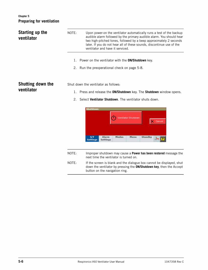
Shutting down the ventilator
Shut down the ventilator as follows:
1. Press and release the ON/Shutdown key. The Shutdown window opens.
2. Select Ventilator Shutdown. The ventilator shuts down.
NOTE: Improper shutdown may cause a Power has been restored message the next time the ventilator is turned on.
NOTE: If the screen is blank and the dialogue box cannot be displayed, shut down the ventilator by pressing the ON/Shutdown key, then the Accept button on the navigation ring.
Chapter 5
Preparing for ventilation
1047358 Rev C Respironics V60 Ventilator User Manual 5-7
Navigating the graphical user interface
Select a function by touching the desired tab or button on the touchscreen. Use this as the primary method to control the ventilator.
You can use the navigation ring as an alternative to the following touchscreen functions:
After making selections and adjusting values, accept selections by pressing the circular Accept button (the checkmark) in the middle of the navigation ring to accept and apply the change.
To open a window, touch the window tab.
To cancel a function and close the window, either select Cancel or touch another window tab.
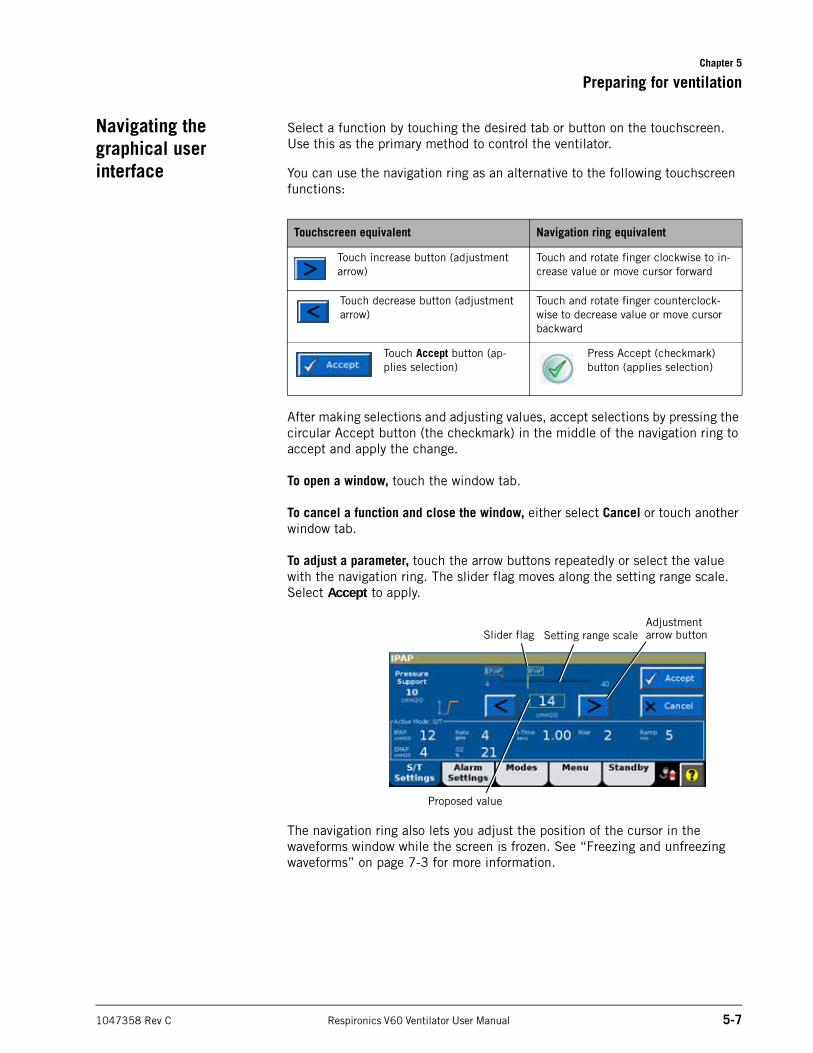
To adjust a parameter, touch the arrow buttons repeatedly or select the value with the navigation ring. The slider flag moves along the setting range scale. Select Accept to apply.
The navigation ring also lets you adjust the position of the cursor in the waveforms window while the screen is frozen. See “Freezing and unfreezing waveforms” on page 7-3 for more information.
Touchscreen equivalent Navigation ring equivalent
Touch increase button (adjustment arrow)
Touch and rotate finger clockwise to in-crease value or move cursor forward
Touch decrease button (adjustment arrow)
Touch and rotate finger counterclock-wise to decrease value or move cursor backward
Touch Accept button (ap-plies selection)
Press Accept (checkmark) button (applies selection)
Adjustment arrow buttonSlider flag Setting range scale
Proposed value
Chapter 5
5-8 Respironics V60 Ventilator User Manual 1047358 Rev C
Preparing for ventilation
Preoperational check WARNING: To ensure the ventilator’s safe operation, always run the full preoperational check described in “Preoperational check” on page 5-8 before using the ventilator on a patient. If the ventilator fails any tests, remove it from clinical use immediately. Do not use the ventilator until necessary repairs are completed and all tests have passed.
WARNING: To prevent possible patient injury, disconnect the patient from the ventilator before running the preoperational check. Make sure another source of ventilatory support is available.
Before you connect a new patient to the ventilator, run the preoperational check to verify the ventilator’s operation, including alarm functionality.
Required materialsTo ensure that the ventilator also functions according to specifications on your patient, we recommend that your test circuit be equivalent to the circuit used for ventilation.
• Breathing circuit, PN 582073 or the equivalent
• 1-L test lung, PN 1021671 or the equivalent
• CRITERION OxiCheck oxygen analyzer (PN 8-100661-00), Teledyne MX300 oxygen monitor, or the equivalent
Procedure
Do or observe... Verify...
1. Connect ventilator to AC power and the oxygen supply. Assemble the patient breathing circuit.
Breathing circuit is assembled correctly. See Figure 5-2 on page 5-3 or Figure 5-3 on page 5-3.
2. Switch on power. You hear tones from both the backup alarm (high pitch) and the primary alarm (lower pitch).
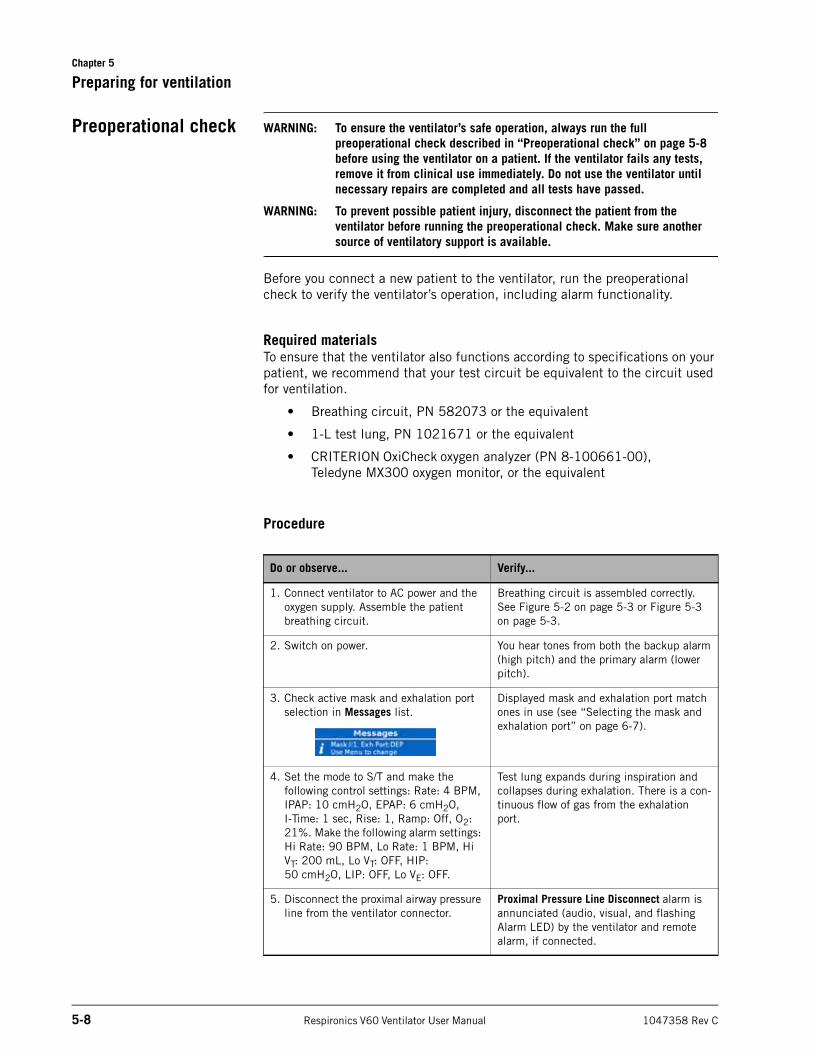
3. Check active mask and exhalation port selection in Messages list.
Displayed mask and exhalation port match ones in use (see “Selecting the mask and exhalation port” on page 6-7).
4. Set the mode to S/T and make the following control settings: Rate: 4 BPM, IPAP: 10 cmH2O, EPAP: 6 cmH2O,I-Time: 1 sec, Rise: 1, Ramp: Off, O2: 21%. Make the following alarm settings: Hi Rate: 90 BPM, Lo Rate: 1 BPM, Hi VT: 200 mL, Lo VT: OFF, HIP: 50 cmH2O, LIP: OFF, Lo VE: OFF.
Test lung expands during inspiration and collapses during exhalation. There is a con-tinuous flow of gas from the exhalation port.
5. Disconnect the proximal airway pressure line from the ventilator connector.
Proximal Pressure Line Disconnect alarm is annunciated (audio, visual, and flashing Alarm LED) by the ventilator and remote alarm, if connected.
Chapter 5
Preparing for ventilation
1047358 Rev C Respironics V60 Ventilator User Manual 5-9
TroubleshootingIf any test step fails, discontinue ventilator use and contact Respironics.
6. Reconnect the proximal airway pressure line, and manually reset alarm.
Proximal Pressure Line Disconnect alarm is reset.
7. Set O2 to 40%. Wait for oxygen concentration to stabilize.
Oxygen analyzer reads between 35 and 45%.
8. Disconnect the ventilator from AC power while the ventilator is running.
NOTE: If the ventilator has a backup battery, the battery must be adequately charged to run this test. Recharge as necessary before running the test.
If the optional backup battery is installed:
• The ventilator switches over to battery power (battery symbol in right-hand corner of screen is displayed).
• The green LED above the ON/Shutdown key remains lit.
• The audible alarm sounds intermittently.
• Running on Internal Battery is shown.
• The Battery LED is off.If the optional backup battery is not installed:
• An alternating backup alarm tone sounds and the Alarm LED flashes for a minimum of 2 minutes.
9. If the backup battery is installed, reconnect the ventilator to AC power.
• The alarm resets.
• The ventilator is again running on AC (symbol displayed in right-hand corner of screen).
• The Battery LED flashes to indicate the battery is charging.
10.Return settings to hospital-standard values.
WARNING:To prevent possible patient injury, always return alarm settings to hospital-standard values after the preoperational check.
Do or observe... Verify...
Chapter 5
5-10 Respironics V60 Ventilator User Manual 1047358 Rev C
Preparing for ventilation
Alarm tests The ventilator performs a self-check during start-up and continuously during operation. Alarm functionality is verified by this self-check. You may also want to run alarm tests, which demonstrate the alarms’ operation.
WARNING: To prevent possible patient injury, always return alarm settings to hospital-standard values after the preoperational check.
Preparation
1. Set the ventilator up as for normal ventilation, complete with breathing circuit (PN 582073 or the equivalent) and a 1-liter test lung assembly (PN 1021671).
2. Set the mode to S/T and make the following control settings: Rate: 4 BPM, IPAP: 10 cmH2O, EPAP: 6 cmH2O, I-Time: 1 sec, Rise: 1, Ramp: Off, O2: 21%.
3. Make the following alarm settings: Hi Rate: 90 BPM, Lo Rate: 1 BPM, Hi VT: 200 mL, Lo VT: OFF, HIP: 50 cmH2O, LIP: OFF, Lo E: OFF, LIP T: 5 secs.
High Inspiratory Pressure
1. Lower the HIP alarm limit to 8 cmH2O.
2. VERIFY that the High Inspiratory Pressure alarm is activated, the ventilator cycles into exhalation, and pressure falls to 6 cmH2O (the EPAP level).
3. Raise the HIP alarm limit to 15 cmH2O.
Low Tidal Volume
1. Raise the Lo VT alarm setting above the displayed, measured VT.
2. VERIFY that the Low Tidal Volume alarm is activated.
3. Turn the Lo VT alarm setting OFF.
4. VERIFY that the alarm resets.
V•
Chapter 5
Preparing for ventilation
1047358 Rev C Respironics V60 Ventilator User Manual 5-11
Patient Disconnect
1. Disconnect the test lung.
2. VERIFY that the Patient Disconnect alarm is activated.
3. Reconnect the test lung.
4. VERIFY that the alarm resets and that the ventilator automatically resumes ventilation.
Patient Circuit Occluded
1. Disconnect the patient circuit (including bacteria filter) from the ventilator outlet, and block the ventilator outlet with your thumb.
2. VERIFY that the Patient Circuit Occluded alarm is activated.
3. Unblock the outlet, and reconnect the circuit.
4. VERIFY that the alarm resets.
Chapter 5
5-12 Respironics V60 Ventilator User Manual 1047358 Rev C
Preparing for ventilation
(This page is intentionally blank.)
1047358 Rev C Respironics V60 Ventilator User Manual 6-1
Chapter 6. Operation
WARNING: To ensure the ventilator’s safe operation, always run the full preoperational check described in “Preoperational check” on page 5-8 before using the ventilator on a patient. If the ventilator fails any tests, remove it from clinical use immediately. Do not use the ventilator until necessary repairs are completed and all tests have passed.
NOTE: Before operation, prepare the ventilator as instructed in Chapter 5.
After power-on, the ventilator starts up in the mode and with the settings that were active before last power down. Check these settings and adjust as required. You must be familiar with using the touchscreen and navigation ring to select, adjust, activate, and confirm parameters. For details, see “Navigating the graphical user interface” on page 5-7.
Access the ventilator setting windows from the tabs at the bottom of the screen.
page 6-3 page 6-6 page 6-2 page 6-11 page 6-12 page 6-14
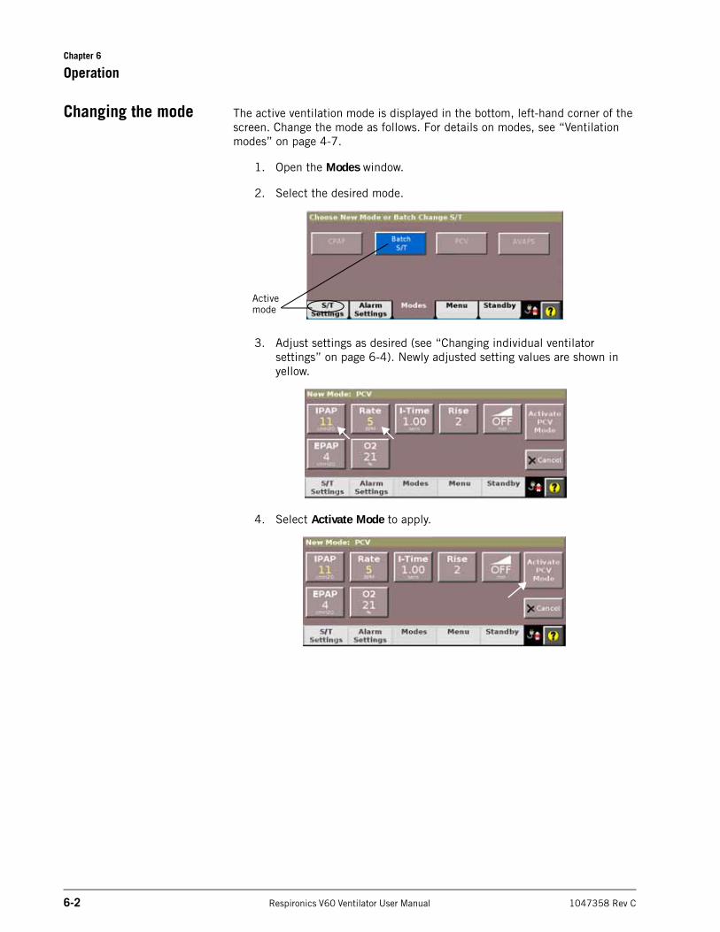
Chapter 6
6-2 Respironics V60 Ventilator User Manual 1047358 Rev C
Operation
Changing the mode The active ventilation mode is displayed in the bottom, left-hand corner of the screen. Change the mode as follows. For details on modes, see “Ventilation modes” on page 4-7.
1. Open the Modes window.
2. Select the desired mode.
3. Adjust settings as desired (see “Changing individual ventilator settings” on page 6-4). Newly adjusted setting values are shown in yellow.
4. Select Activate Mode to apply.
Active mode
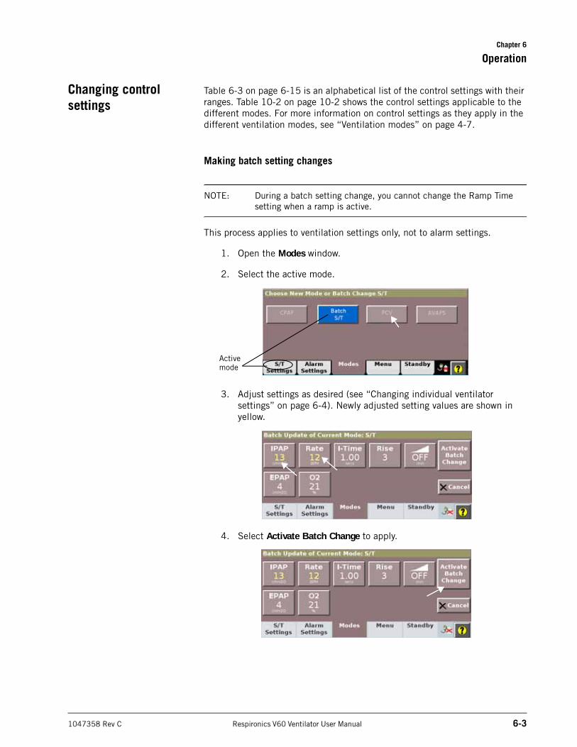
Chapter 6
Operation
1047358 Rev C Respironics V60 Ventilator User Manual 6-3
Changing control settings
Table 6-3 on page 6-15 is an alphabetical list of the control settings with their ranges. Table 10-2 on page 10-2 shows the control settings applicable to the different modes. For more information on control settings as they apply in the different ventilation modes, see “Ventilation modes” on page 4-7.
Making batch setting changes
NOTE: During a batch setting change, you cannot change the Ramp Time setting when a ramp is active.
This process applies to ventilation settings only, not to alarm settings.
1. Open the Modes window.
2. Select the active mode.
3. Adjust settings as desired (see “Changing individual ventilator settings” on page 6-4). Newly adjusted setting values are shown in yellow.
4. Select Activate Batch Change to apply.
Active mode
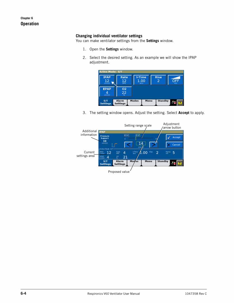
Chapter 6
6-4 Respironics V60 Ventilator User Manual 1047358 Rev C
Operation
Changing individual ventilator settingsYou can make ventilator settings from the Settings window.
1. Open the Settings window.
2. Select the desired setting. As an example we will show the IPAP adjustment.
3. The setting window opens. Adjust the setting. Select Accept to apply.
Adjustment arrow button
Currentsettings area
Setting range scale
Additionalinformation
Proposed value
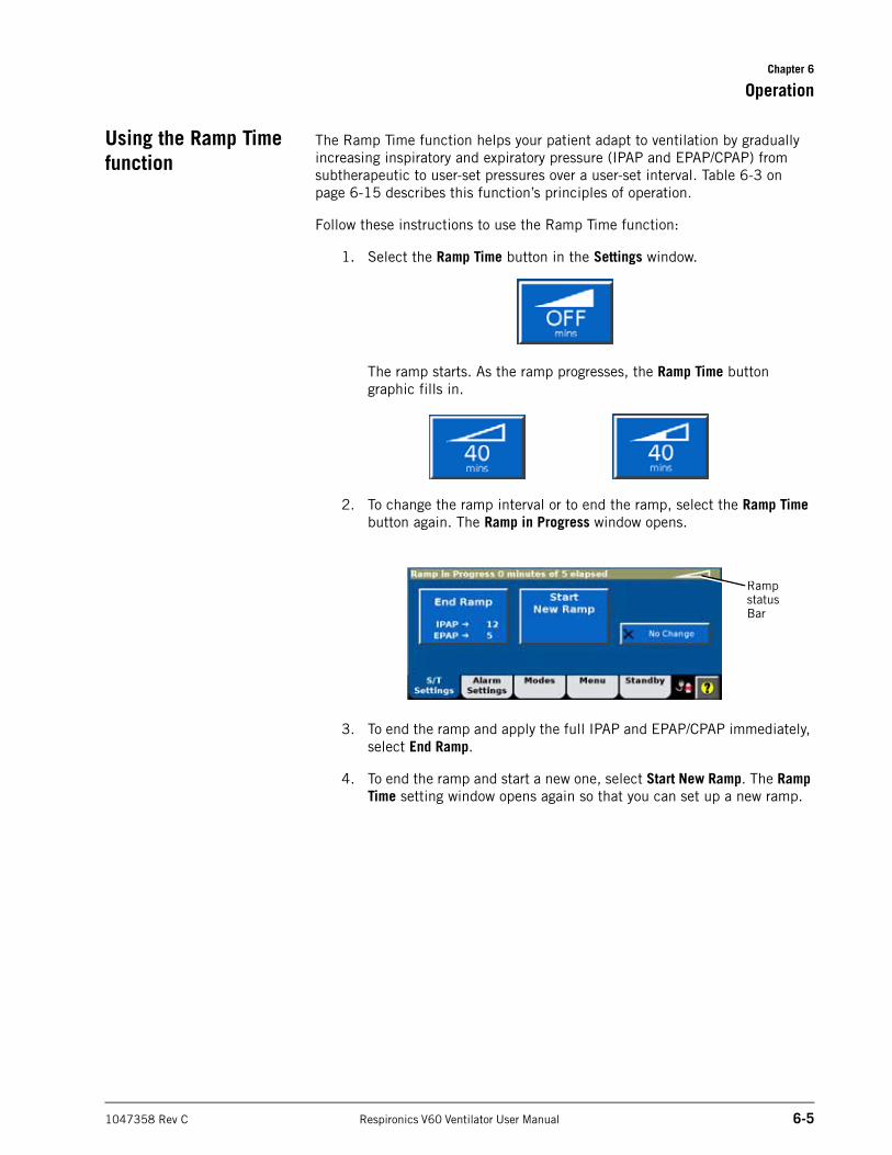
Chapter 6
Operation
1047358 Rev C Respironics V60 Ventilator User Manual 6-5
Using the Ramp Time function
The Ramp Time function helps your patient adapt to ventilation by gradually increasing inspiratory and expiratory pressure (IPAP and EPAP/CPAP) from subtherapeutic to user-set pressures over a user-set interval. Table 6-3 on page 6-15 describes this function’s principles of operation.
Follow these instructions to use the Ramp Time function:
1. Select the Ramp Time button in the Settings window.
The ramp starts. As the ramp progresses, the Ramp Time button graphic fills in.
2. To change the ramp interval or to end the ramp, select the Ramp Time button again. The Ramp in Progress window opens.
3. To end the ramp and apply the full IPAP and EPAP/CPAP immediately, select End Ramp.
4. To end the ramp and start a new one, select Start New Ramp. The Ramp Time setting window opens again so that you can set up a new ramp.
Ramp status Bar
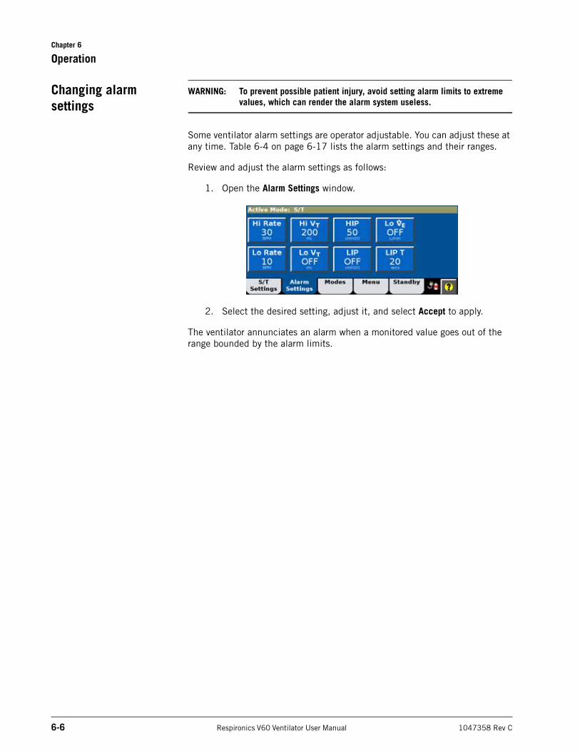
Chapter 6
6-6 Respironics V60 Ventilator User Manual 1047358 Rev C
Operation
Changing alarm settings
WARNING: To prevent possible patient injury, avoid setting alarm limits to extreme values, which can render the alarm system useless.
Some ventilator alarm settings are operator adjustable. You can adjust these at any time. Table 6-4 on page 6-17 lists the alarm settings and their ranges.
Review and adjust the alarm settings as follows:
1. Open the Alarm Settings window.
2. Select the desired setting, adjust it, and select Accept to apply.
The ventilator annunciates an alarm when a monitored value goes out of the range bounded by the alarm limits.
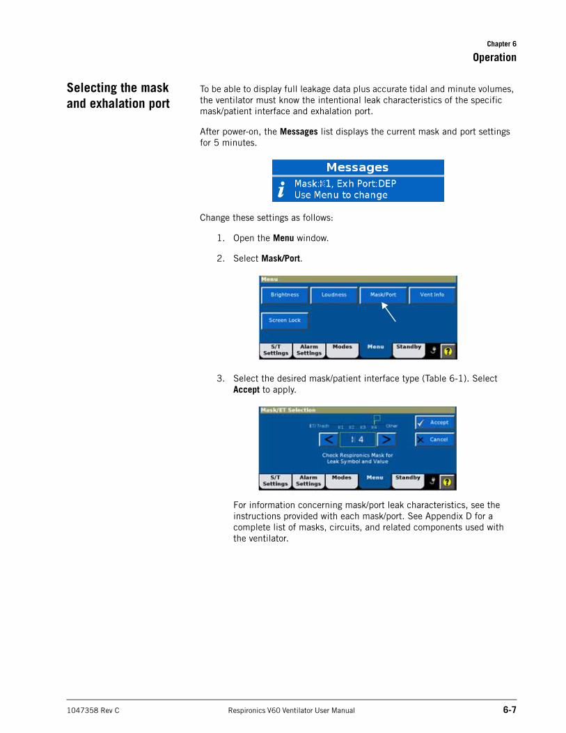
Chapter 6
Operation
1047358 Rev C Respironics V60 Ventilator User Manual 6-7
Selecting the mask and exhalation port
To be able to display full leakage data plus accurate tidal and minute volumes, the ventilator must know the intentional leak characteristics of the specific mask/patient interface and exhalation port.
After power-on, the Messages list displays the current mask and port settings for 5 minutes.
Change these settings as follows:
1. Open the Menu window.
2. Select Mask/Port.
3. Select the desired mask/patient interface type (Table 6-1). Select Accept to apply.
For information concerning mask/port leak characteristics, see the instructions provided with each mask/port. See Appendix D for a complete list of masks, circuits, and related components used with the ventilator.
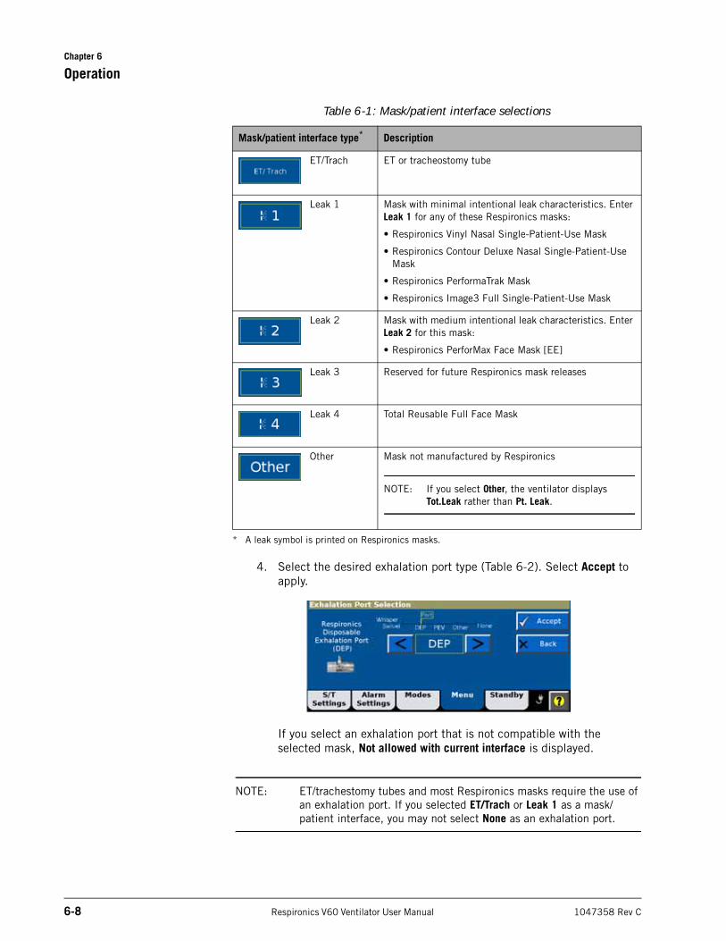
Chapter 6
6-8 Respironics V60 Ventilator User Manual 1047358 Rev C
Operation
4. Select the desired exhalation port type (Table 6-2). Select Accept to apply.
If you select an exhalation port that is not compatible with the selected mask, Not allowed with current interface is displayed.
NOTE: ET/trachestomy tubes and most Respironics masks require the use of an exhalation port. If you selected ET/Trach or Leak 1 as a mask/patient interface, you may not select None as an exhalation port.
Table 6-1: Mask/patient interface selections
Mask/patient interface type* Description
ET/Trach ET or tracheostomy tube
Leak 1 Mask with minimal intentional leak characteristics. Enter Leak 1 for any of these Respironics masks:
• Respironics Vinyl Nasal Single-Patient-Use Mask
• Respironics Contour Deluxe Nasal Single-Patient-Use Mask
• Respironics PerformaTrak Mask
• Respironics Image3 Full Single-Patient-Use Mask
Leak 2 Mask with medium intentional leak characteristics. Enter Leak 2 for this mask:
• Respironics PerforMax Face Mask [EE]
Leak 3 Reserved for future Respironics mask releases
Leak 4 Total Reusable Full Face Mask
Other Mask not manufactured by Respironics
NOTE: If you select Other, the ventilator displays Tot.Leak rather than Pt. Leak.
* A leak symbol is printed on Respironics masks.
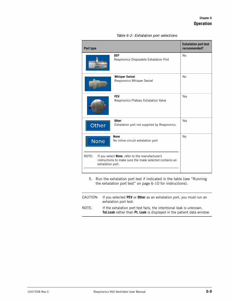
Chapter 6
Operation
1047358 Rev C Respironics V60 Ventilator User Manual 6-9
5. Run the exhalation port test if indicated in the table (see “Running the exhalation port test” on page 6-10 for instructions).
CAUTION: If you selected PEV or Other as an exhalation port, you must run an exhalation port test.
NOTE: If the exhalation port test fails, the intentional leak is unknown. Tot.Leak rather than Pt. Leak is displayed in the patient data window.
Table 6-2: Exhalation port selections
Port typeExhalation port test recommended?
DEPRespironics Disposable Exhalation Port
No
Whisper SwivelRespironics Whisper Swivel
No
PEVRespironics Plateau Exhalation Valve
Yes
OtherExhalation port not supplied by Respironics.
Yes
NoneNo inline circuit exhalation port
NOTE: If you select None, refer to the manufacturer’s instructions to make sure the mask selected contains an exhalation port.
No
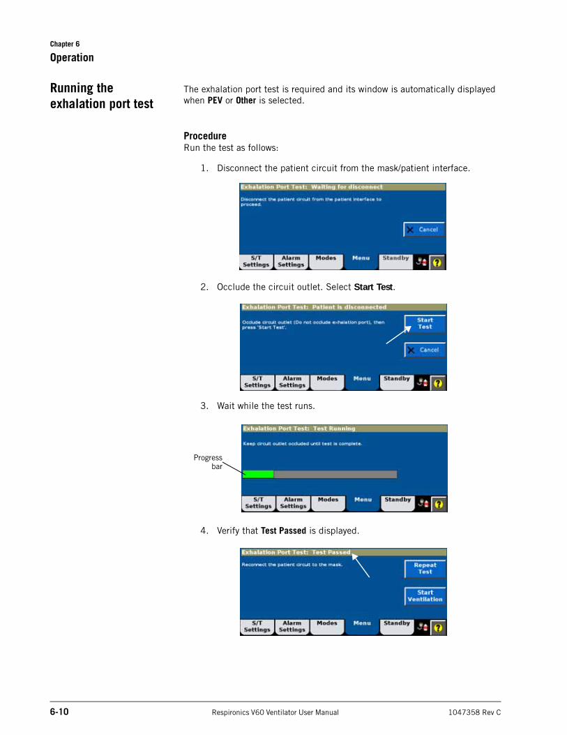
Chapter 6
6-10 Respironics V60 Ventilator User Manual 1047358 Rev C
Operation
Running the exhalation port test
The exhalation port test is required and its window is automatically displayed when PEV or Other is selected.
ProcedureRun the test as follows:
1. Disconnect the patient circuit from the mask/patient interface.
2. Occlude the circuit outlet. Select Start Test.
3. Wait while the test runs.
4. Verify that Test Passed is displayed.
Progressbar
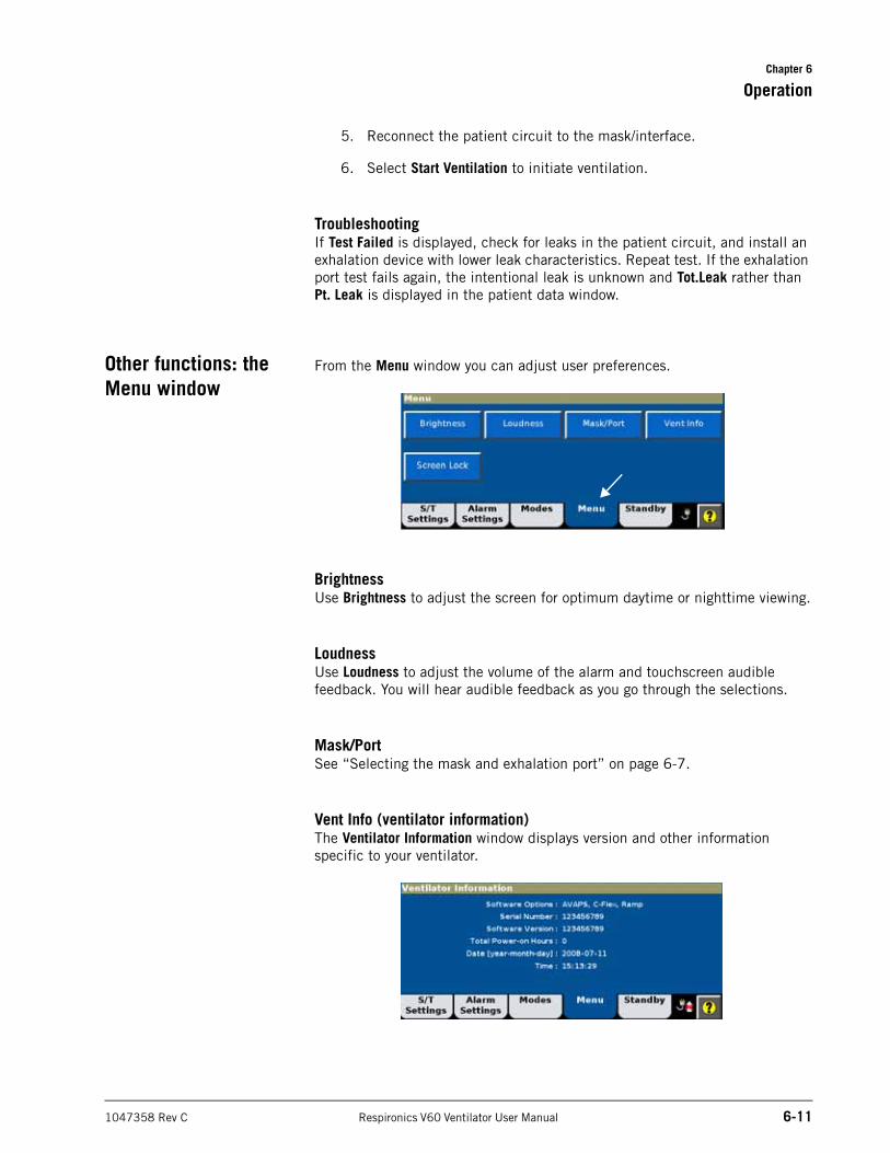
Chapter 6
Operation
1047358 Rev C Respironics V60 Ventilator User Manual 6-11
5. Reconnect the patient circuit to the mask/interface.
6. Select Start Ventilation to initiate ventilation.
TroubleshootingIf Test Failed is displayed, check for leaks in the patient circuit, and install an exhalation device with lower leak characteristics. Repeat test. If the exhalation port test fails again, the intentional leak is unknown and Tot.Leak rather than Pt. Leak is displayed in the patient data window.
Other functions: the Menu window
From the Menu window you can adjust user preferences.
BrightnessUse Brightness to adjust the screen for optimum daytime or nighttime viewing.
LoudnessUse Loudness to adjust the volume of the alarm and touchscreen audible feedback. You will hear audible feedback as you go through the selections.
Mask/PortSee “Selecting the mask and exhalation port” on page 6-7.
Vent Info (ventilator information)The Ventilator Information window displays version and other information specific to your ventilator.
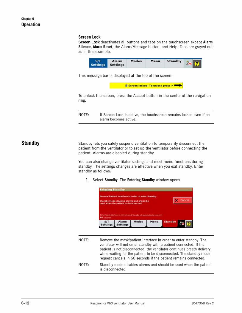
Chapter 6
6-12 Respironics V60 Ventilator User Manual 1047358 Rev C
Operation
Screen LockScreen Lock deactivates all buttons and tabs on the touchscreen except Alarm Silence, Alarm Reset, the Alarm/Message button, and Help. Tabs are grayed out as in this example.
This message bar is displayed at the top of the screen:
To unlock the screen, press the Accept button in the center of the navigation ring.
NOTE: If Screen Lock is active, the touchscreen remains locked even if an alarm becomes active.
Standby Standby lets you safely suspend ventilation to temporarily disconnect the patient from the ventilator or to set up the ventilator before connecting the patient. Alarms are disabled during standby.
You can also change ventilator settings and most menu functions during standby. The settings changes are effective when you exit standby. Enter standby as follows:
1. Select Standby. The Entering Standby window opens.
NOTE: Remove the mask/patient interface in order to enter standby. The ventilator will not enter standby with a patient connected. If the patient is not disconnected, the ventilator continues breath delivery while waiting for the patient to be disconnected. The standby mode request cancels in 60 seconds if the patient remains connected.
NOTE: Standby mode disables alarms and should be used when the patient is disconnected.
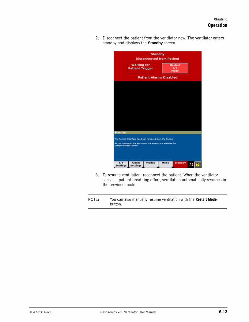
Chapter 6
Operation
1047358 Rev C Respironics V60 Ventilator User Manual 6-13
2. Disconnect the patient from the ventilator now. The ventilator enters standby and displays the Standby screen.
3. To resume ventilation, reconnect the patient. When the ventilator senses a patient breathing effort, ventilation automatically resumes in the previous mode.
NOTE: You can also manually resume ventilation with the Restart Mode button.
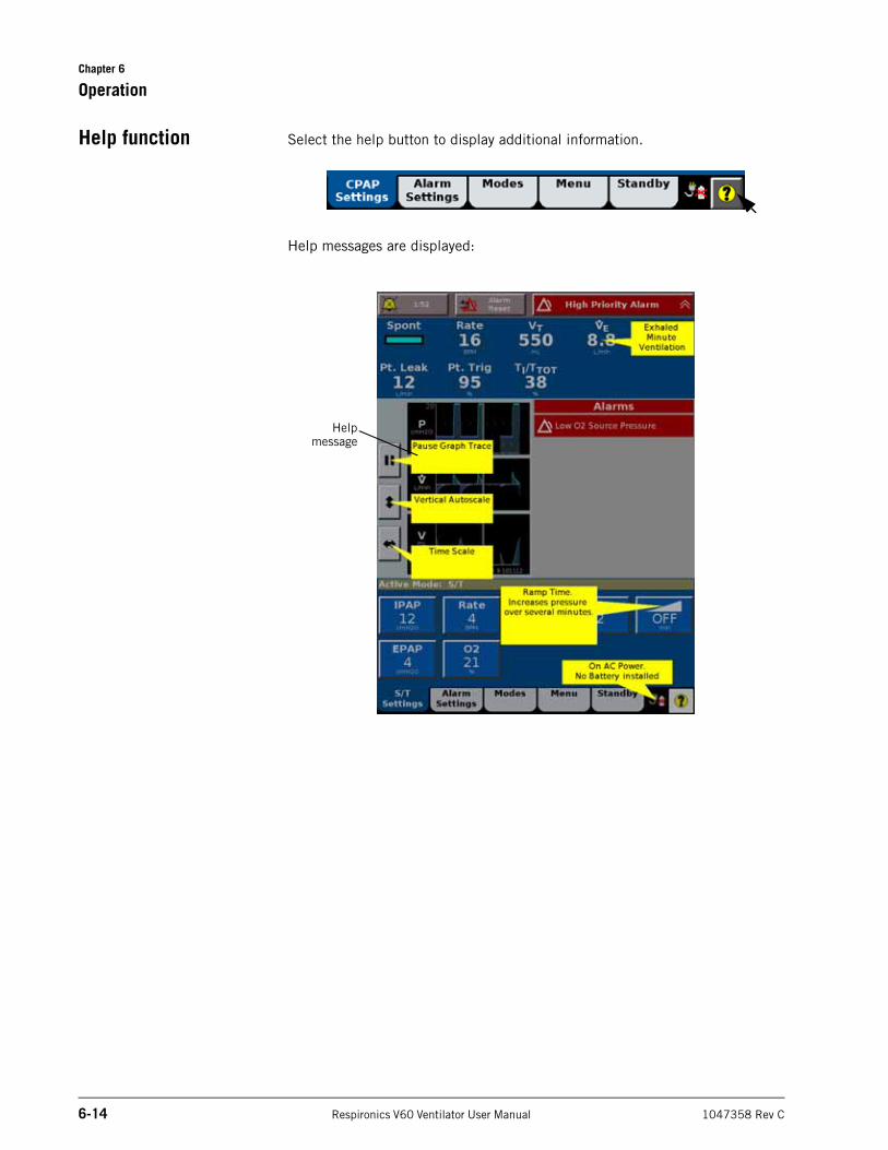
Chapter 6
6-14 Respironics V60 Ventilator User Manual 1047358 Rev C
Operation
Help function Select the help button to display additional information.
Help messages are displayed:
Helpmessage
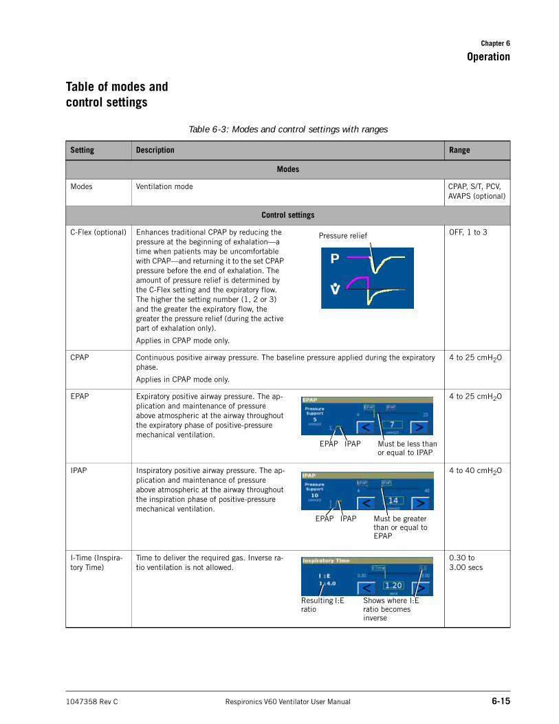
Chapter 6
Operation
1047358 Rev C Respironics V60 Ventilator User Manual 6-15
Table of modes and control settings
Table 6-3: Modes and control settings with ranges
Setting Description Range
Modes
Modes Ventilation mode CPAP, S/T, PCV, AVAPS (optional)
Control settings
C-Flex (optional) Enhances traditional CPAP by reducing the pressure at the beginning of exhalation––a time when patients may be uncomfortable with CPAP––and returning it to the set CPAP pressure before the end of exhalation. The amount of pressure relief is determined by the C-Flex setting and the expiratory flow. The higher the setting number (1, 2 or 3) and the greater the expiratory flow, the greater the pressure relief (during the active part of exhalation only).
Applies in CPAP mode only.
OFF, 1 to 3
CPAP Continuous positive airway pressure. The baseline pressure applied during the expiratory phase.
Applies in CPAP mode only.
4 to 25 cmH2O
EPAP Expiratory positive airway pressure. The ap-plication and maintenance of pressure above atmospheric at the airway throughout the expiratory phase of positive-pressure mechanical ventilation.
4 to 25 cmH2O
IPAP Inspiratory positive airway pressure. The ap-plication and maintenance of pressure above atmospheric at the airway throughout the inspiration phase of positive-pressure mechanical ventilation.
4 to 40 cmH2O
I-Time (Inspira-tory Time)
Time to deliver the required gas. Inverse ra-tio ventilation is not allowed.
0.30 to 3.00 secs
Pressure relief
Must be less than or equal to IPAP
EPAP IPAP
Must be greater than or equal to EPAP
EPAP IPAP
Shows where I:E ratio becomes inverse
Resulting I:E ratio
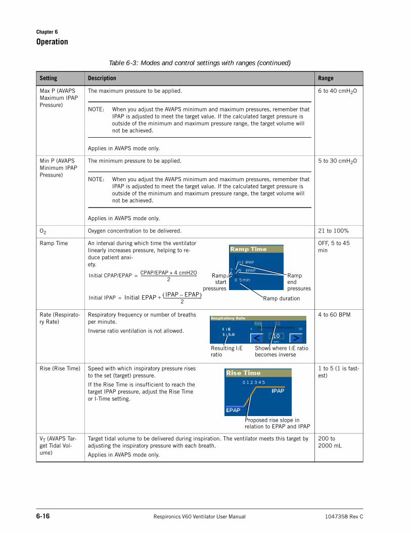
Chapter 6
6-16 Respironics V60 Ventilator User Manual 1047358 Rev C
Operation
Max P (AVAPS Maximum IPAP Pressure)
The maximum pressure to be applied.
NOTE: When you adjust the AVAPS minimum and maximum pressures, remember that IPAP is adjusted to meet the target value. If the calculated target pressure is outside of the minimum and maximum pressure range, the target volume will not be achieved.
Applies in AVAPS mode only.
6 to 40 cmH2O
Min P (AVAPS Minimum IPAP Pressure)
The minimum pressure to be applied.
NOTE: When you adjust the AVAPS minimum and maximum pressures, remember that IPAP is adjusted to meet the target value. If the calculated target pressure is outside of the minimum and maximum pressure range, the target volume will not be achieved.
Applies in AVAPS mode only.
5 to 30 cmH2O
O2 Oxygen concentration to be delivered. 21 to 100%
Ramp Time An interval during which time the ventilator linearly increases pressure, helping to re-duce patient anxi-ety.
OFF, 5 to 45 min
Rate (Respirato-ry Rate)
Respiratory frequency or number of breaths per minute.
Inverse ratio ventilation is not allowed.
4 to 60 BPM
Rise (Rise Time) Speed with which inspiratory pressure rises to the set (target) pressure.
If the Rise Time is insufficient to reach the target IPAP pressure, adjust the Rise Time or I-Time setting.
1 to 5 (1 is fast-est)
VT (AVAPS Tar-get Tidal Vol-ume)
Target tidal volume to be delivered during inspiration. The ventilator meets this target by adjusting the inspiratory pressure with each breath.
Applies in AVAPS mode only.
200 to 2000 mL
Table 6-3: Modes and control settings with ranges (continued)
Setting Description Range
Initial CPAP/EPAP CPAP/EPAP 4 cmH2O+2
---------------------------------------------------------------=
Initial IPAP Initial EPAP IPAP EPAP– 2
-------------------------------------------+= Ramp duration
Rampstart
pressures
Ramp end pressures
Shows where I:E ratio becomes inverse
Resulting I:E ratio
Proposed rise slope in relation to EPAP and IPAP
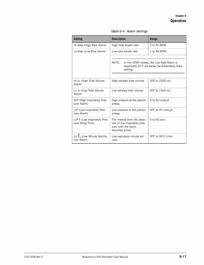
Chapter 6
Operation
1047358 Rev C Respironics V60 Ventilator User Manual 6-17
Table 6-4: Alarm settings
Setting Description Range
Hi Rate (High Rate Alarm) High total breath rate. 5 to 90 BPM
Lo Rate (Low Rate Alarm) Low total breath rate. 1 to 89 BPM
NOTE: In non-CPAP modes, the Low Rate Alarm is essentially off if set below the Respiratory Rate setting.
Hi VT (High Tidal Volume Alarm)
High exhaled tidal volume. 200 to 2500 mL
Lo VT (Low Tidal Volume Alarm)
Low exhaled tidal volume. OFF to 1500 mL
HIP (High Inspiratory Pres-sure Alarm)
High pressure at the patient airway.
5 to 50 cmH2O
LIP (Low Inspiratory Pres-sure Alarm)
Low pressure at the patient airway.
OFF to 40 cmH2O
LIP T (Low Inspiratory Pres-sure Delay Time)
The interval from the detec-tion of low inspiratory pres-sure until the alarm becomes active.
5 to 60 secs
Lo E (Low Minute Ventila-tion Alarm)
Low expiratory minute vol-ume.
OFF to 99.0 L/minV•
Chapter 6
6-18 Respironics V60 Ventilator User Manual 1047358 Rev C
Operation
(This page is intentionally blank.)
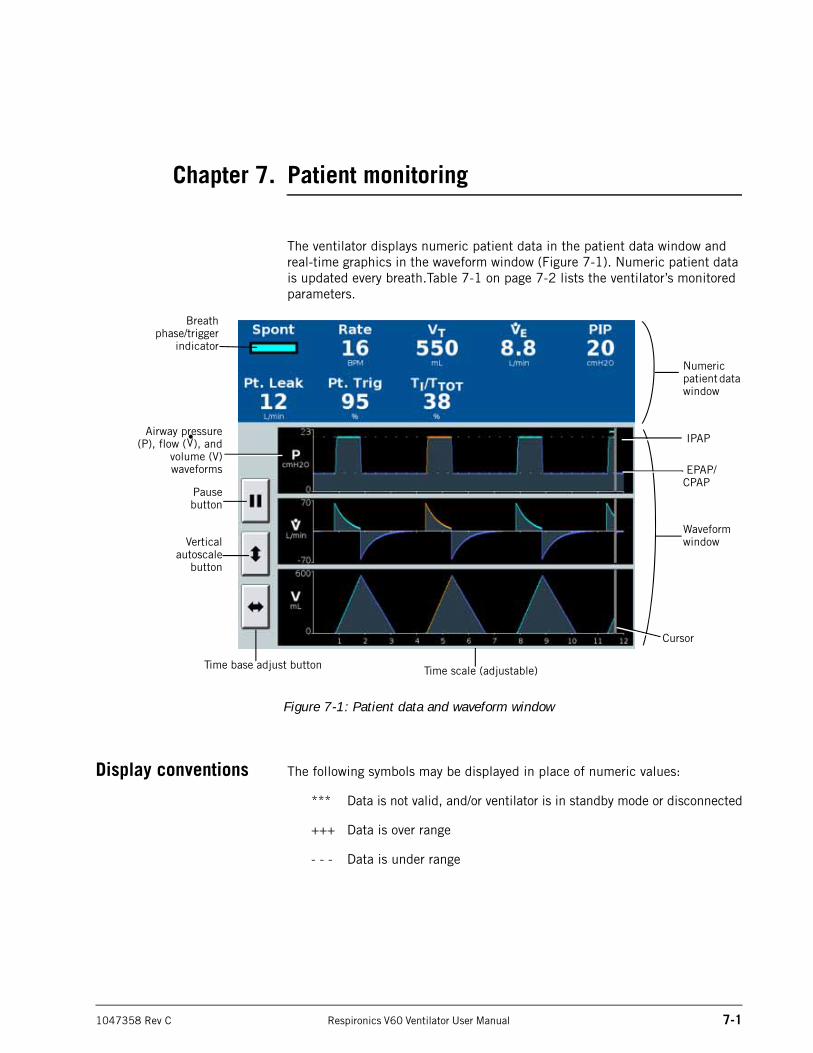
1047358 Rev C Respironics V60 Ventilator User Manual 7-1
Chapter 7. Patient monitoring
The ventilator displays numeric patient data in the patient data window and real-time graphics in the waveform window (Figure 7-1). Numeric patient data is updated every breath.Table 7-1 on page 7-2 lists the ventilator’s monitored parameters.
Figure 7-1: Patient data and waveform window
Display conventions The following symbols may be displayed in place of numeric values:
*** Data is not valid, and/or ventilator is in standby mode or disconnected
+++ Data is over range
- - - Data is under range
Numeric patient data window
Verticalautoscale
button
Pausebutton
Time base adjust button
Waveform window
Cursor
Time scale (adjustable)
Breathphase/trigger
indicator
Airway pressure(P), flow ( ), and
volume (V)waveforms
V• IPAP
EPAP/CPAP
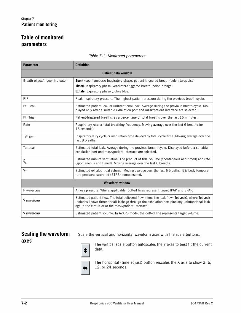
Chapter 7
7-2 Respironics V60 Ventilator User Manual 1047358 Rev C
Patient monitoring
Table of monitored parameters
Scaling the waveform axes
Scale the vertical and horizontal waveform axes with the scale buttons.
The vertical scale button autoscales the Y axes to best fit the current data.
The horizontal (time adjust) button rescales the X axis to show 3, 6, 12, or 24 seconds.
Table 7-1: Monitored parameters
Parameter Definition
Patient data window
Breath phase/trigger indicator Spont (spontaneous): Inspiratory phase, patient-triggered breath (color: turquoise)
Timed: Inspiratory phase, ventilator-triggered breath (color: orange)
Exhale: Expiratory phase (color: blue)
PIP Peak inspiratory pressure. The highest patient pressure during the previous breath cycle.
Pt. Leak Estimated patient leak or unintentional leak. Average during the previous breath cycle. Dis-played only after a suitable exhalation port and mask/patient interface are selected.
Pt. Trig Patient-triggered breaths, as a percentage of total breaths over the last 15 minutes.
Rate Respiratory rate or total breathing frequency. Moving average over the last 6 breaths (or 15 seconds).
TI/TTOT Inspiratory duty cycle or inspiration time divided by total cycle time. Moving average over the last 8 breaths.
Tot.Leak Estimated total leak. Average during the previous breath cycle. Displayed before a suitable exhalation port and mask/patient interface are selected.
VEEstimated minute ventilation. The product of tidal volume (spontaneous and timed) and rate (spontaneous and timed). Moving average over the last 6 breaths.
VT Estimated exhaled tidal volume. Moving average over the last 6 breaths. It is body tempera-ture pressure saturated (BTPS) compensated.
Waveform window
P waveform Airway pressure. Where applicable, dotted lines represent target IPAP and EPAP.
V waveformEstimated patient flow. The total delivered flow minus the leak flow (Tot.Leak), where Tot.Leak includes known (intentional) leakage through the exhalation port plus any unintentional leak-age in the circuit or at the mask/patient interface.
V waveform Estimated patient volume. In AVAPS mode, the dotted line represents target volume.
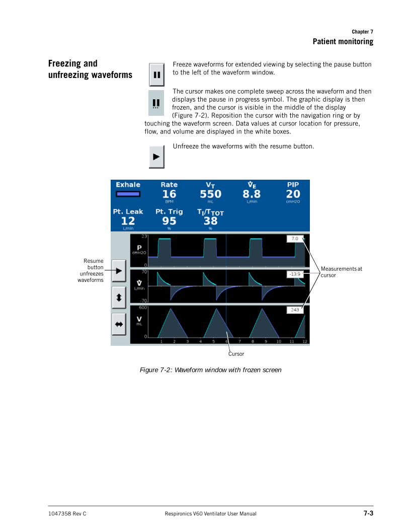
Chapter 7
Patient monitoring
1047358 Rev C Respironics V60 Ventilator User Manual 7-3
Freezing and unfreezing waveforms
Freeze waveforms for extended viewing by selecting the pause button to the left of the waveform window.
The cursor makes one complete sweep across the waveform and then displays the pause in progress symbol. The graphic display is then frozen, and the cursor is visible in the middle of the display (Figure 7-2). Reposition the cursor with the navigation ring or by
touching the waveform screen. Data values at cursor location for pressure, flow, and volume are displayed in the white boxes.
Unfreeze the waveforms with the resume button.
Figure 7-2: Waveform window with frozen screen
Resumebutton
unfreezeswaveforms
Cursor
Measurements at cursor
Chapter 7
7-4 Respironics V60 Ventilator User Manual 1047358 Rev C
Patient monitoring
(This page is intentionally blank.)
1047358 Rev C Respironics V60 Ventilator User Manual 8-1
Chapter 8. Alarms and messages
Alarms and messages on the ventilator alert you to situations that require your attention. The ventilator can also actuate remote alarms. Figure 8-1 on page 2 shows the visual alarm characteristics. Table 8-2 on page 8-6 summarizes the different types of alarm and tells you how to respond to each.
Responding to alarms WARNING: If AC power fails and the backup battery is not installed or is depleted, an audible and visual alarm annunciates for at least 2 minutes. Immediately discontinue ventilator use and secure an alternative means of ventilation. As in most ventilators with passive exhalation ports, when power is lost, sufficient air is not provided through the circuit and exhaled air may be rebreathed.
NOTE: If an alarm persists for no apparent reason, discontinue ventilator use and contact Respironics.
Respond to an alarm as follows:
1. Approach the patient immediately. Secure sufficient and effective ventilation for the patient. You may silence the alarm if possible.
2. Correct the alarm condition, referring to the alarm messages in Table 8-2.
You can modify alarm settings at any time through the Alarm Settings tab.
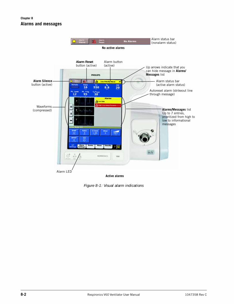
Chapter 8
8-2 Respironics V60 Ventilator User Manual 1047358 Rev C
Alarms and messages
Figure 8-1: Visual alarm indications
Alarm Silencebutton (active)
Waveforms(compressed)
Alarm Reset button (active)
Alarm button (active)
Autoreset alarm (strikeout line through message)
Alarms/Messages listUp to 7 entries, prioritized from high to low to informational messages
Alarm status bar (active alarm status)
Up arrows indicate that you can hide message in Alarms/Messages list
Alarm LED
Alarm status bar (nonalarm status)
No active alarms
Active alarms
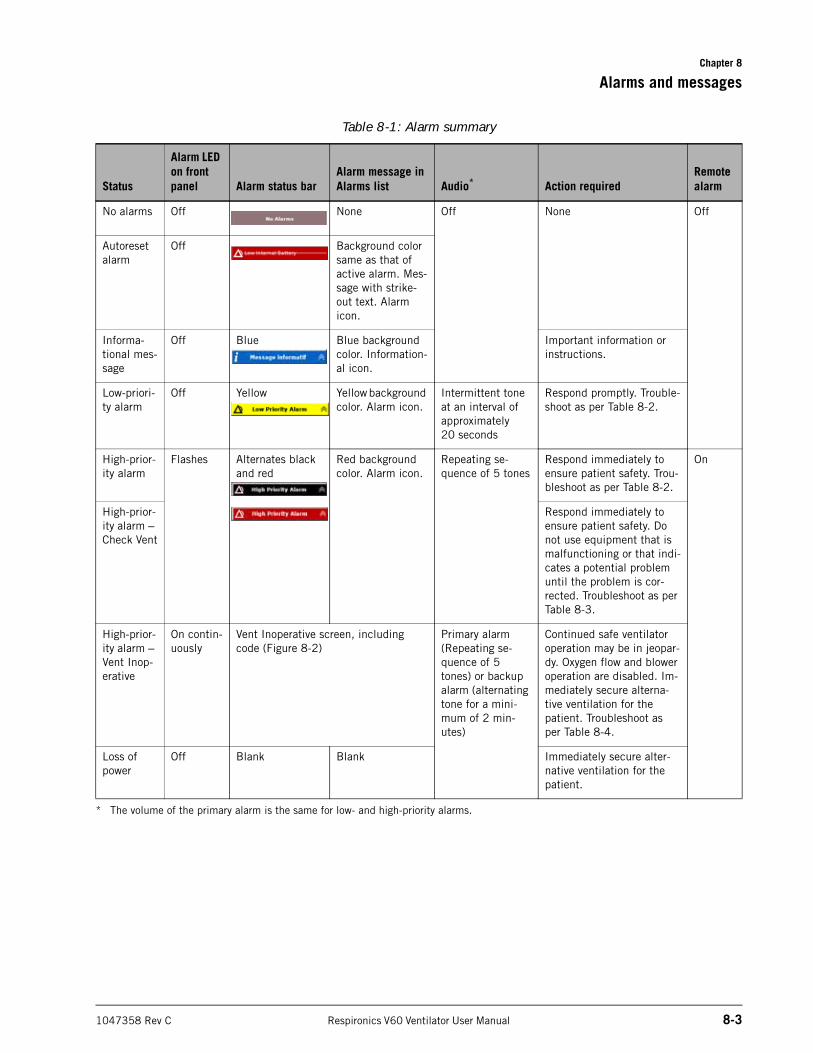
Chapter 8
Alarms and messages
1047358 Rev C Respironics V60 Ventilator User Manual 8-3
Table 8-1: Alarm summary
Status
Alarm LED on front panel Alarm status bar
Alarm message in Alarms list Audio*
* The volume of the primary alarm is the same for low- and high-priority alarms.
Action requiredRemote alarm
No alarms Off None Off None Off
Autoreset alarm
Off Background color same as that of active alarm. Mes-sage with strike-out text. Alarm icon.
Informa-tional mes-sage
Off Blue Blue background color. Information-al icon.
Important information or instructions.
Low-priori-ty alarm
Off Yellow Yellow background color. Alarm icon.
Intermittent tone at an interval of approximately 20 seconds
Respond promptly. Trouble-shoot as per Table 8-2.
High-prior-ity alarm
Flashes Alternates black and red
Red background color. Alarm icon.
Repeating se-quence of 5 tones
Respond immediately to ensure patient safety. Trou-bleshoot as per Table 8-2.
On
High-prior-ity alarm – Check Vent
Respond immediately to ensure patient safety. Do not use equipment that is malfunctioning or that indi-cates a potential problem until the problem is cor-rected. Troubleshoot as per Table 8-3.
High-prior-ity alarm – Vent Inop-erative
On contin-uously
Vent Inoperative screen, including code (Figure 8-2)
Primary alarm (Repeating se-quence of 5 tones) or backup alarm (alternating tone for a mini-mum of 2 min-utes)
Continued safe ventilator operation may be in jeopar-dy. Oxygen flow and blower operation are disabled. Im-mediately secure alterna-tive ventilation for the patient. Troubleshoot as per Table 8-4.
Loss of power
Off Blank Blank Immediately secure alter-native ventilation for the patient.
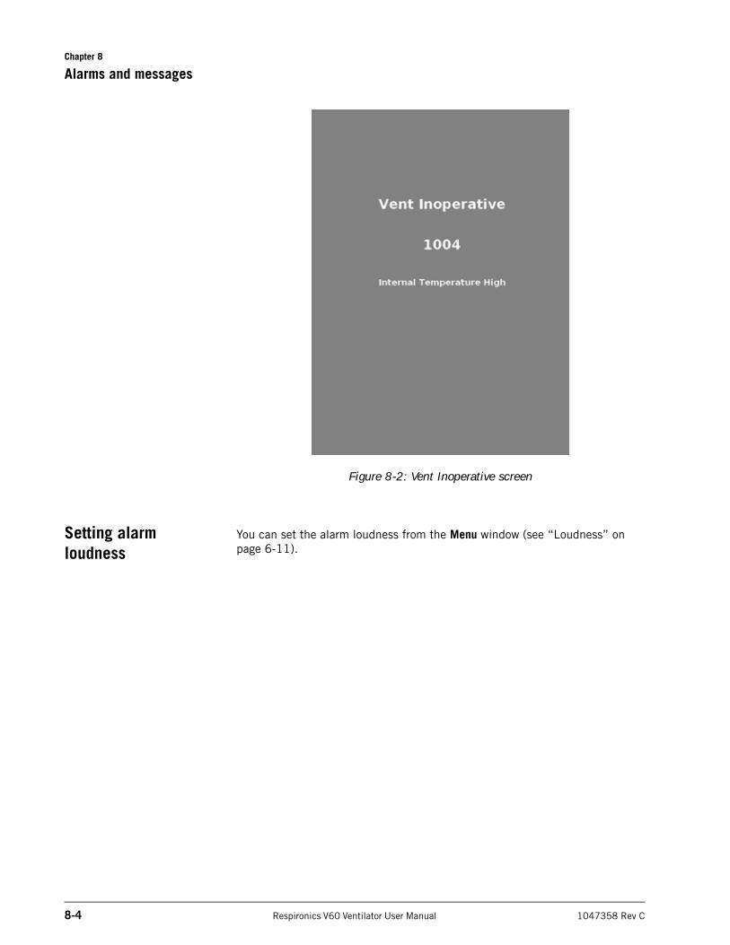
Chapter 8
8-4 Respironics V60 Ventilator User Manual 1047358 Rev C
Alarms and messages
Figure 8-2: Vent Inoperative screen
Setting alarm loudness
You can set the alarm loudness from the Menu window (see “Loudness” on page 6-11).
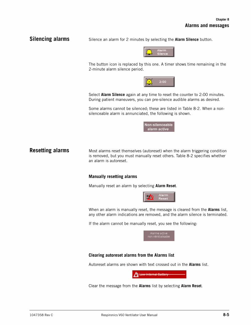
Chapter 8
Alarms and messages
1047358 Rev C Respironics V60 Ventilator User Manual 8-5
Silencing alarms Silence an alarm for 2 minutes by selecting the Alarm Silence button.
The button icon is replaced by this one. A timer shows time remaining in the 2-minute alarm silence period.
Select Alarm Silence again at any time to reset the counter to 2:00 minutes. During patient maneuvers, you can pre-silence audible alarms as desired.
Some alarms cannot be silenced; these are listed in Table 8-2. When a non-silenceable alarm is annunciated, the following is shown.
Resetting alarms Most alarms reset themselves (autoreset) when the alarm triggering condition is removed, but you must manually reset others. Table 8-2 specifies whether an alarm is autoreset.
Manually resetting alarms
Manually reset an alarm by selecting Alarm Reset.
When an alarm is manually reset, the message is cleared from the Alarms list, any other alarm indications are removed, and the alarm silence is terminated.
If the alarm cannot be manually reset, you see the following:
Clearing autoreset alarms from the Alarms list
Autoreset alarms are shown with text crossed out in the Alarms list.
Clear the message from the Alarms list by selecting Alarm Reset.
Chapter 8
8-6 Respironics V60 Ventilator User Manual 1047358 Rev C
Alarms and messages
Hiding/displaying alarm messages
To hide an alarm or informational message in the Alarms or Messages list, touch the flashing alarm indicator button or informational message button when up arrows are present. To display messages, touch the flashing alarm indicator or Informational Message button when down arrows are present. Both active and autoreset alarms and informational messages are displayed and hidden.
Alarms and other messages
Table 8-2 is a list of alarms and other messages displayed by the ventilator, along with descriptions, suggested corrective actions, and other information. The ID (identifier) listed with the priority type is the priority number of the alarm. This priority number determines the order of alarm message display. Unless otherwise indicated, alarms listed as autoresettable are reset when the alarm condition is removed.
Up arrows
Table 8-2: Alarm and other messages: summary and troubleshooting
Message Description Corrective ActionPriority type (ID)
Manually resettable
Autore-settable
Silence-able
AVAPS: Target VT Ex-ceeded. Min Pres-sure Too High
AVAPS target pressure is less than Min P setting. The ventilator limits its applied pressure to Min P.
Check the patient. Confirm pressure settings are com-patible with target. Evaluate pressure and volume set-tings.
Infor-mation (54)
No Yes N/A
AVAPS: Target VT Not Achieved. Insuffi-cient Max Pressure
AVAPS target pressure ex-ceeds Max P setting. The ventilator limits applied pressure to Max P.
Check the patient. Confirm pressure settings are com-patible with target. Evaluate pressure and volume set-tings.
Infor-mation (53)
No Yes N/A
Check Vent:description of failure
See Table 8-3 on page 8-10
High Inspiratory Pres-sure
Measured inspiratory pres-sure is greater than the HIP setting, and the ventilator cycles into exhalation. Au-toresets after a complete in-spiration without the alarm condition.
Check the patient. Confirm ventilator and alarm settings are appropriate. If problem persists, provide alternative ventilation. Have ventilator serviced.
High (39)
Yes Yes Yes
High O2 Supply Pres-sure
O2 inlet pressure is greater than 92 psig, so O2 enrich-ment ends. Autoresets when O2 supply pressure falls below 87 psig.
Check the patient. If prob-lem persists, provide alter-native ventilation. Have ventilator serviced.
High (44)
No Yes Yes
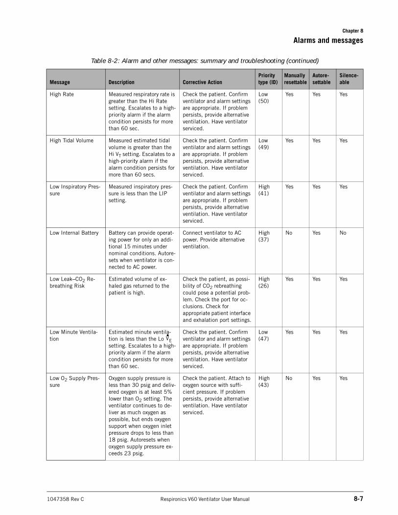
Chapter 8
Alarms and messages
1047358 Rev C Respironics V60 Ventilator User Manual 8-7
High Rate Measured respiratory rate is greater than the Hi Rate setting. Escalates to a high-priority alarm if the alarm condition persists for more than 60 sec.
Check the patient. Confirm ventilator and alarm settings are appropriate. If problem persists, provide alternative ventilation. Have ventilator serviced.
Low (50)
Yes Yes Yes
High Tidal Volume Measured estimated tidal volume is greater than the Hi VT setting. Escalates to a high-priority alarm if the alarm condition persists for more than 60 secs.
Check the patient. Confirm ventilator and alarm settings are appropriate. If problem persists, provide alternative ventilation. Have ventilator serviced.
Low (49)
Yes Yes Yes
Low Inspiratory Pres-sure
Measured inspiratory pres-sure is less than the LIP setting.
Check the patient. Confirm ventilator and alarm settings are appropriate. If problem persists, provide alternative ventilation. Have ventilator serviced.
High (41)
Yes Yes Yes
Low Internal Battery Battery can provide operat-ing power for only an addi-tional 15 minutes under nominal conditions. Autore-sets when ventilator is con-nected to AC power.
Connect ventilator to AC power. Provide alternative ventilation.
High (37)
No Yes No
Low Leak–CO2 Re-breathing Risk
Estimated volume of ex-haled gas returned to the patient is high.
Check the patient, as possi-bility of CO2 rebreathing could pose a potential prob-lem. Check the port for oc-clusions. Check for appropriate patient interface and exhalation port settings.
High (26)
Yes Yes Yes
Low Minute Ventila-tion
Estimated minute ventila-tion is less than the Lo E setting. Escalates to a high-priority alarm if the alarm condition persists for more than 60 sec.
Check the patient. Confirm ventilator and alarm settings are appropriate. If problem persists, provide alternative ventilation. Have ventilator serviced.
Low (47)
Yes Yes Yes
Low O2 Supply Pres-sure
Oxygen supply pressure is less than 30 psig and deliv-ered oxygen is at least 5% lower than O2 setting. The ventilator continues to de-liver as much oxygen as possible, but ends oxygen support when oxygen inlet pressure drops to less than 18 psig. Autoresets when oxygen supply pressure ex-ceeds 23 psig.
Check the patient. Attach to oxygen source with suffi-cient pressure. If problem persists, provide alternative ventilation. Have ventilator serviced.
High (43)
No Yes Yes
Table 8-2: Alarm and other messages: summary and troubleshooting (continued)
Message Description Corrective ActionPriority type (ID)
Manually resettable
Autore-settable
Silence-able
V•
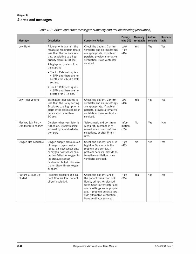
Chapter 8
8-8 Respironics V60 Ventilator User Manual 1047358 Rev C
Alarms and messages
Low Rate A low-priority alarm if the measured respiratory rate is less than the Lo Rate set-ting, escalating to a high-priority alarm in 60 sec.
A high-priority alarm from the start if:
• The Lo Rate setting is 4 BPM and there are no breaths for > 60/Lo Rate setting.
• The Lo Rate setting is > 4 BPM and there are no breaths for > 15 sec.
Check the patient. Confirm ventilator and alarm settings are appropriate. If problem persists, provide alternative ventilation. Have ventilator serviced.
Low/High (46)
Yes Yes Yes
Low Tidal Volume Estimated tidal volume is less than the Lo VT setting. Escalates to a high-priority alarm if the alarm condition persists for more than 60 sec.
Check the patient. Confirm ventilator and alarm settings are appropriate. If problem persists, provide alternative ventilation. Have ventilator serviced.
Low (48)
Yes Yes Yes
Mask:x, Exh Port:y Use Menu to change
Displays when ventilator is turned on. Displays select-ed mask type and exhala-tion port.
Select mask and port from Menu tab. Message is re-moved when user confirms selections, or after 5 min-utes.
Infor-mation (55)
No Yes N/A
Oxygen Not Available Oxygen supply pressure out of range, oxygen device failed, air flow sensor and/or oxygen flow sensor cali-bration failed, or oxygen in-let pressure sensor calibration failed. The ven-tilator discontinues oxygen support.
Check the patient. Check if high/low O2 source is the problem and correct. If problem persists, provide al-ternative ventilation. Have ventilator serviced.
High (42)
No Yes Yes
Patient Circuit Oc-cluded
Proximal pressure and pa-tient flow are low. Patient circuit occluded.
Check the patient. Check the patient circuit for bulk liquid, crimps, or blocked filter. Confirm ventilator and alarm settings are appropri-ate. If problem persists, pro-vide alternative ventilation. Have ventilator serviced.
High (35)
Yes Yes Yes
Table 8-2: Alarm and other messages: summary and troubleshooting (continued)
Message Description Corrective ActionPriority type (ID)
Manually resettable
Autore-settable
Silence-able
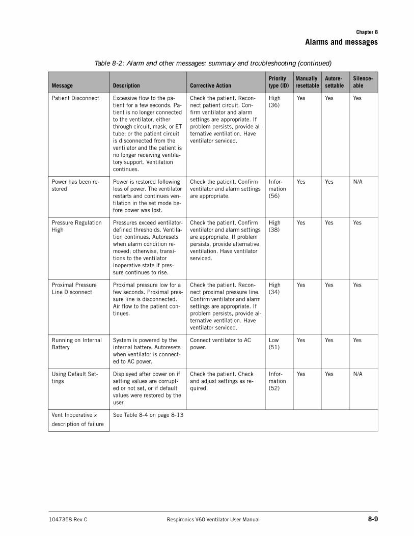
Chapter 8
Alarms and messages
1047358 Rev C Respironics V60 Ventilator User Manual 8-9
Patient Disconnect Excessive flow to the pa-tient for a few seconds. Pa-tient is no longer connected to the ventilator, either through circuit, mask, or ET tube; or the patient circuit is disconnected from the ventilator and the patient is no longer receiving ventila-tory support. Ventilation continues.
Check the patient. Recon-nect patient circuit. Con-firm ventilator and alarm settings are appropriate. If problem persists, provide al-ternative ventilation. Have ventilator serviced.
High (36)
Yes Yes Yes
Power has been re-stored
Power is restored following loss of power. The ventilator restarts and continues ven-tilation in the set mode be-fore power was lost.
Check the patient. Confirm ventilator and alarm settings are appropriate.
Infor-mation (56)
Yes Yes N/A
Pressure Regulation High
Pressures exceed ventilator-defined thresholds. Ventila-tion continues. Autoresets when alarm condition re-moved; otherwise, transi-tions to the ventilator inoperative state if pres-sure continues to rise.
Check the patient. Confirm ventilator and alarm settings are appropriate. If problem persists, provide alternative ventilation. Have ventilator serviced.
High (38)
Yes Yes Yes
Proximal Pressure Line Disconnect
Proximal pressure low for a few seconds. Proximal pres-sure line is disconnected. Air flow to the patient con-tinues.
Check the patient. Recon-nect proximal pressure line. Confirm ventilator and alarm settings are appropriate. If problem persists, provide al-ternative ventilation. Have ventilator serviced.
High (34)
Yes Yes Yes
Running on Internal Battery
System is powered by the internal battery. Autoresets when ventilator is connect-ed to AC power.
Connect ventilator to AC power.
Low (51)
Yes Yes Yes
Using Default Set-tings
Displayed after power on if setting values are corrupt-ed or not set, or if default values were restored by the user.
Check the patient. Check and adjust settings as re-quired.
Infor-mation (52)
Yes Yes N/A
Vent Inoperative x
description of failure
See Table 8-4 on page 8-13
Table 8-2: Alarm and other messages: summary and troubleshooting (continued)
Message Description Corrective ActionPriority type (ID)
Manually resettable
Autore-settable
Silence-able
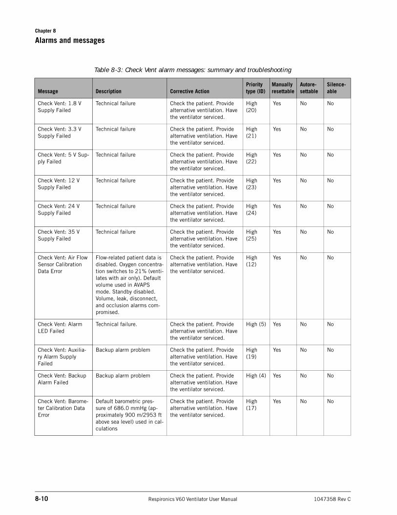
Chapter 8
8-10 Respironics V60 Ventilator User Manual 1047358 Rev C
Alarms and messages
Table 8-3: Check Vent alarm messages: summary and troubleshooting
Message Description Corrective ActionPriority type (ID)
Manually resettable
Autore-settable
Silence-able
Check Vent: 1.8 V Supply Failed
Technical failure Check the patient. Provide alternative ventilation. Have the ventilator serviced.
High (20)
Yes No No
Check Vent: 3.3 V Supply Failed
Technical failure Check the patient. Provide alternative ventilation. Have the ventilator serviced.
High (21)
Yes No No
Check Vent: 5 V Sup-ply Failed
Technical failure Check the patient. Provide alternative ventilation. Have the ventilator serviced.
High (22)
Yes No No
Check Vent: 12 V Supply Failed
Technical failure Check the patient. Provide alternative ventilation. Have the ventilator serviced.
High (23)
Yes No No
Check Vent: 24 V Supply Failed
Technical failure Check the patient. Provide alternative ventilation. Have the ventilator serviced.
High (24)
Yes No No
Check Vent: 35 V Supply Failed
Technical failure Check the patient. Provide alternative ventilation. Have the ventilator serviced.
High (25)
Yes No No
Check Vent: Air Flow Sensor Calibration Data Error
Flow-related patient data is disabled. Oxygen concentra-tion switches to 21% (venti-lates with air only). Default volume used in AVAPS mode. Standby disabled. Volume, leak, disconnect, and occlusion alarms com-promised.
Check the patient. Provide alternative ventilation. Have the ventilator serviced.
High (12)
Yes No No
Check Vent: Alarm LED Failed
Technical failure. Check the patient. Provide alternative ventilation. Have the ventilator serviced.
High (5) Yes No No
Check Vent: Auxilia-ry Alarm Supply Failed
Backup alarm problem Check the patient. Provide alternative ventilation. Have the ventilator serviced.
High (19)
Yes No No
Check Vent: Backup Alarm Failed
Backup alarm problem Check the patient. Provide alternative ventilation. Have the ventilator serviced.
High (4) Yes No No
Check Vent: Barome-ter Calibration Data Error
Default barometric pres-sure of 686.0 mmHg (ap-proximately 900 m/2953 ft above sea level) used in cal-culations
Check the patient. Provide alternative ventilation. Have the ventilator serviced.
High (17)
Yes No No
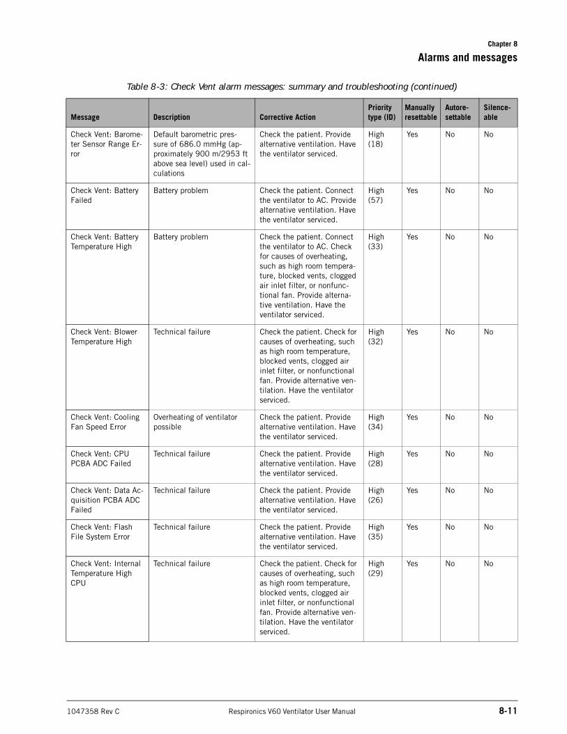
Chapter 8
Alarms and messages
1047358 Rev C Respironics V60 Ventilator User Manual 8-11
Check Vent: Barome-ter Sensor Range Er-ror
Default barometric pres-sure of 686.0 mmHg (ap-proximately 900 m/2953 ft above sea level) used in cal-culations
Check the patient. Provide alternative ventilation. Have the ventilator serviced.
High (18)
Yes No No
Check Vent: Battery Failed
Battery problem Check the patient. Connect the ventilator to AC. Provide alternative ventilation. Have the ventilator serviced.
High (57)
Yes No No
Check Vent: Battery Temperature High
Battery problem Check the patient. Connect the ventilator to AC. Check for causes of overheating, such as high room tempera-ture, blocked vents, clogged air inlet filter, or nonfunc-tional fan. Provide alterna-tive ventilation. Have the ventilator serviced.
High (33)
Yes No No
Check Vent: Blower Temperature High
Technical failure Check the patient. Check for causes of overheating, such as high room temperature, blocked vents, clogged air inlet filter, or nonfunctional fan. Provide alternative ven-tilation. Have the ventilator serviced.
High (32)
Yes No No
Check Vent: Cooling Fan Speed Error
Overheating of ventilator possible
Check the patient. Provide alternative ventilation. Have the ventilator serviced.
High (34)
Yes No No
Check Vent: CPU PCBA ADC Failed
Technical failure Check the patient. Provide alternative ventilation. Have the ventilator serviced.
High (28)
Yes No No
Check Vent: Data Ac-quisition PCBA ADC Failed
Technical failure Check the patient. Provide alternative ventilation. Have the ventilator serviced.
High (26)
Yes No No
Check Vent: Flash File System Error
Technical failure Check the patient. Provide alternative ventilation. Have the ventilator serviced.
High (35)
Yes No No
Check Vent: Internal Temperature High CPU
Technical failure Check the patient. Check for causes of overheating, such as high room temperature, blocked vents, clogged air inlet filter, or nonfunctional fan. Provide alternative ven-tilation. Have the ventilator serviced.
High (29)
Yes No No
Table 8-3: Check Vent alarm messages: summary and troubleshooting (continued)
Message Description Corrective ActionPriority type (ID)
Manually resettable
Autore-settable
Silence-able
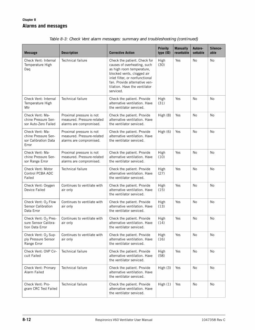
Chapter 8
8-12 Respironics V60 Ventilator User Manual 1047358 Rev C
Alarms and messages
Check Vent: Internal Temperature High Daq
Technical failure Check the patient. Check for causes of overheating, such as high room temperature, blocked vents, clogged air inlet filter, or nonfunctional fan. Provide alternative ven-tilation. Have the ventilator serviced.
High (30)
Yes No No
Check Vent: Internal Temperature High Mtr
Technical failure Check the patient. Provide alternative ventilation. Have the ventilator serviced.
High (31)
Yes No No
Check Vent: Ma-chine Pressure Sen-sor Auto-Zero Failed
Proximal pressure is not measured. Pressure-related alarms are compromised.
Check the patient. Provide alternative ventilation. Have the ventilator serviced.
High (8) Yes No No
Check Vent: Ma-chine Pressure Sen-sor Calibration Data Error
Proximal pressure is not measured. Pressure-related alarms are compromised.
Check the patient. Provide alternative ventilation. Have the ventilator serviced.
High (6) Yes No No
Check Vent: Ma-chine Pressure Sen-sor Range Error
Proximal pressure is not measured. Pressure-related alarms are compromised.
Check the patient. Provide alternative ventilation. Have the ventilator serviced.
High (10)
Yes No No
Check Vent: Motor Control PCBA ADC Failed
Technical failure Check the patient. Provide alternative ventilation. Have the ventilator serviced.
High (27)
Yes No No
Check Vent: Oxygen Device Failed
Continues to ventilate with air only
Check the patient. Provide alternative ventilation. Have the ventilator serviced.
High (15)
Yes No No
Check Vent: O2 Flow Sensor Calibration Data Error
Continues to ventilate with air only
Check the patient. Provide alternative ventilation. Have the ventilator serviced.
High (13)
Yes No No
Check Vent: O2 Pres-sure Sensor Calibra-tion Data Error
Continues to ventilate with air only
Check the patient. Provide alternative ventilation. Have the ventilator serviced.
High (14)
Yes No No
Check Vent: O2 Sup-ply Pressure Sensor Range Error
Continues to ventilate with air only
Check the patient. Provide alternative ventilation. Have the ventilator serviced.
High (16)
Yes No No
Check Vent: OVP Cir-cuit Failed
Technical failure Check the patient. Provide alternative ventilation. Have the ventilator serviced.
High (58)
Yes No No
Check Vent: Primary Alarm Failed
Technical failure Check the patient. Provide alternative ventilation. Have the ventilator serviced.
High (3) Yes No No
Check Vent: Pro-gram CRC Test Failed
Technical failure Check the patient. Provide alternative ventilation. Have the ventilator serviced.
High (1) Yes No No
Table 8-3: Check Vent alarm messages: summary and troubleshooting (continued)
Message Description Corrective ActionPriority type (ID)
Manually resettable
Autore-settable
Silence-able
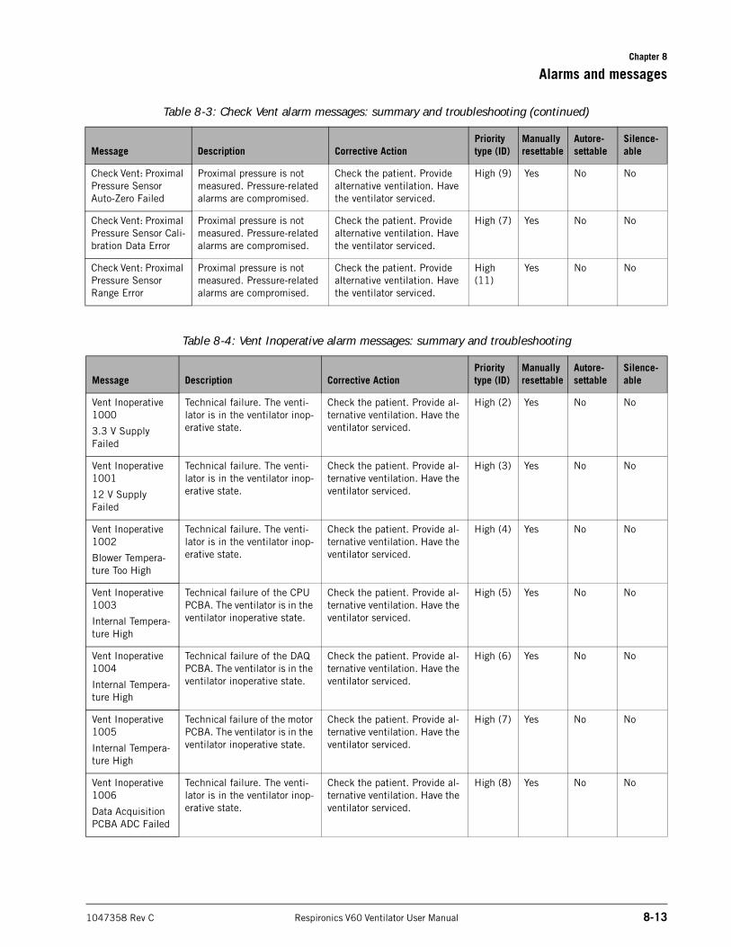
Chapter 8
Alarms and messages
1047358 Rev C Respironics V60 Ventilator User Manual 8-13
Check Vent: Proximal Pressure Sensor Auto-Zero Failed
Proximal pressure is not measured. Pressure-related alarms are compromised.
Check the patient. Provide alternative ventilation. Have the ventilator serviced.
High (9) Yes No No
Check Vent: Proximal Pressure Sensor Cali-bration Data Error
Proximal pressure is not measured. Pressure-related alarms are compromised.
Check the patient. Provide alternative ventilation. Have the ventilator serviced.
High (7) Yes No No
Check Vent: Proximal Pressure Sensor Range Error
Proximal pressure is not measured. Pressure-related alarms are compromised.
Check the patient. Provide alternative ventilation. Have the ventilator serviced.
High (11)
Yes No No
Table 8-4: Vent Inoperative alarm messages: summary and troubleshooting
Message Description Corrective ActionPriority type (ID)
Manually resettable
Autore-settable
Silence-able
Vent Inoperative 1000
3.3 V Supply Failed
Technical failure. The venti-lator is in the ventilator inop-erative state.
Check the patient. Provide al-ternative ventilation. Have the ventilator serviced.
High (2) Yes No No
Vent Inoperative 1001
12 V Supply Failed
Technical failure. The venti-lator is in the ventilator inop-erative state.
Check the patient. Provide al-ternative ventilation. Have the ventilator serviced.
High (3) Yes No No
Vent Inoperative 1002
Blower Tempera-ture Too High
Technical failure. The venti-lator is in the ventilator inop-erative state.
Check the patient. Provide al-ternative ventilation. Have the ventilator serviced.
High (4) Yes No No
Vent Inoperative 1003
Internal Tempera-ture High
Technical failure of the CPU PCBA. The ventilator is in the ventilator inoperative state.
Check the patient. Provide al-ternative ventilation. Have the ventilator serviced.
High (5) Yes No No
Vent Inoperative 1004
Internal Tempera-ture High
Technical failure of the DAQ PCBA. The ventilator is in the ventilator inoperative state.
Check the patient. Provide al-ternative ventilation. Have the ventilator serviced.
High (6) Yes No No
Vent Inoperative 1005
Internal Tempera-ture High
Technical failure of the motor PCBA. The ventilator is in the ventilator inoperative state.
Check the patient. Provide al-ternative ventilation. Have the ventilator serviced.
High (7) Yes No No
Vent Inoperative 1006
Data Acquisition PCBA ADC Failed
Technical failure. The venti-lator is in the ventilator inop-erative state.
Check the patient. Provide al-ternative ventilation. Have the ventilator serviced.
High (8) Yes No No
Table 8-3: Check Vent alarm messages: summary and troubleshooting (continued)
Message Description Corrective ActionPriority type (ID)
Manually resettable
Autore-settable
Silence-able
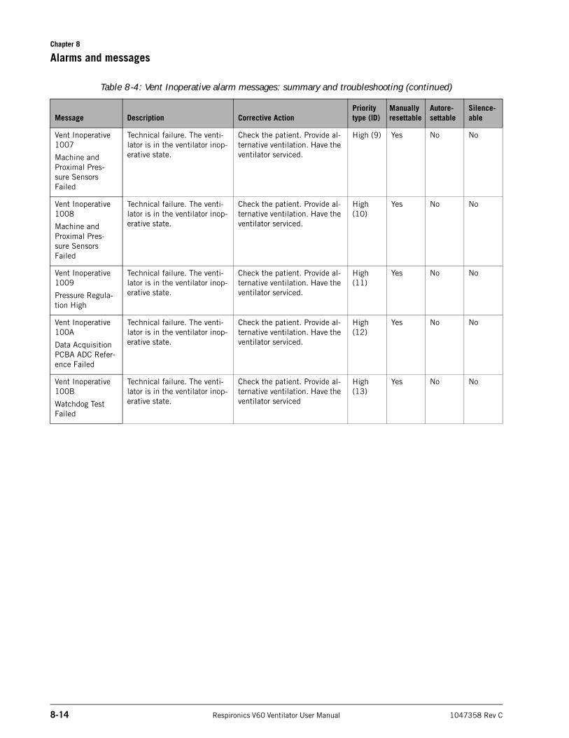
Chapter 8
8-14 Respironics V60 Ventilator User Manual 1047358 Rev C
Alarms and messages
Vent Inoperative 1007
Machine and Proximal Pres-sure Sensors Failed
Technical failure. The venti-lator is in the ventilator inop-erative state.
Check the patient. Provide al-ternative ventilation. Have the ventilator serviced.
High (9) Yes No No
Vent Inoperative 1008
Machine and Proximal Pres-sure Sensors Failed
Technical failure. The venti-lator is in the ventilator inop-erative state.
Check the patient. Provide al-ternative ventilation. Have the ventilator serviced.
High (10)
Yes No No
Vent Inoperative 1009
Pressure Regula-tion High
Technical failure. The venti-lator is in the ventilator inop-erative state.
Check the patient. Provide al-ternative ventilation. Have the ventilator serviced.
High (11)
Yes No No
Vent Inoperative 100A
Data Acquisition PCBA ADC Refer-ence Failed
Technical failure. The venti-lator is in the ventilator inop-erative state.
Check the patient. Provide al-ternative ventilation. Have the ventilator serviced.
High (12)
Yes No No
Vent Inoperative 100B
Watchdog Test Failed
Technical failure. The venti-lator is in the ventilator inop-erative state.
Check the patient. Provide al-ternative ventilation. Have the ventilator serviced
High (13)
Yes No No
Table 8-4: Vent Inoperative alarm messages: summary and troubleshooting (continued)
Message Description Corrective ActionPriority type (ID)
Manually resettable
Autore-settable
Silence-able
1047358 Rev C Respironics V60 Ventilator User Manual 9-1
Chapter 9. Care and maintenance
WARNING: To reduce the risk of electric shock, power down the ventilator and disconnect it from AC power before cleaning or servicing it.
WARNING: This product consists of devices that may contain mercury, which must be recycled or disposed of in accordance with local, state, or federal laws. (Within this system, the backlight lamps in the monitor display contain mercury.)
NOTE: It is the user’s responsibility to comply with the information provided in this chapter.
To ensure the safety and reliability of your ventilator, follow these maintenance procedures along with your own institutional policies for cleaning, disinfecting, and maintaining equipment. All the procedures in this manual are intended to be performed by the operator. For further maintenance, contact your service representative.
Decontamination CAUTION: To prevent possible damage to the ventilator, use only those cleaning agents listed in this manual.
CAUTION: Do not attempt to sterilize or autoclave the ventilator.
Ventilator exteriorUse a soft, moist, lint-free cloth to clean the outside surfaces of the ventilator. We recommend the following cleaning agents:
• Water
• Hydrogen peroxide (3%)
• Soapy water or mild detergent
• 10% bleach solution (10% bleach, 90% water)
• 91% isopropyl alcohol
• Germicidal disposable cloth (alkyl dimethyl benzyl ammonium chloride 0.07%; alkyl dimethyl ethybenzyl ammonium chloride 0.07%, remaining inert ingredients)
• Ammonium cleaner disinfectant
• Ethyl alcohol (70%)
Chapter 9
9-2 Respironics V60 Ventilator User Manual 1047358 Rev C
Care and maintenance
Touchscreen
CAUTION: To prevent possible damage to the touchscreen, take care when cleaning it. Do not drip water and/or soap solution. After cleaning and rinsing, remove all moisture with a dry, soft cloth. Never clean the touchscreen with an abrasive brush or device, since this will cause irreparable damage.
Dampen a soft cloth with isopropyl alcohol or a nonabrasive glass cleaner and wipe the screen. Avoid using cleaners other than glass cleaners. Do not use any vinegar-based solutions. Avoid using gritty cloths. Handle the touchscreen with care. To facilitate cleaning the touchscreen during ventilation, use the Screen Lock function.
Bacteria filter, patient circuit, and other accessoriesFollow the manufacturer’s guidelines.
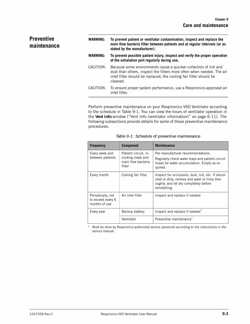
Chapter 9
Care and maintenance
1047358 Rev C Respironics V60 Ventilator User Manual 9-3
Preventive maintenance
WARNING: To prevent patient or ventilator contamination, inspect and replace the main flow bacteria filter between patients and at regular intervals (or as stated by the manufacturer).
WARNING: To prevent possible patient injury, inspect and verify the proper operation of the exhalation port regularly during use.
CAUTION: Because some environments cause a quicker collection of lint and dust than others, inspect the filters more often when needed. The air inlet filter should be replaced; the cooling fan filter should be cleaned.
CAUTION: To ensure proper system performance, use a Respironics-approved air inlet filter.
Perform preventive maintenance on your Respironics V60 Ventilator according to the schedule in Table 9-1. You can view the hours of ventilator operation in the Vent Info window (“Vent Info (ventilator information)” on page 6-11). The following subsections provide details for some of these preventive maintenance procedures.
Table 9-1: Schedule of preventive maintenance
Frequency Component Maintenance
Every week and between patients
Patient circuit, in-cluding mask and main flow bacteria filter
Per manufacturer recommendations.
Regularly check water traps and patient circuit hoses for water accumulation. Empty as re-quired.
Every month Cooling fan filter Inspect for occlusions, dust, lint, etc. If discol-ored or dirty, remove and wash or rinse thor-oughly, and let dry completely before reinstalling.
Periodically, not to exceed every 6 months of use
Air inlet filter Inspect and replace if needed
Every year Backup battery Inspect and replace if needed*
* Must be done by Respironics-authorized service personnel according to the instructions in the service manual.
Ventilator Preventive maintenance*
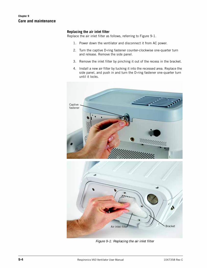
Chapter 9
9-4 Respironics V60 Ventilator User Manual 1047358 Rev C
Care and maintenance
Replacing the air inlet filterReplace the air inlet filter as follows, referring to Figure 9-1.
1. Power down the ventilator and disconnect it from AC power.
2. Turn the captive D-ring fastener counter-clockwise one-quarter turn and release. Remove the side panel.
3. Remove the inlet filter by pinching it out of the recess in the bracket.
4. Install a new air filter by tucking it into the recessed area. Replace the side panel, and push in and turn the D-ring fastener one-quarter turn until it locks.
Figure 9-1: Replacing the air inlet filter
Air inlet filter Bracket
Captive fastener
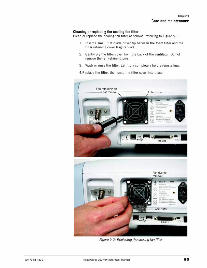
Chapter 9
Care and maintenance
1047358 Rev C Respironics V60 Ventilator User Manual 9-5
Cleaning or replacing the cooling fan filterClean or replace the cooling fan filter as follows, referring to Figure 9-2:
1. Insert a small, flat blade driver tip between the foam filter and the filter retaining cover (Figure 9-2).
2. Gently pry the filter cover from the back of the ventilator. Do not remove the fan retaining pins.
3. Wash or rinse the filter. Let it dry completely before reinstalling.
4.Replace the filter, then snap the filter cover into place.
Figure 9-2: Replacing the cooling fan filter
Filter cover
Foam filter
Fan (Do not remove)
Fan retaining pin(Do not remove)
Chapter 9
9-6 Respironics V60 Ventilator User Manual 1047358 Rev C
Care and maintenance
Removing and replacing the batterySee “Installing the optional battery” on page A-3.
Disposal Dispose of all parts removed from the device according to your institution’s protocol. Follow all local, state, and federal regulations with respect to environmental protection, especially when disposing of the electronic device or parts of it (for example, oxygen cell, batteries).
Storage See Table 10-8 on page 10-5 for ventilator storage requirements.
Repairs For technical service or repair information not included in this chapter, contact Respironics.
Repacking and shipping
CAUTION: To prevent possible damage to the ventilator, always ship it with the original packing material. If the original material is not available, contact Respironics to order replacements.
NOTE: Transport of lithium ion batteries is strictly controlled by international regulations and laws. Do not ship the battery either in the ventilator or separately by sea or air. Contact your Respironics representative to obtain appropriate packaging for ground trasnport of batteries.
Remove the battery from the ventilator before shipping the ventilator. See “Installing the optional battery” on page A-3 for more information. Ship the battery and ventilator separately in appropriate packaging in conformance with federal, state, and local regulations. Contact Respironics to obtain appropriate ventilator or battery packaging.
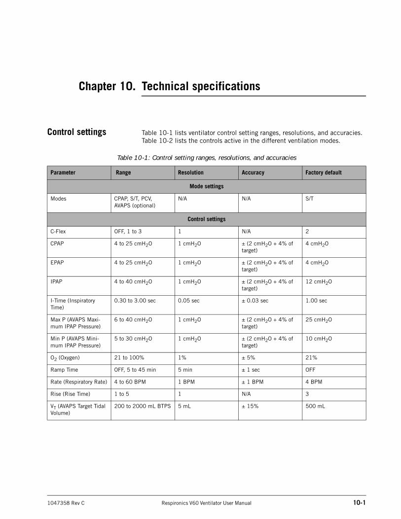
1047358 Rev C Respironics V60 Ventilator User Manual 10-1
Chapter 10. Technical specifications
Control settings Table 10-1 lists ventilator control setting ranges, resolutions, and accuracies. Table 10-2 lists the controls active in the different ventilation modes.
Table 10-1: Control setting ranges, resolutions, and accuracies
Parameter Range Resolution Accuracy Factory default
Mode settings
Modes CPAP, S/T, PCV, AVAPS (optional)
N/A N/A S/T
Control settings
C-Flex OFF, 1 to 3 1 N/A 2
CPAP 4 to 25 cmH2O 1 cmH2O ± (2 cmH2O + 4% of target)
4 cmH2O
EPAP 4 to 25 cmH2O 1 cmH2O ± (2 cmH2O + 4% of target)
4 cmH2O
IPAP 4 to 40 cmH2O 1 cmH2O ± (2 cmH2O + 4% of target)
12 cmH2O
I-Time (Inspiratory Time)
0.30 to 3.00 sec 0.05 sec ± 0.03 sec 1.00 sec
Max P (AVAPS Maxi-mum IPAP Pressure)
6 to 40 cmH2O 1 cmH2O ± (2 cmH2O + 4% of target)
25 cmH2O
Min P (AVAPS Mini-mum IPAP Pressure)
5 to 30 cmH2O 1 cmH2O ± (2 cmH2O + 4% of target)
10 cmH2O
O2 (Oxygen) 21 to 100% 1% ± 5% 21%
Ramp Time OFF, 5 to 45 min 5 min ± 1 sec OFF
Rate (Respiratory Rate) 4 to 60 BPM 1 BPM ± 1 BPM 4 BPM
Rise (Rise Time) 1 to 5 1 N/A 3
VT (AVAPS Target Tidal Volume)
200 to 2000 mL BTPS 5 mL ± 15% 500 mL
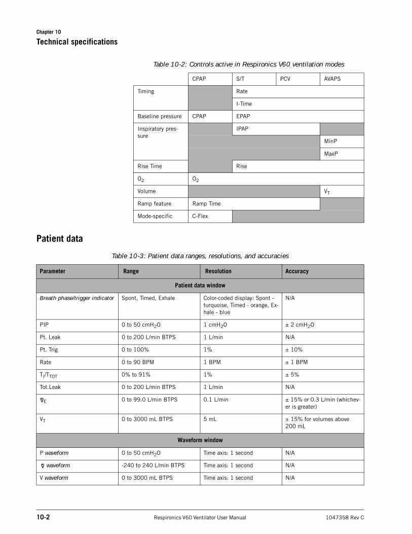
Chapter 10
10-2 Respironics V60 Ventilator User Manual 1047358 Rev C
Technical specifications
Patient data
Table 10-2: Controls active in Respironics V60 ventilation modes
CPAP S/T PCV AVAPS
Timing Rate
I-Time
Baseline pressure CPAP EPAP
Inspiratory pres-sure
IPAP
MinP
MaxP
Rise Time Rise
O2 O2
Volume VT
Ramp feature Ramp Time
Mode-specific C-Flex
Table 10-3: Patient data ranges, resolutions, and accuracies
Parameter Range Resolution Accuracy
Patient data window
Breath phase/trigger indicator Spont, Timed, Exhale Color-coded display: Spont - turquoise, Timed - orange, Ex-hale - blue
N/A
PIP 0 to 50 cmH2O 1 cmH2O ± 2 cmH2O
Pt. Leak 0 to 200 L/min BTPS 1 L/min N/A
Pt. Trig 0 to 100% 1% ± 10%
Rate 0 to 90 BPM 1 BPM ± 1 BPM
TI/TTOT 0% to 91% 1% ± 5%
Tot.Leak 0 to 200 L/min BTPS 1 L/min N/A
E 0 to 99.0 L/min BTPS 0.1 L/min ± 15% or 0.3 L/min (whichev-er is greater)
VT 0 to 3000 mL BTPS 5 mL ± 15% for volumes above 200 mL
Waveform window
P waveform 0 to 50 cmH2O Time axis: 1 second N/A
waveform -240 to 240 L/min BTPS Time axis: 1 second N/A
V waveform 0 to 3000 mL BTPS Time axis: 1 second N/A
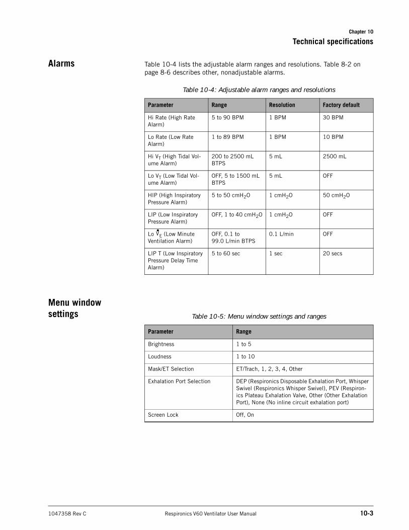
Chapter 10
Technical specifications
1047358 Rev C Respironics V60 Ventilator User Manual 10-3
Alarms Table 10-4 lists the adjustable alarm ranges and resolutions. Table 8-2 on page 8-6 describes other, nonadjustable alarms.
Menu window settings
Table 10-4: Adjustable alarm ranges and resolutions
Parameter Range Resolution Factory default
Hi Rate (High Rate Alarm)
5 to 90 BPM 1 BPM 30 BPM
Lo Rate (Low Rate Alarm)
1 to 89 BPM 1 BPM 10 BPM
Hi VT (High Tidal Vol-ume Alarm)
200 to 2500 mL BTPS
5 mL 2500 mL
Lo VT (Low Tidal Vol-ume Alarm)
OFF, 5 to 1500 mL BTPS
5 mL OFF
HIP (High Inspiratory Pressure Alarm)
5 to 50 cmH2O 1 cmH2O 50 cmH2O
LIP (Low Inspiratory Pressure Alarm)
OFF, 1 to 40 cmH2O 1 cmH2O OFF
Lo E (Low Minute Ventilation Alarm)
OFF, 0.1 to99.0 L/min BTPS
0.1 L/min OFF
LIP T (Low Inspiratory Pressure Delay Time Alarm)
5 to 60 sec 1 sec 20 secs
V•
Table 10-5: Menu window settings and ranges
Parameter Range
Brightness 1 to 5
Loudness 1 to 10
Mask/ET Selection ET/Trach, 1, 2, 3, 4, Other
Exhalation Port Selection DEP (Respironics Disposable Exhalation Port, Whisper Swivel (Respironics Whisper Swivel), PEV (Respiron-ics Plateau Exhalation Valve, Other (Other Exhalation Port), None (No inline circuit exhalation port)
Screen Lock Off, On
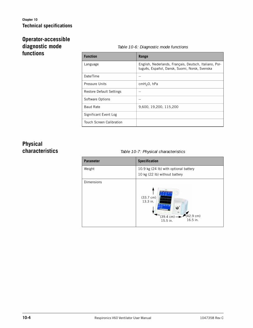
Chapter 10
10-4 Respironics V60 Ventilator User Manual 1047358 Rev C
Technical specifications
Operator-accessible diagnostic mode functions
Physical characteristics
Table 10-6: Diagnostic mode functions
Function Range
Language English, Nederlands, Français, Deutsch, Italiano, Por-tuguês, Español, Dansk, Suomi, Norsk, Svenska
Date/Time --
Pressure Units cmH2O, hPa
Restore Default Settings --
Software Options --
Baud Rate 9,600, 19,200, 115,200
Significant Event Log
Touch Screen Calibration
Table 10-7: Physical characteristics
Parameter Specification
Weight 10.9 kg (24 lb) with optional battery
10 kg (22 lb) without battery
Dimensions
(39.4 cm)15.5 in.
(42.9 cm)16.5 in.
(33.7 cm)13.3 in.
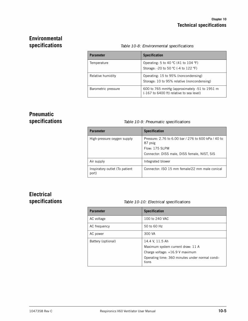
Chapter 10
Technical specifications
1047358 Rev C Respironics V60 Ventilator User Manual 10-5
Environmental specifications
Pneumatic specifications
Electrical specifications
Table 10-8: Environmental specifications
Parameter Specification
Temperature Operating: 5 to 40 ºC (41 to 104 ºF)
Storage: -20 to 50 ºC (-4 to 122 ºF)
Relative humidity Operating: 15 to 95% (noncondensing)
Storage: 10 to 95% relative (noncondensing)
Barometric pressure 600 to 765 mmHg (approximately -51 to 1951 m(-167 to 6400 ft) relative to sea level)
Table 10-9: Pneumatic specifications
Parameter Specification
High-pressure oxygen supply Pressure: 2.76 to 6.00 bar / 276 to 600 kPa / 40 to 87 psig
Flow: 175 SLPM
Connector: DISS male, DISS female, NIST, SIS
Air supply Integrated blower
Inspiratory outlet (To patient port)
Connector: ISO 15 mm female/22 mm male conical
Table 10-10: Electrical specifications
Parameter Specification
AC voltage 100 to 240 VAC
AC frequency 50 to 60 Hz
AC power 300 VA
Battery (optional) 14.4 V, 11.5 Ah
Maximum system current draw: 11 A
Charge voltage: +16.9 V maximum
Operating time: 360 minutes under normal condi-tions
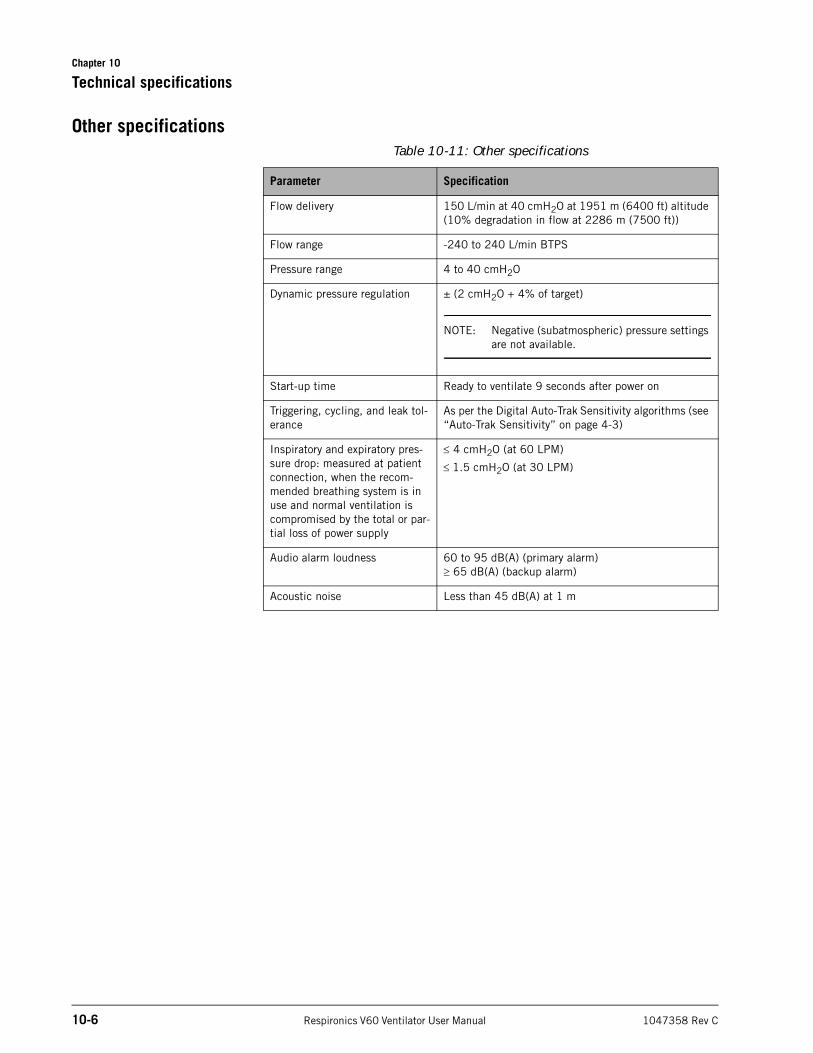
Chapter 10
10-6 Respironics V60 Ventilator User Manual 1047358 Rev C
Technical specifications
Other specificationsTable 10-11: Other specifications
Parameter Specification
Flow delivery 150 L/min at 40 cmH2O at 1951 m (6400 ft) altitude (10% degradation in flow at 2286 m (7500 ft))
Flow range -240 to 240 L/min BTPS
Pressure range 4 to 40 cmH2O
Dynamic pressure regulation ± (2 cmH2O + 4% of target)
NOTE: Negative (subatmospheric) pressure settings are not available.
Start-up time Ready to ventilate 9 seconds after power on
Triggering, cycling, and leak tol-erance
As per the Digital Auto-Trak Sensitivity algorithms (see “Auto-Trak Sensitivity” on page 4-3)
Inspiratory and expiratory pres-sure drop: measured at patient connection, when the recom-mended breathing system is in use and normal ventilation is compromised by the total or par-tial loss of power supply
4 cmH2O (at 60 LPM)
1.5 cmH2O (at 30 LPM)
Audio alarm loudness 60 to 95 dB(A) (primary alarm) 65 dB(A) (backup alarm)
Acoustic noise Less than 45 dB(A) at 1 m
1047358 Rev C Respironics V60 Ventilator User Manual A-1
Appendix A. First-time installation
Before putting the ventilator into service for the first time, install it as described in this chapter.
Unpacking and inspection
Unpack the ventilator and inspect it for damage. Inspect the exterior cabinet of the ventilator for cracks, scratches, or blemishes. Inspect the front panel for scratches or abrasions. Correct and/or report any problems found to Respironics before using the ventilator.
Before using the ventilator the first time, we recommend wiping the exterior clean and disinfecting components according to the instructions in Chapter 9.
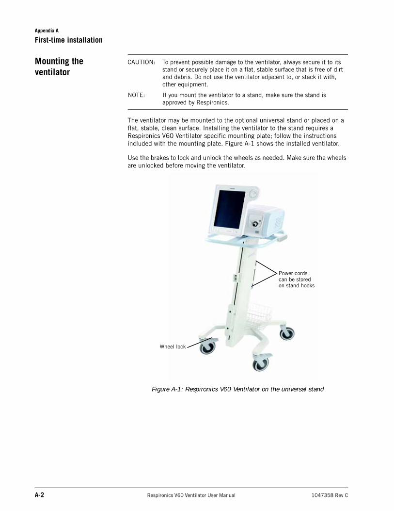
Appendix A
A-2 Respironics V60 Ventilator User Manual 1047358 Rev C
First-time installation
Mounting the ventilator
CAUTION: To prevent possible damage to the ventilator, always secure it to its stand or securely place it on a flat, stable surface that is free of dirt and debris. Do not use the ventilator adjacent to, or stack it with, other equipment.
NOTE: If you mount the ventilator to a stand, make sure the stand is approved by Respironics.
The ventilator may be mounted to the optional universal stand or placed on a flat, stable, clean surface. Installing the ventilator to the stand requires a Respironics V60 Ventilator specific mounting plate; follow the instructions included with the mounting plate. Figure A-1 shows the installed ventilator.
Use the brakes to lock and unlock the wheels as needed. Make sure the wheels are unlocked before moving the ventilator.
Figure A-1: Respironics V60 Ventilator on the universal stand
Power cords can be stored on stand hooks
Wheel lock
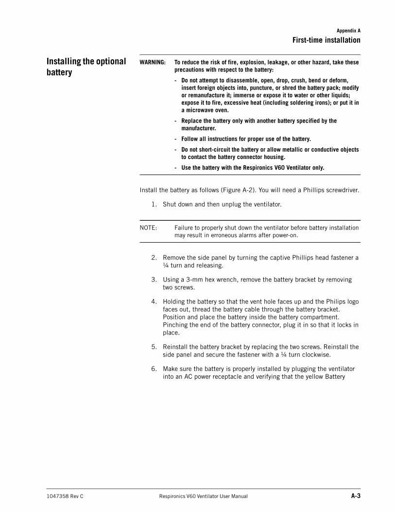
Appendix A
First-time installation
1047358 Rev C Respironics V60 Ventilator User Manual A-3
Installing the optional battery
WARNING: To reduce the risk of fire, explosion, leakage, or other hazard, take these precautions with respect to the battery:
- Do not attempt to disassemble, open, drop, crush, bend or deform, insert foreign objects into, puncture, or shred the battery pack; modify or remanufacture it; immerse or expose it to water or other liquids; expose it to fire, excessive heat (including soldering irons); or put it in a microwave oven.
- Replace the battery only with another battery specified by the manufacturer.
- Follow all instructions for proper use of the battery.
- Do not short-circuit the battery or allow metallic or conductive objects to contact the battery connector housing.
- Use the battery with the Respironics V60 Ventilator only.
Install the battery as follows (Figure A-2). You will need a Phillips screwdriver.
1. Shut down and then unplug the ventilator.
NOTE: Failure to properly shut down the ventilator before battery installation may result in erroneous alarms after power-on.
2. Remove the side panel by turning the captive Phillips head fastener a ¼ turn and releasing.
3. Using a 3-mm hex wrench, remove the battery bracket by removing two screws.
4. Holding the battery so that the vent hole faces up and the Philips logo faces out, thread the battery cable through the battery bracket. Position and place the battery inside the battery compartment. Pinching the end of the battery connector, plug it in so that it locks in place.
5. Reinstall the battery bracket by replacing the two screws. Reinstall the side panel and secure the fastener with a ¼ turn clockwise.
6. Make sure the battery is properly installed by plugging the ventilator into an AC power receptacle and verifying that the yellow Battery
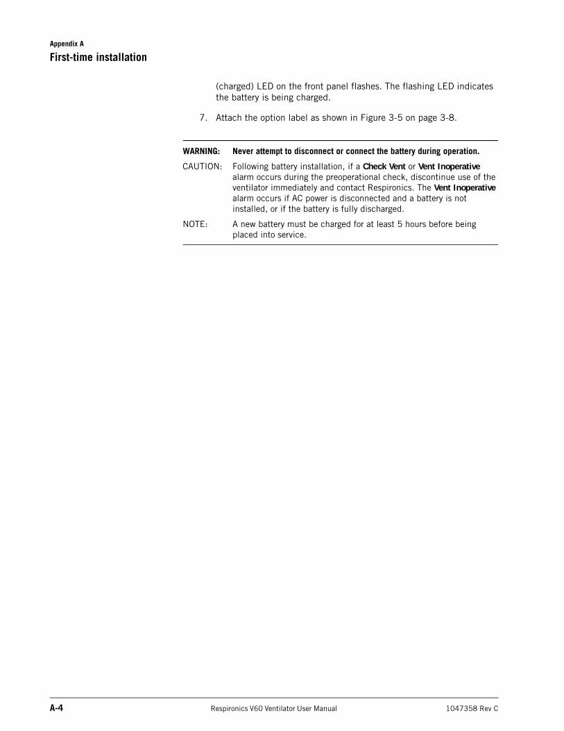
Appendix A
A-4 Respironics V60 Ventilator User Manual 1047358 Rev C
First-time installation
(charged) LED on the front panel flashes. The flashing LED indicates the battery is being charged.
7. Attach the option label as shown in Figure 3-5 on page 3-8.
WARNING: Never attempt to disconnect or connect the battery during operation.
CAUTION: Following battery installation, if a Check Vent or Vent Inoperative alarm occurs during the preoperational check, discontinue use of the ventilator immediately and contact Respironics. The Vent Inoperative alarm occurs if AC power is disconnected and a battery is not installed, or if the battery is fully discharged.
NOTE: A new battery must be charged for at least 5 hours before being placed into service.
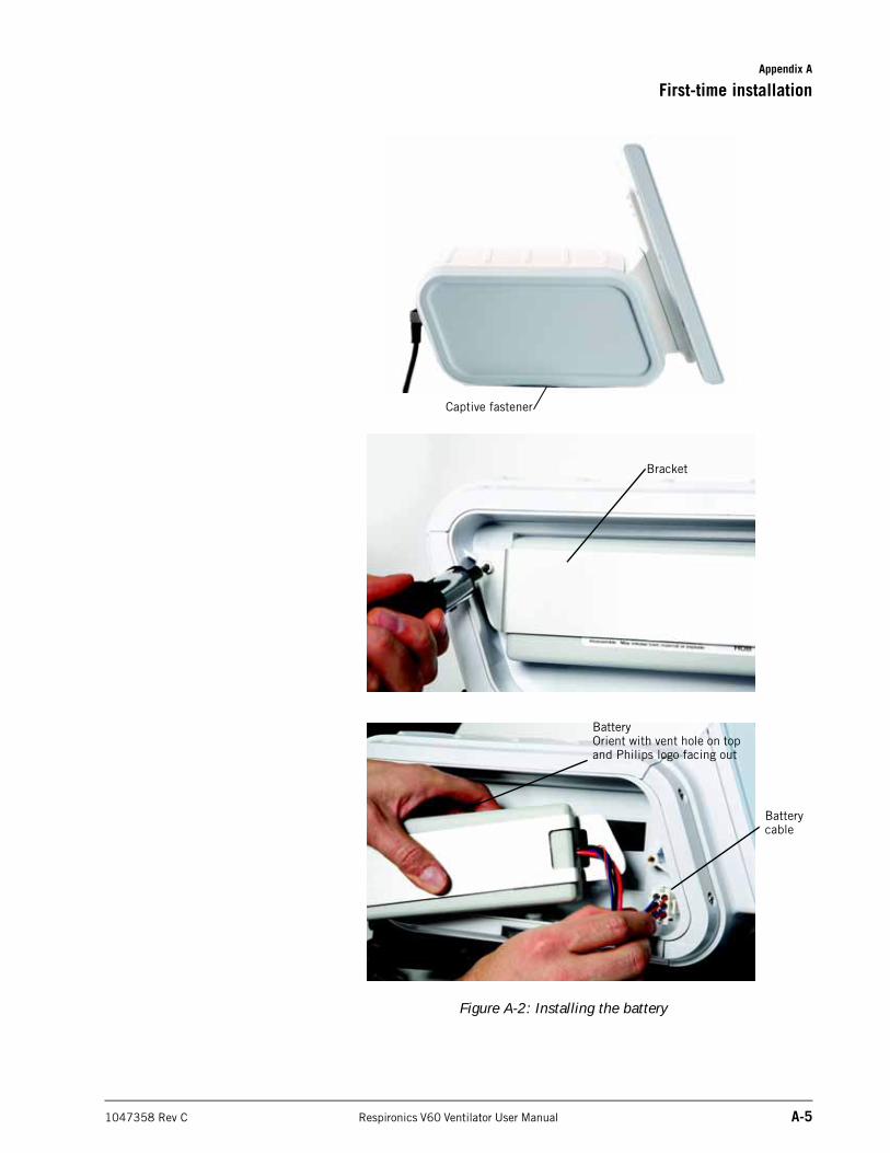
Appendix A
First-time installation
1047358 Rev C Respironics V60 Ventilator User Manual A-5
Figure A-2: Installing the battery
Captive fastener
Bracket
Batterycable
BatteryOrient with vent hole on top and Philips logo facing out
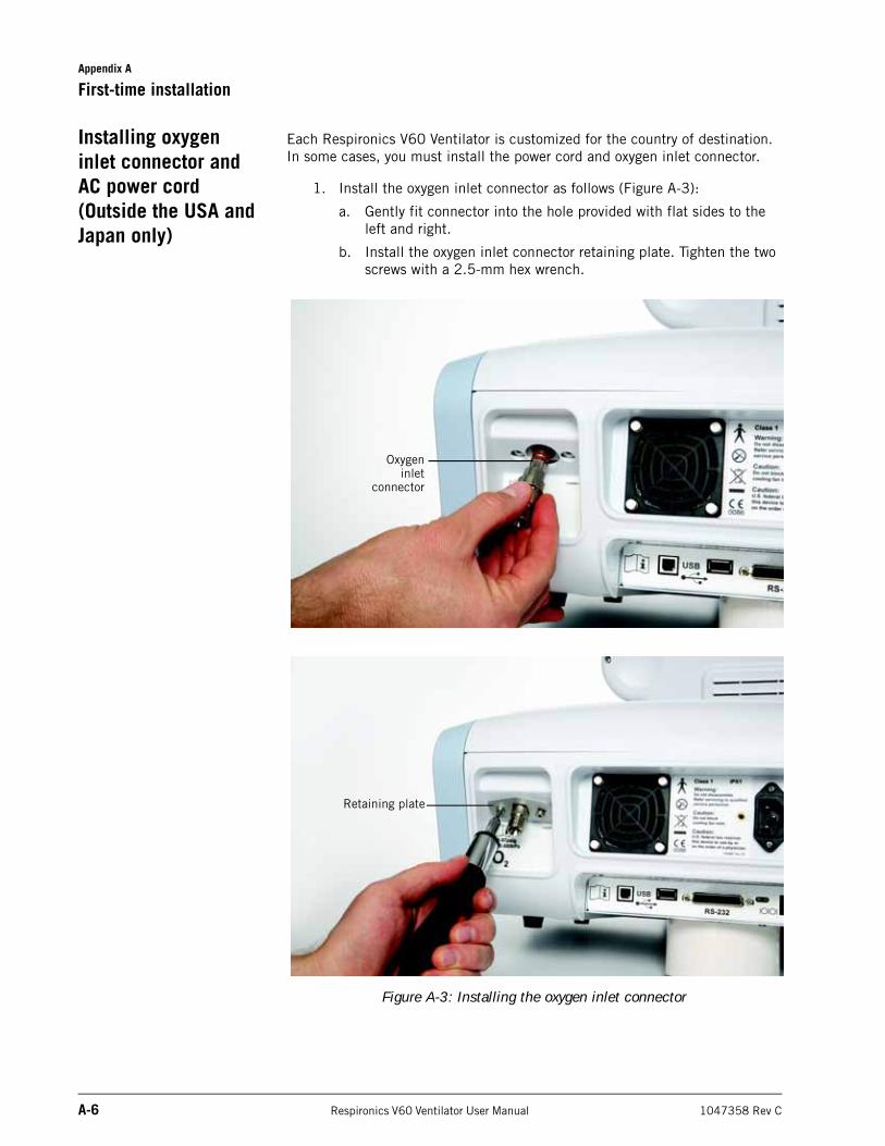
Appendix A
A-6 Respironics V60 Ventilator User Manual 1047358 Rev C
First-time installation
Installing oxygen inlet connector and AC power cord (Outside the USA and Japan only)
Each Respironics V60 Ventilator is customized for the country of destination. In some cases, you must install the power cord and oxygen inlet connector.
1. Install the oxygen inlet connector as follows (Figure A-3):
a. Gently fit connector into the hole provided with flat sides to the left and right.
b. Install the oxygen inlet connector retaining plate. Tighten the two screws with a 2.5-mm hex wrench.
Figure A-3: Installing the oxygen inlet connector
Retaining plate
Oxygeninlet
connector
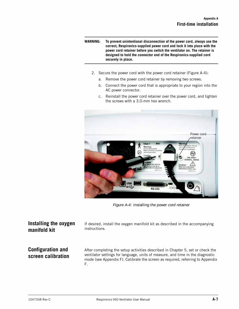
Appendix A
First-time installation
1047358 Rev C Respironics V60 Ventilator User Manual A-7
WARNING: To prevent unintentional disconnection of the power cord, always use the correct, Respironics-supplied power cord and lock it into place with the power cord retainer before you switch the ventilator on. The retainer is designed to hold the connector end of the Respironics-supplied cord securely in place.
2. Secure the power cord with the power cord retainer (Figure A-4):
a. Remove the power cord retainer by removing two screws.
b. Connect the power cord that is appropriate to your region into the AC power connector.
c. Reinstall the power cord retainer over the power cord, and tighten the screws with a 3.0-mm hex wrench.
Figure A-4: Installing the power cord retainer
Installing the oxygen manifold kit
If desired, install the oxygen manifold kit as described in the accompanying instructions.
Configuration and screen calibration
After completing the setup activities described in Chapter 5, set or check the ventilator settings for language, units of measure, and time in the diagnostic mode (see Appendix F). Calibrate the screen as required, referring to Appendix F.
Power cord retainer

Appendix A
A-8 Respironics V60 Ventilator User Manual 1047358 Rev C
First-time installation
(This page is intentionally blank.)
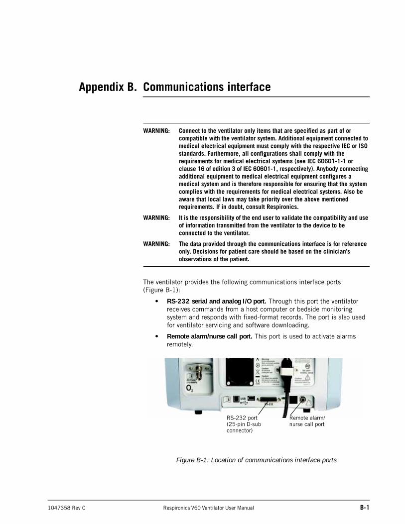
1047358 Rev C Respironics V60 Ventilator User Manual B-1
Appendix B. Communications interface
WARNING: Connect to the ventilator only items that are specified as part of or compatible with the ventilator system. Additional equipment connected to medical electrical equipment must comply with the respective IEC or ISO standards. Furthermore, all configurations shall comply with the requirements for medical electrical systems (see IEC 60601-1-1 or clause 16 of edition 3 of IEC 60601-1, respectively). Anybody connecting additional equipment to medical electrical equipment configures a medical system and is therefore responsible for ensuring that the system complies with the requirements for medical electrical systems. Also be aware that local laws may take priority over the above mentioned requirements. If in doubt, consult Respironics.
WARNING: It is the responsibility of the end user to validate the compatibility and use of information transmitted from the ventilator to the device to be connected to the ventilator.
WARNING: The data provided through the communications interface is for reference only. Decisions for patient care should be based on the clinician’s observations of the patient.
The ventilator provides the following communications interface ports (Figure B-1):
• RS-232 serial and analog I/O port. Through this port the ventilator receives commands from a host computer or bedside monitoring system and responds with fixed-format records. The port is also used for ventilator servicing and software downloading.
• Remote alarm/nurse call port. This port is used to activate alarms remotely.
Figure B-1: Location of communications interface ports
Remote alarm/nurse call port
RS-232 port(25-pin D-sub connector)
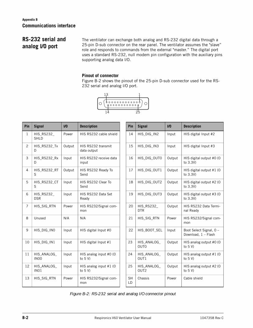
Appendix B
B-2 Respironics V60 Ventilator User Manual 1047358 Rev C
Communications interface
RS-232 serial and analog I/O port
The ventilator can exchange both analog and RS-232 digital data through a 25-pin D-sub connector on the rear panel. The ventilator assumes the "slave” role and responds to commands from the external "master.” The digital port uses a standard RS-232, null modem pin configuration with the auxiliary pins supporting analog data I/O.
Pinout of connectorFigure B-2 shows the pinout of the 25-pin D-sub connector used for the RS-232 serial and analog I/O port.
Figure B-2: RS-232 serial and analog I/O connector pinout
Pin Signal I/O Description Pin Signal I/O Description
1 HIS_RS232_SHLD
Power HIS RS232 cable shield 14 HIS_DIG_IN2 Input HIS digital Input #2
2 HIS_RS232_TxD
Output HIS RS232 transmit data output
15 HIS_DIG_IN3 Input HIS digital Input #3
3 HIS_RS232_RxD
Input HIS RS232 receive data input
16 HIS_DIG_OUT0 Output HIS digital output #0 (0 to 3.3V)
4 HIS_RS232_RTS
Output HIS RS232 Ready To Send
17 HIS_DIG_OUT1 Output HIS digital output #1 (0 to 3.3V)
5 HIS_RS232_CTS
Input HIS RS232 Clear To Send
18 HIS_DIG_OUT2 Output HIS digital output #2 (0 to 3.3V)
6 HIS_RS232_DSR
Input HIS RS232 Data Set Ready
19 HIS_DIG_OUT3 Output HIS digital output #3 (0 to 3.3V)
7 HIS_SIG_RTN Power HIS RS232/Signal com-mon
20 HIS_RS232_DTR
Output HIS RS232 Data Termi-nal Ready
8 Unused N/A N/A 21 HIS_SIG_RTN Power HIS RS232/Signal com-mon
9 HIS_DIG_IN0 Input HIS digital Input #0 22 HIS_BOOT_SEL Input Boot Select Signal, 0 – Download, 1 – Flash
10 HIS_DIG_IN1 Input HIS digital Input #1 23 HIS_ANALOG_OUT0
Output HIS analog output #0 (0 to 5 V)
11 HIS_ANALOG_IN00
Input HIS analog input #0 (0 to 5 V)
24 HIS_ANALOG_OUT1
Output HIS analog output #1 (0 to 5 V)
12 HIS_ANALOG_IN01
Input HIS analog input #1 (0 to 5 V)
25 HIS_ANALOG_OUT2
Output HIS analog output #2 (0 to 5 V)
13 HIS_SIG_RTN Power HIS RS232/Signal com-mon
SHLD
Chassis Power Cable shield
113
14 25
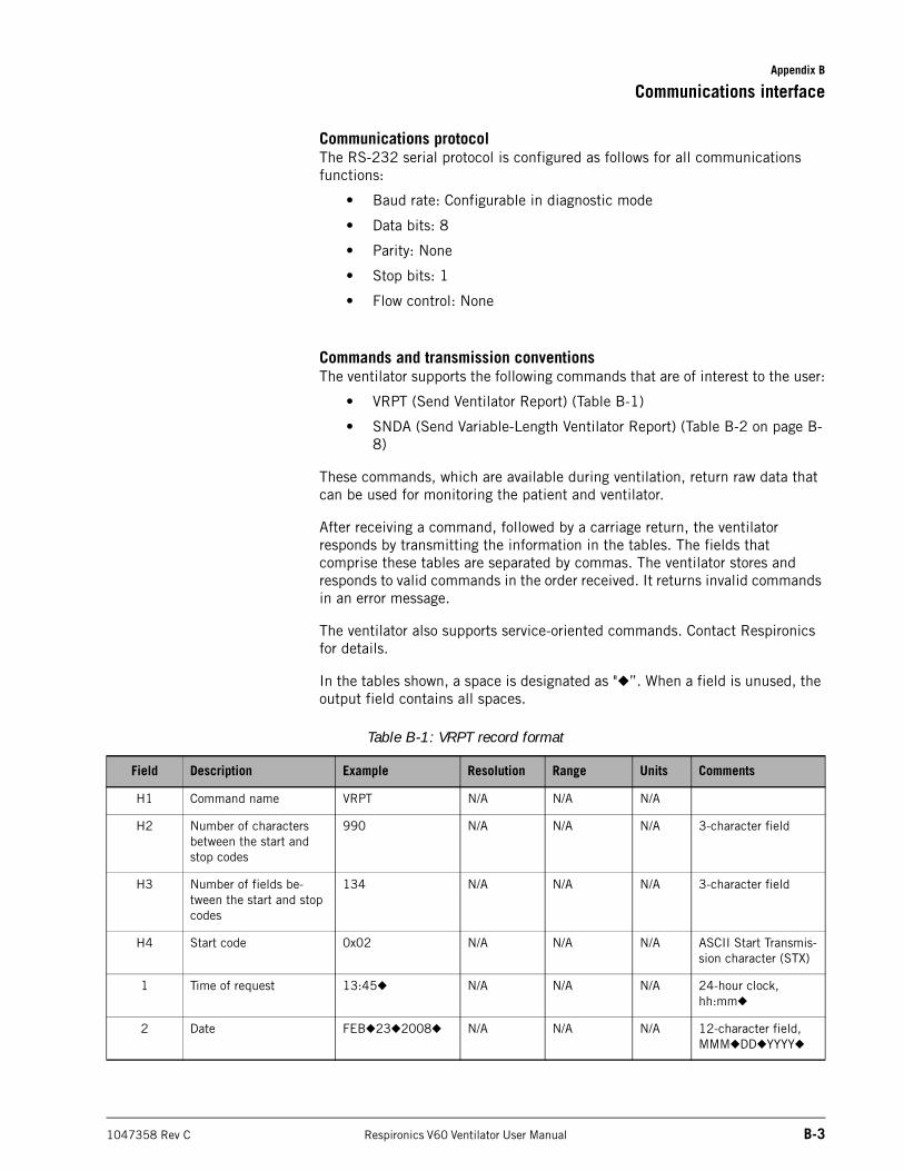
Appendix B
Communications interface
1047358 Rev C Respironics V60 Ventilator User Manual B-3
Communications protocolThe RS-232 serial protocol is configured as follows for all communications functions:
• Baud rate: Configurable in diagnostic mode
• Data bits: 8
• Parity: None
• Stop bits: 1
• Flow control: None
Commands and transmission conventionsThe ventilator supports the following commands that are of interest to the user:
• VRPT (Send Ventilator Report) (Table B-1)
• SNDA (Send Variable-Length Ventilator Report) (Table B-2 on page B-8)
These commands, which are available during ventilation, return raw data that can be used for monitoring the patient and ventilator.
After receiving a command, followed by a carriage return, the ventilator responds by transmitting the information in the tables. The fields that comprise these tables are separated by commas. The ventilator stores and responds to valid commands in the order received. It returns invalid commands in an error message.
The ventilator also supports service-oriented commands. Contact Respironics for details.
In the tables shown, a space is designated as "◆”. When a field is unused, the output field contains all spaces.
Table B-1: VRPT record format
Field Description Example Resolution Range Units Comments
H1 Command name VRPT N/A N/A N/A
H2 Number of characters between the start and stop codes
990 N/A N/A N/A 3-character field
H3 Number of fields be-tween the start and stop codes
134 N/A N/A N/A 3-character field
H4 Start code 0x02 N/A N/A N/A ASCII Start Transmis-sion character (STX)
1 Time of request 13:45◆ N/A N/A N/A 24-hour clock, hh:mm◆
2 Date FEB◆23◆2008◆ N/A N/A N/A 12-character field,MMM◆DD◆YYYY◆
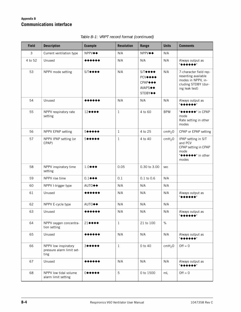
Appendix B
B-4 Respironics V60 Ventilator User Manual 1047358 Rev C
Communications interface
3 Current ventilation type NPPV◆◆ N/A NPPV◆◆ N/A
4 to 52 Unused ◆◆◆◆◆◆ N/A N/A N/A Always output as "◆◆◆◆◆◆"
53 NPPV mode setting S/T◆◆◆◆ N/A S/T◆◆◆◆
PCV◆◆◆◆
CPAP◆◆◆
AVAPS◆◆
STDBY◆◆
N/A 7-character field rep-resenting available modes in NPPV, in-cluding STDBY (dur-ing leak test)
54 Unused ◆◆◆◆◆◆ N/A N/A N/A Always output as "◆◆◆◆◆◆"
55 NPPV respiratory rate setting
12◆◆◆◆ 1 4 to 60 BPM "◆◆◆◆◆◆" in CPAP modeRate setting in other modes
56 NPPV EPAP setting 5◆◆◆◆◆ 1 4 to 25 cmH2O CPAP or EPAP setting
57 NPPV IPAP setting (or CPAP)
5◆◆◆◆◆ 1 4 to 40 cmH2O IPAP setting in S/T and PCVCPAP setting in CPAP mode"◆◆◆◆◆◆" in other modes
58 NPPV inspiratory time setting
1.0◆◆◆ 0.05 0.30 to 3.00 sec
59 NPPV rise time 0.1◆◆◆ 0.1 0.1 to 0.6 N/A
60 NPPV I-trigger type AUTO◆◆ N/A N/A N/A
61 Unused ◆◆◆◆◆◆ N/A N/A N/A Always output as "◆◆◆◆◆◆"
62 NPPV E-cycle type AUTO◆◆ N/A N/A N/A
63 Unused ◆◆◆◆◆◆ N/A N/A N/A Always output as "◆◆◆◆◆◆"
64 NPPV oxygen concentra-tion setting
21◆◆◆◆ 1 21 to 100 %
65 Unused ◆◆◆◆◆◆ N/A N/A N/A Always output as "◆◆◆◆◆◆"
66 NPPV low inspiratory pressure alarm limit set-ting
3◆◆◆◆◆ 1 0 to 40 cmH2O Off = 0
67 Unused ◆◆◆◆◆◆ N/A N/A N/A Always output as "◆◆◆◆◆◆"
68 NPPV low tidal volume alarm limit setting
0◆◆◆◆◆ 5 0 to 1500 mL Off = 0
Table B-1: VRPT record format (continued)
Field Description Example Resolution Range Units Comments
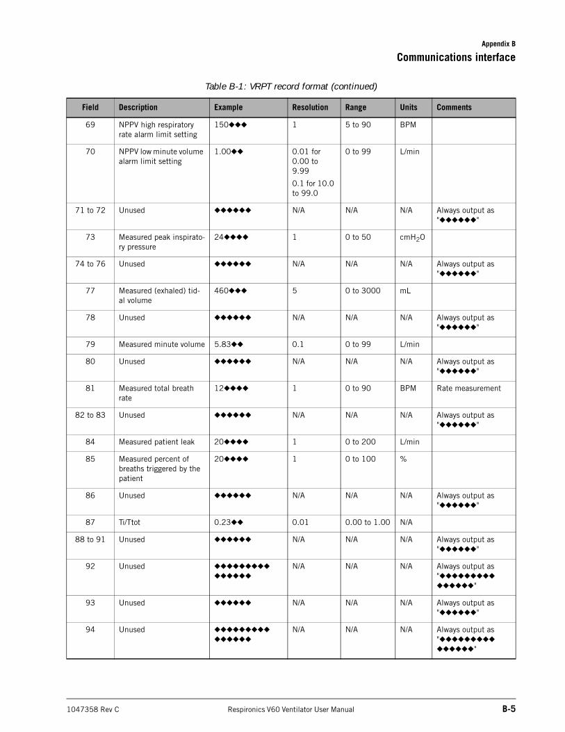
Appendix B
Communications interface
1047358 Rev C Respironics V60 Ventilator User Manual B-5
69 NPPV high respiratory rate alarm limit setting
150◆◆◆ 1 5 to 90 BPM
70 NPPV low minute volume alarm limit setting
1.00◆◆ 0.01 for 0.00 to 9.99
0.1 for 10.0 to 99.0
0 to 99 L/min
71 to 72 Unused ◆◆◆◆◆◆ N/A N/A N/A Always output as "◆◆◆◆◆◆"
73 Measured peak inspirato-ry pressure
24◆◆◆◆ 1 0 to 50 cmH2O
74 to 76 Unused ◆◆◆◆◆◆ N/A N/A N/A Always output as "◆◆◆◆◆◆"
77 Measured (exhaled) tid-al volume
460◆◆◆ 5 0 to 3000 mL
78 Unused ◆◆◆◆◆◆ N/A N/A N/A Always output as "◆◆◆◆◆◆"
79 Measured minute volume 5.83◆◆ 0.1 0 to 99 L/min
80 Unused ◆◆◆◆◆◆ N/A N/A N/A Always output as "◆◆◆◆◆◆"
81 Measured total breath rate
12◆◆◆◆ 1 0 to 90 BPM Rate measurement
82 to 83 Unused ◆◆◆◆◆◆ N/A N/A N/A Always output as "◆◆◆◆◆◆"
84 Measured patient leak 20◆◆◆◆ 1 0 to 200 L/min
85 Measured percent of breaths triggered by the patient
20◆◆◆◆ 1 0 to 100 %
86 Unused ◆◆◆◆◆◆ N/A N/A N/A Always output as "◆◆◆◆◆◆"
87 Ti/Ttot 0.23◆◆ 0.01 0.00 to 1.00 N/A
88 to 91 Unused ◆◆◆◆◆◆ N/A N/A N/A Always output as "◆◆◆◆◆◆"
92 Unused ◆◆◆◆◆◆◆◆◆
◆◆◆◆◆◆
N/A N/A N/A Always output as "◆◆◆◆◆◆◆◆◆
◆◆◆◆◆◆"
93 Unused ◆◆◆◆◆◆ N/A N/A N/A Always output as "◆◆◆◆◆◆"
94 Unused ◆◆◆◆◆◆◆◆◆
◆◆◆◆◆◆
N/A N/A N/A Always output as "◆◆◆◆◆◆◆◆◆
◆◆◆◆◆◆"
Table B-1: VRPT record format (continued)
Field Description Example Resolution Range Units Comments
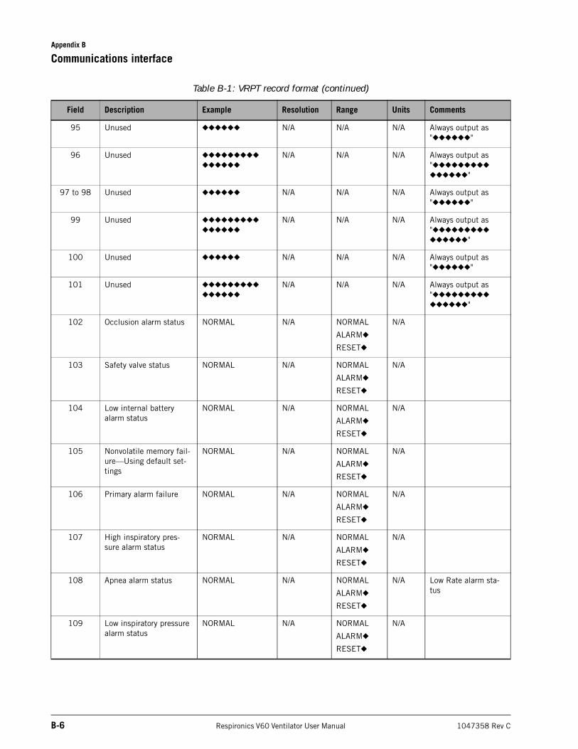
Appendix B
B-6 Respironics V60 Ventilator User Manual 1047358 Rev C
Communications interface
95 Unused ◆◆◆◆◆◆ N/A N/A N/A Always output as "◆◆◆◆◆◆"
96 Unused ◆◆◆◆◆◆◆◆◆
◆◆◆◆◆◆
N/A N/A N/A Always output as "◆◆◆◆◆◆◆◆◆
◆◆◆◆◆◆"
97 to 98 Unused ◆◆◆◆◆◆ N/A N/A N/A Always output as "◆◆◆◆◆◆"
99 Unused ◆◆◆◆◆◆◆◆◆
◆◆◆◆◆◆
N/A N/A N/A Always output as "◆◆◆◆◆◆◆◆◆
◆◆◆◆◆◆"
100 Unused ◆◆◆◆◆◆ N/A N/A N/A Always output as "◆◆◆◆◆◆"
101 Unused ◆◆◆◆◆◆◆◆◆
◆◆◆◆◆◆
N/A N/A N/A Always output as "◆◆◆◆◆◆◆◆◆
◆◆◆◆◆◆"
102 Occlusion alarm status NORMAL N/A NORMAL
ALARM◆
RESET◆
N/A
103 Safety valve status NORMAL N/A NORMAL
ALARM◆
RESET◆
N/A
104 Low internal battery alarm status
NORMAL N/A NORMAL
ALARM◆
RESET◆
N/A
105 Nonvolatile memory fail-ure—Using default set-tings
NORMAL N/A NORMAL
ALARM◆
RESET◆
N/A
106 Primary alarm failure NORMAL N/A NORMAL
ALARM◆
RESET◆
N/A
107 High inspiratory pres-sure alarm status
NORMAL N/A NORMAL
ALARM◆
RESET◆
N/A
108 Apnea alarm status NORMAL N/A NORMAL
ALARM◆
RESET◆
N/A Low Rate alarm sta-tus
109 Low inspiratory pressure alarm status
NORMAL N/A NORMAL
ALARM◆
RESET◆
N/A
Table B-1: VRPT record format (continued)
Field Description Example Resolution Range Units Comments
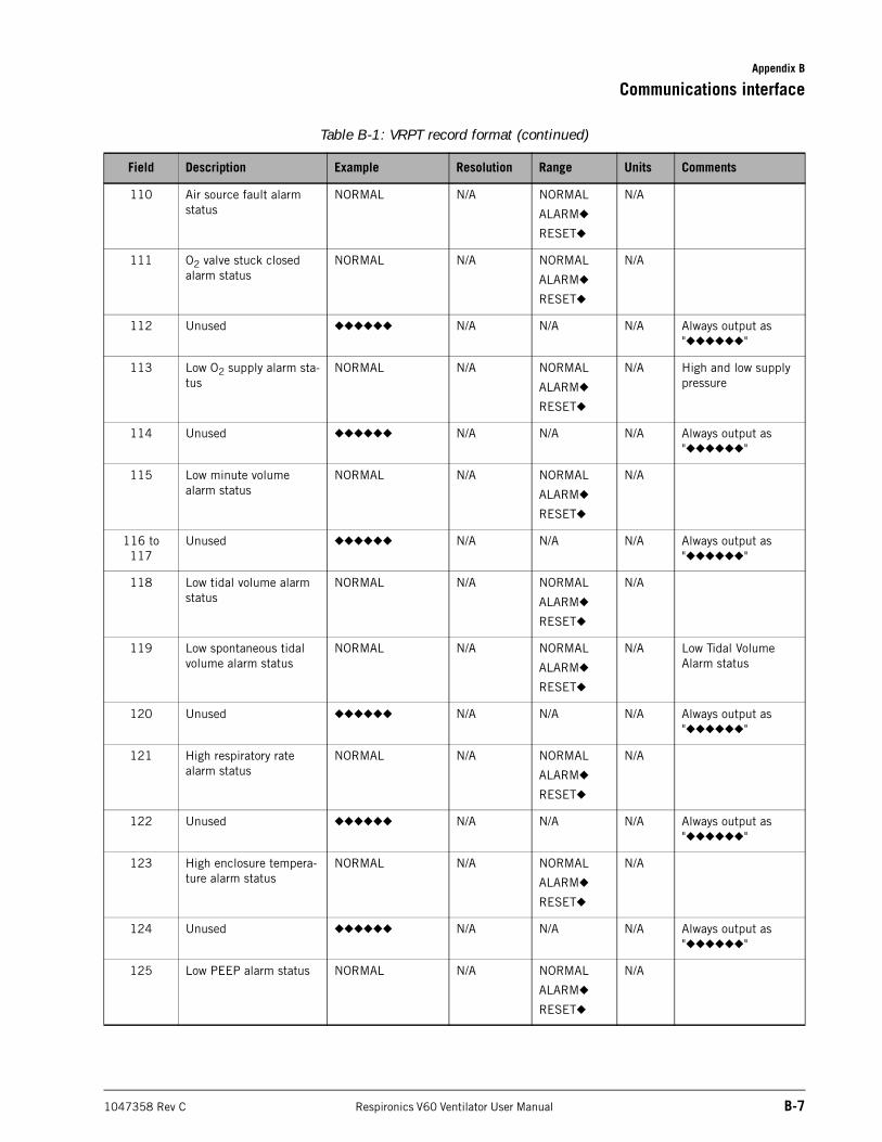
Appendix B
Communications interface
1047358 Rev C Respironics V60 Ventilator User Manual B-7
110 Air source fault alarm status
NORMAL N/A NORMAL
ALARM◆
RESET◆
N/A
111 O2 valve stuck closed alarm status
NORMAL N/A NORMAL
ALARM◆
RESET◆
N/A
112 Unused ◆◆◆◆◆◆ N/A N/A N/A Always output as "◆◆◆◆◆◆"
113 Low O2 supply alarm sta-tus
NORMAL N/A NORMAL
ALARM◆
RESET◆
N/A High and low supply pressure
114 Unused ◆◆◆◆◆◆ N/A N/A N/A Always output as "◆◆◆◆◆◆"
115 Low minute volume alarm status
NORMAL N/A NORMAL
ALARM◆
RESET◆
N/A
116 to 117
Unused ◆◆◆◆◆◆ N/A N/A N/A Always output as "◆◆◆◆◆◆"
118 Low tidal volume alarm status
NORMAL N/A NORMAL
ALARM◆
RESET◆
N/A
119 Low spontaneous tidal volume alarm status
NORMAL N/A NORMAL
ALARM◆
RESET◆
N/A Low Tidal Volume Alarm status
120 Unused ◆◆◆◆◆◆ N/A N/A N/A Always output as "◆◆◆◆◆◆"
121 High respiratory rate alarm status
NORMAL N/A NORMAL
ALARM◆
RESET◆
N/A
122 Unused ◆◆◆◆◆◆ N/A N/A N/A Always output as "◆◆◆◆◆◆"
123 High enclosure tempera-ture alarm status
NORMAL N/A NORMAL
ALARM◆
RESET◆
N/A
124 Unused ◆◆◆◆◆◆ N/A N/A N/A Always output as "◆◆◆◆◆◆"
125 Low PEEP alarm status NORMAL N/A NORMAL
ALARM◆
RESET◆
N/A
Table B-1: VRPT record format (continued)
Field Description Example Resolution Range Units Comments
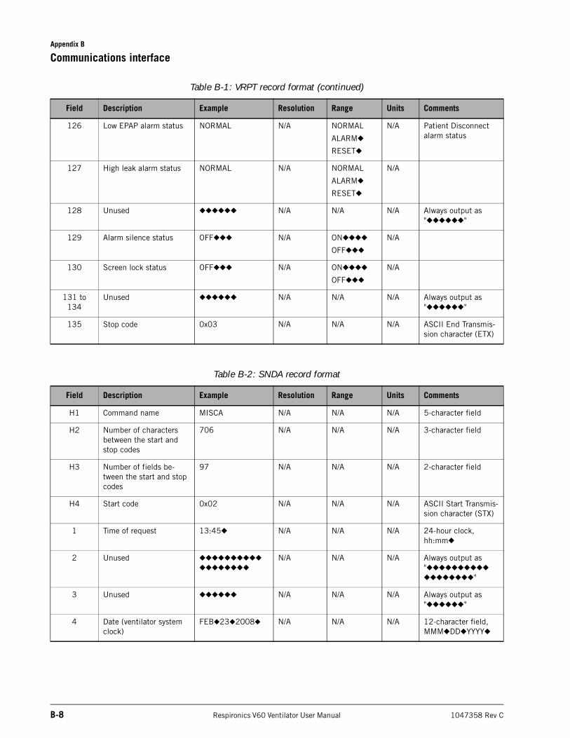
Appendix B
B-8 Respironics V60 Ventilator User Manual 1047358 Rev C
Communications interface
126 Low EPAP alarm status NORMAL N/A NORMAL
ALARM◆
RESET◆
N/A Patient Disconnect alarm status
127 High leak alarm status NORMAL N/A NORMAL
ALARM◆
RESET◆
N/A
128 Unused ◆◆◆◆◆◆ N/A N/A N/A Always output as "◆◆◆◆◆◆"
129 Alarm silence status OFF◆◆◆ N/A ON◆◆◆◆
OFF◆◆◆
N/A
130 Screen lock status OFF◆◆◆ N/A ON◆◆◆◆
OFF◆◆◆
N/A
131 to 134
Unused ◆◆◆◆◆◆ N/A N/A N/A Always output as "◆◆◆◆◆◆"
135 Stop code 0x03 N/A N/A N/A ASCII End Transmis-sion character (ETX)
Table B-2: SNDA record format
Field Description Example Resolution Range Units Comments
H1 Command name MISCA N/A N/A N/A 5-character field
H2 Number of characters between the start and stop codes
706 N/A N/A N/A 3-character field
H3 Number of fields be-tween the start and stop codes
97 N/A N/A N/A 2-character field
H4 Start code 0x02 N/A N/A N/A ASCII Start Transmis-sion character (STX)
1 Time of request 13:45◆ N/A N/A N/A 24-hour clock, hh:mm◆
2 Unused ◆◆◆◆◆◆◆◆◆◆
◆◆◆◆◆◆◆◆
N/A N/A N/A Always output as "◆◆◆◆◆◆◆◆◆◆
◆◆◆◆◆◆◆◆"
3 Unused ◆◆◆◆◆◆ N/A N/A N/A Always output as "◆◆◆◆◆◆"
4 Date (ventilator system clock)
FEB◆23◆2008◆ N/A N/A N/A 12-character field, MMM◆DD◆YYYY◆
Table B-1: VRPT record format (continued)
Field Description Example Resolution Range Units Comments
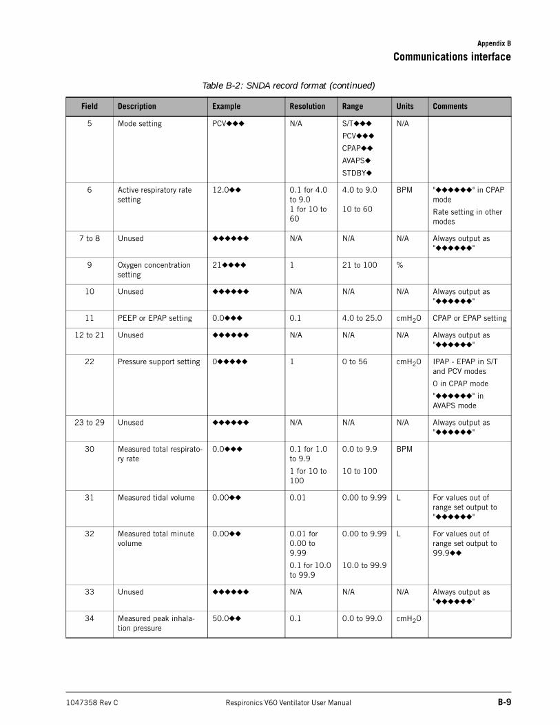
Appendix B
Communications interface
1047358 Rev C Respironics V60 Ventilator User Manual B-9
5 Mode setting PCV◆◆◆ N/A S/T◆◆◆
PCV◆◆◆
CPAP◆◆
AVAPS◆
STDBY◆
N/A
6 Active respiratory rate setting
12.0◆◆ 0.1 for 4.0 to 9.01 for 10 to 60
4.0 to 9.0
10 to 60
BPM "◆◆◆◆◆◆" in CPAP mode
Rate setting in other modes
7 to 8 Unused ◆◆◆◆◆◆ N/A N/A N/A Always output as "◆◆◆◆◆◆"
9 Oxygen concentration setting
21◆◆◆◆ 1 21 to 100 %
10 Unused ◆◆◆◆◆◆ N/A N/A N/A Always output as "◆◆◆◆◆◆"
11 PEEP or EPAP setting 0.0◆◆◆ 0.1 4.0 to 25.0 cmH2O CPAP or EPAP setting
12 to 21 Unused ◆◆◆◆◆◆ N/A N/A N/A Always output as "◆◆◆◆◆◆"
22 Pressure support setting 0◆◆◆◆◆ 1 0 to 56 cmH2O IPAP - EPAP in S/T and PCV modes
0 in CPAP mode
"◆◆◆◆◆◆" in AVAPS mode
23 to 29 Unused ◆◆◆◆◆◆ N/A N/A N/A Always output as "◆◆◆◆◆◆"
30 Measured total respirato-ry rate
0.0◆◆◆ 0.1 for 1.0 to 9.9
1 for 10 to 100
0.0 to 9.9
10 to 100
BPM
31 Measured tidal volume 0.00◆◆ 0.01 0.00 to 9.99 L For values out of range set output to "◆◆◆◆◆◆"
32 Measured total minute volume
0.00◆◆ 0.01 for 0.00 to 9.99
0.1 for 10.0 to 99.9
0.00 to 9.99
10.0 to 99.9
L For values out of range set output to 99.9◆◆
33 Unused ◆◆◆◆◆◆ N/A N/A N/A Always output as "◆◆◆◆◆◆"
34 Measured peak inhala-tion pressure
50.0◆◆ 0.1 0.0 to 99.0 cmH2O
Table B-2: SNDA record format (continued)
Field Description Example Resolution Range Units Comments
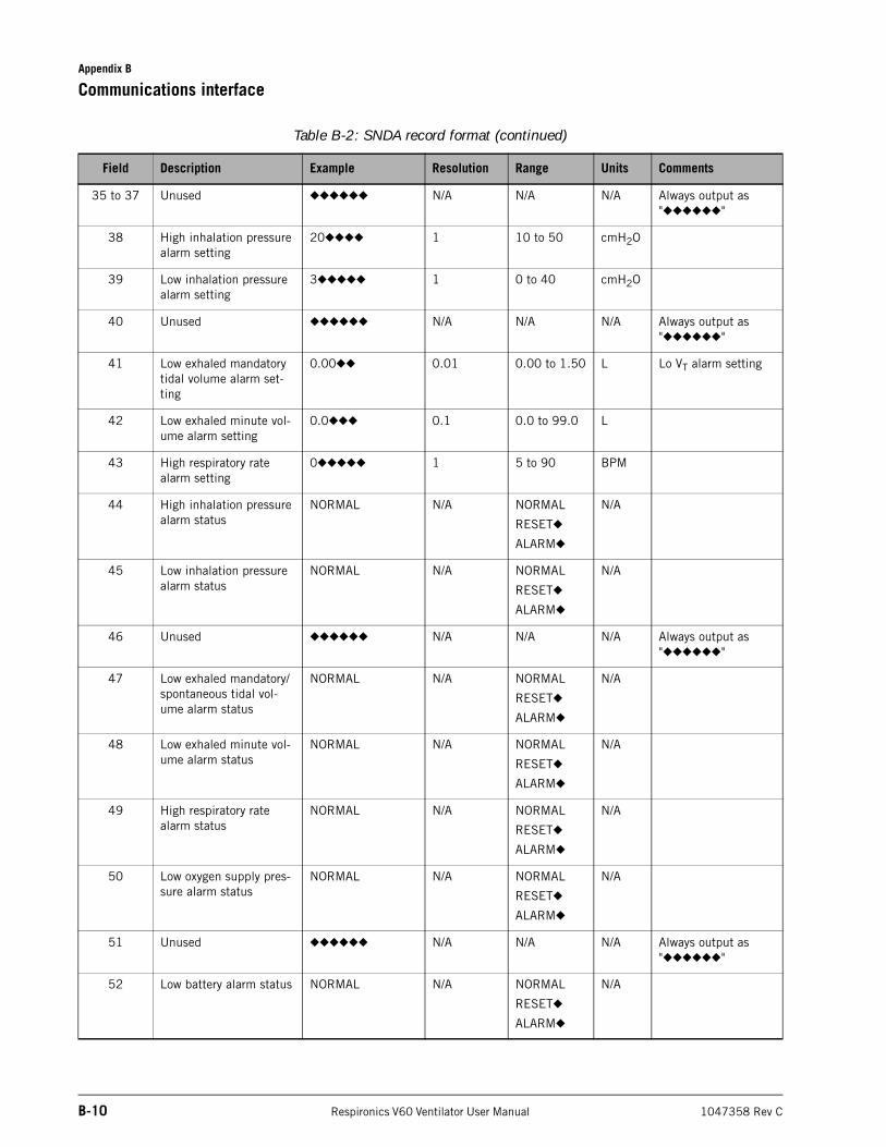
Appendix B
B-10 Respironics V60 Ventilator User Manual 1047358 Rev C
Communications interface
35 to 37 Unused ◆◆◆◆◆◆ N/A N/A N/A Always output as "◆◆◆◆◆◆"
38 High inhalation pressure alarm setting
20◆◆◆◆ 1 10 to 50 cmH2O
39 Low inhalation pressure alarm setting
3◆◆◆◆◆ 1 0 to 40 cmH2O
40 Unused ◆◆◆◆◆◆ N/A N/A N/A Always output as "◆◆◆◆◆◆"
41 Low exhaled mandatory tidal volume alarm set-ting
0.00◆◆ 0.01 0.00 to 1.50 L Lo VT alarm setting
42 Low exhaled minute vol-ume alarm setting
0.0◆◆◆ 0.1 0.0 to 99.0 L
43 High respiratory rate alarm setting
0◆◆◆◆◆ 1 5 to 90 BPM
44 High inhalation pressure alarm status
NORMAL N/A NORMAL
RESET◆
ALARM◆
N/A
45 Low inhalation pressure alarm status
NORMAL N/A NORMAL
RESET◆
ALARM◆
N/A
46 Unused ◆◆◆◆◆◆ N/A N/A N/A Always output as "◆◆◆◆◆◆"
47 Low exhaled mandatory/spontaneous tidal vol-ume alarm status
NORMAL N/A NORMAL
RESET◆
ALARM◆
N/A
48 Low exhaled minute vol-ume alarm status
NORMAL N/A NORMAL
RESET◆
ALARM◆
N/A
49 High respiratory rate alarm status
NORMAL N/A NORMAL
RESET◆
ALARM◆
N/A
50 Low oxygen supply pres-sure alarm status
NORMAL N/A NORMAL
RESET◆
ALARM◆
N/A
51 Unused ◆◆◆◆◆◆ N/A N/A N/A Always output as "◆◆◆◆◆◆"
52 Low battery alarm status NORMAL N/A NORMAL
RESET◆
ALARM◆
N/A
Table B-2: SNDA record format (continued)
Field Description Example Resolution Range Units Comments
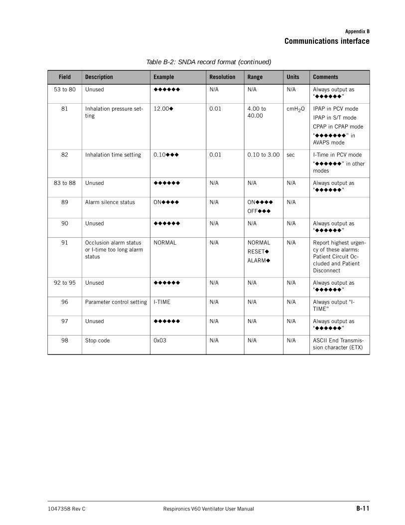
Appendix B
Communications interface
1047358 Rev C Respironics V60 Ventilator User Manual B-11
53 to 80 Unused ◆◆◆◆◆◆ N/A N/A N/A Always output as "◆◆◆◆◆◆”
81 Inhalation pressure set-ting
12.00◆ 0.01 4.00 to 40.00
cmH2O IPAP in PCV mode
IPAP in S/T mode
CPAP in CPAP mode
"◆◆◆◆◆◆◆” in AVAPS mode
82 Inhalation time setting 0.10◆◆◆ 0.01 0.10 to 3.00 sec I-Time in PCV mode
"◆◆◆◆◆◆” in other modes
83 to 88 Unused ◆◆◆◆◆◆ N/A N/A N/A Always output as "◆◆◆◆◆◆”
89 Alarm silence status ON◆◆◆◆ N/A ON◆◆◆◆
OFF◆◆◆
N/A
90 Unused ◆◆◆◆◆◆ N/A N/A N/A Always output as "◆◆◆◆◆◆”
91 Occlusion alarm status or I-time too long alarm status
NORMAL N/A NORMAL
RESET◆
ALARM◆
N/A Report highest urgen-cy of these alarms: Patient Circuit Oc-cluded and Patient Disconnect
92 to 95 Unused ◆◆◆◆◆◆ N/A N/A N/A Always output as "◆◆◆◆◆◆”
96 Parameter control setting I-TIME N/A N/A N/A Always output "I-TIME”
97 Unused ◆◆◆◆◆◆ N/A N/A N/A Always output as "◆◆◆◆◆◆”
98 Stop code 0x03 N/A N/A N/A ASCII End Transmis-sion character (ETX)
Table B-2: SNDA record format (continued)
Field Description Example Resolution Range Units Comments
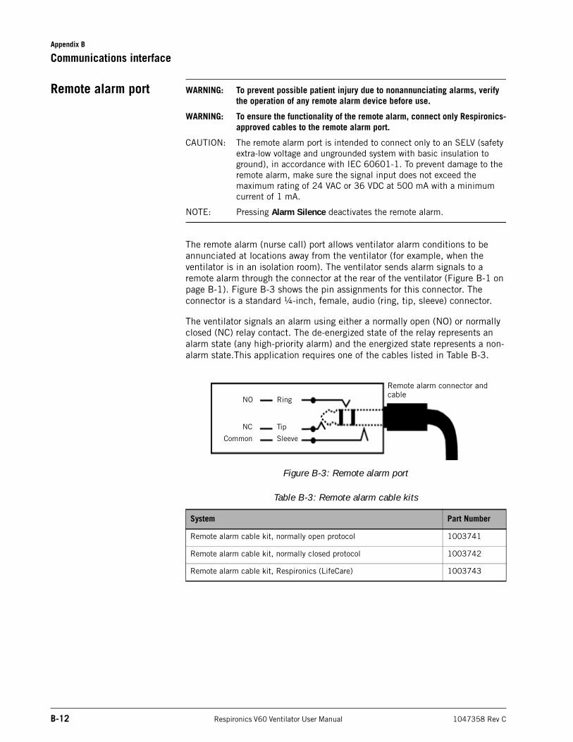
Appendix B
B-12 Respironics V60 Ventilator User Manual 1047358 Rev C
Communications interface
Remote alarm port WARNING: To prevent possible patient injury due to nonannunciating alarms, verify the operation of any remote alarm device before use.
WARNING: To ensure the functionality of the remote alarm, connect only Respironics-approved cables to the remote alarm port.
CAUTION: The remote alarm port is intended to connect only to an SELV (safety extra-low voltage and ungrounded system with basic insulation to ground), in accordance with IEC 60601-1. To prevent damage to the remote alarm, make sure the signal input does not exceed the maximum rating of 24 VAC or 36 VDC at 500 mA with a minimum current of 1 mA.
NOTE: Pressing Alarm Silence deactivates the remote alarm.
The remote alarm (nurse call) port allows ventilator alarm conditions to be annunciated at locations away from the ventilator (for example, when the ventilator is in an isolation room). The ventilator sends alarm signals to a remote alarm through the connector at the rear of the ventilator (Figure B-1 on page B-1). Figure B-3 shows the pin assignments for this connector. The connector is a standard ¼-inch, female, audio (ring, tip, sleeve) connector.
The ventilator signals an alarm using either a normally open (NO) or normally closed (NC) relay contact. The de-energized state of the relay represents an alarm state (any high-priority alarm) and the energized state represents a non-alarm state.This application requires one of the cables listed in Table B-3.
Figure B-3: Remote alarm port
Table B-3: Remote alarm cable kits
System Part Number
Remote alarm cable kit, normally open protocol 1003741
Remote alarm cable kit, normally closed protocol 1003742
Remote alarm cable kit, Respironics (LifeCare) 1003743
SleeveCommon
TipNC
RingNO
Remote alarm connector and cable
1047358 Rev C Respironics V60 Ventilator User Manual C-1
Appendix C. Warranty
One-year warranty Respironics warrants the Respironics V60 Ventilator to be free from defects in materials or workmanship for a period of one year from the date of delivery to the purchaser (the “warranty period”). If the product contains a defect in materials or workmanship and the product is returned to Respironics within the warranty period, Respironics will repair or replace the product, or issue a credit for the purchase price of the product, with the choice to repair, replace, or credit being within the sole discretion of Respironics. Respironics will pay customary freight charges from Respironics to the dealer location only. The foregoing repair, replacement, or credit remedy will be the sole remedy for breach of the foregoing warranty.
Without limiting the foregoing, this warranty does not cover damage to the product caused by accident, misuse, abuse, negligence, failure to install in accordance with Respironics’ installation instructions, failure to operate under conditions of normal use, and in accordance with the terms of the User Manual, failure to maintain in accordance with the applicable service manuals, alteration or any defects not related to materials or workmanship. This warranty does not cover damage which may occur in shipment. This warranty does not apply to any unit or individual parts which have been repaired or altered by anyone other than Respironics or an authorized Respironics service center. This warranty does not apply to products which are not purchased new.
Warranty limits Respironics does not make and hereby specifically disclaims all other warranties, express or implied, including without limitation, any implied warranty of merchantability or fitness for a particular purpose.
In no event shall Respironics be liable for lost profits, loss of good will, or incidental or consequential damages, even if Respironics has been advised of the possibility of the same. Purchaser is cautioned that no person or entity is authorized to make any warranties on behalf of Respironics and any such alleged warranties are hereby disclaimed by Respironics.
Laws vary from state to state and some states do not allow the exclusion or limitation of implied warranties or the disclaimer of incidental and consequential damages. Accordingly, the laws of your state may give you additional protections. In addition, if you are located outside of the United States, the laws of your country may give you additional rights.
Appendix C
C-2 Respironics V60 Ventilator User Manual 1047358 Rev C
Warranty
(This page is intentionally blank.)
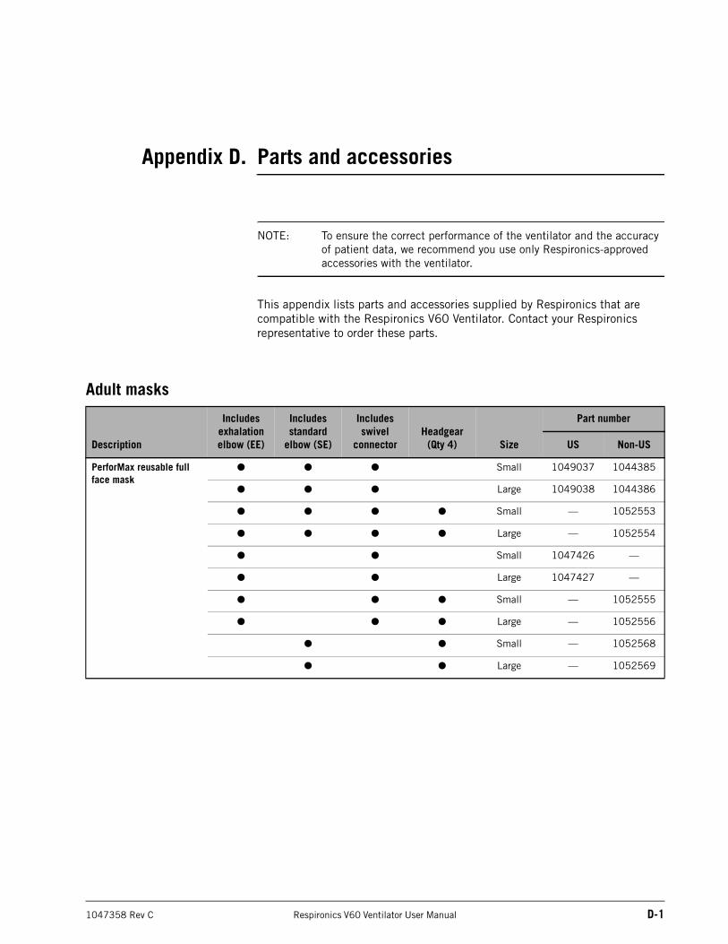
1047358 Rev C Respironics V60 Ventilator User Manual D-1
Appendix D. Parts and accessories
NOTE: To ensure the correct performance of the ventilator and the accuracy of patient data, we recommend you use only Respironics-approved accessories with the ventilator.
This appendix lists parts and accessories supplied by Respironics that are compatible with the Respironics V60 Ventilator. Contact your Respironics representative to order these parts.
Adult masks
Description
Includes exhalation elbow (EE)
Includes standard
elbow (SE)
Includes swivel
connectorHeadgear
(Qty 4) Size
Part number
US Non-US
PerforMax reusable full face mask
● ● ● Small 1049037 1044385
● ● ● Large 1049038 1044386
● ● ● ● Small — 1052553
● ● ● ● Large — 1052554
● ● Small 1047426 —
● ● Large 1047427 —
● ● ● Small — 1052555
● ● ● Large — 1052556
● ● Small — 1052568
● ● Large — 1052569
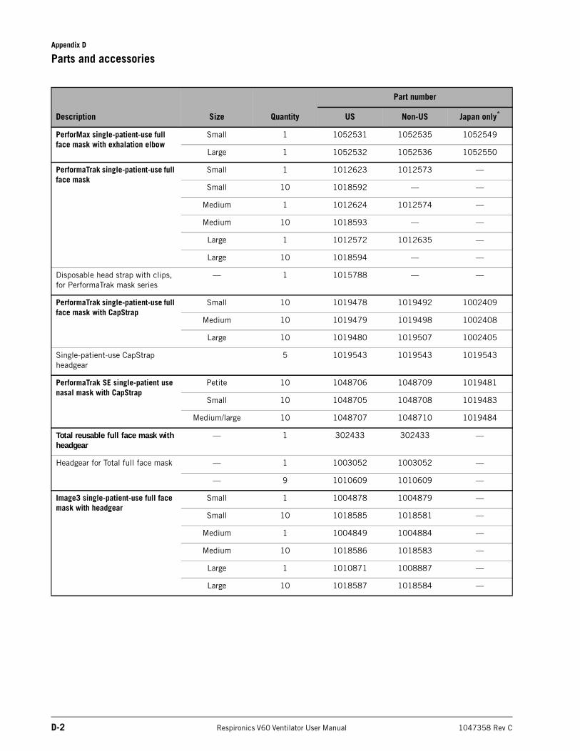
Appendix D
D-2 Respironics V60 Ventilator User Manual 1047358 Rev C
Parts and accessories
Description Size Quantity
Part number
US Non-US Japan only*
PerforMax single-patient-use full face mask with exhalation elbow
Small 1 1052531 1052535 1052549
Large 1 1052532 1052536 1052550
PerformaTrak single-patient-use full face mask
Small 1 1012623 1012573 —
Small 10 1018592 — —
Medium 1 1012624 1012574 —
Medium 10 1018593 — —
Large 1 1012572 1012635 —
Large 10 1018594 — —
Disposable head strap with clips, for PerformaTrak mask series
— 1 1015788 — —
PerformaTrak single-patient-use full face mask with CapStrap
Small 10 1019478 1019492 1002409
Medium 10 1019479 1019498 1002408
Large 10 1019480 1019507 1002405
Single-patient-use CapStrap headgear
5 1019543 1019543 1019543
PerformaTrak SE single-patient use nasal mask with CapStrap
Petite 10 1048706 1048709 1019481
Small 10 1048705 1048708 1019483
Medium/large 10 1048707 1048710 1019484
Total reusable full face mask with headgear
— 1 302433 302433 —
Headgear for Total full face mask — 1 1003052 1003052 —
— 9 1010609 1010609 —
Image3 single-patient-use full face mask with headgear
Small 1 1004878 1004879 —
Small 10 1018585 1018581 —
Medium 1 1004849 1004884 —
Medium 10 1018586 1018583 —
Large 1 1010871 1008887 —
Large 10 1018587 1018584 —
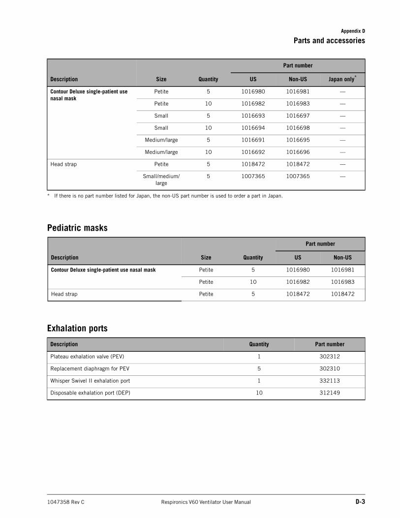
Appendix D
Parts and accessories
1047358 Rev C Respironics V60 Ventilator User Manual D-3
Pediatric masks
Exhalation ports
Contour Deluxe single-patient use nasal mask
Petite 5 1016980 1016981 —
Petite 10 1016982 1016983 —
Small 5 1016693 1016697 —
Small 10 1016694 1016698 —
Medium/large 5 1016691 1016695 —
Medium/large 10 1016692 1016696 —
Head strap Petite 5 1018472 1018472 —
Small/medium/large
5 1007365 1007365 —
* If there is no part number listed for Japan, the non-US part number is used to order a part in Japan.
Description Size Quantity
Part number
US Non-US Japan only*
Description Size Quantity
Part number
US Non-US
Contour Deluxe single-patient use nasal mask Petite 5 1016980 1016981
Petite 10 1016982 1016983
Head strap Petite 5 1018472 1018472
Description Quantity Part number
Plateau exhalation valve (PEV) 1 302312
Replacement diaphragm for PEV 5 302310
Whisper Swivel II exhalation port 1 332113
Disposable exhalation port (DEP) 10 312149
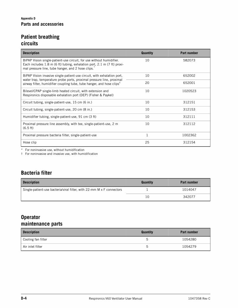
Appendix D
D-4 Respironics V60 Ventilator User Manual 1047358 Rev C
Parts and accessories
Patient breathing circuits
Bacteria filter
Operator maintenance parts
Description Quantity Part number
BiPAP Vision single-patient-use circuit, for use without humidifier. Each includes 1.8 m (6 ft) tubing, exhalation port, 2.1 m (7 ft) proxi-mal pressure line, tube hanger, and 2 hose clips.*
* For noninvasive use, without humidification
10 582073
BiPAP Vision invasive single-patient-use circuit, with exhalation port, water trap, temperature probe ports, proximal pressure line, proximal airway filter, humidifier coupling tube, tube hanger, and hose clips†
† For noninvasive and invasive use, with humidification
10 652002
20 652001
Bilevel/CPAP single-limb heated circuit, with extension andRespironics disposable exhalation port (DEP) (Fisher & Paykel)
10 1020523
Circuit tubing, single-patient-use, 15 cm (6 in.) 10 312151
Circuit tubing, single-patient-use, 20 cm (8 in.) 10 312153
Humidifier tubing, single-patient-use, 91 cm (3 ft) 10 312111
Proximal pressure line assembly, with tee, single-patient-use, 2 m (6.5 ft)
10 312112
Proximal pressure bacteria filter, single-patient-use 1 1002362
Hose clip 25 312154
Description Quantity Part number
Single-patient-use bacteria/viral filter, with 22-mm M x F connectors 1 1014047
10 342077
Description Quantity Part number
Cooling fan filter 5 1054280
Air inlet filter 5 1054279
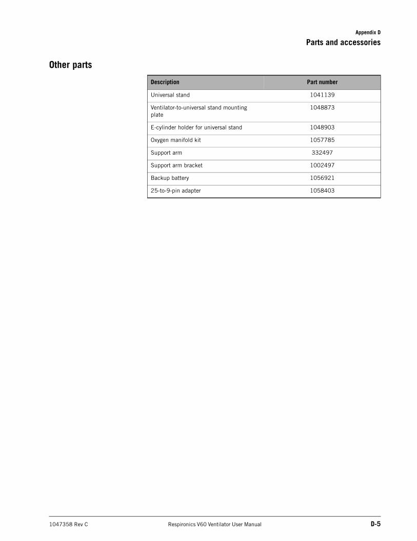
Appendix D
Parts and accessories
1047358 Rev C Respironics V60 Ventilator User Manual D-5
Other parts
Description Part number
Universal stand 1041139
Ventilator-to-universal stand mounting plate
1048873
E-cylinder holder for universal stand 1048903
Oxygen manifold kit 1057785
Support arm 332497
Support arm bracket 1002497
Backup battery 1056921
25-to-9-pin adapter 1058403

Appendix D
D-6 Respironics V60 Ventilator User Manual 1047358 Rev C
Parts and accessories
(This page is intentionally blank.)
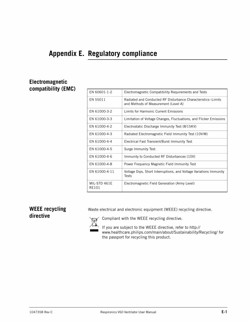
1047358 Rev C Respironics V60 Ventilator User Manual E-1
Appendix E. Regulatory compliance
Electromagnetic compatibility (EMC)
WEEE recycling directive
Waste electrical and electronic equipment (WEEE) recycling directive.
Compliant with the WEEE recycling directive.
If you are subject to the WEEE directive, refer to http://www.healthcare.philips.com/main/about/Sustainability/Recycling/ for the passport for recycling this product.
EN 60601-1-2 Electromagnetic Compatibility Requirements and Tests
EN 55011 Radiated and Conducted RF Disturbance Characteristics--Limits and Methods of Measurement (Level A)
EN 61000-3-2 Limits for Harmonic Current Emissions
EN 61000-3-3 Limitation of Voltage Changes, Fluctuations, and Flicker Emissions
EN 61000-4-2 Electrostatic Discharge Immunity Test (8/15KV)
EN 61000-4-3 Radiated Electromagnetic Field Immunity Test (10V/M)
EN 61000-4-4 Electrical Fast Transient/Burst Immunity Test
EN 61000-4-5 Surge Immunity Test
EN 61000-4-6 Immunity to Conducted RF Disturbances (10V)
EN 61000-4-8 Power Frequency Magnetic Field Immunity Test
EN 61000-4-11 Voltage Dips, Short Interruptions, and Voltage Variations Immunity Tests
MIL-STD 461E RE101
Electromagnetic Field Generation (Army Level)
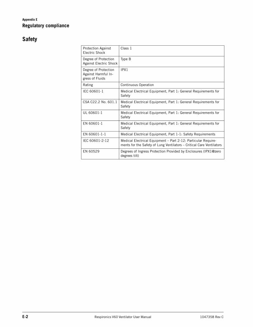
Appendix E
E-2 Respironics V60 Ventilator User Manual 1047358 Rev C
Regulatory compliance
SafetyProtection Against Electric Shock
Class 1
Degree of Protection Against Electric Shock
Type B
Degree of Protection Against Harmful In-gress of Fluids
IPX1
Rating Continuous Operation
IEC 60601-1 Medical Electrical Equipment, Part 1: General Requirements for Safety
CSA C22.2 No. 601.1 Medical Electrical Equipment, Part 1: General Requirements for Safety
UL 60601-1 Medical Electrical Equipment, Part 1: General Requirements for Safety
EN 60601-1 Medical Electrical Equipment, Part 1: General Requirements for Safety
EN 60601-1-1 Medical Electrical Equipment, Part 1-1: Safety Requirements
IEC 60601-2-12 Medical Electrical Equipment – Part 2-12: Particular Require-ments for the Safety of Lung Ventilators – Critical Care Ventilators
EN 60529 Degrees of Ingress Protection Provided by Enclosures (IPX1@zero degrees tilt)
1047358 Rev C Respironics V60 Ventilator User Manual F-1
Appendix F. Diagnostic mode
In the diagnostic mode you select the language of software display, set the date and time, select pressure units, enable software options, and calibrate the touchscreen.
NOTE: The diagnostic mode is primarily for use by Respironics-authorized service personnel to download software and perform other diagnostic procedures.
Entering the diagnostic mode
WARNING: To prevent possible patient injury, do not enter the diagnostic mode while a patient is connected to the ventilator. Verify that the patient is disconnected before proceeding.
Enter the diagnostic mode as follows:
1. Make sure the patient is disconnected and the ventilator is powered off.
2. Press and hold the Accept button on the navigation ring and turn on the ventilator by pressing the ON/Shutdown key. The screen displays Press again for Diagnostics or wait for Ventilation.
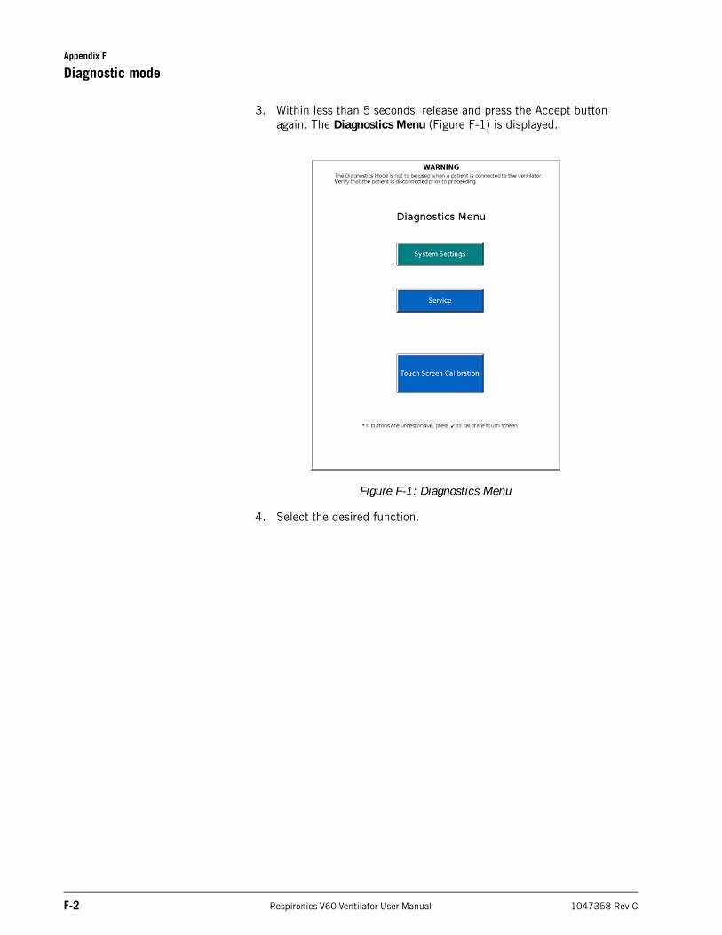
Appendix F
F-2 Respironics V60 Ventilator User Manual 1047358 Rev C
Diagnostic mode
3. Within less than 5 seconds, release and press the Accept button again. The Diagnostics Menu (Figure F-1) is displayed.
Figure F-1: Diagnostics Menu
4. Select the desired function.
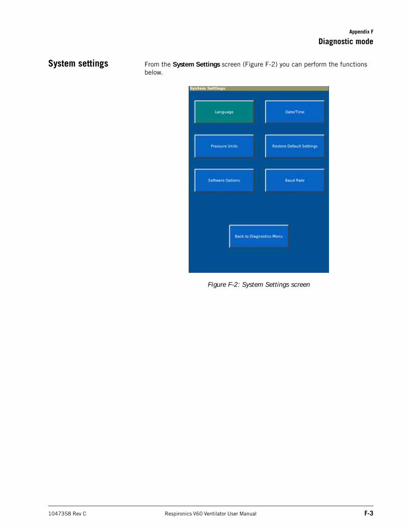
Appendix F
Diagnostic mode
1047358 Rev C Respironics V60 Ventilator User Manual F-3
System settings From the System Settings screen (Figure F-2) you can perform the functions below.
Figure F-2: System Settings screen
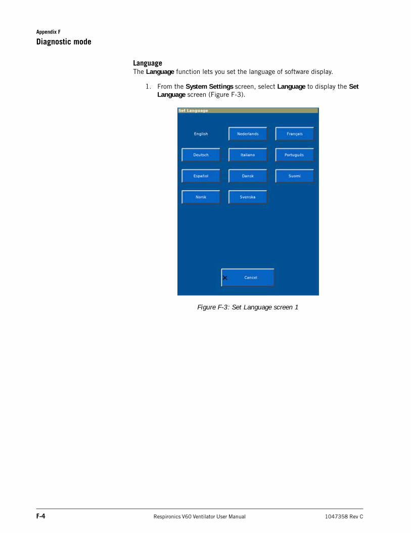
Appendix F
F-4 Respironics V60 Ventilator User Manual 1047358 Rev C
Diagnostic mode
LanguageThe Language function lets you set the language of software display.
1. From the System Settings screen, select Language to display the Set Language screen (Figure F-3).
Figure F-3: Set Language screen 1
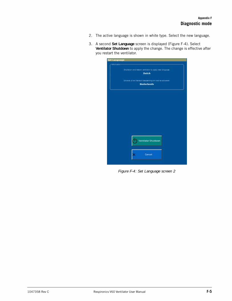
Appendix F
Diagnostic mode
1047358 Rev C Respironics V60 Ventilator User Manual F-5
2. The active language is shown in white type. Select the new language.
3. A second Set Language screen is displayed (Figure F-4). Select Ventilator Shutdown to apply the change. The change is effective after you restart the ventilator.
Figure F-4: Set Language screen 2
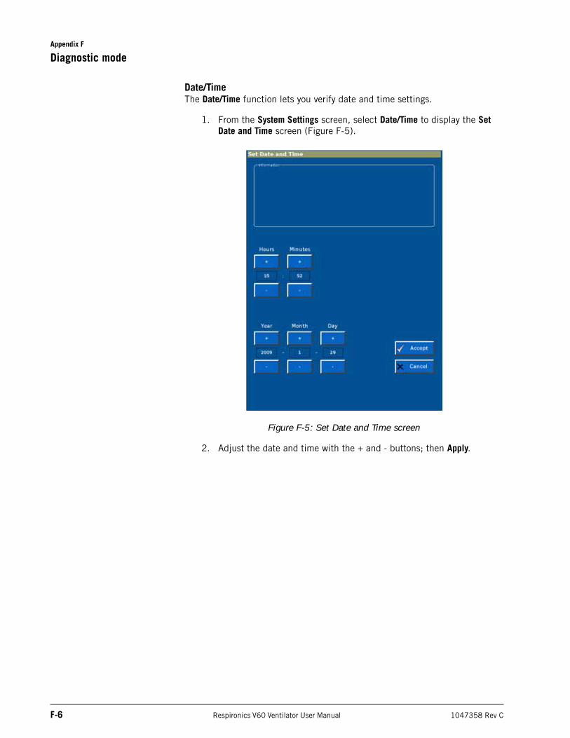
Appendix F
F-6 Respironics V60 Ventilator User Manual 1047358 Rev C
Diagnostic mode
Date/TimeThe Date/Time function lets you verify date and time settings.
1. From the System Settings screen, select Date/Time to display the Set Date and Time screen (Figure F-5).
Figure F-5: Set Date and Time screen
2. Adjust the date and time with the + and - buttons; then Apply.
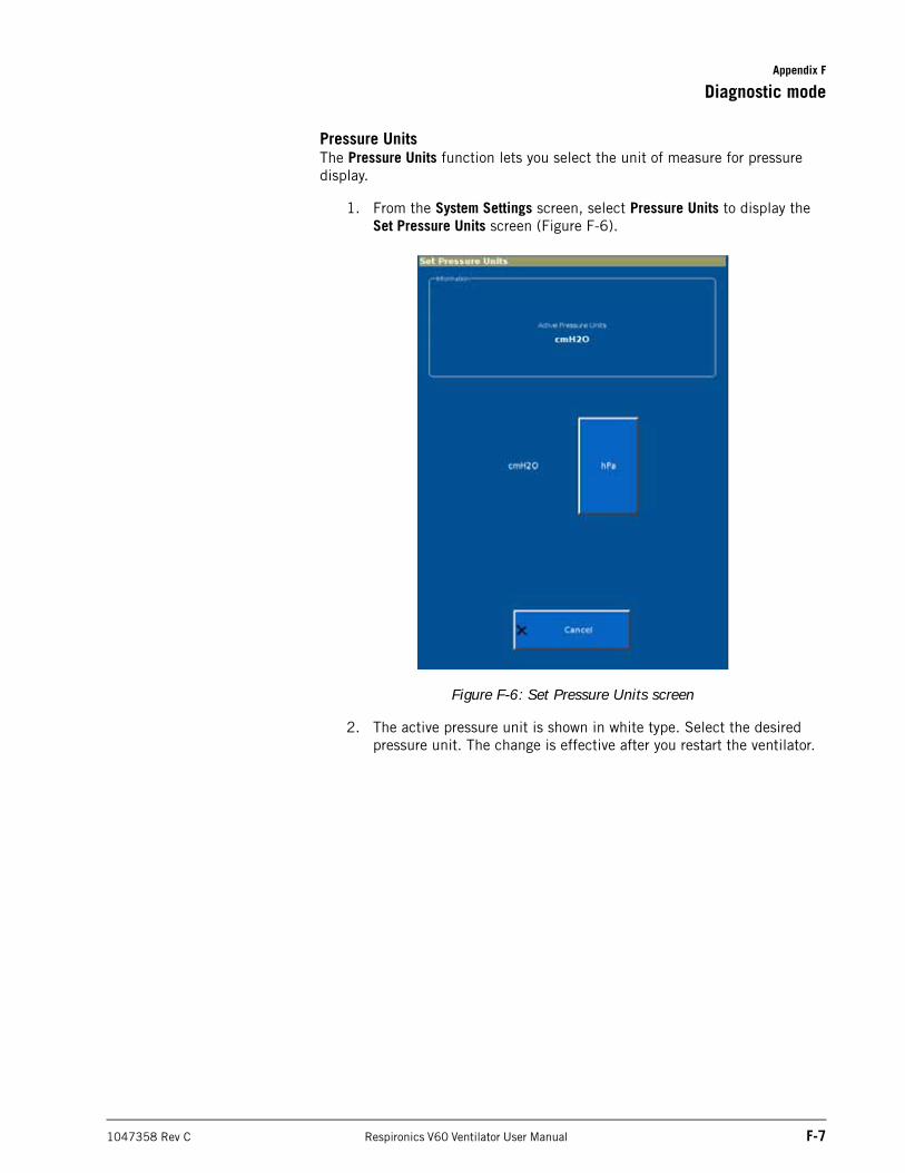
Appendix F
Diagnostic mode
1047358 Rev C Respironics V60 Ventilator User Manual F-7
Pressure UnitsThe Pressure Units function lets you select the unit of measure for pressure display.
1. From the System Settings screen, select Pressure Units to display the Set Pressure Units screen (Figure F-6).
Figure F-6: Set Pressure Units screen
2. The active pressure unit is shown in white type. Select the desired pressure unit. The change is effective after you restart the ventilator.
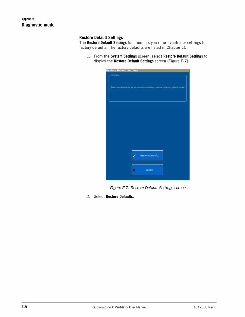
Appendix F
F-8 Respironics V60 Ventilator User Manual 1047358 Rev C
Diagnostic mode
Restore Default SettingsThe Restore Default Settings function lets you return ventilator settings to factory defaults. The factory defaults are listed in Chapter 10.
1. From the System Settings screen, select Restore Default Settings to display the Restore Default Settings screen (Figure F-7).
Figure F-7: Restore Default Settings screen
2. Select Restore Defaults.
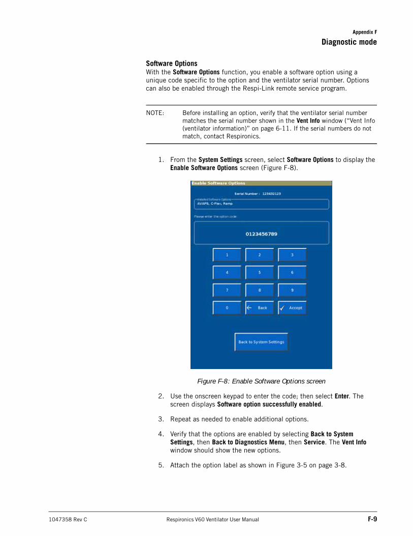
Appendix F
Diagnostic mode
1047358 Rev C Respironics V60 Ventilator User Manual F-9
Software OptionsWith the Software Options function, you enable a software option using a unique code specific to the option and the ventilator serial number. Options can also be enabled through the Respi-Link remote service program.
NOTE: Before installing an option, verify that the ventilator serial number matches the serial number shown in the Vent Info window (“Vent Info (ventilator information)” on page 6-11. If the serial numbers do not match, contact Respironics.
1. From the System Settings screen, select Software Options to display the Enable Software Options screen (Figure F-8).
Figure F-8: Enable Software Options screen
2. Use the onscreen keypad to enter the code; then select Enter. The screen displays Software option successfully enabled.
3. Repeat as needed to enable additional options.
4. Verify that the options are enabled by selecting Back to System Settings, then Back to Diagnostics Menu, then Service. The Vent Info window should show the new options.
5. Attach the option label as shown in Figure 3-5 on page 3-8.
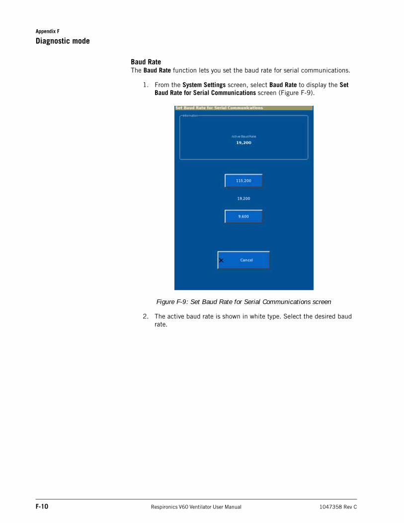
Appendix F
F-10 Respironics V60 Ventilator User Manual 1047358 Rev C
Diagnostic mode
Baud RateThe Baud Rate function lets you set the baud rate for serial communications.
1. From the System Settings screen, select Baud Rate to display the Set Baud Rate for Serial Communications screen (Figure F-9).
Figure F-9: Set Baud Rate for Serial Communications screen
2. The active baud rate is shown in white type. Select the desired baud rate.
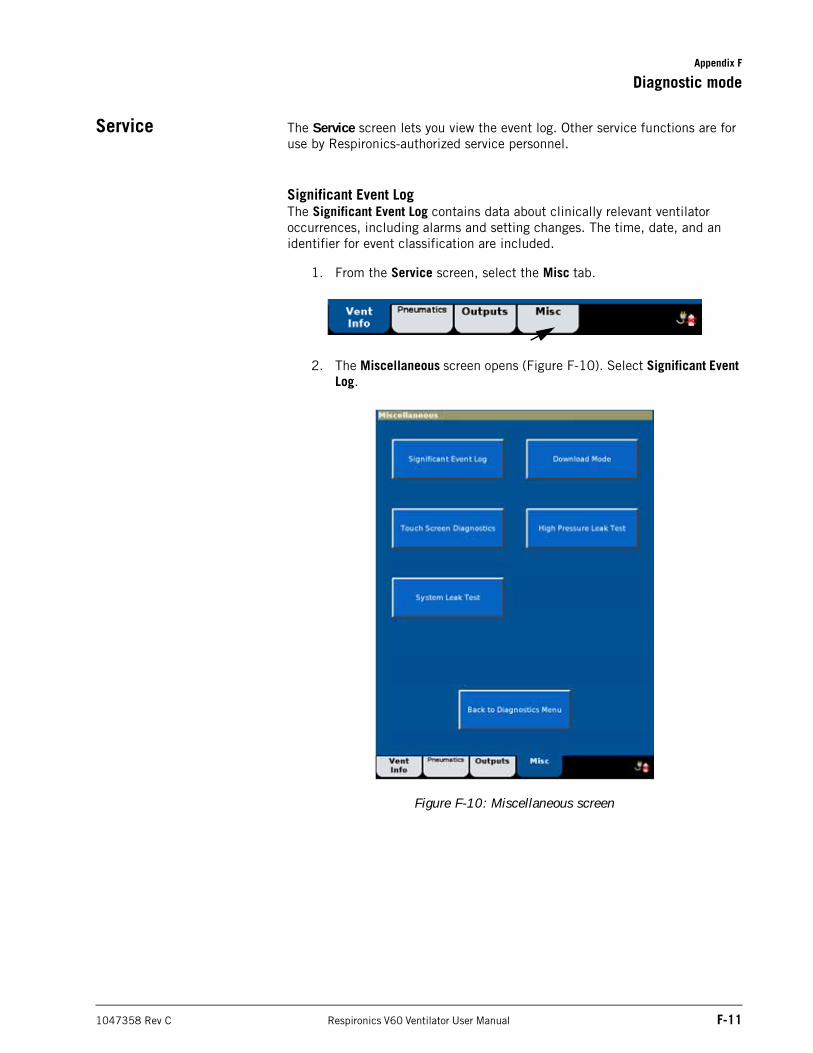
Appendix F
Diagnostic mode
1047358 Rev C Respironics V60 Ventilator User Manual F-11
Service The Service screen lets you view the event log. Other service functions are for use by Respironics-authorized service personnel.
Significant Event LogThe Significant Event Log contains data about clinically relevant ventilator occurrences, including alarms and setting changes. The time, date, and an identifier for event classification are included.
1. From the Service screen, select the Misc tab.
2. The Miscellaneous screen opens (Figure F-10). Select Significant Event Log.
Figure F-10: Miscellaneous screen
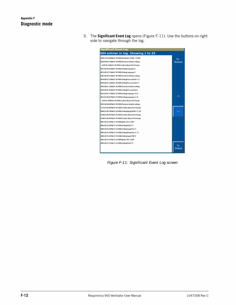
Appendix F
F-12 Respironics V60 Ventilator User Manual 1047358 Rev C
Diagnostic mode
3. The Significant Event Log opens (Figure F-11). Use the buttons on right side to navigate through the log.
Figure F-11: Significant Event Log screen
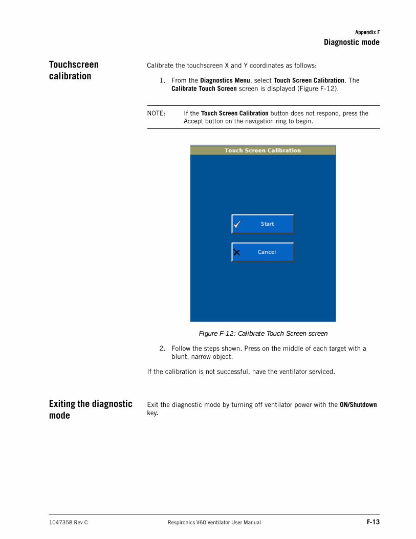
Appendix F
Diagnostic mode
1047358 Rev C Respironics V60 Ventilator User Manual F-13
Touchscreen calibration
Calibrate the touchscreen X and Y coordinates as follows:
1. From the Diagnostics Menu, select Touch Screen Calibration. The Calibrate Touch Screen screen is displayed (Figure F-12).
NOTE: If the Touch Screen Calibration button does not respond, press the Accept button on the navigation ring to begin.
Figure F-12: Calibrate Touch Screen screen
2. Follow the steps shown. Press on the middle of each target with a blunt, narrow object.
If the calibration is not successful, have the ventilator serviced.
Exiting the diagnostic mode
Exit the diagnostic mode by turning off ventilator power with the ON/Shutdown key.

Appendix F
F-14 Respironics V60 Ventilator User Manual 1047358 Rev C
Diagnostic mode
(This page is intentionally blank.)
1047358 Rev C Respironics V60 Ventilator User Manual Glossary-1
Glossary
A Ampere, a unit of current.
AC Alternating current.
Alarm Silence button Silences alarm sound for 2 minutes.
Assisted breath Breath in which the patient begins inspiration, but the ventilator controls the inspiratory phase and ends inspiration.
Auto-Trak Sensitivity A Respironics innovation in triggering and cycling that utilizes several different methods to provide enhanced sensitivity in the presence of leaks and changing breathing patterns.
AVAPS Average volume-assured pressure support. A ventilation mode in which pressure support is automatically adjusted to maintain the user-defined target tidal volume.
AVAPS Maximum IPAP Pressure See Max P.
AVAPS Minimum IPAP Pressure See Min P.
AVAPS Target Tidal Volume See VT.
Average volume-assured pressure support See AVAPS.
Baseline As in baseline pressure. The pressure at end exhalation.
BPM Breaths per minute.
BTPS Body temperature (98 °F, ambient pressure), 100% saturated (with water vapor).
C-Flex A setting in CPAP mode, which enhances traditional CPAP by reducing the pressure at the start of exhalation.
cmH2O Centimeters of water, a unit of pressure measurement.
Continuous positive airway pressure See CPAP.
CPAP Continuous positive airway pressure. A ventilation mode that provides a single, continuous level of positive pressure to the patient and a control setting in that mode.
Cycle To end inspiration.
Glossary-2 Respironics V60 Ventilator User Manual 1047358 Rev C
Glossary
dB(A) Decibel, a unit of acoustic power.
DISS Diameter index safety standard, a standard for high-pressure gas inlet fittings.
EPAP Expiratory positive airway pressure. A control setting. The application and maintenance of pressure above atmospheric at the airway throughout the exhalation phase of positive-pressure mechanical ventilation.
Estimated exhaled tidal volume See VT.
Estimated minute ventilation See E.
Estimated patient leak See Pt. Leak
Estimated total leak See Tot.Leak.
ET Endotracheal.
Exhalation Port test Performed to assess the leak flow rate through the exhalation port.
Expiratory positive airway pressure See EPAP.
HIP High Inspiratory Pressure Alarm, an alarm setting.
Hi Rate High Rate Alarm, an alarm setting.
Hi VT High Tidal Volume Alarm, an alarm setting.
hPa Hectopascal, a unit of pressure measurement. 1 hPa is equal to 1 mbar, which is approximately equal to 1 cmH2O.
ID Inner diameter.
IEC International Electrotechnical Commission.
I:E ratio Ratio of inspiratory to expiratory time.
Inop Inoperative.
Inspiration:exhalation ratio See I:E ratio.
Inspiratory positive airway pressure See IPAP.
Inspiratory time See I-Time.
Inspiratory duty cycle See TI/TTOT.
Intentional leakage “Known,” quantifiable leakage that is a function of the mask.
V•
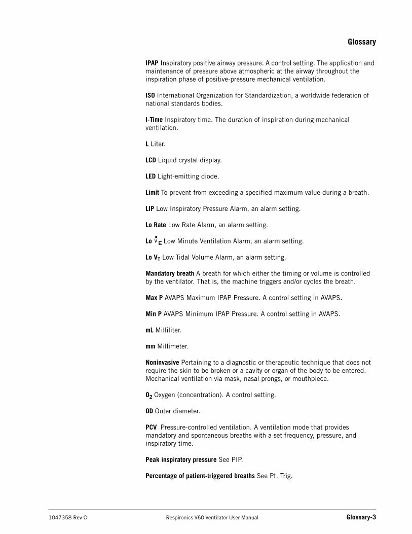
Glossary
1047358 Rev C Respironics V60 Ventilator User Manual Glossary-3
IPAP Inspiratory positive airway pressure. A control setting. The application and maintenance of pressure above atmospheric at the airway throughout the inspiration phase of positive-pressure mechanical ventilation.
ISO International Organization for Standardization, a worldwide federation of national standards bodies.
I-Time Inspiratory time. The duration of inspiration during mechanical ventilation.
L Liter.
LCD Liquid crystal display.
LED Light-emitting diode.
Limit To prevent from exceeding a specified maximum value during a breath.
LIP Low Inspiratory Pressure Alarm, an alarm setting.
Lo Rate Low Rate Alarm, an alarm setting.
Lo E Low Minute Ventilation Alarm, an alarm setting.
Lo VT Low Tidal Volume Alarm, an alarm setting.
Mandatory breath A breath for which either the timing or volume is controlled by the ventilator. That is, the machine triggers and/or cycles the breath.
Max P AVAPS Maximum IPAP Pressure. A control setting in AVAPS.
Min P AVAPS Minimum IPAP Pressure. A control setting in AVAPS.
mL Milliliter.
mm Millimeter.
Noninvasive Pertaining to a diagnostic or therapeutic technique that does not require the skin to be broken or a cavity or organ of the body to be entered. Mechanical ventilation via mask, nasal prongs, or mouthpiece.
O2 Oxygen (concentration). A control setting.
OD Outer diameter.
PCV Pressure-controlled ventilation. A ventilation mode that provides mandatory and spontaneous breaths with a set frequency, pressure, and inspiratory time.
Peak inspiratory pressure See PIP.
Percentage of patient-triggered breaths See Pt. Trig.
V•
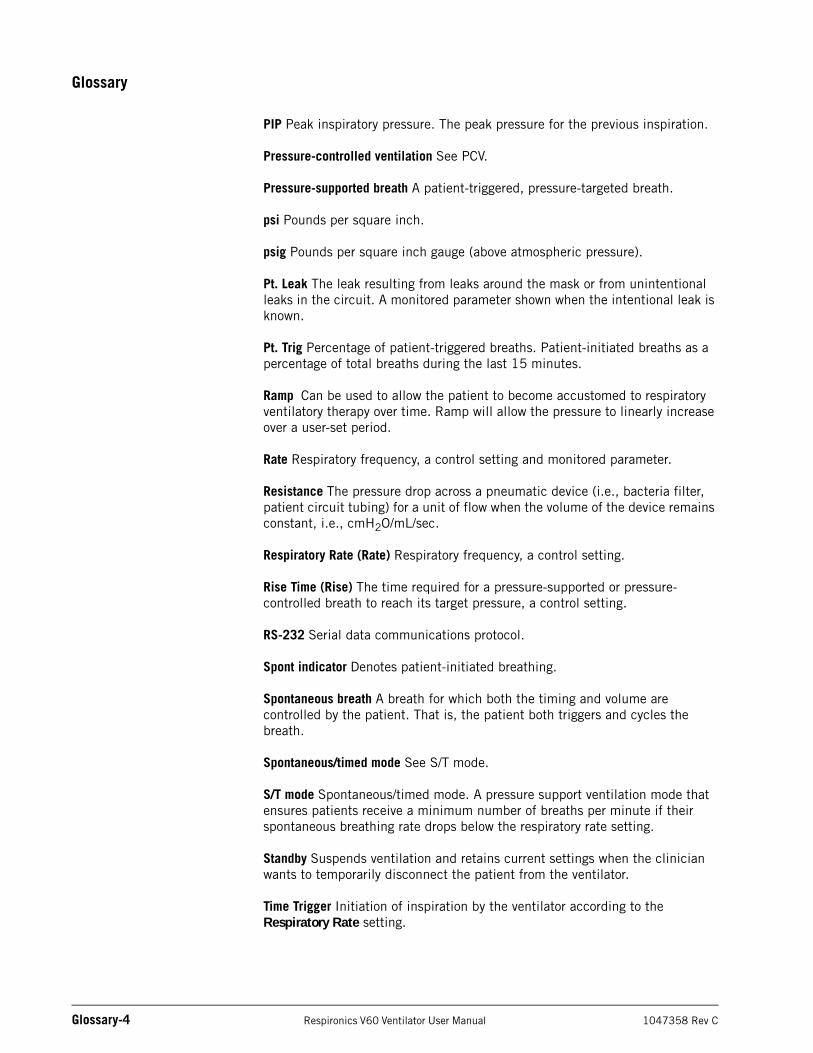
Glossary-4 Respironics V60 Ventilator User Manual 1047358 Rev C
Glossary
PIP Peak inspiratory pressure. The peak pressure for the previous inspiration.
Pressure-controlled ventilation See PCV.
Pressure-supported breath A patient-triggered, pressure-targeted breath.
psi Pounds per square inch.
psig Pounds per square inch gauge (above atmospheric pressure).
Pt. Leak The leak resulting from leaks around the mask or from unintentional leaks in the circuit. A monitored parameter shown when the intentional leak is known.
Pt. Trig Percentage of patient-triggered breaths. Patient-initiated breaths as a percentage of total breaths during the last 15 minutes.
Ramp Can be used to allow the patient to become accustomed to respiratory ventilatory therapy over time. Ramp will allow the pressure to linearly increase over a user-set period.
Rate Respiratory frequency, a control setting and monitored parameter.
Resistance The pressure drop across a pneumatic device (i.e., bacteria filter, patient circuit tubing) for a unit of flow when the volume of the device remains constant, i.e., cmH2O/mL/sec.
Respiratory Rate (Rate) Respiratory frequency, a control setting.
Rise Time (Rise) The time required for a pressure-supported or pressure-controlled breath to reach its target pressure, a control setting.
RS-232 Serial data communications protocol.
Spont indicator Denotes patient-initiated breathing.
Spontaneous breath A breath for which both the timing and volume are controlled by the patient. That is, the patient both triggers and cycles the breath.
Spontaneous/timed mode See S/T mode.
S/T mode Spontaneous/timed mode. A pressure support ventilation mode that ensures patients receive a minimum number of breaths per minute if their spontaneous breathing rate drops below the respiratory rate setting.
Standby Suspends ventilation and retains current settings when the clinician wants to temporarily disconnect the patient from the ventilator.
Time Trigger Initiation of inspiration by the ventilator according to the Respiratory Rate setting.
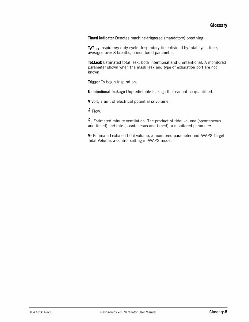
Glossary
1047358 Rev C Respironics V60 Ventilator User Manual Glossary-5
Timed indicator Denotes machine-triggered (mandatory) breathing.
TI/TTOT Inspiratory duty cycle. Inspiratory time divided by total cycle time, averaged over 8 breaths, a monitored parameter.
Tot.Leak Estimated total leak, both intentional and unintentional. A monitored parameter shown when the mask leak and type of exhalation port are not known.
Trigger To begin inspiration.
Unintentional leakage Unpredictable leakage that cannot be quantified.
V Volt, a unit of electrical potential or volume.
Flow.
E Estimated minute ventilation. The product of tidal volume (spontaneous and timed) and rate (spontaneous and timed), a monitored parameter.
VT Estimated exhaled tidal volume, a monitored parameter and AVAPS Target Tidal Volume, a control setting in AVAPS mode.
V•
V•

Glossary-6 Respironics V60 Ventilator User Manual 1047358 Rev C
Glossary
(This page is intentionally blank.)
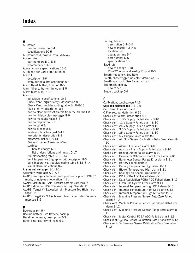
1047358 Rev C Respironics V60 Ventilator User Manual Index-1
AAC power
how to connect to 5-4specifications 10-5
AC power cord, how to install A-6–A-7Accessories
part numbers D-1–D-5recommended 3-5
Acoustic noise specifications 10-6Air inlet filter. See Filter, air inletAlarm LED
description 3-6state during alarm conditions 8-3
Alarm Reset button, function 8-5Alarm Silence button, function 8-5Alarm tests 5-10–5-11Alarms
adjustable, specifications 10-3Check Vent (high-priority), description 8-3Check Vent, troubleshooting table 8-10–8-13high-priority, description 8-3how to clear autoreset alarms from the Alarms list 8-5how to hide/display messages 8-6how to manually reset 8-5how to respond to 8-1how to set 6-6how to silence 8-5loudness, how to adjust 6-11low-priority, description 8-3messages, list 8-6–8-14See also name of specific alarmsettings
how to change 6-6list of descriptions and ranges 6-17
troubleshooting table 8-6–8-14Vent Inoperative (high-priority), description 8-3Vent Inoperative, troubleshooting table 8-13–8-14visual alarm indications 8-2
Alarms and messages 8-1–8-14Assembly, ventilator A-2–A-7AVAPS (average volume-assured pressure support (AVAPS)
mode, principles of operation 4-11AVAPS Maximum IPAP Pressure setting. See Max PAVAPS Minimum IPAP Pressure setting. See Min PAVAPS: Target VT Exceeded. Min Pressure Too High mes-
sage 8-6AVAPS: Target VT Not Achieved. Insufficient Max Pressure
message 8-6
BBackup alarm 5-4Backup battery. See Battery, backupBaseline pressure, description 4-3Batch settings, how to make 6-3
Battery, backupdescription 5-4–5-5how to install A-3–A-5location 3-8operation time 5-4part number D-5specifications 10-5
Baud ratehow to change F-10RS-232 serial and analog I/O port B-3
Breath frequency. See RateBreath phase/trigger indicator, definition 7-2Breathing circuit. See Patient circuitBrightness, display
how to set 6-11Buzzer, backup 5-4
CCalibration, touchscreen F-13Care and maintenance 9-1–9-6Cart. See Universal standC-Flex setting, definition 6-15Check Vent alarm, description 8-3Check Vent: 1.8 V Supply Failed alarm 8-10Check Vent: 12 V Supply Failed alarm 8-10Check Vent: 24 V Supply Failed alarm 8-10Check Vent: 3.3 V Supply Failed alarm 8-10Check Vent: 35 V Supply Failed alarm 8-10Check Vent: 5 V Supply Failed alarm 8-10Check Vent: Air Flow Sensor Calibration Data Error alarm 8-
10Check Vent: Alarm LED Failed alarm 8-10Check Vent: Auxiliary Alarm Supply Failed alarm 8-10Check Vent: Backup Alarm Failed alarm 8-10Check Vent: Barometer Calibration Data Error alarm 8-10Check Vent: Barometer Sensor Range Error alarm 8-11Check Vent: Battery Failed alarm 8-11Check Vent: Battery Temperature High alarm 8-11Check Vent: Blower Temperature High alarm 8-11Check Vent: Cooling Fan Speed Error alarm 8-11Check Vent: CPU PCBA ADC Failed alarm 8-11Check Vent: Data Acquisition PCBA ADC Failed alarm 8-11Check Vent: Flash File System Error alarm 8-11Check Vent: Internal Temperature High CPU alarm 8-11Check Vent: Internal Temperature High Daq alarm 8-12Check Vent: Internal Temperature High Mtr alarm 8-12Check Vent: Machine Pressure Sensor Auto-Zero Failed
alarm 8-12Check Vent: Machine Pressure Sensor Calibration Data Error
alarm 8-12Check Vent: Machine Pressure Sensor Range Error alarm 8-
12Check Vent: Motor Control PCBA ADC Failed alarm 8-12Check Vent: O2 Flow Sensor Calibration Data Error alarm 8-12Check Vent: O2 Pressure Sensor Calibration Data Error alarm
8-12
Index
Index
Index-2 Respironics V60 Ventilator User Manual 1047358 Rev C
Check Vent: O2 Supply Pressure Sensor Range Error alarm 8-12
Check Vent: OVP Circuit Failed alarm 8-12Check Vent: Oxygen Device Failed alarm 8-12Check Vent: Primary Alarm Failed alarm 8-12Check Vent: Program CRC Test Failed alarm 8-12Check Vent: Proximal Pressure Sensor Auto-Zero Failed
alarm 8-13Check Vent: Proximal Pressure Sensor Calibration Data Error
alarm 8-13Check Vent: Proximal Pressure Sensor Range Error alarm 8-
13Circuit, patient. See Patient circuitCleaning
touchscreen 9-2ventilator exterior 9-1
CO2 rebreathing precaution 3-1Communications interface B-1–B-12Connector
oxygen inlethow to install A-6location 3-8
remote alarm/nurse call, location 3-8RS-232 serial and analog I/O, location 3-8
Continuous positive airway pressure. See CPAPContinuous-tone alarm 5-4Contour Deluxe masks. See MasksContraindications 3-2Control settings
how to change 6-3–6-4how to make batch setting changes 6-3list of descriptions and ranges 6-15–6-16ranges, resolutions, and accuracies 10-1See also name of specific setting
Cooling fan filter. See Filter, cooling fanCPAP (continuous positive airway pressure) mode 4-8CPAP (continuous positive airway pressure) setting, defini-
tion 6-15
DDate and time, how to change F-6Decontamination 9-1–9-2Default factory settings, how to restore F-8Definitions G-1–G-5Delivered pressure specifications 10-6Diagnostic mode F-1–F-13
how to calibrate touchscreen F-13how to change baud rate F-10how to change date and time F-6how to change language F-4–F-5how to change pressure unit F-7how to enable software options F-9how to enter F-1how to exit F-13how to restore default factory settings F-8how to view event log F-11–F-12
Dimensions, ventilator 10-4Display, brightness, how to set 6-11
EElectrical specifications 10-5Electromagnetic compatibility (EMC), compliance with stan-
dards E-1Environmental specifications 10-5EPAP (expiratory positive airway pressure) setting, definition
6-15Estimated exhaled tidal volume. See VTEstimated minute ventilation. See VEEstimated total leak. See Tot.LeakEvent log, how to view F-11–F-12Exhalation port
how to select 6-7–6-9part numbers D-3
Exhalation port test, how to run 6-10–6-11Exhale breath phase indicator, definition 7-2Expiratory positive airway pressure. See EPAP
FFan filter. See Filter, cooling fanFilter
air inlethow to install 9-4maintenance schedule 9-3
cooling fanhow to clean or replace 9-5location 3-8maintenance schedule 9-3part number D-4
main flow (inspiratory) bacteriapart numbers D-4
main flow (inspiratory) bacteria, part numbers D-4First-time installation A-1–A-7Fitting. See ConnectorFrequency, breath. See Rate
GGeneral information 3-1–3-9Glossary G-1–G-5Graphical user interface
how to calibrate F-13illustration 3-9
GUI. See Graphical user interface
HHelp feature, description 6-14Hi Rate (High Rate Alarm) setting, definition 6-17Hi VT (High Tidal Volume Alarm) setting, definition 6-17High Inspiratory Pressure alarm 8-6High O2 Supply Pressure alarm 8-6High Rate alarm 8-7High Tidal Volume alarm 8-7High-priority alarm, description 8-3HIP (High Inspiratory Pressure Alarm) setting, definition 6-
17
Index
1047358 Rev C Respironics V60 Ventilator User Manual Index-3
IImage3 masks. See MasksInformational message, description 8-3Inlet filter. See Filter, air inletInspiration, triggering, volume method 4-3Inspiratory duty cycle. See TI/TTOTInspiratory positive airway pressure. See IPAPInspiratory time setting. See I-TimeInstallation
AC power cord A-7air inlet filter 9-4cooling fan filter 9-5oxygen inlet connector A-6
Intake filter. See Filter, air inletIntended use, Respironics V60 Ventilator 3-1Interface. See Patient interface or Communications inter-
faceIPAP (inspiratory positive airway pressure) setting, definition
6-15I-Time (inspiratory time) setting, definition 6-15
LLanguage, how to change F-4–F-5Leak adaptation, principles of operation 4-5–4-6Leak, estimated total. See Tot.LeakLIP (Low Inspiratory Pressure Alarm) setting, definition 6-17LIP T (Low Inspiratory Pressure Delay Time) setting, defini-
tion 6-17Lo Rate (Low Rate Alarm) setting, definition 6-17Lo VE (Low Minute Ventilation Alarm) setting, definition 6-
17Lo VT (Low Tidal Volume Alarm) setting, definition 6-17Locking and unlocking the screen 6-12Log, event, how to view F-11–F-12Loudness, how to set alarm 6-11Low Inspiratory Pressure alarm 8-7Low Inspiratory Pressure Alarm setting. See LIPLow Inspiratory Pressure Delay Time setting. See LIP TLow Internal Battery alarm 8-7Low Leak--CO2 Rebreathing Risk alarm 8-7Low Minute Ventilation alarm 8-7Low Minute Ventilation Alarm setting. See Lo VELow O2 Supply Pressure alarm 8-7Low Rate alarm 8-8Low Tidal Volume alarm 8-8Low-priority alarm, description 8-3
MMain flow bacteria filter. See Filter, main flow bacteriaMains power
how to connect to 5-4specifications 10-5
Maintenance. See Care and maintenanceMask:x, Exh Port:y Use Menu to change message 8-8Masks, ordering information D-1–D-3Max P (AVAPS Maximum IPAP Pressure) setting, definition
6-16Menu window, functions 6-11–6-12Message, informational, description 8-3
Min P (AVAPS Minimum IPAP Pressure) setting, definition 6-16
Minute ventilation. See VEModes, ventilation. See Ventilation modesMonitored parameters
definitions 7-2ranges, resolutions, and accuracies 10-2
Mounting the ventilator A-2
NNurse call connector, location 3-8Nurse call port B-12
OO2 setting, definition 6-16Operation 6-1Operator replacement parts, part numbers D-4Options, software, how to enable F-9Oxygen inlet connector
how to installlocation 3-8
Oxygen Not Available alarm 8-8Oxygen, how to connect 5-1–5-2
PParts and accessories D-1–D-5Patient circuit
how to install 5-2–5-3part numbers D-4
Patient Circuit Occluded alarm 8-8Patient data
ranges, resolutions, and accuracies 10-2See also Monitored parameters
Patient Disconnect alarm 8-9Patient interface
how to select for leak adjustment purposes 6-7–6-9See Masks
Patient leak. See Pt. Leak 7-2Patient monitoring 7-1–7-3Patient-triggered breaths. See Pt. TrigPCV (pressure-controlled ventilation) mode, principles of op-
eration 4-9Peak inspiratory pressure. See PIPPerformaTrak masks. See MasksPerforMax masks. See MasksPEV (plateau exhalation valve), part number D-3PIP (peak inspiratory pressure) monitored parameter, defini-
tion 7-2Plateau exhalation valve (PEV), part number D-3PM. See Preventive maintenancePort
exhalationhow to select 6-7–6-9how to test 6-10–6-11part numbers D-3
See also RS-232 serial and analog I/O port, Remote alarm port, or Connector
Index
Index-4 Respironics V60 Ventilator User Manual 1047358 Rev C
Power cordhow to install A-7location 3-8
Power cord retainer, location 3-8Power has been restored message 8-9Power indicators, illustration 5-5Preoperational check 5-8–5-9
required materials 5-8Preparing for ventilation 5-1–5-9Pressure Regulation High alarm 8-9Pressure unit, how to change F-7Pressure, baseline, description 4-3Pressure-controlled ventilation mode. See PCVPreventive maintenance 9-3–9-6
schedule 9-3Principles of operation 4-1–4-12Proximal Pressure Line Disconnect alarm 8-9Pt. Leak (patient leak) monitored parameter 7-2Pt. Trig (patient-triggered breaths) monitored parameter 7-2
RRamp Time setting, definition 6-16Rate (Respiratory Rate) setting, definition 6-16Rate monitored parameter, definition 7-2Regulatory compliance E-1–E-2Remote alarm cable kits B-12Remote alarm port B-12Remote alarm/nurse call connector, location 3-8Repacking and shipping 9-6Respi-Link remote diagnostic system
description 3-3location of Ethernet connector 3-8
Respiratory rate. See RateRespironics V60 Ventilator
front view 3-6physical description 3-4–3-8rear view 3-8side view 3-7system overview 3-2–3-3
Rise (Rise Time) setting, definition 6-16RS-232 serial and analog I/O port B-2–B-11
commands and transmission conventions B-3–B-11communications protocol B-3location B-1pinout of connector B-2SNDA record format B-8–B-11VRPT record format B-3–B-8
Running on Internal Battery alarm 8-9
SS/T (spontaneous/timed) mode, principles of operation 4-10Safety, compliance with standards E-1Scalars. See WaveformsScreen lock 6-12Send Variable-Length Ventilator Report. See SNDA com-
mandSend Ventilator Report command. See VRPT commandSettings, default factory, how to restore F-8Shutdown, ventilator 5-6
SNDA command B-8–B-11Software options, how to enable F-9Specifications. See Technical specificationsSpont (spontaneous) breath type indicator, definition 7-2Spontaneous/timed mode. See S/T modeStand. See Universal standStandby 6-12–6-13Start-up time specifications 10-6Symbols 2-9–2-14System Settings functions, in diagnostic mode F-3
TTechnical specifications 10-1–10-6
acoustic noise 10-6alarm settings 10-3control setting ranges, resolutions, and accuracies 10-1delivered pressure 10-6dimensions 10-4electrical 10-5environmental 10-5monitored parameter ranges, resolutions, and accuracies
10-2patient data ranges, resolutions, and accuracies 10-2ventilator start-up time 10-6weight 10-4
Testsalarm tests 5-10–5-11exhalation port 6-10–6-11
TI/TTOT (duty cycle) monitored parameter, definition 7-2Tidal volume, estimated exhaled. See VTTime and date, how to change F-6Timed breath type indicator, definition 7-2Tot.Leak (estimated total leak) monitored parameter, defini-
tion 7-2Total leak. See Tot.LeakTotal masks. See MasksTouchscreen
how to calibrate F-13how to clean 9-2
Triggeringprinciples of operation 4-3volume method 4-3
Trolley. See Universal standTroubleshooting alarms 8-6–8-14
UUniversal stand, mounting the ventilator to A-2Unpacking and inspection A-1Using Default Settings message 8-9
VVent Info (Ventilator Information) window, description 6-11Vent Inoperative 1000 3.3 V Supply Failed alarm 8-13Vent Inoperative 1001 12 V Supply Failed alarm 8-13Vent Inoperative 1002 Blower Temperature Too High alarm
8-13Vent Inoperative 1003 Internal Temperature High alarm 8-13Vent Inoperative 1004 Internal Temperature High alarm 8-13Vent Inoperative 1005 Internal Temperature High alarm 8-13
Index
1047358 Rev C Respironics V60 Ventilator User Manual Index-5
Vent Inoperative 1006 Data Acquisition PCBA ADC Failed alarm 8-13
Vent Inoperative 1007 Machine and Proximal Pressure Sen-sors Failed alarm 8-14
Vent Inoperative 1008 Machine and Proximal Pressure Sen-sors Failed alarm 8-14
Vent Inoperative 1009 Pressure Regulation High alarm 8-14Vent Inoperative 100A Data Acquisition PCBA ADC Refer-
ence Failed alarm 8-14Vent Inoperative 100B Watchdog Test Failed alarm 8-14Vent Inoperative alarm, description 8-3Ventilation modes
how to change 6-2principles of operation 4-7–4-12
Ventilator breathing circuit. See Patient circuitVentilator settings. See Control settings or Alarm settingsVolume
AVAPS Target Tidal Volume. See VTestimated exhaled tidal. See VTwaveform. See Waveforms
VRPT command B-3–B-8VT (AVAPS Target Tidal Volume) setting, definition 6-16VT (estimated exhaled tidal volume) monitored parameter 7-2
WWarnings, cautions, and notes 1-1–1-7Warranty C-1Waveforms
description 7-2how to freeze and unfreeze 7-3how to scale axes 7-2
WEEErecycling directive, compliance statement E-1Weight, ventilator 10-4Whisper Swivel II exhalation port, part number D-3

Index
Index-6 Respironics V60 Ventilator User Manual 1047358 Rev C
(This page is intentionally blank.)

Philips Healthcare is part ofRoyal Philips Electronics
www.philips.com/[email protected]
Manufacturer’s addressRespironics California, Inc.2271 Cosmos CourtCarlsbad, CA 92011USA
European representative addressRespironics Deutschland GmbHGewerbestrasse 17D-82211 HerrschingGermany
Printed in USA1047358 Rev C
© 2009 Koninklijke Philips Electronics N.V. All rights are reserved. Reproduction or transmission in whole or in part, in any form or by any means, electronic,mechanical or otherwise, is prohibited without the prior written consent of the copyright owner.