Embed Size (px)
Citation preview
RESTRAINTS
C
D
E
SECTION SRCA
B
SRS AIRBAG CONTROL SYSTEM
F
G
I
J
K
L
M
RC
N
O
P
CONTENTS
S
BASIC INSPECTION .................................... 3
DIAGNOSIS AND REPAIR WORK FLOW ......... 3Work Flow .................................................................3
INTERMITTENTS INCIDENT .............................. 5Inspection Procedure ...............................................5Trouble Diagnosis with CONSULT-III .......................5
FUNCTION DIAGNOSIS ............................... 6
SRS AIR BAG SYSTEM ...................................... 6SRS Configuration ....................................................6SRS Component Parts Location ...............................6Driver Air Bag Module ...............................................7Front Passenger Air Bag Module ..............................7Front Side Air Bag .....................................................8Side Curtain Air Bag ..................................................8Front Seat Belt Pre-tensioner with Load Limiter .......8Direct-connect SRS Component Connectors ............8
OCCUPANT CLASSIFICATION SYSTEM .........10System Diagram ......................................................10Occupant Classification System (OCS) ..................10
PASSENGER SEAT BELT WARNING SYS-TEM ....................................................................11
System Diagram ......................................................11System Description .................................................11Component Parts Location ......................................11
ON BOARD DIAGNOSTIC (OBD) SYSTEM ......12Trouble Diagnosis Introduction ...............................12SRS Operation Check .............................................12Trouble Diagnosis without CONSULT-III ................14CONSULT-III Function (AIR BAG) ..........................14Self-Diagnosis Function (Without CONSULT-III) ....14
COMPONENT DIAGNOSIS .........................16
B1049 – B1052, B1054 – B1057 DRIVER AIR-BAG MODULE ...................................................16
Description ...............................................................16DTC Logic ................................................................16Diagnosis Procedure (Component diagnosis) .......17
B1065 – B1068, B1070 – B1073 PASSEN-GER AIRBAG MODULE ...................................19
Description ...............................................................19DTC Logic ................................................................19Diagnosis Procedure (Component diagnosis) .......20
B1134 – B1137 SIDE AIRBAG MODULE LH ...22Description ...............................................................22DTC Logic ................................................................22Diagnosis Procedure (Component diagnosis) .......23
B1129 – B1132 SIDE AIRBAG MODULE RH ...25Description ...............................................................25DTC Logic ................................................................25Diagnosis Procedure (Component diagnosis) .......26
B1150 – B1153 SIDE CURTAIN AIR BAG MODULE LH .....................................................28
Description ...............................................................28DTC Logic ................................................................28Diagnosis Procedure (Component diagnosis) .......29
B1145 – B1148 SIDE CURTAIN AIR BAG MODULE RH .....................................................31
Description ...............................................................31DTC Logic ................................................................31Diagnosis Procedure (Component diagnosis) .......32
B1086 – B1089 SEAT BELT PRE-TENSION-ER LH ................................................................34
Description ...............................................................34DTC Logic ................................................................34Diagnosis Procedure (Component diagnosis) .......35
B1081 – B1084 SEAT BELT PRE-TENSION-ER RH ................................................................37
Description ...............................................................37DTC Logic ................................................................37
SRC-1
Diagnosis Procedure (Component diagnosis) ...... 38
B1033 – B1035 CRASH ZONE SENSOR ......... 40Description .............................................................. 40DTC Logic ............................................................... 40Diagnosis Procedure (Component diagnosis) ...... 41
B1118 – B1120 SATELLITE SENSOR LH ........ 43Description .............................................................. 43DTC Logic ............................................................... 43Diagnosis Procedure (Component diagnosis) ...... 44
B1113 – B1115 SATELLITE SENSOR RH ....... 46Description .............................................................. 46DTC Logic ............................................................... 46Diagnosis Procedure (Component diagnosis) ...... 47
B1XXX AIR BAG DIAGNOSIS SENSOR UNIT ... 49Description .............................................................. 49DTC Logic ............................................................... 49Diagnosis Procedure (Component diagnosis) ...... 50
B1023 PASSENGER AIR BAG OFF INDICA-TOR .................................................................... 52
Description .............................................................. 52DTC Logic ............................................................... 52Diagnosis Procedure (Component diagnosis) ...... 53
B1017, B1018, B1020 – B1022 OCCUPANT CLASSIFICATION SYSTEM ............................. 55
Description .............................................................. 55DTC Logic ............................................................... 55Diagnosis Procedure (Component diagnosis) ...... 56
B1209 – B1210 COLLISION DETECTION ........ 58Description .............................................................. 58DTC Logic ............................................................... 58Diagnosis Procedure (Component diagnosis) ...... 58
ECU DIAGNOSIS ....................................... 59
DIAGNOSIS SENSOR UNIT ............................. 59Wiring Diagram ....................................................... 59Trouble Diagnosis with CONSULT-III ..................... 67Trouble Diagnosis without CONSULT-III ................ 70
SYMPTOM DIAGNOSIS ............................ 74
SRS AIR BAG SYSTEM .................................... 74"AIR BAG" Warning Lamp Does Not Turn Off ........ 74"AIR BAG" Warning Lamp Does Not Turn On ........ 74
PASSENGER SEAT BELT WARNING SYS-TEM .................................................................... 76
Seat Belt Warning System Does Not Function ....... 76
PRECAUTION ............................................ 77
PRECAUTIONS ................................................. 77Precaution for Supplemental Restraint System (SRS) "AIR BAG" and "SEAT BELT PRE-TEN-SIONER" ................................................................. 77Precaution for SRS "AIR BAG" and "SEAT BELT PRE-TENSIONER" Service .................................... 77Occupant Classification System Precaution ........... 77
SRC-2
DIAGNOSIS AND REPAIR WORK FLOW
C
D
E
F
G
I
J
K
L
M
A
B
RC
N
O
P
< BASIC INSPECTION >
S
BASIC INSPECTIONDIAGNOSIS AND REPAIR WORK FLOW
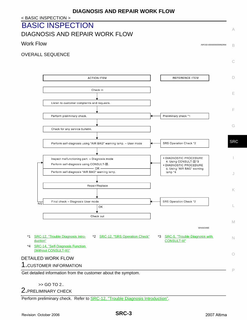
Work Flow INFOID:0000000000992994
OVERALL SEQUENCE
DETAILED WORK FLOW
1.CUSTOMER INFORMATION
Get detailed information from the customer about the symptom.
>> GO TO 2..
2.PRELIMINARY CHECK
Perform preliminary check. Refer to SRC-12, "Trouble Diagnosis Introduction".
*1 SRC-12, "Trouble Diagnosis Intro-duction"
*2 SRC-12, "SRS Operation Check" *3 SRC-5, "Trouble Diagnosis with CONSULT-III"
*4 SRC-14, "Self-Diagnosis Function (Without CONSULT-III)"
WHIA0348E
SRC-3
DIAGNOSIS AND REPAIR WORK FLOW
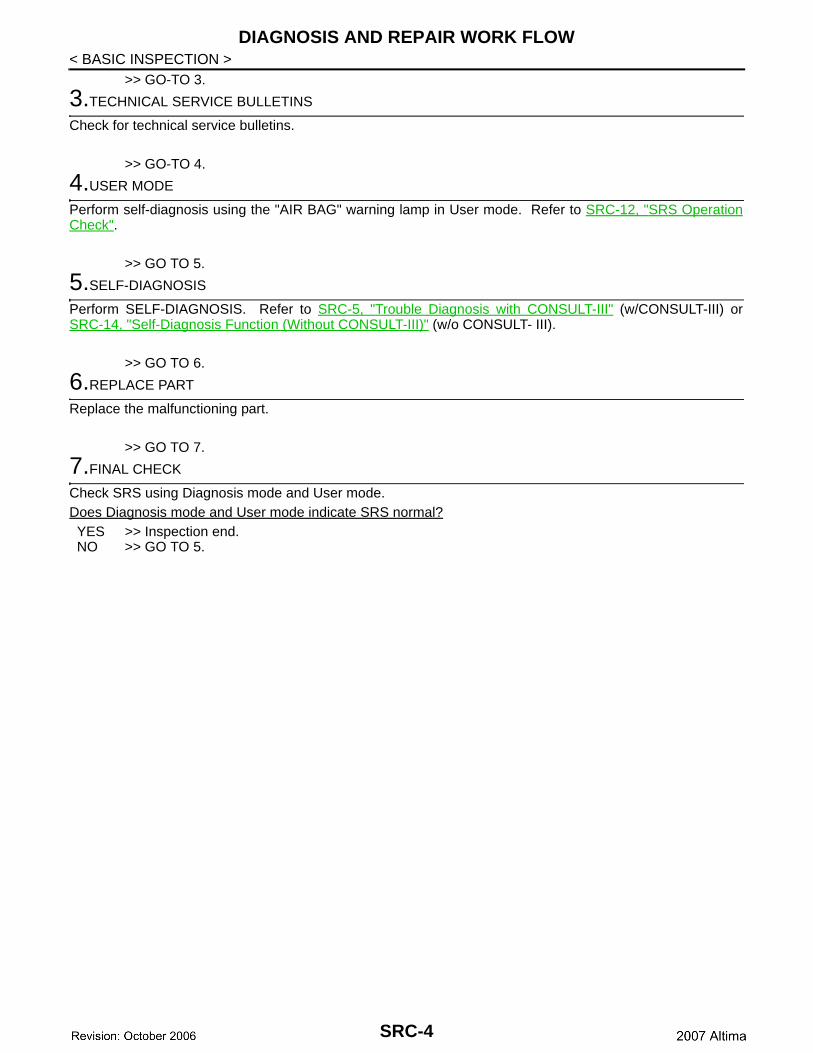
< BASIC INSPECTION >>> GO-TO 3.
3.TECHNICAL SERVICE BULLETINS
Check for technical service bulletins.
>> GO-TO 4.
4.USER MODE
Perform self-diagnosis using the "AIR BAG" warning lamp in User mode. Refer to SRC-12, "SRS OperationCheck".
>> GO TO 5.
5.SELF-DIAGNOSIS
Perform SELF-DIAGNOSIS. Refer to SRC-5, "Trouble Diagnosis with CONSULT-III" (w/CONSULT-III) orSRC-14, "Self-Diagnosis Function (Without CONSULT-III)" (w/o CONSULT- III).
>> GO TO 6.
6.REPLACE PART
Replace the malfunctioning part.
>> GO TO 7.
7.FINAL CHECK
Check SRS using Diagnosis mode and User mode.Does Diagnosis mode and User mode indicate SRS normal?YES >> Inspection end.NO >> GO TO 5.
SRC-4
INTERMITTENTS INCIDENT
C
D
E
F
G
I
J
K
L
M
A
B
RC
N
O
P
< BASIC INSPECTION >
S
INTERMITTENTS INCIDENT
Inspection Procedure INFOID:0000000000992995
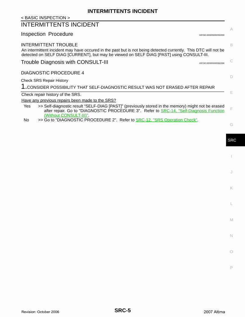
INTERMITTENT TROUBLEAn intermittent incident may have occured in the past but is not being detected currently. This DTC will not bedetected on SELF DIAG [CURRENT], but may be viewed on SELF DIAG [PAST] using CONSULT-III.
Trouble Diagnosis with CONSULT-III INFOID:0000000000992996
DIAGNOSTIC PROCEDURE 4
Check SRS Repair History
1.CONSIDER POSSIBILITY THAT SELF-DIAGNOSTIC RESULT WAS NOT ERASED AFTER REPAIR
Check repair history of the SRS.Have any previous repairs been made to the SRS?Yes >> Self-diagnostic result “SELF-DIAG [PAST]” (previously stored in the memory) might not be erased
after repair. Go to "DIAGNOSTIC PROCEDURE 3". Refer to SRC-14, "Self-Diagnosis Function(Without CONSULT-III)".
No >> Go to "DIAGNOSTIC PROCEDURE 2". Refer to SRC-12, "SRS Operation Check".
SRC-5
SRS AIR BAG SYSTEM
< FUNCTION DIAGNOSIS >FUNCTION DIAGNOSISSRS AIR BAG SYSTEM
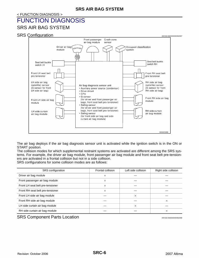
SRS Configuration INFOID:0000000000992997
The air bag deploys if the air bag diagnosis sensor unit is activated while the ignition switch is in the ON orSTART position.The collision modes for which supplemental restraint systems are activated are different among the SRS sys-tems. For example, the driver air bag module, front passenger air bag module and front seat belt pre-tension-ers are activated in a frontal collision but not in a side collision.SRS configurations for some collision modes are as follows:
SRS Component Parts Location INFOID:0000000000992998
WHIA0186E
SRS configuration Frontal collision Left side collision Right side collision
Driver air bag module × — —
Front passenger air bag module × — —
Front LH seat belt pre-tensioner × — —
Front RH seat belt pre-tensioner × — —
Front LH side air bag module — × —
Front RH side air bag module — — ×
LH side curtain air bag module — × —
RH side curtain air bag module — — ×
SRC-6
SRS AIR BAG SYSTEM
C
D
E
F
G
I
J
K
L
M
A
B
RC
N
O
P
< FUNCTION DIAGNOSIS >
S
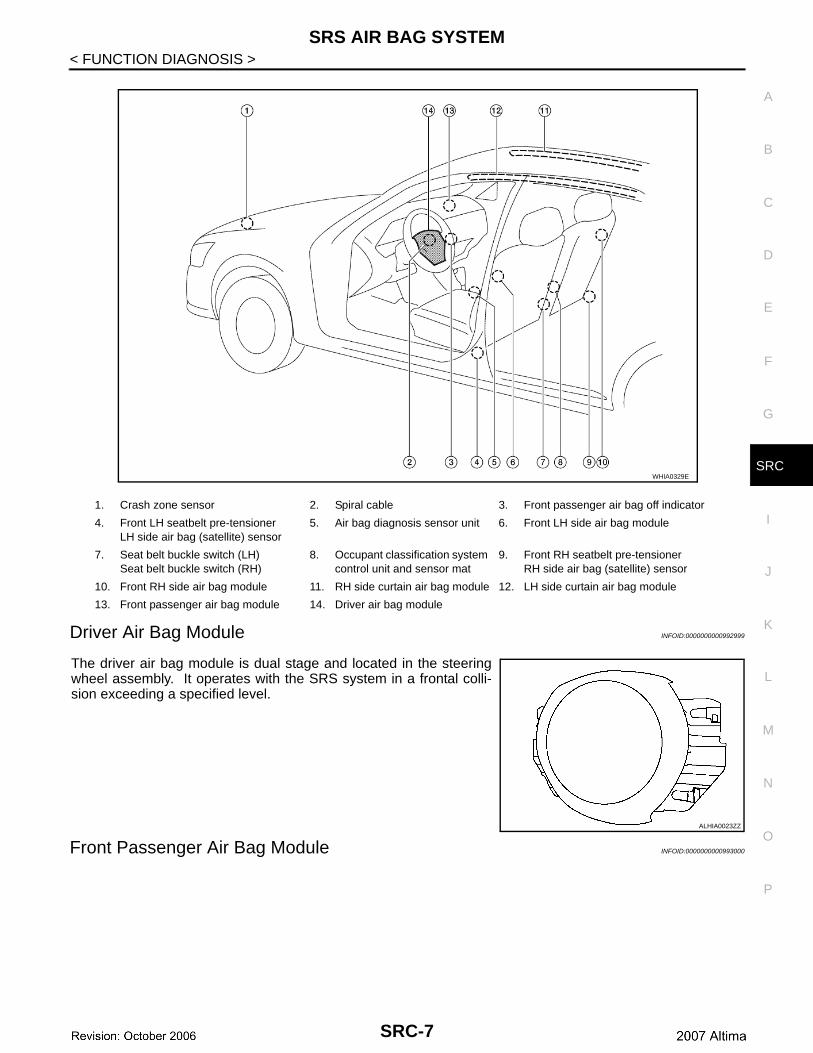
Driver Air Bag Module INFOID:0000000000992999
The driver air bag module is dual stage and located in the steeringwheel assembly. It operates with the SRS system in a frontal colli-sion exceeding a specified level.
Front Passenger Air Bag Module INFOID:0000000000993000
1. Crash zone sensor 2. Spiral cable 3. Front passenger air bag off indicator
4. Front LH seatbelt pre-tensionerLH side air bag (satellite) sensor
5. Air bag diagnosis sensor unit 6. Front LH side air bag module
7. Seat belt buckle switch (LH)Seat belt buckle switch (RH)
8. Occupant classification system control unit and sensor mat
9. Front RH seatbelt pre-tensionerRH side air bag (satellite) sensor
10. Front RH side air bag module 11. RH side curtain air bag module 12. LH side curtain air bag module
13. Front passenger air bag module 14. Driver air bag module
WHIA0329E
ALHIA0023ZZ
SRC-7
SRS AIR BAG SYSTEM
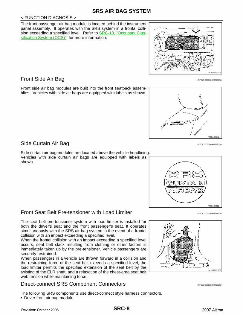
< FUNCTION DIAGNOSIS >The front passenger air bag module is located behind the instrumentpanel assembly. It operates with the SRS system in a frontal colli-sion exceeding a specified level. Refer to SRC-10, "Occupant Clas-sification System (OCS)" for more information.Front Side Air Bag INFOID:0000000000993001
Front side air bag modules are built into the front seatback assem-blies. Vehicles with side air bags are equipped with labels as shown.
Side Curtain Air Bag INFOID:0000000000993002
Side curtain air bag modules are located above the vehicle headlining.Vehicles with side curtain air bags are equipped with labels asshown.
Front Seat Belt Pre-tensioner with Load Limiter INFOID:0000000000993003
The seat belt pre-tensioner system with load limiter is installed forboth the driver's seat and the front passenger's seat. It operatessimultaneously with the SRS air bag system in the event of a frontalcollision with an impact exceeding a specified level.When the frontal collision with an impact exceeding a specified leveloccurs, seat belt slack resulting from clothing or other factors isimmediately taken up by the pre-tensioner. Vehicle passengers aresecurely restrained.When passengers in a vehicle are thrown forward in a collision andthe restraining force of the seat belt exceeds a specified level, theload limiter permits the specified extension of the seat belt by thetwisting of the ELR shaft, and a relaxation of the chest-area seat beltweb tension while maintaining force.
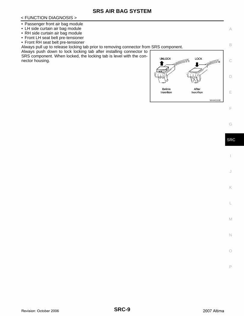
Direct-connect SRS Component Connectors INFOID:0000000000993004
The following SRS components use direct-connect style harness connectors.• Driver front air bag module
ALHIA0024ZZ
WHIA0327E
WHIA0041E
ALHIA0025ZZ
SRC-8
SRS AIR BAG SYSTEM
C
D
E
F
G
I
J
K
L
M
A
B
RC
N
O
P
< FUNCTION DIAGNOSIS >
S
• Passenger front air bag module• LH side curtain air bag module• RH side curtain air bag module• Front LH seat belt pre-tensioner• Front RH seat belt pre-tensionerAlways pull up to release locking tab prior to removing connector from SRS component.Always push down to lock locking tab after installing connector toSRS component. When locked, the locking tab is level with the con-nector housing.
WHIA0103E
SRC-9
OCCUPANT CLASSIFICATION SYSTEM
< FUNCTION DIAGNOSIS >OCCUPANT CLASSIFICATION SYSTEM
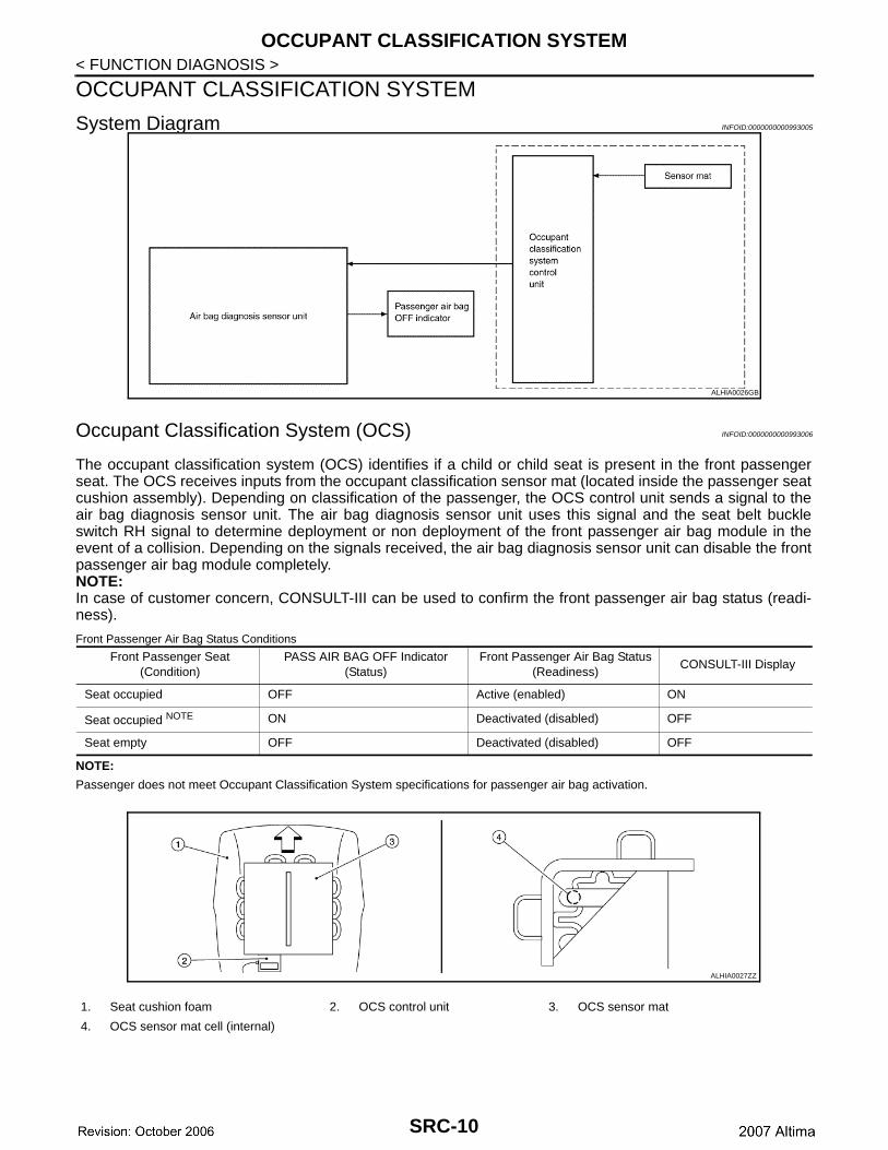
System Diagram INFOID:0000000000993005
Occupant Classification System (OCS) INFOID:0000000000993006
The occupant classification system (OCS) identifies if a child or child seat is present in the front passengerseat. The OCS receives inputs from the occupant classification sensor mat (located inside the passenger seatcushion assembly). Depending on classification of the passenger, the OCS control unit sends a signal to theair bag diagnosis sensor unit. The air bag diagnosis sensor unit uses this signal and the seat belt buckleswitch RH signal to determine deployment or non deployment of the front passenger air bag module in theevent of a collision. Depending on the signals received, the air bag diagnosis sensor unit can disable the frontpassenger air bag module completely.NOTE:In case of customer concern, CONSULT-III can be used to confirm the front passenger air bag status (readi-ness).
Front Passenger Air Bag Status Conditions
NOTE:
Passenger does not meet Occupant Classification System specifications for passenger air bag activation.
ALHIA0026GB
Front Passenger Seat(Condition)
PASS AIR BAG OFF Indicator(Status)
Front Passenger Air Bag Status(Readiness)
CONSULT-III Display
Seat occupied OFF Active (enabled) ON
Seat occupied NOTE ON Deactivated (disabled) OFF
Seat empty OFF Deactivated (disabled) OFF
1. Seat cushion foam 2. OCS control unit 3. OCS sensor mat
4. OCS sensor mat cell (internal)
ALHIA0027ZZ
SRC-10
PASSENGER SEAT BELT WARNING SYSTEM
C
D
E
F
G
I
J
K
L
M
A
B
RC
N
O
P
< FUNCTION DIAGNOSIS >
S
PASSENGER SEAT BELT WARNING SYSTEM
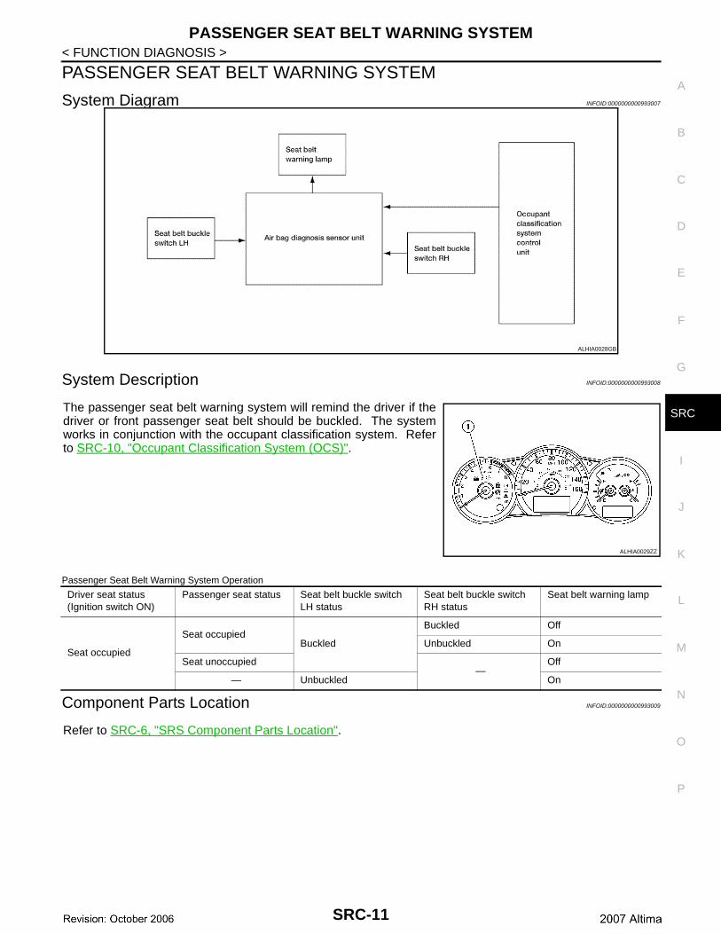
System Diagram INFOID:0000000000993007
System Description INFOID:0000000000993008
The passenger seat belt warning system will remind the driver if thedriver or front passenger seat belt should be buckled. The systemworks in conjunction with the occupant classification system. Referto SRC-10, "Occupant Classification System (OCS)".
Passenger Seat Belt Warning System Operation
Component Parts Location INFOID:0000000000993009
Refer to SRC-6, "SRS Component Parts Location".
ALHIA0028GB
ALHIA0029ZZ
Driver seat status(Ignition switch ON)
Passenger seat status Seat belt buckle switch LH status
Seat belt buckle switch RH status
Seat belt warning lamp
Seat occupied
Seat occupiedBuckled
Buckled Off
Unbuckled On
Seat unoccupied—
Off
— Unbuckled On
SRC-11
ON BOARD DIAGNOSTIC (OBD) SYSTEM
< FUNCTION DIAGNOSIS >ON BOARD DIAGNOSTIC (OBD) SYSTEM
Trouble Diagnosis Introduction INFOID:0000000000993010
CAUTION:• Do not use electrical test equipment on any circuit related to the SRS unless instructed to do so in
this Service Manual. SRS wiring harnesses can be identified by yellow and/or orange harness con-nectors.
• Do not attempt to repair, splice or modify SRS wiring harnesses. If a harness is damaged, replace itwith a new one.
• Keep ground connections clean.
DIAGNOSIS FUNCTIONThe SRS self-diagnosis results can be read by using “AIR BAG” warning lamp and/or CONSULT-III. The User mode is exclusively prepared for the customer (driver). This mode warns the driver of a system mal-function through the operation of the “AIR BAG” warning lamp.The Diagnosis mode allows the technician to locate and inspect the malfunctioning part.The mode applications for the “AIR BAG” warning lamp and CONSULT-III are as follows:
HOW TO PERFORM TROUBLE DIAGNOSES FOR QUICK AND ACCURATE REPAIRA good understanding of the malfunction conditions can make troubleshooting faster and more accurate.In general, each customer feels differently about a malfunction. It is important to fully understand the symp-toms or conditions for a customer complaint.
Information From CustomerWHAT - Vehicle modelWHEN - Date, FrequenciesWHERE - Road conditionsHOW - Operating conditions, Symptoms
Preliminary CheckCheck that the following parts are in good order.• Battery (Refer to PG-2, "How to Handle Battery".)• Fuse (Refer to SRC-59, "Wiring Diagram".)• System component-to-harness connections
SRS Operation Check INFOID:0000000000993011
DIAGNOSTIC PROCEDURE 1
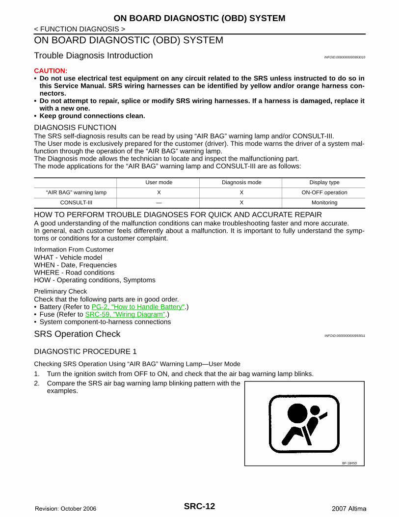
Checking SRS Operation Using “AIR BAG” Warning Lamp—User Mode
1. Turn the ignition switch from OFF to ON, and check that the air bag warning lamp blinks.2. Compare the SRS air bag warning lamp blinking pattern with the
examples.
User mode Diagnosis mode Display type
“AIR BAG” warning lamp X X ON-OFF operation
CONSULT-III — X Monitoring
BF-1845D
SRC-12
ON BOARD DIAGNOSTIC (OBD) SYSTEM
C
D
E
F
G
I
J
K
L
M
A
B
RC
N
O
P
< FUNCTION DIAGNOSIS >
S
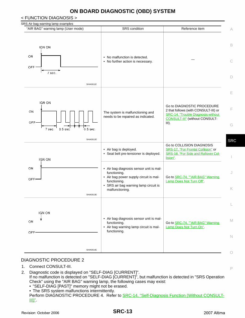
SRS Air bag warning lamp examples
DIAGNOSTIC PROCEDURE 21. Connect CONSULT-III.2. Diagnostic code is displayed on "SELF-DIAG [CURRENT]".
If no malfunction is detected on "SELF-DIAG [CURRENT]", but malfunction is detected in "SRS OperationCheck" using the "AIR BAG" warning lamp, the following cases may exist:• "SELF-DIAG [PAST]" memory might not be erased.• The SRS system malfunctions intermittently.Perform DIAGNOSTIC PROCEDURE 4. Refer to SRC-14, "Self-Diagnosis Function (Without CONSULT-III)".
“AIR BAG” warning lamp (User mode) SRS condition Reference item
• No malfunction is detected.• No further action is necessary.
—
The system is malfunctioning and needs to be repaired as indicated.
Go to DIAGNOSTIC PROCEDURE 2 that follows (with CONSULT-III) or SRC-14, "Trouble Diagnosis without CONSULT-III" (without CONSULT-III).
• Air bag is deployed.• Seat belt pre-tensioner is deployed.
Go to COLLISION DIAGNOSIS SRS-17, "For Frontal Collision" or SRS-18, "For Side and Rollover Col-lision".
• Air bag diagnosis sensor unit is mal-functioning.
• Air bag power supply circuit is mal-functioning.
• SRS air bag warning lamp circuit is malfunctioning.
Go to SRC-74, ""AIR BAG" Warning Lamp Does Not Turn Off".
• Air bag diagnosis sensor unit is mal-functioning.
• Air bag warning lamp circuit is mal-functioning.
Go to SRC-74, ""AIR BAG" Warning Lamp Does Not Turn On".
SHIA0011E
SHIA0012E
SHIA0013E
SHIA0014E
SRC-13
ON BOARD DIAGNOSTIC (OBD) SYSTEM
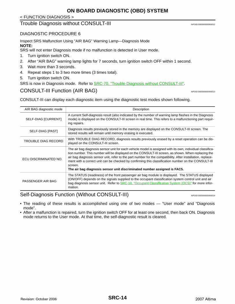
< FUNCTION DIAGNOSIS >Trouble Diagnosis without CONSULT-III INFOID:0000000000993012
DIAGNOSTIC PROCEDURE 6
Inspect SRS Malfunction Using "AIR BAG" Warning Lamp—Diagnosis ModeNOTE:SRS will not enter Diagnosis mode if no malfunction is detected in User mode.1. Turn ignition switch ON.2. After “AIR BAG” warning lamp lights for 7 seconds, turn ignition switch OFF within 1 second.3. Wait more than 3 seconds.4. Repeat steps 1 to 3 two more times (3 times total).5. Turn ignition switch ON.SRS is now in Diagnosis mode. Refer to SRC-70, "Trouble Diagnosis without CONSULT-III".
CONSULT-III Function (AIR BAG) INFOID:0000000000993013
CONSULT-III can display each diagnostic item using the diagnostic test modes shown following.
Self-Diagnosis Function (Without CONSULT-III) INFOID:0000000000993014
• The reading of these results is accomplished using one of two modes — “User mode” and “Diagnosismode”.
• After a malfunction is repaired, turn the ignition switch OFF for at least one second, then back ON. Diagnosismode returns to the User mode. At that time, the self-diagnostic result is cleared.
AIR BAG diagnostic mode Description
SELF-DIAG [CURRENT]A current Self-diagnosis result (also indicated by the number of warning lamp flashes in the Diagnosis mode) is displayed on the CONSULT-III screen in real time. This refers to a malfunctioning part requir-ing repairs.
SELF-DIAG [PAST]Diagnosis results previously stored in the memory are displayed on the CONSULT-III screen. The stored results will remain until memory erasing is executed.
TROUBLE DIAG RECORDWith TROUBLE DIAG RECORD, diagnosis results previously erased by a reset operation can be dis-played on the CONSULT-III screen.
ECU DISCRIMINATED NO.
The air bag diagnosis sensor unit for each vehicle model is assigned with its own, individual classifica-tion number. This number will be displayed on the CONSULT-III screen, as shown. When replacing the air bag diagnosis sensor unit, refer to the part number for the compatibility. After installation, replace-ment with a correct unit can be checked by confirming this classification number on the CONSULT-III screen.The air bag diagnosis sensor unit discriminated number assigned is FAC5.
PASSENGER AIR BAG
The STATUS (readiness) of the front passenger air bag module is displayed. The STATUS displayed (ON/OFF) depends on the signals supplied to the occupant classification system control unit and air bag diagnosis sensor unit. Refer to SRC-10, "Occupant Classification System (OCS)" for more infor-mation.
SRC-14
ON BOARD DIAGNOSTIC (OBD) SYSTEM
C
D
E
F
G
I
J
K
L
M
A
B
RC
N
O
P
< FUNCTION DIAGNOSIS >
S
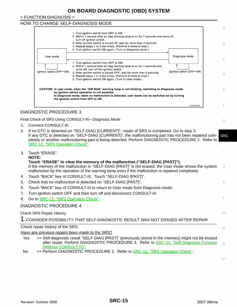
HOW TO CHANGE SELF-DIAGNOSIS MODE
DIAGNOSTIC PROCEDURE 3
Final Check of SRS Using CONSULT-III—Diagnosis Mode
1. Connect CONSULT-III.2. If no DTC is detected on “SELF-DIAG [CURRENT]”, repair of SRS is completed. Go to step 3.
If any DTC is detected on “SELF-DIAG [CURRENT]”, the malfunctioning part has not been repaired com-pletely or another malfunctioning part is being detected. Perform DIAGNOSTIC PROCEDURE 2. Refer toSRC-12, "SRS Operation Check".
3. Touch “ERASE”.NOTE:Touch “ERASE” to clear the memory of the malfunction (“SELF-DIAG [PAST]”).If the memory of the malfunction in “SELF-DIAG [PAST]” is not erased, the User mode shows the systemmalfunction by the operation of the warning lamp even if the malfunction is repaired completely.
4. Touch “BACK” key of CONSULT-III. Touch “SELF-DIAG [PAST]”.5. Check that no malfunction is detected on “SELF-DIAG [PAST]”.6. Touch “BACK” key of CONSULT-III to return to User mode from Diagnosis mode.7. Turn ignition switch OFF and then turn off and disconnect CONSULT-III.8. Go to SRC-12, "SRS Operation Check".
DIAGNOSTIC PROCEDURE 4
Check SRS Repair History
1.CONSIDER POSSIBILITY THAT SELF-DIAGNOSTIC RESULT WAS NOT ERASED AFTER REPAIR
Check repair history of the SRS.Have any previous repairs been made to the SRS?Yes >> Self-diagnostic result “SELF-DIAG [PAST]” (previously stored in the memory) might not be erased
after repair. Perform DIAGNOSTIC PROCEDURE 3. Refer to SRC-14, "Self-Diagnosis Function(Without CONSULT-III)".
No >> Perform DIAGNOSTIC PROCEDURE 2. Refer to SRC-12, "SRS Operation Check".
SHIA0183E
SRC-15
B1049 – B1052, B1054 – B1057 DRIVER AIRBAG MODULE
< COMPONENT DIAGNOSIS >COMPONENT DIAGNOSISB1049 – B1052, B1054 – B1057 DRIVER AIRBAG MODULE
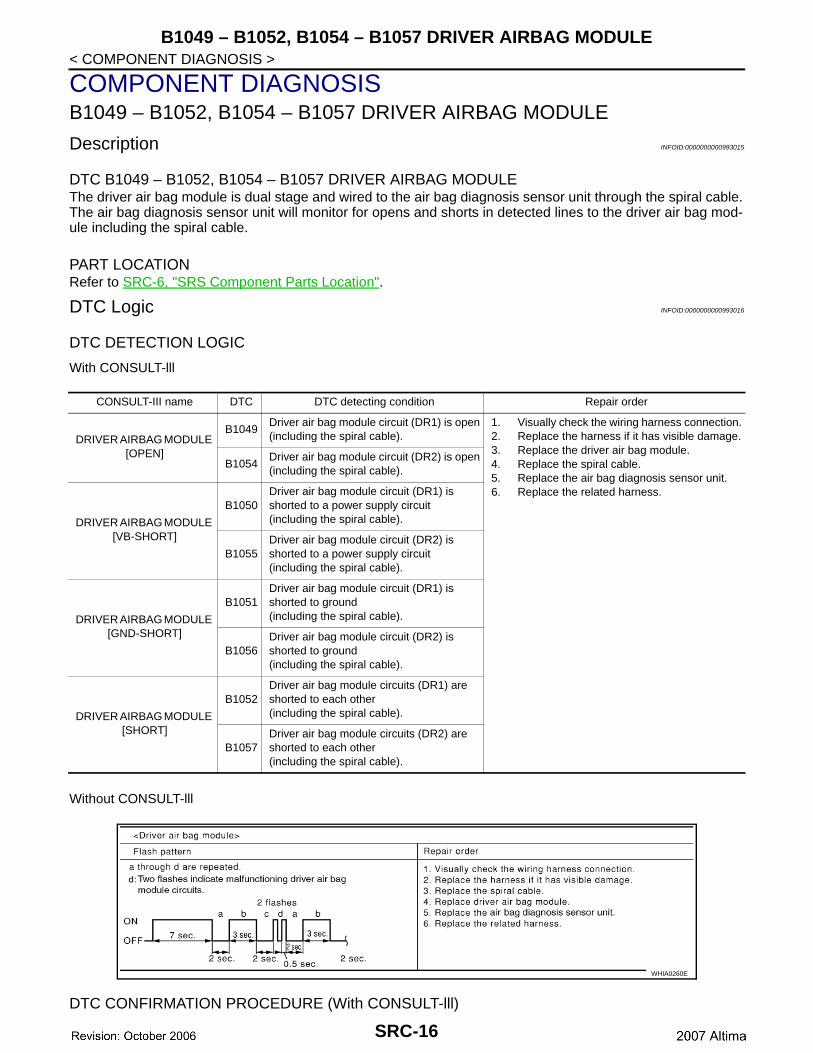
Description INFOID:0000000000993015
DTC B1049 – B1052, B1054 – B1057 DRIVER AIRBAG MODULEThe driver air bag module is dual stage and wired to the air bag diagnosis sensor unit through the spiral cable.The air bag diagnosis sensor unit will monitor for opens and shorts in detected lines to the driver air bag mod-ule including the spiral cable.
PART LOCATIONRefer to SRC-6, "SRS Component Parts Location".
DTC Logic INFOID:0000000000993016
DTC DETECTION LOGIC
With CONSULT-lll
Without CONSULT-lll
DTC CONFIRMATION PROCEDURE (With CONSULT-lll)
CONSULT-III name DTC DTC detecting condition Repair order
DRIVER AIRBAG MODULE [OPEN]
B1049Driver air bag module circuit (DR1) is open(including the spiral cable).
1. Visually check the wiring harness connection.2. Replace the harness if it has visible damage.3. Replace the driver air bag module.4. Replace the spiral cable.5. Replace the air bag diagnosis sensor unit.6. Replace the related harness.
B1054Driver air bag module circuit (DR2) is open(including the spiral cable).
DRIVER AIRBAG MODULE [VB-SHORT]
B1050Driver air bag module circuit (DR1) is shorted to a power supply circuit(including the spiral cable).
B1055Driver air bag module circuit (DR2) is shorted to a power supply circuit(including the spiral cable).
DRIVER AIRBAG MODULE [GND-SHORT]
B1051Driver air bag module circuit (DR1) is shorted to ground(including the spiral cable).
B1056Driver air bag module circuit (DR2) is shorted to ground(including the spiral cable).
DRIVER AIRBAG MODULE [SHORT]
B1052Driver air bag module circuits (DR1) are shorted to each other(including the spiral cable).
B1057Driver air bag module circuits (DR2) are shorted to each other(including the spiral cable).
WHIA0260E
SRC-16
B1049 – B1052, B1054 – B1057 DRIVER AIRBAG MODULE
C
D
E
F
G
I
J
K
L
M
A
B
RC
N
O
P
< COMPONENT DIAGNOSIS >
S
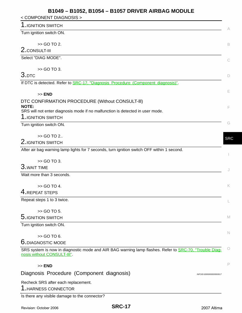
1.IGNITION SWITCH
Turn ignition switch ON.
>> GO TO 2.
2.CONSULT-III
Select "DIAG MODE".
>> GO TO 3.
3.DTC
If DTC is detected. Refer to SRC-17, "Diagnosis Procedure (Component diagnosis)".
>> END
DTC CONFIRMATION PROCEDURE (Without CONSULT-lll)NOTE:SRS will not enter diagnosis mode if no malfunction is detected in user mode.
1.IGNITION SWITCH
Turn ignition switch ON.
>> GO TO 2..
2.IGNITION SWITCH
After air bag warning lamp lights for 7 seconds, turn ignition switch OFF within 1 second.
>> GO TO 3.
3.WAIT TIME
Wait more than 3 seconds.
>> GO TO 4.
4.REPEAT STEPS
Repeat steps 1 to 3 twice.
>> GO TO 5.
5.IGNITION SWITCH
Turn ignition switch ON.
>> GO TO 6.
6.DIAGNOSTIC MODE
SRS system is now in diagnostic mode and AIR BAG warning lamp flashes. Refer to SRC-70, "Trouble Diag-nosis without CONSULT-III".
>> END
Diagnosis Procedure (Component diagnosis) INFOID:0000000000993017
Recheck SRS after each replacement.
1.HARNESS CONNECTOR
Is there any visible damage to the connector?
SRC-17
B1049 – B1052, B1054 – B1057 DRIVER AIRBAG MODULE
< COMPONENT DIAGNOSIS >YES or NOYES >> Replace the harness..NO >> GO TO 2..2.WIRING HARNESS
Is there any visible damage to the harness?YES or NOYES >> Replace the harness.NO >> GO TO 3.
3.DRIVER AIR BAG MODULE
Replace the driver air bag module. Refer to SRS-4, "Removal and Installation".
>> GO TO 4.
4.SPIRAL CABLE
Replace the spiral cable. Refer to SRS-6, "Removal and Installation".
>> GO TO 5.
5.AIR BAG DIAGNOSIS SENSOR UNIT
Replace the air bag diagnosis sensor unit. Refer to SRS-14, "Removal and Installation".
>> GO TO 6.
6.RELATED HARNESS
Replace the related harness.
>> END
SRC-18
B1065 – B1068, B1070 – B1073 PASSENGER AIRBAG MODULE
C
D
E
F
G
I
J
K
L
M
A
B
RC
N
O
P
< COMPONENT DIAGNOSIS >
S
B1065 – B1068, B1070 – B1073 PASSENGER AIRBAG MODULE
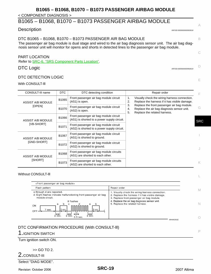
Description INFOID:0000000000993018
DTC B1065 – B1068, B1070 – B1073 PASSENGER AIR BAG MODULEThe passenger air bag module is dual stage and wired to the air bag diagnosis sensor unit. The air bag diag-nosis sensor unit will monitor for opens and shorts in detected lines to the passenger air bag module.
PART LOCATIONRefer to SRC-6, "SRS Component Parts Location".
DTC Logic INFOID:0000000000993019
DTC DETECTION LOGIC
With CONSULT-lll
Without CONSULT-lll
DTC CONFIRMATION PROCEDURE (With CONSULT-lll)
1.IGNITION SWITCH
Turn ignition switch ON.
>> GO TO 2.
2.CONSULT-III
Select "DIAG MODE".
CONSULT-III name DTC DTC detecting condition Repair order
ASSIST A/B MODULE [OPEN]
B1065Front passenger air bag module circuit (AS1) is open.
1. Visually check the wiring harness connection.2. Replace the harness if it has visible damage.3. Replace the front passenger air bag module.4. Replace the air bag diagnosis sensor unit.5. Replace the related harness.
B1070Front passenger air bag module circuit (AS2) is open.
ASSIST A/B MODULE [VB-SHORT]
B1066Front passenger air bag module circuit (AS1) is shorted to a power supply circuit.
B1071Front passenger air bag module circuit (AS2) is shorted to a power supply circuit.
ASSIST A/B MODULE [GND-SHORT]
B1067Front passenger air bag module circuit (AS1) is shorted to ground.
B1072Front passenger air bag module circuit (AS2) is shorted to ground.
ASSIST A/B MODULE [SHORT]
B1068Front passenger air bag module circuits (AS1) are shorted to each other.
B1073Front passenger air bag module circuits (AS2) are shorted to each other.
WHIA0261E
SRC-19
B1065 – B1068, B1070 – B1073 PASSENGER AIRBAG MODULE
< COMPONENT DIAGNOSIS >>> GO TO 3.
3.DTC
If DTC is detected. Refer to SRC-20, "Diagnosis Procedure (Component diagnosis)".
>> END
DTC CONFIRMATION PROCEDURE (Without CONSULT-lll)NOTE:SRS will not enter diagnosis mode if no malfunction is detected in user mode.
1.IGNITION SWITCH
Turn ignition switch ON.
>> GO TO 2..
2.IGNITION SWITCH
After air bag warning lamp lights for 7 seconds, turn ignition switch OFF within 1 second.
>> GO TO 3.
3.WAIT TIME
Wait more than 3 seconds.
>> GO TO 4.
4.REPEAT STEPS
Repeat steps 1 to 3 twice.
>> GO TO 5.
5.IGNITION SWITCH
Turn ignition switch ON.
>> GO TO 6.
6.DIAGNOSTIC MODE
SRS system is now in diagnostic mode and AIR BAG warning lamp flashes. Refer to SRC-70, "Trouble Diag-nosis without CONSULT-III".
>> END
Diagnosis Procedure (Component diagnosis) INFOID:0000000000993020
Recheck SRS after each replacement.
1.HARNESS CONNECTOR
Is there any visible damage to the connector?YES or NOYES >> Replace the harness..NO >> GO TO 2..
2.WIRING HARNESS
Is there any visible damage to the harness?YES or NOYES >> Replace the harness.
SRC-20
B1065 – B1068, B1070 – B1073 PASSENGER AIRBAG MODULE
C
D
E
F
G
I
J
K
L
M
A
B
RC
N
O
P
< COMPONENT DIAGNOSIS >
S
NO >> GO TO 3.
3.FRONT PASSENGER AIR BAG MODULE
Replace the front passenger air bag module. Refer to SRS-8, "Removal and Installation".
>> GO TO 4.
4.AIR BAG DIAGNOSIS SENSOR UNIT
Replace the air bag diagnosis sensor unit. Refer to SRS-14, "Removal and Installation".
>> GO TO 5.
5.RELATED HARNESS
Replace the related harness.
>> END
SRC-21
B1134 – B1137 SIDE AIRBAG MODULE LH
< COMPONENT DIAGNOSIS >B1134 – B1137 SIDE AIRBAG MODULE LH
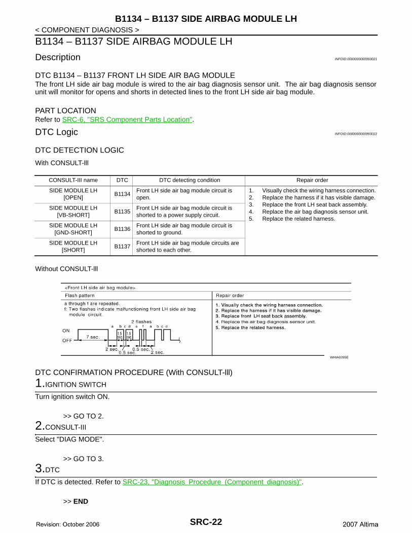
Description INFOID:0000000000993021
DTC B1134 – B1137 FRONT LH SIDE AIR BAG MODULEThe front LH side air bag module is wired to the air bag diagnosis sensor unit. The air bag diagnosis sensorunit will monitor for opens and shorts in detected lines to the front LH side air bag module.
PART LOCATIONRefer to SRC-6, "SRS Component Parts Location".
DTC Logic INFOID:0000000000993022
DTC DETECTION LOGIC
With CONSULT-lll
Without CONSULT-lll
DTC CONFIRMATION PROCEDURE (With CONSULT-lll)
1.IGNITION SWITCH
Turn ignition switch ON.
>> GO TO 2.
2.CONSULT-III
Select "DIAG MODE".
>> GO TO 3.
3.DTC
If DTC is detected. Refer to SRC-23, "Diagnosis Procedure (Component diagnosis)".
>> END
CONSULT-III name DTC DTC detecting condition Repair order
SIDE MODULE LH [OPEN]
B1134Front LH side air bag module circuit is open.
1. Visually check the wiring harness connection.2. Replace the harness if it has visible damage.3. Replace the front LH seat back assembly.4. Replace the air bag diagnosis sensor unit.5. Replace the related harness.
SIDE MODULE LH [VB-SHORT]
B1135Front LH side air bag module circuit is shorted to a power supply circuit.
SIDE MODULE LH [GND-SHORT]
B1136Front LH side air bag module circuit is shorted to ground.
SIDE MODULE LH [SHORT]
B1137Front LH side air bag module circuits are shorted to each other.
WHIA0265E
SRC-22

B1134 – B1137 SIDE AIRBAG MODULE LH
C
D
E
F
G
I
J
K
L
M
A
B
RC
N
O
P
< COMPONENT DIAGNOSIS >
S
DTC CONFIRMATION PROCEDURE (Without CONSULT-lll)NOTE:SRS will not enter diagnosis mode if no malfunction is detected in user mode.
1.IGNITION SWITCH
Turn ignition switch ON.
>> GO TO 2..
2.IGNITION SWITCH
After air bag warning lamp lights for 7 seconds, turn ignition switch OFF within 1 second.
>> GO TO 3.
3.WAIT TIME
Wait more than 3 seconds.
>> GO TO 4.
4.REPEAT STEPS
Repeat steps 1 to 3 twice.
>> GO TO 5.
5.IGNITION SWITCH
Turn ignition switch ON.
>> GO TO 6.
6.DIAGNOSTIC MODE
SRS system is now in diagnostic mode and AIR BAG warning lamp flashes. Refer to SRC-70, "Trouble Diag-nosis without CONSULT-III".
>> END
Diagnosis Procedure (Component diagnosis) INFOID:0000000000993023
Recheck SRS after each replacement.
1.HARNESS CONNECTOR
Is there any visible damage to the connector?YES or NOYES >> Replace the harness..NO >> GO TO 2..
2.WIRING HARNESS
Is there any visible damage to the harness?YES or NOYES >> Replace the harness.NO >> GO TO 3.
3.FRONT LH SIDE AIR BAG MODULE
Replace the front LH seat back assembly. Refer to SE-19, "Removal and Installation".
>> GO TO 4.
4.AIR BAG DIAGNOSIS SENSOR UNIT
SRC-23
B1134 – B1137 SIDE AIRBAG MODULE LH
< COMPONENT DIAGNOSIS >Replace the air bag diagnosis sensor unit. Refer to SRS-14, "Removal and Installation".>> GO TO 5.
5.RELATED HARNESS
Replace the related harness.
>> END
SRC-24
B1129 – B1132 SIDE AIRBAG MODULE RH
C
D
E
F
G
I
J
K
L
M
A
B
RC
N
O
P
< COMPONENT DIAGNOSIS >
S
B1129 – B1132 SIDE AIRBAG MODULE RH
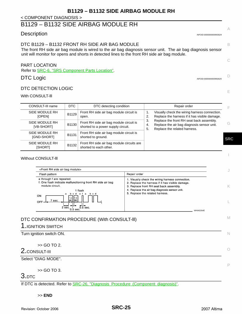
Description INFOID:0000000000993024
DTC B1129 – B1132 FRONT RH SIDE AIR BAG MODULEThe front RH side air bag module is wired to the air bag diagnosis sensor unit. The air bag diagnosis sensorunit will monitor for opens and shorts in detected lines to the front RH side air bag module.
PART LOCATIONRefer to SRC-6, "SRS Component Parts Location".
DTC Logic INFOID:0000000000993025
DTC DETECTION LOGIC
With CONSULT-lll
Without CONSULT-lll
DTC CONFIRMATION PROCEDURE (With CONSULT-lll)
1.IGNITION SWITCH
Turn ignition switch ON.
>> GO TO 2.
2.CONSULT-III
Select "DIAG MODE".
>> GO TO 3.
3.DTC
If DTC is detected. Refer to SRC-26, "Diagnosis Procedure (Component diagnosis)".
>> END
CONSULT-III name DTC DTC detecting condition Repair order
SIDE MODULE RH [OPEN]
B1129Front RH side air bag module circuit is open.
1. Visually check the wiring harness connection.2. Replace the harness if it has visible damage.3. Replace the front RH seat back assembly.4. Replace the air bag diagnosis sensor unit.5. Replace the related harness.
SIDE MODULE RH [VB-SHORT]
B1130Front RH side air bag module circuit is shorted to a power supply circuit.
SIDE MODULE RH [GND-SHORT]
B1131Front RH side air bag module circuit is shorted to ground.
SIDE MODULE RH [SHORT]
B1132Front RH side air bag module circuits are shorted to each other.
WHIA0264E
SRC-25
B1129 – B1132 SIDE AIRBAG MODULE RH
< COMPONENT DIAGNOSIS >DTC CONFIRMATION PROCEDURE (Without CONSULT-lll)NOTE:SRS will not enter diagnosis mode if no malfunction is detected in user mode.
1.IGNITION SWITCH
Turn ignition switch ON.
>> GO TO 2..
2.IGNITION SWITCH
After air bag warning lamp lights for 7 seconds, turn ignition switch OFF within 1 second.
>> GO TO 3.
3.WAIT TIME
Wait more than 3 seconds.
>> GO TO 4.
4.REPEAT STEPS
Repeat steps 1 to 3 twice.
>> GO TO 5.
5.IGNITION SWITCH
Turn ignition switch ON.
>> GO TO 6.
6.DIAGNOSTIC MODE
SRS system is now in diagnostic mode and AIR BAG warning lamp flashes. Refer to SRC-70, "Trouble Diag-nosis without CONSULT-III".
>> END
Diagnosis Procedure (Component diagnosis) INFOID:0000000000993026
Recheck SRS after each replacement.
1.HARNESS CONNECTOR
Is there any visible damage to the connector?YES or NOYES >> Replace the harness..NO >> GO TO 2..
2.WIRING HARNESS
Is there any visible damage to the harness?YES or NOYES >> Replace the harness.NO >> GO TO 3.
3.FRONT RH SIDE AIR BAG MODULE
Replace the front RH seat back assembly. Refer to SE-19, "Removal and Installation".
>> GO TO 4.
4.AIR BAG DIAGNOSIS SENSOR UNIT
SRC-26
B1129 – B1132 SIDE AIRBAG MODULE RH
C
D
E
F
G
I
J
K
L
M
A
B
RC
N
O
P
< COMPONENT DIAGNOSIS >
S
Replace the air bag diagnosis sensor unit. Refer to SRS-14, "Removal and Installation".
>> GO TO 5.
5.RELATED HARNESS
Replace the related harness.
>> END
SRC-27
B1150 – B1153 SIDE CURTAIN AIR BAG MODULE LH
< COMPONENT DIAGNOSIS >B1150 – B1153 SIDE CURTAIN AIR BAG MODULE LH
Description INFOID:0000000000993027
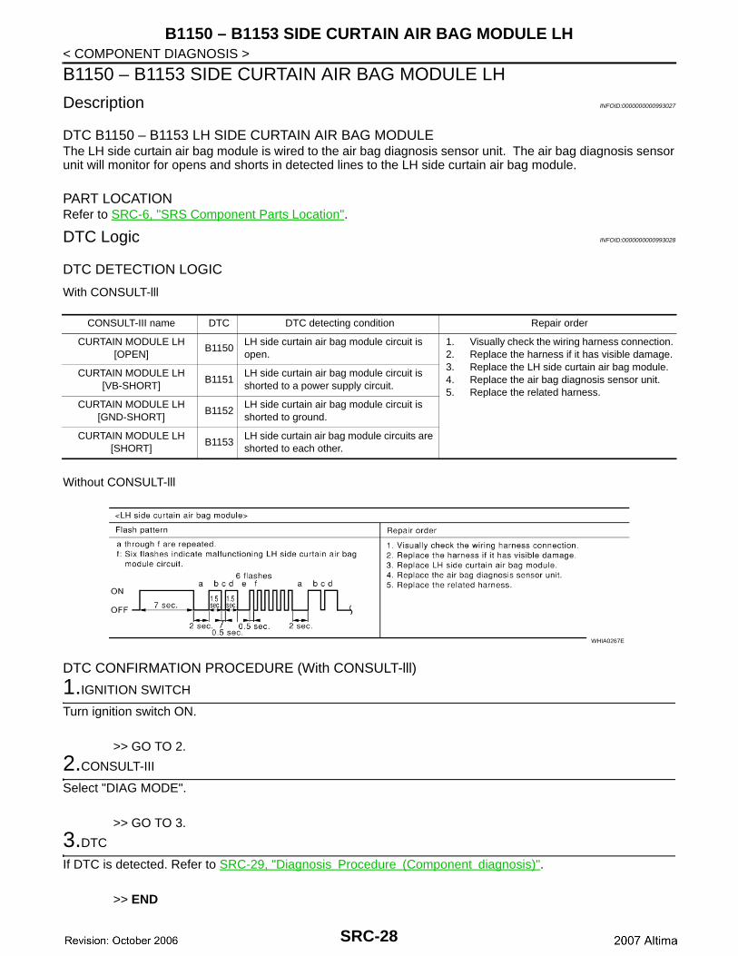
DTC B1150 – B1153 LH SIDE CURTAIN AIR BAG MODULEThe LH side curtain air bag module is wired to the air bag diagnosis sensor unit. The air bag diagnosis sensorunit will monitor for opens and shorts in detected lines to the LH side curtain air bag module.
PART LOCATIONRefer to SRC-6, "SRS Component Parts Location".
DTC Logic INFOID:0000000000993028
DTC DETECTION LOGIC
With CONSULT-lll
Without CONSULT-lll
DTC CONFIRMATION PROCEDURE (With CONSULT-lll)
1.IGNITION SWITCH
Turn ignition switch ON.
>> GO TO 2.
2.CONSULT-III
Select "DIAG MODE".
>> GO TO 3.
3.DTC
If DTC is detected. Refer to SRC-29, "Diagnosis Procedure (Component diagnosis)".
>> END
CONSULT-III name DTC DTC detecting condition Repair order
CURTAIN MODULE LH [OPEN]
B1150LH side curtain air bag module circuit is open.
1. Visually check the wiring harness connection.2. Replace the harness if it has visible damage.3. Replace the LH side curtain air bag module.4. Replace the air bag diagnosis sensor unit.5. Replace the related harness.
CURTAIN MODULE LH [VB-SHORT]
B1151LH side curtain air bag module circuit is shorted to a power supply circuit.
CURTAIN MODULE LH [GND-SHORT]
B1152LH side curtain air bag module circuit is shorted to ground.
CURTAIN MODULE LH [SHORT]
B1153LH side curtain air bag module circuits are shorted to each other.
WHIA0267E
SRC-28
B1150 – B1153 SIDE CURTAIN AIR BAG MODULE LH
C
D
E
F
G
I
J
K
L
M
A
B
RC
N
O
P
< COMPONENT DIAGNOSIS >
S
DTC CONFIRMATION PROCEDURE (Without CONSULT-lll)NOTE:SRS will not enter diagnosis mode if no malfunction is detected in user mode.
1.IGNITION SWITCH
Turn ignition switch ON.
>> GO TO 2..
2.IGNITION SWITCH
After air bag warning lamp lights for 7 seconds, turn ignition switch OFF within 1 second.
>> GO TO 3.
3.WAIT TIME
Wait more than 3 seconds.
>> GO TO 4.
4.REPEAT STEPS
Repeat steps 1 to 3 twice.
>> GO TO 5.
5.IGNITION SWITCH
Turn ignition switch ON.
>> GO TO 6.
6.DIAGNOSTIC MODE
SRS system is now in diagnostic mode and AIR BAG warning lamp flashes. Refer to SRC-70, "Trouble Diag-nosis without CONSULT-III".
>> END
Diagnosis Procedure (Component diagnosis) INFOID:0000000000993029
Recheck SRS after each replacement.
1.HARNESS CONNECTOR
Is there any visible damage to the connector?YES or NOYES >> Replace the harness..NO >> GO TO 2..
2.WIRING HARNESS
Is there any visible damage to the harness?YES or NOYES >> Replace the harness.NO >> GO TO 3.
3.LH SIDE CURTAIN AIR BAG MODULE
Replace the LH side curtain air bag module. Refer to SRS-10, "Removal and Installation".
>> GO TO 4.
4.AIR BAG DIAGNOSIS SENSOR UNIT
SRC-29
B1150 – B1153 SIDE CURTAIN AIR BAG MODULE LH
< COMPONENT DIAGNOSIS >Replace the air bag diagnosis sensor unit. SRS-14, "Removal and Installation".>> GO TO 5.
5.RELATED HARNESS
Replace the related harness.
>> END
SRC-30
B1145 – B1148 SIDE CURTAIN AIR BAG MODULE RH
C
D
E
F
G
I
J
K
L
M
A
B
RC
N
O
P
< COMPONENT DIAGNOSIS >
S
B1145 – B1148 SIDE CURTAIN AIR BAG MODULE RH
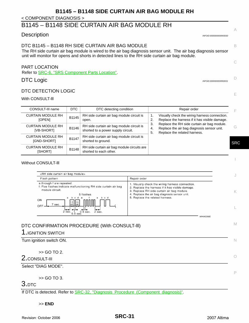
Description INFOID:0000000000993030
DTC B1145 – B1148 RH SIDE CURTAIN AIR BAG MODULEThe RH side curtain air bag module is wired to the air bag diagnosis sensor unit. The air bag diagnosis sensorunit will monitor for opens and shorts in detected lines to the RH side curtain air bag module.
PART LOCATIONRefer to SRC-6, "SRS Component Parts Location".
DTC Logic INFOID:0000000000993031
DTC DETECTION LOGIC
With CONSULT-lll
Without CONSULT-lll
DTC CONFIRMATION PROCEDURE (With CONSULT-lll)
1.IGNITION SWITCH
Turn ignition switch ON.
>> GO TO 2.
2.CONSULT-III
Select "DIAG MODE".
>> GO TO 3.
3.DTC
If DTC is detected. Refer to SRC-32, "Diagnosis Procedure (Component diagnosis)".
>> END
CONSULT-III name DTC DTC detecting condition Repair order
CURTAIN MODULE RH [OPEN]
B1145RH side curtain air bag module circuit is open.
1. Visually check the wiring harness connection.2. Replace the harness if it has visible damage.3. Replace the RH side curtain air bag module.4. Replace the air bag diagnosis sensor unit.5. Replace the related harness.
CURTAIN MODULE RH [VB-SHORT]
B1146RH side curtain air bag module circuit is shorted to a power supply circuit.
CURTAIN MODULE RH [GND-SHORT]
B1147RH side curtain air bag module circuit is shorted to ground.
CURTAIN MODULE RH [SHORT]
B1148RH side curtain air bag module circuits are shorted to each other.
WHIA0266E
SRC-31
B1145 – B1148 SIDE CURTAIN AIR BAG MODULE RH
< COMPONENT DIAGNOSIS >DTC CONFIRMATION PROCEDURE (Without CONSULT-lll)NOTE:SRS will not enter diagnosis mode if no malfunction is detected in user mode.
1.IGNITION SWITCH
Turn ignition switch ON.
>> GO TO 2..
2.IGNITION SWITCH
After air bag warning lamp lights for 7 seconds, turn ignition switch OFF within 1 second.
>> GO TO 3.
3.WAIT TIME
Wait more than 3 seconds.
>> GO TO 4.
4.REPEAT STEPS
Repeat steps 1 to 3 twice.
>> GO TO 5.
5.IGNITION SWITCH
Turn ignition switch ON.
>> GO TO 6.
6.DIAGNOSTIC MODE
SRS system is now in diagnostic mode and AIR BAG warning lamp flashes. Refer to SRC-70, "Trouble Diag-nosis without CONSULT-III".
>> END
Diagnosis Procedure (Component diagnosis) INFOID:0000000000993032
Recheck SRS after each replacement.
1.HARNESS CONNECTOR
Is there any visible damage to the connector?YES or NOYES >> Replace the harness..NO >> GO TO 2..
2.WIRING HARNESS
Is there any visible damage to the harness?YES or NOYES >> Replace the harness.NO >> GO TO 3.
3.RH SIDE CURTAIN AIR BAG MODULE
Replace the RH side curtain air bag module. Refer to SRS-10, "Removal and Installation".
>> GO TO 4.
4.AIR BAG DIAGNOSIS SENSOR UNIT
SRC-32

B1145 – B1148 SIDE CURTAIN AIR BAG MODULE RH
C
D
E
F
G
I
J
K
L
M
A
B
RC
N
O
P
< COMPONENT DIAGNOSIS >
S
Replace the air bag diagnosis sensor unit. Refer to SRS-14, "Removal and Installation".
>> GO TO 5.
5.RELATED HARNESS
Replace the related harness.
>> END
SRC-33
B1086 – B1089 SEAT BELT PRE-TENSIONER LH
< COMPONENT DIAGNOSIS >B1086 – B1089 SEAT BELT PRE-TENSIONER LH
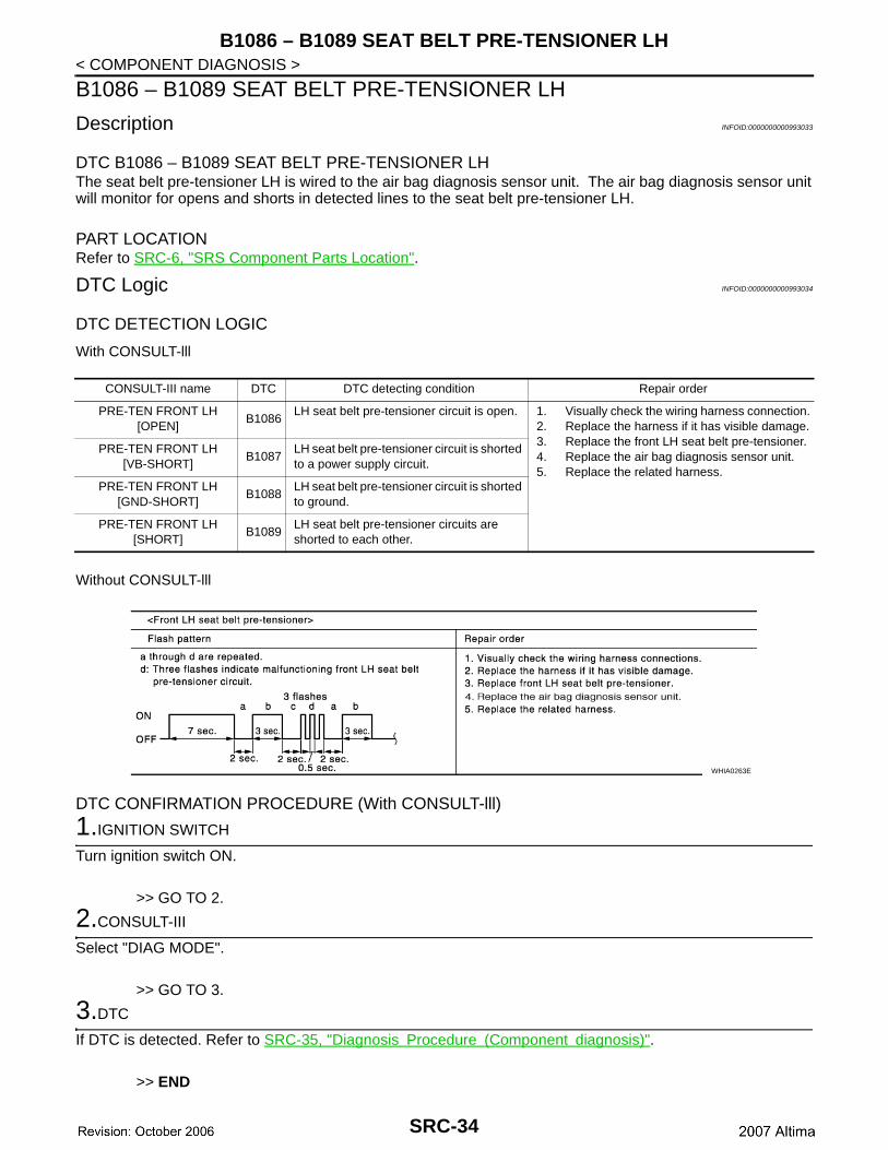
Description INFOID:0000000000993033
DTC B1086 – B1089 SEAT BELT PRE-TENSIONER LHThe seat belt pre-tensioner LH is wired to the air bag diagnosis sensor unit. The air bag diagnosis sensor unitwill monitor for opens and shorts in detected lines to the seat belt pre-tensioner LH.
PART LOCATIONRefer to SRC-6, "SRS Component Parts Location".
DTC Logic INFOID:0000000000993034
DTC DETECTION LOGIC
With CONSULT-lll
Without CONSULT-lll
DTC CONFIRMATION PROCEDURE (With CONSULT-lll)
1.IGNITION SWITCH
Turn ignition switch ON.
>> GO TO 2.
2.CONSULT-III
Select "DIAG MODE".
>> GO TO 3.
3.DTC
If DTC is detected. Refer to SRC-35, "Diagnosis Procedure (Component diagnosis)".
>> END
CONSULT-III name DTC DTC detecting condition Repair order
PRE-TEN FRONT LH [OPEN]
B1086LH seat belt pre-tensioner circuit is open. 1. Visually check the wiring harness connection.
2. Replace the harness if it has visible damage.3. Replace the front LH seat belt pre-tensioner.4. Replace the air bag diagnosis sensor unit.5. Replace the related harness.
PRE-TEN FRONT LH [VB-SHORT]
B1087LH seat belt pre-tensioner circuit is shorted to a power supply circuit.
PRE-TEN FRONT LH [GND-SHORT]
B1088LH seat belt pre-tensioner circuit is shorted to ground.
PRE-TEN FRONT LH [SHORT]
B1089LH seat belt pre-tensioner circuits are shorted to each other.
WHIA0263E
SRC-34
B1086 – B1089 SEAT BELT PRE-TENSIONER LH
C
D
E
F
G
I
J
K
L
M
A
B
RC
N
O
P
< COMPONENT DIAGNOSIS >
S
DTC CONFIRMATION PROCEDURE (Without CONSULT-lll)NOTE:SRS will not enter diagnosis mode if no malfunction is detected in user mode.
1.IGNITION SWITCH
Turn ignition switch ON.
>> GO TO 2..
2.IGNITION SWITCH
After air bag warning lamp lights for 7 seconds, turn ignition switch OFF within 1 second.
>> GO TO 3.
3.WAIT TIME
Wait more than 3 seconds.
>> GO TO 4.
4.REPEAT STEPS
Repeat steps 1 to 3 twice.
>> GO TO 5.
5.IGNITION SWITCH
Turn ignition switch ON.
>> GO TO 6.
6.DIAGNOSTIC MODE
SRS system is now in diagnostic mode and AIR BAG warning lamp flashes. Refer to SRC-70, "Trouble Diag-nosis without CONSULT-III".
>> END
Diagnosis Procedure (Component diagnosis) INFOID:0000000000993035
Recheck SRS after each replacement.
1.HARNESS CONNECTOR
Is there any visible damage to the connector?YES or NOYES >> Replace the harness..NO >> GO TO 2..
2.WIRING HARNESS
Is there any visible damage to the harness?YES or NOYES >> Replace the harness.NO >> GO TO 3.
3.FRONT LH SEAT BELT PRE-TENSIONER
Replace the front LH seat belt pre-tensioner. Refer to SB-6, "SEAT BELT RETRACTOR : Removal and Instal-lation".
>> GO TO 4.
SRC-35
B1086 – B1089 SEAT BELT PRE-TENSIONER LH
< COMPONENT DIAGNOSIS >4.AIR BAG DIAGNOSIS SENSOR UNIT
Replace the air bag diagnosis sensor unit. Refer to SRS-14, "Removal and Installation".
>> GO TO 5.
5.RELATED HARNESS
Replace the related harness.
>> END
SRC-36
B1081 – B1084 SEAT BELT PRE-TENSIONER RH
C
D
E
F
G
I
J
K
L
M
A
B
RC
N
O
P
< COMPONENT DIAGNOSIS >
S
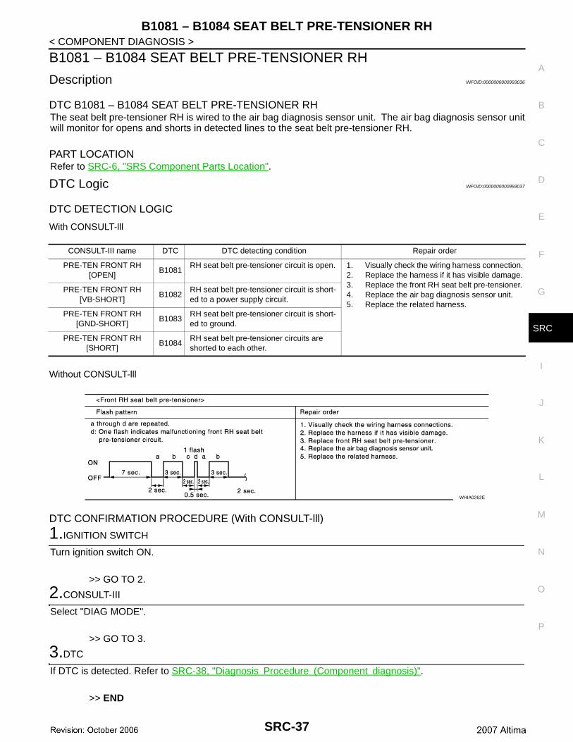
B1081 – B1084 SEAT BELT PRE-TENSIONER RH
Description INFOID:0000000000993036
DTC B1081 – B1084 SEAT BELT PRE-TENSIONER RHThe seat belt pre-tensioner RH is wired to the air bag diagnosis sensor unit. The air bag diagnosis sensor unitwill monitor for opens and shorts in detected lines to the seat belt pre-tensioner RH.
PART LOCATIONRefer to SRC-6, "SRS Component Parts Location".
DTC Logic INFOID:0000000000993037
DTC DETECTION LOGIC
With CONSULT-lll
Without CONSULT-lll
DTC CONFIRMATION PROCEDURE (With CONSULT-lll)
1.IGNITION SWITCH
Turn ignition switch ON.
>> GO TO 2.
2.CONSULT-III
Select "DIAG MODE".
>> GO TO 3.
3.DTC
If DTC is detected. Refer to SRC-38, "Diagnosis Procedure (Component diagnosis)".
>> END
CONSULT-III name DTC DTC detecting condition Repair order
PRE-TEN FRONT RH [OPEN]
B1081RH seat belt pre-tensioner circuit is open. 1. Visually check the wiring harness connection.
2. Replace the harness if it has visible damage.3. Replace the front RH seat belt pre-tensioner.4. Replace the air bag diagnosis sensor unit.5. Replace the related harness.
PRE-TEN FRONT RH [VB-SHORT]
B1082RH seat belt pre-tensioner circuit is short-ed to a power supply circuit.
PRE-TEN FRONT RH [GND-SHORT]
B1083RH seat belt pre-tensioner circuit is short-ed to ground.
PRE-TEN FRONT RH [SHORT]
B1084RH seat belt pre-tensioner circuits are shorted to each other.
WHIA0262E
SRC-37
B1081 – B1084 SEAT BELT PRE-TENSIONER RH
< COMPONENT DIAGNOSIS >DTC CONFIRMATION PROCEDURE (Without CONSULT-lll)NOTE:SRS will not enter diagnosis mode if no malfunction is detected in user mode.
1.IGNITION SWITCH
Turn ignition switch ON.
>> GO TO 2..
2.IGNITION SWITCH
After air bag warning lamp lights for 7 seconds, turn ignition switch OFF within 1 second.
>> GO TO 3.
3.WAIT TIME
Wait more than 3 seconds.
>> GO TO 4.
4.REPEAT STEPS
Repeat steps 1 to 3 twice.
>> GO TO 5.
5.IGNITION SWITCH
Turn ignition switch ON.
>> GO TO 6.
6.DIAGNOSTIC MODE
SRS system is now in diagnostic mode and AIR BAG warning lamp flashes. Refer to SRC-70, "Trouble Diag-nosis without CONSULT-III".
>> END
Diagnosis Procedure (Component diagnosis) INFOID:0000000000993038
Recheck SRS after each replacement.
1.HARNESS CONNECTOR
Is there any visible damage to the connector?YES or NOYES >> Replace the harness..NO >> GO TO 2..
2.WIRING HARNESS
Is there any visible damage to the harness?YES or NOYES >> Replace the harness.NO >> GO TO 3.
3.FRONT RH SEAT BELT PRE-TENSIONER
Replace the front RH seat belt pre-tensioner. Refer to SB-6, "SEAT BELT RETRACTOR : Removal and Instal-lation".
>> GO TO 4.
SRC-38
B1081 – B1084 SEAT BELT PRE-TENSIONER RH
C
D
E
F
G
I
J
K
L
M
A
B
RC
N
O
P
< COMPONENT DIAGNOSIS >
S
4.AIR BAG DIAGNOSIS SENSOR UNIT
Replace the air bag diagnosis sensor unit. Refer to SRS-14, "Removal and Installation".
>> GO TO 5.
5.RELATED HARNESS
Replace the related harness.
>> END
SRC-39
B1033 – B1035 CRASH ZONE SENSOR
< COMPONENT DIAGNOSIS >B1033 – B1035 CRASH ZONE SENSOR
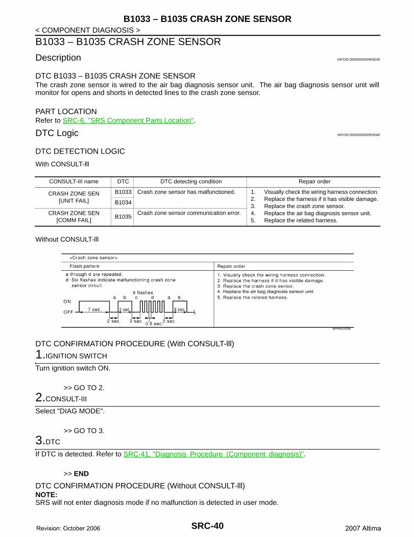
Description INFOID:0000000000993039
DTC B1033 – B1035 CRASH ZONE SENSORThe crash zone sensor is wired to the air bag diagnosis sensor unit. The air bag diagnosis sensor unit willmonitor for opens and shorts in detected lines to the crash zone sensor.
PART LOCATIONRefer to SRC-6, "SRS Component Parts Location".
DTC Logic INFOID:0000000000993040
DTC DETECTION LOGIC
With CONSULT-lll
Without CONSULT-lll
DTC CONFIRMATION PROCEDURE (With CONSULT-lll)
1.IGNITION SWITCH
Turn ignition switch ON.
>> GO TO 2.
2.CONSULT-III
Select "DIAG MODE".
>> GO TO 3.
3.DTC
If DTC is detected. Refer to SRC-41, "Diagnosis Procedure (Component diagnosis)".
>> END
DTC CONFIRMATION PROCEDURE (Without CONSULT-lll)NOTE:SRS will not enter diagnosis mode if no malfunction is detected in user mode.
CONSULT-III name DTC DTC detecting condition Repair order
CRASH ZONE SEN[UNIT FAIL]
B1033 Crash zone sensor has malfunctioned. 1. Visually check the wiring harness connection.2. Replace the harness if it has visible damage.3. Replace the crash zone sensor.4. Replace the air bag diagnosis sensor unit.5. Replace the related harness.
B1034
CRASH ZONE SEN[COMM FAIL]
B1035Crash zone sensor communication error.
WHIA0200E
SRC-40

B1033 – B1035 CRASH ZONE SENSOR
C
D
E
F
G
I
J
K
L
M
A
B
RC
N
O
P
< COMPONENT DIAGNOSIS >
S
1.IGNITION SWITCH
Turn ignition switch ON.
>> GO TO 2..
2.IGNITION SWITCH
After air bag warning lamp lights for 7 seconds, turn ignition switch OFF within 1 second.
>> GO TO 3.
3.WAIT TIME
Wait more than 3 seconds.
>> GO TO 4.
4.REPEAT STEPS
Repeat steps 1 to 3 twice.
>> GO TO 5.
5.IGNITION SWITCH
Turn ignition switch ON.
>> GO TO 6.
6.DIAGNOSTIC MODE
SRS system is now in diagnostic mode and AIR BAG warning lamp flashes. Refer to SRC-70, "Trouble Diag-nosis without CONSULT-III".
>> END
Diagnosis Procedure (Component diagnosis) INFOID:0000000000993041
Recheck SRS after each replacement.
1.HARNESS CONNECTOR
Is there any visible damage to the connector?YES or NOYES >> Replace the harness..NO >> GO TO 2..
2.WIRING HARNESS
Is there any visible damage to the harness?YES or NOYES >> Replace the harness.NO >> GO TO 3.
3.CRASH ZONE SENSOR
Replace the crash zone sensor. Refer to SRS-12, "Removal and Installation".
>> GO TO 4.
4.AIR BAG DIAGNOSIS SENSOR UNIT
Replace the air bag diagnosis sensor unit. Refer to SRS-14, "Removal and Installation".
SRC-41
B1033 – B1035 CRASH ZONE SENSOR
< COMPONENT DIAGNOSIS >>> GO TO 5.
5.RELATED HARNESS
Replace the related harness.
>> END
SRC-42
B1118 – B1120 SATELLITE SENSOR LH
C
D
E
F
G
I
J
K
L
M
A
B
RC
N
O
P
< COMPONENT DIAGNOSIS >
S
B1118 – B1120 SATELLITE SENSOR LH
Description INFOID:0000000000993042
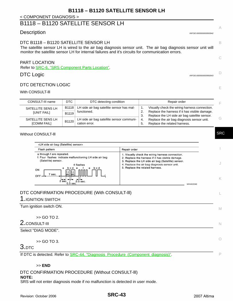
DTC B1118 – B1120 SATELLITE SENSOR LHThe satellite sensor LH is wired to the air bag diagnosis sensor unit. The air bag diagnosis sensor unit willmonitor the satellite sensor LH for internal failures and it's circuits for communication errors.
PART LOCATIONRefer to SRC-6, "SRS Component Parts Location".
DTC Logic INFOID:0000000000993043
DTC DETECTION LOGIC
With CONSULT-lll
Without CONSULT-lll
DTC CONFIRMATION PROCEDURE (With CONSULT-lll)
1.IGNITION SWITCH
Turn ignition switch ON.
>> GO TO 2.
2.CONSULT-III
Select "DIAG MODE".
>> GO TO 3.
3.DTC
If DTC is detected. Refer to SRC-44, "Diagnosis Procedure (Component diagnosis)".
>> END
DTC CONFIRMATION PROCEDURE (Without CONSULT-lll)NOTE:SRS will not enter diagnosis mode if no malfunction is detected in user mode.
CONSULT-III name DTC DTC detecting condition Repair order
SATELLITE SENS LH[UNIT FAIL]
B1118 LH side air bag satellite sensor has mal-functioned.
1. Visually check the wiring harness connection.2. Replace the harness if it has visible damage.3. Replace the LH side air bag satellite sensor.4. Replace the air bag diagnosis sensor unit.5. Replace the related harness.
B1119
SATELLITE SENS LH[COMM FAIL]
B1120LH side air bag satellite sensor communi-cation error.
WHIA0204E
SRC-43
B1118 – B1120 SATELLITE SENSOR LH
< COMPONENT DIAGNOSIS >1.IGNITION SWITCH
Turn ignition switch ON.
>> GO TO 2..
2.IGNITION SWITCH
After air bag warning lamp lights for 7 seconds, turn ignition switch OFF within 1 second.
>> GO TO 3.
3.WAIT TIME
Wait more than 3 seconds.
>> GO TO 4.
4.REPEAT STEPS
Repeat steps 1 to 3 twice.
>> GO TO 5.
5.IGNITION SWITCH
Turn ignition switch ON.
>> GO TO 6.
6.DIAGNOSTIC MODE
SRS system is now in diagnostic mode and AIR BAG warning lamp flashes. Refer to SRC-70, "Trouble Diag-nosis without CONSULT-III".
>> END
Diagnosis Procedure (Component diagnosis) INFOID:0000000000993044
Recheck SRS after each replacement.
1.HARNESS CONNECTOR
Is there any visible damage to the connector?YES or NOYES >> Replace the harness..NO >> GO TO 2..
2.WIRING HARNESS
Is there any visible damage to the harness?YES or NOYES >> Replace the harness.NO >> GO TO 3.
3.LH SIDE AIR BAG SATELLITE SENSOR
Replace the LH side air bag satellite sensor. Refer to SRS-13, "Removal and Installation".
>> GO TO 4.
4.AIR BAG DIAGNOSIS SENSOR UNIT
Replace the air bag diagnosis sensor unit. Refer to SRS-14, "Removal and Installation".
SRC-44
B1118 – B1120 SATELLITE SENSOR LH
C
D
E
F
G
I
J
K
L
M
A
B
RC
N
O
P
< COMPONENT DIAGNOSIS >
S
>> GO TO 5.
5.RELATED HARNESS
Replace the related harness.
>> END
SRC-45
B1113 – B1115 SATELLITE SENSOR RH
< COMPONENT DIAGNOSIS >B1113 – B1115 SATELLITE SENSOR RH
Description INFOID:0000000000993045
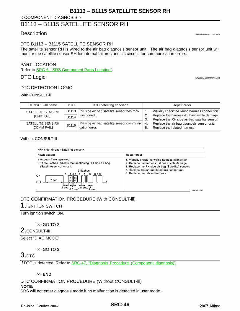
DTC B1113 – B1115 SATELLITE SENSOR RHThe satellite sensor RH is wired to the air bag diagnosis sensor unit. The air bag diagnosis sensor unit willmonitor the satellite sensor RH for internal failures and it's circuits for communication errors.
PART LOCATIONRefer to SRC-6, "SRS Component Parts Location".
DTC Logic INFOID:0000000000993046
DTC DETECTION LOGIC
With CONSULT-lll
Without CONSULT-lll
DTC CONFIRMATION PROCEDURE (With CONSULT-lll)
1.IGNITION SWITCH
Turn ignition switch ON.
>> GO TO 2.
2.CONSULT-III
Select "DIAG MODE".
>> GO TO 3.
3.DTC
If DTC is detected. Refer to SRC-47, "Diagnosis Procedure (Component diagnosis)".
>> END
DTC CONFIRMATION PROCEDURE (Without CONSULT-lll)NOTE:SRS will not enter diagnosis mode if no malfunction is detected in user mode.
CONSULT-III name DTC DTC detecting condition Repair order
SATELLITE SENS RH[UNIT FAIL]
B1113 RH side air bag satellite sensor has mal-functioned.
1. Visually check the wiring harness connection.2. Replace the harness if it has visible damage.3. Replace the RH side air bag satellite sensor.4. Replace the air bag diagnosis sensor unit.5. Replace the related harness.
B1114
SATELLITE SENS RH[COMM FAIL]
B1115RH side air bag satellite sensor communi-cation error.
WHIA0203E
SRC-46
B1113 – B1115 SATELLITE SENSOR RH
C
D
E
F
G
I
J
K
L
M
A
B
RC
N
O
P
< COMPONENT DIAGNOSIS >
S
1.IGNITION SWITCH
Turn ignition switch ON.
>> GO TO 2..
2.IGNITION SWITCH
After air bag warning lamp lights for 7 seconds, turn ignition switch OFF within 1 second.
>> GO TO 3.
3.WAIT TIME
Wait more than 3 seconds.
>> GO TO 4.
4.REPEAT STEPS
Repeat steps 1 to 3 twice.
>> GO TO 5.
5.IGNITION SWITCH
Turn ignition switch ON.
>> GO TO 6.
6.DIAGNOSTIC MODE
SRS system is now in diagnostic mode and AIR BAG warning lamp flashes. Refer to SRC-70, "Trouble Diag-nosis without CONSULT-III".
>> END
Diagnosis Procedure (Component diagnosis) INFOID:0000000000993047
Recheck SRS after each replacement.
1.HARNESS CONNECTOR
Is there any visible damage to the connector?YES or NOYES >> Replace the harness..NO >> GO TO 2..
2.WIRING HARNESS
Is there any visible damage to the harness?YES or NOYES >> Replace the harness.NO >> GO TO 3.
3.RH SIDE AIR BAG SATELLITE SENSOR
Replace the RH side air bag satellite sensor. Refer to SRS-13, "Removal and Installation".
>> GO TO 4.
4.AIR BAG DIAGNOSIS SENSOR UNIT
Replace the air bag diagnosis sensor unit. Refer to SRS-14, "Removal and Installation".
SRC-47
B1113 – B1115 SATELLITE SENSOR RH
< COMPONENT DIAGNOSIS >>> GO TO 5.
5.RELATED HARNESS
Replace the related harness.
>> END
SRC-48
B1XXX AIR BAG DIAGNOSIS SENSOR UNIT
C
D
E
F
G
I
J
K
L
M
A
B
RC
N
O
P
< COMPONENT DIAGNOSIS >
S
B1XXX AIR BAG DIAGNOSIS SENSOR UNIT
Description INFOID:0000000000993048
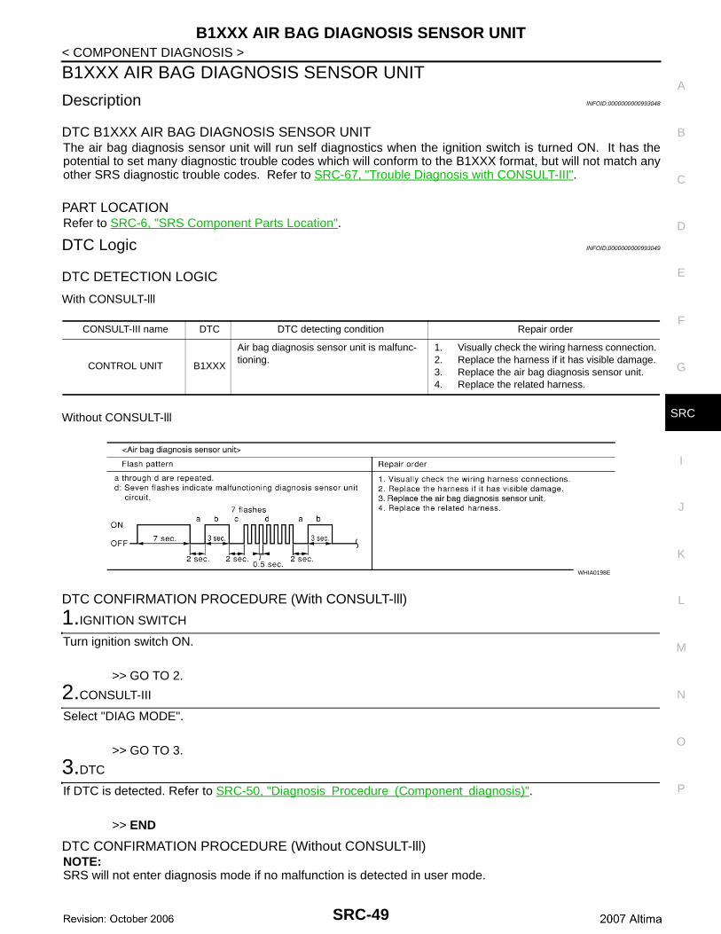
DTC B1XXX AIR BAG DIAGNOSIS SENSOR UNITThe air bag diagnosis sensor unit will run self diagnostics when the ignition switch is turned ON. It has thepotential to set many diagnostic trouble codes which will conform to the B1XXX format, but will not match anyother SRS diagnostic trouble codes. Refer to SRC-67, "Trouble Diagnosis with CONSULT-III".
PART LOCATIONRefer to SRC-6, "SRS Component Parts Location".
DTC Logic INFOID:0000000000993049
DTC DETECTION LOGIC
With CONSULT-lll
Without CONSULT-lll
DTC CONFIRMATION PROCEDURE (With CONSULT-lll)
1.IGNITION SWITCH
Turn ignition switch ON.
>> GO TO 2.
2.CONSULT-III
Select "DIAG MODE".
>> GO TO 3.
3.DTC
If DTC is detected. Refer to SRC-50, "Diagnosis Procedure (Component diagnosis)".
>> END
DTC CONFIRMATION PROCEDURE (Without CONSULT-lll)NOTE:SRS will not enter diagnosis mode if no malfunction is detected in user mode.
CONSULT-III name DTC DTC detecting condition Repair order
CONTROL UNIT B1XXX
Air bag diagnosis sensor unit is malfunc-tioning.
1. Visually check the wiring harness connection.2. Replace the harness if it has visible damage.3. Replace the air bag diagnosis sensor unit.4. Replace the related harness.
WHIA0198E
SRC-49
B1XXX AIR BAG DIAGNOSIS SENSOR UNIT
< COMPONENT DIAGNOSIS >1.IGNITION SWITCH
Turn ignition switch ON.
>> GO TO 2..
2.IGNITION SWITCH
After air bag warning lamp lights for 7 seconds, turn ignition switch OFF within 1 second.
>> GO TO 3.
3.WAIT TIME
Wait more than 3 seconds.
>> GO TO 4.
4.REPEAT STEPS
Repeat steps 1 to 3 twice.
>> GO TO 5.
5.IGNITION SWITCH
Turn ignition switch ON.
>> GO TO 6.
6.DIAGNOSTIC MODE
SRS system is now in diagnostic mode and AIR BAG warning lamp flashes. Refer to SRC-70, "Trouble Diag-nosis without CONSULT-III".
>> END
Diagnosis Procedure (Component diagnosis) INFOID:0000000000993050
Recheck SRS after each replacement.
1.HARNESS CONNECTOR
Is there any visible damage to the connector?YES or NOYES >> Replace the harness..NO >> GO TO 2..
2.WIRING HARNESS
Is there any visible damage to the harness?YES or NOYES >> Replace the harness.NO >> GO TO 3.
3.AIR BAG DIAGNOSIS SENSOR UNIT
Replace the air bag diagnosis sensor unit. Refer to SRS-14, "Removal and Installation".
>> GO TO 4.
4.RELATED HARNESS
Replace the related harness.
SRC-50
B1XXX AIR BAG DIAGNOSIS SENSOR UNIT
C
D
E
F
G
I
J
K
L
M
A
B
RC
N
O
P
< COMPONENT DIAGNOSIS >
S
>> END
SRC-51
B1023 PASSENGER AIR BAG OFF INDICATOR
< COMPONENT DIAGNOSIS >B1023 PASSENGER AIR BAG OFF INDICATOR
Description INFOID:0000000000993051
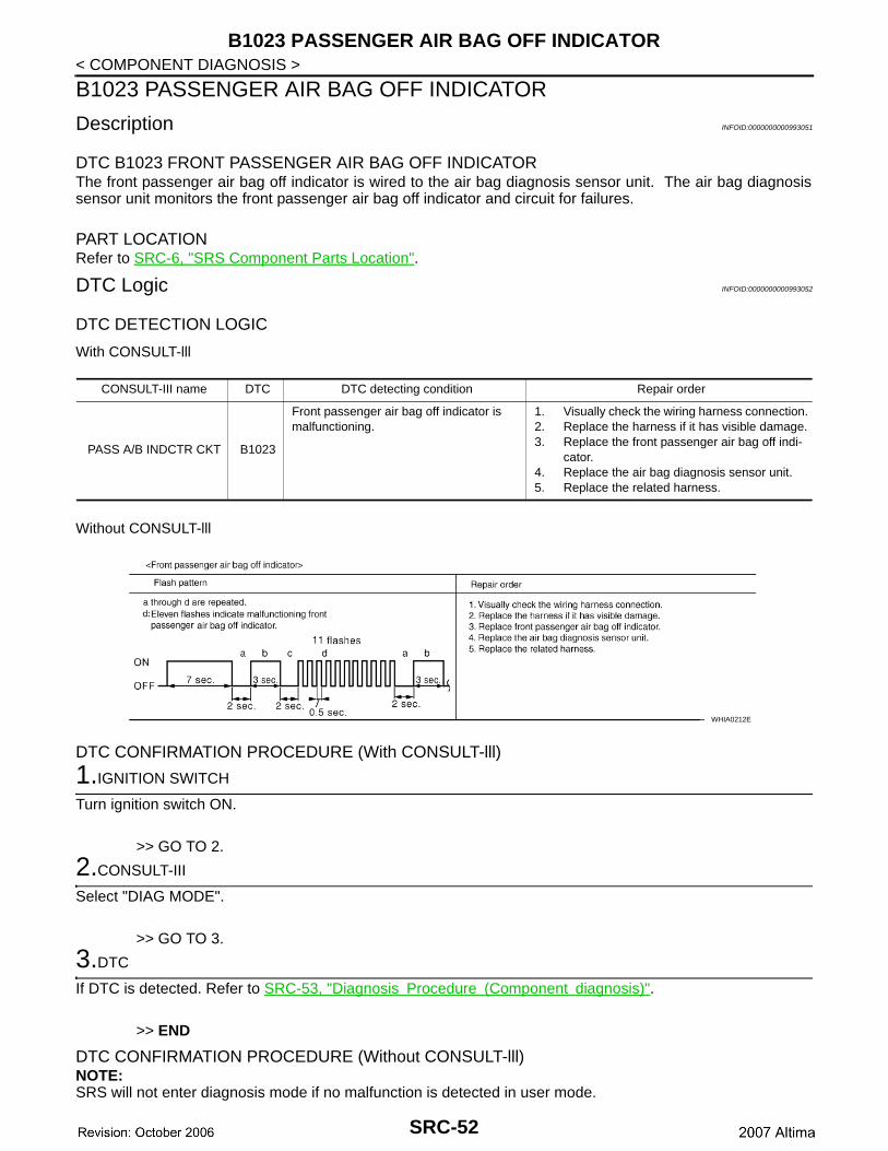
DTC B1023 FRONT PASSENGER AIR BAG OFF INDICATORThe front passenger air bag off indicator is wired to the air bag diagnosis sensor unit. The air bag diagnosissensor unit monitors the front passenger air bag off indicator and circuit for failures.
PART LOCATIONRefer to SRC-6, "SRS Component Parts Location".
DTC Logic INFOID:0000000000993052
DTC DETECTION LOGIC
With CONSULT-lll
Without CONSULT-lll
DTC CONFIRMATION PROCEDURE (With CONSULT-lll)
1.IGNITION SWITCH
Turn ignition switch ON.
>> GO TO 2.
2.CONSULT-III
Select "DIAG MODE".
>> GO TO 3.
3.DTC
If DTC is detected. Refer to SRC-53, "Diagnosis Procedure (Component diagnosis)".
>> END
DTC CONFIRMATION PROCEDURE (Without CONSULT-lll)NOTE:SRS will not enter diagnosis mode if no malfunction is detected in user mode.
CONSULT-III name DTC DTC detecting condition Repair order
PASS A/B INDCTR CKT B1023
Front passenger air bag off indicator is malfunctioning.
1. Visually check the wiring harness connection.2. Replace the harness if it has visible damage.3. Replace the front passenger air bag off indi-
cator.4. Replace the air bag diagnosis sensor unit.5. Replace the related harness.
WHIA0212E
SRC-52
B1023 PASSENGER AIR BAG OFF INDICATOR
C
D
E
F
G
I
J
K
L
M
A
B
RC
N
O
P
< COMPONENT DIAGNOSIS >
S
1.IGNITION SWITCH
Turn ignition switch ON.
>> GO TO 2..
2.IGNITION SWITCH
After air bag warning lamp lights for 7 seconds, turn ignition switch OFF within 1 second.
>> GO TO 3.
3.WAIT TIME
Wait more than 3 seconds.
>> GO TO 4.
4.REPEAT STEPS
Repeat steps 1 to 3 twice.
>> GO TO 5.
5.IGNITION SWITCH
Turn ignition switch ON.
>> GO TO 6.
6.DIAGNOSTIC MODE
SRS system is now in diagnostic mode and AIR BAG warning lamp flashes. Refer to SRC-70, "Trouble Diag-nosis without CONSULT-III".
>> END
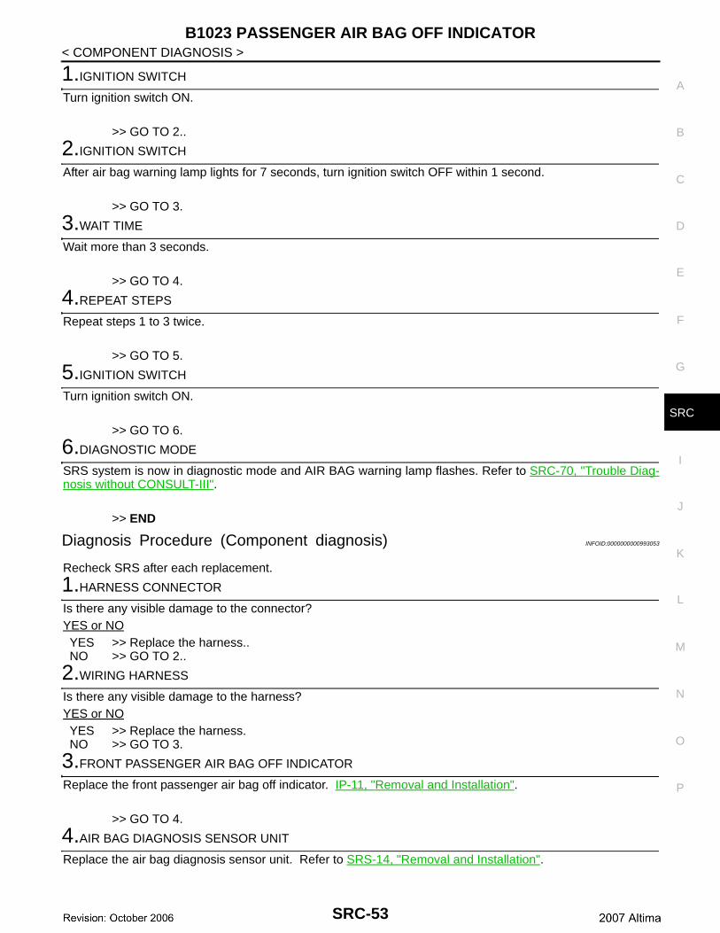
Diagnosis Procedure (Component diagnosis) INFOID:0000000000993053
Recheck SRS after each replacement.
1.HARNESS CONNECTOR
Is there any visible damage to the connector?YES or NOYES >> Replace the harness..NO >> GO TO 2..
2.WIRING HARNESS
Is there any visible damage to the harness?YES or NOYES >> Replace the harness.NO >> GO TO 3.
3.FRONT PASSENGER AIR BAG OFF INDICATOR
Replace the front passenger air bag off indicator. IP-11, "Removal and Installation".
>> GO TO 4.
4.AIR BAG DIAGNOSIS SENSOR UNIT
Replace the air bag diagnosis sensor unit. Refer to SRS-14, "Removal and Installation".
SRC-53
B1023 PASSENGER AIR BAG OFF INDICATOR
< COMPONENT DIAGNOSIS >>> GO TO 5.
5.RELATED HARNESS
Replace the related harness.
>> END
SRC-54
B1017, B1018, B1020 – B1022 OCCUPANT CLASSIFICATION SYSTEM
C
D
E
F
G
I
J
K
L
M
A
B
RC
N
O
P
< COMPONENT DIAGNOSIS >
S
B1017, B1018, B1020 – B1022 OCCUPANT CLASSIFICATION SYSTEM
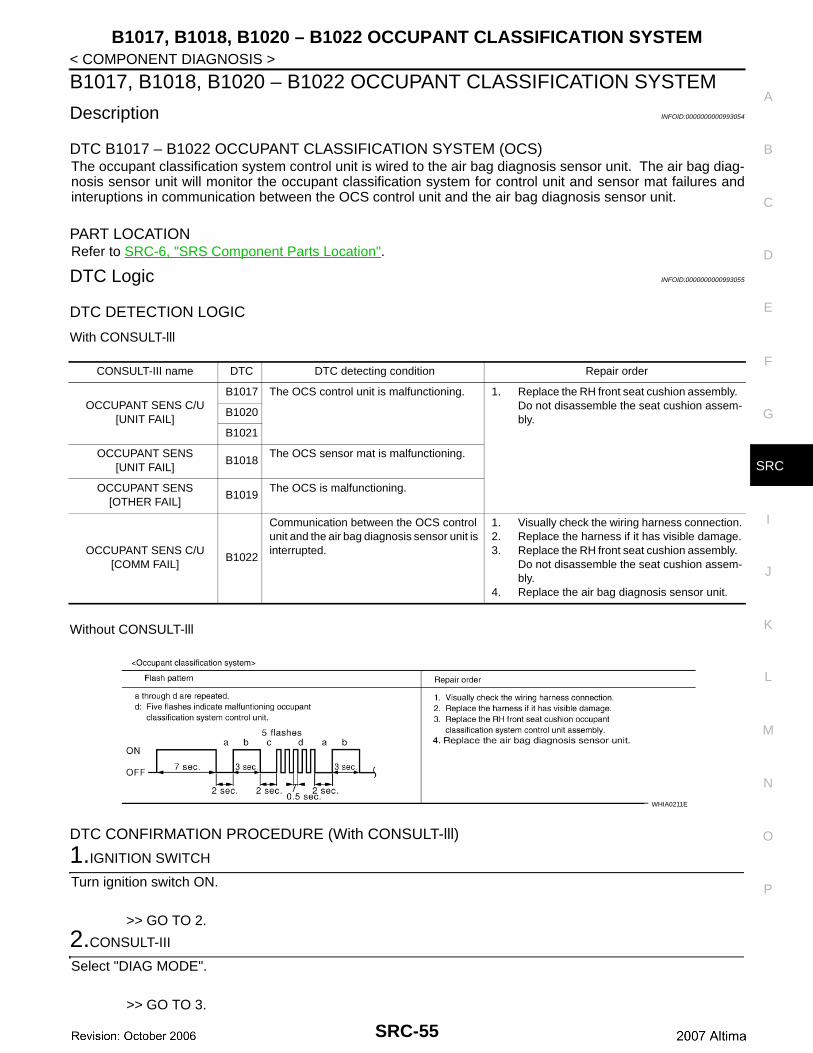
Description INFOID:0000000000993054
DTC B1017 – B1022 OCCUPANT CLASSIFICATION SYSTEM (OCS)The occupant classification system control unit is wired to the air bag diagnosis sensor unit. The air bag diag-nosis sensor unit will monitor the occupant classification system for control unit and sensor mat failures andinteruptions in communication between the OCS control unit and the air bag diagnosis sensor unit.
PART LOCATIONRefer to SRC-6, "SRS Component Parts Location".
DTC Logic INFOID:0000000000993055
DTC DETECTION LOGIC
With CONSULT-lll
Without CONSULT-lll
DTC CONFIRMATION PROCEDURE (With CONSULT-lll)
1.IGNITION SWITCH
Turn ignition switch ON.
>> GO TO 2.
2.CONSULT-III
Select "DIAG MODE".
>> GO TO 3.
CONSULT-III name DTC DTC detecting condition Repair order
OCCUPANT SENS C/U[UNIT FAIL]
B1017 The OCS control unit is malfunctioning. 1. Replace the RH front seat cushion assembly. Do not disassemble the seat cushion assem-bly.
B1020
B1021
OCCUPANT SENS[UNIT FAIL]
B1018The OCS sensor mat is malfunctioning.
OCCUPANT SENS[OTHER FAIL]
B1019The OCS is malfunctioning.
OCCUPANT SENS C/U[COMM FAIL]
B1022
Communication between the OCS control unit and the air bag diagnosis sensor unit is interrupted.
1. Visually check the wiring harness connection.2. Replace the harness if it has visible damage.3. Replace the RH front seat cushion assembly.
Do not disassemble the seat cushion assem-bly.
4. Replace the air bag diagnosis sensor unit.
WHIA0211E
SRC-55
B1017, B1018, B1020 – B1022 OCCUPANT CLASSIFICATION SYSTEM
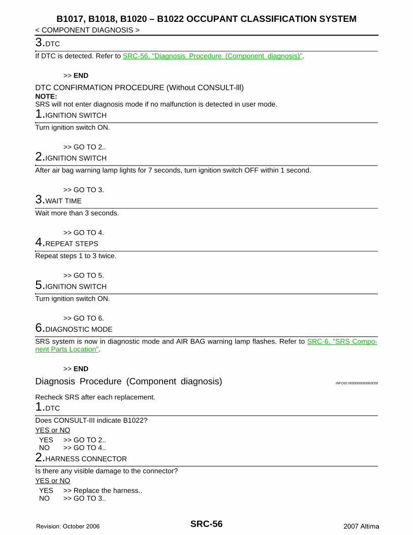
< COMPONENT DIAGNOSIS >3.DTC
If DTC is detected. Refer to SRC-56, "Diagnosis Procedure (Component diagnosis)".
>> END
DTC CONFIRMATION PROCEDURE (Without CONSULT-lll)NOTE:SRS will not enter diagnosis mode if no malfunction is detected in user mode.
1.IGNITION SWITCH
Turn ignition switch ON.
>> GO TO 2..
2.IGNITION SWITCH
After air bag warning lamp lights for 7 seconds, turn ignition switch OFF within 1 second.
>> GO TO 3.
3.WAIT TIME
Wait more than 3 seconds.
>> GO TO 4.
4.REPEAT STEPS
Repeat steps 1 to 3 twice.
>> GO TO 5.
5.IGNITION SWITCH
Turn ignition switch ON.
>> GO TO 6.
6.DIAGNOSTIC MODE
SRS system is now in diagnostic mode and AIR BAG warning lamp flashes. Refer to SRC-6, "SRS Compo-nent Parts Location".
>> END
Diagnosis Procedure (Component diagnosis) INFOID:0000000000993056
Recheck SRS after each replacement.
1.DTC
Does CONSULT-III indicate B1022?YES or NOYES >> GO TO 2..NO >> GO TO 4..
2.HARNESS CONNECTOR
Is there any visible damage to the connector?YES or NOYES >> Replace the harness..NO >> GO TO 3..
SRC-56
B1017, B1018, B1020 – B1022 OCCUPANT CLASSIFICATION SYSTEM
C
D
E
F
G
I
J
K
L
M
A
B
RC
N
O
P
< COMPONENT DIAGNOSIS >
S
3.WIRING HARNESS
Is there any visible damage to the harness?YES or NOYES >> Replace the harness.NO >> GO TO 4.
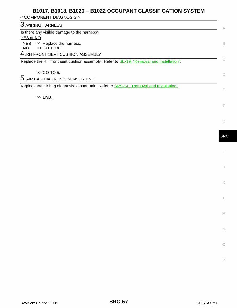
4.RH FRONT SEAT CUSHION ASSEMBLY
Replace the RH front seat cushion assembly. Refer to SE-19, "Removal and Installation".
>> GO TO 5.
5.AIR BAG DIAGNOSIS SENSOR UNIT
Replace the air bag diagnosis sensor unit. Refer to SRS-14, "Removal and Installation".
>> END.
SRC-57
B1209 – B1210 COLLISION DETECTION
< COMPONENT DIAGNOSIS >B1209 – B1210 COLLISION DETECTION
Description INFOID:0000000000993057
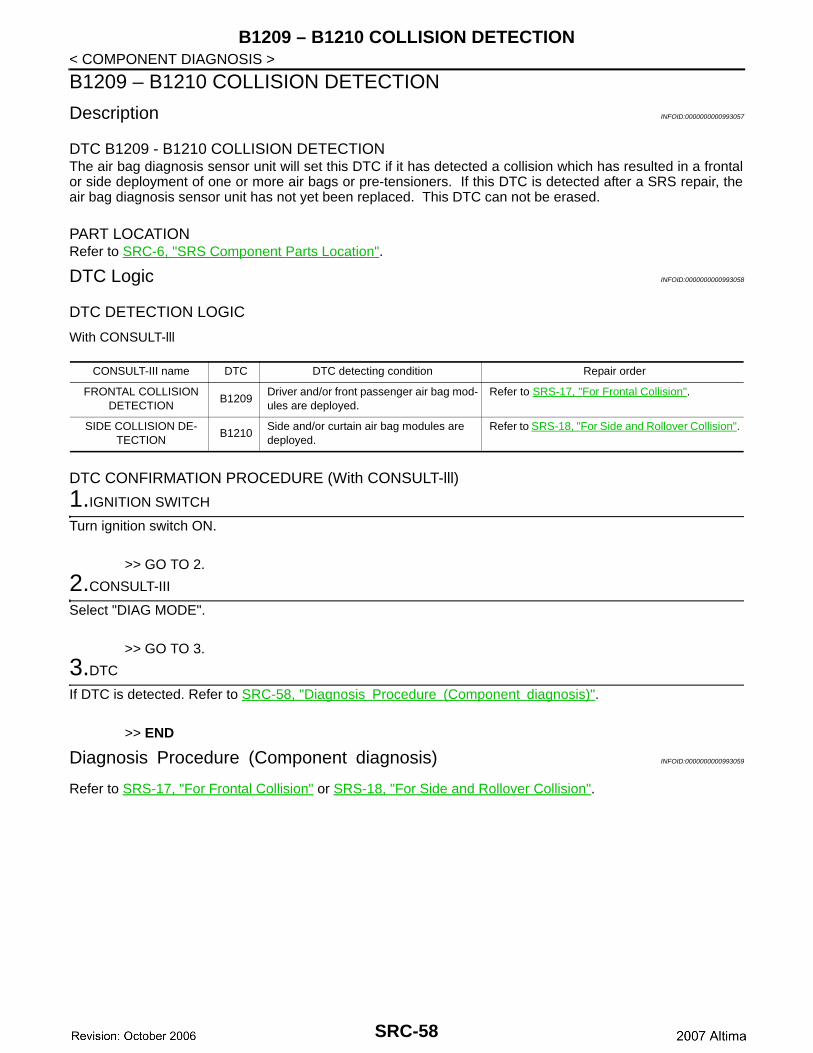
DTC B1209 - B1210 COLLISION DETECTIONThe air bag diagnosis sensor unit will set this DTC if it has detected a collision which has resulted in a frontalor side deployment of one or more air bags or pre-tensioners. If this DTC is detected after a SRS repair, theair bag diagnosis sensor unit has not yet been replaced. This DTC can not be erased.
PART LOCATIONRefer to SRC-6, "SRS Component Parts Location".
DTC Logic INFOID:0000000000993058
DTC DETECTION LOGIC
With CONSULT-lll
DTC CONFIRMATION PROCEDURE (With CONSULT-lll)
1.IGNITION SWITCH
Turn ignition switch ON.
>> GO TO 2.
2.CONSULT-III
Select "DIAG MODE".
>> GO TO 3.
3.DTC
If DTC is detected. Refer to SRC-58, "Diagnosis Procedure (Component diagnosis)".
>> END
Diagnosis Procedure (Component diagnosis) INFOID:0000000000993059
Refer to SRS-17, "For Frontal Collision" or SRS-18, "For Side and Rollover Collision".
CONSULT-III name DTC DTC detecting condition Repair order
FRONTAL COLLISION DETECTION
B1209Driver and/or front passenger air bag mod-ules are deployed.
Refer to SRS-17, "For Frontal Collision".
SIDE COLLISION DE-TECTION
B1210Side and/or curtain air bag modules are deployed.
Refer to SRS-18, "For Side and Rollover Collision".
SRC-58
DIAGNOSIS SENSOR UNIT
C
D
E
F
G
I
J
K
L
M
A
B
RC
N
O
P
< ECU DIAGNOSIS >
S
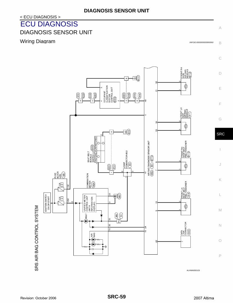
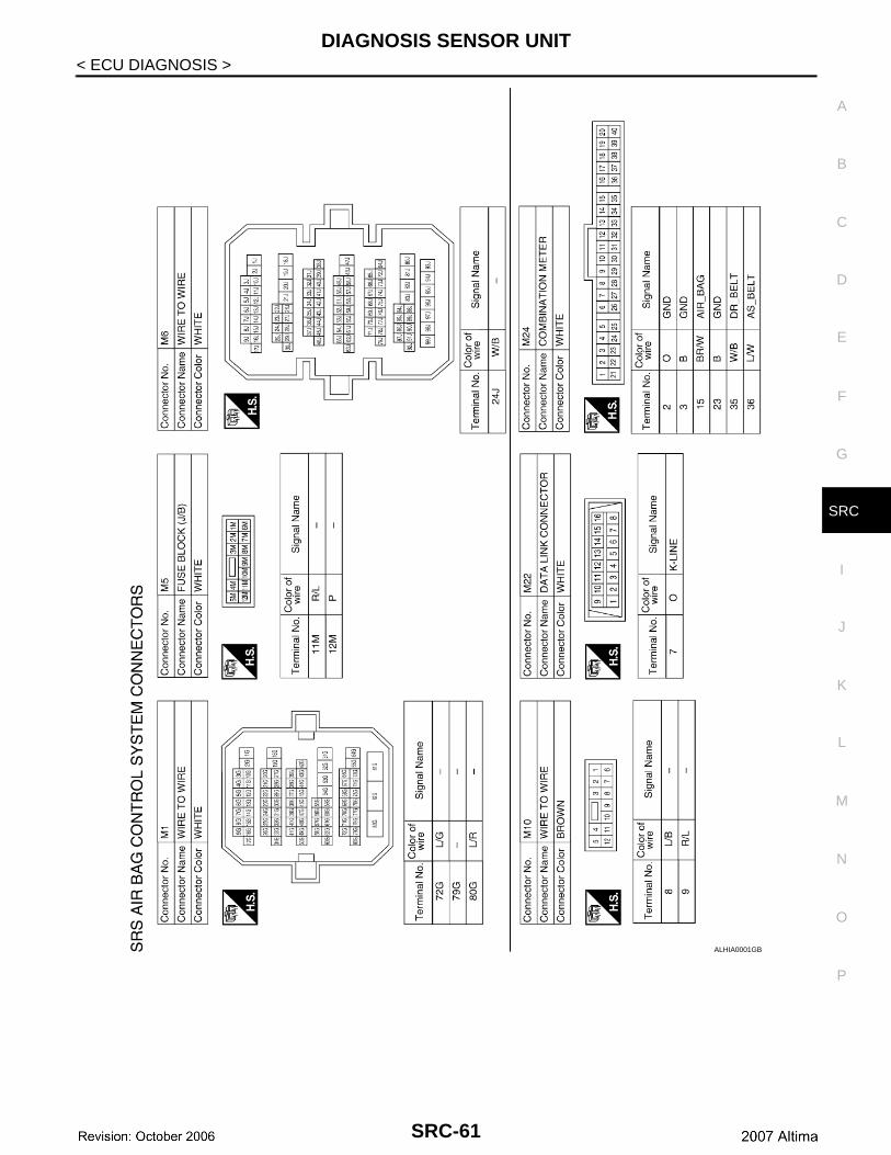
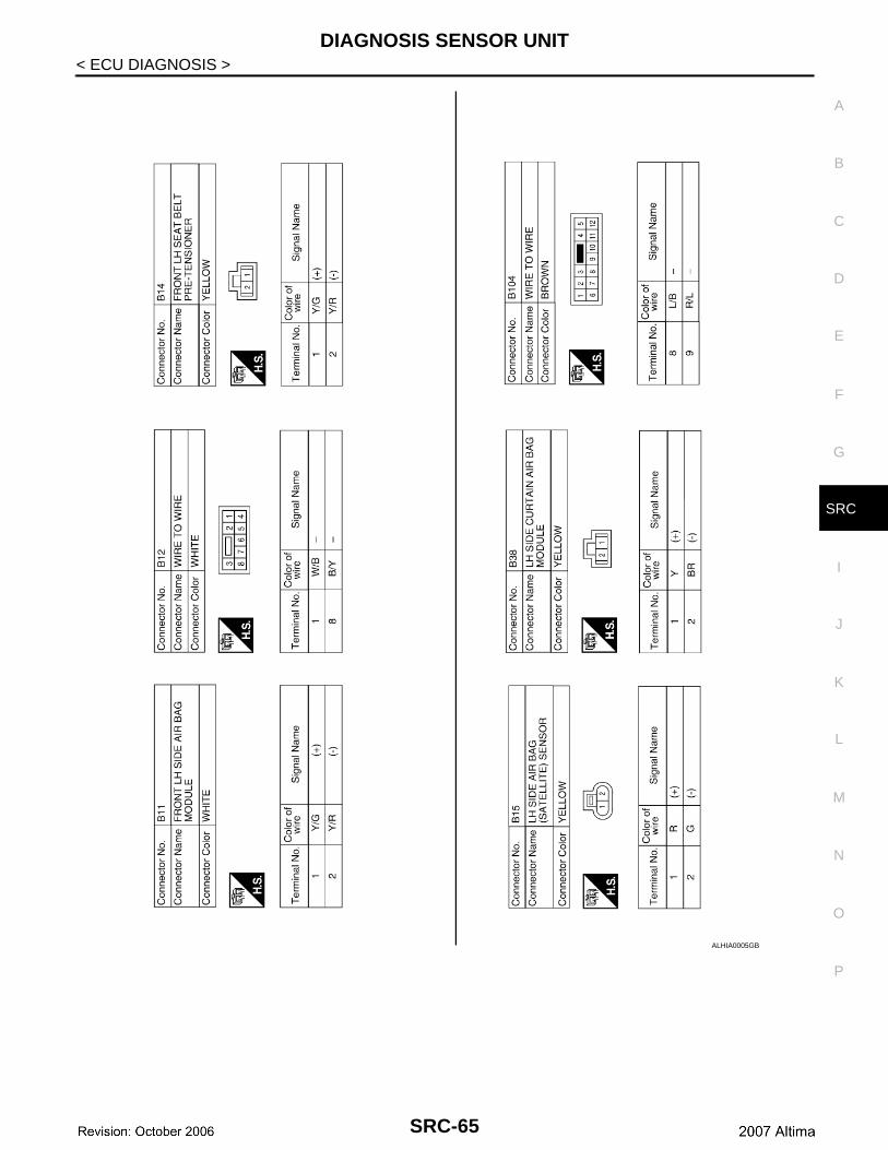
ECU DIAGNOSISDIAGNOSIS SENSOR UNIT
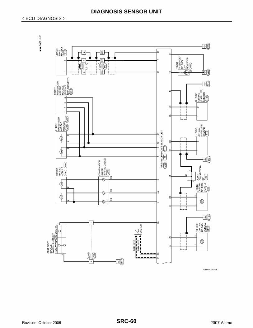
Wiring Diagram INFOID:0000000000993060
ALHWA0001GB
SRC-59
DIAGNOSIS SENSOR UNIT
< ECU DIAGNOSIS >ALHWA0002GB
SRC-60
DIAGNOSIS SENSOR UNIT
C
D
E
F
G
I
J
K
L
M
A
B
RC
N
O
P
< ECU DIAGNOSIS >
S
ALHIA0001GB
SRC-61
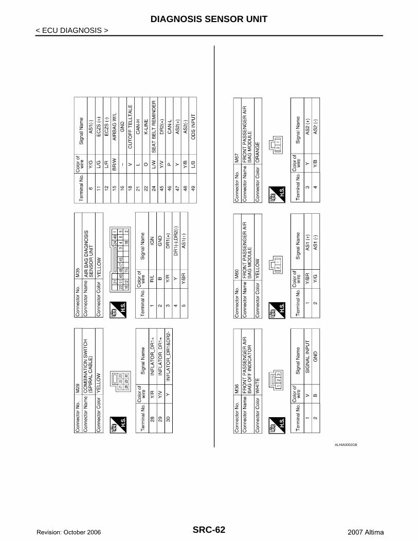
DIAGNOSIS SENSOR UNIT
< ECU DIAGNOSIS >ALHIA0002GB
SRC-62
DIAGNOSIS SENSOR UNIT
C
D
E
F
G
I
J
K
L
M
A
B
RC
N
O
P
< ECU DIAGNOSIS >
S
ALHIA0003GB
SRC-63
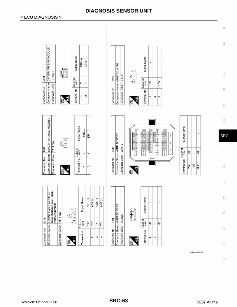
DIAGNOSIS SENSOR UNIT
< ECU DIAGNOSIS >ALHIA0004GB
SRC-64
DIAGNOSIS SENSOR UNIT
C
D
E
F
G
I
J
K
L
M
A
B
RC
N
O
P
< ECU DIAGNOSIS >
S
ALHIA0005GB
SRC-65
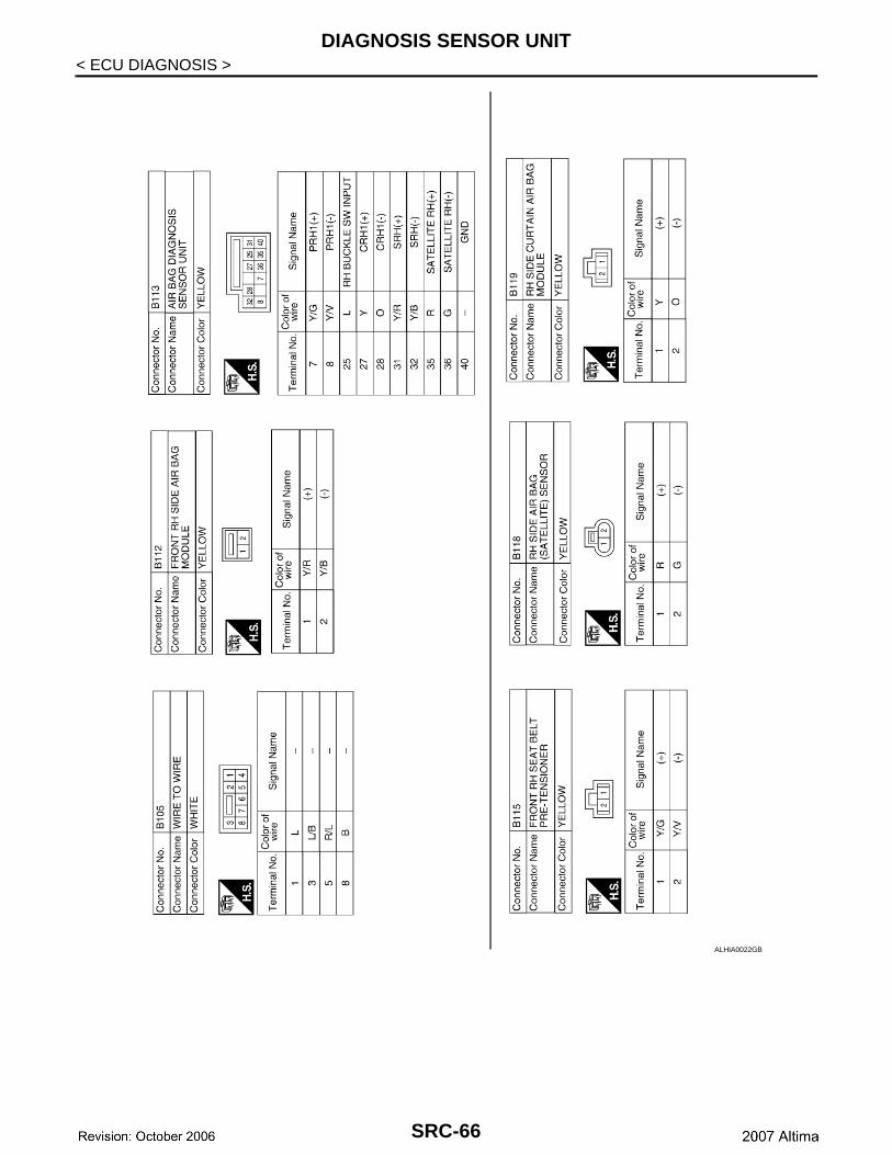
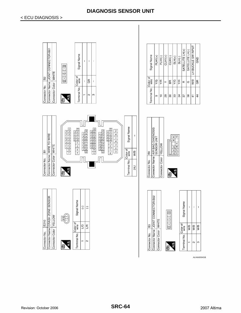
DIAGNOSIS SENSOR UNIT
< ECU DIAGNOSIS >ALHIA0022GB
SRC-66
DIAGNOSIS SENSOR UNIT
C
D
E
F
G
I
J
K
L
M
A
B
RC
N
O
P
< ECU DIAGNOSIS >
S
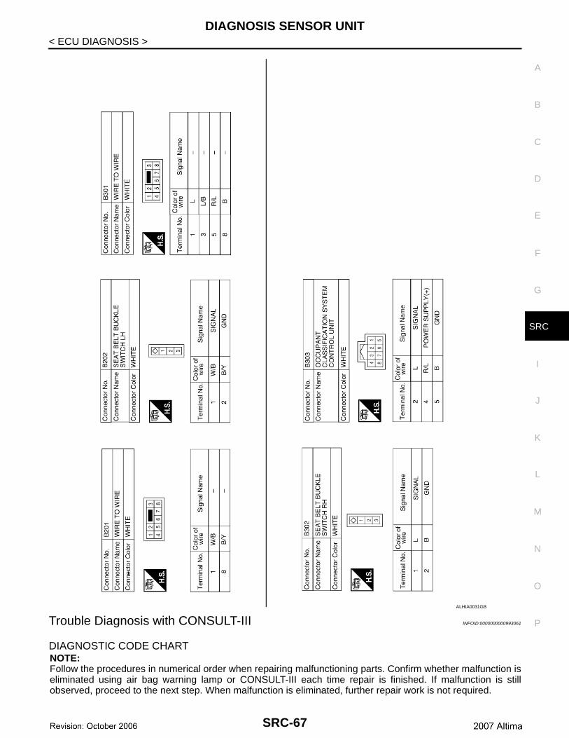
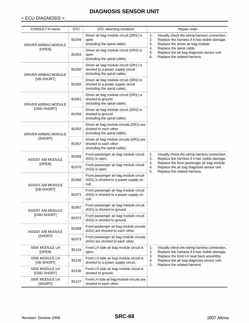
Trouble Diagnosis with CONSULT-III INFOID:0000000000993061
DIAGNOSTIC CODE CHARTNOTE:Follow the procedures in numerical order when repairing malfunctioning parts. Confirm whether malfunction iseliminated using air bag warning lamp or CONSULT-III each time repair is finished. If malfunction is stillobserved, proceed to the next step. When malfunction is eliminated, further repair work is not required.
ALHIA0031GB
SRC-67
DIAGNOSIS SENSOR UNIT
< ECU DIAGNOSIS >CONSULT-III name DTC DTC detecting condition Repair order
DRIVER AIRBAG MODULE [OPEN]
B1049Driver air bag module circuit (DR1) is open(including the spiral cable).
1. Visually check the wiring harness connection.2. Replace the harness if it has visible damage.3. Replace the driver air bag module.4. Replace the spiral cable.5. Replace the air bag diagnosis sensor unit.6. Replace the related harness.
B1054Driver air bag module circuit (DR2) is open(including the spiral cable).
DRIVER AIRBAG MODULE [VB-SHORT]
B1050Driver air bag module circuit (DR1) is shorted to a power supply circuit(including the spiral cable).
B1055Driver air bag module circuit (DR2) is shorted to a power supply circuit(including the spiral cable).
DRIVER AIRBAG MODULE [GND-SHORT]
B1051Driver air bag module circuit (DR1) is shorted to ground(including the spiral cable).
B1056Driver air bag module circuit (DR2) is shorted to ground(including the spiral cable).
DRIVER AIRBAG MODULE [SHORT]
B1052Driver air bag module circuits (DR1) are shorted to each other(including the spiral cable).
B1057Driver air bag module circuits (DR2) are shorted to each other(including the spiral cable).
ASSIST A/B MODULE [OPEN]
B1065Front passenger air bag module circuit (AS1) is open.
1. Visually check the wiring harness connection.2. Replace the harness if it has visible damage.3. Replace the front passenger air bag module.4. Replace the air bag diagnosis sensor unit.5. Replace the related harness.
B1070Front passenger air bag module circuit (AS2) is open.
ASSIST A/B MODULE [VB-SHORT]
B1066Front passenger air bag module circuit (AS1) is shorted to a power supply cir-cuit.
B1071Front passenger air bag module circuit (AS2) is shorted to a power supply cir-cuit.
ASSIST A/B MODULE [GND-SHORT]
B1067Front passenger air bag module circuit (AS1) is shorted to ground.
B1072Front passenger air bag module circuit (AS2) is shorted to ground.
ASSIST A/B MODULE [SHORT]
B1068Front passenger air bag module circuits (AS1) are shorted to each other.
B1073Front passenger air bag module circuits (AS2) are shorted to each other.
SIDE MODULE LH [OPEN]
B1134Front LH side air bag module circuit is open.
1. Visually check the wiring harness connection.2. Replace the harness if it has visible damage.3. Replace the front LH seat back assembly.4. Replace the air bag diagnosis sensor unit.5. Replace the related harness.
SIDE MODULE LH [VB-SHORT]
B1135Front LH side air bag module circuit is shorted to a power supply circuit.
SIDE MODULE LH [GND-SHORT]
B1136Front LH side air bag module circuit is shorted to ground.
SIDE MODULE LH [SHORT]
B1137Front LH side air bag module circuits are shorted to each other.
SRC-68
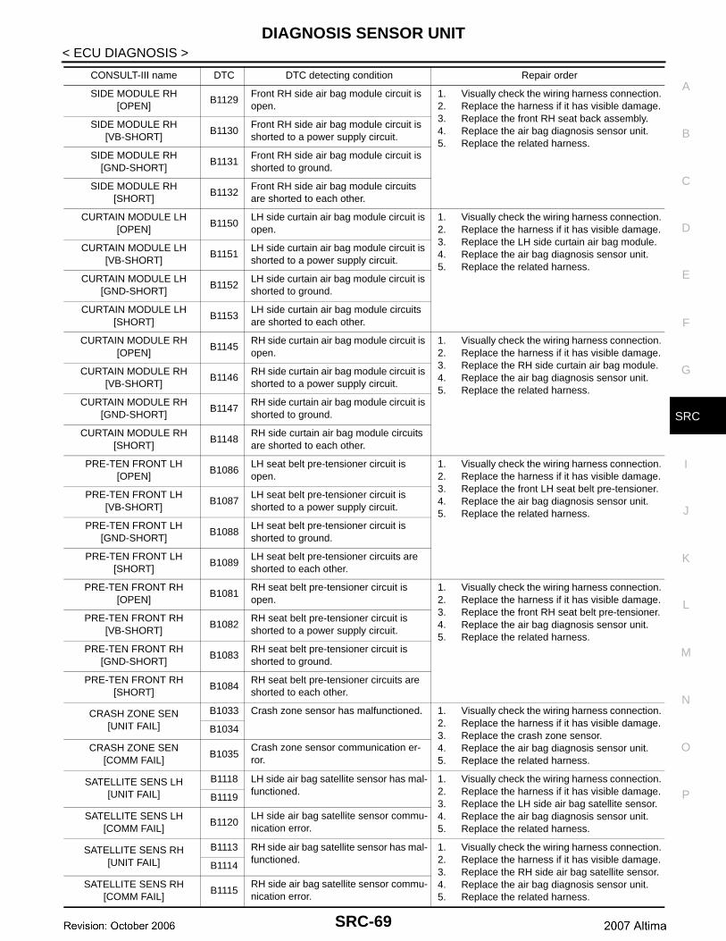
DIAGNOSIS SENSOR UNIT
C
D
E
F
G
I
J
K
L
M
A
B
RC
N
O
P
< ECU DIAGNOSIS >
S
SIDE MODULE RH [OPEN]
B1129Front RH side air bag module circuit is open.
1. Visually check the wiring harness connection.2. Replace the harness if it has visible damage.3. Replace the front RH seat back assembly.4. Replace the air bag diagnosis sensor unit.5. Replace the related harness.
SIDE MODULE RH [VB-SHORT]
B1130Front RH side air bag module circuit is shorted to a power supply circuit.
SIDE MODULE RH [GND-SHORT]
B1131Front RH side air bag module circuit is shorted to ground.
SIDE MODULE RH [SHORT]
B1132Front RH side air bag module circuits are shorted to each other.
CURTAIN MODULE LH [OPEN]
B1150LH side curtain air bag module circuit is open.
1. Visually check the wiring harness connection.2. Replace the harness if it has visible damage.3. Replace the LH side curtain air bag module.4. Replace the air bag diagnosis sensor unit.5. Replace the related harness.
CURTAIN MODULE LH [VB-SHORT]
B1151LH side curtain air bag module circuit is shorted to a power supply circuit.
CURTAIN MODULE LH [GND-SHORT]
B1152LH side curtain air bag module circuit is shorted to ground.
CURTAIN MODULE LH [SHORT]
B1153LH side curtain air bag module circuits are shorted to each other.
CURTAIN MODULE RH [OPEN]
B1145RH side curtain air bag module circuit is open.
1. Visually check the wiring harness connection.2. Replace the harness if it has visible damage.3. Replace the RH side curtain air bag module.4. Replace the air bag diagnosis sensor unit.5. Replace the related harness.
CURTAIN MODULE RH [VB-SHORT]
B1146RH side curtain air bag module circuit is shorted to a power supply circuit.
CURTAIN MODULE RH [GND-SHORT]
B1147RH side curtain air bag module circuit is shorted to ground.
CURTAIN MODULE RH [SHORT]
B1148RH side curtain air bag module circuits are shorted to each other.
PRE-TEN FRONT LH [OPEN]
B1086LH seat belt pre-tensioner circuit is open.
1. Visually check the wiring harness connection.2. Replace the harness if it has visible damage.3. Replace the front LH seat belt pre-tensioner.4. Replace the air bag diagnosis sensor unit.5. Replace the related harness.
PRE-TEN FRONT LH [VB-SHORT]
B1087LH seat belt pre-tensioner circuit is shorted to a power supply circuit.
PRE-TEN FRONT LH [GND-SHORT]
B1088LH seat belt pre-tensioner circuit is shorted to ground.
PRE-TEN FRONT LH [SHORT]
B1089LH seat belt pre-tensioner circuits are shorted to each other.
PRE-TEN FRONT RH [OPEN]
B1081RH seat belt pre-tensioner circuit is open.
1. Visually check the wiring harness connection.2. Replace the harness if it has visible damage.3. Replace the front RH seat belt pre-tensioner.4. Replace the air bag diagnosis sensor unit.5. Replace the related harness.
PRE-TEN FRONT RH [VB-SHORT]
B1082RH seat belt pre-tensioner circuit is shorted to a power supply circuit.
PRE-TEN FRONT RH [GND-SHORT]
B1083RH seat belt pre-tensioner circuit is shorted to ground.
PRE-TEN FRONT RH [SHORT]
B1084RH seat belt pre-tensioner circuits are shorted to each other.
CRASH ZONE SEN[UNIT FAIL]
B1033 Crash zone sensor has malfunctioned. 1. Visually check the wiring harness connection.2. Replace the harness if it has visible damage.3. Replace the crash zone sensor.4. Replace the air bag diagnosis sensor unit.5. Replace the related harness.
B1034
CRASH ZONE SEN[COMM FAIL]
B1035Crash zone sensor communication er-ror.
SATELLITE SENS LH[UNIT FAIL]
B1118 LH side air bag satellite sensor has mal-functioned.
1. Visually check the wiring harness connection.2. Replace the harness if it has visible damage.3. Replace the LH side air bag satellite sensor.4. Replace the air bag diagnosis sensor unit.5. Replace the related harness.
B1119
SATELLITE SENS LH[COMM FAIL]
B1120LH side air bag satellite sensor commu-nication error.
SATELLITE SENS RH[UNIT FAIL]
B1113 RH side air bag satellite sensor has mal-functioned.
1. Visually check the wiring harness connection.2. Replace the harness if it has visible damage.3. Replace the RH side air bag satellite sensor.4. Replace the air bag diagnosis sensor unit.5. Replace the related harness.
B1114
SATELLITE SENS RH[COMM FAIL]
B1115RH side air bag satellite sensor commu-nication error.
CONSULT-III name DTC DTC detecting condition Repair order
SRC-69
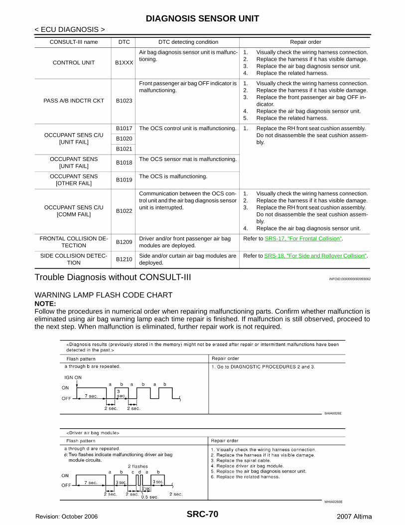
DIAGNOSIS SENSOR UNIT
< ECU DIAGNOSIS >Trouble Diagnosis without CONSULT-III INFOID:0000000000993062
WARNING LAMP FLASH CODE CHARTNOTE:Follow the procedures in numerical order when repairing malfunctioning parts. Confirm whether malfunction iseliminated using air bag warning lamp each time repair is finished. If malfunction is still observed, proceed tothe next step. When malfunction is eliminated, further repair work is not required.
CONTROL UNIT B1XXX
Air bag diagnosis sensor unit is malfunc-tioning.
1. Visually check the wiring harness connection.2. Replace the harness if it has visible damage.3. Replace the air bag diagnosis sensor unit.4. Replace the related harness.
PASS A/B INDCTR CKT B1023
Front passenger air bag OFF indicator is malfunctioning.
1. Visually check the wiring harness connection.2. Replace the harness if it has visible damage.3. Replace the front passenger air bag OFF in-
dicator.4. Replace the air bag diagnosis sensor unit.5. Replace the related harness.
OCCUPANT SENS C/U[UNIT FAIL]
B1017 The OCS control unit is malfunctioning. 1. Replace the RH front seat cushion assembly. Do not disassemble the seat cushion assem-bly.
B1020
B1021
OCCUPANT SENS[UNIT FAIL]
B1018The OCS sensor mat is malfunctioning.
OCCUPANT SENS[OTHER FAIL]
B1019The OCS is malfunctioning.
OCCUPANT SENS C/U[COMM FAIL]
B1022
Communication between the OCS con-trol unit and the air bag diagnosis sensor unit is interrupted.
1. Visually check the wiring harness connection.2. Replace the harness if it has visible damage.3. Replace the RH front seat cushion assembly.
Do not disassemble the seat cushion assem-bly.
4. Replace the air bag diagnosis sensor unit.
FRONTAL COLLISION DE-TECTION
B1209Driver and/or front passenger air bag modules are deployed.
Refer to SRS-17, "For Frontal Collision".
SIDE COLLISION DETEC-TION
B1210Side and/or curtain air bag modules are deployed.
Refer to SRS-18, "For Side and Rollover Collision".
CONSULT-III name DTC DTC detecting condition Repair order
SHIA0026E
WHIA0260E
SRC-70
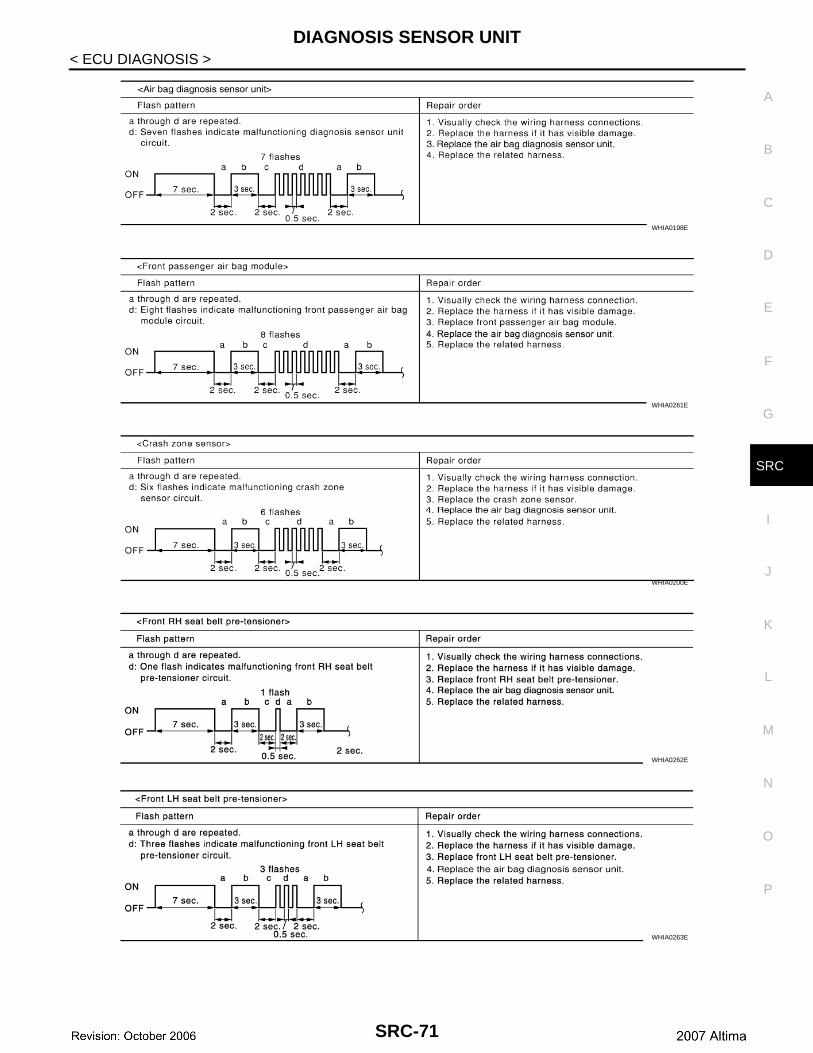
DIAGNOSIS SENSOR UNIT
C
D
E
F
G
I
J
K
L
M
A
B
RC
N
O
P
< ECU DIAGNOSIS >
S
WHIA0198E
WHIA0261E
WHIA0200E
WHIA0262E
WHIA0263E
SRC-71
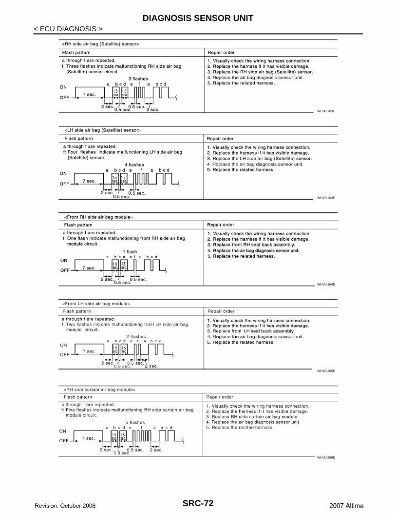
DIAGNOSIS SENSOR UNIT
< ECU DIAGNOSIS >WHIA0203E
WHIA0204E
WHIA0264E
WHIA0265E
WHIA0266E
SRC-72
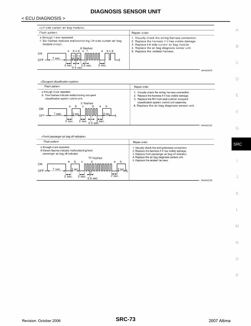
DIAGNOSIS SENSOR UNIT
C
D
E
F
G
I
J
K
L
M
A
B
RC
N
O
P
< ECU DIAGNOSIS >
S
WHIA0267E
WHIA0211E
WHIA0212E
SRC-73
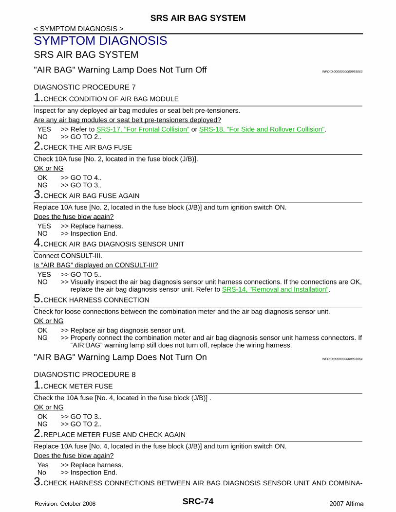
SRS AIR BAG SYSTEM
< SYMPTOM DIAGNOSIS >SYMPTOM DIAGNOSISSRS AIR BAG SYSTEM
"AIR BAG" Warning Lamp Does Not Turn Off INFOID:0000000000993063
DIAGNOSTIC PROCEDURE 7
1.CHECK CONDITION OF AIR BAG MODULE
Inspect for any deployed air bag modules or seat belt pre-tensioners.Are any air bag modules or seat belt pre-tensioners deployed?YES >> Refer to SRS-17, "For Frontal Collision" or SRS-18, "For Side and Rollover Collision".NO >> GO TO 2..
2.CHECK THE AIR BAG FUSE
Check 10A fuse [No. 2, located in the fuse block (J/B)].OK or NGOK >> GO TO 4..NG >> GO TO 3..
3.CHECK AIR BAG FUSE AGAIN
Replace 10A fuse [No. 2, located in the fuse block (J/B)] and turn ignition switch ON.Does the fuse blow again?YES >> Replace harness.NO >> Inspection End.
4.CHECK AIR BAG DIAGNOSIS SENSOR UNIT
Connect CONSULT-III.Is “AIR BAG” displayed on CONSULT-III?YES >> GO TO 5..NO >> Visually inspect the air bag diagnosis sensor unit harness connections. If the connections are OK,
replace the air bag diagnosis sensor unit. Refer to SRS-14, "Removal and Installation".
5.CHECK HARNESS CONNECTION
Check for loose connections between the combination meter and the air bag diagnosis sensor unit.OK or NGOK >> Replace air bag diagnosis sensor unit.NG >> Properly connect the combination meter and air bag diagnosis sensor unit harness connectors. If
“AIR BAG” warning lamp still does not turn off, replace the wiring harness.
"AIR BAG" Warning Lamp Does Not Turn On INFOID:0000000000993064
DIAGNOSTIC PROCEDURE 8
1.CHECK METER FUSE
Check the 10A fuse [No. 4, located in the fuse block (J/B)] .OK or NGOK >> GO TO 3..NG >> GO TO 2..
2.REPLACE METER FUSE AND CHECK AGAIN
Replace 10A fuse [No. 4, located in the fuse block (J/B)] and turn ignition switch ON.Does the fuse blow again?Yes >> Replace harness.No >> Inspection End.
3.CHECK HARNESS CONNECTIONS BETWEEN AIR BAG DIAGNOSIS SENSOR UNIT AND COMBINA-
SRC-74
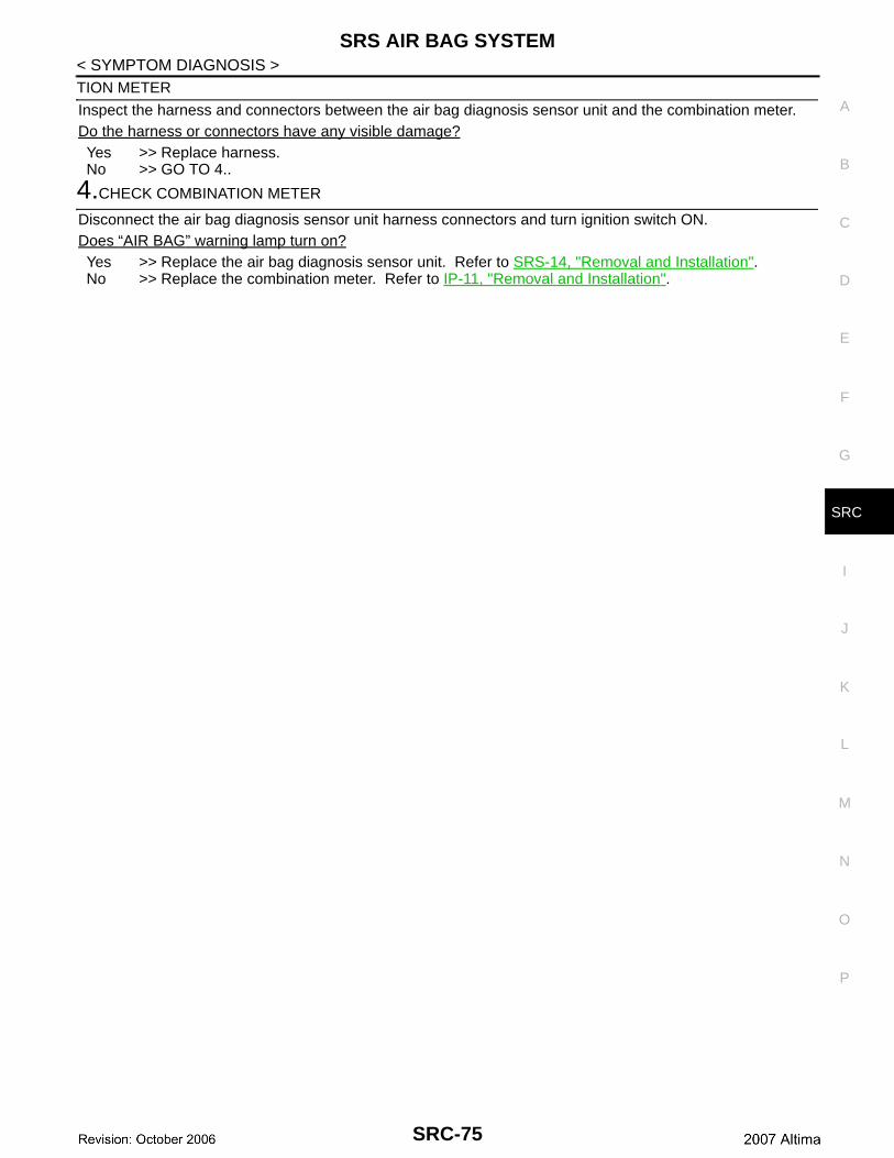
SRS AIR BAG SYSTEM
C
D
E
F
G
I
J
K
L
M
A
B
RC
N
O
P
< SYMPTOM DIAGNOSIS >
S
TION METER
Inspect the harness and connectors between the air bag diagnosis sensor unit and the combination meter.Do the harness or connectors have any visible damage?Yes >> Replace harness.No >> GO TO 4..
4.CHECK COMBINATION METER
Disconnect the air bag diagnosis sensor unit harness connectors and turn ignition switch ON.Does “AIR BAG” warning lamp turn on?Yes >> Replace the air bag diagnosis sensor unit. Refer to SRS-14, "Removal and Installation".No >> Replace the combination meter. Refer to IP-11, "Removal and Installation".
SRC-75
PASSENGER SEAT BELT WARNING SYSTEM
< SYMPTOM DIAGNOSIS >PASSENGER SEAT BELT WARNING SYSTEM
Seat Belt Warning System Does Not Function INFOID:0000000000993065
1.SEAT BELT WARNING LIGHT
Turn ignition switch ON.Does the seat belt warning lamp come ON?YES >> Go to 2.NO >> • Check 10A fuse [No. 4, located in the fuse block (J/B)].
• Check seat belt buckle switch LH.• Check harness between combination meter and seat belt buckle switch LH.• Check combination meter. Refer to MWI-47, "Fail Safe".
2.SEAT BELT BUCKLE LH
Fasten the seat belt buckle LH.Does the seat belt warning lamp go OFF?YES >> Go to 3.NO >> • Check seat belt buckle switch LH.
• Check harness between combination meter and seat belt buckle switch LH.
3.OCCUPANT CLASSIFICATION SYSTEM
Have a helper sit in the passenger seat.Does the seat belt warning lamp go ON?YES >> Go to 4.NO >> • Check occupant classification system. Refer to SRC-10, "Occupant Classification System
(OCS)".• Check harness between occupant classification control unit and air bag diagnosis sensor unit.
4.SEAT BELT BUCKLE RH
Fasten the seat belt buckle RH.Does the seat belt warning lamp go OFF?YES >> System OK.NO >> • Check seat belt buckle switch RH.
• Check harness between seat belt buckle switch RH and air bag diagnosis sensor unit.• Replace air bag diagnosis sensor unit. Refer to SRS-14, "Removal and Installation".
SRC-76
PRECAUTIONS
C
D
E
F
G
I
J
K
L
M
A
B
RC
N
O
P
< PRECAUTION >
S
PRECAUTIONPRECAUTIONS
Precaution for Supplemental Restraint System (SRS) "AIR BAG" and "SEAT BELT PRE-TENSIONER" INFOID:0000000000993066
The Supplemental Restraint System such as “AIR BAG” and “SEAT BELT PRE-TENSIONER”, used alongwith a front seat belt, helps to reduce the risk or severity of injury to the driver and front passenger for certaintypes of collision. This system includes seat belt switch inputs and dual stage front air bag modules. The SRSsystem uses the seat belt switches to determine the front air bag deployment, and may only deploy one frontair bag, depending on the severity of a collision and whether the front occupants are belted or unbelted.Information necessary to service the system safely is included in the SRS and SB section of this Service Man-ual.WARNING:• To avoid rendering the SRS inoperative, which could increase the risk of personal injury or death in
the event of a collision which would result in air bag inflation, all maintenance must be performed byan authorized NISSAN/INFINITI dealer.
• Improper maintenance, including incorrect removal and installation of the SRS, can lead to personalinjury caused by unintentional activation of the system. For removal of Spiral Cable and Air BagModule, see the SRS section.
• Do not use electrical test equipment on any circuit related to the SRS unless instructed to in thisService Manual. SRS wiring harnesses can be identified by yellow and/or orange harnesses or har-ness connectors.
Precaution for SRS "AIR BAG" and "SEAT BELT PRE-TENSIONER" ServiceINFOID:0000000000993067
• Do not use electrical test equipment to check SRS circuits unless instructed to in this Service Manual.• Before servicing the SRS, turn ignition switch OFF, disconnect both battery cables and wait at least 3 min-
utes.For approximately 3 minutes after the cables are removed, it is still possible for the air bag and seat belt pre-tensioner to deploy. Therefore, do not work on any SRS connectors or wires until at least 3 minutes havepassed.
• The air bag diagnosis sensor unit must always be installed with the arrow mark “⇐” pointing toward the frontof the vehicle for proper operation. Also check air bag diagnosis sensor unit for cracks, deformities or rustbefore installation and replace as required.
• The spiral cable must be aligned with the neutral position since its rotations are limited. Do not attempt toturn steering wheel or column after removal of steering gear.
• Handle air bag module carefully. Always place driver and front passenger air bag modules with the pad sidefacing upward and seat mounted front side air bag module standing with the stud bolt side facing down.
• Conduct self-diagnosis to check entire SRS for proper function after replacing any components.• After air bag inflates, the front instrument panel assembly should be replaced if damaged.
Occupant Classification System Precaution INFOID:0000000000993068
Replace occupant classification system control unit and passenger front seat cushion as an assembly.
SRC-77