Embed Size (px)
Citation preview
Retaining walls execution using the big
rectangular technique: the Brazilian experience Sérgio M. P. Velloso Filho & Eduardo Chahud Universidade FUMEC, Belo Horizonte, Minas Gerais, Brazil Lúcio Flávio Souza Villar Universidade Federal de Minas Gerais, Belo Horizonte, Minas Gerais, Brazil ABSTRACT With urban growth all around the world, it is observed a demand for big constructions with large excavations, such as subways, tunnels and underground garages. The real estate valuation in urban areas influences the architectural style and creates the need of executing underground basements until the boundary of the properties. Due to interferences and limitations imposed by neighboring constructions, executive retaining processes become important for its appropriated performance. Thus, in big cities, it is necessary to find construction methods alternatives which have in its conception some competitive advantage over others. The aim of this work is to present and standardize an execution method of retaining walls, the rectangular hand excavated shaft, popularly called "big rectangular", which was first used in the city of Belo Horizonte, in Minas Gerais, Brazil, and that is now applied all over the country. PRESENTACIONES TECNICAS Con el crecimiento urbano en todo el mundo, se observa una demanda de grandes construcciones con grandes excavaciones, tales como el metro, túneles y garajes subterráneas. La valoración de bienes inmuebles en las zonas urbanas influye en el estilo arquitectónico y crea la necesidad de la ejecución de basis subterráneas hasta el límite de las propiedades. Debido a las interferencias y limitaciones impuestas por las construcciones vecinas, los procesos ejecutivos de contención se hacen importantes para su el rendimiento apropiado. De esa manera, en las grandes ciudades, es necesario buscar alternativas de métodos de construcción que tienen en su concepción alguna ventaja competitiva sobre los demás. El objetivo de este trabajo es el de presentar y estandarizar un método de ejecución de muros de contención, la mano rectangular excavada basis, popularmente llamados "grande rectangular", que fue utilizado por primera vez en la ciudad de Belo Horizonte, en Minas Gerais, Brazil, y que ahora se aplica por todo el país. 1 INTRODUCTION The search for new techniques or methods which allow the execution of technically feasible jobs, more safely, and that provide some advantage over other existing ones is a constant objective in the technical environment. Saes et al (1998) point out that, in a containment job designing process, the condition to consider an alternative viable to solve a problem is that one which presents any competitive advantage over others.
In order to design containment's jobs, it must meet some conditions such as geological and geotechnical, geometric, topographic, business, economic and regional (Marzionna 1996).
Often, technologies developed in specific regions that satisfactorily meet these conditions become common practice, though they are unknown outside the places where they were developed. This is the case of containment implemented through concrete elements called big rectangular containment.
This technique has emerged in the city of Belo Horizonte, Brazil. Belo Horizonte is the capital of Minas Gerais State and its metropolitan area has over 4.5 million inhabitants. The city has in a large part of its length topography consisted of hills and valleys which buildings, not in rare cases, are built on hillside sites where access for equipment is difficult. Thus, despite the technological development increasingly pressing towards mechanized equipment, regional topographic condition
leads to use hand excavated shaft foundations and big rectangular retaining walls.
By changing the code jobs in the city, tall buildings occupy the entire area of the lots, until the border of the neighboring lots. For construction of basements in those neighboring parcels, it is necessary to run containments that serve to contain and underpinning the old buildings (executive constraint). Big rectangular is commonly used in these cases.
In order to increase the use of underground areas, projects are developed considering, each time more; the diminishing thickness for retaining walls and containing solution must be developed considering this premise design (geometric constraint). In these cases, big rectangular walls may have its cross section reduced, what allows them to be used.
From the perspective of reinforced concrete, the solution in big rectangular may, in several cases, become economical because of the steel area required compared to containments that use circular section (economic condition), once that the cross section is rectangular.
Ultimately, use of containments constituted by big rectangular arose intuitively in the late 1980's and early 1990's as a natural alternative, based on experience by routine use of dug opened foundations (regional constraint). To explain this method, Velloso Filho (2009) presents a systemized technique throughout the analysis of 289 cases of jobs using big rectangular.
2 CONTAINMENT METHOD USING BIG
RECTANGULAR TECHNIQUE
Big rectangular containment method is similar to cantilever wall that can possibly be sustained through both tiebacks and the structure itself, in case of basements.
Big rectangular is executed before the cut of the land in a not juxtaposed manner configuring a discontinuous containment. The spacing from face to face of these elements varies, according to the design project, from 0.5 m to 2.0 m. After cutting the site, these spaces, between big rectangular walls are provided by reinforced concrete or concrete blocks additional curtains.
As big rectangular usually presents rectangular cross sections from 0.5 m to 0.7 m width and 1.0 m to 1.1 m in length, it may be eventually equipped with bases which differ from sheet-piles walls for having non-negligible weight.
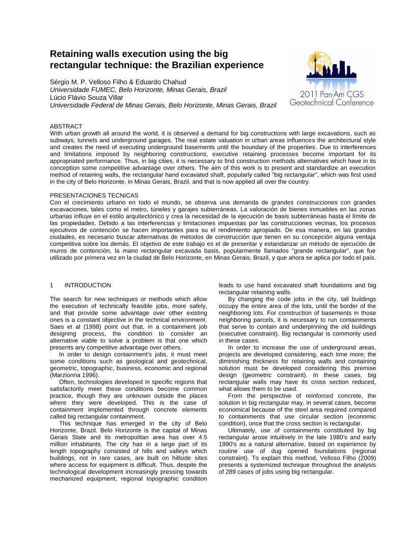
In Figure 1, it´s showed a typical cantilever big rectangular retaining wall.
Figure 1. View of a big rectangular retaining wall underpinning a gravity retaining wall (Unesco Museum – Congonhas, Brazil).
The use of the method is restricted to soils that have
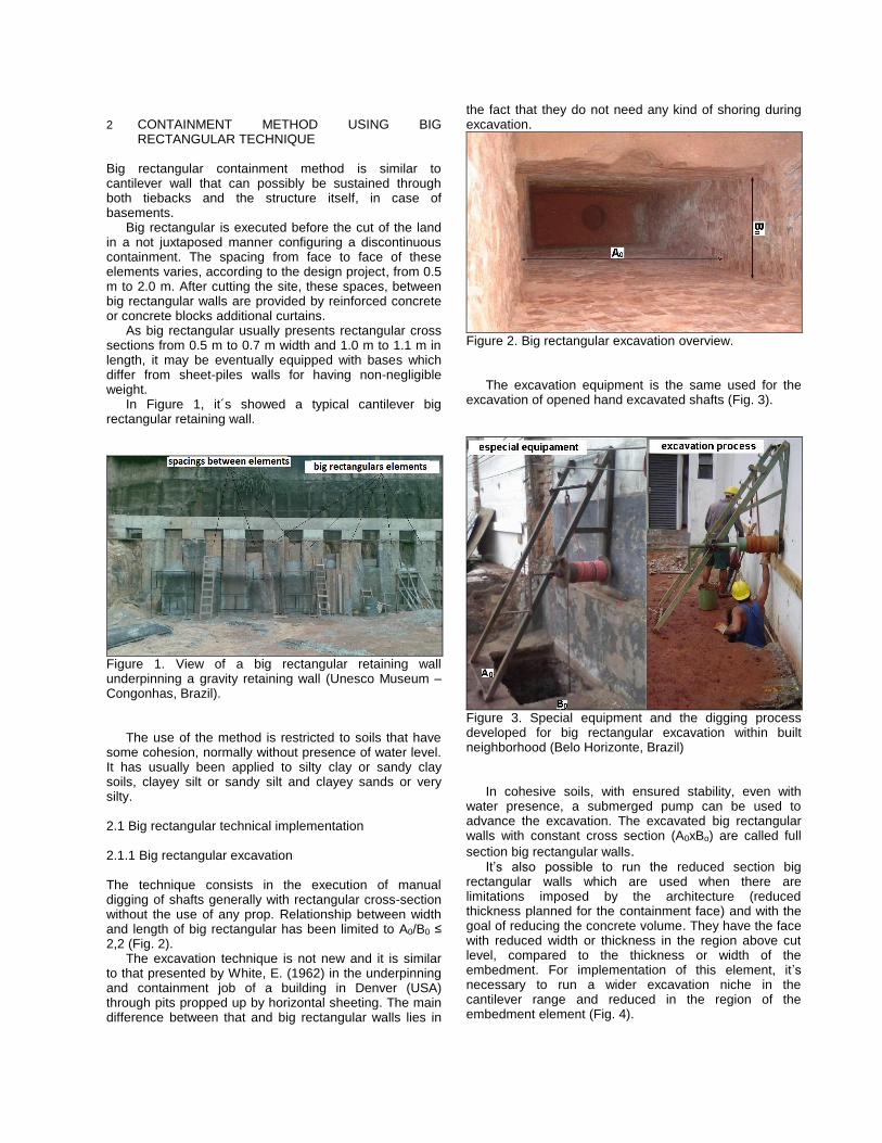
some cohesion, normally without presence of water level. It has usually been applied to silty clay or sandy clay soils, clayey silt or sandy silt and clayey sands or very silty. 2.1 Big rectangular technical implementation 2.1.1 Big rectangular excavation The technique consists in the execution of manual digging of shafts generally with rectangular cross-section without the use of any prop. Relationship between width and length of big rectangular has been limited to A0/B0 ≤ 2,2 (Fig. 2).
The excavation technique is not new and it is similar to that presented by White, E. (1962) in the underpinning and containment job of a building in Denver (USA) through pits propped up by horizontal sheeting. The main difference between that and big rectangular walls lies in
the fact that they do not need any kind of shoring during excavation.
Figure 2. Big rectangular excavation overview. The excavation equipment is the same used for the
excavation of opened hand excavated shafts (Fig. 3).
Figure 3. Special equipment and the digging process developed for big rectangular excavation within built neighborhood (Belo Horizonte, Brazil)
In cohesive soils, with ensured stability, even with
water presence, a submerged pump can be used to advance the excavation. The excavated big rectangular walls with constant cross section (A0xBo) are called full
section big rectangular walls. It’s also possible to run the reduced section big
rectangular walls which are used when there are limitations imposed by the architecture (reduced thickness planned for the containment face) and with the goal of reducing the concrete volume. They have the face with reduced width or thickness in the region above cut level, compared to the thickness or width of the embedment. For implementation of this element, it’s necessary to run a wider excavation niche in the cantilever range and reduced in the region of the embedment element (Fig. 4).
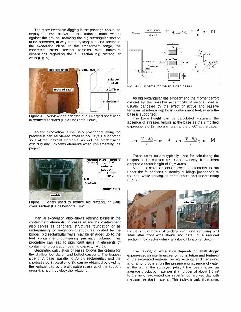
The more extensive digging in the passage above the deployment level allows the installation of molds waged against the ground, reducing the big rectangular section to be concreted, in way that they keep reduced section in the excavation niche. In the embedment range, the concreted cross section remains with minimum dimensions regarding the full section big rectangular walls (Fig. 5).
Figure 4. Overview and scheme of a enlarged shaft used in reduced sections (Belo Horizonte, Brazil).
As the excavation is manually proceeded, along the
process it can be viewed crossed soil layers supporting soils of the restraint elements, as well as interferences with dug and unknown elements when implementing the project.
Figure 5. Molds used to reduce big rectangular walls cross section (Belo Horizonte, Brazil).
Manual excavation also allows opening bases in the
containment elements. In cases where the containment also serves as peripheral structures foundation or as underpinning for neighboring structures located by the border, big rectangular walls may be enlarged up to the foot containment configuring prismatic volume. This procedure can lead to significant gains in elements of containment-foundation bearing capacity (Fig 6).
Geometric calculation of bases follows the criteria for the shallow foundation and belled caissons. The biggest side of A base, parallel to A0 big rectangular, and the shortest side B, parallel to B0, can be obtained by dividing the vertical load by the allowable stress qa of the support ground, since they obey the relations:
BA
forceaxialqapplied
for aapplied qq e 5,2
B
A [1]
Figure 6. Scheme for the enlarged bases
As big rectangular has embedment, the moment effort caused by the possible eccentricity of vertical load is usually canceled by the effect of active and passive tensions at inferior depths in containment foot, where the base is supported.
The base height can be calculated assuming the absence of stresses tensile at the base as the simplified expressions of [2], assuming an angle of 60º at the base:
º602
)( 0 tgAA
HB & º602
)( 0 tgBB
HB [2]
These formulas are typically used for calculating the
heights of the caisson bell. Conservatively, it has been adopted a footer height of R0 = 30cm.
Manual excavation also allows the elements to run under the foundations of nearby buildings juxtaposed to the site, while serving as containment and underpinning (Fig. 7).
Figure 7. Examples of underpinning and retaining wall sites after front excavations and detail of a reduced section in big rectangular walls (Belo Horizonte, Brazil).
The velocity of excavation depends on shaft digger
experience, on interferences, on constitution and features of the excavated material, on big rectangular dimensions, and, among others, on the presence or absence of water in the pit. In the surveyed jobs, it has been raised an average production rate per shaft digger of about 1.8 m³ to 2.8 m³ of excavated soil in an 8-hour worked day with medium resistant material. This index is only illustrative,
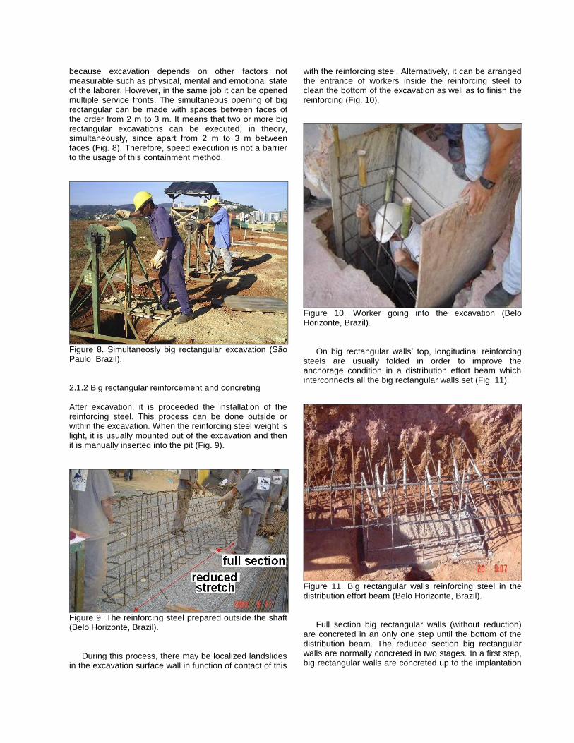
because excavation depends on other factors not measurable such as physical, mental and emotional state of the laborer. However, in the same job it can be opened multiple service fronts. The simultaneous opening of big rectangular can be made with spaces between faces of the order from 2 m to 3 m. It means that two or more big rectangular excavations can be executed, in theory, simultaneously, since apart from 2 m to 3 m between faces (Fig. 8). Therefore, speed execution is not a barrier to the usage of this containment method.
Figure 8. Simultaneosly big rectangular excavation (São Paulo, Brazil).
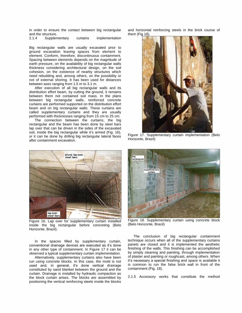
2.1.2 Big rectangular reinforcement and concreting
After excavation, it is proceeded the installation of the reinforcing steel. This process can be done outside or within the excavation. When the reinforcing steel weight is light, it is usually mounted out of the excavation and then it is manually inserted into the pit (Fig. 9).
Figure 9. The reinforcing steel prepared outside the shaft (Belo Horizonte, Brazil).
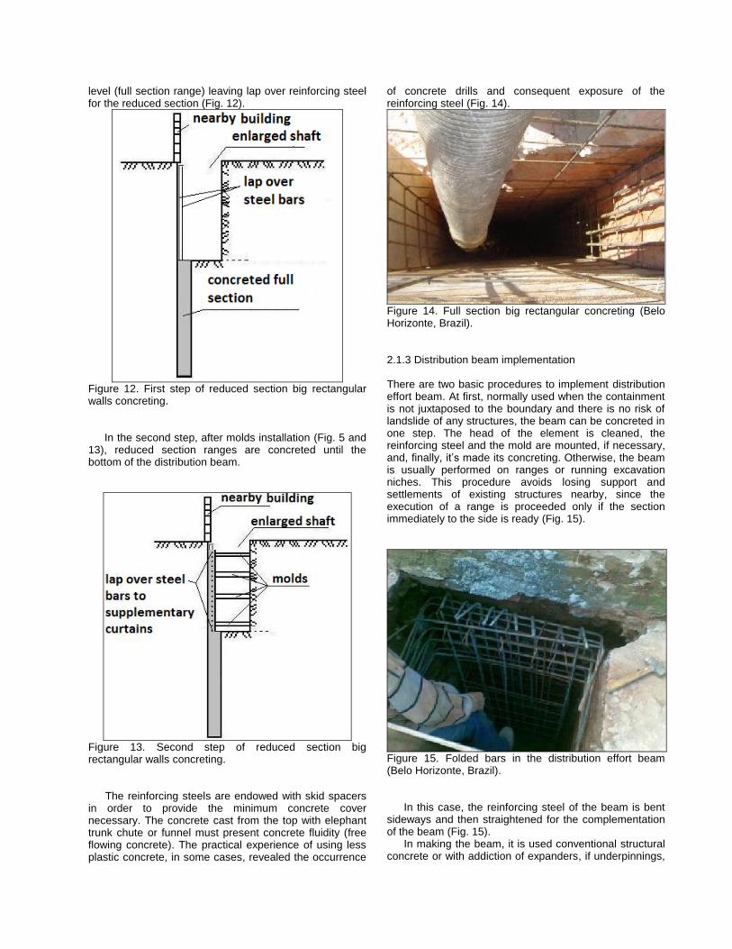
During this process, there may be localized landslides
in the excavation surface wall in function of contact of this
with the reinforcing steel. Alternatively, it can be arranged the entrance of workers inside the reinforcing steel to clean the bottom of the excavation as well as to finish the reinforcing (Fig. 10).
Figure 10. Worker going into the excavation (Belo Horizonte, Brazil).
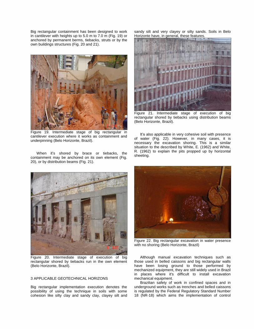
On big rectangular walls’ top, longitudinal reinforcing steels are usually folded in order to improve the anchorage condition in a distribution effort beam which interconnects all the big rectangular walls set (Fig. 11).
Figure 11. Big rectangular walls reinforcing steel in the distribution effort beam (Belo Horizonte, Brazil).
Full section big rectangular walls (without reduction)
are concreted in an only one step until the bottom of the distribution beam. The reduced section big rectangular walls are normally concreted in two stages. In a first step, big rectangular walls are concreted up to the implantation
level (full section range) leaving lap over reinforcing steel for the reduced section (Fig. 12).
Figure 12. First step of reduced section big rectangular walls concreting.
In the second step, after molds installation (Fig. 5 and
13), reduced section ranges are concreted until the bottom of the distribution beam.
Figure 13. Second step of reduced section big rectangular walls concreting.
The reinforcing steels are endowed with skid spacers in order to provide the minimum concrete cover necessary. The concrete cast from the top with elephant trunk chute or funnel must present concrete fluidity (free flowing concrete). The practical experience of using less plastic concrete, in some cases, revealed the occurrence
of concrete drills and consequent exposure of the reinforcing steel (Fig. 14).
Figure 14. Full section big rectangular concreting (Belo Horizonte, Brazil).
2.1.3 Distribution beam implementation There are two basic procedures to implement distribution effort beam. At first, normally used when the containment is not juxtaposed to the boundary and there is no risk of landslide of any structures, the beam can be concreted in one step. The head of the element is cleaned, the reinforcing steel and the mold are mounted, if necessary, and, finally, it’s made its concreting. Otherwise, the beam is usually performed on ranges or running excavation niches. This procedure avoids losing support and settlements of existing structures nearby, since the execution of a range is proceeded only if the section immediately to the side is ready (Fig. 15).
Figure 15. Folded bars in the distribution effort beam (Belo Horizonte, Brazil).
In this case, the reinforcing steel of the beam is bent sideways and then straightened for the complementation of the beam (Fig. 15).
In making the beam, it is used conventional structural concrete or with addiction of expanders, if underpinnings,
in order to ensure the contact between big rectangular and the structure.
2.1.4 Supplementary curtains implementation Big rectangular walls are usually excavated prior to ground excavation leaving spaces from element to element. Conform, therefore, discontinuous containment. Spacing between elements depends on the magnitude of earth pressure, on the availability of big rectangular walls thickness considering architectural design, on the soil cohesion, on the existence of nearby structures which need rebuilding and, among others, on the possibility or not of external shoring. It has been used for distances between axes ranging from 1.5 m to 3.1 m.
After execution of all big rectangular walls and its distribution effort beam, by cutting the ground, it remains between them not contained soil mass. In the plans between big rectangular walls, reinforced concrete curtains are performed supported on the distribution effort beam and on big rectangular walls. These curtains are called supplementary curtains and they are usually performed with thicknesses ranging from 15 cm to 25 cm.
The connection between the curtains, the big rectangular and the beam has been done by steel bars lap over that can be driven in the sides of the excavated soil, inside the big rectangular while it’s armed (Fig. 16), or it can be done by drilling big rectangular lateral faces after containment excavation.
Figure 16. Lap over for supplementary curtain installed inside the big rectangular before concreting (Belo Horizonte, Brazil).
In the spaces filled by supplementary curtain, conventional drainage devices are executed as it’s done in any other type of containment. In Figure 17 it can be observed a typical supplementary curtain implementation.
Alternatively, supplementary curtains also have been run using concrete blocks. In this case, the mold is not used and, in general, it’s done vertical drainage constituted by sand blanket between the ground and the curtain. Drainage is installed by hydraulic compaction as the block curtain arises. The blocks are assembled by positioning the vertical reinforcing steels inside the blocks
and horizontal reinforcing steels in the brick course of them (Fig 18).
Figure 17. Supplementary curtain implementation (Belo Horizonte, Brazil)
Figure 18. Supplementary curtain using concrete block (Belo Horizonte, Brazil)
The conclusion of big rectangular containment
technique occurs when all of the supplementary curtains panels are closed and it is implemented the aesthetic finishing of the walls. This finishing can be accomplished by simply cleaning and painting, through implementation of plaster and painting or roughcast, among others. When it’s necessary a special finishing and space is available it is common to run the false brick wall in front of the containment (Fig. 18).
2.1.5 Accessory works that constitute the method
Big rectangular containment has been designed to work in cantilever with heights up to 5.0 m to 7.0 m (Fig. 19) or anchored by permanent berms, tiebacks, struts or by the own buildings structures (Fig. 20 and 21).
Figure 19. Intermediate stage of big rectangular in cantilever execution where it works as containment and underpinning (Belo Horizonte, Brazil).
When it’s shored by brace or tiebacks, the containment may be anchored on its own element (Fig. 20), or by distribution beams (Fig. 21).
Figure 20. Intermediate stage of execution of big rectangular shored by tiebacks run in the own element (Belo Horizonte, Brazil). 3 APPLICABLE GEOTECHNICAL HORIZONS Big rectangular implementation execution denotes the possibility of using the technique in soils with some cohesion like silty clay and sandy clay, clayey silt and
sandy silt and very clayey or silty sands. Soils in Belo Horizonte have, in general, these features.
Figure 21. Intermediate stage of execution of big rectangular shored by tiebacks using distribution beams (Belo Horizonte, Brazil).
It’s also applicable in very cohesive soil with presence of water (Fig. 22). However, in many cases, it is necessary the excavation shoring. This is a similar situation to the described by White, E. (1962) and White, R. (1962) to explain the pits propped up by horizontal sheeting.
Figure 22. Big rectangular excavation in water presence with no shoring (Belo Horizonte, Brazil)
Although manual excavation techniques such as
those used in belled caissons and big rectangular walls have been losing ground to those performed by mechanized equipment, they are still widely used in Brazil in places where it's difficult to install excavation mechanical equipment.
Brazilian safety of work in confined spaces and in underground works such as trenches and belled caissons is regulated by the Federal Regulatory Standard Number 18 (NR-18) which aims the implementation of control
measures and preventive safety systems in processes, conditions and working environment on the construction industry. The same security items applied to questions on safety performance of belled caissons are applied to big rectangular walls. In these cases, the NR-18 determines that the need of shoring in the excavation or not is up to the geotechnical engineer responsible for the project, considering the security requirements (Associação Brasileira de Normas Técnicas 1998).
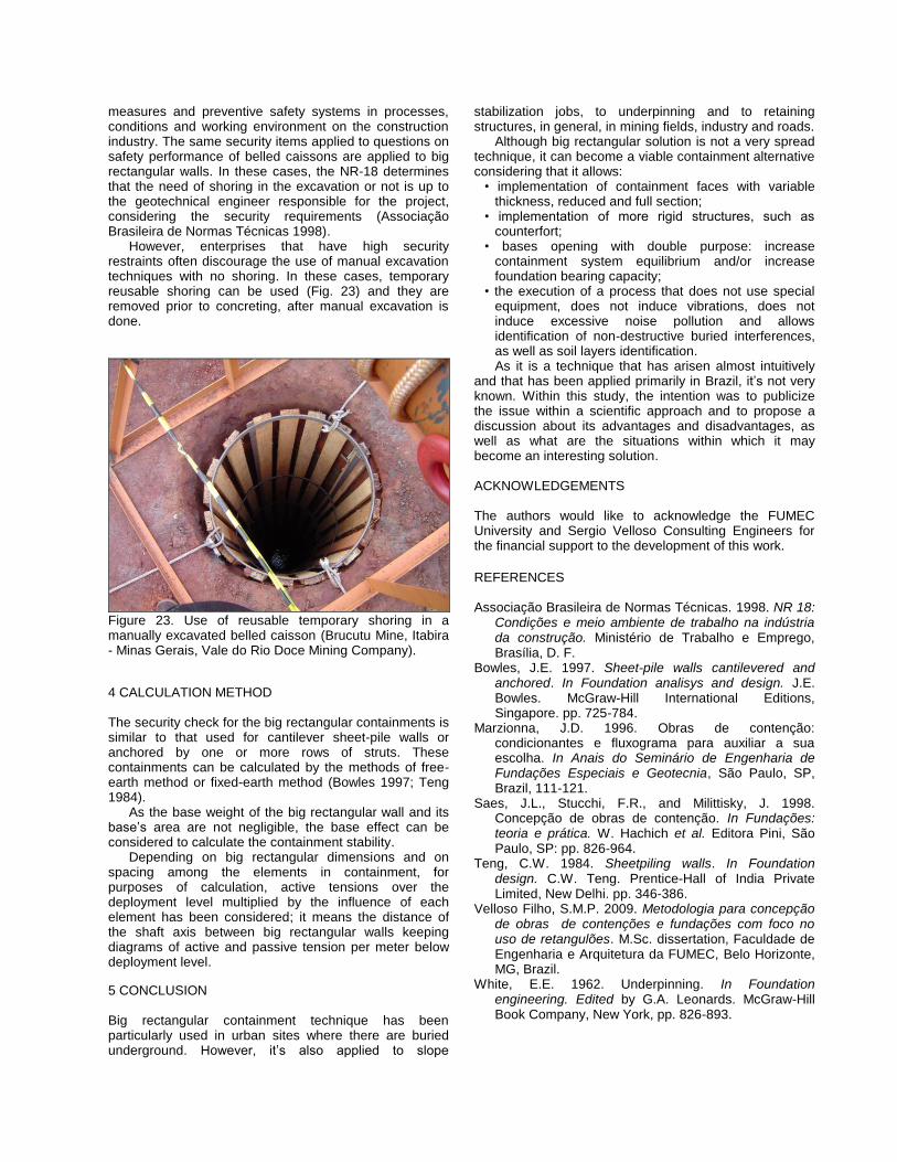
However, enterprises that have high security restraints often discourage the use of manual excavation techniques with no shoring. In these cases, temporary reusable shoring can be used (Fig. 23) and they are removed prior to concreting, after manual excavation is done.
Figure 23. Use of reusable temporary shoring in a manually excavated belled caisson (Brucutu Mine, Itabira - Minas Gerais, Vale do Rio Doce Mining Company).
4 CALCULATION METHOD The security check for the big rectangular containments is similar to that used for cantilever sheet-pile walls or anchored by one or more rows of struts. These containments can be calculated by the methods of free-earth method or fixed-earth method (Bowles 1997; Teng 1984).
As the base weight of the big rectangular wall and its base’s area are not negligible, the base effect can be considered to calculate the containment stability.
Depending on big rectangular dimensions and on spacing among the elements in containment, for purposes of calculation, active tensions over the deployment level multiplied by the influence of each element has been considered; it means the distance of the shaft axis between big rectangular walls keeping diagrams of active and passive tension per meter below deployment level.
5 CONCLUSION
Big rectangular containment technique has been particularly used in urban sites where there are buried underground. However, it’s also applied to slope
stabilization jobs, to underpinning and to retaining structures, in general, in mining fields, industry and roads.
Although big rectangular solution is not a very spread technique, it can become a viable containment alternative considering that it allows:
• implementation of containment faces with variable thickness, reduced and full section;
• implementation of more rigid structures, such as counterfort;
• bases opening with double purpose: increase containment system equilibrium and/or increase foundation bearing capacity;
• the execution of a process that does not use special equipment, does not induce vibrations, does not induce excessive noise pollution and allows identification of non-destructive buried interferences, as well as soil layers identification. As it is a technique that has arisen almost intuitively
and that has been applied primarily in Brazil, it’s not very known. Within this study, the intention was to publicize the issue within a scientific approach and to propose a discussion about its advantages and disadvantages, as well as what are the situations within which it may become an interesting solution.
ACKNOWLEDGEMENTS The authors would like to acknowledge the FUMEC University and Sergio Velloso Consulting Engineers for the financial support to the development of this work.
REFERENCES Associação Brasileira de Normas Técnicas. 1998. NR 18:
Condições e meio ambiente de trabalho na indústria da construção. Ministério de Trabalho e Emprego, Brasília, D. F.
Bowles, J.E. 1997. Sheet-pile walls cantilevered and anchored. In Foundation analisys and design. J.E. Bowles. McGraw-Hill International Editions, Singapore. pp. 725-784.
Marzionna, J.D. 1996. Obras de contenção: condicionantes e fluxograma para auxiliar a sua escolha. In Anais do Seminário de Engenharia de Fundações Especiais e Geotecnia, São Paulo, SP, Brazil, 111-121.
Saes, J.L., Stucchi, F.R., and Milittisky, J. 1998. Concepção de obras de contenção. In Fundações: teoria e prática. W. Hachich et al. Editora Pini, São Paulo, SP: pp. 826-964.
Teng, C.W. 1984. Sheetpiling walls. In Foundation design. C.W. Teng. Prentice-Hall of India Private Limited, New Delhi. pp. 346-386.
Velloso Filho, S.M.P. 2009. Metodologia para concepção de obras de contenções e fundações com foco no uso de retangulões. M.Sc. dissertation, Faculdade de Engenharia e Arquitetura da FUMEC, Belo Horizonte, MG, Brazil.
White, E.E. 1962. Underpinning. In Foundation engineering. Edited by G.A. Leonards. McGraw-Hill Book Company, New York, pp. 826-893.

White, R.E. 1962. Caissons and cofferdams. In Foundation engineering. Edited by G.A. Leonards. McGraw-Hill Book Company, New York, pp. 894-964.