Embed Size (px)
Citation preview
Review ArticleModelling of Physical, Chemical, and Material Properties ofSolid Oxide Fuel Cells
Jakub Kupecki
Thermal Processes Department, Institute of Power Engineering, Augustowka 36, 00-981 Warsaw, Poland
Correspondence should be addressed to Jakub Kupecki; [email protected]
Received 29 September 2014; Revised 4 December 2014; Accepted 5 December 2014
Academic Editor: Xiao-Dong Wang
Copyright © 2015 Jakub Kupecki.This is an open access article distributed under theCreativeCommonsAttribution License, whichpermits unrestricted use, distribution, and reproduction in any medium, provided the original work is properly cited.
This paper provides a review of modelling techniques applicable for system-level studies to account for physical, chemical, andmaterial properties of solid oxide fuel cells. Functionality of 0D to 3Dmodels is discussed and selected examples are given. Authorprovides information on typical length scales in evaluation of power systems with solid oxide fuel cells. In each section, properexamples of previous studies done in the field of 0D–3D modelling are recalled and discussed.
1. Introduction
The development of innovative power systems requires con-tinuous development of tools allowing modelling and simu-lation of their operation under different working conditions.Specific properties of solid oxide fuel cells related to physical,chemical, and material parameters enforce the need foradvanced numerical models at different levels to accountfor numerous parameters. Different modelling methods areunder considerations. Application-specific criteria and vari-ous designs require dedicated approach and methodology.
In general, models are used to help understanding thebehaviour of a particular system in certain operating con-ditions and can be used to optimise control strategy, design,thermal balancing, and other parameters. Additionally, mod-els can be used as predictive tools for performance evalu-ation under nonnominal conditions. Moreover, modellingfollowed by optimisation can provide crucial informationfor the improvements in the design and functionality. Forthis purpose steady state and/or dynamic evaluations can beperformed. In this paper only the steady state operation isconsidered.
Validity range of different modelling techniques dependson the user-specified criteria. While in certain cases use ofdetailed 3D models might be required, in some situations
simple reproduction of experimental data can be sufficient.Selection of method has to correspond to the purpose of thestudy, both including level of details and selection of eithersteady-state or transient analysis. In each case, determinationof crucial criteria is an important step and must be done withcaution.
In a comprehensive review of modelling methods by Anget al. [1], the most commonly used approaches were dis-cussed, including numerous parametric studies, single- andmultiobjective optimisation. Indeed, themain purpose of anynumerical study is to evaluate influence of and interactionsbetween selected parameters. Optimisation always targets atfinding the best operating mode when either one or moreparameters are manipulated. Depending on the requiredcomplexity and level of details, different methods can beselected and used.
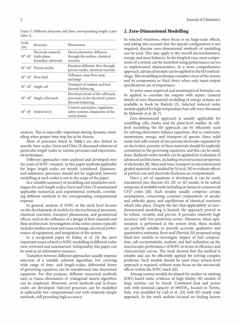
During SOFC-based system operation numerous pro-cesses are taking place at wide range of length- and time-scales. Selection of a modelling method must be based onits capability of covering these processes in a sufficient wayand with a required accuracy. Summary of typically con-sidered phenomena with their corresponding length scalesis presented in Table 1 after [2]. Additionally, correspondingtime scales have to be taken into account while developingmathematical description of processes involved in transient
Hindawi Publishing CorporationJournal of ChemistryVolume 2015, Article ID 414950, 7 pageshttp://dx.doi.org/10.1155/2015/414950
2 Journal of Chemistry
Table 1: Different processes and their corresponding length scales[after 1].
Scale[m] Structure Phenomena
108–107Electrode material,triple phaseboundary-electrode
Electrochemistry, diffusionthrough the surface, chemicalreaction
107–105 Porous media Knudsen diffusion, flow throughporous media, chemical reaction
105–103 Flow field Diffusion, mass flow, heatexchange
103–102 Single cell Transport of oxidant and fuel,thermal balancing
102–100 Single cells/stackElectrical circuit of the cell/stack,processes in the electrical system,thermal balancing
100–101 System levelControl, automatics, regulation,safety systems, integration of theentire system
analysis. This is especially important during dynamic mod-elling when proper time step has to be chosen.
Most of processes listed in Table 1 are also linked tospecific time-scales. Grew and Chiu [3] discussed relations ofparticular length scales to various processes and experimen-tal techniques.
Different approaches were analysed and developed overthe years of SOFC research. In this paper methods applicablefor larger length scales are mostly considered. Quantum-and subatomic processes should not be neglected; howevermodelling at such scales is not in the scope of the paper.
In a valuable summary of modelling and simulation tech-niques for such length scales, Grew and Chiu [3] summarisedapplicable numerical and experimental methods, correlat-ing different methods to the corresponding computationalexpense.
In general, analysis of SOFC at the stack level focuseson the development of models for electrochemical processes,chemical reactions, transport phenomena, and geometricaleffects, such as the influence of a design of flow channels andtheir architecture. Investigation of the entire system typicallyincludes studies on heat andmass exchange, electrical perfor-mance of equipment, and integration of the system.
In a recognised paper by Kakac et al. [4] the mostimportant issues related to SOFCmodelling at different scaleswere reviewed and summarised. Indisputably, this paper canbe used as an informative resource.
Transition between different approaches usually imposesselection of a suitable solution algorithm. For coveringwide range of time- and length-scales, differential formsof governing equations can be transformed into discretisedequations. For that purpose, different numerical methodssuch as Gauss elimination or tridiagonal matrix algorithmcan be employed. Moreover, novel methods and in-housecodes are developed. Selected processes can be modelledat sufficiently low computational cost with relatively simplemethods, still providing high accuracy.
2. Zero-Dimensional Modelling
In selected situations, when focus is on large-scale effects,and taking into account that the spacial configuration is notrequired, discrete zero-dimensional methods of modellingcan be used. This may apply to the overall electrochemistry,energy, andmass balances. In the simplest case, most compo-nents of a system can be modelled using performance curvesor implemented characteristics. In a more comprehensiveapproach, advancedmodels can be applied in the 0Dmethod-ology.Thismodelling technique considersmost of the systemand its components as black boxes when only input-outputspecifications are of importance.
In some cases empirical and semiempirical formulas canbe applied to correlate the outputs with inputs. Generaldetails of zero-dimensional modelling of energy systems areavailable in book by Badyda [5]. Selected reduced ordermodels applied for high temperature fuel cells were discussedby Milewski et al. [6, 7].
Zero-dimensional approach is usually applicable formodelling cells, stacks, and for plant-level studies. In cell-level modelling the 0D approach can be efficiently usedfor solving elementary balance equations, that is, continuity,momentum, energy, and transport of species. Since solidoxide fuel cells consist of two porous electrodes separated byan electrolyte, porosity of these materials should be explicitlyconsidered in the governing equations, and this can be easilydone. Reduced-order models can be applied for evaluation ofadvanced architectures, including microstructural propertiesof electrodes [8]. Mass and ionic transport inmicrostructuralgradedmaterials was studied byNi et al. [9] to evaluate effectsof particle size and electrode thickness on overpotentials.
Once a set of equations is developed, it can be easilytransferred into discrete 1D, 2D, or 3D model, to be solvedusing one of available tools including in-house or commercialCFD codes [10]. Such models usually comprise certainassumptions, concerning constant composition of anodicand cathodic gases, and equilibrium of chemical reactionswhich take place. Despite the fact that applicability of zero-dimensional modelling is limited, the approach proved tobe robust, versatile, and precise. It provides relatively highaccuracy with low prediction errors. Moreover, when opti-misation is performed at the system level, these modelsare perfectly suitable to provide accurate qualitative andquantitative estimates. Bove andUbertini [11] proposed usingblack-box models to investigate impact of fuel composi-tion, cell overpotentials, oxidant, and fuel utilisation on themacroscopic performance of SOFC in terms of efficiency andcharacteristic curves. The work showed that the method isreliable and can be efficiently applied for solving complexproblems. Such models should be used when system-levelapproach is required, without main focus on the microscaleeffects within the SOFC stack [12].
Among various models developed for studies on existingSOFC-based units, evidence of high fidelity 0D models oflarge systems can be found. Combined heat and powerunit with nominal capacity of 100 kWel located in Torino,Italy, was modelled by Calı et al. [13] with 0D steady stateapproach. In the work authors focused on finding factors
Journal of Chemistry 3
of a high importance for system performance, rather thananalysing in detail physical and chemical relations betweenmicroscale phenomena involved in operation of the unit.Zero-dimensional approach aids in performing parametricstudies of SOFC performance with electrochemical modelstaking into account operational and structural parameters tocorrelate overpotentials with geometry and working condi-tions [14].
Generally, plant-level modelling is necessary to investi-gate particular applications. Such models can also providepredictive information about specific subsystems, includingfuel cell stack, fuel supply and processing, water, fuel and heatmanagement, power conditioning, and control equipment.These subsystems can and should be selected for optimisation[1], since only high performance of all components can assureoverall system efficiency at satisfactory level. In suchmanner,material properties of solid oxide fuel cells were evaluatedusing zero-dimensional model developed specifically forplant-level simulations [15].
Zero-dimensional models can be easily built and exe-cuted in one of popular commercial codes such as AspenHYSYS, Aspen Plus, gPROMS, and others, including userroutines developed in common programming languages.Some of the listed codes exhibit unique features which canbe useful in modelling of electrochemical energy conver-sion devices, such as fuel cells. Among the ones listed,Aspen HYSYS is an example of a versatile tool capable ofmodelling different components, machinery, chemical, andelectrochemical processes. Aspen HYSYS offers a compre-hensive foundation for accurate calculations of the physicalproperties and thermodynamic and transport properties inmost technological and chemical processes. Software provedto be capable of handling very advanced and complex powersystems with solid oxide fuel cells [16].
3. One- and Two-Dimensional Modelling
One- and two-dimensional models (1D and 2D) are typicallyused when effects of geometry have to be taken into account.This group of models is usually used to reduce computationalcost typical for solving fully three-dimensional models. Itis mostly done in situations when discretisation of partialand ordinary differential equations does not substantiallycompromise accuracy of the model, even when the geometryis simplified to a certain extent.
1D and 2D models can be applied for evaluation of dis-tribution of parameters along the flow channels for differentdomains in a fuel cell: fuel and air stream, anode-electrolyte-cathode structure, and interconnects. Mass transport in fueland air gas channels can be treated as a fully developedlaminar flow described sufficiently by means of velocity andtemperature. Flow patterns within fuel cell channels werepreviously studied, and laminar character was found to beindeed a proper assumption [2]. Additionally, in the system-level studies, one- and two-dimensional models can helpto evaluate thermal integration of components. Detailedinformation about interactions within the system structurecan support the designing process and contribute to maximi-sation of the system performance. Analysis of thermal and
chemical properties requires high attention especially duringpart-load operation of systems with fuel cells. Endothermicand exothermic processes have to be precisely balanced andthermal losses have to be compensated.
In previous studies good evidence of using 1D and 2Dapproaches to SOFC stacks can be found. Lai et al. [17]used the technique and developed tool suitable for analysisof SOFC stack containing up to 100 cells. They derived amodel where set of conservation equations was solved for1D case and later extrapolated for the entire stack; hencequasi-2Dmodel was obtained. Moreover, to allow simulationof broad range of cells, user-defined electrochemical modelwas employed. An in-house code, based on subroutines, wasimplemented in FORTRAN, with typical tolerances for tem-perature and current of 0.1 and 1%, respectively. Predictions ofthe model for the benchmark cases with and without on-cellmethane reforming were compared with results from otherstudies described in the literature, and good agreement wasachieved.
The approach also finds application in predicting distri-bution of chemical species and evaluation of temperatureprofiles. Mahcene et al. [18] used 2D tool to model coflowplanar anode supported SOFC as a single unit and studiedinfluence of the porosity of a thick (500𝜇) anode on a cellperformance.
In work by Jewulski et al. [19] flow distribution ofreactants was studied using 2D model. Simulation of thegas flow, local fuel utilisation, and pressure distribution inthe internally manifolded stack showed good results andagreement with the analytical model. Moreover, 2D tool wassufficient to obtain convergence with experimental data.
Summarising, one- and two-dimensional models can beemployed both at the micro- and macroscales in order toanalyse most of phenomena ranging from flow patterns inthe microporous structures of fuel cell assemblies up to theintegration of components at the system-level.
4. Three-Dimensional Modelling andComputational Fluid Dynamics Codes
The most comprehensive approach, which can be used forsimulation of most processes involved in power generationin SOFC-based system, is the fully three-dimensional mod-elling. Method is relevant for most issues listed previouslyin Table 1. Moreover, such approach can be used not onlyto aid in designing, evaluation, and optimisation of systemcomponents, but also for studies related to interactionsbetween them. By these mean spacial arrangements, thermalbalancing and integration of system components can beimproved for high overall performance. Applicability rangeof fully 3D models is theoretically unlimited; however com-putational cost might be the limiting factor. Typically, thisapproach is selected only for detailed analysis of a particularstructure or process. Moreover, high computational costmakes these models not suitable for evaluation of the systemduring dynamic operation, and mostly single operationalpoint is investigated.
Among available literature on 3D modelling of differentaspects of solid oxide fuel cells, selected papers on the topic
4 Journal of Chemistry
should be noted. In early 1990s, Achenbach [20] employednumerical tool to investigate heat conductivity of a stack forceramic andmetallic plates. With the proposedmethodologyit was possible to compute overall heat conductivities of thesematerials. Values of 2Wm−1 K−1 and 27Wm−1 K−1 werefound for the former and latter, respectively. Additionally,model was used to evaluate radiation influence on the totalamount of heat generated by the stack. Depending on thematerial, radiation accounted to 7% and 22% of total heatlosses from ceramic and metallic stack, respectively. In workby Tanaka et al. [21] detailed study on SOFC stack wasperformed. Authors investigated heat exchange, with specialfocus on heat radiation within the stack. Numerical tool,which allowed to precisely predict temperature distributionin flow channels, was developed and used in the study.Additionally, tool was employed to determine average singlecell voltage for different ambient conditions.
Kattke et al. [22] modelled highly integrated SOFC-based system with 3D approach combined with 1D modelof a tubular SOFC stack. In the work quasi-one-dimensionalmodel was used to simulate balance of plant (BoP) com-ponents, including catalytic partial oxidation fuel processorand tail gas combustor. Integration and interactions betweensystem components were studied using computational fluiddynamic code. The prototype unit with nominal gross powerof 650Wel was simulated. This methodology was one of avery few approaches, when interactions between micro-CHPsystem components were of a high attention. Paper shouldbe considered as a highly valuable contribution due to thefact that previously nobody really studied influence of SOFCstack on the other system components located close to eachother. Generally, the work was merging scientific approachwith aspects related to the design and construction; thereforeit is a good resource for the development of solutions forproblems handled by mathematical models of fuel cells.Moreover, the approach proposed byKattke et al. was actuallyaddressing another major issue. In vast majority of previousstudies, adiabatic SOFC stack was considered; however suchapproach has no physical meaning, and cannot be applied foranalysis of systems.
Fully three-dimensional models can allow evaluation ofSOFC-based systemwithout oversimplifying or even neglect-ing certain aspects. System design and simulation modelsfound in the extant literature typically employ approachesthat either
(i) assume adiabatic conditions for components of asystem [23],
(ii) employ thermodynamic models to predict therequired heat loss from components based on a giveninlet and outlet state [12], or
(iii) calculate component heat losses without any thermalcoupling [23–25].
Such approaches do not allow to capture the thermoflu-idic interactions between components nor do they quantifythe effect of thermal coupling on the system performance.Generally significant thermal interactions are found espe-cially in micro- and small-scale units, including portable
and mobile applications. For this purpose, Kattke and Braun[26] implemented thermalmanagementmodelling tool into asystemmodel that includes interactions between componentsfor small, mobile application based on planar SOFC, usingrelatively simple thermal resistance approach. The studyshowed how oversimplified the oxidant flow requirement,recuperator heat duty, and other parameters could be whenheat exchange by convection and radiation is neglected. Sum-marising, in a general case, for all computational approachesand different solution algorithms, the following input infor-mation must be specified by the user to account for
(i) cell’s geometry and parameters (number and designof flow channels, their dimensions, length, width, andheight of cell, thickness of interconnects, materialtypes, and their properties, etc.),
(ii) thermodynamic state (temperature and pressure) andcomposition of fuel and oxidant at the inlet,
(iii) boundary conditions (temperature of the surround-ing top, bottom, front, back, and side enclosuresincluding thermal conductivity, emissivity, and otherthermal parameters),
(iv) operating conditions of cells in different workingmodes.
The model should be capable of solving the multiphysicssystem and predict the following information for the SOFCsystem:
(i) overall SOFC stack performance: total power output,fuel and air utilisation, heat loss at each side of theboundary, working voltage, and current density foreach cell in the stack,
(ii) detailed profiles of various thermophysical param-eters: temperature, current density, species compo-sition, and heat generation in each control volume(fuel, air, positive-electrolyte-negative (PEN) struc-tures, and interconnects).
For this purpose, hybrid multidimensional models areoften used. Certain components are treated with quasi-one-dimensional approach, while the other are treated with 1Dor 2D technique. Despite the fact that such methodologyallows covering most of the occurring phenomena, at thispoint question may arise if the reliability level of the modelis sufficient. In any case, results should be validated withexperimental data or at least verified by comparison withalternative models. Razbani et al. [27] performed experimen-tally validated numerical analysis of electrolyte supportedsix-cell SOFC stack fed by biogas using 3D modelling inCOMSOL Multiphysics. Comprehensive CFD models findapplication in simulation of fuel cells with different supports,both for high [28] and for intermediate temperature designs[29].
Several papers present results of modelling of fuel pro-cessing, including internal reforming [30] and partial pre-reforming of different gas mixtures [31]. Studies on directinternal reforming in solid oxide fuel cells require couplingof models for electrochemical and catalytic processes with
Journal of Chemistry 5
simulation of mass transfer in porous media. For that reasoneither 2D or 3D models are used for solving the elementarymass and energy balances and evaluation of transport inporous media.
If decision is made to analyse the entire system by solvingsets of fully 3D governing equations, computer codes such asAnsys Fluent, Ansys CFX, Open FOAM, Cantera, Python,and in-house software can be used. High computationalexpense, enormous number of nodes, and other factorsusually justify selection of simplified methods.
5. Investigation of Manifolds Geometry
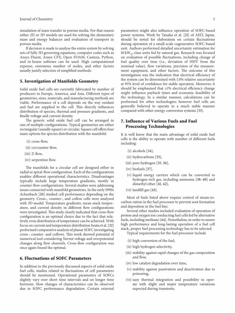
Solid oxide fuel cells are currently fabricated by number ofproducers in Europe, America, and Asia. Different types ofgeometries, sizes, materials, and manufacturing methods areviable. Performance of a cell depends on the way oxidantand fuel are supplied to the cell. This directly influencesdistribution of species, thermal and pressure gradients, andfinally voltage and current density.
The generic solid oxide fuel cell can be arranged inone of multiple configurations. Typical geometries are eitherrectangular (usually square) or circular. Square cell offers fourmain options for species distribution with the manifold:
(i) cross-flow,(ii) co/counter-flow,(iii) Z-flow,(iv) serpentine flow.
The manifolds for a circular cell are designed either inradial or spiral-flow configuration. Each of the configurationsenables different operational characteristics. Disadvantagestypically include large temperature gradients, mostly incounter-flow configurations. Several studies were addressingissues connectedwithmanifold geometries. In the early 1990sAchenbach [20] studied cell performance depending on thegeometry. Cross-, counter-, and coflow cells were analysedwith 3D model. Temperature gradients, mean stack temper-ature, and current density in different flow configurationswere investigated.This study clearly indicated that cross-flowconfiguration is an optimal choice due to the fact that rela-tively even distribution of temperature can be achieved.Withfocus on current and temperature distribution Iwata et al. [32]performed comparative analysis of planar SOFC investigatingcross-, counter- and coflows. This work showed potential ofnumerical tool considering Nernst voltage and overpotentialchanges along flow channels. Cross-flow configuration wasonce again found the optimal.
6. Fluctuations of SOFC Parameters
In addition to the previously discussed aspects of solid oxidefuel cells, studies related to fluctuations of cell parametersshould be mentioned. Operational parameters of SOFCsslightly vary over short time intervals and on longer timehorizons. Slow changes of characteristics can be observeddue to SOFC performance degradation. Certain external
parameters might also influence operation of SOFC-basedpower systems. Work by Tanaka et al. [21] of AIST, Japan,should be noted for elaboration on certain fluctuationsduring operation of a small-scale cogenerative SOFC-basedunit. Authors performed detailed uncertainty estimation for10 kWel-class units fed by natural gas. Research was focusedon evaluation of possible fluctuations, including change offuel quality over time (i.e., deviation of HHV from thenominal value), flow variations, precision of the measure-ment equipment, and other factors. The outcome of thisinvestigation was the indication that electrical efficiency ofthe system can be determined with 1.0% relative uncertaintyat 95% level of confidence for stable operation. Moreover, itshould be emphasised that ±1% electrical efficiency changemight influence payback times and economic feasibility ofthe technology. In a similar manner, calculations can beperformed for other technologies; however fuel cells aregenerally believed to operate in a much stable mannercompared with other energy conversion systems [33].
7. Influence of Various Fuels and FuelProcessing Technologies
It is well know that the main advantage of solid oxide fuelcells is the ability to operate with number of different fuelsincluding:
(i) alcohols [34],(ii) hydrocarbons [33],(iii) pure hydrogen [35, 36],(iv) biofuels [37],(v) liquid energy carriers which can be converted to
hydrogen-rich gas, including ammonia [38–40] anddimethyl ether [41, 42],
(vi) landfill gas [43].
Most of fuels listed above require control of steam-to-carbon ration in the fuel processor to prevent soot formationand deposition in the fuel line.
Several other studies included evaluation of operation ofproton and oxygen ion conducting fuel cells fed by alternativefuels, includingmethane [44]. Nonetheless, in order to assurehigh performance and long-lasting operation of a fuel cellstack, proper fuel processing technology has to be selected.
Typical requirements for the fuel processor include
(i) high conversion of the fuel,(ii) high hydrogen selectivity,(iii) stability against rapid changes of the gas composition
and flow,(iv) low catalyst degradation over time,(v) stability against passivation and deactivation due to
poisoning,(vi) easy thermal integration and possibility to oper-
ate with slight and major temperature variationsexpected during transients,
6 Journal of Chemistry
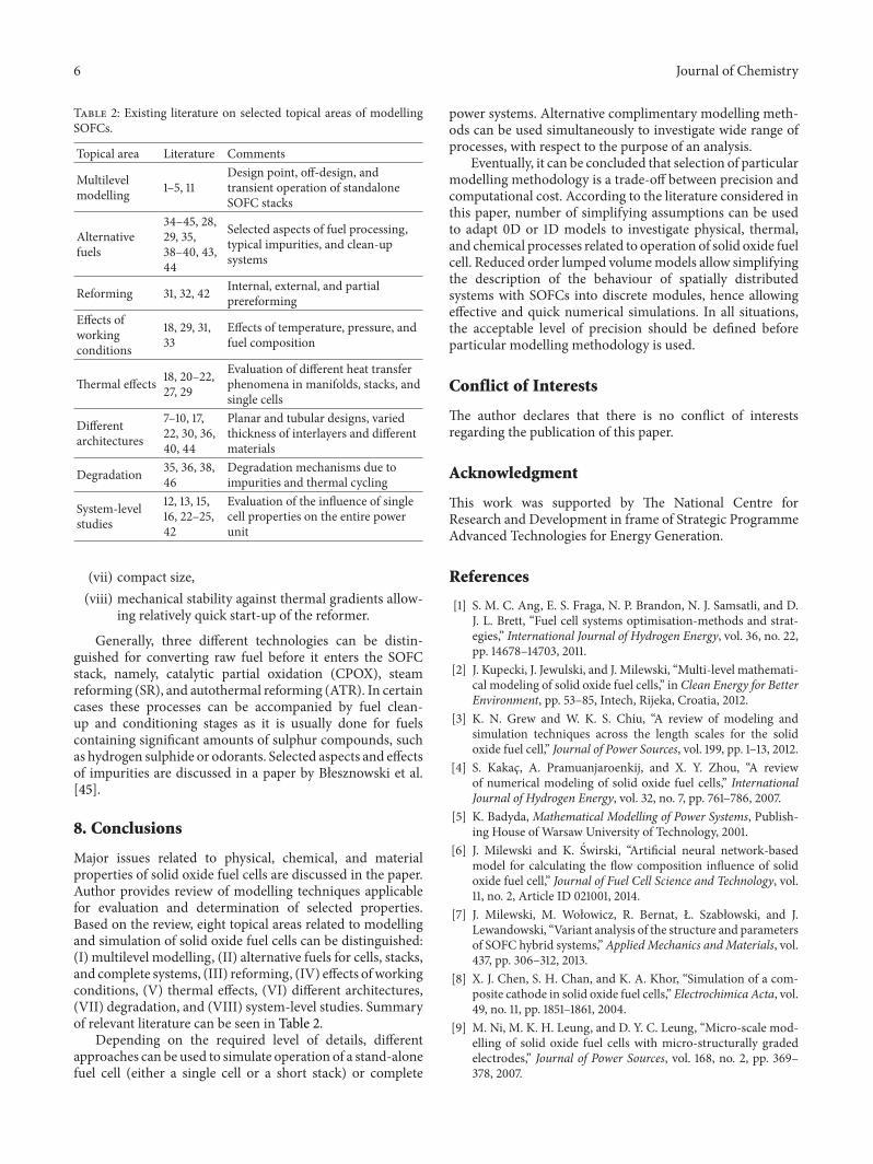
Table 2: Existing literature on selected topical areas of modellingSOFCs.
Topical area Literature Comments
Multilevelmodelling 1–5, 11
Design point, off-design, andtransient operation of standaloneSOFC stacks
Alternativefuels
34–45, 28,29, 35,38–40, 43,44
Selected aspects of fuel processing,typical impurities, and clean-upsystems
Reforming 31, 32, 42 Internal, external, and partialprereforming
Effects ofworkingconditions
18, 29, 31,33
Effects of temperature, pressure, andfuel composition
Thermal effects 18, 20–22,27, 29
Evaluation of different heat transferphenomena in manifolds, stacks, andsingle cells
Differentarchitectures
7–10, 17,22, 30, 36,40, 44
Planar and tubular designs, variedthickness of interlayers and differentmaterials
Degradation 35, 36, 38,46
Degradation mechanisms due toimpurities and thermal cycling
System-levelstudies
12, 13, 15,16, 22–25,42
Evaluation of the influence of singlecell properties on the entire powerunit
(vii) compact size,(viii) mechanical stability against thermal gradients allow-
ing relatively quick start-up of the reformer.
Generally, three different technologies can be distin-guished for converting raw fuel before it enters the SOFCstack, namely, catalytic partial oxidation (CPOX), steamreforming (SR), and autothermal reforming (ATR). In certaincases these processes can be accompanied by fuel clean-up and conditioning stages as it is usually done for fuelscontaining significant amounts of sulphur compounds, suchas hydrogen sulphide or odorants. Selected aspects and effectsof impurities are discussed in a paper by Błesznowski et al.[45].
8. Conclusions
Major issues related to physical, chemical, and materialproperties of solid oxide fuel cells are discussed in the paper.Author provides review of modelling techniques applicablefor evaluation and determination of selected properties.Based on the review, eight topical areas related to modellingand simulation of solid oxide fuel cells can be distinguished:(I) multilevel modelling, (II) alternative fuels for cells, stacks,and complete systems, (III) reforming, (IV) effects of workingconditions, (V) thermal effects, (VI) different architectures,(VII) degradation, and (VIII) system-level studies. Summaryof relevant literature can be seen in Table 2.
Depending on the required level of details, differentapproaches can be used to simulate operation of a stand-alonefuel cell (either a single cell or a short stack) or complete
power systems. Alternative complimentary modelling meth-ods can be used simultaneously to investigate wide range ofprocesses, with respect to the purpose of an analysis.
Eventually, it can be concluded that selection of particularmodelling methodology is a trade-off between precision andcomputational cost. According to the literature considered inthis paper, number of simplifying assumptions can be usedto adapt 0D or 1D models to investigate physical, thermal,and chemical processes related to operation of solid oxide fuelcell. Reduced order lumped volumemodels allow simplifyingthe description of the behaviour of spatially distributedsystems with SOFCs into discrete modules, hence allowingeffective and quick numerical simulations. In all situations,the acceptable level of precision should be defined beforeparticular modelling methodology is used.
Conflict of Interests
The author declares that there is no conflict of interestsregarding the publication of this paper.
Acknowledgment
This work was supported by The National Centre forResearch and Development in frame of Strategic ProgrammeAdvanced Technologies for Energy Generation.
References
[1] S. M. C. Ang, E. S. Fraga, N. P. Brandon, N. J. Samsatli, and D.J. L. Brett, “Fuel cell systems optimisation-methods and strat-egies,” International Journal of Hydrogen Energy, vol. 36, no. 22,pp. 14678–14703, 2011.
[2] J. Kupecki, J. Jewulski, and J. Milewski, “Multi-level mathemati-cal modeling of solid oxide fuel cells,” in Clean Energy for BetterEnvironment, pp. 53–85, Intech, Rijeka, Croatia, 2012.
[3] K. N. Grew and W. K. S. Chiu, “A review of modeling andsimulation techniques across the length scales for the solidoxide fuel cell,” Journal of Power Sources, vol. 199, pp. 1–13, 2012.
[4] S. Kakac, A. Pramuanjaroenkij, and X. Y. Zhou, “A reviewof numerical modeling of solid oxide fuel cells,” InternationalJournal of Hydrogen Energy, vol. 32, no. 7, pp. 761–786, 2007.
[5] K. Badyda, Mathematical Modelling of Power Systems, Publish-ing House of Warsaw University of Technology, 2001.
[6] J. Milewski and K. Swirski, “Artificial neural network-basedmodel for calculating the flow composition influence of solidoxide fuel cell,” Journal of Fuel Cell Science and Technology, vol.11, no. 2, Article ID 021001, 2014.
[7] J. Milewski, M. Wołowicz, R. Bernat, Ł. Szabłowski, and J.Lewandowski, “Variant analysis of the structure and parametersof SOFC hybrid systems,”Applied Mechanics andMaterials, vol.437, pp. 306–312, 2013.
[8] X. J. Chen, S. H. Chan, and K. A. Khor, “Simulation of a com-posite cathode in solid oxide fuel cells,” Electrochimica Acta, vol.49, no. 11, pp. 1851–1861, 2004.
[9] M. Ni, M. K. H. Leung, and D. Y. C. Leung, “Micro-scale mod-elling of solid oxide fuel cells with micro-structurally gradedelectrodes,” Journal of Power Sources, vol. 168, no. 2, pp. 369–378, 2007.
Journal of Chemistry 7
[10] M. Karcz, “From 0D to 1D modeling of tubular solid oxide fuelcell,” Energy Conversion and Management, vol. 50, no. 9, pp.2307–2315, 2009.
[11] R. Bove and S. Ubertini, “Modeling solid oxide fuel celloperation: approaches, techniques and results,” Journal of PowerSources, vol. 159, no. 1, pp. 543–559, 2006.
[12] P. Lisbona, A. Corradetti, R. Bove, and P. Lunghi, “Analysis ofa solid oxide fuel cell system for combined heat and powerapplications under non-nominal conditions,” ElectrochimicaActa, vol. 53, no. 4, pp. 1920–1930, 2007.
[13] M. Calı, M. G. L. Santarelli, and P. Leone, “Computer experi-mental analysis of the CHP performance of a 100 kW
𝑒
SOFCField Unit by a factorial design,” Journal of Power Sources, vol.156, no. 2, pp. 400–413, 2006.
[14] M. Ni, M. K. H. Leung, and D. Y. C. Leung, “Parametric studyof solid oxide fuel cell performance,” Energy Conversion andManagement, vol. 48, no. 5, pp. 1525–1535, 2007.
[15] J. Kupecki, J. Milewski, and J. Jewulski, “Investigation of SOFCmaterial properties for plant-level modeling,” Central EuropeanJournal of Chemistry, vol. 11, no. 5, pp. 664–671, 2013.
[16] J. Kupecki, J. Milewski, K. Badyda, and J. Jewulski, “Evaluationof sensitivity of a micro-CHP unit performance to SOFCparameters,” ECS Transactions, vol. 51, no. 1, pp. 107–116, 2013.
[17] K. Lai, B. J. Koeppel, K. S. Choi et al., “A quasi-two-dimensionalelectrochemistry modeling tool for planar solid oxide fuel cellstacks,” Journal of Power Sources, vol. 196, no. 6, pp. 3204–3222,2011.
[18] H.Mahcene, H. B.Moussa, H. Bouguettaia, D. Bechki, S. Babay,and M. S. Meftah, “Study of species, temperature distributionsand the solid oxide fuel cells performance in a 2-D model,”International Journal of Hydrogen Energy, vol. 36, no. 6, pp.4244–4252, 2011.
[19] J. Jewulski, M. Blesznowski, and M. Stepien, “Flow distributionanalysis of the solid oxide fuel cell stack under electric loadconditions,” in Proceedings of the 9th European Solid Oxide FuelCell Forum, Lucerne, Switzerland, 2009.
[20] E. Achenbach, “Three-dimensional and time-dependent simu-lation of a planar solid oxide fuel cell stack,” Journal of PowerSources, vol. 49, no. 1-3, pp. 333–348, 1994.
[21] T. Tanaka, Y. Inui, A. Urata, and T. Kanno, “Three dimensionalanalysis of planar solid oxide fuel cell stack considering radi-ation,” Energy Conversion and Management, vol. 48, no. 5, pp.1491–1498, 2007.
[22] K. J. Kattke, R. J. Braun, A.M.Colclasure, andG.Goldin, “High-fidelity stack and system modeling for tubular solid oxide fuelcell system design and thermal management,” Journal of PowerSources, vol. 196, no. 8, pp. 3790–3802, 2011.
[23] M. Sorrentino and C. Pianese, “Control oriented modeling ofsolid oxide fuel cell auxiliary power unit for transportationapplications,” Journal of Fuel Cell Science and Technology, vol.6, no. 4, 12 pages, 2009.
[24] N. Lu, Q. Li, X. Sun, and M. A. Khaleel, “The modeling of astandalone solid-oxide fuel cell auxiliary power unit,” Journal ofPower Sources, vol. 161, no. 2, pp. 938–948, 2006.
[25] S. H. Chan and O. L. Ding, “Simulation of a solid oxide fuelcell power system fed by methane,” International Journal ofHydrogen Energy, vol. 30, no. 2, pp. 167–179, 2005.
[26] K. J. Kattke and R. J. Braun, “Implementing thermal manage-ment modeling into SOFC system level design,” Journal of FuelCell Science and Technology, vol. 8, no. 2, Article ID 021009, 2011.
[27] O. Razbani, M. Assadi, and M. Andersson, “Three dimensionalCFD modeling and experimental validation of an electrolyte
supported solid oxide fuel cell fed with methane-free biogas,”International Journal of Hydrogen Energy, vol. 38, no. 24, pp.10068–10080, 2013.
[28] J. Park, P. Li, and J. Bae, “Analysis of chemical, electrochemi-cal reactions and thermo-fluid flow in methane-feed internalreforming SOFCs: part II-temperature effect,” InternationalJournal of Hydrogen Energy, vol. 37, no. 10, pp. 8532–8555, 2012.
[29] D. H. Jeon, “A comprehensive CFD model of anode-supportedsolid oxide fuel cells,” Electrochimica Acta, vol. 54, no. 10, pp.2727–2736, 2009.
[30] V. M. Janardhanan and O. Deutschmann, “CFD analysis of asolid oxide fuel cell with internal reforming: coupled interac-tions of transport, heterogeneous catalysis and electrochemicalprocesses,” Journal of Power Sources, vol. 162, no. 2, pp. 1192–1202, 2006.
[31] M. Ni, “Modeling of SOFC running on partially pre-reformedgas mixture,” International Journal of Hydrogen Energy, vol. 37,no. 2, pp. 1731–1745, 2012.
[32] M. Iwata, T. Hikosaka, M. Morita et al., “Performance analysisof planar-type unit SOFC considering current and temperaturedistributions,” Solid State Ionics, vol. 132, no. 3, pp. 297–308,2000.
[33] US Department of Energy Office of Fossil Energy NationalEnergy Technology Laboratory, Fuel Cell Handbook, EG>echnical Services, Inc., 7th edition, 2004.
[34] Y. Jiang and A. V. Virkar, “A high performance, anode-supported solid oxide fuel cell operating on direct alcohol,”Journal of the Electrochemical Society, vol. 148, no. 7, pp. A706–A709, 2001.
[35] H. Yokokawa, “Understanding materials compatibility,” AnnualReview of Materials Research, vol. 33, pp. 581–610, 2003.
[36] R. O’Hayre, S. W. Cha, W. Colella, and F. Prinz, Fuel CellFundamentals, Wiley, 2005.
[37] J. Staniforth and R.M.Ormerod, “Running solid oxide fuel cellson biogas,” Ionics, vol. 9, no. 5-6, pp. 336–341, 2003.
[38] A. Wojcik, H. Middleton, I. Damopoulos, and J. van Herle,“Ammonia as a fuel in solid oxide fuel cells,” Journal of PowerSources, vol. 118, no. 1-2, pp. 342–348, 2003.
[39] M. Ni, D. Y. C. Leung, and M. N. K. Leung, “Mathematicalmodeling of ammonia-fed solid oxide fuel cells with differentelectrolytes,” International Journal of Hydrogen Energy, vol. 33,no. 20, pp. 5765–5772, 2008.
[40] M. Ni, D. Y. C. Leung, and M. K. H. Leung, “Electrochemicalmodeling of ammonia-fed solid oxide fuel cells based on protonconducting electrolyte,” Journal of Power Sources, vol. 183, no. 2,pp. 687–692, 2008.
[41] J. Kupecki, J. Jewulski, and K. Badyda, “Comparative study ofbiogas and DME fed micro-CHP system with solid oxide fuelcell,” Applied Mechanics and Materials, vol. 267, pp. 53–56, 2013.
[42] E. P. Murray, S. J. Harris, and H. Jen, “Solid oxide fuel cellsutilizing dimethyl ether fuel,” Journal of the ElectrochemicalSociety, vol. 149, no. 9, pp. A1127–A1131, 2002.
[43] M. Ni, “Is steam addition necessary for the landfill gas fueledsolid oxide fuel cells?” International Journal of Hydrogen Energy,vol. 38, no. 36, pp. 16373–16386, 2013.
[44] M. Ni, D. Y. C. Leung, and M. K. H. Leung, “Modeling ofmethane fed solid oxide fuel cells: comparison between protonconducting electrolyte and oxygen ion conducting electrolyte,”Journal of Power Sources, vol. 183, no. 1, pp. 133–142, 2008.
[45] M. Błesznowski, J. Jewulski, and A. Zieleniak, “Determinationof H2
S and HCl concentration limits in the fuel for anodesupported SOFC operation,”Central European Journal of Chem-istry, vol. 11, no. 6, pp. 960–967, 2013.

Submit your manuscripts athttp://www.hindawi.com
Hindawi Publishing Corporationhttp://www.hindawi.com Volume 2014
Inorganic ChemistryInternational Journal of
Hindawi Publishing Corporation http://www.hindawi.com Volume 2014
International Journal ofPhotoenergy
Hindawi Publishing Corporationhttp://www.hindawi.com Volume 2014
Carbohydrate Chemistry
International Journal of
Hindawi Publishing Corporationhttp://www.hindawi.com Volume 2014
Journal of
Chemistry
Hindawi Publishing Corporationhttp://www.hindawi.com Volume 2014
Advances in
Physical Chemistry
Hindawi Publishing Corporationhttp://www.hindawi.com
Analytical Methods in Chemistry
Journal of
Volume 2014
Bioinorganic Chemistry and ApplicationsHindawi Publishing Corporationhttp://www.hindawi.com Volume 2014
SpectroscopyInternational Journal of
Hindawi Publishing Corporationhttp://www.hindawi.com Volume 2014
The Scientific World JournalHindawi Publishing Corporation http://www.hindawi.com Volume 2014
Medicinal ChemistryInternational Journal of
Hindawi Publishing Corporationhttp://www.hindawi.com Volume 2014
Chromatography Research International
Hindawi Publishing Corporationhttp://www.hindawi.com Volume 2014
Applied ChemistryJournal of
Hindawi Publishing Corporationhttp://www.hindawi.com Volume 2014
Hindawi Publishing Corporationhttp://www.hindawi.com Volume 2014
Theoretical ChemistryJournal of
Hindawi Publishing Corporationhttp://www.hindawi.com Volume 2014
Journal of
Spectroscopy
Analytical ChemistryInternational Journal of
Hindawi Publishing Corporationhttp://www.hindawi.com Volume 2014
Journal of
Hindawi Publishing Corporationhttp://www.hindawi.com Volume 2014
Quantum Chemistry
Hindawi Publishing Corporationhttp://www.hindawi.com Volume 2014
Organic Chemistry International
ElectrochemistryInternational Journal of
Hindawi Publishing Corporation http://www.hindawi.com Volume 2014
Hindawi Publishing Corporationhttp://www.hindawi.com Volume 2014
CatalystsJournal of