Embed Size (px)
Citation preview
DOI: 10.1002/ente.201300053
Review of Maximum-Power-Point Tracking Techniques forSolar-Photovoltaic SystemsRahul Rawat and S. S. Chandel*[a]
1. Introduction
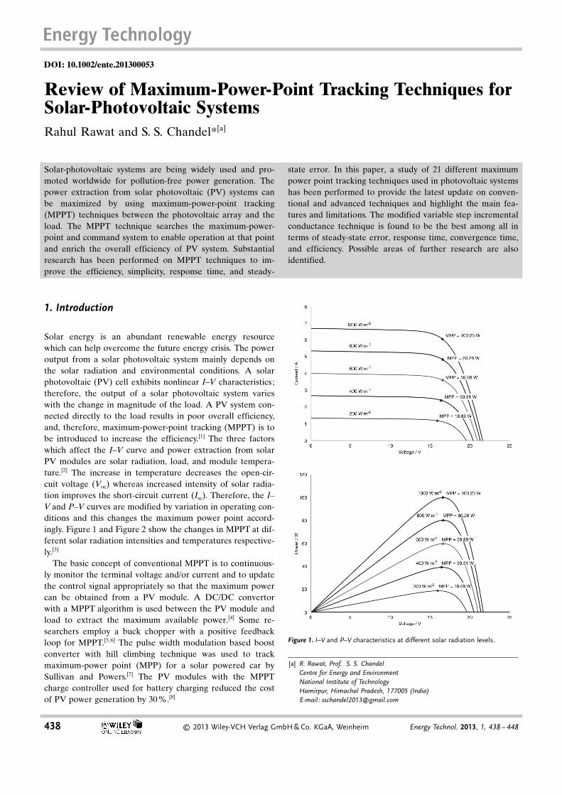
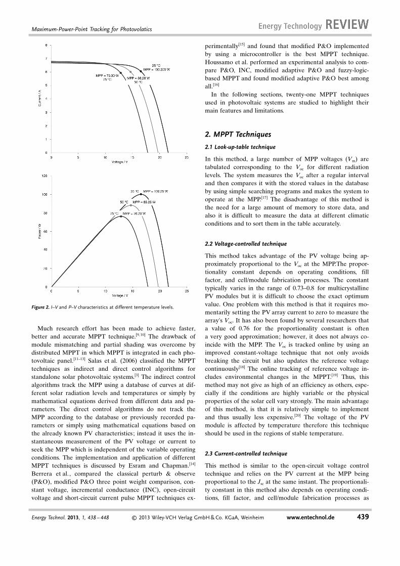
Solar energy is an abundant renewable energy resourcewhich can help overcome the future energy crisis. The poweroutput from a solar photovoltaic system mainly depends onthe solar radiation and environmental conditions. A solarphotovoltaic (PV) cell exhibits nonlinear I–V characteristics;therefore, the output of a solar photovoltaic system varieswith the change in magnitude of the load. A PV system con-nected directly to the load results in poor overall efficiency,and, therefore, maximum-power-point tracking (MPPT) is tobe introduced to increase the efficiency.[1] The three factorswhich affect the I–V curve and power extraction from solarPV modules are solar radiation, load, and module tempera-ture.[2] The increase in temperature decreases the open-cir-cuit voltage (Voc) whereas increased intensity of solar radia-tion improves the short-circuit current (Isc). Therefore, the I–V and P–V curves are modified by variation in operating con-ditions and this changes the maximum power point accord-ingly. Figure 1 and Figure 2 show the changes in MPPT at dif-ferent solar radiation intensities and temperatures respective-ly.[3]
The basic concept of conventional MPPT is to continuous-ly monitor the terminal voltage and/or current and to updatethe control signal appropriately so that the maximum powercan be obtained from a PV module. A DC/DC convertorwith a MPPT algorithm is used between the PV module andload to extract the maximum available power.[4] Some re-searchers employ a buck chopper with a positive feedbackloop for MPPT.[5,6] The pulse width modulation based boostconverter with hill climbing technique was used to trackmaximum-power point (MPP) for a solar powered car bySullivan and Powers.[7] The PV modules with the MPPTcharge controller used for battery charging reduced the costof PV power generation by 30 %.[8]
Solar-photovoltaic systems are being widely used and pro-moted worldwide for pollution-free power generation. Thepower extraction from solar photovoltaic (PV) systems canbe maximized by using maximum-power-point tracking(MPPT) techniques between the photovoltaic array and theload. The MPPT technique searches the maximum-power-point and command system to enable operation at that pointand enrich the overall efficiency of PV system. Substantialresearch has been performed on MPPT techniques to im-prove the efficiency, simplicity, response time, and steady-
state error. In this paper, a study of 21 different maximumpower point tracking techniques used in photovoltaic systemshas been performed to provide the latest update on conven-tional and advanced techniques and highlight the main fea-tures and limitations. The modified variable step incrementalconductance technique is found to be the best among all interms of steady-state error, response time, convergence time,and efficiency. Possible areas of further research are alsoidentified.
Figure 1. I–V and P–V characteristics at different solar radiation levels.
[a] R. Rawat, Prof. S. S. ChandelCentre for Energy and EnvironmentNational Institute of TechnologyHamirpur, Himachal Pradesh, 177005 (India)E-mail: [email protected]
438 � 2013 Wiley-VCH Verlag GmbH & Co. KGaA, Weinheim Energy Technol. 2013, 1, 438 – 448
Much research effort has been made to achieve faster,better and accurate MPPT technique.[9,10] The drawback ofmodule mismatching and partial shading was overcome bydistributed MPPT in which MPPT is integrated in each pho-tovoltaic panel.[11–13] Salas et al. (2006) classified the MPPTtechniques as indirect and direct control algorithms forstandalone solar photovoltaic systems.[3] The indirect controlalgorithms track the MPP using a database of curves at dif-ferent solar radiation levels and temperatures or simply bymathematical equations derived from different data and pa-rameters. The direct control algorithms do not track theMPP according to the database or previously recorded pa-rameters or simply using mathematical equations based onthe already known PV characteristics ; instead it uses the in-stantaneous measurement of the PV voltage or current toseek the MPP which is independent of the variable operatingconditions. The implementation and application of differentMPPT techniques is discussed by Esram and Chapman.[14]
Berrera et al. , compared the classical perturb & observe(P&O), modified P&O three point weight comparison, con-stant voltage, incremental conductance (INC), open-circuitvoltage and short-circuit current pulse MPPT techniques ex-
perimentally[15] and found that modified P&O implementedby using a microcontroller is the best MPPT technique.Houssamo et al. performed an experimental analysis to com-pare P&O, INC, modified adaptive P&O and fuzzy-logic-based MPPT and found modified adaptive P&O best amongall.[16]
In the following sections, twenty-one MPPT techniquesused in photovoltaic systems are studied to highlight theirmain features and limitations.
2. MPPT Techniques
2.1 Look-up-table technique
In this method, a large number of MPP voltages (Vm) aretabulated corresponding to the Voc for different radiationlevels. The system measures the Voc after a regular intervaland then compares it with the stored values in the databaseby using simple searching programs and makes the system tooperate at the MPP.[17] The disadvantage of this method isthe need for a large amount of memory to store data, andalso it is difficult to measure the data at different climaticconditions and to sort them in the table accurately.
2.2 Voltage-controlled technique
This method takes advantage of the PV voltage being ap-proximately proportional to the Voc at the MPP.The propor-tionality constant depends on operating conditions, fillfactor, and cell/module fabrication processes. The constanttypically varies in the range of 0.73–0.8 for multicrystallinePV modules but it is difficult to choose the exact optimumvalue. One problem with this method is that it requires mo-mentarily setting the PV array current to zero to measure thearray’s Voc. It has also been found by several researchers thata value of 0.76 for the proportionality constant is oftena very good approximation; however, it does not always co-incide with the MPP. The Voc is tracked online by using animproved constant-voltage technique that not only avoidsbreaking the circuit but also updates the reference voltagecontinuously[18] The online tracking of reference voltage in-cludes environmental changes in the MPPT.[19] Thus, thismethod may not give as high of an efficiency as others, espe-cially if the conditions are highly variable or the physicalproperties of the solar cell vary strongly. The main advantageof this method, is that it is relatively simple to implementand thus usually less expensive.[20] The voltage of the PVmodule is affected by temperature therefore this techniqueshould be used in the regions of stable temperature.
2.3 Current-controlled technique
This method is similar to the open-circuit voltage controltechnique and relies on the PV current at the MPP beingproportional to the Jsc at the same instant. The proportionali-ty constant in this method also depends on operating condi-tions, fill factor, and cell/module fabrication processes as
Figure 2. I–V and P–V characteristics at different temperature levels.
Energy Technol. 2013, 1, 438 – 448 � 2013 Wiley-VCH Verlag GmbH & Co. KGaA, Weinheim www.entechnol.de 439
Maximum-Power-Point Tracking for Photovolatics
with the voltage-controlled method, and its typical value formulticrystalline PV module is about 0.85. Noguchi et al. esti-mated the proportionality constant for varying temperatureand solar radiation to be approximately 0.92.[21]
The current-controlled MPPT (CCMPPT) is more sensi-tive than the voltage-controlled MPPT (VCMPPT) in choos-ing appropriate step size because of the confined range ofthe Jsc.
[22] The implementation of the CCMPPT circuit ismore complicated and costly than the VCMPPT.
2.4 Equation-based technique
The equation-based technique finds the MPP by differentiat-ing the power equation of the PV module with respect tovoltage or current and equating it to zero.[23] This techniqueis based on a MPPT equation which uses the Jsc and Voc asinputs to track the MPP and does not need to measure thetemperature. The approximate current output of a SPVmodule is given by Equation (1) which can be rewritten asEquation (2) for calculating output voltage.[24]
Ipv ¼ Isc � I0ekVpv ð1Þ
Vpv ¼1k
lnIsc � Ipv
I0
� �ð2Þ
in which Ipv is the output current, Vpv is the output voltage, I0
is the dark saturation current, Isc is the short-circuit current,and k is a constant that depends on the temperature andseries resistance of the SPV module. The power output(Ppv = Ipv �Vpv) is given by Equation (3).
Ppv ¼1k� Ipv � ln
Isc � Ipv
I0
� �ð3Þ
Equation (3) is differentiated with respect to Ipv and thenequated to zero to find the current output at the MPP (Imp)as given in Equation (4):
dPpv
dIpv¼ 1
kln
Isc � Ipv
I0
� �� 1
kIpv
Isc � Ipv
� �¼ 0 ð4Þ
The Ipv is the maximum output current for Equation (4) andcan be written as the output current at the MPP (Imp). TheIpv is substituted with Imp in Equation (4) and rearranged asthe MPP equation, given by Equation (5):
Imp ¼ Isc � Imp
� �ln
Isc � Imp
I0
� �ð5Þ
The dark saturation current (I0) of the SPV module is calcu-lated and the MPP equation is modified to give Equa-tion (6):
Imp ¼ Isc � Imp
� �ln Isc � Imp
� �þ ln Að Þ
þC a
VOC;k�VOC;rþaTr
� �
�3 ln VOC;k�VOC;r
a þ Tr
� �
266664
377775 ð6Þ
where Voc,k is the open-circuit voltage at instant k, Voc,r is therated open circuit voltage, Tr is the reference temperature(25 8C), a is the temperature coefficient of voltage, and Aand C are constants.
The modeling-equation-based MPPT was proposed by Vi-torino et al.[25] and it includes the temperature effects on thePV module without requiring the measurement of the solarradiation. The equation-based MPPT was designed and ana-lyzed by Dallago et al.[26] and employs a second-order deriva-tive of the noisy sampled output voltage.
A large memory requirement for solving mathematicalequations along with typicall insufficient knowledge of thecell material and module manufacturing details are some ofthe disadvantages associated with this method. The advantag-es include being simple to implement. Furthermore, theproblem faced in this technique during the real-time imple-mentation is the time-consuming operation of solving equa-tions while the MPP is varying rapidly under variable envi-ronmental conditions.
2.5 Hill-climbing techniques
The shape of the P–V curve can be thought of as hill-shaped,and the MPP is on the top of the hill. Therefore, the hill-climbing-based techniques are so named because these tech-niques attain the MPP by bit-by-bit tracking. These tech-niques include the perturb & observe algorithm (P&O) andincremental conductance algorithm (INC).
The efficiencies of the P&O and INC algorithms are96.5 % and 98.2 %, respectively.[27] The average increase inenergy extraction is found to be in the range of 16–43 % byusing conventional hill-climbing MPPT.[28] These techniquesare explained in following sections.
2.5.1 Perturb & observe technique
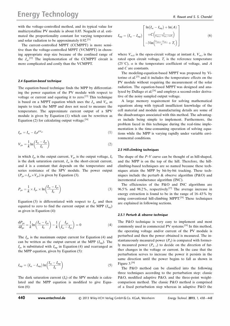
The P&O technique is very easy to implement and mostcommonly used in commercial PV systems.[29] In this method,the operating voltage and/or current of the PV module isperturbed and then the power obtained is measured. The in-stantaneously measured power (Pk) is compared with former-ly measured power (Pk�1) to decide on the direction of fur-ther changes in the voltage or current. In the case that theperturbation serves to increase the power it persists in thesame direction until the power begins to fall as shown inFigure 3.[30]
The P&O method can be classified into the followingthree techniques according to the perturbation step: classicP&O, modified adaptive P&O, and the three-point weight-comparison method. The classic P&O method is comprisedof a fixed perturbation step whereas in adaptive P&O the
440 www.entechnol.de � 2013 Wiley-VCH Verlag GmbH & Co. KGaA, Weinheim Energy Technol. 2013, 1, 438 – 448
R. Rawat and S. S. Chandel
step size changes according to the distance of the operatingpoint from the MPP. The modified adaptive P&O is ex-plained in the subsection 2.5.2. The three-point weight com-parison method selects the direction of perturbation accord-ing to the result of the power output at three different pointson the PV curve.[31]
According to the perturbing parameter, the P&O methodis classified into three techniques that is, reference voltageperturbation, reference current perturbation and duty ratioperturbation. Reference voltage perturbation P&O is fast re-sponding with energy utilization efficiencies of 97 and97.2 %, respectively, for rapidly and slowly varying solar radi-ation levels, whereas the energy utilization efficiencies ofduty ratio perturbation P&O are 97.9 and 99 % for rapidlyand slowly changing irradiance levels.[32]
The sampling frequency of the P&O algorithm is eithersimply increased or optimized to improve the robustness ofthe algorithm. In the optimized P&O method the perturba-tion step size and sampling interval are optimized accordingto the dynamic behavior of the entire system.[33,34] The per-turbation step size and time step are optimized and calculat-ed for efficient MPPT.[35,36] A digital signal processing basedcontroller is incorporated to track multiple peak-powerpoints in the solar array and to reduce the power loss in thetracking process.[37–40] For grid-connected photovoltaics, ananalog control network operates on the error signal generat-ed from the measured and reference signals to remove theoscillation caused by low-frequency disturbances comingfrom the grid.[41] Kumar and Gupta, proposed an extendedP&O technique, in which the MPP is converged using theconventional P&O technique then the PV voltage is main-
tained at the MPP by regulating the duty cycle on the basisof the difference between the MPP voltage (Vmpp) and in-stantaneous PV voltage (Vpv) at regular intervals.[42]
The major disadvantage of this technique is that it mainlyoscillates around the MPP at lower solar-radiation levels andis confounded during partially cloudy days. Therefore, thistechnique should be implemented in the locations wherecloudy days are infrequent.
2.5.2 Modified adaptive P&O method
If the step size is too small, the MPPT will respond slowlyunder rapidly varying operating conditions but it will givebetter results under stable conditions. With larger step sizes,the MPPT will respond quickly to the frequent changes butthe steady-state error increases. Therefore, the step size isa very important parameter for hill-climbing MPPT tech-niques and it should be either optimized or we can usea more-complicated but more-efficient adaptive step size hillclimbing algorithm.[13,43]
During cloudy weather, rapidly varying solar radiationconfuses the hill climbing as well as adaptive hill climbing al-gorithms for tracking the MPP. Moreover, the constant stepsize of the duty cycle is also a major problem in the hill-climbing algorithm; a small step size makes the algorithmslow and a large step size leads to large output power fluctu-ation resulting in a lower average output power. Therefore,the step size a should be large during transient change ofsolar radiation, and it should be small during steady-state op-eration. Therefore, a combination of two step sizes can beused depending on the power threshold value. A small stepsize is used if the power difference is less than the thresholdvalue and a larger step size is applied if power difference ismore than the threshold value.[44]
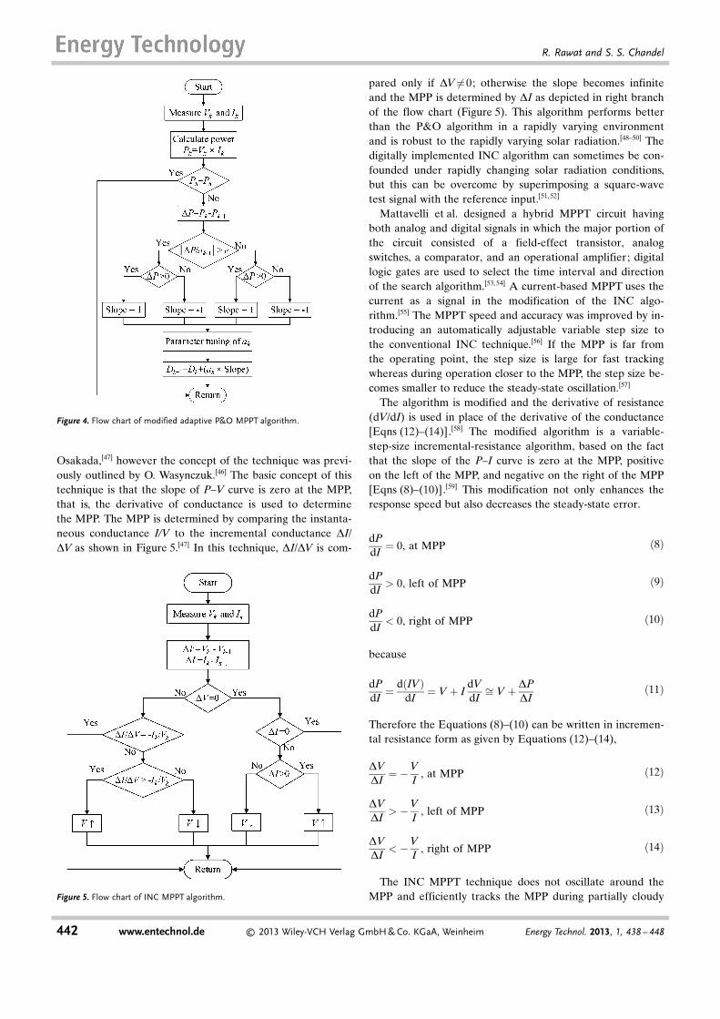
The modified adaptive P&O is the best MPPT techniqueamong all hill-climbing techniques and its implementation isperformed by using a microcontroller.[15] In the modifiedadaptive P&O MPPT technique, the automatic tuning ofstep size a removes a drawback of the P&O technique. Theparameter a is controlled by Equation (7). The duty cycle isadjusted according to the change in power (DP) if the valueof jDP/ak�1 j is greater than the threshold value e as shown inFigure 4. If the value of jDP/ak�1 j is less than e, the step sizea is large [Eq. (7)]. The step size of the adaptive P&O tech-nique can be updated by fuzzy-logic control to decrease therate of the oscillation.[45]
a tð Þ ¼MDPj j
a t � 1ð Þ ð7Þ
in which DP=P(t)�P(t�1) and M= constant parameter.
2.5.3 Incremental conductance technique
The incremental conductance (INC) technique of MPPT wasdeveloped by K. H. Hussein, I. Muta, T. Hoshino, and M.
Figure 3. Flow chart of P&O algorithm.
Energy Technol. 2013, 1, 438 – 448 � 2013 Wiley-VCH Verlag GmbH & Co. KGaA, Weinheim www.entechnol.de 441
Maximum-Power-Point Tracking for Photovolatics
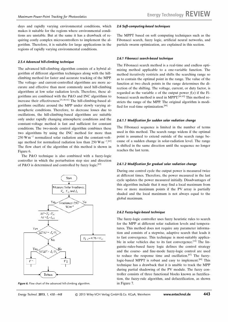
Osakada,[47] however the concept of the technique was previ-ously outlined by O. Wasynczuk.[46] The basic concept of thistechnique is that the slope of P–V curve is zero at the MPP,that is, the derivative of conductance is used to determinethe MPP. The MPP is determined by comparing the instanta-neous conductance I/V to the incremental conductance DI/DV as shown in Figure 5.[47] In this technique, DI/DV is com-
pared only if DV¼6 0; otherwise the slope becomes infiniteand the MPP is determined by DI as depicted in right branchof the flow chart (Figure 5). This algorithm performs betterthan the P&O algorithm in a rapidly varying environmentand is robust to the rapidly varying solar radiation.[48–50] Thedigitally implemented INC algorithm can sometimes be con-founded under rapidly changing solar radiation conditions,but this can be overcome by superimposing a square-wavetest signal with the reference input.[51, 52]
Mattavelli et al. designed a hybrid MPPT circuit havingboth analog and digital signals in which the major portion ofthe circuit consisted of a field-effect transistor, analogswitches, a comparator, and an operational amplifier; digitallogic gates are used to select the time interval and directionof the search algorithm.[53,54] A current-based MPPT uses thecurrent as a signal in the modification of the INC algo-rithm.[55] The MPPT speed and accuracy was improved by in-troducing an automatically adjustable variable step size tothe conventional INC technique.[56] If the MPP is far fromthe operating point, the step size is large for fast trackingwhereas during operation closer to the MPP, the step size be-comes smaller to reduce the steady-state oscillation.[57]
The algorithm is modified and the derivative of resistance(dV/dI) is used in place of the derivative of the conductance[Eqns (12)–(14)].[58] The modified algorithm is a variable-step-size incremental-resistance algorithm, based on the factthat the slope of the P–I curve is zero at the MPP, positiveon the left of the MPP, and negative on the right of the MPP[Eqns (8)–(10)].[59] This modification not only enhances theresponse speed but also decreases the steady-state error.
dPdI¼ 0, at MPP ð8Þ
dPdI
> 0, left of MPP ð9Þ
dPdI
< 0, right of MPP ð10Þ
because
dPdI¼ d IVð Þ
dI¼ V þ I
dVdIffi V þ DP
DIð11Þ
Therefore the Equations (8)–(10) can be written in incremen-tal resistance form as given by Equations (12)–(14),
DVDI¼ �V
I, at MPP ð12Þ
DVDI
> �VI
, left of MPP ð13Þ
DVDI
< �VI
, right of MPP ð14Þ
The INC MPPT technique does not oscillate around theMPP and efficiently tracks the MPP during partially cloudy
Figure 4. Flow chart of modified adaptive P&O MPPT algorithm.
Figure 5. Flow chart of INC MPPT algorithm.
442 www.entechnol.de � 2013 Wiley-VCH Verlag GmbH & Co. KGaA, Weinheim Energy Technol. 2013, 1, 438 – 448
R. Rawat and S. S. Chandel
days and rapidly varying environmental conditions, whichmakes it suitable for the regions where environmental condi-tions are unstable. But at the same it has a drawback of re-quiring costly complex microcontrollers to implement the al-gorithm. Therefore, it is suitable for large applications in theregions of rapidly varying environmental conditions.
2.5.4 Advanced hill-climbing technique
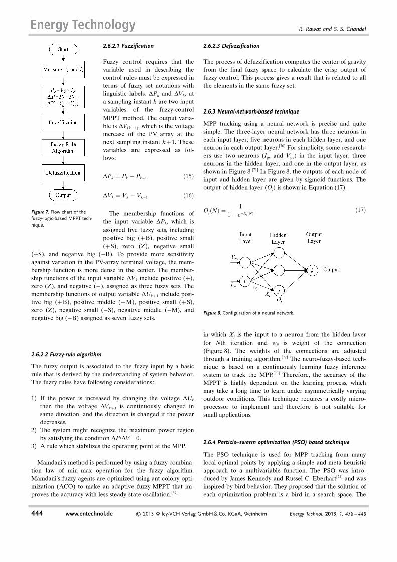
The advanced hill-climbing algorithm consists of a hybrid al-gorithm of different algorithm techniques along with the hill-climbing method for faster and accurate tracking of the MPP.The voltage- and current-controlled algorithms are more ac-curate and effective than most commonly used hill-climbingalgorithms at low solar radiation levels. Therefore, these al-gorithms are combined with the P&O and INC algorithms toincrease their effectiveness.[31,60,61] The hill-climbing-based al-gorithms oscillate around the MPP under slowly varying at-mospheric conditions. Therefore, to decrease losses due tooscillations, the hill-climbing-based algorithms are suitableonly under rapidly changing atmospheric conditions and theconstant-voltage method is fast and sufficient for constantconditions. The two-mode control algorithm combines thesetwo algorithms by using the INC method for more than250 W m�2 normalized solar radiation and the constant-volt-age method for normalized radiation less than 250 W m�2.[62]
The flow chart of the algorithm of this method is shown inFigure 6.
The P&O technique is also combined with a fuzzy-logiccontroller in which the perturbation step size and directionof P&O is determined and controlled by fuzzy logic.[63]
2.6 Soft-computing-based techniques
The MPPT based on soft computing techniques such as theFibonacci search, fuzzy logic, artificial neural networks, andparticle swarm optimization, are explained in this section.
2.6.1 Fibonacci search-based technique
The Fibonacci search method is a real-time and endless opti-mizing method applicable to a one-variable function. Themethod iteratively restricts and shifts the searching range soas to contain the optimal point in the range. The value of thefunction at two check points in the range determines the di-rection of the shifting. The voltage, current, or duty factor, isregarded as the variable x of the output power f(x) if the Fi-bonacci search method is used in MPPT.[64, 65] This method re-stricts the range of the MPP. The original algorithm is modi-fied for real-time optimization.[66]
2.6.1.1 Modification for sudden solar radiation change
The Fibonacci sequence is limited in the number of termsused in this method. The search range widens if the optimalpoint is assumed to extend outside of the search range be-cause of a sudden change in solar-radiation level. The rangeis shifted in the same direction until the sequence no longerreaches the last term.
2.6.1.2 Modification for gradual solar radiation change
During one control cycle the output power is measured twiceat different times. Therefore, the power measured in the lastcycle updates the power measured initially. Disadvantages ofthis algorithm include that it may find a local maximum fromtwo or more maximum points if the PV array is partiallyshaded and the local maximum is not always equal to theglobal maximum.
2.6.2 Fuzzy-logic-based technique
The fuzzy-logic controller uses fuzzy heuristic rules to searchfor the MPP at different solar radiation levels and tempera-tures. This method does not require any parameter informa-tion and consists of a stepwise, adaptive search that leads itto fast convergence. This technique is most-suitably applica-ble in solar vehicles due to its fast convergence.[14] The lin-guistic-rules-based fuzzy logic defines the control strategyand the coarse- and fine-mode fuzzy-logic control are usedto reduce the response time and oscillation.[67] The fuzzy-logic-based MPPT is robust and easy to implement.[68] Thistechnique has a drawback that it is unable to track the MPPduring partial shadowing of the PV module. The fuzzy con-troller consists of three functional blocks known as fuzzifica-tion, the fuzzy-rule algorithm, and defuzzification, as shownin Figure 7.Figure 6. Flow chart of the advanced hill-climbing algorithm.
Energy Technol. 2013, 1, 438 – 448 � 2013 Wiley-VCH Verlag GmbH & Co. KGaA, Weinheim www.entechnol.de 443
Maximum-Power-Point Tracking for Photovolatics
2.6.2.1 Fuzzification
Fuzzy control requires that thevariable used in describing thecontrol rules must be expressed interms of fuzzy set notations withlinguistic labels. DPk and DVk, ata sampling instant k are two inputvariables of the fuzzy-controlMPPT method. The output varia-ble is DV(k+1), which is the voltageincrease of the PV array at thenext sampling instant k+1. Thesevariables are expressed as fol-lows:
DPk ¼ Pk � Pk�1 ð15Þ
DVk ¼ Vk � Vk�1 ð16Þ
The membership functions ofthe input variable DPk, which isassigned five fuzzy sets, includingpositive big (+B), positive small(+S), zero (Z), negative small
(�S), and negative big (�B). To provide more sensitivityagainst variation in the PV-array terminal voltage, the mem-bership function is more dense in the center. The member-ship functions of the input variable DVk include positive (+),zero (Z), and negative (�), assigned as three fuzzy sets. Themembership functions of output variable DUk+ 1 include posi-tive big (+ B), positive middle (+M), positive small (+ S),zero (Z), negative small (�S), negative middle (�M), andnegative big (�B) assigned as seven fuzzy sets.
2.6.2.2 Fuzzy-rule algorithm
The fuzzy output is associated to the fuzzy input by a basicrule that is derived by the understanding of system behavior.The fuzzy rules have following considerations:
1) If the power is increased by changing the voltage DUk
then the the voltage DVk+ 1 is continuously changed insame direction, and the direction is changed if the powerdecreases.
2) The system might recognize the maximum power regionby satisfying the condition DP/DV= 0.
3) A rule which stabilizes the operating point at the MPP.
Mamdani’s method is performed by using a fuzzy combina-tion law of min–max operation for the fuzzy algorithm.Mamdani’s fuzzy agents are optimized using ant colony opti-mization (ACO) to make an adaptive fuzzy-MPPT that im-proves the accuracy with less steady-state oscillation.[69]
2.6.2.3 Defuzzification
The process of defuzzification computes the center of gravityfrom the final fuzzy space to calculate the crisp output offuzzy control. This process gives a result that is related to allthe elements in the same fuzzy set.
2.6.3 Neural-network-based technique
MPP tracking using a neural network is precise and quitesimple. The three-layer neural network has three neurons ineach input layer, five neurons in each hidden layer, and oneneuron in each output layer.[70] For simplicity, some research-ers use two neurons (Ipv and Vpv) in the input layer, threeneurons in the hidden layer, and one in the output layer, asshown in Figure 8.[71] In Figure 8, the outputs of each node ofinput and hidden layer are given by sigmoid functions. Theoutput of hidden layer (Oj) is shown in Equation (17).
Oj Nð Þ ¼ 11� e�Xj Nð Þ
ð17Þ
in which Xj is the input to a neuron from the hidden layerfor Nth iteration and wji is weight of the connection(Figure 8). The weights of the connections are adjustedthrough a training algorithm.[72] The neuro-fuzzy-based tech-nique is based on a continuously learning fuzzy inferencesystem to track the MPP.[73] Therefore, the accuracy of theMPPT is highly dependent on the learning process, whichmay take a long time to learn under asymmetrically varyingoutdoor conditions. This technique requires a costly micro-processor to implement and therefore is not suitable forsmall applications.
2.6.4 Particle–swarm optimization (PSO) based technique
The PSO technique is used for MPP tracking from manylocal optimal points by applying a simple and meta-heuristicapproach to a multivariable function. The PSO was intro-duced by James Kennedy and Russel C. Eberhart[74] and wasinspired by bird behavior. They proposed that the solution ofeach optimization problem is a bird in a search space. The
Figure 7. Flow chart of thefuzzy-logic-based MPPT tech-nique.
Figure 8. Configuration of a neural network.
444 www.entechnol.de � 2013 Wiley-VCH Verlag GmbH & Co. KGaA, Weinheim Energy Technol. 2013, 1, 438 – 448
R. Rawat and S. S. Chandel
bird is treated as a particle having a certain position and ve-locity that determines its movement and direction. The parti-cle will search two extreme positions to renew its old posi-tion during each iteration; one will be guided by particleitself and other position will be guided by the entireswarm.[74] The velocity vi and position xi of particle are ex-pressed as:
vtþ1i ¼ vt
i þ c1r1 pi � xti
� �þ c2r2 gi � xt
i
� �ð18Þ
xtþ1i ¼ xt
i þ vti ð19Þ
Shi and Aberhart modified the PSO and included a mo-mentum coefficient (w) in the former expression to optimizethe iteration speed.[75] The value of w varies in the range of0–1 depending on the number of iterations. The modified ex-pression is
vtþ1i ¼ wvt
i þ c1r1 pi � xti
� �þ c2r2 gi � xt
i
� �ð20Þ
A number of co-operative agents (particles) are used,which get the information from their respective search pro-cesses and then exchange this information with each other.The PSO technique is an intelligent technique for finding theglobal optimum solution of the MPP by only tuning a fewparameters.[76] The movement of these agents in the searchspace depends on two main factors:
* The previous best position of the agent* The previous best position among all agents
The dependence on the other agents decreases with the in-crease in number of iterations making the agent intelligentby utilizing a continuous learning process.[77] The PSO algo-rithm is modified by including the reinitialization of agentsto search for the MPP in the case of sudden changes in solarradiation or load.[78] If the PSO method of MPPT is appliedto two series-connected PV modules, of which one module ispartially shaded, having different terminal voltages V1 andV2, then the MPPT tracking becomes multidimensional andmultivariable.[79] In general, for N modules with N differentterminal voltages, there will be N variables to be controlledfor MPPT tracking. In this method, an N-Dimensional arrayis formed by the grouping of the individual terminal voltages.The PSO technique is modified to reduce the oscillation atthe MPP to almost zero by using direct-duty-cycle control intwo phases.[80] This technique is highly efficient under partial-ly shaded conditions.
2.6.5 Orthogonal particle swarm optimization
Orthogonal particle swarm optimization (OPSO) combinesan orthogonal array with the PSO technique to speed up thesearch for the optimal point.[81] This method includes the Ta-guchi method, which is based on experimental design, usedto evaluate appropriate orthogonal array.[82] The partial fac-torial method is used instead of the full factorial method in
orthogonal arrays to improve the conventional PSO tech-nique. The OPSO method has better searching capabilitywith a rapid convergence rate. It is composed of two factors:individual particle swarm (Oid) and group particle swarm(Aid).
Oid ¼ Xnid þWVn
id þ c1 � randð Þ � Ppd �Xnid
� �ð21Þ
Aid ¼ Xnid þWVn
id þ c2 � randð Þ � Pgd �Xnid
� �ð22Þ
The optimal solution for the above two factors can beevaluated by using an orthogonal array and is used for re-
freshing the particle position andvelocity. The algorithm is illustrat-ed in Figure 9.
2.6.6 Combined fuzzy logic andPSO technique
A new MPPT control method isdeveloped by combining the exist-ing fuzzy logic and particle–swarm optimization techniquesfor a fast response without oscilla-tion.[83]
In this technique the modifiedPSO expression given in Equa-tion (20) is used for tracking theMPP and the momentum coeffi-cient (w) in the formula is con-trolled by fuzzy logic. The w in-fluences the velocity of the parti-cle, therefore, the response speedof technique is controlled by ad-justing the value of the momen-tum coefficient dynamically usingthe fuzzy-logic control method.By this method, the position (xi)is adjusted faster when the MPPis far away and xi is adjusted slowly near the MPP. Thus, thistechnique is termed as a particle–swarm optimization algo-rithm based on fuzzy-logic control. This MPP technique isfaster and more accurate, but the fuzzy rule sets are influ-enced by some environmental factors, which imparts difficul-ty in making a fuzzy control table for different outdoor con-ditions.
2.7 Other MPPT techniques
The other MPPT techniques found in literature are summar-ized in this section. ripple-correlation-control (RCC)-basedMPPT makes use of ripples present in converter as dynamicperturbations. The correlation between power and voltage/current ripple is used to track maximum power point.[84]Theproduct of the time derivative of the power and voltageshould be zero for maximum power extraction. The RCC ismore effective for a distributed MPPT system in which each
Figure 9. Flow chart of theOPSO-based MPPT algorithm.
Energy Technol. 2013, 1, 438 – 448 � 2013 Wiley-VCH Verlag GmbH & Co. KGaA, Weinheim www.entechnol.de 445
Maximum-Power-Point Tracking for Photovolatics
PV module is connected with a separate MPPT.[85] The RCC-MPPT is not affected by the parasitic components present inPV arrays.[86] However, further research shows that it is nega-tively affected by the parasitic components if the DC/DCconverter is operated at high frequency.[87]
The extreme-seeking control (ESC) method introduces a si-nusoidal perturbation signal tothe reference current and uti-lizes the natural ripple pro-duced in the inverter to trackthe MPP. The ESC algorithm isimproved by using a variablestep size.[88]
The dual-module-basedMPPT shares the voltage andcurrent information of twoidentical modules.[89] The volt-age of one module is changedto a factor of other module�svoltage and then the poweroutput is compared. The factorconstant is changed accordinglyto reach the MPP.
The prediction-data-basedMPPT techniques depend onestablishing a prediction linebased on the linear relationshipbetween the maximum poweroutputs and then optimizing thecurrent.[90] The operating pointof the solar array is forced tofollow the prediction line.
The ACO method is a heuris-tic approach which creates vir-tual ants at different regionsrandomly throughout the entirespace and then the next regionis determined by shifting the probability until it reaches theoptimal solution. The ACO is combined with fuzzy controlto increase tracking efficiency.[91]
The beta technique employs an intermediate variable (b)of the photovoltaic that depends on the electrical parametersof the PV array: the voltage and the current.[92] The constantc in Equation (23) depends on the Boltzmann constant, tem-perature, the number of PV cells in the array, the electroniccharge, and the junction quality factor. This method offersmuch less voltage ripple during steady-state operation alongwith average transient performance.
b ¼ lnIpv
Vpv
� �� c� Vpv ð23Þ
The genetic-algorithm (GA)-based MPPT technique em-ploys a heuristic search to find the MPP. A reference voltageis generated to perturb and used in a heuristic search processuntil it reaches the MPP. Then, the output voltage, current,temperature, and solar radiation are measured at regular in-
tervals and the reference voltage is changed if there is anychange in temperature, solar radiation, or power output.[93]
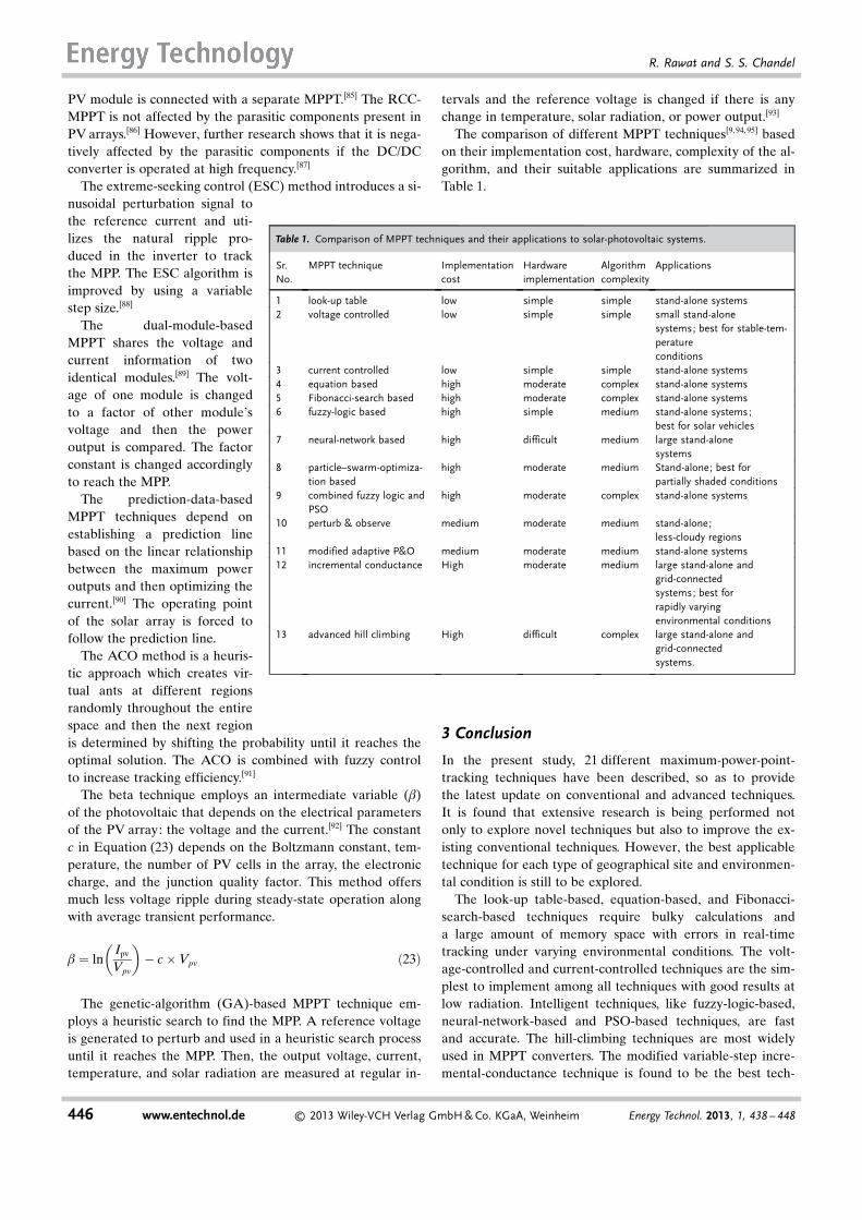
The comparison of different MPPT techniques[9,94,95] basedon their implementation cost, hardware, complexity of the al-gorithm, and their suitable applications are summarized inTable 1.
3 Conclusion
In the present study, 21 different maximum-power-point-tracking techniques have been described, so as to providethe latest update on conventional and advanced techniques.It is found that extensive research is being performed notonly to explore novel techniques but also to improve the ex-isting conventional techniques. However, the best applicabletechnique for each type of geographical site and environmen-tal condition is still to be explored.
The look-up table-based, equation-based, and Fibonacci-search-based techniques require bulky calculations anda large amount of memory space with errors in real-timetracking under varying environmental conditions. The volt-age-controlled and current-controlled techniques are the sim-plest to implement among all techniques with good results atlow radiation. Intelligent techniques, like fuzzy-logic-based,neural-network-based and PSO-based techniques, are fastand accurate. The hill-climbing techniques are most widelyused in MPPT converters. The modified variable-step incre-mental-conductance technique is found to be the best tech-
Table 1. Comparison of MPPT techniques and their applications to solar-photovoltaic systems.
Sr.No.
MPPT technique Implementationcost
Hardwareimplementation
Algorithmcomplexity
Applications
1 look-up table low simple simple stand-alone systems2 voltage controlled low simple simple small stand-alone
systems; best for stable-tem-peratureconditions
3 current controlled low simple simple stand-alone systems4 equation based high moderate complex stand-alone systems5 Fibonacci-search based high moderate complex stand-alone systems6 fuzzy-logic based high simple medium stand-alone systems;
best for solar vehicles7 neural-network based high difficult medium large stand-alone
systems8 particle–swarm-optimiza-
tion basedhigh moderate medium Stand-alone; best for
partially shaded conditions9 combined fuzzy logic and
PSOhigh moderate complex stand-alone systems
10 perturb & observe medium moderate medium stand-alone;less-cloudy regions
11 modified adaptive P&O medium moderate medium stand-alone systems12 incremental conductance High moderate medium large stand-alone and
grid-connectedsystems; best forrapidly varyingenvironmental conditions
13 advanced hill climbing High difficult complex large stand-alone andgrid-connectedsystems.
446 www.entechnol.de � 2013 Wiley-VCH Verlag GmbH & Co. KGaA, Weinheim Energy Technol. 2013, 1, 438 – 448
R. Rawat and S. S. Chandel
nique among all in the literature in terms of steady stateerror, response time, convergence time, and efficiency. Themodified-adaptive P&O is found to be best if compared onthe basis of cost, hardware requirements, and efficiency.
For further research, the MPPT techniques need to be im-plemented practically and tested for solar-photovoltaic sys-tems established at different locations under different envi-ronmental conditions to determine the performance and toidentify the appropriate MPPT technique for different envi-ronmental conditions.
Keywords: fuzzy logic · hill climbing techniques · neuralnetworks · optimization · solar cells
[1] A. F. Boehringer, IEEE Trans. Aerosp. Electron. Syst. 1968, AES-4,102 – 111.
[2] M. A. El-Shibini, H. H. Rakha, Electrotechnical Conferenc Proceed-ings: Integrating Research, Industry and Education in Energy andCommunication Engineering 1989, 21– 24.
[3] V. Salas, E. Olias, A. Barrado, A. Laizaro, Sol. Energy Mater. SolarCells 2006, 90, 1555 – 1578.
[4] H. S.-H. Chung, K. K. Tse, S. Y. Ron Hui, C. M. Mok, M. T. Ho,IEEE Trans. Power Elect. 2003, 18, 717 –724.
[5] E. Koutroulis, K. Kalaitzakis, N. C. Voulgaris, IEEE Trans. PowerElect. 2001, 16, 46 –54.
[6] J. Gonzalez-Llorente, E. I. Ortiz-Rivera, A. Diaz, IEEE InternationalElectric Machines and Drives Conference 2009, 259 –264.
[7] C. R. Sullivan, M. J. Powers, 24th Annual IEEE Power ElectronicsSpecialists Conference 1993, 574 –580.
[8] S. M. M. Wolf, J. H. R. Enslin, 24th Annual IEEE Power ElectronicsSpecialists Conference 1993, 581 –587.
[9] M. A. G. de Brito, L. Galotto, Jr., L. P. Sampaio, G. de Azevedo eMelo, C. A. Canesin, IEEE Trans. Ind. Electron. 2013, 60, 1156 –1167.
[10] A. Sayal, Pharmstudent Students Conference on Engineering and Sys-tems 2012, 1– 6.
[11] J. H. R. Enslin, M. S. Wolf, D. B. Snyman, W. Swiegers, IEEE Trans.Ind. Electron. 1997, 44, 769 – 773.
[12] N. Femia, G. Lisi, G. Petrone, G. Spagnuolo, M. Vitelli, IEEE Trans.Ind. Electron. 2008, 55, 2610 – 2621.
[13] Y. Jiang, J. A. Abu Qahouq, 27th Annual IEEE Applied Power Elec-tronics Conference and Exposition 2012, 1872 –1876.
[14] T. Esram, P. L. Chapman, IEEE Trans. Energy Convers. 2007, 22,439 – 449.
[15] M. Berrera, A. Dolara, R. Faranda, S. Leva, IEEE Bucharest PowerTech Conference 2009, 1 –8.
[16] I. Houssamo, F. Locment, M. Sechilariu, Int. J. Elec. Power EnergySyst. 2013, 46, 98– 107.
[17] H. E. A. Ibrahim, F. F. Houssiny, IEEE International Fuzzy SystemsConference Proceedings 1999, 406 –410.
[18] A. Tariq, M. S. J. Asgha, IEEE International Conference Power Elec-tronics and Drives Systems 2005, 251 – 255.
[19] A. W. Leedy, L. Guo, K. A. Aganah, Proceedings of IEEE Southeast-con 2012, 1 –6.
[20] M. A. S. Masoum, H. Dehbonei, E. F. Fuchs, IEEE Trans. EnergyConvers. 2002, 17, 514 –522.
[21] T. Noguchi, S. Togashi, R. Nakamoto, IEEE Trans. Ind. Electron.2002, 49, 217 –223.
[22] P. de Assis Sobreira, Jr., M. G. Villalva, P. G. Barbosa, H. A. C.Braga, J. R. Gazoli, E. Ruppert, A. A. Ferreira, IEEE Power Elec-tronics Conference 2011, 858 –863.
[23] M. Bodur, M. Ermis, 7th Mediterranean Electrotechnical ConferenceProceedings 1994, 758 –761.
[24] S. Yuvarajan, J. Shoeb, Third Annual IEEE Applied Power Electron-ics Conference and Exposition 2008, 167 –172.
[25] M. A. Vitorino, L. V. Hartmann, A. M. N. Lima, M. B. R. CorrÞa, Eu-ropean Conference on Power Electronics and Applications 2007, 1 –10.
[26] E. Dallago, D. G. Finarelli, U. P. Gianazza, A. L. Barnabei, A. Liber-ale, IEEE Trans. Power Electron. 2013, 28, 5088 –5097.
[27] D. P. Hohm, M. E. Ropp, Conference Record of the Twenty-EighthIEEE Photovoltaic Specialists Conference 2000, 1699 –1702.
[28] J. H. R. Enslin, 16th Annual Conference of IEEE Industrial Electron-ics Society 1990, 1073 –1077.
[29] J. A. B. Vieira, A. M. Mota, IEEE International Symposium on In-dustrial Electronics 2008, 202 –207.
[30] M. Veerachary, T. Senjyu, K. Uezato, IEEE Trans. Aerosp. Electron.Syst. 2002, 38, 262 – 270.
[31] R. Faranda, S. Leva, WSEAS Trans. Power Syst. 2008, 3, 446 – 455.[32] M. A. Elgendy, B. Zahawi, D. J. Atkinson, IEEE Trans. Sustainable
Energy 2012, 3, 21–33.[33] N. Femia, G. Petrone, G. Spagnuolo, M. Vitelli, IEEE International
Symposium on Industrial Electronics 2004, 2, 845 –850.[34] N. Femia, G. Petrone, G. Spagnuolo, M. Vitelli, IEEE Trans. Power
Electron. 2005, 20, 963 – 973.[35] A. Ahmed, L. Ran, J. Bumby, IEEE International Symposium on In-
dustrial Electronics 2012, 1819 –1824.[36] H. Radwan, M. Orabi, IEEE 34th International Telecommunications
Energy Conference 2012, 1 –7.[37] W. Wu, N. Pongratananukul, W. Qiu, K. Rustom, T. Kasparis, I. Ba-
tarseh, 18th Annual IEEE Applied Power Electronics Conference andExposition 2003, 1, 525 –530.
[38] C. Hua, J. Lin, C. Shen, IEEE Trans. Ind. Electron. 1998, 45, 99– 107.[39] C. Hua, C. Shen, 29th Annual IEEE Power Electronics Specialists
Conference Record 1998, 1, 86 –93.[40] C. Hua, J. Lin, Energy Convers. Manage. 2004, 45, 911 – 925.[41] N. Femia, G. Petrone, G. Spagnuolo, M. Vitelli, IEEE Trans. Ind.
Electron. 2009, 56, 4473 – 4482.[42] Y. S. Kumar, R. Gupta, Pharmstudent Students Conference on Engi-
neering and Systems 2012, 1– 6.[43] D. Sera, R. Teodorescu, J. Hantschel, M. Knoll, IEEE Trans. Ind.
Electron. 2008, 55, 2629 – 2637.[44] Y. Yang, F. Blaabjerg, 6th IET International Conference on Power
Electronics, Machines and Drives 2012, 1– 5.[45] A. Al Nabulsi, R. Dhaouadi, IEEE Trans. Ind. Inf. 2012, 8, 573 –584.[46] O. Wasynezuk, IEEE Trans. Power Appar. Syst. 1983, PAS-102,
3031 – 3037.[47] K. H. Hussein, I. Muta, T. Hoshino, M. Osakada, IEE Proc. Gener.
Transm. Distrib. 1995, 142, 59 –64.[48] I. Houssamo, F. Locment, M. Sechilariu, Renewable Energy 2010, 35,
2381 – 2387.[49] G. J. Kish, J. J. Lee, P. W. Lehn, IET Renewable Power Gener. 2012, 6,
259 – 266.[50] A. K. Singh, R. K. Tripathi, Pharmstudent Students Conference on
Engineering and Systems 2012, 1 –4.[51] T. Kim, H. Ahn, S. Park, Y. Lee, International Symposium on Indus-
trial Electronics 2001, 2, 1011 –1014.[52] W. J. A. Teulings, J. C. Marpinard, A. Capel, D. O’Sullivan, 24th
Annual IEEE Power Electronics Specialists Conference 1993, 833 –838.
[53] P. Mattavelli, S. Saggini, E. Orietti, G. Spiazzi, Twenty-Fifth AnnualIEEE Applied Power Electronics Conference and Exposition 2010,953 – 960.
[54] G. Spiazzi, S. Buso, P. Mattavelli, P. Tenti, The 2010 InternationalPower Electronics Conference 2010, 2074 –2081.
[55] H. Cha, S. Lee, IEEE Industry Applications Society Annual Meeting2008, 1 –5.
[56] F. Liu, S. Duan, F. Liu, B. Liu, Y. Kang, IEEE Trans. Ind. Electron.2008, 55, 958 –961.
[57] S. Rajasekar, R. Gupta, A. Upadhyay, P. Agarwal, S. Kumar, Y. S.Kumar, IEEE International Symposium on Industrial Electronics2012, 1801 – 1806.
[58] Q. Mei, M. Shan, L. Liu, J. M. Guerrero, IEEE Trans. Ind. Electron.2011, 58, 2427 –2434.
[59] S. Sreekanth, I. J. Raglend, International Conference on Computing,Electronics and Electrical Technologies 2012, 452 –456.
Energy Technol. 2013, 1, 438 – 448 � 2013 Wiley-VCH Verlag GmbH & Co. KGaA, Weinheim www.entechnol.de 447
Maximum-Power-Point Tracking for Photovolatics
[60] K. Irisawa, T. Saito, I. Takano, Y. Sawada, Conference Record of theTwenty-Eighth IEEE Photovoltaic Specialists Conference 2000, 1707 –1710.
[61] K. Kobayashi, I. Takano, Y. Sawada, Sol. Energy Mater. Sol. Cells2006, 90, 2975 –2988.
[62] G. J. Yu, Y. S. Jung, J. Y. Choi, G. S. Kim, Sol. Energy 2004, 76, 455 –463.
[63] W. Yang, Z. Yang, Y. Lee, C. Chen, J. Lai, IEEE 7th InternationalPower Electronics and Motion Control Conference 2012, 2056 –2060.
[64] M. Miyatake, M. T. Kouno, Motomu Nakano, International Confer-ence of Power Electronics 2001, 622 –625.
[65] M. Miyatake, T. Kouno, M. Nakano, EPE-PEMC2002, 2002, No. T6 –003.
[66] M. Miyatake, T. Inada, I. Hiratsuka, H. Zhao, H. Otsuka, M.Nakano, Power Electronics and Motion Control Conference 2004, 2,816 – 821.
[67] C. Won, D. Kim, S.-C. Kim, W.-S. Kim, H.-S. Kim, 25th AnnualIEEE Power Electronics Specialists Conference 1994, 1, 396 – 403.
[68] V. Padmanabhan, V. Beena, M. Jayaraju, International Conference onPower, Signals, Controls and Computation 2012, 1 –6.
[69] M. Adly, A. H. Besheer, 7th IEEE Conference on Industrial Electron-ics and Applications 2012, 113 – 119.
[70] T. Hiyama, S. Kouzuma, T. Imakubo, IEEE Trans. Energy Convers.1995, 10, 360 –367.
[71] M. Tsai, C. Tseng, G. Hong, S. Lin, IEEE International Symposiumon Industrial Electronics 2012, 1742 –1747.
[72] I. Cha, J. Choi, G. Yu, M. Jung, H. Baek, D. Kim, Conference Recordof the Twenty-Sixth IEEE Photovoltaic Specialists Conference 1997,1321 – 1324.
[73] F. Mayssa, L. Sbita, First International Conference on Renewable En-ergies and Vehicular Technology 2012, 167 –172.
[74] J. Kennedy, R. Eberhart, Proceedings of IEEE International Confer-ence on Neural Networks 1995, 1942 –1948.
[75] Y. Shi, R. Eberhart, Proceedings of IEEE World Congress on Com-putational Intelligence 1998, 69 –73.
[76] R. Suryavanshi, D. R. Joshi, S. H. Jangamshetti, 2012 InternationalConference on Power, Signals, Controls and Computation (EPSCI-CON) 2012, 1 –6.
[77] M. A. Azam, S. Abdullah-AI-Nahid, M. M. Alam, B. A. Plabon,IEEE/OSA/IAPR International Conference on Informatics, Electron-ics & Vision 2012, 292 –297.
[78] M. Miyatake, F. Toriumi, T. Endo, N. Fujii, European Conference onPower Electronics and Applications 2007, 1–10.
[79] M. Miyatake, M. Veerachary, F. Toriumi, N. Fujii, H. Ko, IEEETrans. Aerosp. Electron. Syst. 2011, 47, 367 –380.
[80] K. Ishaque, Z. Salam, M. Amjad, S. Mekhilef, IEEE Trans. PowerElectron. 2012, 27, 3627 – 3638.
[81] S.-Y. Ho, H.-S. Lin, W.-H. Liauh, S.-J. Ho, IEEE TSMC A 2008, 38,288 – 298.
[82] J.-L. Kuo, K.-L. Chao, L.-S. Lee, IEEE Trans. Ind. Electron. 2010, 57,678 – 689.
[83] Y. Hu, J. Liu, B. Liu, Second International Conference on IntelligentSystem Design and Engineering Application 2011, 73 –75.
[84] P. Midya, P. T. Krein, R. J. Turnbull, R. Reppa, J. Kimball, 27thAnnual IEEE Power Electronics Specialists Conference Record 1996,2, 1710 –1716.
[85] T. Esram, J. W. Kimball, P. T. Krein, P. L. Chapman, P. Midya, IEEETrans. Power Electron. 2006, 21, 1282 – 1291.
[86] A. Brambilla, M. Gambarara, A. Garutti, F. Ronchi, 30th AnnualIEEE Power Electronics Specialists Conference 1999, 2, 632 – 637.
[87] G. Spiazzi, S. Buso, P. Mattavelli, IEEE Power Electronics Confer-ence 2009, 88– 95.
[88] C. Zhang, Z. Zhang, M. Chen, Z. Qian, IEEE International Symposi-um on Industrial Electronics 2012, 1765 –1770.
[89] J.-H. Park, J.-Y. Ahn, B.-H. Cho, G.-J. Yu, IEEE Trans. Ind. Electron.2006, 53, 1036 –1047.
[90] N. Mutoh, T. Matuo, K. Okada, M. Sakai, IEEE 33rd Annual PowerElectronics Specialists Conference 2002, 3, 1489 –1494.
[91] Q. Fu, N. Tong, IEEE International Conference on Computer Scienceand Electronics Engineering 2012, 394 –398.
[92] S. Jain, V. Agarwal, IEEE Power Electron. Lett. 2004, 2, 16–19.[93] H. R. Mohajeri, M. P. Moghaddam, M. Shahparasti, M. Mohamadian,
20th Iranian Conference on Electrical Engineering 2012, 489 –494.[94] D. P. Hohm, M. E. Ropp, Prog. Photovoltaics 2003, 11, 47– 62.[95] Z. Salam, J. Ahmed, B. S. Merugu, Appl. Energy 2013, 107, 135 – 148.
Received: May 19, 2013Revised: June 15, 2013
448 www.entechnol.de � 2013 Wiley-VCH Verlag GmbH & Co. KGaA, Weinheim Energy Technol. 2013, 1, 438 – 448
R. Rawat and S. S. Chandel

![Optimised Photovoltaic Solar Charger With Voltage … · Optimised Photovoltaic Solar Charger With Voltage Maximum Power Point Tracking ... MPPT) [5]. The main goal of this thesis](https://img.pdfslide.net/doc/110x75/5b5c96607f8b9ac8618c8870/optimised-photovoltaic-solar-charger-with-voltage-optimised-photovoltaic-solar.jpg)