Embed Size (px)
Citation preview
TP-12126
Driveline Application GuidelinesRevised 01-17
Driveline Application Guidelines
Table of ContentsSection 1 – Notes . . . . . . . . . . . . . . . . . . . . . . . . . . . . . . . . . . . . . . . . . . . . . . . .1Purpose of These Guidelines . . . . . . . . . . . . . . . . . . . . . . . . . . . . . . . . . . . . . . . . . . . . . . . . . 1Changes to Guidelines . . . . . . . . . . . . . . . . . . . . . . . . . . . . . . . . . . . . . . . . . . . . . . . . . . . . . . 1Warranty . . . . . . . . . . . . . . . . . . . . . . . . . . . . . . . . . . . . . . . . . . . . . . . . . . . . . . . . . . . . . . . . . . 1Comparing Meritor's RPL Series Permalube™ and Xtended Lube MXL™ Series Drivelines . . . . . . . . . . . . . . . . . . . . . . . . . . . . . . . . . . . . . 1Notes . . . . . . . . . . . . . . . . . . . . . . . . . . . . . . . . . . . . . . . . . . . . . . . . . . . . . . . . . . . . . . . . . . . . . 1
Section 2 – Requirements. . . . . . . . . . . . . . . . . . . . . . . . . . . . . . . . . . . . . . . . . .3
Section 3 – Driveline Sizing Process . . . . . . . . . . . . . . . . . . . . . . . . . . . . . . . . .4Definitions . . . . . . . . . . . . . . . . . . . . . . . . . . . . . . . . . . . . . . . . . . . . . . . . . . . . . . . . . . . . . . . . 4Linehaul . . . . . . . . . . . . . . . . . . . . . . . . . . . . . . . . . . . . . . . . . . . . . . . . . . . . . . . . . . . . . . . . . . 4Non-Linehaul . . . . . . . . . . . . . . . . . . . . . . . . . . . . . . . . . . . . . . . . . . . . . . . . . . . . . . . . . . . . . . 4Inter-axle Shaft Driveline . . . . . . . . . . . . . . . . . . . . . . . . . . . . . . . . . . . . . . . . . . . . . . . . . . . . . 4Main Shaft Driveline . . . . . . . . . . . . . . . . . . . . . . . . . . . . . . . . . . . . . . . . . . . . . . . . . . . . . . . . 4Static Loaded Radius (SLR) . . . . . . . . . . . . . . . . . . . . . . . . . . . . . . . . . . . . . . . . . . . . . . . . . . 4Methodology . . . . . . . . . . . . . . . . . . . . . . . . . . . . . . . . . . . . . . . . . . . . . . . . . . . . . . . . . . . . . . 5General . . . . . . . . . . . . . . . . . . . . . . . . . . . . . . . . . . . . . . . . . . . . . . . . . . . . . . . . . . . . . . . . . . . 5For Linehaul Applications . . . . . . . . . . . . . . . . . . . . . . . . . . . . . . . . . . . . . . . . . . . . . . . . . . . . 5Maximum Driveline Torque and Sizing Values . . . . . . . . . . . . . . . . . . . . . . . . . . . . . . . . . . . 8For Non-Linehaul Applications . . . . . . . . . . . . . . . . . . . . . . . . . . . . . . . . . . . . . . . . . . . . . . . . 8MDT For Linehaul and Non-Linehaul Applications . . . . . . . . . . . . . . . . . . . . . . . . . . . . . . 13Maximum Driveline Torque (MDT) Calculation Method . . . . . . . . . . . . . . . . . . . . . . . . . . 13Wheel Slip Torque . . . . . . . . . . . . . . . . . . . . . . . . . . . . . . . . . . . . . . . . . . . . . . . . . . . . . . . . . 14Interaxle Driveline Sizing . . . . . . . . . . . . . . . . . . . . . . . . . . . . . . . . . . . . . . . . . . . . . . . . . . . 14
Section 4 – Terminology. . . . . . . . . . . . . . . . . . . . . . . . . . . . . . . . . . . . . . . . . .15Driveline Components . . . . . . . . . . . . . . . . . . . . . . . . . . . . . . . . . . . . . . . . . . . . . . . . . . . . . 15End Yoke Designs . . . . . . . . . . . . . . . . . . . . . . . . . . . . . . . . . . . . . . . . . . . . . . . . . . . . . . . . . 16Wing-style Permalube™ . . . . . . . . . . . . . . . . . . . . . . . . . . . . . . . . . . . . . . . . . . . . . . . . . . . . 16Easy Service™ . . . . . . . . . . . . . . . . . . . . . . . . . . . . . . . . . . . . . . . . . . . . . . . . . . . . . . . . . . . . 16Full Round . . . . . . . . . . . . . . . . . . . . . . . . . . . . . . . . . . . . . . . . . . . . . . . . . . . . . . . . . . . . . . . 16ISO Flange . . . . . . . . . . . . . . . . . . . . . . . . . . . . . . . . . . . . . . . . . . . . . . . . . . . . . . . . . . . . . . . 16Meritor Driveline Assembly Number . . . . . . . . . . . . . . . . . . . . . . . . . . . . . . . . . . . . . . . . . . 17
Driveline Application GuidelinesSection 1 – Notes
TP-12126 Copyright 2017Revised 01-17 Meritor, Inc. Page 1
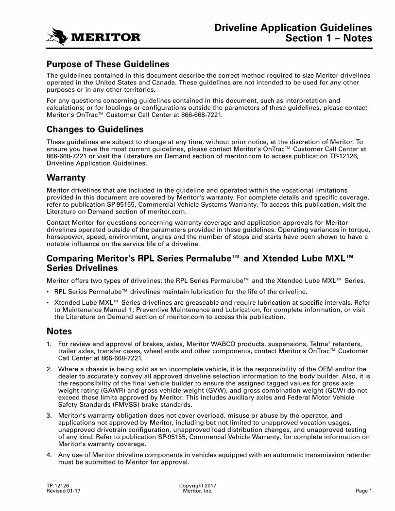
Section 1NotesPurpose of These Guidelines
The guidelines contained in this document describe the correct method required to size Meritor drivelines operated in the United States and Canada. These guidelines are not intended to be used for any other purposes or in any other territories.
For any questions concerning guidelines contained in this document, such as interpretation and calculations; or for loadings or configurations outside the parameters of these guidelines, please contact Meritor's OnTrac™ Customer Call Center at 866-668-7221.
Changes to Guidelines
These guidelines are subject to change at any time, without prior notice, at the discretion of Meritor. To ensure you have the most current guidelines, please contact Meritor's OnTrac™ Customer Call Center at 866-668-7221 or visit the Literature on Demand section of meritor.com to access publication TP-12126, Driveline Application Guidelines.
Warranty
Meritor drivelines that are included in the guideline and operated within the vocational limitations provided in this document are covered by Meritor's warranty. For complete details and specific coverage, refer to publication SP-95155, Commercial Vehicle Systems Warranty. To access this publication, visit the Literature on Demand section of meritor.com.
Contact Meritor for questions concerning warranty coverage and application approvals for Meritor drivelines operated outside of the parameters provided in these guidelines. Operating variances in torque, horsepower, speed, environment, angles and the number of stops and starts have been shown to have a notable influence on the service life of a driveline.
Comparing Meritor's RPL Series Permalube™ and Xtended Lube MXL™ Series Drivelines
Meritor offers two types of drivelines: the RPL Series Permalube™ and the Xtended Lube MXL™ Series.
• RPL Series Permalube™ drivelines maintain lubrication for the life of the driveline.
• Xtended Lube MXL™ Series drivelines are greaseable and require lubrication at specific intervals. Refer to Maintenance Manual 1, Preventive Maintenance and Lubrication, for complete information, or visit the Literature on Demand section of meritor.com to access this publication.
Notes
1. For review and approval of brakes, axles, Meritor WABCO products, suspensions, Telma® retarders, trailer axles, transfer cases, wheel ends and other components, contact Meritor's OnTrac™ Customer Call Center at 866-668-7221.
2. Where a chassis is being sold as an incomplete vehicle, it is the responsibility of the OEM and/or the dealer to accurately convey all approved driveline selection information to the body builder. Also, it is the responsibility of the final vehicle builder to ensure the assigned tagged values for gross axle weight rating (GAWR) and gross vehicle weight (GVW), and gross combination weight (GCW) do not exceed those limits approved by Meritor. This includes auxiliary axles and Federal Motor Vehicle Safety Standards (FMVSS) brake standards.
3. Meritor's warranty obligation does not cover overload, misuse or abuse by the operator, and applications not approved by Meritor, including but not limited to unapproved vocation usages, unapproved drivetrain configuration, unapproved load distribution changes, and unapproved testing of any kind. Refer to publication SP-95155, Commercial Vehicle Warranty, for complete information on Meritor's warranty coverage.
4. Any use of Meritor driveline components in vehicles equipped with an automatic transmission retarder must be submitted to Meritor for approval.
Driveline Application GuidelinesSection 1 – Notes
Copyright 2017 TP-12126Page 2 Meritor, Inc. Revised 01-17
5. Any use of Meritor driveline components in vehicles equipped with hybrid propulsion systems must be submitted to Meritor for approval.
6. For calculated application values outside the standard and approved limits specified in these guidelines, contact your Meritor DriveForce™ representative or Meritor's OnTrac™ Customer Call Center at 866-668-7221. The correct selection of a driveline product depends on correctly identifying the vocation.
7. For Linehaul vocations, the Linehaul sizing charts must be used. The Non-Linehaul sizing charts are not appropriate for the selection of driveline sizes in the Linehaul vocation.
8. For Non-Linehaul vocations, the Non-Linehaul sizing charts must be used.
9. The approval limits in this application guideline apply to driveline systems that follow Meritor's recommendations. For maintenance and service information, please refer to Maintenance Manual MM-96147, Drivelines and Maintenance Manual 1, Preventive Maintenance and Lubrication. Visit Literature on Demand at meritor.com to access these publications.
10. When calculation methods lead to values exceeding the acceptable limits set by this guideline, Meritor advises submitting an application request or contacting Meritor's OnTrac™ Customer Call Center at 866-OnTrac1 (668-7221) for driveline application approval.
11. The swing diameter values in Table 2 shows the diameter measured across the outer most corners of the universal yoke. The swing diameter, together with the tube size aide in determining the necessary clearance for the rotating driveline.
12. These guidelines supersede previous versions.
Driveline Application GuidelinesSection 2 – Requirements
TP-12126 Copyright 2017Revised 01-17 Meritor, Inc. Page 3
Section 4RequirementsThe correct selection and sizing of drivelines is dependent on how the vehicle will be used in service as well as the vehicle characteristics.
1. Maximum driveline torque The use of lower numerical axle ratios increases the possibility of torque spikes in the drivetrain exceeding the maximum rated torque values for the driveline. Driveline maximum-rated torque limits stated in Table 2, Driveline Properties, cannot be exceeded in either steady-state or transient conditions.
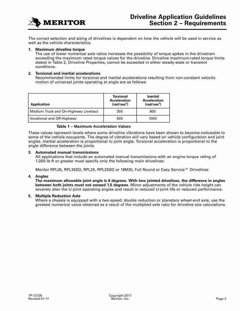
2. Torsional and inertial accelerationsRecommended limits for torsional and inertial accelerations resulting from non-constant velocity motion of universal joints operating at angle are as follows:
Table 1 – Maximum Acceleration Values
These values represent levels where some driveline vibrations have been shown to become noticeable to some of the vehicle occupants. The degree of vibration will vary based on vehicle configuration and joint angles. Inertial acceleration is proportional to joint angle. Torsional acceleration is proportional to the angle difference between the joints.
3. Automated manual transmissionsAll applications that include an automated manual transmissions with an engine torque rating of 1,000 lb-ft or greater must specify only the following main drivelines:
Meritor RPL35, RPL35SD, RPL25, RPL25SD or 18MXL Full Round or Easy Service™ Drivelines
4. AnglesThe maximum allowable joint angle is 6 degrees. With two jointed drivelines, the difference in angles between both joints must not exceed 1.5 degrees. Minor adjustments of the vehicle ride height can severely alter the U-joint operating angles and result in reduced U-joint life or reduced performance.
5. Multiple Reduction AxleWhere a chassis is equipped with a two-speed, double reduction or planetary wheel-end axle, use the greatest numerical value obtained as a result of the multiplied axle ratio for driveline size calculations.
Application
Torsional Acceleration
(rad/sec2)
Inertial Acceleration
(rad/sec2)
Medium Truck and On-Highway Linehaul 300 800
Vocational and Off-Highway 500 1000
Driveline Application GuidelinesSection 3 – Driveline Sizing Process
Copyright 2017 TP-12126Page 4 Meritor, Inc. Revised 01-17
Section 4Driveline Sizing ProcessDefinitions
Linehaul
Linehaul is defined as the long-distance hauling of food, goods and finished materials. Not included are raw ferrous materials, minerals (except oil), logs or log chips. For a vehicle to be considered Linehaul, it must not be used in any type of dual vocation, where part of its duty cycle is outside of the Linehaul definition. Linehaul criteria includes:
• Annual mileage greater than 60,000 miles.
• Start/Stop cycle greater than 30 miles.
• 100% of operation is on paved roads.
Non-Linehaul
• A vehicle that does not meet all the conditions outlined in the Linehaul definition. Any vehicle spending any part of its service life performing outside of the Linehaul definition must be considered Non-Linehaul. This includes vehicles used as Linehaul on a part-time basis (e.g. day shift) and serving an alternate vocation (e.g. City Delivery) for part of the day (e.g. night shift).
• Use of fast axle ratios numerically lower than 2.47 in Non-Linehaul vocations require approval by Meritor.
Inter-axle Shaft Driveline
• A driveline that connects one axle directly to another.
Main Shaft Driveline
• A driveline that connects the transmission to the drive axle or from the transmission to the transfer case and/or from the transfer case to the drive axle.
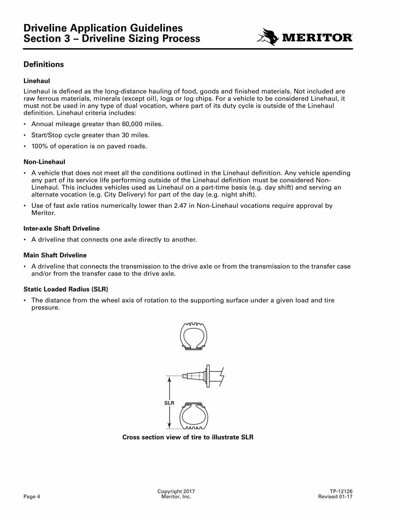
Static Loaded Radius (SLR)
• The distance from the wheel axis of rotation to the supporting surface under a given load and tire pressure.
Cross section view of tire to illustrate SLR
4010252a
SLR
Driveline Application GuidelinesSection 3 – Driveline Sizing Process
TP-12126 Copyright 2017Revised 01-17 Meritor, Inc. Page 5
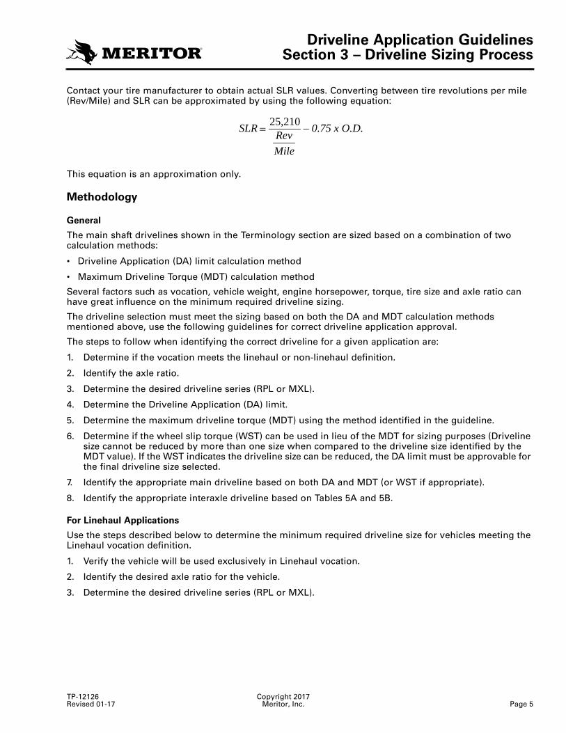
Contact your tire manufacturer to obtain actual SLR values. Converting between tire revolutions per mile (Rev/Mile) and SLR can be approximated by using the following equation:
This equation is an approximation only.
Methodology
General
The main shaft drivelines shown in the Terminology section are sized based on a combination of two calculation methods:
• Driveline Application (DA) limit calculation method
• Maximum Driveline Torque (MDT) calculation method
Several factors such as vocation, vehicle weight, engine horsepower, torque, tire size and axle ratio can have great influence on the minimum required driveline sizing.
The driveline selection must meet the sizing based on both the DA and MDT calculation methods mentioned above, use the following guidelines for correct driveline application approval.
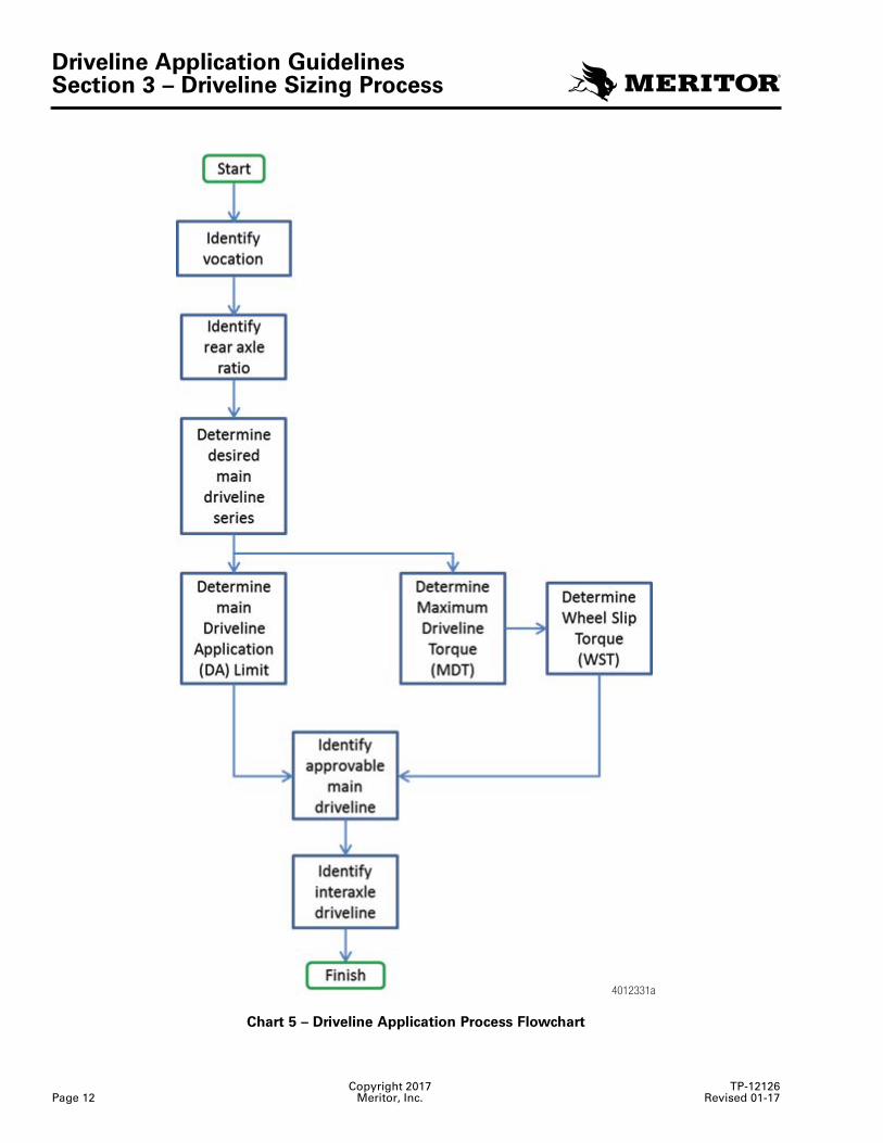
The steps to follow when identifying the correct driveline for a given application are:
1. Determine if the vocation meets the linehaul or non-linehaul definition.
2. Identify the axle ratio.
3. Determine the desired driveline series (RPL or MXL).
4. Determine the Driveline Application (DA) limit.
5. Determine the maximum driveline torque (MDT) using the method identified in the guideline.
6. Determine if the wheel slip torque (WST) can be used in lieu of the MDT for sizing purposes (Driveline size cannot be reduced by more than one size when compared to the driveline size identified by the MDT value). If the WST indicates the driveline size can be reduced, the DA limit must be approvable for the final driveline size selected.
7. Identify the appropriate main driveline based on both DA and MDT (or WST if appropriate).
8. Identify the appropriate interaxle driveline based on Tables 5A and 5B.
For Linehaul Applications
Use the steps described below to determine the minimum required driveline size for vehicles meeting the Linehaul vocation definition.
1. Verify the vehicle will be used exclusively in Linehaul vocation.
2. Identify the desired axle ratio for the vehicle.
3. Determine the desired driveline series (RPL or MXL).
=
MileRevSLR – 0.75 x O.D.25,210
Driveline Application GuidelinesSection 3 – Driveline Sizing Process
Copyright 2017 TP-12126Page 6 Meritor, Inc. Revised 01-17
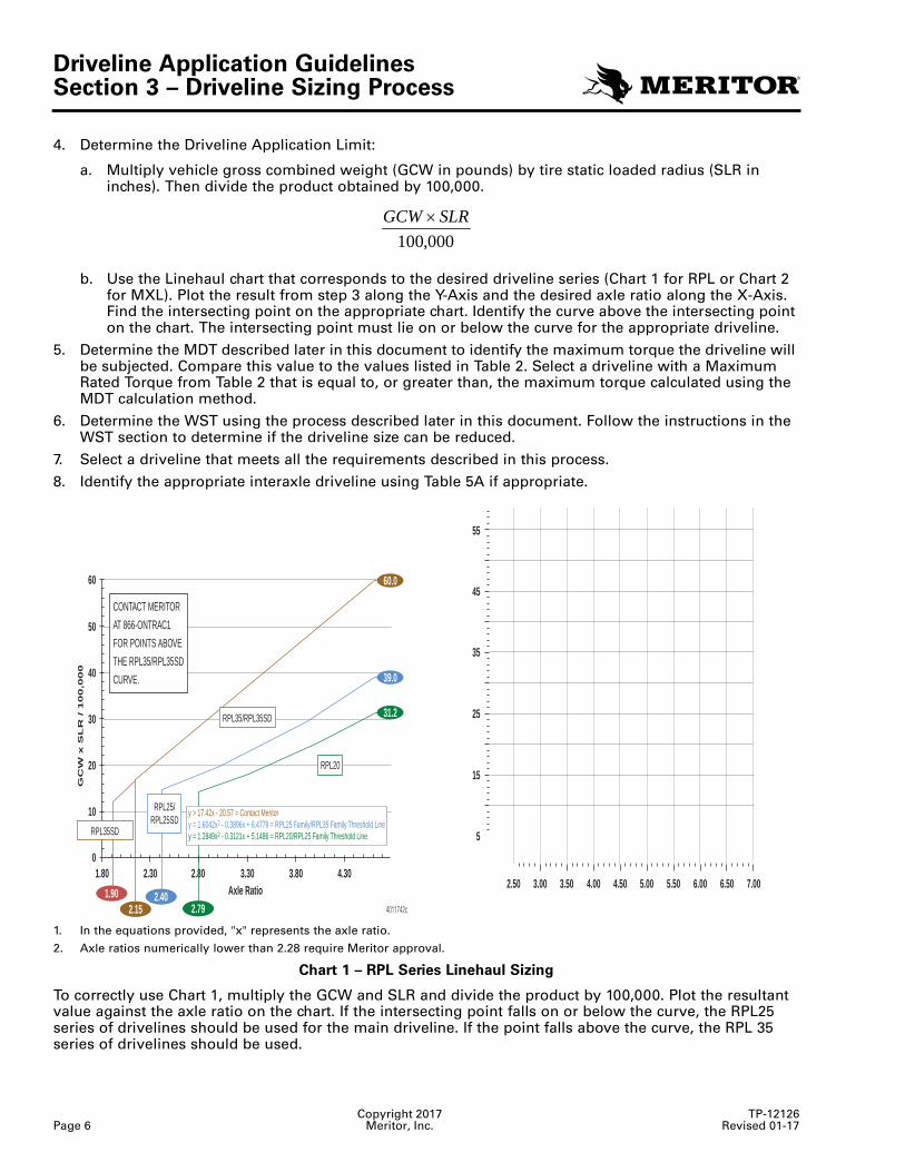
4. Determine the Driveline Application Limit:
a. Multiply vehicle gross combined weight (GCW in pounds) by tire static loaded radius (SLR in inches). Then divide the product obtained by 100,000.
b. Use the Linehaul chart that corresponds to the desired driveline series (Chart 1 for RPL or Chart 2 for MXL). Plot the result from step 3 along the Y-Axis and the desired axle ratio along the X-Axis. Find the intersecting point on the appropriate chart. Identify the curve above the intersecting point on the chart. The intersecting point must lie on or below the curve for the appropriate driveline.
5. Determine the MDT described later in this document to identify the maximum torque the driveline will be subjected. Compare this value to the values listed in Table 2. Select a driveline with a Maximum Rated Torque from Table 2 that is equal to, or greater than, the maximum torque calculated using the MDT calculation method.
6. Determine the WST using the process described later in this document. Follow the instructions in the WST section to determine if the driveline size can be reduced.
7. Select a driveline that meets all the requirements described in this process.
8. Identify the appropriate interaxle driveline using Table 5A if appropriate.
1. In the equations provided, "x" represents the axle ratio.
2. Axle ratios numerically lower than 2.28 require Meritor approval.
Chart 1 – RPL Series Linehaul Sizing
To correctly use Chart 1, multiply the GCW and SLR and divide the product by 100,000. Plot the resultant value against the axle ratio on the chart. If the intersecting point falls on or below the curve, the RPL25 series of drivelines should be used for the main driveline. If the point falls above the curve, the RPL 35 series of drivelines should be used.
000,100SLRGCW ×
4011742c
7.006.506.005.505.004.50Axle Ratio 4.003.503.002.501.80 2.30 2.80 3.30 3.80 4.30
0
5
10
1520
2530
35
GC
W x
SL
R / 1
00
,00
0 40
45
50
55
60
1.902.15
2.402.79
RPL35SD
RPL25/RPL25SD
RPL35/RPL35SD
RPL20
CONTACT MERITOR
AT 866-ONTRAC1
FOR POINTS ABOVE
THE RPL35/RPL35SD
CURVE.
y > 17.42x - 20.57 = Contact Meritory = 1.6042x2 - 0.3896x + 6.4779 = RPL25 Family/RPL35 Family Threshold Liney = 1.2849x2 - 0.3121x + 5.1486 = RPL20/RPL25 Family Threshold Line
60.0
39.0
31.2
Driveline Application GuidelinesSection 3 – Driveline Sizing Process
TP-12126 Copyright 2017Revised 01-17 Meritor, Inc. Page 7
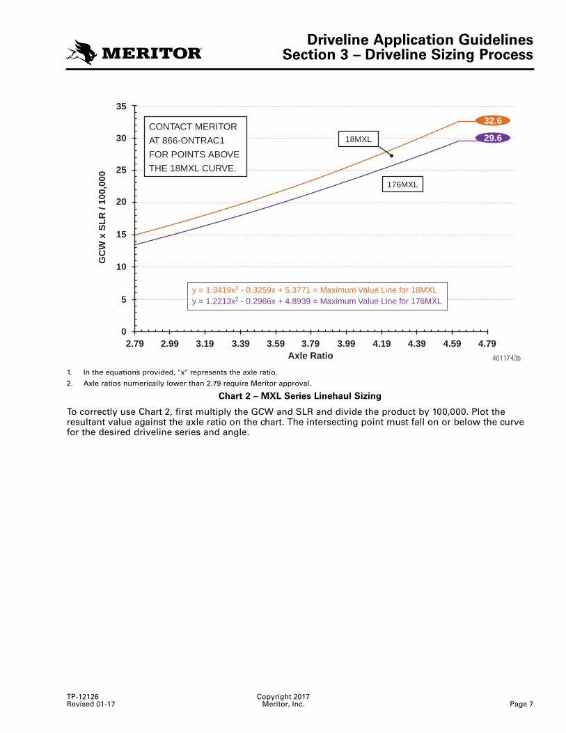
1. In the equations provided, "x" represents the axle ratio.
2. Axle ratios numerically lower than 2.79 require Meritor approval.
Chart 2 – MXL Series Linehaul Sizing
To correctly use Chart 2, first multiply the GCW and SLR and divide the product by 100,000. Plot the resultant value against the axle ratio on the chart. The intersecting point must fall on or below the curve for the desired driveline series and angle.
4011743b
GC
W x
SL
R /
100,
000
35
30
25
20
15
10
5
02.79 2.99 3.19 3.39 3.59 3.79
Axle Ratio3.99 4.19 4.39 4.59 4.79
176MXL
18MXL
CONTACT MERITOR
AT 866-ONTRAC1
FOR POINTS ABOVE
THE 18MXL CURVE.
y = 1.3419x2 - 0.3259x + 5.3771 = Maximum Value Line for 18MXLy = 1.2213x2 - 0.2966x + 4.8939 = Maximum Value Line for 176MXL
32.6
29.6
Driveline Application GuidelinesSection 3 – Driveline Sizing Process
Copyright 2017 TP-12126Page 8 Meritor, Inc. Revised 01-17
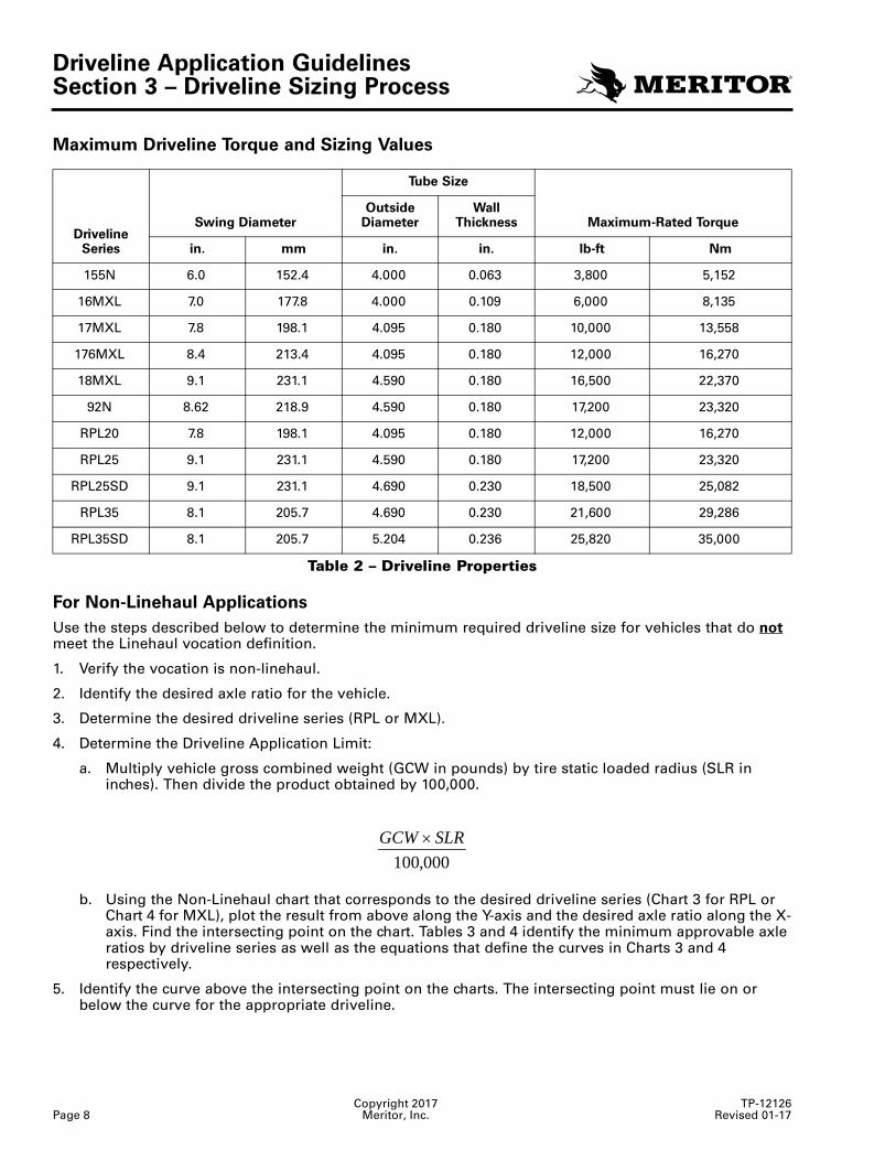
Maximum Driveline Torque and Sizing Values
Table 2 – Driveline Properties
For Non-Linehaul Applications
Use the steps described below to determine the minimum required driveline size for vehicles that do not meet the Linehaul vocation definition.
1. Verify the vocation is non-linehaul.
2. Identify the desired axle ratio for the vehicle.
3. Determine the desired driveline series (RPL or MXL).
4. Determine the Driveline Application Limit:
a. Multiply vehicle gross combined weight (GCW in pounds) by tire static loaded radius (SLR in inches). Then divide the product obtained by 100,000.
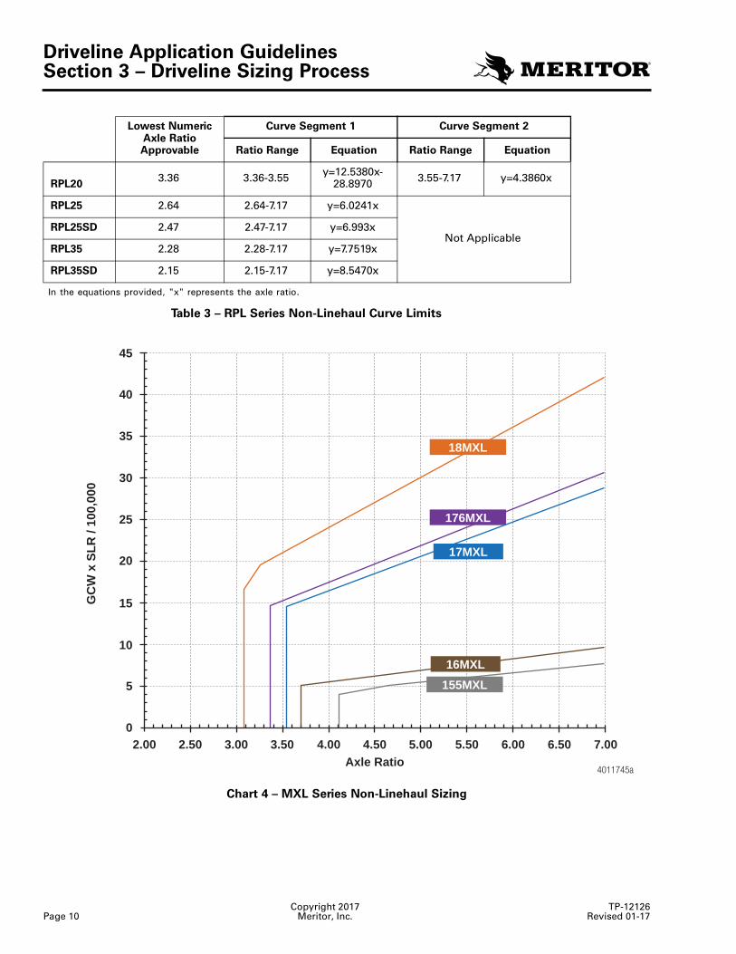
b. Using the Non-Linehaul chart that corresponds to the desired driveline series (Chart 3 for RPL or Chart 4 for MXL), plot the result from above along the Y-axis and the desired axle ratio along the X-axis. Find the intersecting point on the chart. Tables 3 and 4 identify the minimum approvable axle ratios by driveline series as well as the equations that define the curves in Charts 3 and 4 respectively.
5. Identify the curve above the intersecting point on the charts. The intersecting point must lie on or below the curve for the appropriate driveline.
Driveline Series
Tube Size
Swing DiameterOutside
DiameterWall
Thickness Maximum-Rated Torque
in. mm in. in. lb-ft Nm
155N 6.0 152.4 4.000 0.063 3,800 5,152
16MXL 7.0 177.8 4.000 0.109 6,000 8,135
17MXL 7.8 198.1 4.095 0.180 10,000 13,558
176MXL 8.4 213.4 4.095 0.180 12,000 16,270
18MXL 9.1 231.1 4.590 0.180 16,500 22,370
92N 8.62 218.9 4.590 0.180 17,200 23,320
RPL20 7.8 198.1 4.095 0.180 12,000 16,270
RPL25 9.1 231.1 4.590 0.180 17,200 23,320
RPL25SD 9.1 231.1 4.690 0.230 18,500 25,082
RPL35 8.1 205.7 4.690 0.230 21,600 29,286
RPL35SD 8.1 205.7 5.204 0.236 25,820 35,000
000,100SLRGCW ×
Driveline Application GuidelinesSection 3 – Driveline Sizing Process
TP-12126 Copyright 2017Revised 01-17 Meritor, Inc. Page 9
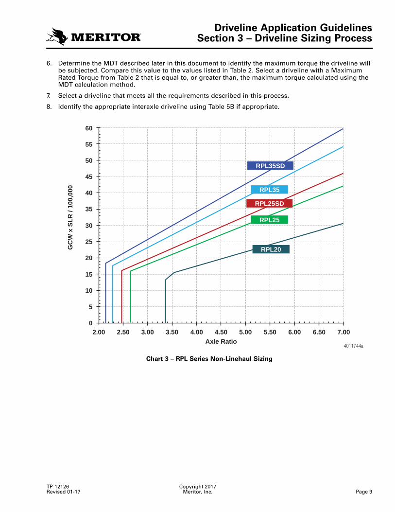
6. Determine the MDT described later in this document to identify the maximum torque the driveline will be subjected. Compare this value to the values listed in Table 2. Select a driveline with a Maximum Rated Torque from Table 2 that is equal to, or greater than, the maximum torque calculated using the MDT calculation method.
7. Select a driveline that meets all the requirements described in this process.
8. Identify the appropriate interaxle driveline using Table 5B if appropriate.
Chart 3 – RPL Series Non-Linehaul Sizing
4011744a
RPL35SD
RPL25SD
RPL35
RPL25
RPL20
7.006.506.005.505.004.50Axle Ratio
4.003.503.002.502.000
5
10
15
20
25
30
35
GC
W x
SL
R /
100,
000
40
45
50
55
60
Driveline Application GuidelinesSection 3 – Driveline Sizing Process
Copyright 2017 TP-12126Page 10 Meritor, Inc. Revised 01-17
Table 3 – RPL Series Non-Linehaul Curve Limits
Chart 4 – MXL Series Non-Linehaul Sizing
Lowest Numeric Axle Ratio Approvable
Curve Segment 1 Curve Segment 2
Ratio Range Equation Ratio Range Equation
RPL203.36 3.36-3.55 y=12.5380x-
28.8970 3.55-7.17 y=4.3860x
RPL25 2.64 2.64-7.17 y=6.0241x
Not ApplicableRPL25SD 2.47 2.47-7.17 y=6.993x
RPL35 2.28 2.28-7.17 y=7.7519x
RPL35SD 2.15 2.15-7.17 y=8.5470x
In the equations provided, "x" represents the axle ratio.
4011745a
155MXL
17MXL
7.006.506.005.505.004.50Axle Ratio
4.003.503.002.502.000
5
10
15
20
25
30
35
GC
W x
SL
R /
100,
000
40
45
18MXL
176MXL
16MXL
Driveline Application GuidelinesSection 3 – Driveline Sizing Process
TP-12126 Copyright 2017Revised 01-17 Meritor, Inc. Page 11
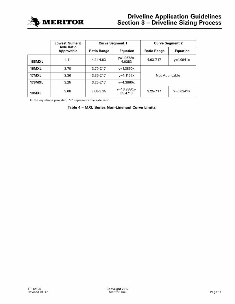
Table 4 – MXL Series Non-Linehaul Curve Limits
Lowest Numeric Axle Ratio Approvable
Curve Segment 1 Curve Segment 2
Ratio Range Equation Ratio Range Equation
155MXL4.11 4.11-4.63 y=1.9672x-
4.0383 4.63-7.17 y=1.0941x
16MXL 3.70 3.70-7.17 y=1.3850x
Not Applicable17MXL 3.36 3.36-7.17 y=4.1152x
176MXL 3.25 3.25-7.17 y=4.3860x
18MXL3.08 3.08-3.25 y=16.9380x-
35.4710 3.25-7.17 Y=6.0241X
In the equations provided, "x" represents the axle ratio.
Driveline Application GuidelinesSection 3 – Driveline Sizing Process
Copyright 2017 TP-12126Page 12 Meritor, Inc. Revised 01-17
Chart 5 – Driveline Application Process Flowchart
4012331a
Driveline Application GuidelinesSection 3 – Driveline Sizing Process
TP-12126 Copyright 2017Revised 01-17 Meritor, Inc. Page 13
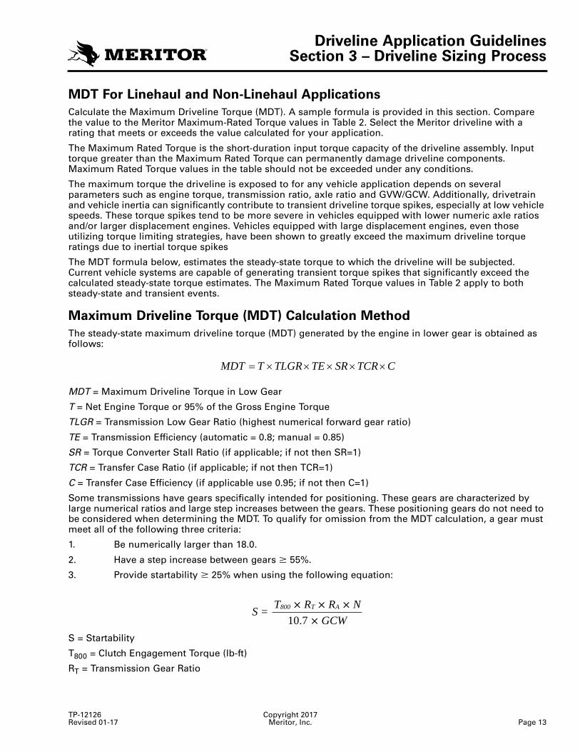
MDT For Linehaul and Non-Linehaul Applications
Calculate the Maximum Driveline Torque (MDT). A sample formula is provided in this section. Compare the value to the Meritor Maximum-Rated Torque values in Table 2. Select the Meritor driveline with a rating that meets or exceeds the value calculated for your application.
The Maximum Rated Torque is the short-duration input torque capacity of the driveline assembly. Input torque greater than the Maximum Rated Torque can permanently damage driveline components. Maximum Rated Torque values in the table should not be exceeded under any conditions.
The maximum torque the driveline is exposed to for any vehicle application depends on several parameters such as engine torque, transmission ratio, axle ratio and GVW/GCW. Additionally, drivetrain and vehicle inertia can significantly contribute to transient driveline torque spikes, especially at low vehicle speeds. These torque spikes tend to be more severe in vehicles equipped with lower numeric axle ratios and/or larger displacement engines. Vehicles equipped with large displacement engines, even those utilizing torque limiting strategies, have been shown to greatly exceed the maximum driveline torque ratings due to inertial torque spikes
The MDT formula below, estimates the steady-state torque to which the driveline will be subjected. Current vehicle systems are capable of generating transient torque spikes that significantly exceed the calculated steady-state torque estimates. The Maximum Rated Torque values in Table 2 apply to both steady-state and transient events.
Maximum Driveline Torque (MDT) Calculation Method
The steady-state maximum driveline torque (MDT) generated by the engine in lower gear is obtained as follows:
MDT = Maximum Driveline Torque in Low Gear
T = Net Engine Torque or 95% of the Gross Engine Torque
TLGR = Transmission Low Gear Ratio (highest numerical forward gear ratio)
TE = Transmission Efficiency (automatic = 0.8; manual = 0.85)
SR = Torque Converter Stall Ratio (if applicable; if not then SR=1)
TCR = Transfer Case Ratio (if applicable; if not then TCR=1)
C = Transfer Case Efficiency (if applicable use 0.95; if not then C=1)
Some transmissions have gears specifically intended for positioning. These gears are characterized by large numerical ratios and large step increases between the gears. These positioning gears do not need to be considered when determining the MDT. To qualify for omission from the MDT calculation, a gear must meet all of the following three criteria:
1. Be numerically larger than 18.0.
2. Have a step increase between gears � 55%.
3. Provide startability � 25% when using the following equation:
S = Startability
T800 = Clutch Engagement Torque (lb-ft)
RT = Transmission Gear Ratio
CTCRSRTETLGRTMDT ×××××=
S =10.7 � GCW
T800 � RT � RA � N
Driveline Application GuidelinesSection 3 – Driveline Sizing Process
Copyright 2017 TP-12126Page 14 Meritor, Inc. Revised 01-17
RA = Axle Gear Ratio
N = Number of Revolutions per Mile of the Tire
GCW = Gross Combined Weight
If a transmission gear ratio meets all three of these requirements, the next gear ratio in the transmission may be used to determine the MDT.
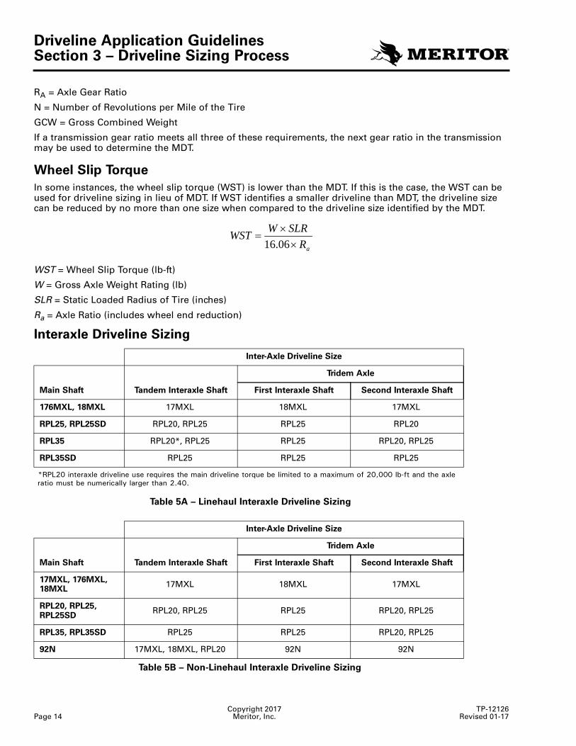
Wheel Slip Torque
In some instances, the wheel slip torque (WST) is lower than the MDT. If this is the case, the WST can be used for driveline sizing in lieu of MDT. If WST identifies a smaller driveline than MDT, the driveline size can be reduced by no more than one size when compared to the driveline size identified by the MDT.
WST = Wheel Slip Torque (lb-ft)
W = Gross Axle Weight Rating (lb)
SLR = Static Loaded Radius of Tire (inches)
Ra = Axle Ratio (includes wheel end reduction)
Interaxle Driveline Sizing
Table 5A – Linehaul Interaxle Driveline Sizing
Table 5B – Non-Linehaul Interaxle Driveline Sizing
Inter-Axle Driveline Size
Main Shaft Tandem Interaxle Shaft
Tridem Axle
First Interaxle Shaft Second Interaxle Shaft
176MXL, 18MXL 17MXL 18MXL 17MXL
RPL25, RPL25SD RPL20, RPL25 RPL25 RPL20
RPL35 RPL20*, RPL25 RPL25 RPL20, RPL25
RPL35SD RPL25 RPL25 RPL25
*RPL20 interaxle driveline use requires the main driveline torque be limited to a maximum of 20,000 lb-ft and the axle ratio must be numerically larger than 2.40.
Inter-Axle Driveline Size
Main Shaft Tandem Interaxle Shaft
Tridem Axle
First Interaxle Shaft Second Interaxle Shaft
17MXL, 176MXL, 18MXL
17MXL 18MXL 17MXL
RPL20, RPL25, RPL25SD
RPL20, RPL25 RPL25 RPL20, RPL25
RPL35, RPL35SD RPL25 RPL25 RPL20, RPL25
92N 17MXL, 18MXL, RPL20 92N 92N
aRSLRWWST×
×=
06.16
Driveline Application GuidelinesSection 4 – Terminology
TP-12126 Copyright 2017Revised 01-17 Meritor, Inc. Page 15
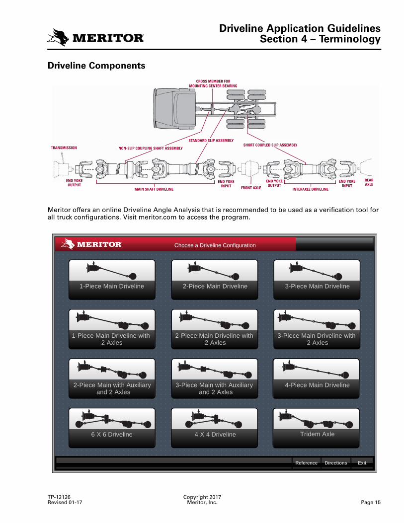
GlossaryDriveline ComponentsService Brake Ratings
Meritor offers an online Driveline Angle Analysis that is recommended to be used as a verification tool for all truck configurations. Visit meritor.com to access the program.
4010259a
END YOKEOUTPUT
END YOKEOUTPUT
END YOKEINPUT
END YOKEINPUT
REARAXLE
FRONT AXLE
TRANSMISSIONSHORT COUPLED SLIP ASSEMBLY
STANDARD SLIP ASSEMBLY
NON-SLIP COUPLING SHAFT ASSEMBL
MAIN SHAFT DRIVELINE
Y
CROSS MEMBER FORMOUNTING CENTER BEARING
INTERAXLE DRIVELINE
4010251a
1-Piece Main Driveline 2-Piece Main Driveline 3-Piece Main Driveline
1-Piece Main Driveline with2 Axles
2-Piece Main Driveline with2 Axles
3-Piece Main Driveline with2 Axles
4-Piece Main Driveline
Tridem Axle
2-Piece Main with Auxiliaryand 2 Axles
3-Piece Main with Auxiliaryand 2 Axles
6 X 6 Driveline 4 X 4 Driveline
Reference Directions Exit
Choose a Driveline Configuration
Driveline Application GuidelinesSection 4 – Terminology
Copyright 2017 TP-12126Page 16 Meritor, Inc. Revised 01-17
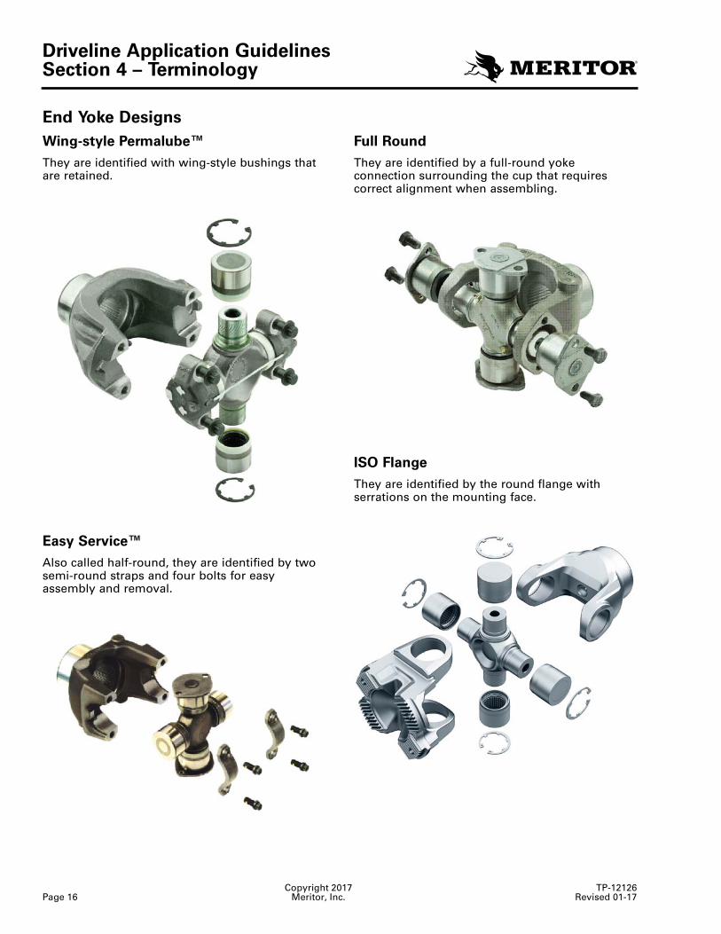
End Yoke Designs
Wing-style Permalube™
They are identified with wing-style bushings that are retained.
Easy Service™
Also called half-round, they are identified by two semi-round straps and four bolts for easy assembly and removal.
Full Round
They are identified by a full-round yoke connection surrounding the cup that requires correct alignment when assembling.
ISO Flange
They are identified by the round flange with serrations on the mounting face.
4010267a
4010268a
Driveline Application GuidelinesSection 4 – Terminology
TP-12126 Copyright 2017Revised 01-17 Meritor, Inc. Page 17
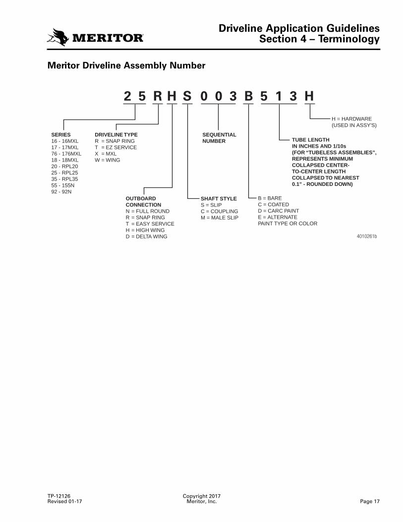
Meritor Driveline Assembly Number
4010261b
2 5 R H S 0 0 3 B 5 1 3 H
SERIES16 - 16MXL17 - 17MXL76 - 176MXL18 - 18MXL20 - RPL2025 - RPL2535 - RPL3555 - 155N92 - 92N
DRIVELINE TYPER = SNAP RINGT = EZ SERVICEX = MXLW = WING
OUTBOARDCONNECTIONN = FULL ROUNDR = SNAP RINGT = EASY SERVICEH = HIGH WINGD = DELTA WING
SHAFT STYLES = SLIPC = COUPLINGM = MALE SLIP
B = BAREC = COATEDD = CARC PAINTE = ALTERNATEPAINT TYPE OR COLOR
H = HARDWARE(USED IN ASSY'S)
SEQUENTIALNUMBER TUBE LENGTH
IN INCHES AND 1/10s(FOR “TUBELESS ASSEMBLIES”,REPRESENTS MINIMUMCOLLAPSED CENTER-TO-CENTER LENGTHCOLLAPSED TO NEAREST0.1" - ROUNDED DOWN)

Meritor Heavy Vehicle Systems, LLC2135 West Maple Road Printed in USATroy, MI 48084 USA866-OnTrac1 (668-7221) Copyright 2017 Revised 01-17meritor.com Meritor, Inc. TP-12126 (16579)