Embed Size (px)
DESCRIPTION
Official Manual from Autodesk Seek
Citation preview
REVIT CATEGORY‐SPECIFIC GUIDELINES: FURNITURE SYSTEMS CATEGORY – FURNITURE SYSTEMS
FAMILIES This document includes Autodesk specifications for the creation of Revit furniture systems families within the Revit Furniture systems category. By following the criteria suggested by both this guide and the Revit Model Content Style Guide, manufacturers and other content creators can create Furniture Systems families that adhere to Autodesk and Autodesk® Seek standards for Revit furniture systems families.
While this document contains specific system furniture family creation guidelines, it is not intended to provide specifications for every kind of system furniture family.
RMCSG 2.1 — page 1
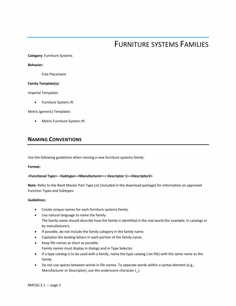
FURNITURE SYSTEMS FAMILIES Category: Furniture Systems
Behavior:
Free Placement
Family Template(s):
Imperial Templates
• Furniture System.rft
Metric (generic) Templates
• Metric Furniture System.rft
NAMING CONVENTIONS
Use the following guidelines when naming a new furniture systems family:
Format:
<Functional Type>‐ <Subtype>‐<Manufacturer>‐< Descriptor 1>‐<Descriptor2>
Note: Refer to the Revit Master Part Type List (included in the download package) for information on approved Function Types and Subtypes.
Guidelines:
• Create unique names for each furniture systems family.
• Use natural language to name the family. The family name should describe how the family is identified in the real world (for example, in catalogs or by manufacturer).
• If possible, do not include the family category in the family name.
• Capitalize the leading letters in each portion of the family name.
• Keep file names as short as possible. Family names must display in dialogs and in Type Selector.
• If a type catalog is to be used with a family, name the type catalog (.txt file) with the same name as the family.
• Do not use spaces between words in file names. To separate words within a syntax element (e.g., Manufacturer or Descriptor), use the underscore character (_).
RMCSG 2.1 — page 2
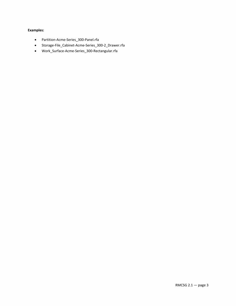
Examples:
• Partition‐Acme‐Series_300‐Panel.rfa
• Storage‐File_Cabinet‐Acme‐Series_300‐2_Drawer.rfa
• Work_Surface‐Acme‐Series_300‐Rectangular.rfa
RMCSG 2.1 — page 3
SUBCATEGORIES
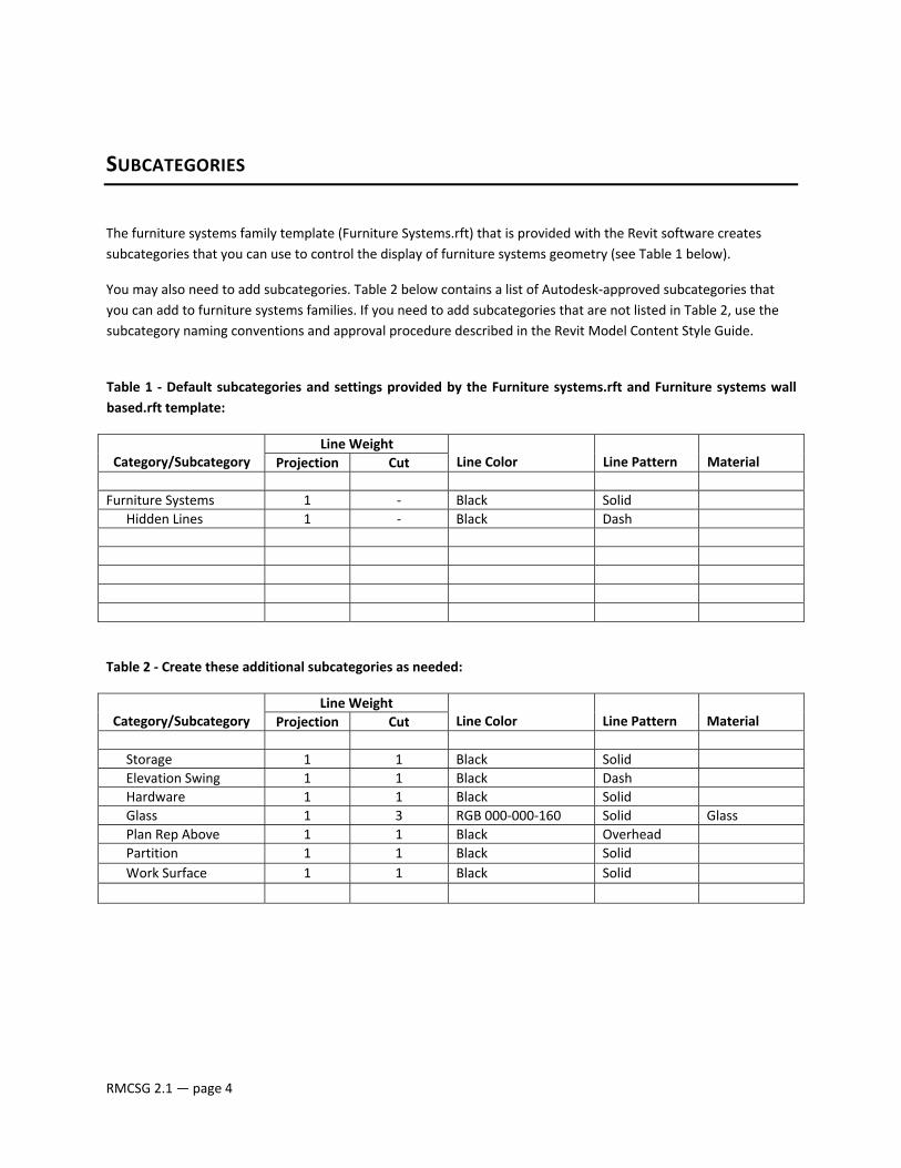
The furniture systems family template (Furniture Systems.rft) that is provided with the Revit software creates subcategories that you can use to control the display of furniture systems geometry (see Table 1 below).
You may also need to add subcategories. Table 2 below contains a list of Autodesk‐approved subcategories that you can add to furniture systems families. If you need to add subcategories that are not listed in Table 2, use the subcategory naming conventions and approval procedure described in the Revit Model Content Style Guide.
Table 1 ‐ Default subcategories and settings provided by the Furniture systems.rft and Furniture systems wall based.rft template:
Category/Subcategory
Line WeightLine Color Line Pattern
Material Projection Cut
Furniture Systems 1 ‐ Black Solid Hidden Lines 1 ‐ Black Dash
Table 2 ‐ Create these additional subcategories as needed:
Category/Subcategory
Line WeightLine Color Line Pattern
Material Projection Cut
Storage 1 1 Black Solid Elevation Swing 1 1 Black Dash Hardware 1 1 Black Solid Glass 1 3 RGB 000‐000‐160 Solid Glass Plan Rep Above 1 1 Black Overhead Partition 1 1 Black Solid Work Surface 1 1 Black Solid
RMCSG 2.1 — page 4

REFERENCE PLANES
Use reference planes in furniture system families to control dimensioning and snapping. A number of predefined and named reference planes are provided by the template that you use when you create a furniture system family.
Table 1 ‐ Reference Planes provided by the Furniture systems.rft template:
Name Is Reference (strength) Defines Origin? Center (Left/Right) Center (Left/Right) (Strong) YesBack Back (Strong) YesLeft Left (Strong) NoRight Right (Strong) NoTop Top (Strong) NoFront Front (Strong) No
If you need to add reference planes to a furniture systems family:
• Any reference planes that you do not need to dimension or snap to, should be set to an Is Reference value of “Not a Reference.”
• Keep reference plane naming consistent with those provided by the template.
RMCSG 2.1 — page 5
PARAMETER USAGE
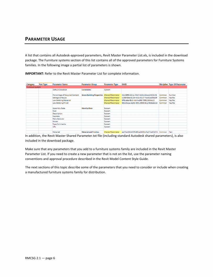
A list that contains all Autodesk‐approved parameters, Revit Master Parameter List.xls, is included in the download package. The Furniture systems section of this list contains all of the approved parameters for Furniture Systems families. In the following image a partial list of parameters is shown.
IMPORTANT: Refer to the Revit Master Parameter List for complete information.
In addition, the Revit Master Shared Parameter.txt file (including standard Autodesk shared parameters), is also included in the download package.
Make sure that any parameters that you add to a furniture systems family are included in the Revit Master Parameter List. If you need to create a new parameter that is not on the list, use the parameter naming conventions and approval procedure described in the Revit Model Content Style Guide.
The next sections of this topic describe some of the parameters that you need to consider or include when creating a manufactured furniture systems family for distribution.
RMCSG 2.1 — page 6
DIMENSION PARAMETERS The main dimensional parameters for furniture systems families are:
• Depth
• Height
• Width
The Depth, Height, and Width parameters determine the basic dimensions of furniture systems families.
CSI – OMNICLASS 1.0, MASTERFORMAT 2004, AND UNIFORMAT II PARAMETERS On Autodesk Seek, furniture systems families can be located by the appropriate CSI Omniclass 1.0, MasterFormat 2004, and UniFormat II codes. When sharing content with Autodesk Seek, indicate the code within the classification that should be assigned to the content.
Refer to the Revit Model Content Style Guide for information on including CSI Classification Codes with Revit families.
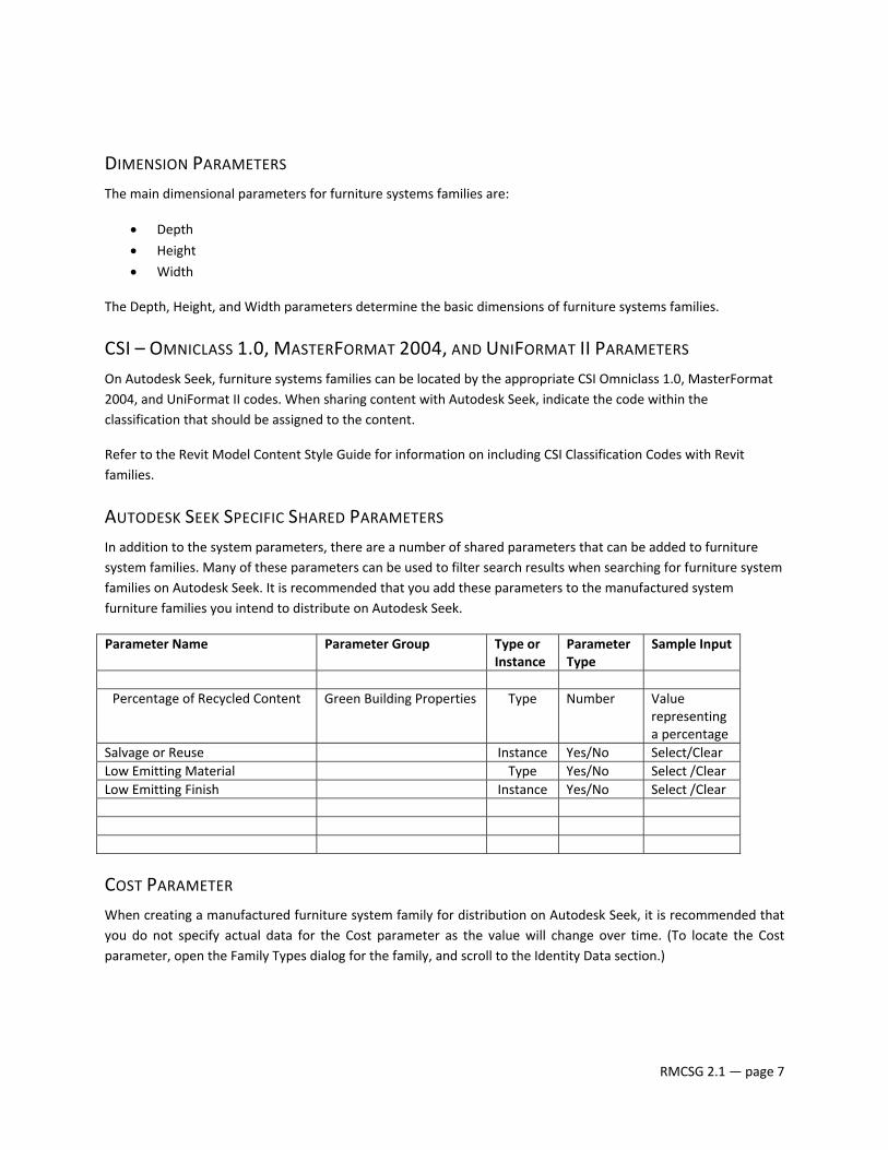
AUTODESK SEEK SPECIFIC SHARED PARAMETERS In addition to the system parameters, there are a number of shared parameters that can be added to furniture system families. Many of these parameters can be used to filter search results when searching for furniture system families on Autodesk Seek. It is recommended that you add these parameters to the manufactured system furniture families you intend to distribute on Autodesk Seek.
Parameter Name Parameter Group Type or Instance
Parameter Type
Sample Input
Percentage of Recycled Content
Green Building Properties Type Number Value representing a percentage
Salvage or Reuse Instance Yes/No Select/ClearLow Emitting Material Type Yes/No Select /ClearLow Emitting Finish Instance Yes/No Select /Clear
COST PARAMETER When creating a manufactured furniture system family for distribution on Autodesk Seek, it is recommended that you do not specify actual data for the Cost parameter as the value will change over time. (To locate the Cost parameter, open the Family Types dialog for the family, and scroll to the Identity Data section.)
RMCSG 2.1 — page 7
TYPES
NAMING CONVENTIONS All furniture systems families must include one predefined type. For families that create real‐world objects that are available in standard sizes, predefined types should be generated. Unless they represent nominal sizes, type names should include units or capacity, and include a unit indicator.
Format:
For manufacturer‐specific furniture systems content:
Use the manufacturer‐specific code for the furniture systems name and size:
<manufacturer code> ‐ <size(optional)>
Examples:
FP34‐T FS‐1522 FT321 – 24” x 48” WS‐R – 24” x 60”
For generic furniture systems content:
Unless there is a market‐specific reason to do otherwise, use this general format for furniture systems type names:
<width> x <height>
For imperial family types:
In most cases, size should be expressed in inches. Use only one of the conventions below within a family and for related families.
For families with most sizes under 10’: XX” x YY”
For families with most sizes over 10’: XX’ – YY” x AA’ – BB”
For metric family types:
For all types in metric families: XXXX x YYYYmm (or local metric unit indicator)
RMCSG 2.1 — page 8
FURNITURE SYSTEMS REPRESENTATIONS IN STANDARD VIEWS
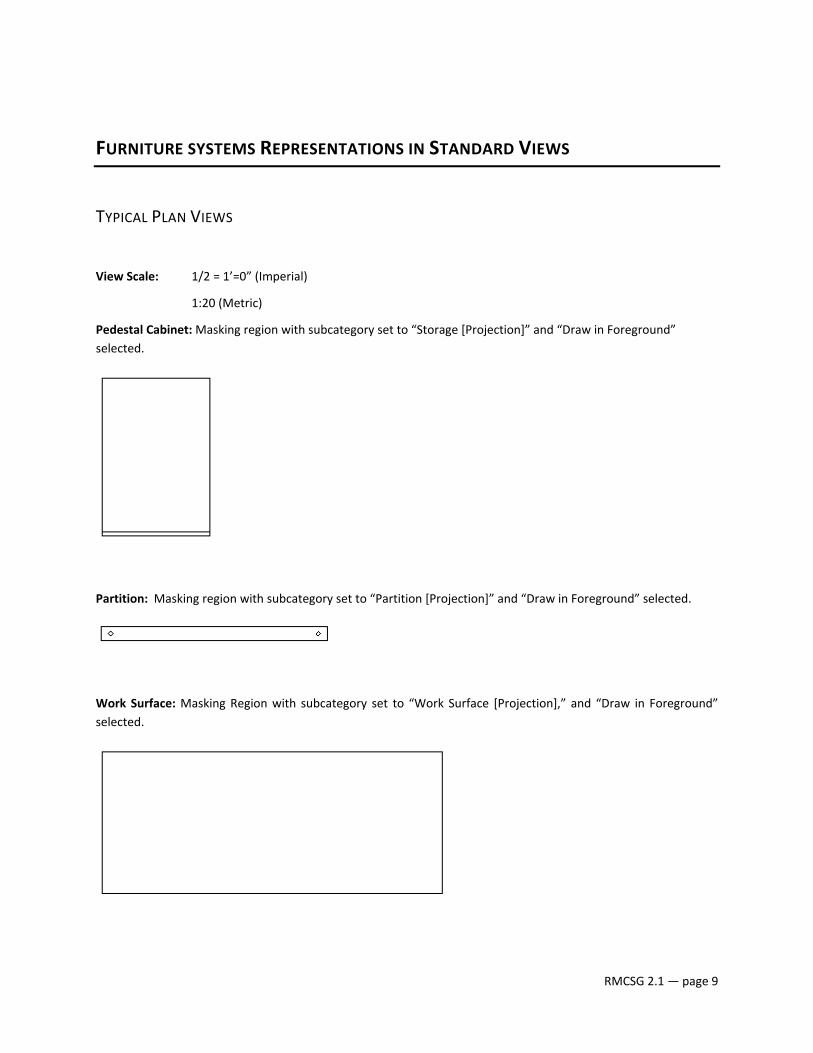
TYPICAL PLAN VIEWS
View Scale: 1/2 = 1’=0” (Imperial)
1:20 (Metric)
Pedestal Cabinet: Masking region with subcategory set to “Storage [Projection]” and “Draw in Foreground” selected.
Partition: Masking region with subcategory set to “Partition [Projection]” and “Draw in Foreground” selected.
Work Surface: Masking Region with subcategory set to “Work Surface [Projection],” and “Draw in Foreground” selected.
RMCSG 2.1 — page 9
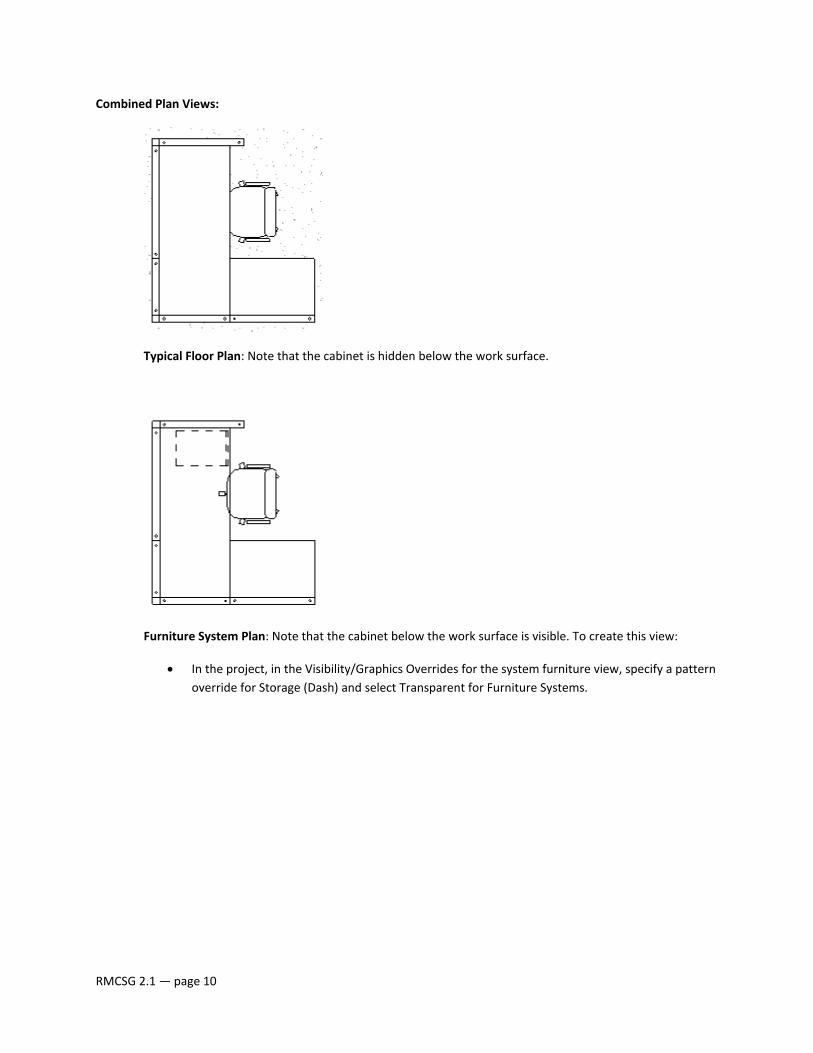
Combined Plan Views:
Typical Floor Plan: Note that the cabinet is hidden below the work surface.
Furniture System Plan: Note that the cabinet below the work surface is visible. To create this view:
• In the project, in the Visibility/Graphics Overrides for the system furniture view, specify a pattern override for Storage (Dash) and select Transparent for Furniture Systems.
RMCSG 2.1 — page 10
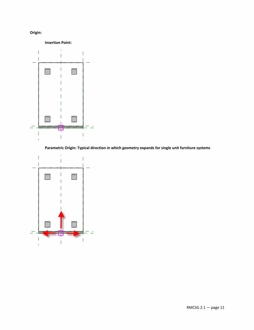
Origin:
Insertion Point:
Parametric Origin: Typical direction in which geometry expands for single unit furniture systems
RMCSG 2.1 — page 11
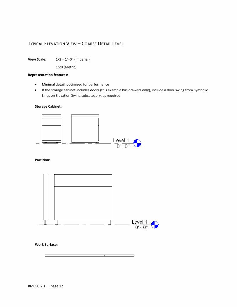
TYPICAL ELEVATION VIEW – COARSE DETAIL LEVEL View Scale: 1/2 = 1’=0” (Imperial)
1:20 (Metric)
Representation features:
• Minimal detail, optimized for performance
• If the storage cabinet includes doors (this example has drawers only), include a door swing from Symbolic Lines on Elevation Swing subcategory, as required.
Storage Cabinet:
Partition:
Work Surface:
RMCSG 2.1 — page 12
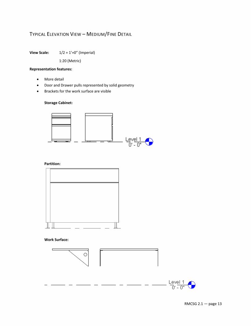
TYPICAL ELEVATION VIEW – MEDIUM/FINE DETAIL
View Scale: 1/2 = 1’=0” (Imperial)
1:20 (Metric)
Representation features:
• More detail
• Door and Drawer pulls represented by solid geometry
• Brackets for the work surface are visible
Storage Cabinet:
Partition:
Work Surface:
RMCSG 2.1 — page 13
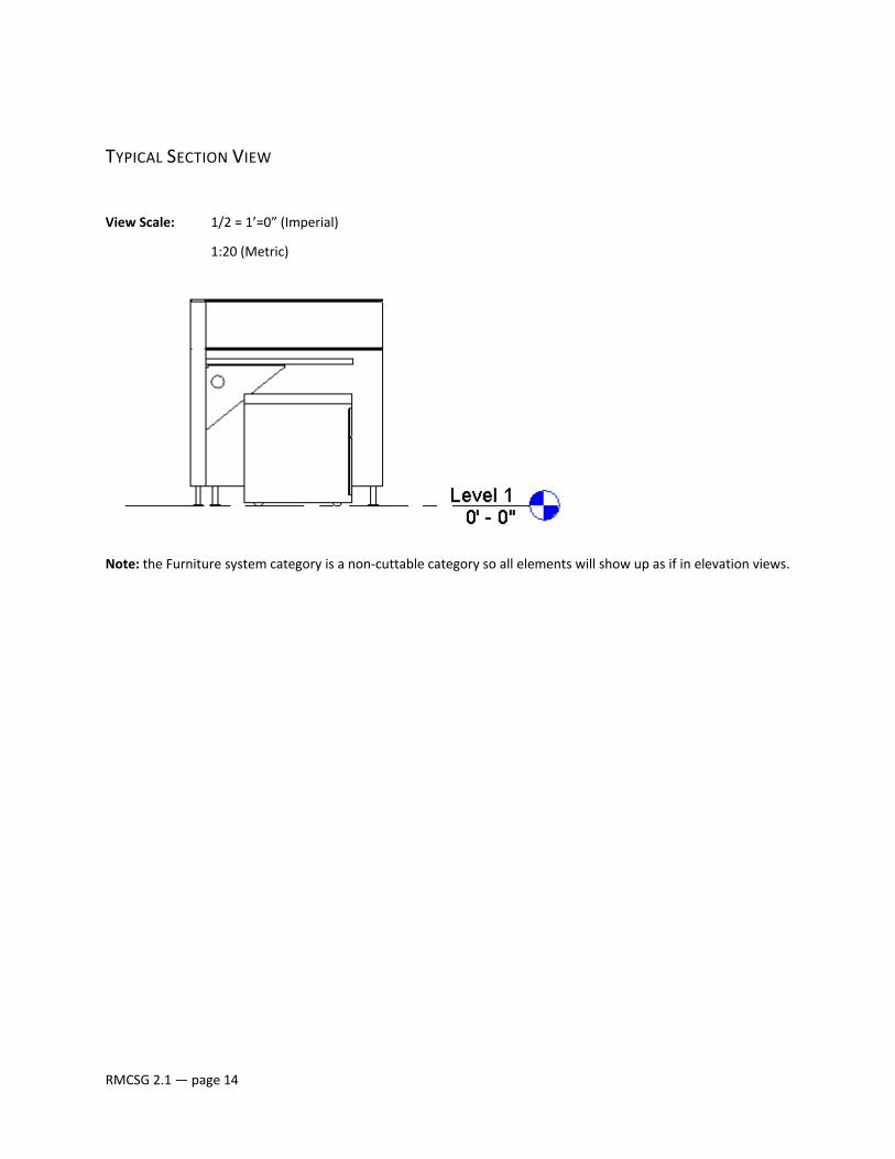
TYPICAL SECTION VIEW
View Scale: 1/2 = 1’=0” (Imperial)
1:20 (Metric)
Note: the Furniture system category is a non‐cuttable category so all elements will show up as if in elevation views.
RMCSG 2.1 — page 14

PREVIEW VIEW
View Scale: 1 1/2” = 1’‐0” (for an imperial family) or 1:5 (for a metric family)
Representation features:
• Furniture systems displays in a southeast isometric view.
• For wall‐based furniture systems, the visibility is switched off for the host geometry (the wall), dimensions, and reference planes.
• Model Graphics Style is set to Shading with Edges.
• The Detail Level is set to Fine.
NOTE: See the Revit Model Content Style Guide for Preview view creation guidelines.
RMCSG 2.1 — page 15
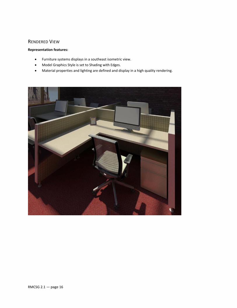
RENDERED VIEW Representation features:
• Furniture systems displays in a southeast isometric view.
• Model Graphics Style is set to Shading with Edges.
• Material properties and lighting are defined and display in a high quality rendering.
RMCSG 2.1 — page 16
BEST PRACTICES
In addition to the guidelines published in the Revit Model Content Style Guide, use these furniture systems‐specific best practices:
TYPE CATALOGS • For furniture systems families that contain more than six types (sizes), create a type catalog.
PERFORMANCE • Do not model hidden faces.
• Only model simplified door and drawer pulls, do not model hinges and locksets
• Set door and drawer pulls to Medium and Fine Level of Detail
• Nesting geometry in furniture system families increases family file size and decreases performance. Use nesting only where appropriate (e.g., brackets) to allow itemization in schedules.
RENDERING • To ensure panels render with enough edge definition use a minimum gap of 1/8” between geometry
edges.
RMCSG 2.1 — page 17
TESTING GUIDELINES
Use these furniture systems‐specific testing guidelines as a supplement to the general testing guidelines in the Revit Model Content Style Guide.
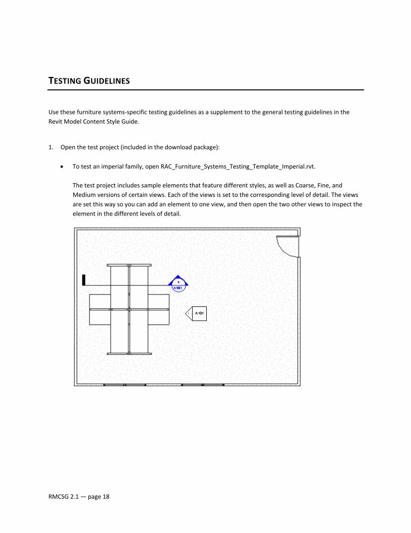
1. Open the test project (included in the download package):
• To test an imperial family, open RAC_Furniture_Systems_Testing_Template_Imperial.rvt. The test project includes sample elements that feature different styles, as well as Coarse, Fine, and Medium versions of certain views. Each of the views is set to the corresponding level of detail. The views are set this way so you can add an element to one view, and then open the two other views to inspect the element in the different levels of detail.
RMCSG 2.1 — page 18
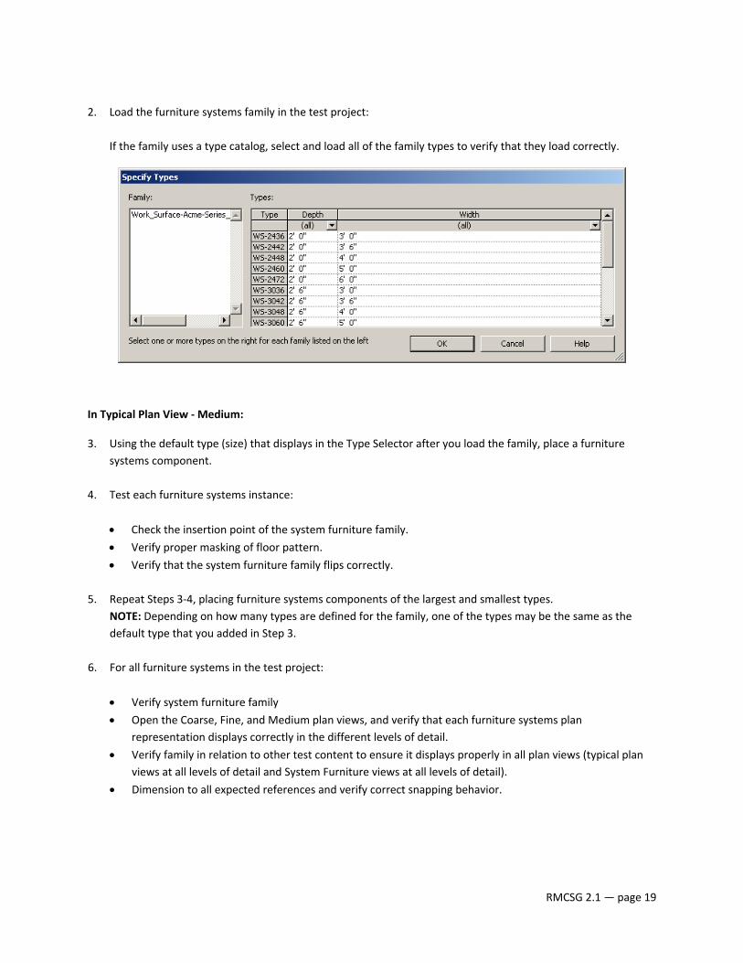
2. Load the furniture systems family in the test project:
If the family uses a type catalog, select and load all of the family types to verify that they load correctly.
In Typical Plan View ‐ Medium:
3. Using the default type (size) that displays in the Type Selector after you load the family, place a furniture systems component.
4. Test each furniture systems instance:
• Check the insertion point of the system furniture family.
• Verify proper masking of floor pattern.
• Verify that the system furniture family flips correctly.
5. Repeat Steps 3‐4, placing furniture systems components of the largest and smallest types. NOTE: Depending on how many types are defined for the family, one of the types may be the same as the default type that you added in Step 3.
6. For all furniture systems in the test project:
• Verify system furniture family
• Open the Coarse, Fine, and Medium plan views, and verify that each furniture systems plan representation displays correctly in the different levels of detail.
• Verify family in relation to other test content to ensure it displays properly in all plan views (typical plan views at all levels of detail and System Furniture views at all levels of detail).
• Dimension to all expected references and verify correct snapping behavior.
RMCSG 2.1 — page 19
In the remaining views (elevations, sections, 3D views, Preview):
7. Inspect the furniture systems in each view in Coarse, Medium, and Fine detail levels.
8. In 3D View, inspect the furniture systems geometry:
• Use the Orbit tool on the SteeringWheels to spin the walls and furniture systems, and verify that the geometry is constrained as expected. Check for unconnected geometry and/or plan representations that may be disconnected from the geometry.
• Apply the following Model Graphics Style to the view, and verify that any materials applied to the furniture systems display correctly:
o Hidden Line
o Shading with Edges
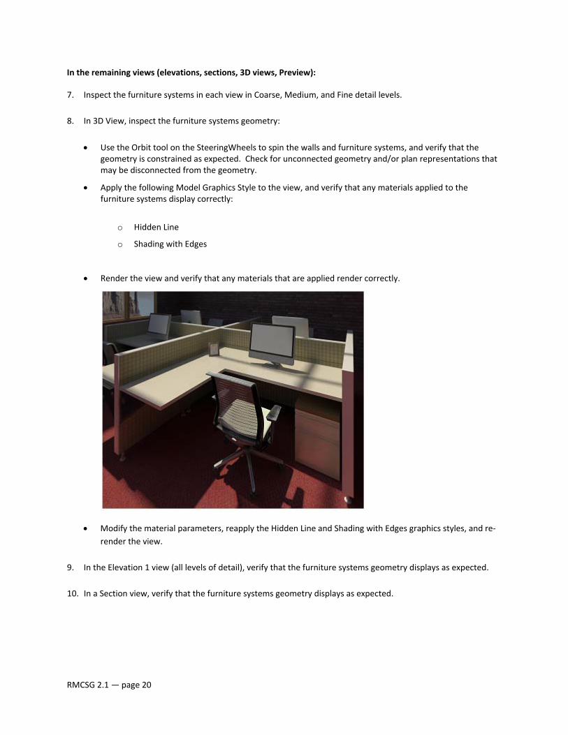
• Render the view and verify that any materials that are applied render correctly.
• Modify the material parameters, reapply the Hidden Line and Shading with Edges graphics styles, and re‐render the view.
9. In the Elevation 1 view (all levels of detail), verify that the furniture systems geometry displays as expected.
10. In a Section view, verify that the furniture systems geometry displays as expected.
RMCSG 2.1 — page 20
RMCSG 2.1 — page 21
11. Open the family in the family editor, and for the Preview view, verify that:
• Dimension and reference plane visibility is turned off.
• View Scale is set to 1 1/2” = 1’‐0” (for an imperial family) or 1:5 (for a metric family).
• Model Graphics Style is set to Shading with Edges.
• Detail Level is set to Fine.
• The Preview view is set to the current view.
In the test project, in any view:
12. Create a furniture systems schedule and verify the furniture systems parameters (including any shared parameters that were applied) schedule correctly.
13. Select a furniture systems component in the test project, and:
• verify the furniture systems type properties.
• check all parameter names to ensure that they adhere to naming conventions and do not contain errors. �