Embed Size (px)
Citation preview
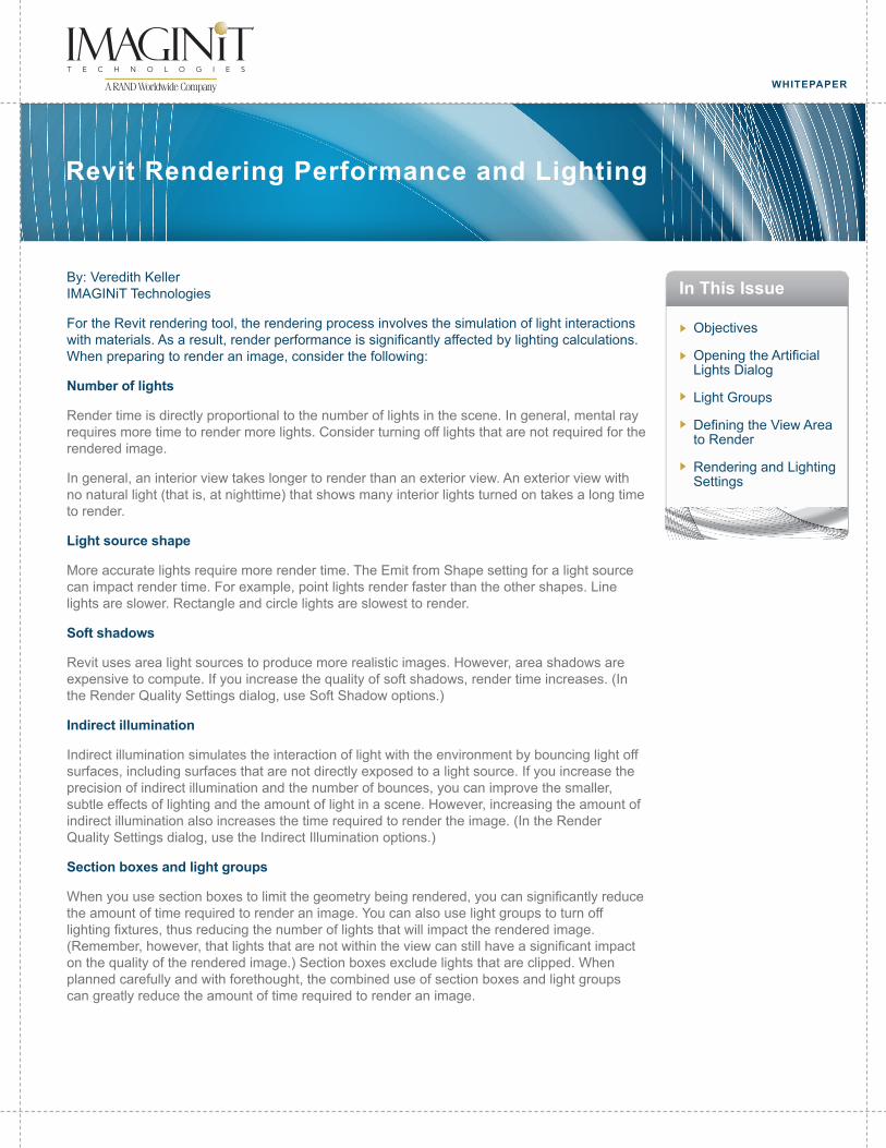
WHITEPAPER
By: Veredith Keller IMAGINiT Technologies
For the Revit rendering tool, the rendering process involves the simulation of light interactions with materials. As a result, render performance is significantly affected by lighting calculations. When preparing to render an image, consider the following:
Number of lights
Render time is directly proportional to the number of lights in the scene. In general, mental ray requires more time to render more lights. Consider turning off lights that are not required for the rendered image.
In general, an interior view takes longer to render than an exterior view. An exterior view with no natural light (that is, at nighttime) that shows many interior lights turned on takes a long time to render.
Light source shape
More accurate lights require more render time. The Emit from Shape setting for a light source can impact render time. For example, point lights render faster than the other shapes. Line lights are slower. Rectangle and circle lights are slowest to render.
Soft shadows
Revit uses area light sources to produce more realistic images. However, area shadows are expensive to compute. If you increase the quality of soft shadows, render time increases. (In the Render Quality Settings dialog, use Soft Shadow options.)
Indirect illumination
Indirect illumination simulates the interaction of light with the environment by bouncing light off surfaces, including surfaces that are not directly exposed to a light source. If you increase the precision of indirect illumination and the number of bounces, you can improve the smaller, subtle effects of lighting and the amount of light in a scene. However, increasing the amount of indirect illumination also increases the time required to render the image. (In the Render Quality Settings dialog, use the Indirect Illumination options.)
Section boxes and light groups
When you use section boxes to limit the geometry being rendered, you can significantly reduce the amount of time required to render an image. You can also use light groups to turn off lighting fixtures, thus reducing the number of lights that will impact the rendered image.(Remember, however, that lights that are not within the view can still have a significant impact on the quality of the rendered image.) Section boxes exclude lights that are clipped. When planned carefully and with forethought, the combined use of section boxes and light groups can greatly reduce the amount of time required to render an image.
Objectives
Opening the Artificial Lights Dialog
Light Groups
Defining the View Area to Render
Rendering and Lighting Settings
In This Issue
Revit Rendering Performance and Lighting
Objectives
Opening the Artificial Lights Dialog
Making Light Groups Using the Artificial Lights Dialog
Adding and Removing Lights in a Light Group Using the Artificial Lights Dialog
Defining a View Area to Render
Rendering and Lighting Settings
Opening the Artificial Lights Dialog
The Artificial Lights dialog lists all lighting fixtures in the building model, including ungrouped and grouped lights. Use this dialog to create and modify light groups and to add or remove individual lighting fixtures in groups.
When you open this dialog from a 3D view, you can also use it to dim or turn on or off light groups or individual lighting fixtures for rendering.
To open the Artificial Lights dialog from a 3D view
1. In the Project Browser, select a 3D view or open a 3D view and display the view properties in the Properties palette.
2. In the Properties palette, under Camera, for Render Settings, click Edit.
3. In the dialog, under Lighting, for Scheme, select a setting that includes artificial lights.
4. Click Artificial Lights.
To open the Artificial Lights dialog from a 2D view
1. Open a view that contains one or more lighting fixtures.
2. Select a lighting fixture.
3. On the Options Bar, for Light Group, select Edit/New.
To open the Artificial Lights dialog from the Rendering dialogNote: This will also be covered in the next topic, Light Groups.
1. Open a 3D view.
2. Open the Rendering dialog.
3. Under Lighting, for Scheme, select a setting that includes artificial lights.
4. Click Artificial Lights.
Page 2 • Revit Rendering Performance and Lighting
Light Groups
The number of lights in a 3D view to be rendered can significantly increase render time. Use light groups to turn off unnecessary lights in the view.
Open the Artificial Lights Dialog:
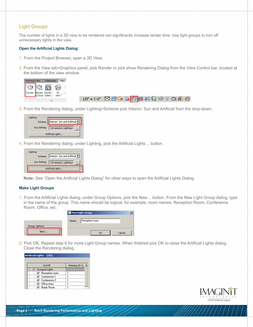
1. From the Project Browser, open a 3D View.
2. From the View tab>Graphics panel, pick Render or pick show Rendering Dialog from the View Control bar, located at the bottom of the view window.
3. From the Rendering dialog, under Lighting>Scheme pick Interior: Sun and Artificial from the drop-down.
4. From the Rendering dialog, under Lighting, pick the Artificial Lights… button.
Note: See “Open the Artificial Lights Dialog” for other ways to open the Artificial Lights Dialog.
Make Light Groups
1. From the Artificial Lights dialog, under Group Options, pick the New… button. From the New Light Group dialog, type in the name of the group. This name should be logical, for example, room names: Reception Room, Conference Room, Office, etc.
2. Pick OK. Repeat step 6 for more Light Group names. When finished pick OK to close the Artificial Lights dialog. Close the Rendering dialog.
Page 3 • Revit Rendering Performance and Lighting
Move Lights to Light Groups
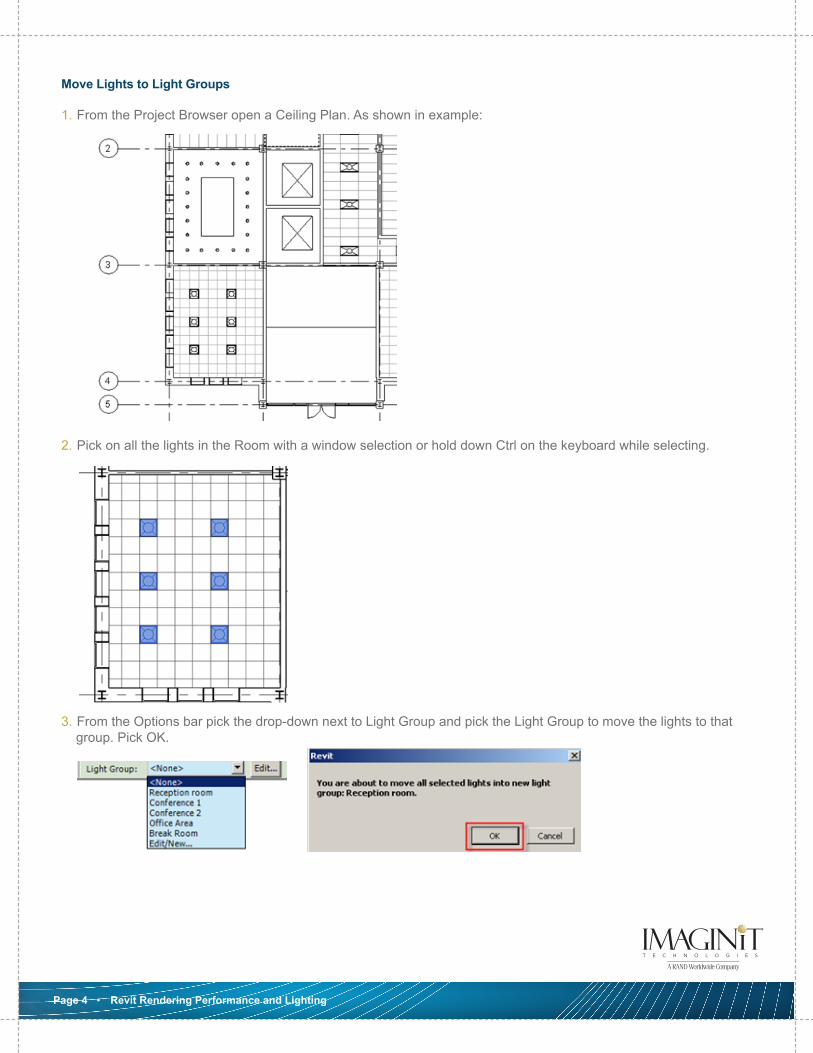
1. From the Project Browser open a Ceiling Plan. As shown in example:
2. Pick on all the lights in the Room with a window selection or hold down Ctrl on the keyboard while selecting.
3. From the Options bar pick the drop-down next to Light Group and pick the Light Group to move the lights to that group. Pick OK.
Page 4 • Revit Rendering Performance and Lighting
4. Repeat Step 8 and 9 for the other lights in each room as needed. Note: not all lights need to be in a Light Group, this depends on the view you’re going to render.
Note: Edit/New from the drop-down opens the Artificial Lights dialog, which allows you to make new Light Groups, rename, edit and delete Groups. You can also Move Lights Fixtures to Group name and Remove Light Fixtures from a Group.
Move Lights to Group from the Artificial Lights Dialog
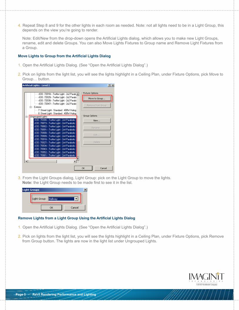
1. Open the Artificial Lights Dialog. (See “Open the Artificial Lights Dialog”.)
2. Pick on lights from the light list, you will see the lights highlight in a Ceiling Plan, under Fixture Options, pick Move to Group… button.
3. From the Light Groups dialog, Light Group: pick on the Light Group to move the lights. Note: the Light Group needs to be made first to see it in the list.
Remove Lights from a Light Group Using the Artificial Lights Dialog
1. Open the Artificial Lights Dialog. (See “Open the Artificial Lights Dialog”.)
2. Pick on lights from the light list, you will see the lights highlight in a Ceiling Plan, under Fixture Options, pick Remove from Group button. The lights are now in the light list under Ungrouped Lights.
Page 5 • Revit Rendering Performance and Lighting
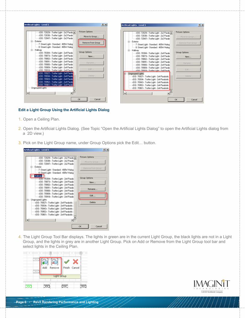
Edit a Light Group Using the Artificial Lights Dialog
1. Open a Ceiling Plan.
2. Open the Artificial Lights Dialog. (See Topic “Open the Artificial Lights Dialog” to open the Artificial Lights dialog from a 2D view.)
3. Pick on the Light Group name, under Group Options pick the Edit… button.
4. The Light Group Tool Bar displays. The lights in green are in the current Light Group, the black lights are not in a Light Group, and the lights in grey are in another Light Group. Pick on Add or Remove from the Light Group tool bar and select lights in the Ceiling Plan.
Page 6 • Revit Rendering Performance and Lighting
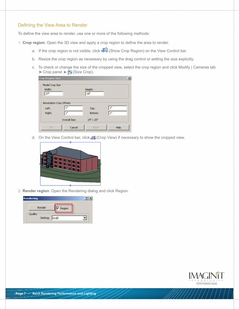
Defining the View Area to Render
To define the view area to render, use one or more of the following methods:
1. Crop region: Open the 3D view and apply a crop region to define the area to render.
a. If the crop region is not visible, click (Show Crop Region) on the View Control bar.
b. Resize the crop region as necessary by using the drag control or setting the size explicitly.
c. To check or change the size of the cropped view, select the crop region and click Modify | Cameras tab Crop panel (Size Crop).
d. On the View Control bar, click (Crop View) if necessary to show the cropped view.
2. Render region: Open the Rendering dialog and click Region.
Page 7 • Revit Rendering Performance and Lighting
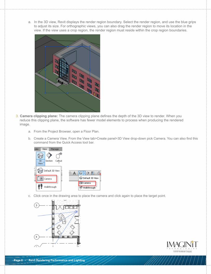
a. In the 3D view, Revit displays the render region boundary. Select the render region, and use the blue grips to adjust its size. For orthographic views, you can also drag the render region to move its location in the view. If the view uses a crop region, the render region must reside within the crop region boundaries.
3. Camera clipping plane: The camera clipping plane defines the depth of the 3D view to render. When you reduce this clipping plane, the software has fewer model elements to process when producing the rendered image.
a. From the Project Browser, open a Floor Plan.
b. Create a Camera View. From the View tab>Create panel>3D View drop-down pick Camera. You can also find this command from the Quick Access tool bar.
c. Click once in the drawing area to place the camera and click again to place the target point.
Page 8 • Revit Rendering Performance and Lighting
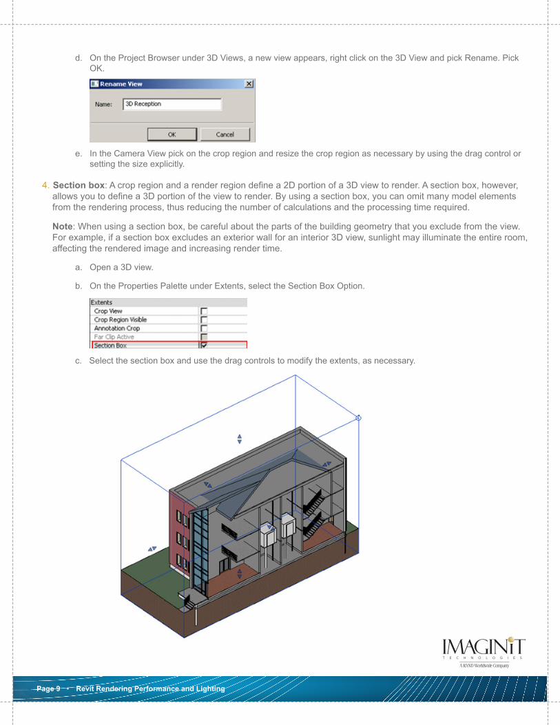
d. On the Project Browser under 3D Views, a new view appears, right click on the 3D View and pick Rename. Pick OK.
e. In the Camera View pick on the crop region and resize the crop region as necessary by using the drag control or setting the size explicitly.
4. Section box: A crop region and a render region define a 2D portion of a 3D view to render. A section box, however, allows you to define a 3D portion of the view to render. By using a section box, you can omit many model elements from the rendering process, thus reducing the number of calculations and the processing time required.
Note: When using a section box, be careful about the parts of the building geometry that you exclude from the view. For example, if a section box excludes an exterior wall for an interior 3D view, sunlight may illuminate the entire room, affecting the rendered image and increasing render time.
a. Open a 3D view.
b. On the Properties Palette under Extents, select the Section Box Option.
c. Select the section box and use the drag controls to modify the extents, as necessary.
Page 9 • Revit Rendering Performance and Lighting
d. To control visibility of the section box, in the Visibility/Graphics dialog (type V V on the keyboard), click the Annotation Categories tab. Clear the check box for Section Boxes, and click OK to hide the section box extents in the view.
Rendering and Lighting Settings
The amount of time required to generate the rendered image varies depending on many factors, such as the number of model elements and artificial lights, the complexity of the materials and the size or resolution of the image.
1. Exterior Rendering
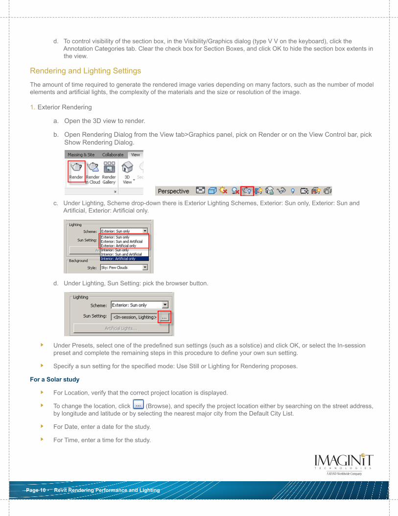
a. Open the 3D view to render.
b. Open Rendering Dialog from the View tab>Graphics panel, pick on Render or on the View Control bar, pick Show Rendering Dialog.
c. Under Lighting, Scheme drop-down there is Exterior Lighting Schemes, Exterior: Sun only, Exterior: Sun and Artificial, Exterior: Artificial only.
d. Under Lighting, Sun Setting: pick the browser button.
Under Presets, select one of the predefined sun settings (such as a solstice) and click OK, or select the In-session preset and complete the remaining steps in this procedure to define your own sun setting.
Specify a sun setting for the specified mode: Use Still or Lighting for Rendering proposes.
For a Solar study
For Location, verify that the correct project location is displayed.
To change the location, click (Browse), and specify the project location either by searching on the street address, by longitude and latitude or by selecting the nearest major city from the Default City List.
For Date, enter a date for the study.
For Time, enter a time for the study.
Page 10 • Revit Rendering Performance and Lighting
For a Lighting study
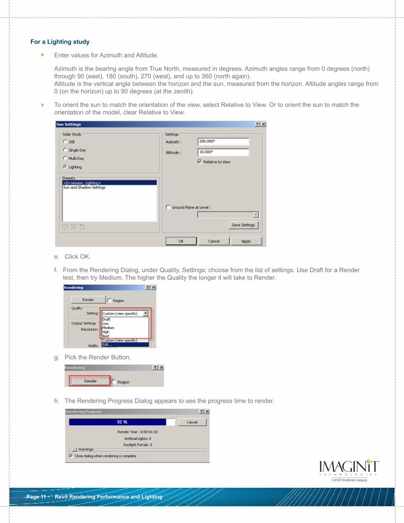
Enter values for Azimuth and Altitude.
Azimuth is the bearing angle from True North, measured in degrees. Azimuth angles range from 0 degrees (north) through 90 (east), 180 (south), 270 (west), and up to 360 (north again). Altitude is the vertical angle between the horizon and the sun, measured from the horizon. Altitude angles range from 0 (on the horizon) up to 90 degrees (at the zenith).
To orient the sun to match the orientation of the view, select Relative to View. Or to orient the sun to match the orientation of the model, clear Relative to View.
e. Click OK.
f. From the Rendering Dialog, under Quality, Settings: choose from the list of settings. Use Draft for a Render test, then try Medium. The higher the Quality the longer it will take to Render.
g. Pick the Render Button.
h. The Rendering Progress Dialog appears to see the progress time to render.
Page 11 • Revit Rendering Performance and Lighting
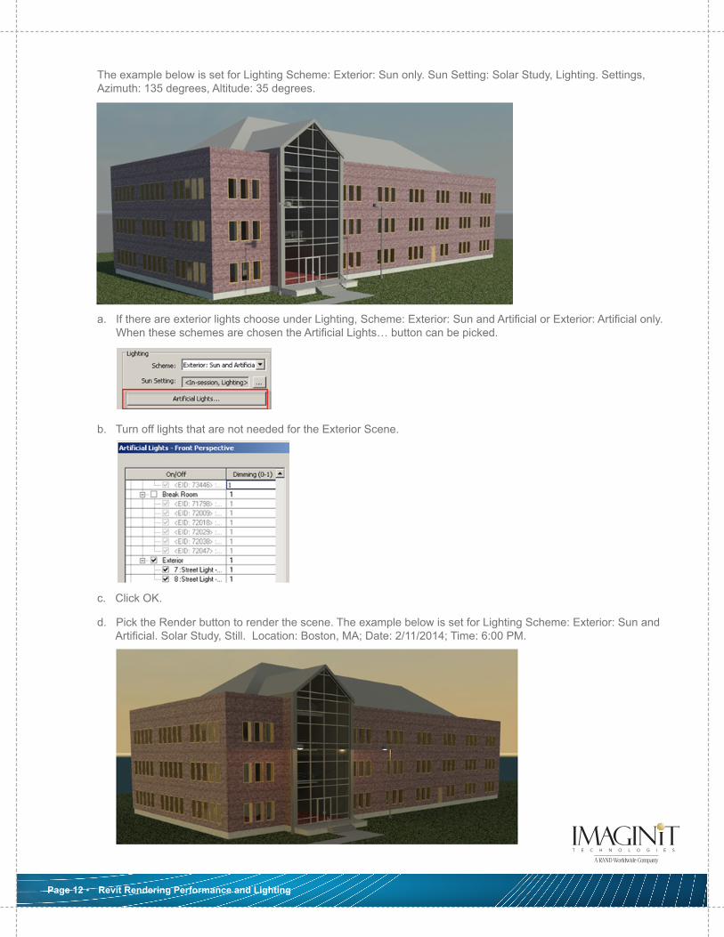
The example below is set for Lighting Scheme: Exterior: Sun only. Sun Setting: Solar Study, Lighting. Settings, Azimuth: 135 degrees, Altitude: 35 degrees.
a. If there are exterior lights choose under Lighting, Scheme: Exterior: Sun and Artificial or Exterior: Artificial only. When these schemes are chosen the Artificial Lights… button can be picked.
b. Turn off lights that are not needed for the Exterior Scene.
c. Click OK.
d. Pick the Render button to render the scene. The example below is set for Lighting Scheme: Exterior: Sun and Artificial. Solar Study, Still. Location: Boston, MA; Date: 2/11/2014; Time: 6:00 PM.
Page 12 • Revit Rendering Performance and Lighting
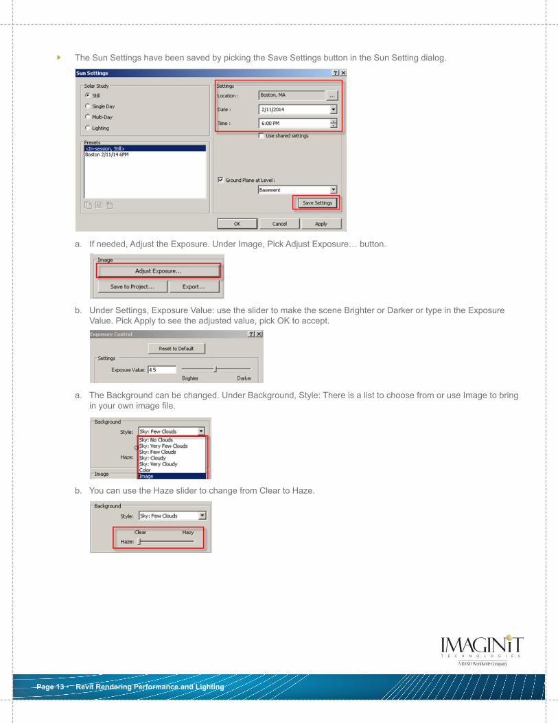
The Sun Settings have been saved by picking the Save Settings button in the Sun Setting dialog.
a. If needed, Adjust the Exposure. Under Image, Pick Adjust Exposure… button.
b. Under Settings, Exposure Value: use the slider to make the scene Brighter or Darker or type in the Exposure Value. Pick Apply to see the adjusted value, pick OK to accept.
a. The Background can be changed. Under Background, Style: There is a list to choose from or use Image to bring in your own image file.
b. You can use the Haze slider to change from Clear to Haze.
Page 13 • Revit Rendering Performance and Lighting
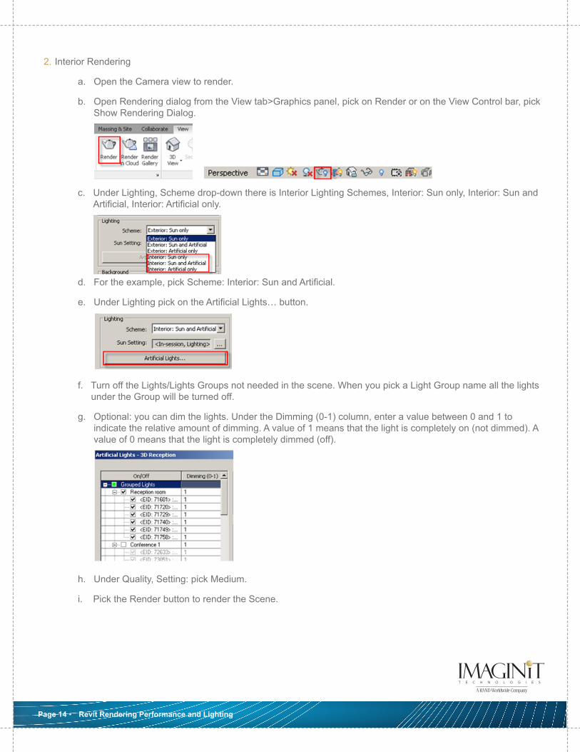
2. Interior Rendering
a. Open the Camera view to render.
b. Open Rendering dialog from the View tab>Graphics panel, pick on Render or on the View Control bar, pick Show Rendering Dialog.
c. Under Lighting, Scheme drop-down there is Interior Lighting Schemes, Interior: Sun only, Interior: Sun and Artificial, Interior: Artificial only.
d. For the example, pick Scheme: Interior: Sun and Artificial.
e. Under Lighting pick on the Artificial Lights… button.
f. Turn off the Lights/Lights Groups not needed in the scene. When you pick a Light Group name all the lights under the Group will be turned off.
g. Optional: you can dim the lights. Under the Dimming (0-1) column, enter a value between 0 and 1 to indicate the relative amount of dimming. A value of 1 means that the light is completely on (not dimmed). A value of 0 means that the light is completely dimmed (off).
h. Under Quality, Setting: pick Medium.
i. Pick the Render button to render the Scene.
Page 14 • Revit Rendering Performance and Lighting
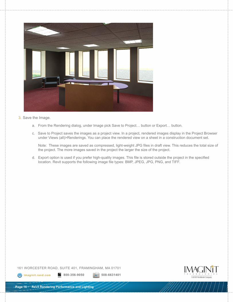
3. Save the Image.
a. From the Rendering dialog, under Image pick Save to Project… button or Export… button.
c. Save to Project saves the images as a project view. In a project, rendered images display in the Project Browser under Views (all)>Renderings. You can place the rendered view on a sheet in a construction document set.
Note: These images are saved as compressed, light-weight JPG files in draft view. This reduces the total size of the project. The more images saved in the project the larger the size of the project.
d. Export option is used if you prefer high-quality images. This file is stored outside the project in the specified location. Revit supports the following image file types: BMP, JPEG, JPG, PNG, and TIFF.
Page 16 • Revit Rendering Performance and Lighting
161 WORCESTER ROAD, SUITE 401, FRAMINGHAM, MA 01701
imaginit.rand.com 800-356-9050 508-6631401