Embed Size (px)
Citation preview
www.cst.com1
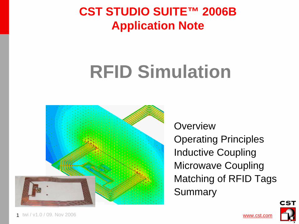
OverviewOperating PrinciplesInductive CouplingMicrowave CouplingMatching of RFID Tags Summary
twi / v1.0 / 09. Nov 2006
CST STUDIO SUITE™ 2006BApplication Note
RFID Simulation
www.cst.com2
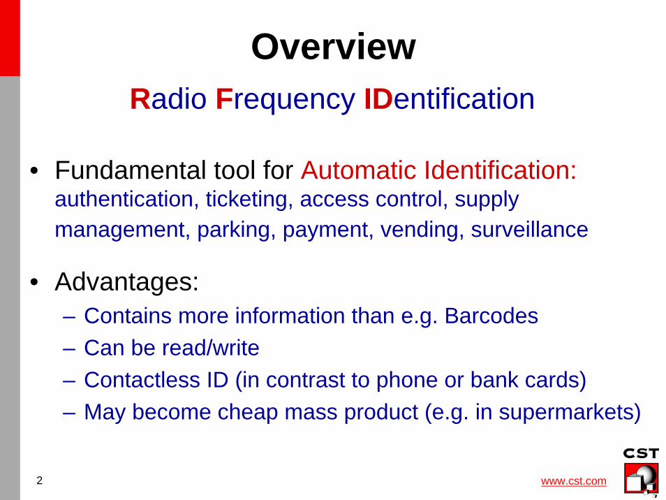
Overview
• Fundamental tool for Automatic Identification:authentication, ticketing, access control, supplymanagement, parking, payment, vending, surveillance
• Advantages: – Contains more information than e.g. Barcodes– Can be read/write– Contactless ID (in contrast to phone or bank cards)– May become cheap mass product (e.g. in supermarkets)
Radio Frequency IDentification
www.cst.com3
General Principle
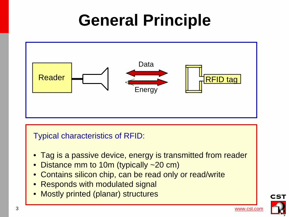
Typical characteristics of RFID:
• Tag is a passive device, energy is transmitted from reader• Distance mm to 10m (typically ~20 cm)• Contains silicon chip, can be read only or read/write• Responds with modulated signal• Mostly printed (planar) structures
Reader RFID tag
Data
Energy
www.cst.com4
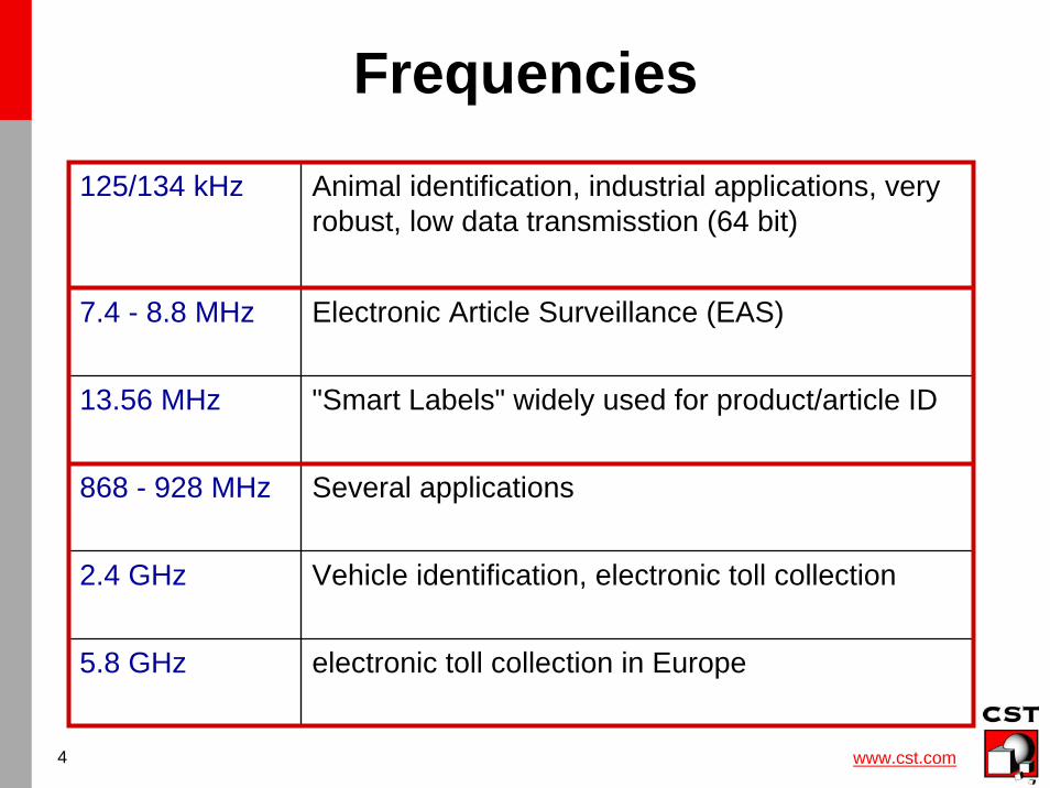
Frequencies
125/134 kHz Animal identification, industrial applications, veryrobust, low data transmisstion (64 bit)
7.4 - 8.8 MHz Electronic Article Surveillance (EAS)
13.56 MHz "Smart Labels" widely used for product/article ID
868 - 928 MHz Several applications
2.4 GHz Vehicle identification, electronic toll collection
5.8 GHz electronic toll collection in Europe
www.cst.com5
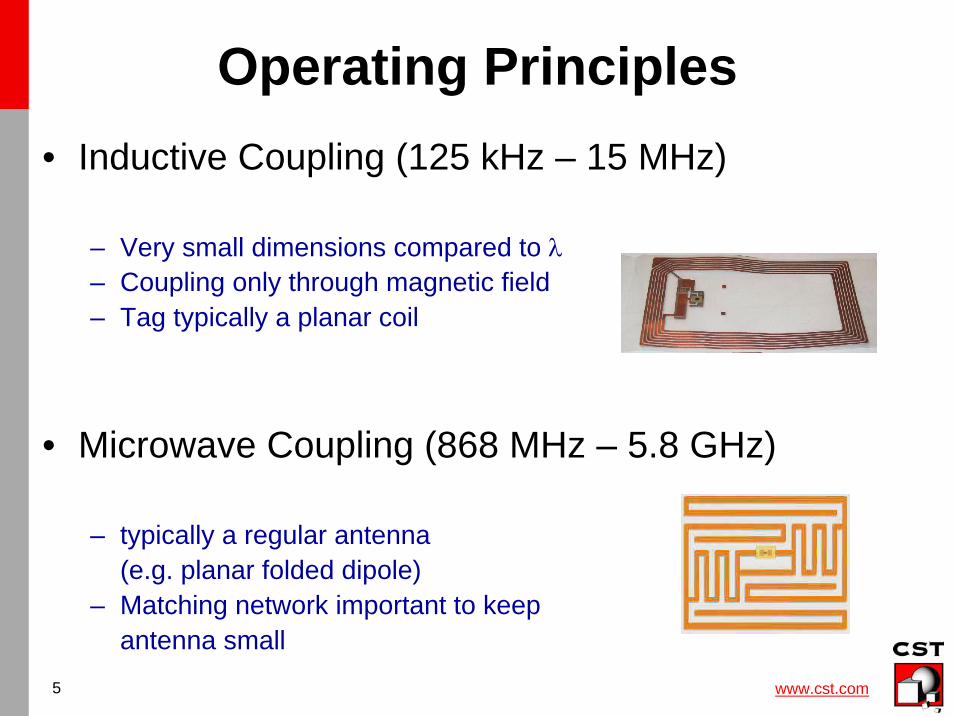
Operating Principles• Inductive Coupling (125 kHz – 15 MHz)
– Very small dimensions compared to λ– Coupling only through magnetic field– Tag typically a planar coil
• Microwave Coupling (868 MHz – 5.8 GHz)
– typically a regular antenna(e.g. planar folded dipole)
– Matching network important to keepantenna small
www.cst.com6
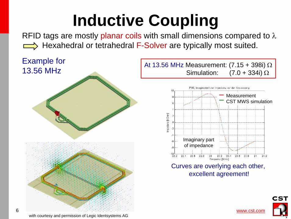
Inductive CouplingRFID tags are mostly planar coils with small dimensions compared to λ
Hexahedral or tetrahedral F-Solver are typically most suited.
Example for13.56 MHz
with courtesy and permission of Legic Identsystems AG
At 13.56 MHz Measurement: (7.15 + 398i) ΩSimulation: (7.0 + 334i) Ω
MeasurementCST MWS simulation
Imaginary partof impedance
Curves are overlying each other, excellent agreement!
www.cst.com7
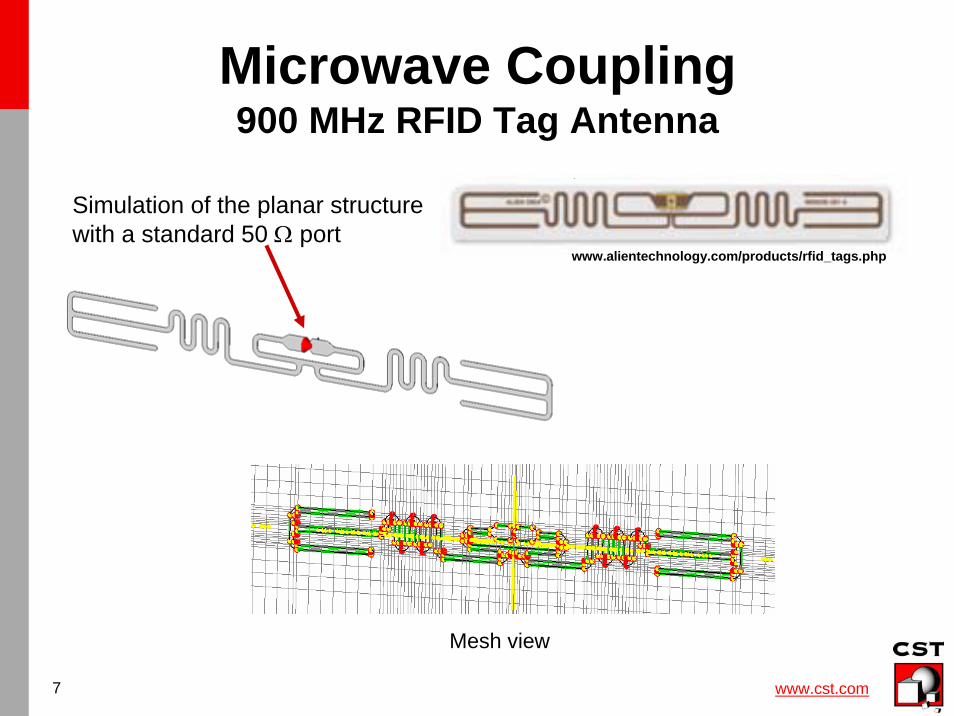
Microwave Coupling900 MHz RFID Tag Antenna
www.alientechnology.com/products/rfid_tags.php
Simulation of the planar structurewith a standard 50 Ω port
Mesh view
www.cst.com8
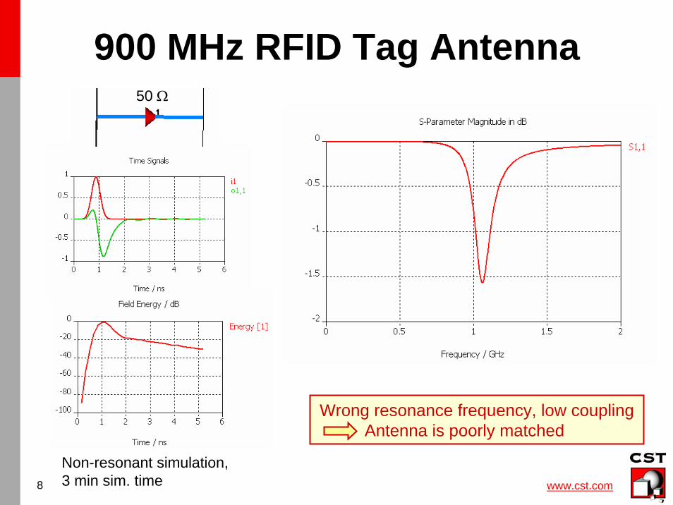
50 Ω
Non-resonant simulation, 3 min sim. time
Wrong resonance frequency, low couplingAntenna is poorly matched
900 MHz RFID Tag Antenna
www.cst.com9
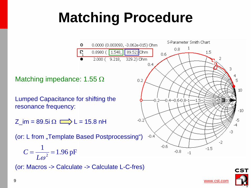
Matching Procedure
Matching impedance: 1.55 Ω
Lumped Capacitance for shifting theresonance frequency:
Z_im = 89.5i Ω L = 15.8 nH
(or: L from „Template Based Postprocessing“)
(or: Macros -> Calculate -> Calculate L-C-fres)
pF 96.112 ==
ωLC
www.cst.com10
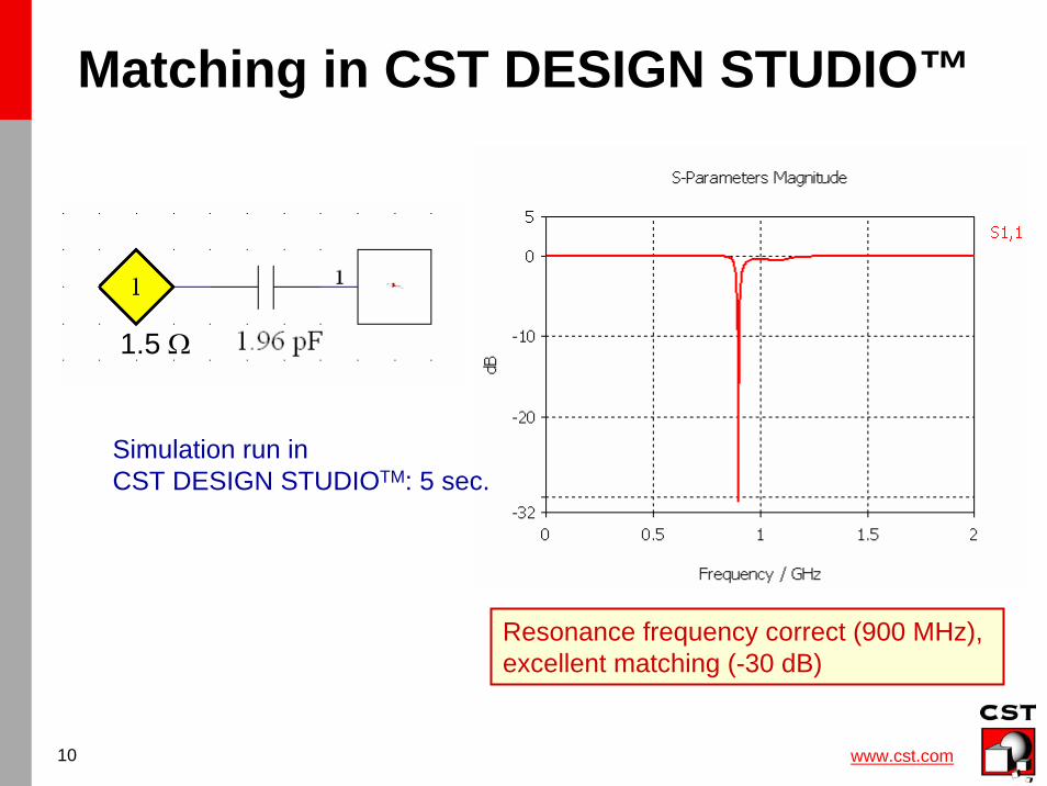
Matching in CST DESIGN STUDIO™
1.5 Ω
Resonance frequency correct (900 MHz), excellent matching (-30 dB)
Simulation run in CST DESIGN STUDIOTM: 5 sec.
www.cst.com11
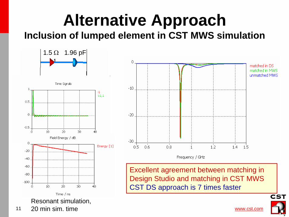
Alternative ApproachInclusion of lumped element in CST MWS simulation
Resonant simulation, 20 min sim. time
Excellent agreement between matching in Design Studio and matching in CST MWSCST DS approach is 7 times faster
1.5 Ω 1.96 pF
www.cst.com12
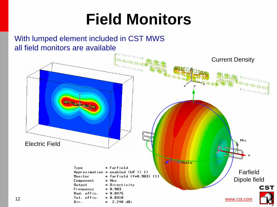
Field Monitors
Current Density
Electric Field
FarfieldDipole field
With lumped element included in CST MWS all field monitors are available
www.cst.com13
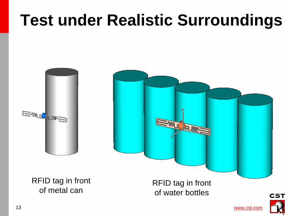
Test under Realistic Surroundings
RFID tag in front of metal can
RFID tag in front of water bottles
www.cst.com14
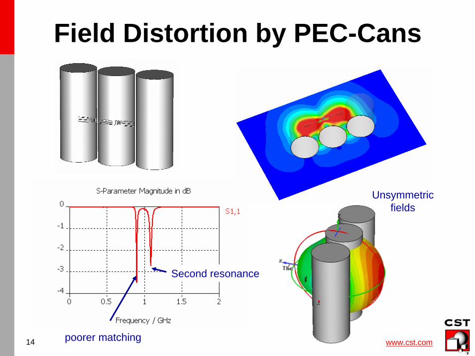
Field Distortion by PEC-Cans
poorer matching
Second resonance
Unsymmetricfields
www.cst.com15
Summary
• RFID is a general concept using different technical principals
• CST complete technology approach offersbest solution for each case– Frequency Domain / CST EMS for coil type– Transient Simulator for microwave type
• Tags often contain lumped elements– Possible in both CST MWS or CST DS– CST DS typically more efficient