Embed Size (px)
Citation preview
Proceedings of the 1st International and 16th National Conference on Machines and Mechanisms (iNaCoMM2013), IIT Roorkee, India, Dec 18-20 2013
Ride comfort and Vehicle handling of Quarter Car Model Using SIMULINK and Bond Graph
Anirban. C. Mitra Department of Mechanical Engineering
M.E.S. College of Engineering Pune, India
Nilotpal Benerjee Department of Mechanical Engineering
National Institute of Technology Durgapur, India
Abstract—Suspension system design is always been a challenging task for the automobile designers in view of multiple control parameters, complex objectives and disturbances which are stochastic in nature. To maintain simultaneously a high standard of ride comfort and improved vehicle handling under all driving conditions is a necessity for good suspension design. These conflicting parameters pose a problem of a judicial compromise between these two and make the problem more complex. The present work aims at developing and applying a systematic methodology leading to optimum combinations of the suspension damping and stiffness parameters of a ground vehicle subjected to road excitation. A 4 DOF quarter car model has been developed to study important effects on Passenger body (Head, Thorax-pelvis), seating on a cushion seat using a Bondgraph model and SIMULINK model separately results of which are in good agreement with each other and also matching with the real life expectations. The effects of variations of suspension stiffness and damping coefficient on ride comfort, road holding and head displacement has been studied over wide range of road bump.
Keyword: 4 DOF Quarter Car Model, Ride comfort, Road Holding, Head displacement, Bondgraph, SIMULINK
I. INTRODUCTION Passenger comfort is a key issue in design and
manufacture of modern automobiles. Design of advanced suspension systems is one of the requirements, which provide a comfortable ride by absorbing the road disturbances as well as maintain the vehicle stability. A good amount of research activities has been directed to improve the ride comfort specially over the last decade. In automobiles, motions are experienced by the harmful effects of vibrations due to road irregularities and have a pivotal role in determining passenger's comfort.
Vibration may affect the body in a number of ways. Notably, passive movement of vibration through the abdominal wall causes the hyperventilation, disorders of the back like back pain, osteoarthritis, slipping of disc etc. have commonly been associated with exposure to vibration as shown by Kjellberg [1]. Griffin et al [2] have demonstrated the effects of road excitation on comfort and road holding capability. Tewari et. al. [3] and Gundogdu [4] presented an optimization of a four-degree
of freedom quarter car seat and suspension system to determine a set of parameters to achieve the best performance for the driver's seat. As per ISO 2631-1, 1997, passenger comfort principally depends on root mean square (RMS) value of acceleration and the frequency of vibrations acted on his body [5]. Wong. [6], through his elaborative research have established a complex vibration phenomenon of multiple degrees of freedom vehicle suspension system. For analyzing the vibration characteristics of the vehicle, governing equations of motion have been formulated for the multi degree of freedom system. Most of the previous studies on the subject have dealt with 2 DOF Quarter car models possessing a sprung mass and unsprung mass. However, there remains ample scope of studying important effects on Passenger body (Head, Thorax-pelvis), on a cushion seat considering a 4 DOF quarter car model which has been set as a focus of the present work.
II. MATHEMATICAL MODEL Construction of human body models for the
simulation of vibration exposure characteristics has been explored by Tantawy [7]. Fig.01 illustrates the physical model of a four degree of freedom Quarter car model with driver seated on a cushion seat .The aim of this study is to maximize the ride comfort, road holding as well as to minimize the displacement of head and upper body. Basically the performance of the suspension system considering linear lumped mass parameter model is used to obtain a qualitative insight into the influences of stiffness of the suspension spring and damping of the shock absorbers on the vehicle vibration. In this model, it is assumed that the tire is a linear spring with a stiffness of Kt.
1
Proceedings of the 1st International and 16th National Conference on Machines and Mechanisms (iNaCoMM2013), IIT Roorkee, India, Dec 18-20 2013
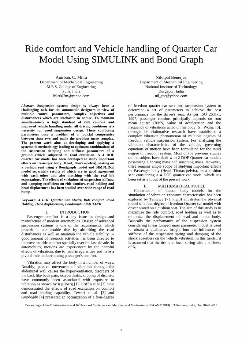
Fig.01 Quarter car model with driver seated on a cushion seat.
The constants MS and MU are the sprung and unsprung mass of the vehicle considering one fourth of the total vehicle mass. The damping and spring coefficients of the suspension are denoted by CS and KS respectively. The cushion elastic properties are also considered as a spring and a dashpot with respective constants of Kc and Cc. The driver is represented by a 2 DOF lumped masses as lower body and head. The upper part of the body is also connected to the lower part through a spring and a dashpot combination with constants, Kp and Cp respectively. Furthermore, movement of the system is considered in the vertical direction only as input excitation due to road bump. At a particular point of time displacement of the sprung and unsprung mass ZS and ZU are measured due to the sinusoidal excitation ZY from the road bump. The variables ZB and ZH represent the possible displacements of the lower body and head. The all vertical displacements are measured from their static equilibrium positions so that we can neglect the gravity term while writing the equation of motion for the masses.
As per Newton’s second law of motion the equations for the system can be described by the following differential equations from their static equilibrium positions are as follows:-
( ) ( )BHppHH ZZKCZM −−−−= BH ZZ ɺɺɺɺ (1)
( ) ( )( ) ( )SBCSBC
BHppBB
ZZKZZC
ZZKCZM
−−−−
−+−=ɺɺ
ɺɺɺɺBH ZZ
(2)
( ) ( )( ) ( )USSUSS
SBCcSS
ZZKZZC
ZZKCZM
−−−−
−+−=ɺɺ
ɺɺɺɺSB ZZ
(3)
( ) ( )( )YUt
USSUSSUU
ZZK
ZZKZZCZM
−−
−+−= ɺɺɺɺ
(4)
The above linear differential equation set is consisting of four system variables, ZH, ZB, ZS, and ZU for a given road excitation Z�. The variable with single dot at the top specifies single derivative i.e. velocity and double dot specifies double derivative i.e. acceleration of corresponding displacement. The driver mass is taken as M= 65 kg, while the mass of upper body and head is taken asM� � ��
�, and the mass of lower bodyand seat is
taken asM� � ��
� as apparent masses, Tewari [3]. The
other parameters used in the simulations are as follows Gundogdu [4],
Road Profile:
The effect of a sinusoidal road excitation shown in Fig.02 on the ride comfort, road holding and displacement of the head has been computed for the various bump width L with different vehicle velocity v. For an absolute time frame t represents the simulation time when wheel is just approaching a bump with a distance d. The mathematical expression of bump excitation on wheel is as follows, Banerjee [8]:
Sprung Mass MS 240 Kgs.
Unsprung Mass MU 36 Kgs.
Mass of Upper body and Head
MH 20 Kgs.
Mass of Lower body and Seat
MB 45 Kgs.
Spring stiffness and Damping coefficient of Thorax and Pelvis
Kp, Cp
45005.3N/m 1360 Ns/m
Spring stiffness and Damping coefficient of Seat cushion
Kc, Cc
20000N/m 1649.03 Ns/m
Spring stiffness of Tire K t 160000 N/m
2
Proceedings of the 1st International and 16th National Conference on Machines and Mechanisms (iNaCoMM2013), IIT Roorkee, India, Dec 18-20 2013
ZY = 0 when t < �
(5)
� hsin �t � �
� for �
� t � ���
=0 when t > ���
The flow to the wheel is found out by differentiating ZY w.r.t time, as Source of Flow (SF) in bond graph.
YZɺ = 0 when t < �
(6)
=
�cos
�t � �
� for �
� t � ���
=0 when t > ���
III. SIMULATION
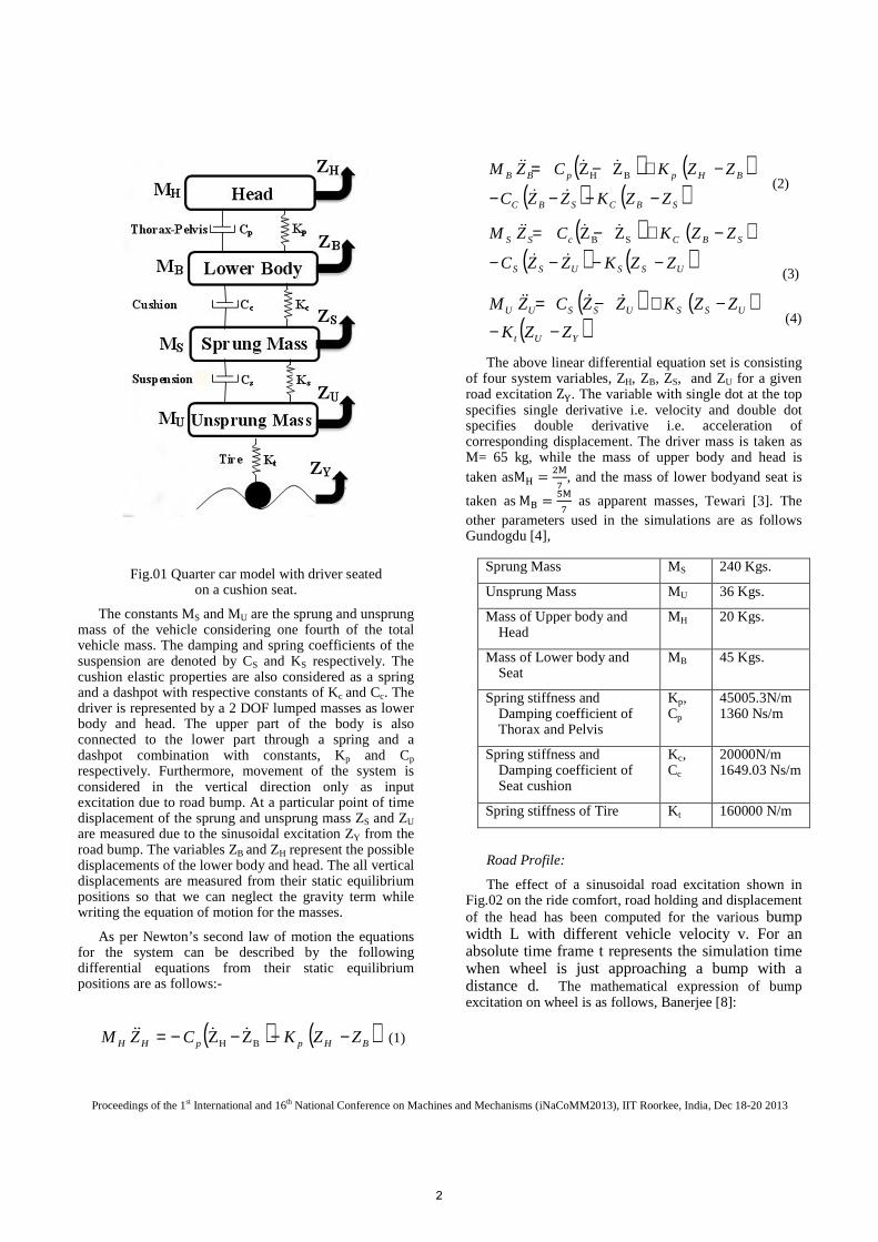
Bond graph model: A Bondgraph model of quarter car with driver seated
on a cushion seat has been created (Fig.03). Bondgraph is a portrayal of exchange of power between various elements maintaining the constraints of the system ensured through the use of junction elements 0 and 1. In Bondgraph modeling a system is resolved into basic elements i.e. compliances element, dissipative element and inertia element represented by C, R and I respectively. External forces and velocities are represented by source elements SE (source of effort) and SF (source of flow) respectively. These sources are considered as sort of reservoir, which can supply any amount of effort or flow as the system demands. The above elements are connected by bonds (lines) representing exchange of power. Each bond is associated with two factors of power. Effort (force, voltage, pressure, temperature etc.), e and flows (velocity, current, volume flow rate, entropy change rate etc.), f. Driver is considered as a lumped mass modeled as I element appended to a 1 junction through bond number 2. Similarly, I elements are appended through bond numbers 4, 7 and 10 to three different 1-junctions which model lower body & seat, sprung mass and unsprung mass as lumped masses respectively. Body stiffness and damping has been modeled as C element and R element appended
to a 1-juntion through bond numbers 17 and 18 respectively to take the difference of flows between driver head and seat cushion at the 0-junction through bond number 12.
Fig.03 Bondgraph model of quarter car model with driver seated on cushion seat
Cushion stiffness & damping and Suspension stiffness & damping are modeled similarly. Tire stiffness is modeled by C element on bond number 16. Road input is modeled with the SF element on bond 15. Two flow activated C elements (when a bond is activated for flow only it does not act as a power bond but gives only flow in that bond) appended to bonds 23 and 24, which senses only flows, and indicates displacement of unsprung mass, ZU and Head displacement ZH respectively.
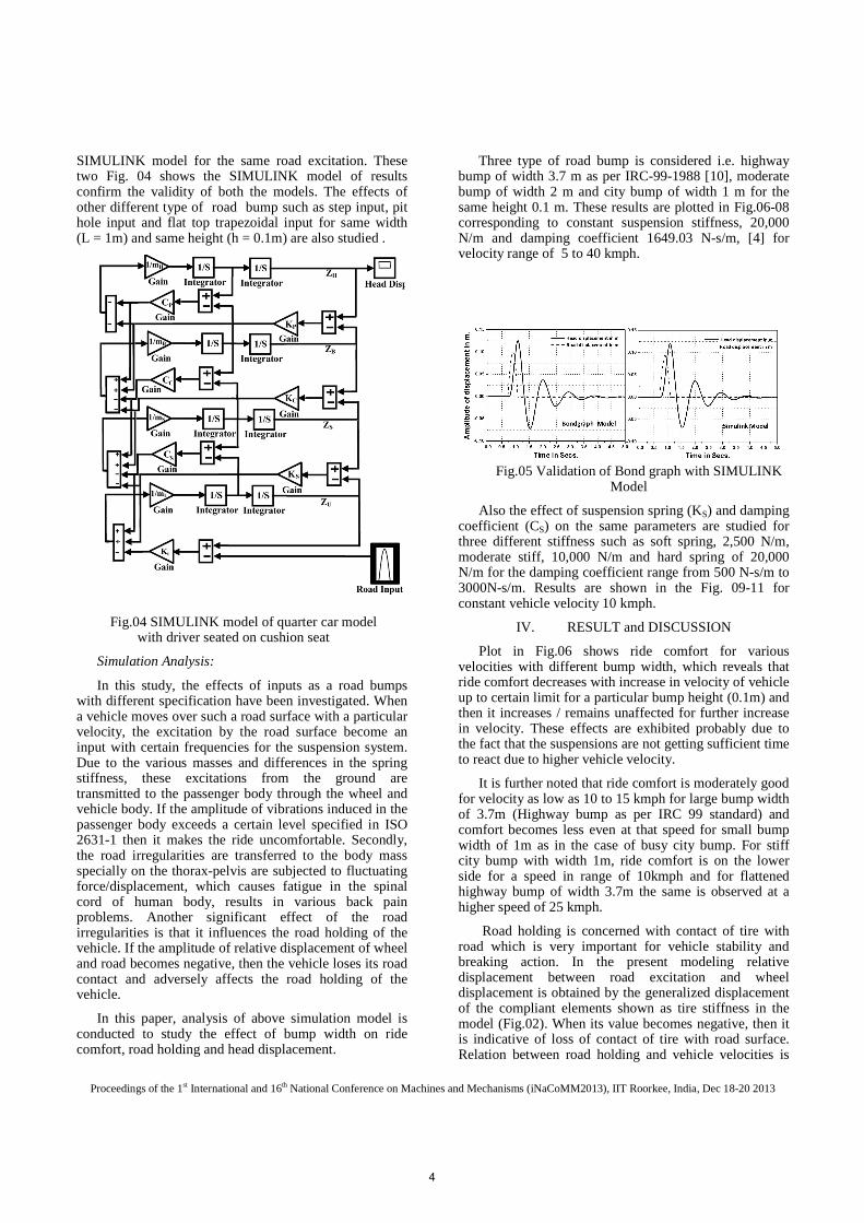
SIMULINK Model:
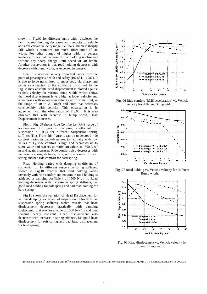
Quarter car model with driver seated on a cushion seat as shown in Fig.01, considering the governing equations (1-4). In Fig. 05, two plots side by side are placed for comparison. One on the left hand side has been obtained by simulation of the Bondgraph model on simulation software SYMBOLS SHAKTI and the other on the right-hand side has been obtained from simulation of
Fig.02 Road profile of height 0.1m.
3
Proceedings of the 1st International and 16th National Conference on Machines and Mechanisms (iNaCoMM2013), IIT Roorkee, India, Dec 18-20 2013
SIMULINK model for the same road excitation. These two Fig. 04 shows the SIMULINK model of results confirm the validity of both the models. The effects of other different type of road bump such as step input, pit hole input and flat top trapezoidal input for same width (L = 1m) and same height (h = 0.1m) are also studied .
Fig.04 SIMULINK model of quarter car model with driver seated on cushion seat
Simulation Analysis:
In this study, the effects of inputs as a road bumps with different specification have been investigated. When a vehicle moves over such a road surface with a particular velocity, the excitation by the road surface become an input with certain frequencies for the suspension system. Due to the various masses and differences in the spring stiffness, these excitations from the ground are transmitted to the passenger body through the wheel and vehicle body. If the amplitude of vibrations induced in the passenger body exceeds a certain level specified in ISO 2631-1 then it makes the ride uncomfortable. Secondly, the road irregularities are transferred to the body mass specially on the thorax-pelvis are subjected to fluctuating force/displacement, which causes fatigue in the spinal cord of human body, results in various back pain problems. Another significant effect of the road irregularities is that it influences the road holding of the vehicle. If the amplitude of relative displacement of wheel and road becomes negative, then the vehicle loses its road contact and adversely affects the road holding of the vehicle.
In this paper, analysis of above simulation model is conducted to study the effect of bump width on ride comfort, road holding and head displacement.
Three type of road bump is considered i.e. highway bump of width 3.7 m as per IRC-99-1988 [10], moderate bump of width 2 m and city bump of width 1 m for the same height 0.1 m. These results are plotted in Fig.06-08 corresponding to constant suspension stiffness, 20,000 N/m and damping coefficient 1649.03 N-s/m, [4] for velocity range of 5 to 40 kmph.
Also the effect of suspension spring (KS) and damping coefficient (CS) on the same parameters are studied for three different stiffness such as soft spring, 2,500 N/m, moderate stiff, 10,000 N/m and hard spring of 20,000 N/m for the damping coefficient range from 500 N-s/m to 3000N-s/m. Results are shown in the Fig. 09-11 for constant vehicle velocity 10 kmph.
IV. RESULT and DISCUSSION
Plot in Fig.06 shows ride comfort for various velocities with different bump width, which reveals that ride comfort decreases with increase in velocity of vehicle up to certain limit for a particular bump height (0.1m) and then it increases / remains unaffected for further increase in velocity. These effects are exhibited probably due to the fact that the suspensions are not getting sufficient time to react due to higher vehicle velocity.
It is further noted that ride comfort is moderately good for velocity as low as 10 to 15 kmph for large bump width of 3.7m (Highway bump as per IRC 99 standard) and comfort becomes less even at that speed for small bump width of 1m as in the case of busy city bump. For stiff city bump with width 1m, ride comfort is on the lower side for a speed in range of 10kmph and for flattened highway bump of width 3.7m the same is observed at a higher speed of 25 kmph.
Road holding is concerned with contact of tire with road which is very important for vehicle stability and breaking action. In the present modeling relative displacement between road excitation and wheel displacement is obtained by the generalized displacement of the compliant elements shown as tire stiffness in the model (Fig.02). When its value becomes negative, then it is indicative of loss of contact of tire with road surface. Relation between road holding and vehicle velocities is
Fig.05 Validation of Bond graph with SIMULINK Model
4
Proceedings of the 1st International and 16th National Conference on Machines and Mechanisms (iNaCoMM2013), IIT Roorkee, India, Dec 18-20 2013
shown in Fig.07 for different bump width discloses the fact that road holding decreases with velocity of vehicle and after certain velocity range, i.e. 25-30 kmph it sharply falls which is prominent for much stiffer bump of 1m width. For other bumps of higher width a general tendency of gradual decrease of road holding is observed without any sharp change until speed of 40 kmph. Another observation is that road holding decreases with decrease with bump width, as expected in general.
Head displacement is very important factor from the point of passenger’s health and safety (BS 6841- 1987). It is due to force transmitted to upper body via thorax and pelvis as a reaction to the excitation from road. In the Fig.08 max absolute head displacement is plotted against vehicle velocity for various bump width, which shows that head displacement is very high at lower velocity and it increases with increase in velocity up to some limit, in the range of 10 to 20 kmph and after that decreases considerably with velocity. This observation is in agreement with the observation of Fig.06. It is also observed that with decrease in bump width, Head Displacement increases.
Plot in Fig. 09 shows Ride Comfort i.e. RMS value of acceleration for various damping coefficient of suspension oil (CS) for different Suspension spring stiffness (KS). From this figure it can be understood ride comfort varies in bathtub nature, i.e. initially with low values of CS, ride comfort is high and decreases up to some value and reaches to minimum values at 1500 N-s / m and again increases. Ride comfort also decreases with increase in spring stiffness, i.e. good ride comfort for soft spring and bad ride comfort for hard spring.
Road Holding varies with damping coefficient of suspension oil for different Suspension spring stiffness, shown in Fig.10 exposes that road holding varies inversely with ride comfort and maximum road holding is achieved at damping coefficient of 1500 N-s / m. Road holding decreases with increase in spring stiffness, i.e. good road holding for soft spring and bad road holding for hard spring.
Fig.11 shows the variation of Head Displacement for various damping coefficient of suspension oil for different suspension spring stiffness, which reveals that head displacement decreases drastically with damping coefficient, till it reaches a value of 1500 N-s / m and then remains nearly constant. Head displacement also decreases with increase in spring stiffness, i.e. good head displacement for soft spring and bad head displacement for hard spring.
Fig. 06 Ride comfort (RMS acceleration) vs. Vehicle velocity for different Bump width.
Fig. 07 Road holding vs. Vehicle velocity for different Bump width.
Fig. 08 Head displacement vs. Vehicle velocity for different Bump width.
5
Proceedings of the 1st International and 16th National Conference on Machines and Mechanisms (iNaCoMM2013), IIT Roorkee, India, Dec 18-20 2013
Fig. 09 Ride comfort (RMS acceleration) vs. Damping coefficient for different spring stiffness
Fig. 10 Road holding vs. Damping coefficient for different spring stiffness.
Fig. 11 Head displacement vs. Damping coefficient for different spring stiffness.
V. CONCLUSION
From the above it is observed that the velocity within the band of 5 to 15 kmph while negotiating a bump reveals important correlation among the factors related to ride comfort, road holding and head displacement with respect to various widths of the bump. That relation can be summarized as ride comfort and head displacement is in the higher range for a considerably good road holding. It is obvious to get a good ride comfort and less head displacement, some amount of road holding may have to be sacrificed. Also for wider (Highway) bump, ride comfort and road holding is very good whereas for negotiating a city bump of less width above conditions deteriorates.
Also for different values of spring stiffness, Ks and damping coefficient, Cs it can be concluded that, better ride comfort and road holding is observed for CS=1500 N-s / m. and Ks=2500 N/m at the cost of high head displacement and more settling time.
VI. FUTURE SCOPE
There is enough scope for further studies on this topic, as Semi-active and Active suspension system can be compared with this Passive system. Some evolutionary optimization techniques, like Genetic Algorithm (GA) can also be used to optimize the multiobjective functions as ride comfort and road holding.
VII. REFERANCES
[1] Kjellberg, A. “Psychological aspects of occupational vibration”, (1990), Scandinavian Journal of Work and Environmental Health, 16 (Suppl. 1), 39-43
[2] M J Griffin, “Handbook of Human Vibration”, (1996), Academic press, London Publication, ISBN-10: 0123030412
[3] Tewari, V.K., Prasad, N., “Three-dof modeling of tractor seat operator system”, (1999), Journal of Terramechanics 36, 207–219.
[4] O Gundogdu, “Optimal seat and suspension design for a quarter car with driver model using genetic algorithms”, (2007), International Journal of Industrial Ergonomics, Elsevier.
[5] ISO: 2631-1, 1997, “Mechanical vibration and shock - Evaluation of human exposure to whole-body vibration”
[6] Wong.J.Y, “Theory of Ground Vehicles”, (2008), John Wiley & Sons, New York. ISBN-10: 0470170387.
[7] Tantawy. M. Farid, Ashraf Salah, Wael Abbas, “Design of Optimal Linear Suspension for Quarter Car with Human Model using Genetic Algorithms”,(2011), Journal of Applied Sciences Research, 7(11): 1709-1720, ISSN 1819-544X.
[8] Banerjee Nilotpal, De Jagannath “Effects of Excitations from Road on Suspensions of a Motorcycle and Ride Comfort”, The Bulletin of Engineering and Science.(ISSN 09747176), Vol. 2, No. 2. September 2007, Page: 1-7
[9] British Standards Institution. British standard guide to measurement and evaluation of human exposure to whole body mechanical vibration and repeated shock, BS 6841- 1987.
[10] IRC-99-1988: “Tentative guidelines on the provision of speed breakers for control of vehicular speeds on minor roads” published by The Indian Road Congress.
6