Embed Size (px)
Citation preview
INSTALLATION AND SERVICE MANUAL
FOR
LANCER ICE COOLED DISPENSER
REV: 05/22/98P.N. 28–0058/03
This manual supersedes Installation and Service Manual, 28-0058/02, dated 10/17/97
SERIES 2300 -- DROP INSERIES 2400 -- FREE STANDING
• FAX ENGINEERING: • 210-310-7096 •"Lancer" is the registered trademark of Lancer • Copyright — 1998 by Lancer, all rights reserved.
Please refer to the Lancer web site (www.lancercorp.com) forinformation relating to Lancer Installation and Service Manuals,Instruction Sheets, Technical Bulletins, Service Bulletins, etc.
6655 LANCER BLVD. • SAN ANTONIO, TEXAS 78219 USA • (210) 310-7000FAX SALES
• NORTH AMERICA – 210-310-7245 • INTERNATIONAL SALES – 210-310-7242 • CUSTOMER SERVICE – 210-310-7242 •• LATIN AMERICA – 210-310-7245 • EUROPE – 32-2-755-2399 • PACIFIC – 61-8-8268-1978 •
TABLE OF CONTENTS
TABLE OF CONTENTS......................................................................................................................................iSPECIFICATIONS...............................................................................................................................................i1. INSTALLATION OF LANCER ICE COOLED DISPENSER........................................................................1
1.1 RECEIVING........................................................................................................................................11.2 UNPACKING ......................................................................................................................................11.3 SELECTING A COUNTER LOCATION..............................................................................................11.4 WATER SUPPLY................................................................................................................................11.5 ELECTRICAL SUPPLY ......................................................................................................................11.6 SYRUP CONTAINERS.......................................................................................................................11.7 INSTALLATION OF THE UNIT...........................................................................................................21.8 CONNECTION OF THE UNIT ...........................................................................................................21.9 START UP ..........................................................................................................................................31.10 ADJUSTING WATER FLOW..............................................................................................................31.11 ADJUSTING WATER TO SYRUP RATIO (BRIX) ..............................................................................41.12 REPLENISHING SYRUP SUPPLY (5 GALLON TANKS) ..................................................................4
2. RECOMMENDED SERVICES AND MAINTENANCE.................................................................................42.1 SCHEDULED .....................................................................................................................................42.2 CLEANING AND SANITIZING SYSTEMS .........................................................................................42.3 CLEANING AND SANITIZING FIGAL SYSTEMS..............................................................................52.4 CLEANING AND SANITIZING BAG-IN-BOX (BIB) SYSTEMS .........................................................62.5 VALVES ..............................................................................................................................................72.6 ICE BIN COMPARTMENT ON ALL ICE CHESTS .............................................................................7
3. TROUBLESHOOTING.................................................................................................................................83.1 NO CARBONATION...........................................................................................................................83.2 NOISY CARBONATOR PUMP...........................................................................................................83.3 OFF TASTE IN SODA........................................................................................................................83.4 VALVES INOPERABLE......................................................................................................................8
4. ILLUSTRATIONS, PARTS LISTINGS AND WIRING DIAGRAMS ...........................................................104.1 SERIES 2300 DROP-IN ..............................................................................................................10-114.2 SERIES 2400 FREE-STANDING................................................................................................12-134.3 SERIES 2300 DROP-IN WITH PLUG-IN TOWERS...................................................................14-154.4 SERIES 2400 FREE-STANDING WITH PLUG-IN TOWERS .....................................................16-174.5 SERIES 2300 DROP-IN (PRE-MIX) ...........................................................................................18-194.6 SERIES 2400 FREE-STANDING (PRE-MIX) .............................................................................20-214.7 ICE COOLED UNIVERSAL WIRING DIAGRAM WITH BIN LID SWITCH ......................................224.8 ICE COOLED UNIVERSAL WIRING DIAGRAM WITHOUT BIN LID SWITCH...............................234.9 LANCER ICE COOLED DISPENSER - ACCESSORIES ................................................................24
i
SPECIFICATIONS
DIMENSIONCabinet 23 inches x 23 inches (58.42 cm x 58.42 cm)Rim 25 inches x 25 inches (63.50 cm x 63.50 cm)Height (without legs) 18 inches (45.72 cm) above counter
18 inches (45.72 cm) below counterWEIGHT
Shipping 130 pounds (59.09 kg)Empty 106 pounds (48.18 kg)Operating 206 pounds (93.64 kg)
ICE BIN CAPACITY 100 pounds (45.46 kg)CAUTION
POURING HOT WATER INTO DRAIN MAY CAUSE THE DRAIN TUBE TO COLLAPSE. ALLOW ONLYLUKEWARM OR COLD WATER TO ENTER DRAIN TUBE.POURING COFFEE, TEA, AND LIKE SUBSTANCES INTO DRAIN MAY CAUSE THE DRAIN TUBE TOBECOME CLOGGED WITH COFFEE OR TEA GROUNDS, OR OTHER SOLID PARTICLES.
1. INSTALLATION OF LANCER ICE COOLED DISPENSER
1.1 RECEIVINGEach unit is completely tested under operating conditions and thoroughly inspected before shipment. At the time of shipment, the carrier accepts the unit, and any claim(s) for damage mustbe made with the carrier. Upon receiving units from the delivering carrier, carefully inspect cartonfor visible indication(s) of damage. If damage exists, have carrier note same on bill of lading andfile a claim with the carrier.
1.2 UNPACKINGA. The Lancer ice cooled dispenser is shipped in a corrugated shipping carton.B. Remove the corrugated shipping carton from the unit.C. Remove parts from the ice compartment.D. Inspect unit and parts for concealed damage(s). If damage exists, notify delivering carrier and
file claim against same.1.3 SELECTING A COUNTER LOCATION
A. Select a counter location which is close to a properly grounded electrical outlet, and a watersupply that meets the requirements specified in Section 1.4 below.
B. Counter location must be able to safely support a minimum 225 pounds (102.3 kg) after countercutout is made.
1.4 WATER SUPPLYCAUTION
FAILURE TO LIMIT WATER PRESSURE TO 50 PSI WILL RESULT IN IMPROPER PERFORMANCE OF THE DISPENSER.A. An adequate potable water supply must be provided. The water supply line must be at least a
3/8 inches (9.525 mm) pipe with a minimum of 20 PSI line pressure, but not exceeding a maximum of 50 PSI. Water pressure exceeding 50 PSI must be reduced to 50 PSI with a pressure regulator.
CAUTIONA FILTER IN THE WATER LINE MUST BE USED IF THE WATER SUPPLY CONTAINS ANYAPPRECIABLE AMOUNT OF SILT, SAND, OR ANY OTHER DEBRIS. FAILURE TO DO SO CANRESULT IN EQUIPMENT DAMAGE.B. The Carbonator Pump is equipped with a Strainer and a Tee on the outlet side for a plain water
Valve (if required), but a water supply containing any appreciable quantity of silt, fine sand, orother debris requires a Filter ahead of the Unit. The Filter cartridge must be cleaned periodically, depending upon the condition of the water. Failure to do so may starve the Pumpand cause it to burn out; thereby, voiding the equipment warranty
1.5 ELECTRICAL SUPPLYWARNING
THE POWER SUPPLY MUST BE PROPERLY ELECTRICALLY GROUNDED TO AVOID POSSIBLE ELECTRICAL SHOCK OR SERIOUS INJURY TO THE OPERATOR. THE POWERCORD IS PROVIDED WITH A THREE PRONG GROUNDED PLUG. IF A THREE-HOLEGROUNDED ELECTRICAL OUTLET IS NOT AVAILABLE, USE AN APPROVED METHOD TOGROUND THE UNIT.A. A standard 15 AMP, 110 VAC, 60 Hz, single phase electrical power outlet with a ground
connector should be provided for the operation of the unit1.6 SYRUP CONTAINERS
A. When the unit is used in the Coca-Cola Company installations, the syrup containers are to beattached as outlined in the appropriate Coca-Cola Company Service Manual.
B. For other installations, the syrup containers, sold as an accessory, are stainless steel with acapacity of five gallons. They are equipped with a CO2 gas quick disconnect fitting and a syrup
1

2
quick disconnect fitting. The standard syrup outlet is a 1/4 inch (6.350 mm) male flare (MF). Alow pressure regulator manifold (an accessory) may be mounted on the wall above the syruptanks.
C. The inlets on the unit, located on the left side of the machine, are tagged or coded to the proper valves. When making the connection to these inlets, provide a good, tight, leak-free jointto prevent twisting the tubing.
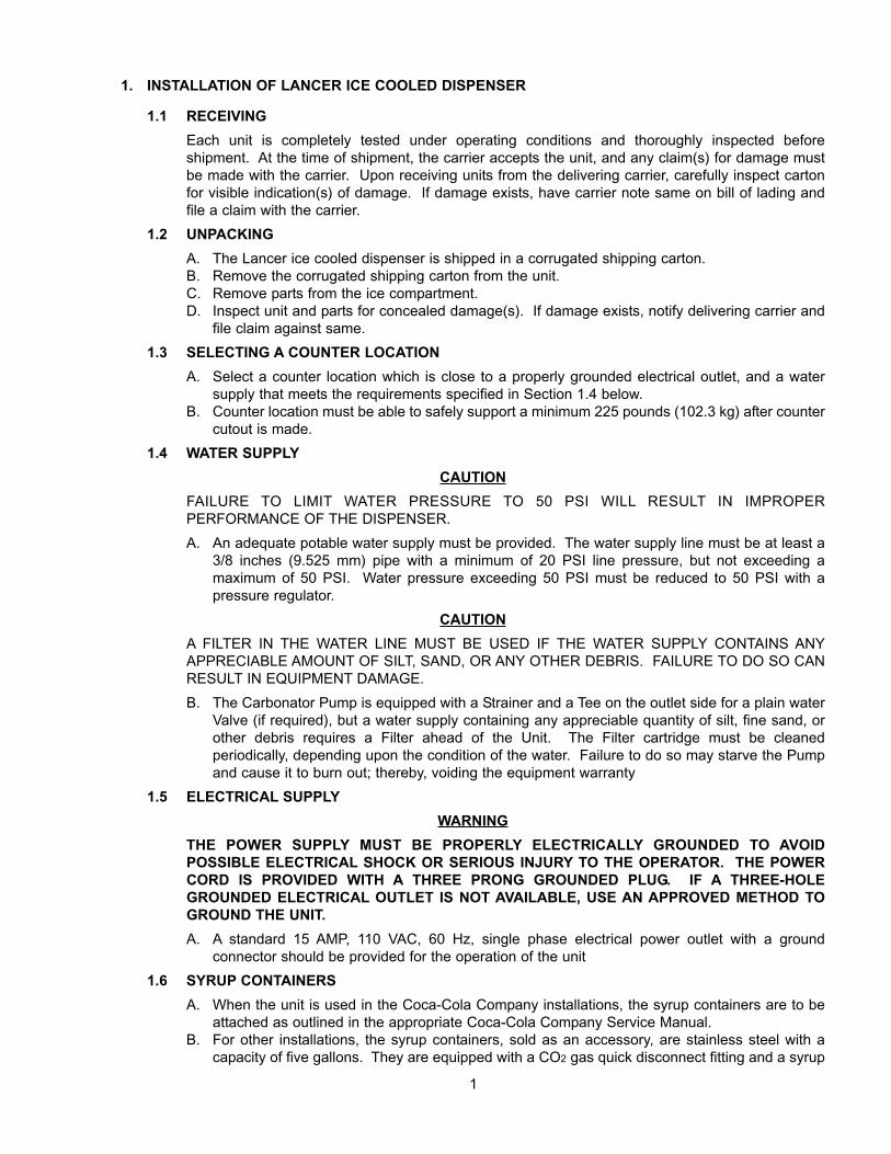
1.7 INSTALLATION OF THE UNITA Inspect the counter location where the unit is to be installed. Verify that the counter is strong
enough to safely support a 225 pounds (102.3 kg) load, after the cutout for the unit is made.B. Verify that the unit will fit in the desired location. See Figure 1 for the counter cutout for the unit.
NOTERemember that the unit can extend up to 23 inches (58.42 cm) below the counter, including theshipping risers, which Lancer recommends be left attached to the unit. Should the dispenserever require removal, the shipping risers will protect the inlet tubes from being damaged.
C. After the counter cutout is complete, the unit may be lowered into the counter.1.8 CONNECTION OF THE UNIT
A. Position the CO2 gas tank in location. Assemble high pressure regulator to CO2 gas tank andrun jumper line to low pressure regulator.
B. Attach the CO2 gas line to the carbonator by attaching the line from the high pressure regulatorto the single check valve marked "gas" on top of the carbonator tank. The setting of the highpressure CO2 gas regulator should be 90 PSI to 110 PSI.
CAUTIONDO NOT TURN ON THE CO2 AT THIS TIME.C. Position the syrup tanks in the desired location. Attach the CO2 gas lines leading from the low
pressure regulator to these tanks.D. Connect syrup lines from tanks to the appropriate inlets at the right front of the unit. The syrup
inlets are identified.CAUTION
A FILTER IN THE WATER LINE MUST BE USED IF THE WATER SUPPLY CONTAINS ANYAPPRECIABLE AMOUNT OF SILT, SAND, OR ANY OTHER DEBRIS. FAILURE TO DO SO CANRESULT IN EQUIPMENT DAMAGE.E. Mount the water filter assembly (if used) and water regulator in a convenient location.
CAUTIONFAILURE TO LIMIT WATER PRESSURE TO 50 PSI WILL RESULT IN IMPROPER PERFORMANCE OF THE DISPENSER.F. Connect water inlet line to water regulator, to water filter, and then to the water inlet of the
23 1/4"
23 1/4"
Counter Cutout for dispenserFigure 1
carbonator pump on the carbonator.G. Provide a suitable drain in the plumbing system and attach the one (1) inch (2.54 cm) diameter
schedule 40 PVC drains to it. The drip pan drainage outlet is located at the center rear of theunit. The ice water drainage outlet is located at the right front of the unit.
H. Be sure to place the ice trap in the drain outlet inside the ice bin before filling the cabinet withice. This device holds the ice away from the drain outlet, allowing the ice water to drain properly.
WARNINGTHE POWER SUPPLY MUST BE PROPERLY ELECTRICALLY GROUNDED TO AVOID POSSIBLE ELECTRICAL SHOCK OR SERIOUS INJURY TO THE OPERATOR. THE POWERCORD IS PROVIDED WITH A THREE PRONG GROUNDED PLUG. IF A THREE-HOLE GROUNDED ELECTRICAL OUTLET IS NOT AVAILABLE, USE AN APPROVED METHOD TOGROUND THE UNIT.I. Plug in the transformer box to a standard 15 AMP, 110 VAC, single phase outlet. The unit will
internally convert the 110 VAC to 24 VAC.1.9 START UP
A. After all connections to water, CO2 gas, electrical power, and syrup containers are made, checkfor leaks.
B. Be sure syrup tanks contain syrup.CAUTION
DO NOT OPERATE CARBONATOR PUMP WITH WATER SUPPLY SHUT OFF.C. Turn on water; open the pressure relief valve on the carbonator tank by lifting the wire ring or
flipping lever, and hold it open until water flows from the relief valve. Close the relief valve andturn on the CO2 gas and electrical power in that order.
D. To fill all lines with water, cycle the carbonator several times by operating the dispensing valves. 1. A low pressure gas regulator controls the flow of syrup to each dispensing valve. For
proper operation of the valves, the pressure regulator should be set so that 40 PSI is at thebackblock of the valve.
2. For diet type syrup, the tank pressures should be set at 10 PSI (or as recommended by the
3
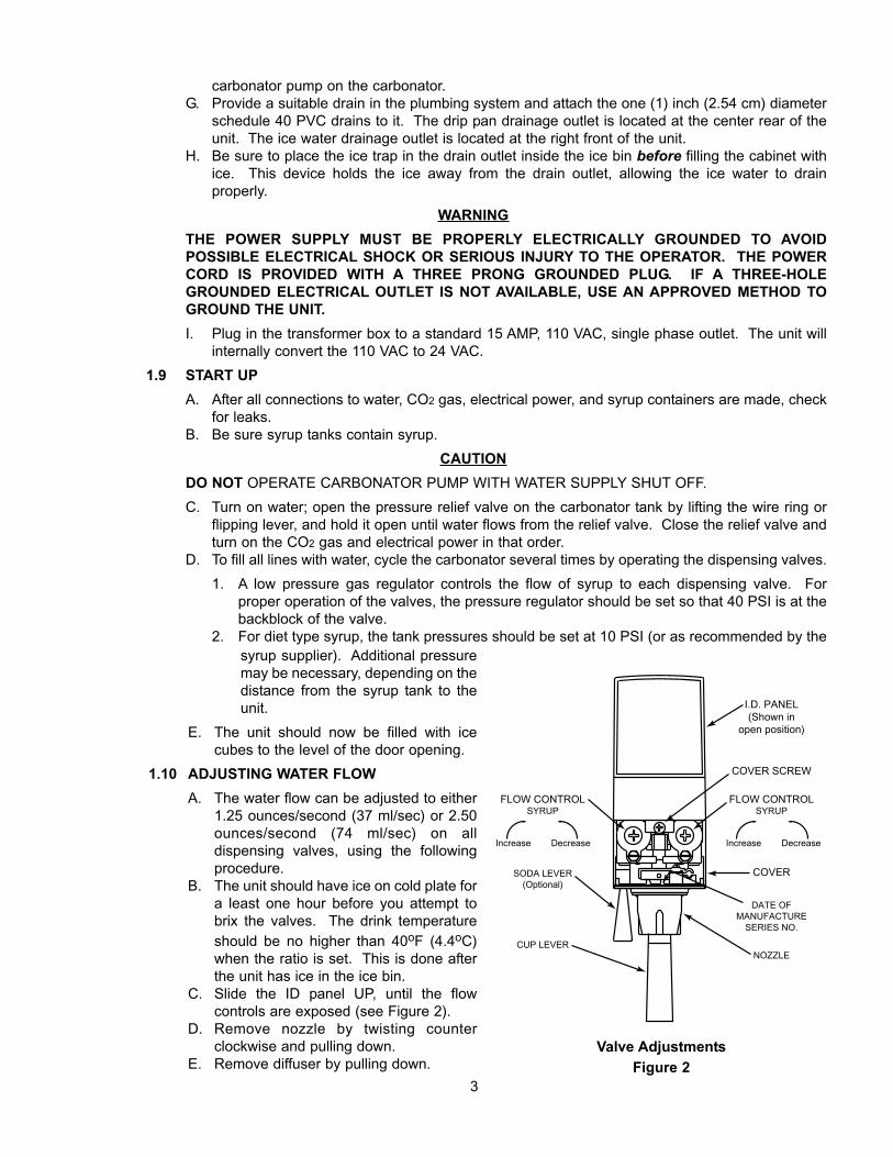
I.D. PANEL�(Shown in�
open position)
COVER SCREW
FLOW CONTROL�SYRUP
DecreaseIncrease
COVER
DATE OF�MANUFACTURE�
SERIES NO.
NOZZLE
SODA LEVER�(Optional)
CUP LEVER��
FLOW CONTROL�SYRUP
DecreaseIncrease
Valve AdjustmentsFigure 2
syrup supplier). Additional pressuremay be necessary, depending on thedistance from the syrup tank to theunit.
E. The unit should now be filled with icecubes to the level of the door opening.
1.10 ADJUSTING WATER FLOWA. The water flow can be adjusted to either
1.25 ounces/second (37 ml/sec) or 2.50ounces/second (74 ml/sec) on all dispensing valves, using the followingprocedure.
B. The unit should have ice on cold plate fora least one hour before you attempt tobrix the valves. The drink temperatureshould be no higher than 40oF (4.4oC)when the ratio is set. This is done afterthe unit has ice in the ice bin.
C. Slide the ID panel UP, until the flow controls are exposed (see Figure 2).
D. Remove nozzle by twisting counterclockwise and pulling down.
E. Remove diffuser by pulling down.
F. Install Lancer (yellow) syrup separator (PN 54-0031) in place of nozzle.G. Activate dispensing valve to fill separator syrup tube.H. Hold a Lancer brix cup under the syrup separator and dispense water and syrup into cup for
four (4) seconds. Divide number of ounces (ml) of water in cup by four (4) to determine waterflow rate per second.
I. To obtain the proper flow, use a screwdriver to adjust water flow control (see Figure 2).J. Repeat process for each valve.
1.11 ADJUSTING WATER TO SYRUP RATIO (BRIX)A. Hold the Lancer brix cup under the syrup separator and activate valve. Check ratio (brix).B. To obtain the proper ratio, use screwdriver to adjust syrup flow control (see Figure 2).C. Remove syrup separator.D. Install diffuser and nozzle.E. Slide ID panel DOWN.F. Repeat process for each valve.
NOTEIn all cases of reassembly of valves involving o-rings, be sure the o-ring is lubricated with anFDA approved lubricant or water to prevent leakage or damage to the o-ring.
1.12 REPLENISHING SYRUP SUPPLY (5 GALLON TANKS)A. To add syrup to a tank after the system is in operation, the following procedure should be used.
1. Shut off CO2 gas supply system to syrup tanks.2. Snap off the self-sealing quick-coupler and allow gas in syrup tank to escape by pulling the
outer shell of the quick-coupler toward the flexible line and allowing the whole connection topull free.
WARNINGTO AVOID POSSIBLE PERSONAL INJURY OR PROPERTY DAMAGE, DO NOT ATTEMPTTO REMOVE SYRUP TANK COVER UNTIL CO2 PRESSURE HAS BEEN RELEASED FROMTANK.3. Remove the cover by pulling upward on the hinged locking bar.4. Fill tank with appropriate syrup, leaving one (1) inch (2.54 cm) of space for CO2 gas.5. Replace locking cover insuring that the cover and cover gasket are properly aligned.6. Snap on quick-coupler and lock it securely in place. Turn CO2 gas pressure ON. When
properly connected, the gas will automatically enter the tank with an audible noise.
2. RECOMMENDED SERVICE AND MAINTENANCE
2.1 SCHEDULEDA. Daily – See Section 2.5 for daily cleaning.B Monthly – See Section 2.6 for monthly cleaning.C. Periodic Sanitizing - See sections 2.2, 2.3, and 2.4 for sanitizing requirements.D. As Needed - Keep exterior surfaces (to include drip tray and cup rest) of dispenser cleaned with
damp, clean cloth.2.2 CLEANING AND SANITIZING SYSTEMS
A. General Information(1) Lancer equipment (new or reconditioned) is shipped from the factory cleaned and sanitized
in accordance with NSF guidelines. The operator of the equipment must provide continuous maintenance as required by this manual and/or state and local health department guidelines to ensure proper operation and sanitation requirements are maintained.
NOTEThe cleaning and sanitizing procedures provided herein pertain to the Lancer equipmentidentified by this manual. If other equipment is being cleaned, follow the guidelines established for that equipment.
4
(2) Cleaning and sanitizing should be accomplished only by trained personnel. Sanitary glovesare to be used during cleaning and sanitizing operations. Applicable safety precautionsmust be observed. Instruction warnings on the product being used must be followed.
IMPORTANTWater lines are not to be disconnected during the cleaning and sanitizing of syrup lines toavoid contamination.
(3) Recommended Preparation of Cleaning Solutions.(a) Cleaning solutions (for example, Ivory Liquid, Calgon, etc.) mixed with clean, potable
water at a temperature of 90 to 110 degrees Fahrenheit should be used to clean equipment. The mixture ratio, using Ivory Liquid, is one (1) ounce of cleanser to two (2)gallons of water. A minimum of four (4) gallons of cleaning mixture should be prepared.
NOTEExtended lengths of product lines may require that an additional volume of solution beprepared.
(b) Any equivalent cleanser may be used as long as it provides a caustic based, non-perfumed, easily rinsed mixture containing at least two (2) percent sodium hydroxide (NaOH).
(4) Recommended Preparation of Sanitizing Solutions.(a) Sanitizing solutions should be prepared in accordance with the manufacturer’s written
recommendations and safety guidelines. Follow manufacturer’s requirements so thatthe solution provides 200 parts per million (PPM) available chlorine at a temperature of90oF to 120oF. A minimum of four (4) gallons of sanitizing solution should be prepared.
NOTEExtended lengths of product lines may require that an additional volume of solution beprepared.
(b) Any sanitizing solution may be used as long as it is prepared in accordance with themanufacturer’s written recommendations and safety guidelines, and provides 200 partsper million (PPM) available chlorine.
2.3 CLEANING AND SANITIZING FIGAL SYSTEMSA. Remove all ice from ice bin by melting with hot water.B. Remove quick disconnect from syrup tank.
CAUTIONDO NOT USE A WIRE BRUSH TO CLEAN VALVES.C. Using a clean plastic bristle brush and a detergent soap solution prepared in accordance with
the instructions in Section 2.2, scrub both valves of the disconnect. Rinse with clean, potablewater.
D. Using a mechanical spray bottle and a sanitizing solution prepared in accordance with theinstructions in Section 2.2, spray both halves of the quick disconnects. Allow to air dry.
NOTEPlease note that a fresh water rinse cannot follow sanitization of equipment. Purge only with theend use product. This is an NSF requirement.
E. Connect syrup line to a syrup tank filled with clean, potable, room temperature water. ConnectCO2 supply hose to tank and pressurize.
F. Place waste container under applicable dispensing valve. Activate valve until water is dispensed. Flush and rinse line and fittings for a minimum of 60 seconds to remove all tracesof residual product.
NOTEExtended lengths of product lines may require additional time for flushing and rinsing lines.
5
WARNINGTO AVOID POSSIBLE PERSONAL INJURY OR PROPERTY DAMAGE, DO NOT ATTEMPTTO REMOVE SYRUP TANK COVER UNTIL CO2 PRESSURE HAS BEEN RELEASED FROMTANK.
G. Disconnect CO2 supply hose from the water filled syrup tank.H. Prepare cleaning solution as described in Section 2.2 above. Fill a tank with cleaning solution.
Connect syrup line to the tank. Connect CO2 supply hose to tank and pressurize.I. Place waste container under applicable dispensing valve. Activate valve and draw cleaning
solution through lines for a minimum of 60 seconds. This will ensure line is flushed and filledwith cleaning solution. Allow line to stand for at least 30 minutes.
NOTEExtended lengths of product lines may require additional time for flushing and filling lines.
J. Disconnect CO2 supply hose from the tank.K. Connect syrup line to a tank filled with clean, potable, water at a temperature of 90 to 110oF.
Connect CO2 supply hose to tank and pressurize.L. Place waste container under applicable dispensing valve. Activate valve to flush and rinse line
and fittings for a minimum of 60 seconds to remove all traces of cleaning solution. Continue rinsing until testing with phenolpthalein shows that the rinse water is free of residual detergent.
M. Disconnect CO2 supply hose from the tank.N. Fill a tank with sanitizing solution. Connect syrup line to the tank. Connect CO2 supply hose to
tank and pressurize.O. Remove dispensing valve nozzle (twist and pull down) and pull out center mixing baffle. Using
a plastic bristle brush and detergent soap solution scrub the nozzle, mixing baffle, bottom of dispensing valve, and cup lever. Rinse with clean water.
P. Reassemble mixing baffle and nozzle.Q. Place waste container under applicable dispensing valve. Activate valve and draw sanitizing
solution through line for a minimum of 60 seconds. This will ensure line is flushed and filled withsanitizing solution. Allow line to stand for at least 30 minutes.
R. Disconnect CO2 supply hose from the tank.S. Reconnect syrup lines to syrup containers (for example, quick disconnects, figal containers, etc.)
and ready unit for operation.WARNING
FLUSH SANITIZING SOLUTION FROM SYRUP SYSTEMS AS INSTRUCTED. RESIDUALSANITIZING SOLUTION LEFT IN SYSTEM COULD CREATE A HEALTH HAZARD.T. Draw drinks and refill lines with end product to flush sanitizing solution from the dispenser.
NOTEPlease note that a fresh water rinse cannot follow sanitization of equipment. Purge only with theend use product. This is an NSF requirement.
U. Test dispenser in normal manner for proper operation. Taste dispensed product to ensure thereis no off-taste. If off-taste is found, additional flushing of syrup system may be required.
V. Repeat cleaning, rinsing, and sanitizing procedures for each valve/syrup circuit.W. Clean exterior of unit as instructed in Section 2.6.X. Using a spray bottle of sanitizing solution, spray the underside of all dispenser valves, valve
spouts and cup levers. Allow to air dry.NOTE
Thoroughly rinse inside and outside of syrup tank that was used for sanitizing solution with plainwater to remove all solution residue.
Y. Fill ice bin with ice. Install ice bin cover on unit.2.4 CLEANING AND SANITIZING BAG-IN-BOX (BIB) SYSTEMS
A. Disconnect syrup quick disconnect coupling from syrup packages and connect coupling to a bag
6
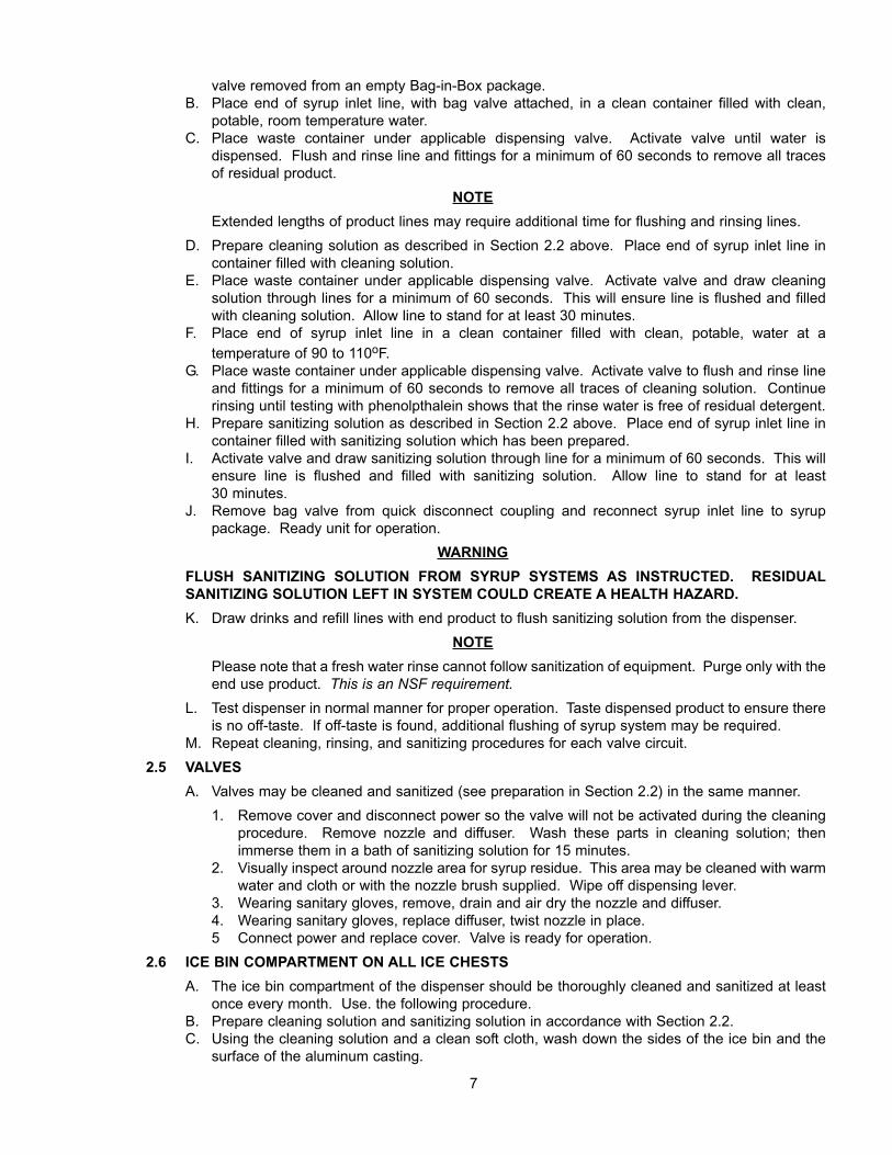
valve removed from an empty Bag-in-Box package.B. Place end of syrup inlet line, with bag valve attached, in a clean container filled with clean,
potable, room temperature water.C. Place waste container under applicable dispensing valve. Activate valve until water is
dispensed. Flush and rinse line and fittings for a minimum of 60 seconds to remove all tracesof residual product.
NOTEExtended lengths of product lines may require additional time for flushing and rinsing lines.
D. Prepare cleaning solution as described in Section 2.2 above. Place end of syrup inlet line incontainer filled with cleaning solution.
E. Place waste container under applicable dispensing valve. Activate valve and draw cleaning solution through lines for a minimum of 60 seconds. This will ensure line is flushed and filledwith cleaning solution. Allow line to stand for at least 30 minutes.
F. Place end of syrup inlet line in a clean container filled with clean, potable, water at a temperature of 90 to 110oF.
G. Place waste container under applicable dispensing valve. Activate valve to flush and rinse lineand fittings for a minimum of 60 seconds to remove all traces of cleaning solution. Continue rinsing until testing with phenolpthalein shows that the rinse water is free of residual detergent.
H. Prepare sanitizing solution as described in Section 2.2 above. Place end of syrup inlet line incontainer filled with sanitizing solution which has been prepared.
I. Activate valve and draw sanitizing solution through line for a minimum of 60 seconds. This willensure line is flushed and filled with sanitizing solution. Allow line to stand for at least 30 minutes.
J. Remove bag valve from quick disconnect coupling and reconnect syrup inlet line to syrup package. Ready unit for operation.
WARNINGFLUSH SANITIZING SOLUTION FROM SYRUP SYSTEMS AS INSTRUCTED. RESIDUALSANITIZING SOLUTION LEFT IN SYSTEM COULD CREATE A HEALTH HAZARD.K. Draw drinks and refill lines with end product to flush sanitizing solution from the dispenser.
NOTEPlease note that a fresh water rinse cannot follow sanitization of equipment. Purge only with theend use product. This is an NSF requirement.
L. Test dispenser in normal manner for proper operation. Taste dispensed product to ensure thereis no off-taste. If off-taste is found, additional flushing of syrup system may be required.
M. Repeat cleaning, rinsing, and sanitizing procedures for each valve circuit.2.5 VALVES
A. Valves may be cleaned and sanitized (see preparation in Section 2.2) in the same manner.1. Remove cover and disconnect power so the valve will not be activated during the cleaning
procedure. Remove nozzle and diffuser. Wash these parts in cleaning solution; thenimmerse them in a bath of sanitizing solution for 15 minutes.
2. Visually inspect around nozzle area for syrup residue. This area may be cleaned with warmwater and cloth or with the nozzle brush supplied. Wipe off dispensing lever.
3. Wearing sanitary gloves, remove, drain and air dry the nozzle and diffuser.4. Wearing sanitary gloves, replace diffuser, twist nozzle in place.5 Connect power and replace cover. Valve is ready for operation.
2.6 ICE BIN COMPARTMENT ON ALL ICE CHESTSA. The ice bin compartment of the dispenser should be thoroughly cleaned and sanitized at least
once every month. Use. the following procedure.B. Prepare cleaning solution and sanitizing solution in accordance with Section 2.2.C. Using the cleaning solution and a clean soft cloth, wash down the sides of the ice bin and the
surface of the aluminum casting.
7
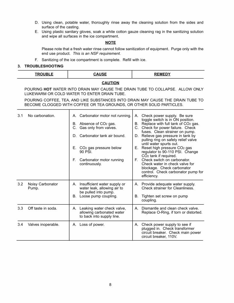
D. Using clean, potable water, thoroughly rinse away the cleaning solution from the sides and surface of the casting.
E. Using plastic sanitary gloves, soak a white cotton gauze cleaning rag in the sanitizing solutionand wipe all surfaces in the ice compartment.
NOTEPlease note that a fresh water rinse cannot follow sanitization of equipment. Purge only with theend use product. This is an NSF requirement.
F. Sanitizing of the ice compartment is complete. Refill with ice.3. TROUBLESHOOTING
TROUBLE CAUSE REMEDY
CAUTIONPOURING HOT WATER INTO DRAIN MAY CAUSE THE DRAIN TUBE TO COLLAPSE. ALLOW ONLYLUKEWARM OR COLD WATER TO ENTER DRAIN TUBE.POURING COFFEE, TEA, AND LIKE SUBSTANCES INTO DRAIN MAY CAUSE THE DRAIN TUBE TOBECOME CLOGGED WITH COFFEE OR TEA GROUNDS, OR OTHER SOLID PARTICLES.
3.1 No carbonation. A. Carbonator motor not running. A. Check power supply. Be suretoggle switch is in ON position.
B. Absence of CO2 gas. B. Replace with full tank of CO2 gas.C. Gas only from valves. C. Check for power failure. Check
fuses. Clean strainer on pump.D. Carbonator tank air bound. D. Relieve gas pressure in tank by
pulling ring on safety relief valveuntil water spurts out.
E. CO2 gas pressure below E. Reset high pressure CO2 gas90 PSI. regulator to 90-110 PSI. Change
CO2 tank if required.F. Carbonator motor running F. Check switch on carbonator.
continuously. Check water in check valve for blockage. Check carbonator control. Check carbonator pump forefficiency.
3.2 Noisy Carbonator A. Insufficient water supply or A. Provide adequate water supply.Pump. water leak, allowing air to Check strainer for Cleanliness.
be pulled into pump.B. Loose pump coupling. B. Tighten set screw on pump
coupling.
3.3 Off taste in soda. A. Leaking water check valve, A. Dismantle and clean check valve.allowing carbonated water Replace O-Ring, if torn or distorted.to back into supply line.
3.4 Valves inoperable. A. Loss of power. A. Check power supply to see ifplugged in. Check transformercircuit breaker. Check main powercircuit breaker, 110V.
8

9
NOTES
COVER MUST BE COMPLETELY
CLOSED TO OPERATE VALVES
SLIDING COVER
DO NOT LIFT
35
34
33
32
31
30
23
22
21
20
19
18
17
16
15
1413128
6
11109
5
4
3
1
2
29 2827
2425
26
7
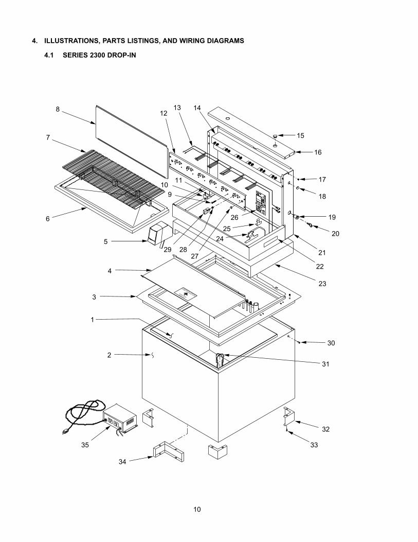
4. ILLUSTRATIONS, PARTS LISTINGS, AND WIRING DIAGRAMS
4.1 SERIES 2300 DROP-IN
10
11
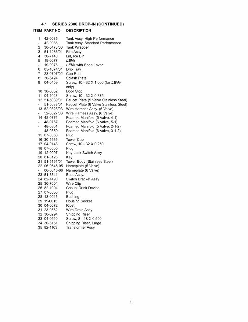
4.1 SERIES 2300 DROP-IN (CONTINUED)ITEM PART NO. DESCRIPTION
1 42-0035 Tank Assy, High Performance- 42-0036 Tank Assy, Standard Performance2 30-5473/03 Tank Wrapper3 51-1236/01 Rim Assy4 30-7140 Lid, Ice Bin5 19-0077 LEV®- 19-0078 LEV® with Soda Lever6 05-1074/01 Drip Tray7 23-0797/02 Cup Rest8 30-5424 Splash Plate9 04-0459 Screw, 10 - 32 X 1.000 (for LEV®
only)10 30-6052 Door Stop11 04-1028 Screw, 10 - 32 X 0.37512 51-5089/01 Faucet Plate (5 Valve Stainless Steel)- 51-5088/01 Faucet Plate (6 Valve Stainless Steel)13 52-0828/03 Wire Harness Assy. (5 Valve)- 52-0827/03 Wire Harness Assy. (6 Valve)14 48-0776 Foamed Manifold (5 Valve, 4-1)- 48-0767 Foamed Manifold (6 Valve, 5-1)- 48-0851 Foamed Manifold (5 Valve, 2-1-2)- 48-0850 Foamed Manifold (6 Valve, 3-1-2)15 07-0360 Plug16 30-5986 Tower Cap17 04-0148 Screw, 10 - 32 X 0.25018 07-0555 Plug19 12-0097 Key Lock Switch Assy20 81-0126 Key21 51-5161/01 Tower Body (Stainless Steel)22 06-0645-05 Nameplate (5 Valve)- 06-0645-06 Nameplate (6 Valve)23 51-5541 Base Assy.24 82-1490 Switch Bracket Assy25 30-7004 Wire Clip26 82-1094 Casual Drink Device27 07-0556 Plug28 13-0015 Bushing29 11-0015 Housing Socket30 04-0072 Rivet31 23-0862 Wire Drain Assy32 30-0294 Shipping Riser33 04-0510 Screw, 8 - 18 X 0.50034 30-5151 Shipping Riser, Large35 82-1103 Transformer Assy
CLOSED TO OPERATE VALVES
COVER MUST BE COMPLETELY
SLIDING COVER
DO NOT LIFT
32
33
30
22
21
20
19
18
17
31
34
3536
16
15
14
811 12
13
7
6
5
4
3
1
2
910
29
28 27
2625 24
23
12
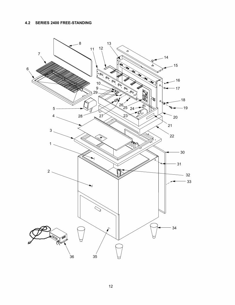
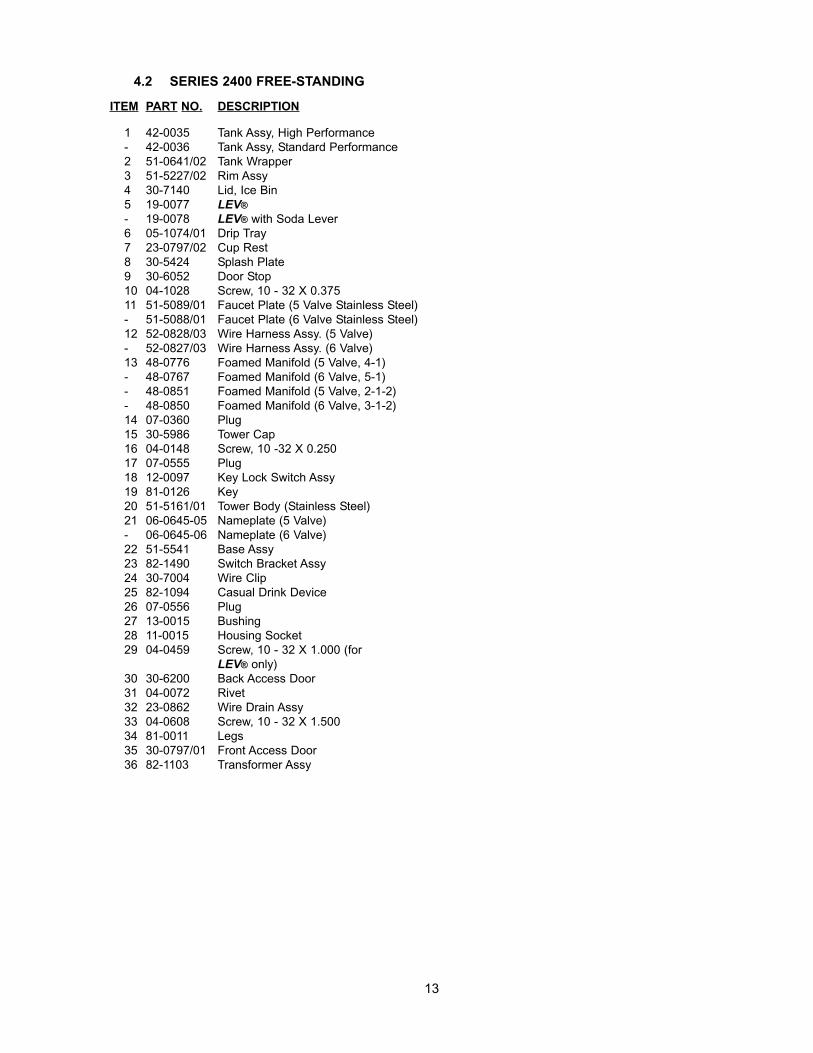
4.2 SERIES 2400 FREE-STANDING
ITEM PART NO. DESCRIPTION
1 42-0035 Tank Assy, High Performance- 42-0036 Tank Assy, Standard Performance2 51-0641/02 Tank Wrapper3 51-5227/02 Rim Assy4 30-7140 Lid, Ice Bin5 19-0077 LEV®- 19-0078 LEV® with Soda Lever6 05-1074/01 Drip Tray7 23-0797/02 Cup Rest8 30-5424 Splash Plate9 30-6052 Door Stop10 04-1028 Screw, 10 - 32 X 0.37511 51-5089/01 Faucet Plate (5 Valve Stainless Steel)- 51-5088/01 Faucet Plate (6 Valve Stainless Steel)12 52-0828/03 Wire Harness Assy. (5 Valve)- 52-0827/03 Wire Harness Assy. (6 Valve)13 48-0776 Foamed Manifold (5 Valve, 4-1)- 48-0767 Foamed Manifold (6 Valve, 5-1)- 48-0851 Foamed Manifold (5 Valve, 2-1-2)- 48-0850 Foamed Manifold (6 Valve, 3-1-2)14 07-0360 Plug15 30-5986 Tower Cap16 04-0148 Screw, 10 -32 X 0.25017 07-0555 Plug18 12-0097 Key Lock Switch Assy19 81-0126 Key20 51-5161/01 Tower Body (Stainless Steel)21 06-0645-05 Nameplate (5 Valve)- 06-0645-06 Nameplate (6 Valve)22 51-5541 Base Assy23 82-1490 Switch Bracket Assy24 30-7004 Wire Clip25 82-1094 Casual Drink Device26 07-0556 Plug27 13-0015 Bushing28 11-0015 Housing Socket29 04-0459 Screw, 10 - 32 X 1.000 (for
LEV® only)30 30-6200 Back Access Door31 04-0072 Rivet32 23-0862 Wire Drain Assy33 04-0608 Screw, 10 - 32 X 1.50034 81-0011 Legs35 30-0797/01 Front Access Door36 82-1103 Transformer Assy
13
4.2 SERIES 2400 FREE-STANDING
CLOSED TO OPERATE VALVES
COVER MUST BE COMPLETELYDO NOT LIFT
SLIDING COVER
30
22
21
20
19
18
17
31
33
3435
16
13 14
32
29
15
121110
9
8
7
2
1
3
45
6
2728
2625
24
23
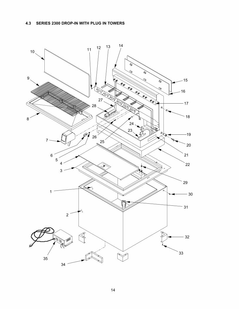
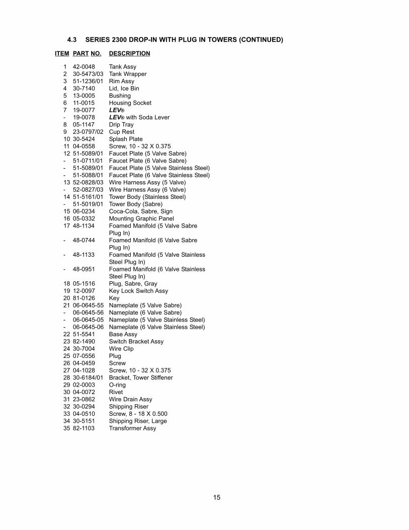
4.3 SERIES 2300 DROP-IN WITH PLUG IN TOWERS
14
ITEM PART NO. DESCRIPTION
1 42-0048 Tank Assy2 30-5473/03 Tank Wrapper3 51-1236/01 Rim Assy4 30-7140 Lid, Ice Bin5 13-0005 Bushing6 11-0015 Housing Socket7 19-0077 LEV®- 19-0078 LEV® with Soda Lever8 05-1147 Drip Tray9 23-0797/02 Cup Rest10 30-5424 Splash Plate11 04-0558 Screw, 10 - 32 X 0.37512 51-5089/01 Faucet Plate (5 Valve Sabre)- 51-0711/01 Faucet Plate (6 Valve Sabre)- 51-5089/01 Faucet Plate (5 Valve Stainless Steel)- 51-5088/01 Faucet Plate (6 Valve Stainless Steel)13 52-0828/03 Wire Harness Assy (5 Valve)- 52-0827/03 Wire Harness Assy (6 Valve)14 51-5161/01 Tower Body (Stainless Steel)- 51-5019/01 Tower Body (Sabre)15 06-0234 Coca-Cola, Sabre, Sign16 05-0332 Mounting Graphic Panel17 48-1134 Foamed Manifold (5 Valve Sabre
Plug In)- 48-0744 Foamed Manifold (6 Valve Sabre
Plug In)- 48-1133 Foamed Manifold (5 Valve Stainless
Steel Plug In)- 48-0951 Foamed Manifold (6 Valve Stainless
Steel Plug In)18 05-1516 Plug, Sabre, Gray19 12-0097 Key Lock Switch Assy20 81-0126 Key21 06-0645-55 Nameplate (5 Valve Sabre)- 06-0645-56 Nameplate (6 Valve Sabre)- 06-0645-05 Nameplate (5 Valve Stainless Steel)- 06-0645-06 Nameplate (6 Valve Stainless Steel)22 51-5541 Base Assy23 82-1490 Switch Bracket Assy24 30-7004 Wire Clip25 07-0556 Plug26 04-0459 Screw27 04-1028 Screw, 10 - 32 X 0.37528 30-6184/01 Bracket, Tower Stiffener29 02-0003 O-ring30 04-0072 Rivet31 23-0862 Wire Drain Assy32 30-0294 Shipping Riser33 04-0510 Screw, 8 - 18 X 0.50034 30-5151 Shipping Riser, Large35 82-1103 Transformer Assy
4.3 SERIES 2300 DROP-IN WITH PLUG IN TOWERS (CONTINUED)
15
32
33
30
22
21 20
19
18
17
31
34
35
36
16
29
15
13 141211
10
9
8
7
45
6
2728
2625
24
23
3
1
2
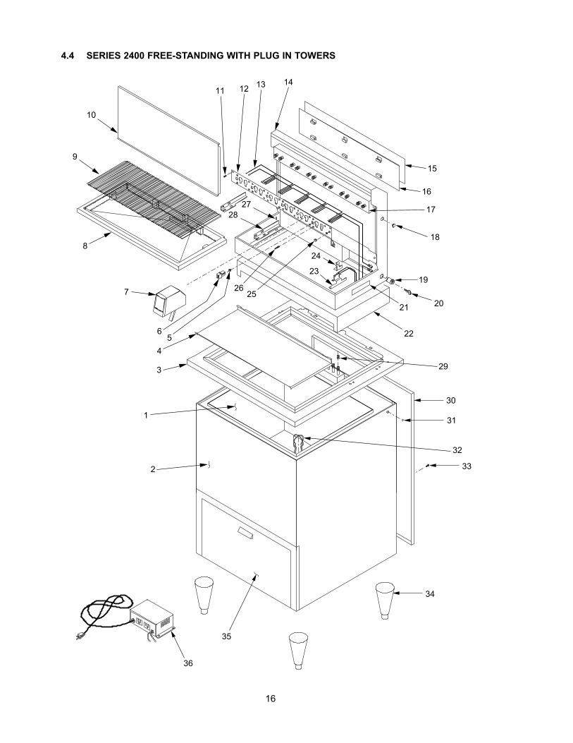
4.4 SERIES 2400 FREE-STANDING WITH PLUG IN TOWERS
16
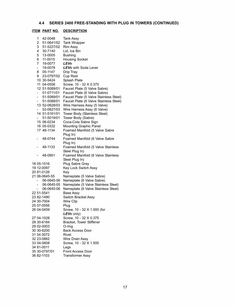
ITEM PART NO. DESCRIPTION
1 42-0048 Tank Assy2 51-0641/02 Tank Wrapper3 51-5227/02 Rim Assy4 30-7140 Lid, Ice Bin5 13-0005 Bushing6 11-0015 Housing Socket7 19-0077 LEV®- 19-0078 LEV® with Soda Lever8 05-1147 Drip Tray9 23-0797/02 Cup Rest10 30-5424 Splash Plate11 04-0558 Screw, 10 - 32 X 0.37512 51-5089/01 Faucet Plate (5 Valve Sabre)- 51-0711/01 Faucet Plate (6 Valve Sabre)- 51-5089/01 Faucet Plate (5 Valve Stainless Steel)- 51-5088/01 Faucet Plate (6 Valve Stainless Steel)13 52-0828/03 Wire Harness Assy (5 Valve)- 52-0827/03 Wire Harness Assy (6 Valve)14 51-5161/01 Tower Body (Stainless Steel)- 51-5019/01 Tower Body (Sabre)15 06-0234 Coca-Cola Sabre Sign16 05-0332 Mounting Graphic Panel17 48-1134 Foamed Manifold (5 Valve Sabre
Plug In)- 48-0744 Foamed Manifold (6 Valve Sabre
Plug In)- 48-1133 Foamed Manifold (5 Valve Stainless
Steel Plug In)- 48-0951 Foamed Manifold (6 Valve Stainless
Steel Plug In)18 05-1516 Plug Sabre Gray19 12-0097 Key Lock Switch Assy20 81-0126 Key21 06-0645-55 Nameplate (5 Valve Sabre)
- 06-0645-56 Nameplate (6 Valve Sabre)- 06-0645-05 Nameplate (5 Valve Stainless Steel)- 06-0645-06 Nameplate (6 Valve Stainless Steel)
22 51-5541 Base Assy23 82-1490 Switch Bracket Assy24 30-7004 Wire Clip25 07-0556 Plug26 04-0459 Screw, 10 - 32 X 1.000 (for
LEV® only)27 04-1028 Screw, 10 - 32 X 0.37528 30-6184 Bracket, Tower Stiffener29 02-0003 O-ring30 30-6200 Back Access Door31 04 0072 Rivet32 23-0862 Wire Drain Assy33 04-0608 Screw, 10 - 32 X 1.50034 81-0011 Legs35 30-0797/01 Front Access Door36 82-1103 Transformer Assy
4.4 SERIES 2400 FREE-STANDING WITH PLUG IN TOWERS (CONTINUED)
17
28
27
23
20
26
18
17
25
16
11
15
10
7
6
5
3
2
1
24
22
14
12
13
19
21
8
9
4
18
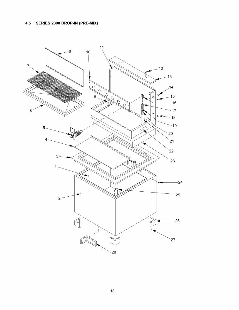
4.5 SERIES 2300 DROP-IN (PRE-MIX)
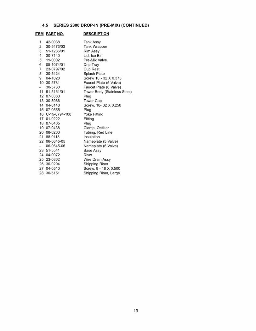
ITEM PART NO. DESCRIPTION
1 42-0038 Tank Assy2 30-5473/03 Tank Wrapper3 51-1236/01 Rim Assy4 30-7140 Lid, Ice Bin5 19-0002 Pre-Mix Valve6 05-1074/01 Drip Tray7 23-0797/02 Cup Rest8 30-5424 Splash Plate9 04-1028 Screw 10 - 32 X 0.37510 30-5731 Faucet Plate (5 Valve)- 30-5730 Faucet Plate (6 Valve)11 51-5161/01 Tower Body (Stainless Steel)12 07-0360 Plug13 30-5986 Tower Cap14 04-0148 Screw, 10- 32 X 0.25015 07-0555 Plug16 C-15-0794-100 Yoke Fitting17 01-0222 Fitting18 07-0405 Plug19 07-0438 Clamp, Oetiker20 08-0263 Tubing, Red Line21 88-0118 Insulation22 06-0645-05 Nameplate (5 Valve)- 06-0645-06 Nameplate (6 Valve)23 51-5541 Base Assy24 04-0072 Rivet25 23-0862 Wire Drain Assy26 30-0294 Shipping Riser27 04-0510 Screw, 8 - 18 X 0.50028 30-5151 Shipping Riser, Large
19
4.5 SERIES 2300 DROP-IN (PRE-MIX) (CONTINUED)
28
27
23
20
26
1817
16
11
15
10
7
6
5
3
2
1
25
22
14
12
13
19
21
8
9
4
29
24
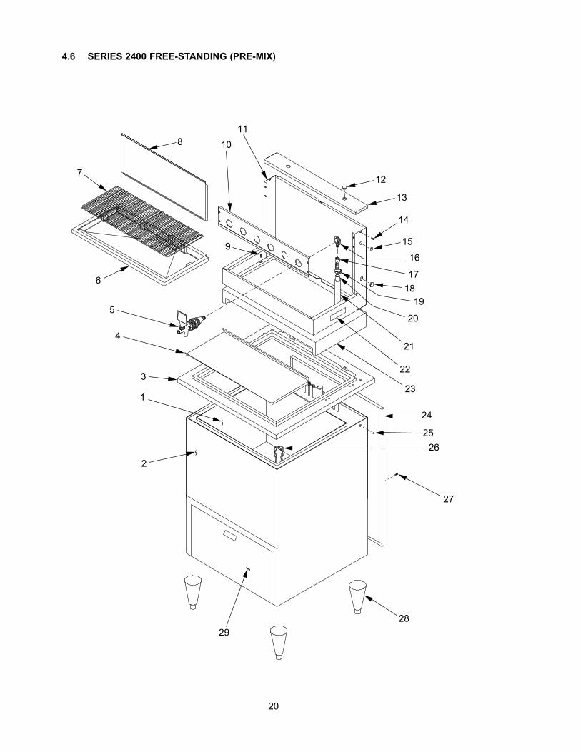
4.6 SERIES 2400 FREE-STANDING (PRE-MIX)
20
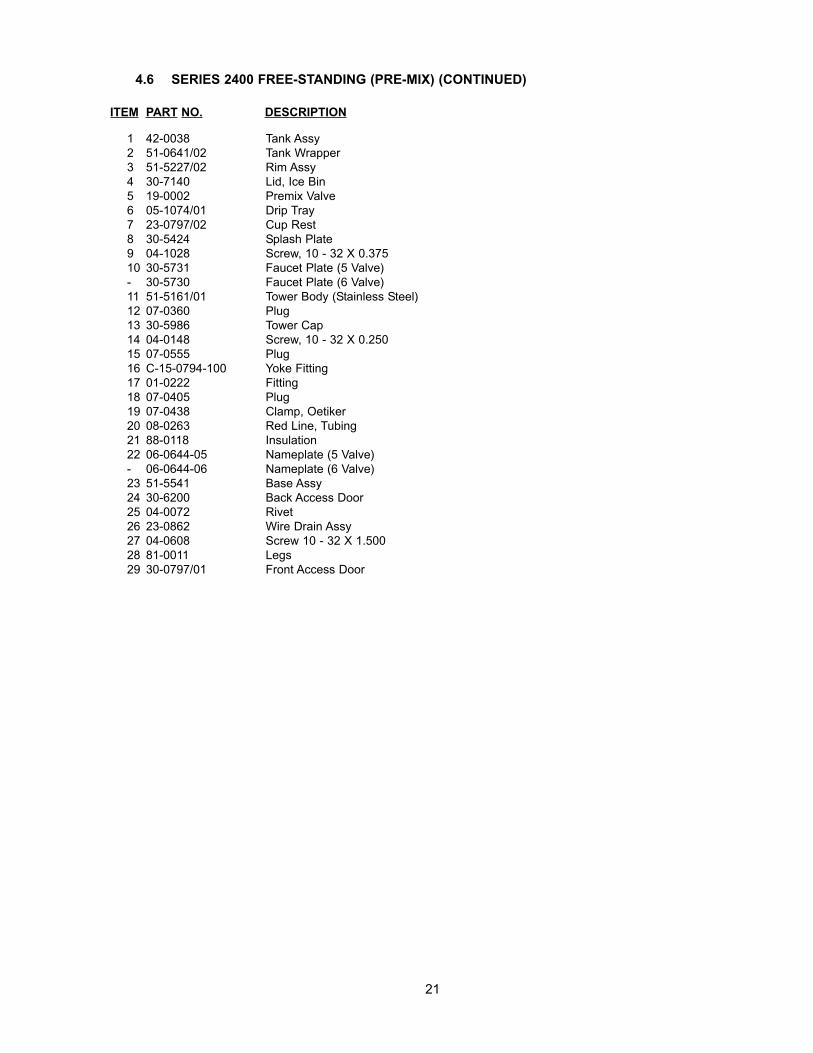
ITEM PART NO. DESCRIPTION
1 42-0038 Tank Assy2 51-0641/02 Tank Wrapper3 51-5227/02 Rim Assy4 30-7140 Lid, Ice Bin5 19-0002 Premix Valve6 05-1074/01 Drip Tray7 23-0797/02 Cup Rest8 30-5424 Splash Plate9 04-1028 Screw, 10 - 32 X 0.37510 30-5731 Faucet Plate (5 Valve)- 30-5730 Faucet Plate (6 Valve)11 51-5161/01 Tower Body (Stainless Steel)12 07-0360 Plug13 30-5986 Tower Cap14 04-0148 Screw, 10 - 32 X 0.25015 07-0555 Plug16 C-15-0794-100 Yoke Fitting17 01-0222 Fitting18 07-0405 Plug19 07-0438 Clamp, Oetiker20 08-0263 Red Line, Tubing21 88-0118 Insulation22 06-0644-05 Nameplate (5 Valve)- 06-0644-06 Nameplate (6 Valve)23 51-5541 Base Assy24 30-6200 Back Access Door25 04-0072 Rivet26 23-0862 Wire Drain Assy27 04-0608 Screw 10 - 32 X 1.50028 81-0011 Legs29 30-0797/01 Front Access Door
4.6 SERIES 2400 FREE-STANDING (PRE-MIX) (CONTINUED)
21
2MBLAC
K
F
: "Y"
CO
NN
ECTO
R (2
MAL
ES, 1
FEM
ALE)
: 2 P
IN F
EMAL
E C
ON
NEC
TOR
: 2 P
IN M
ALE
CO
NN
ECTO
R
: 3 P
IN M
ALE
CO
NN
ECTO
R: 3
PIN
FEM
ALE
CO
NN
ECTO
R
: MAL
E BL
ADE
3F Y3MM 2F 2M
ALTE
RN
ATE�
POW
ER S
UPP
LY
: FEM
ALE
BLAD
E R
ECEP
TAC
LE
2F
MAR
QU
EE�
OR
�M
ERC
HAN
DIS
ER2M
BIN
�SW
ITC
H
F
F
F
THIS
HA
RN
ESS
IS N
OT
USE
D�
IN C
ON
JUN
CTI
ON
WIT
H�
ALT
ERN
ATE
PO
WER
SU
PPLY
2F2F2M
2F 2M
FM
WH
ITE
M
WH
ITE
F
Y
WH
ITE
FMW
HIT
E
FBL
ACK
BLAC
KF
2M 2FW
HIT
E
WH
ITE
FF
WAT
ER S
PIG
OT�
BUTT
ON
2F
REP
LAC
ES IN
TER
NAL
�C
HER
RY
SWIT
CH
HAR
NES
S�O
N S
PRIT
E VA
LVE
F
F
2F
VALV
E M
ANIF
OLD
HAR
NES
S
2F2F
2M
BLAC
K
WH
ITE
2F
SYR
UP
OU
T�LI
GH
T KI
T
3M3F
2F O
RIG
INAL
�PO
WER
SU
PPLY
WH
ITE
BLAC
KF
WAT
ER S
PIG
OT�
SOLE
NO
IDF
BLAC
KF
Y
KEY�
LOC
K
F Y6
2F
543
PCB
21
2MW
HIT
E
BLAC
K
PRES
SUR
E SW
ITC
H
CD
A�SO
LEN
OIDWHITE
BLACK
22
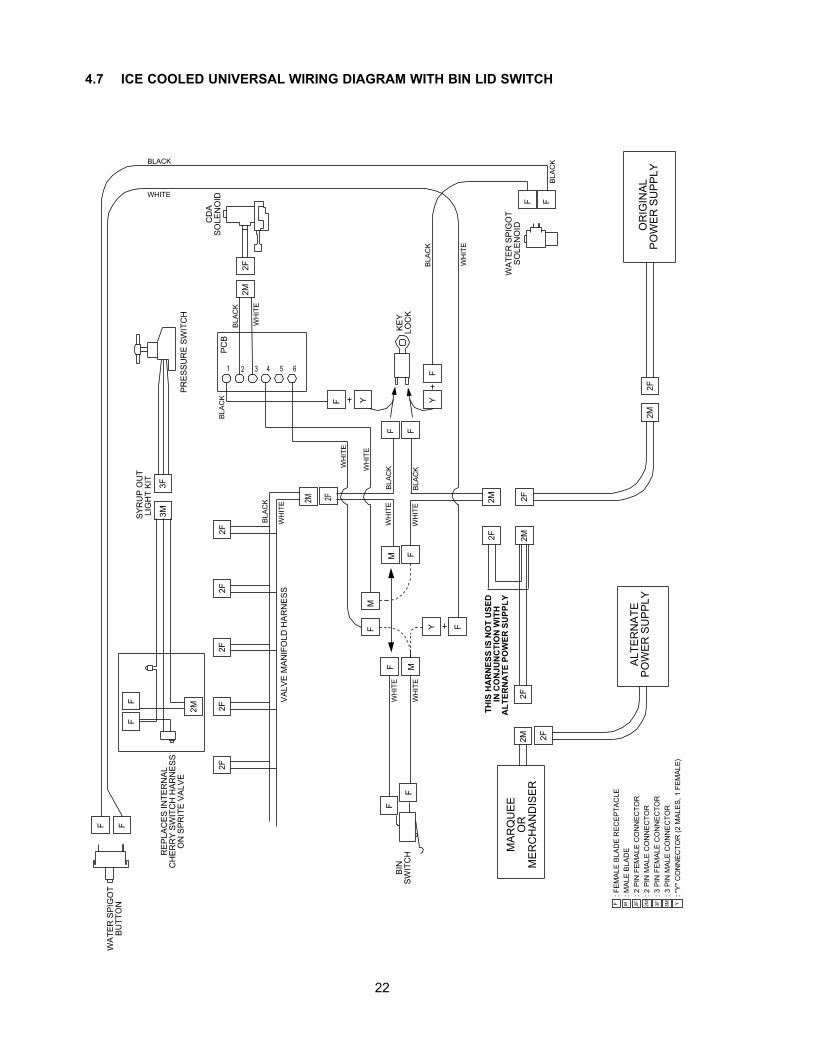
4.7 ICE COOLED UNIVERSAL WIRING DIAGRAM WITH BIN LID SWITCH
2F2F
2F2F
2F
MF: F
EMAL
E BL
ADE
REC
EPTA
CLE
: MAL
E BL
ADE
: "Y"
CO
NN
ECTO
R (2
MAL
ES, 1
FEM
ALE)
Y
2M
2F
F FKE
Y�LO
CK
F
2M
BLAC
KW
HIT
E
BLAC
K
: 2 P
IN F
EMAL
E C
ON
NEC
TOR
2F
: 2 P
IN M
ALE
CO
NN
ECTO
R2M 3M3F
: 3 P
IN M
ALE
CO
NN
ECTO
R: 3
PIN
FEM
ALE
CO
NN
ECTO
R
2F
OR
IGIN
AL�
POW
ER S
UPP
LY2M
BLAC
K
WH
ITE
2M2F
2F M
ARQ
UEE
�O
R�
MER
CH
AND
ISER
ALTE
RN
ATE�
POW
ER S
UPP
LY2F
2M
F F
FF
FY
WAT
ER S
PIG
OT�
SOLE
NO
ID
WAT
ER S
PIG
OT�
BUTT
ON
WH
ITE
BLAC
K
FY
BLACK
WHITE
BLAC
K
VALV
E M
ANIF
OLD
HAR
NES
S
2M
3M3F
FF
SYR
UP
OU
T�LI
GH
T KI
T R
EPLA
CES
INTE
RN
AL�
CH
ERR
Y SW
ITC
H H
ARN
ESS�
ON
SPR
ITE
VALV
E
MF
CD
A�SO
LEN
OID
PRES
SUR
E SW
ITC
H
2FW
HIT
EBL
ACK
PCB
21 543 6
2M
YF
BLAC
K
2F
THIS
HA
RN
ESS
IS N
OT
USE
D�
IN C
ON
JUN
CTI
ON
WIT
H�
ALT
ERN
ATE
PO
WER
SU
PPLY
WH
ITE
WH
ITE
MW
HIT
E
23
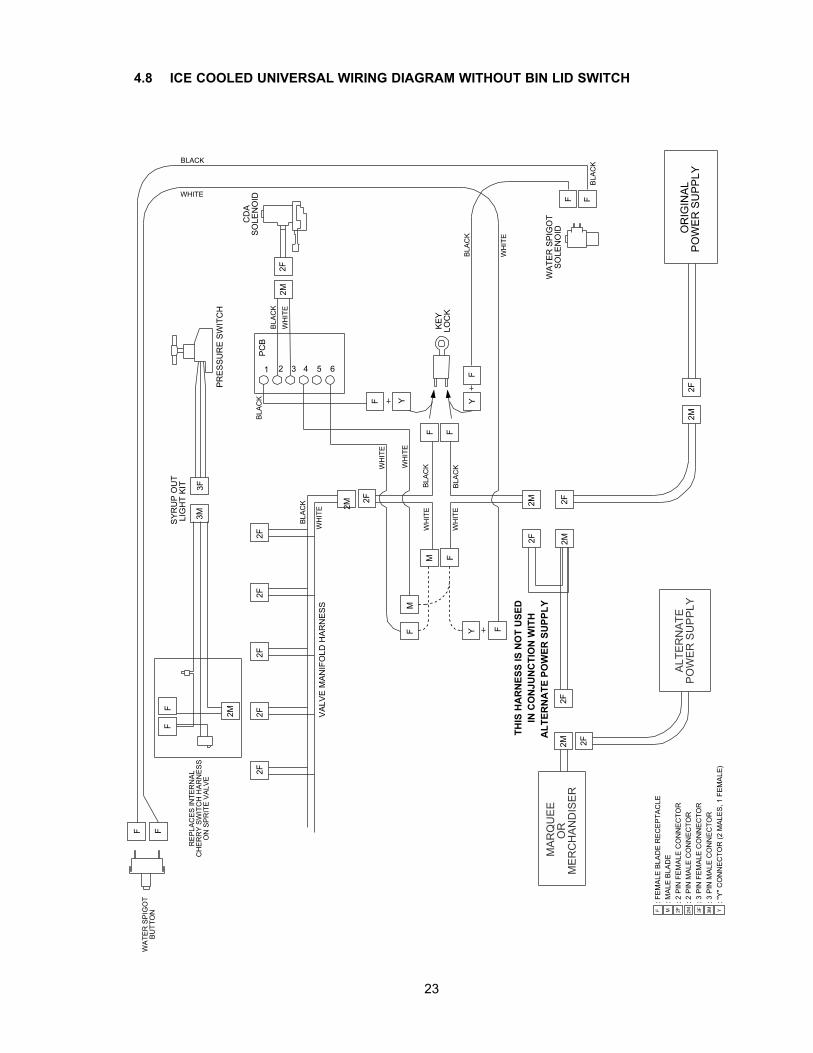
4.8 ICE COOLED UNIVERSAL WIRING DIAGRAM WITHOUT BIN LID SWITCH
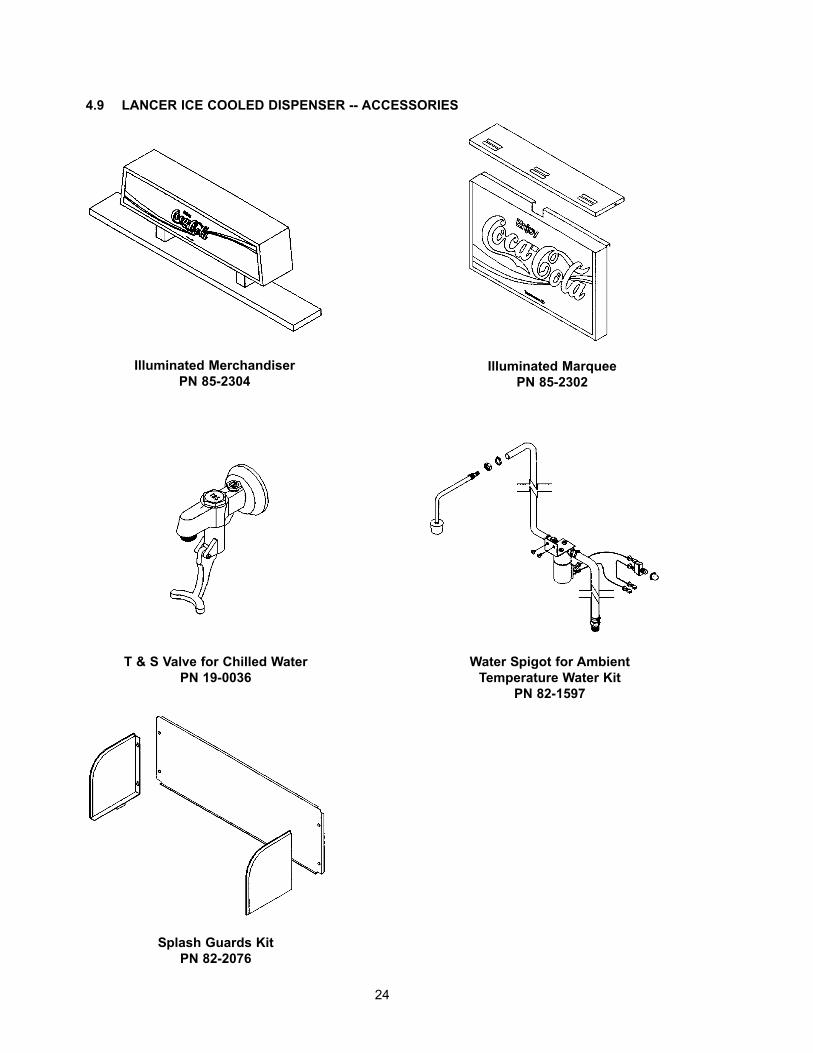
4.9 LANCER ICE COOLED DISPENSER -- ACCESSORIES
24
Illuminated MerchandiserPN 85-2304
Illuminated MarqueePN 85-2302
T & S Valve for Chilled WaterPN 19-0036
Water Spigot for AmbientTemperature Water Kit
PN 82-1597
Splash Guards KitPN 82-2076
Directory of USA - Canada Offices,International Offices, and Authorized Distributors (Continued)
(Continued from previous page)EcuaLancer S.A. - EcuadorLancer Sales CompanyContact: Luciano LopezSector Las AcaciasLuis De Beethoven #958Y Capitan Rafael RamosQuito, EcuadorPhone: 593-22-401-598, 400-937, 406-418FAX: 593-22-400-535e-mail: [email protected] Authorized DistributorsEximport & Barter Co. - Caribbean2101 S.W. 56th TerraceHollywood, FL 33023 USAPhone: (954) 967-9999FAX: (954) 967-9900e-mail: [email protected], S.A. - ArgentinaContact: Rafael MendozaJuncal 858 - Piso 3 Depto. “L”(1062) Buenos AiresArgentinaPhone: (54.11)4394.7654FAX: (54.11)4394.1193e-mail: [email protected] Sulamericana LTDA. - BrasilContact: Fabio QueirozRua. Dr. Ladislau Retti, 1400Parque AlexandreCotia Sao Paulo - BrasilCEP: 06714-150Phone: 55-11-4612-1122FAX: 55-11-4612-2219e-mail: [email protected] Chile Ltda. - ChileContact: Heriberto ConchaVicuna Mackenna 3019, San JoaquinSantiago, ChilePhone: 56-2-552-1657FAX: 56-2-552-1961e-mail: [email protected] PacificInternational Sales6655 Lancer Blvd.San Antonio, TX 78219Phone: (210) 310-7000FAX: (210) 310-72421-800-729-1500e-mail: [email protected] Pacific Pty Ltd5 Toogood AvenueBeverley 5009South AustraliaPhone: 61-8-8268-1388FAX: 61-8-8268-1978e-mail: [email protected]
[email protected](for Fountain)[email protected](for Beer)[email protected](Senior Director - Asia)
Lancer Pacific Pty Ltd7 Slough AvenueSilverwater 2128New South WalesAustraliaPhone: 61-2-9648-6840FAX: 61-2-9648-6850e-mail: richard-abraham@lancer-
pacific.com.au
Lancer Pacific Pty Ltd55 Keele StreetCollingwood 3066VictoriaAustraliaPhone: 03 8415 1920FAX: 03 8415 1929e-mail: [email protected] Pacific Pty LtdUnit 31, 284 Musgrave DriveCoopers Plains 4108QueenslandAustraliaPhone: 61-7-3274-5700FAX: 61-7-3875-1805e-mail: [email protected] ZealandLancer Pacific Ltd9 O’Rorke StreetOnehunga, AucklandNew ZealandPhone: 64-9-634-3612FAX: 64-9-634-1472e-mail: [email protected] KongPatrick Co - Area Manager - AsiaPhone: 852-29670900FAX: 852-30105882e-mail: [email protected] Authorized DistributorsShanghai Freser International Co Ltd. -China1856, Hu Tai RoadShanghai, 200436, ChinaPhone: 86-21-5650-3555FAX: 86-21-5650-2666e-mail: [email protected] (HK) Company Ltd - Hong KongFlat A, 24/F., Houston Industrial Bldg.32-40 Wang Lung StreetTsuen Wan, N. T., Hong KongPhone: 852-2408-2595FAX: 852-2408-2605e-mail: [email protected]. Ciptapratama Sentosamakmur -IndonesiaJI. Anggrek Nelly Murni, Blok A - 39, SlipiJakarta 11480, IndonesiaPhone: 62-21-532-3737FAX: 62-21-532-3666e-mail: [email protected] Sanki - JapanHayakawa Sanki, Inc.1-13-13, Kayaba-choNihonbashi, Chuo-kuTokyo, 103-0025JapanPhone: 03-5651-1481FAX: 03-5651-1445e-mail: [email protected] Corporation - KoreaTahoe Corporation2FL, 835-66 Yocksam-dongKangnam-KuSeoul, KoreaPhone: 82-2-557-5612, -5614FAX: 82-2-557-5615e-mail: [email protected] (MALAYSIA) SDN. BHD. - MalaysiaNo. 31, Jalan TPP 5/13, TamanPerindustrian Puchong, Seksyen 5,47100 Puchong, Selangor, MalaysiaPhone: 60-3-8061-6666FAX: 60-3-8062-1007e-mail: [email protected]
R.B.P. Industrial Sales Inc - PhilippinesUnit 20, Facilities Centre Bldg.548 Shaw BlvdMandaluyong City, PhilippinesPhone: 632-531-1215/1221/1289FAX: 632-531-1271e-mail: [email protected] (S) Pte Ltd - SingaporeBlk 998 Toa Payoh North#04-12/14Singapore 318993Phone: 65-6352-0943FAX: 65-6352-8594e-mail: [email protected] International Corporation - TaiwanNo. 76, Gui-Sui StreetTaipei 103, Taiwan R.O.C.Phone: 886-2-2553-1555FAX: 886-2-2553-2742e-mail: [email protected] (Thailand) Co Ltd - Thailand3/15 Moo 3, Soi RuammitrTivanont Road, BanmaiPakkred, Nonthaburi, 11120ThailandPhone: 662-961-9543FAX: 662-961-9550e-mail: [email protected] - Indian Sub-ContinentIndiaShabbir Shafiqui - Area Manager
India and Sub-ContinentB-7, Pannalal Silk Mill Compounds78, LBS Marg, Bhandup (W)Mumbai 400-078, IndiaPhone: 91-22-2561-6665Cel No.: 91-98-2029-5252FAX: 91-22-5637-4018e-mail: [email protected] Authorized DistributorsWestern Refrigeration Ltd - IndiaB-7, Pannalal Silk Mill Compounds78 L.B.S. Marg, Bhandup (W)Mumbai 400-078, IndiaPhone: 91-22-2561-6665FAX: 91-22-2562-2257e-mail: [email protected] Marketing Company - BangladeshSkylark Point (6th Floor)Room #G-224/A Bijoy Nagar,Dhaka-1000, BangladeshPhone: 880-2-934-2987FAX: 880-2-935-0127e-mail: [email protected] Equipment - PakistanDynamic Equipment and Controls (Pvt.) Ltd.F-1/23, Canal Cottages, Block-D.New Muslim Town.Lahore. Pakistan.Phone: 0092-42-583-6737
0092-42-583-6787FAX: 0092-42-586-7924e-mail: [email protected]
25
Lancer RussiaLancer Sales CompanyVyatskaya Street 27Building 15, 4th Floor125015 Moscow, RussiaPhone: 7-095-745-7108FAX: 7-095-745-7109Mobile Phone: 7-095-991-7778
7-095-139-0335e-mail: [email protected]
[email protected] Middle East / AfricaElsayed Moniem - Technical ManagerLancer Middle East/Africa7 Mubarak StreetEast Ain Shams 11311Cairo, EgyptPhone/FAX: 2-02-49-35-395Mobile Phone (GSM): 2-010-500-4007e-mail: [email protected] Authorized DistributorDispenseTech - South AfricaP.O. Box 17495Sunward Park, 1470South AfricaPhone: 27-11-397-7455FAX: 27-11-397-7648e-mail: [email protected] Latin AmericaLatin America Sales6655 Lancer Blvd.San Antonio, TX 78219Phone: (210) 310-7000FAX: (210) 310-72451-800-729-1500e-mail: [email protected] de México, S.A. de C.V.Contact: Gerardo CanalesCalle Lerdo De Tejada #544 PTE.Col. Las VillasSan Nicolas De Los Garza, N.L.Monterrey, N. L., México C.P. 66422Phone: (52)-81-83-52-85-32Phone: (52)-81-83-52-85-34Phone: (52)-81-83-52-53-60FAX: (52)-81-83-32-54-10e-mail: [email protected] de México, S.A. de C.V.Branch Office, Mexico CityContact: Carlos LopezLancer de Mexico S.A. de C.V.Sucursal Mexico D.F.Calle: Centeotl No. 112Colonia: La PreciosaDelegacion: AzcapotzalcoMexico D.F. C.P. 02460Phone: (52)-55-53-53-89-28Phone: (52)-55-53-53-89-26Phone: (52)-55-53-53-88-60Phone: (52)-55-53-53-88-21FAX: (52)-55-53-52-46-30e-mail: [email protected] de México, Branch Office, Cd.JuarezContact: Yolanda PugaLancer de MexicoCamino de la Lomas # 4380Col. Partido IglesiasCd. Juarez, CHIH, C.P. 32617MéxicoPhone and FAX: 521-605-00-86Phone: 521-605-00-87e-mail: [email protected](Continued on reverse)
Ernest F. Mariani Company614 West 600 SouthSalt Lake City, UT 84104Phone: (801) 359-3744FAX: (801) 531-9615e-mail: [email protected], or
[email protected] Powers & Company, Inc.P.O. Box 721821 Henry StreetGuntersville, AL 35976Phone: (256) 582-6620FAX: (256) 582-8533e-mail: [email protected] Supply, Inc.843 Rainier Avenue SouthSeattle, WA 98144Phone: (206) 323-8640FAX: (206) 323-9286e-mail: [email protected] Ltd.5122 Timberlea Blvd.Mississauga, Ontario L4W 2S5CanadaPhone: 905-602-5800FAX: 905-602-5804e-mail: [email protected] (B.C.) Ltd.16-8125 - 130th StreetSurrey, B.C. V3W 7X4CanadaPhone: 604-590-4022FAX: 604-590-1601Lancer EuropeBelgium - European Central OfficeLancer Europe, S.A.Mechelsesteenweg 592B-1930 ZaventemBelgiumPhone: 32-2-755-2390FAX: 32-2-755-2399e-mail: [email protected] Bembridge GardensRuislip, MiddlesexHA4 7ER, EnglandPhone: 44-1895672667FAX: 44-1895637537e-mail: [email protected] GödöllõIsaszegi út 67HungaryPhone: 36-28-417-179FAX: 36-28416-881e-mail: [email protected] Authorized DistributorsComplete Beverage Services, Ltd.Republic of Ireland and Northern IrelandGortrush Industrial EstateOmagh County TyroneNorthern IrelandOffice: 44-1662 250 008FAX: 44-1662-252-991Intercom - SpainIntercomAvda. Concha Espina 828036 Madrid SpainPhone: 34-91-564 6900FAX: 34-91-564 3065e-mail: [email protected]
Lancer USAManufacturing LocationsFoster Road Facilities6655 Lancer BlvdSan Antonio, TX 78219Phone: (210) 310-7000MFG FAX: (210) 310-7088ENG FAX: (210) 310-7096ACCT FAX: (210) 310-7091PURCH FAX: (210) 310-7094Lancer FBD5620 Business ParkSan Antonio, TX 78218Phone: (210) 666-0544FAX: (210) 666-2044Lancer Ice Link6655 Lancer BlvdSan Antonio, TX 78219Phone: (210) 310-7174FAX: (210) 310-7245Remanufacturing6655 Lancer BlvdSan Antonio, TX 78219Phone: (210) 310-7356FAX: (210) 310-72611-800-729-1550Lancer North AmericaUSA - Canada Sales6655 Lancer Blvd.San Antonio, TX 78219Phone: (210) 310-7000SALES FAX: (210) 310-7245CUSTOMER SERVICE FAX: (210) 310-72501-800-729-1500Georgia Office1125 Northmeadow Parkway, Suite 116Roswell, GA 30076Phone: (770) 343-8828FAX: (770) 475-86461-800-729-1750Lancer Authorized DistributorsAdvanced Beverage Solutions (ABS)100 N. Gary Avenue, Suite CRoselle, IL 60172Phone: (847) 524-1707
(877) 814-2271FAX: (847) 524-1710www.absone.comBevco6900 Camille AvenueOklahoma City, OK 73149Phone: (405) 672-7770FAX: (405) 672-7443e-mail: [email protected] Kirwan Company119 White Oak LaneOld Bridge, NJ 08857Phone: (732) 679-1900FAX: (732) 679-9236e-mail: [email protected] & M Beverage Equipment Co. Inc.12510 Santa Fe Trail DriveLenexa, KS 66215Phone: (913) 888-8988FAX: (913) 888-9137e-mail: [email protected](Update #44 - as of May 01, 2003)
Directory of USA - Canada Offices,International Offices, and Authorized Distributors
Corporate Office6655 Lancer Blvd. • San Antonio, Texas 78219 • 210-310-7000 • 1-800-729-1500 • FAX 210-310-7250
26