Embed Size (px)
DESCRIPTION
10 Rock Excavation Handbook Rock Excavation
Citation preview
CRACK PROPAGATION
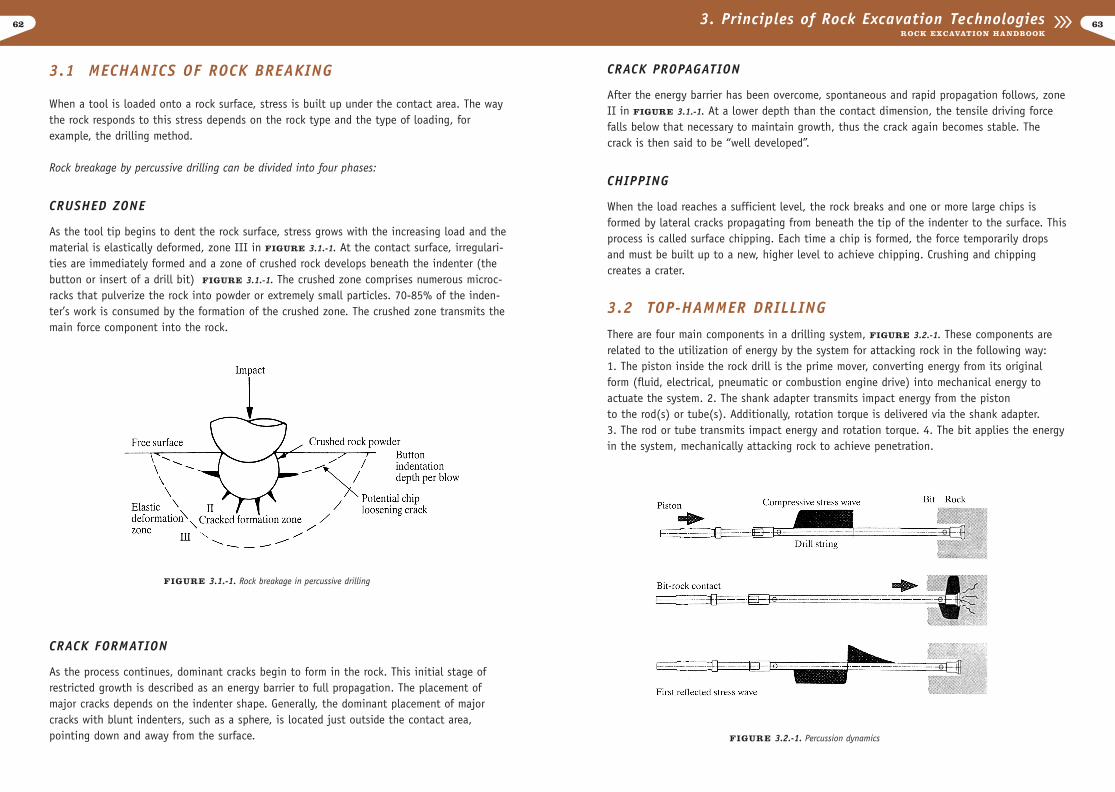
After the energy barrier has been overcome, spontaneous and rapid propagation follows, zoneII in FIGURE 3.1.-1. At a lower depth than the contact dimension, the tensile driving forcefalls below that necessary to maintain growth, thus the crack again becomes stable. Thecrack is then said to be “well developed”.
CHIPPING
When the load reaches a sufficient level, the rock breaks and one or more large chips isformed by lateral cracks propagating from beneath the tip of the indenter to the surface. Thisprocess is called surface chipping. Each time a chip is formed, the force temporarily dropsand must be built up to a new, higher level to achieve chipping. Crushing and chippingcreates a crater.
3.2 TOP-HAMMER DRILLING
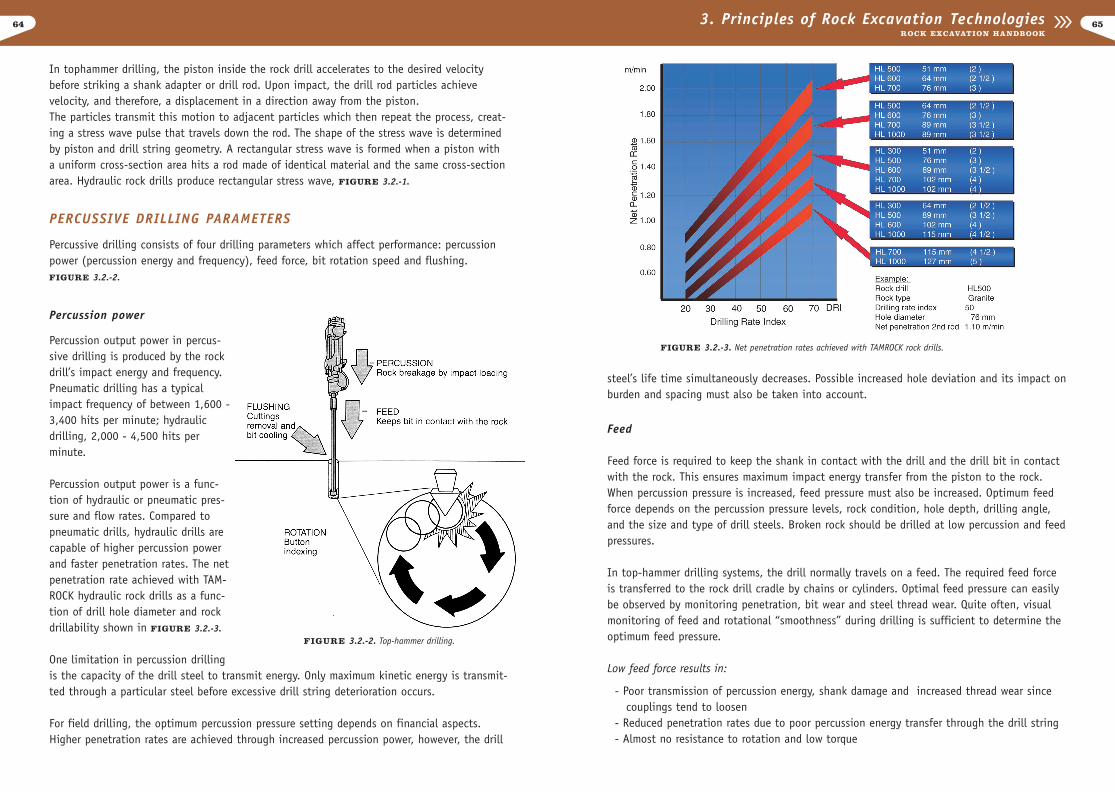
There are four main components in a drilling system, FIGURE 3.2.-1. These components arerelated to the utilization of energy by the system for attacking rock in the following way: 1. The piston inside the rock drill is the prime mover, converting energy from its originalform (fluid, electrical, pneumatic or combustion engine drive) into mechanical energy toactuate the system. 2. The shank adapter transmits impact energy from the piston to the rod(s) or tube(s). Additionally, rotation torque is delivered via the shank adapter. 3. The rod or tube transmits impact energy and rotation torque. 4. The bit applies the energyin the system, mechanically attacking rock to achieve penetration.
3.1 MECHANICS OF ROCK BREAKING
When a tool is loaded onto a rock surface, stress is built up under the contact area. The waythe rock responds to this stress depends on the rock type and the type of loading, for example, the drilling method.
Rock breakage by percussive drilling can be divided into four phases:
CRUSHED ZONE
As the tool tip begins to dent the rock surface, stress grows with the increasing load and thematerial is elastically deformed, zone III in FIGURE 3.1.-1. At the contact surface, irregulari-ties are immediately formed and a zone of crushed rock develops beneath the indenter (thebutton or insert of a drill bit) FIGURE 3.1.-1. The crushed zone comprises numerous microc-racks that pulverize the rock into powder or extremely small particles. 70-85% of the inden-ter’s work is consumed by the formation of the crushed zone. The crushed zone transmits themain force component into the rock.
CRACK FORMATION
As the process continues, dominant cracks begin to form in the rock. This initial stage ofrestricted growth is described as an energy barrier to full propagation. The placement ofmajor cracks depends on the indenter shape. Generally, the dominant placement of majorcracks with blunt indenters, such as a sphere, is located just outside the contact area, pointing down and away from the surface.
6362 3. Principles of Rock Excavation TechnologiesROCK EXCAVATION HANDBOOK
FIGURE 3.1.-1. Rock breakage in percussive drilling
FIGURE 3.2.-1. Percussion dynamics
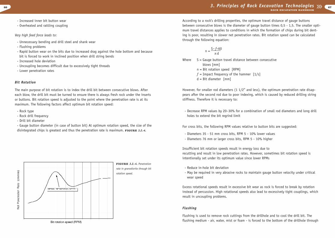
steel’s life time simultaneously decreases. Possible increased hole deviation and its impact onburden and spacing must also be taken into account.
Feed
Feed force is required to keep the shank in contact with the drill and the drill bit in contactwith the rock. This ensures maximum impact energy transfer from the piston to the rock.When percussion pressure is increased, feed pressure must also be increased. Optimum feedforce depends on the percussion pressure levels, rock condition, hole depth, drilling angle,and the size and type of drill steels. Broken rock should be drilled at low percussion and feedpressures.
In top-hammer drilling systems, the drill normally travels on a feed. The required feed forceis transferred to the rock drill cradle by chains or cylinders. Optimal feed pressure can easilybe observed by monitoring penetration, bit wear and steel thread wear. Quite often, visualmonitoring of feed and rotational “smoothness” during drilling is sufficient to determine the optimum feed pressure.
Low feed force results in:
- Poor transmission of percussion energy, shank damage and increased thread wear since couplings tend to loosen
- Reduced penetration rates due to poor percussion energy transfer through the drill string- Almost no resistance to rotation and low torque
In tophammer drilling, the piston inside the rock drill accelerates to the desired velocitybefore striking a shank adapter or drill rod. Upon impact, the drill rod particles achievevelocity, and therefore, a displacement in a direction away from the piston. The particles transmit this motion to adjacent particles which then repeat the process, creat-ing a stress wave pulse that travels down the rod. The shape of the stress wave is determinedby piston and drill string geometry. A rectangular stress wave is formed when a piston witha uniform cross-section area hits a rod made of identical material and the same cross-sectionarea. Hydraulic rock drills produce rectangular stress wave, FIGURE 3.2.-1.
PERCUSSIVE DRILLING PARAMETERS
Percussive drilling consists of four drilling parameters which affect performance: percussionpower (percussion energy and frequency), feed force, bit rotation speed and flushing. FIGURE 3.2.-2.
Percussion power
Percussion output power in percus-sive drilling is produced by the rockdrill’s impact energy and frequency.Pneumatic drilling has a typicalimpact frequency of between 1,600 -3,400 hits per minute; hydraulicdrilling, 2,000 - 4,500 hits perminute.
Percussion output power is a func-tion of hydraulic or pneumatic pres-sure and flow rates. Compared topneumatic drills, hydraulic drills arecapable of higher percussion powerand faster penetration rates. The netpenetration rate achieved with TAM-ROCK hydraulic rock drills as a func-tion of drill hole diameter and rockdrillability shown in FIGURE 3.2.-3.
One limitation in percussion drillingis the capacity of the drill steel to transmit energy. Only maximum kinetic energy is transmit-ted through a particular steel before excessive drill string deterioration occurs.
For field drilling, the optimum percussion pressure setting depends on financial aspects.Higher penetration rates are achieved through increased percussion power, however, the drill
6564 3. Principles of Rock Excavation TechnologiesROCK EXCAVATION HANDBOOK
FIGURE 3.2.-2. Top-hammer drilling.
FIGURE 3.2.-3. Net penetration rates achieved with TAMROCK rock drills.
According to a rock’s drilling properties, the optimum travel distance of gauge buttonsbetween consecutive blows is the diameter of gauge button times 0,5 - 1,5. The smaller opti-mum travel distances applies to conditions in which the formation of chips during bit dent-ing is poor, resulting in slower net penetration rates. Bit rotation speed can be calculatedthrough the following equation:
n = S ƒ 60
¹ d
Where S = Gauge button travel distance between consecutiveblows [mm]
n = Bit rotation speed [RPM]ƒ = Impact frequency of the hammer [1/s]d = Bit diameter [mm]
However, for smaller rod diameters (1 1/2” and less), the optimum penetration rate disap-pears after the second rod due to poor indexing, which is caused by reduced drilling string stiffness. Therefore it is necessary to:
- Decrease RPM values by 20–30% for a combination of small rod diameters and long drillholes to extend the bit regrind limit
For cross bits, the following RPM values relative to button bits are suggested:
- Diameters 35 - 51 mm cross bits, RPM 5 - 10% lower values - Diameters 76 mm or larger cross bits, RPM 5 - 10% higher
Insufficient bit rotation speeds result in energy loss due to recutting and result in low penetration rates. However, sometimes bit rotation speed isintentionally set under its optimum value since lower RPMs
- Reduce in-hole bit deviation- May be required in very abrasive rocks to maintain gauge button velocity under critical
wear speed
Excess rotational speeds result in excessive bit wear as rock is forced to break by rotationinstead of percussion. High rotational speeds also lead to excessively tight couplings, whichresult in uncoupling problems.
Flushing
Flushing is used to remove rock cuttings from the drillhole and to cool the drill bit. Theflushing medium - air, water, mist or foam - is forced to the bottom of the drillhole through
- Increased inner bit button wear- Overheated and rattling coupling
Very high feed force leads to:
- Unnecessary bending and drill steel and shank wear- Flushing problems- Rapid button wear on the bits due to increased drag against the hole bottom and because
bit is forced to work in inclined position when drill string bends- Increased hole deviation- Uncoupling becomes difficult due to excessively tight threads- Lower penetration rates
Bit Rotation
The main purpose of bit rotation is to index the drill bit between consecutive blows. Aftereach blow, the drill bit must be turned to ensure there is always fresh rock under the insertsor buttons. Bit rotation speed is adjusted to the point where the penetration rate is at itsmaximum. The following factors affect optimum bit rotation speed:
- Rock type- Rock drill frequency- Drill bit diameter- Gauge button diameter (in case of button bit) At optimum rotation speed, the size of thedisintegrated chips is greatest and thus the penetration rate is maximum. FIGURE 3.2.-4.
6766 3. Principles of Rock Excavation TechnologiesROCK EXCAVATION HANDBOOK
FIGURE 3.2.-4. Penetration
rate in granodiorite through bit
rotation speed.
• •
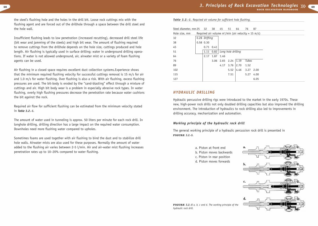
Table 3.2.-1. Required air volume for sufficient hole flushing.
Steel diameter, mm 25 32 38 45 51 64 76 87
Hole size, mm Required air volume m3/min (air velocity = 15 m/s)
32 0.28 Drifting
38 0.58 0.30
45 0.71 0.41
51 1.11 0.82 Long hole drilling
64 2.17 1.87 1.46
76 3.06 2.65 2.24 1.19 Tubes
89 4.17 3.76 2.70 1.52
102 5.52 4.46 3.27 2.00
115 7.51 5.27 4.00
127 6.05
HYDRAULIC DRILLING
Hydraulic percussive drilling rigs were introduced to the market in the early 1970s. Thesenew, high-power rock drills not only doubled drilling capacities but also improved the drilling environment. The introduction of hydraulics to rock drilling also led to improvements indrilling accuracy, mechanization and automation.
Working principle of the hydraulic rock drill
The general working principle of a hydraulic percussion rock drill is presented in FIGURE 3.2.-5.
the steel’s flushing hole and the holes in the drill bit. Loose rock cuttings mix with theflushing agent and are forced out of the drillhole through a space between the drill steel andthe hole wall.
Insufficient flushing leads to low penetration (increased recutting), decreased drill steel life(bit wear and jamming of the steels) and high bit wear. The amount of flushing required to remove cuttings from the drillhole depends on the hole size, cuttings produced and holelength. Air flushing is typically used in surface drilling; water in underground drilling opera-tions. If water is not allowed underground, air, airwater mist or a variety of foam flushingagents can be used.
Air flushing in a closed space requires excellent dust collection systems.Experience showsthat the minimum required flushing velocity for successful cuttings removal is 15 m/s for airand 1.0 m/s for water flushing. Over flushing is also a risk. With air flushing, excess flushingpressures are used. The bit-body is eroded by the “sand-blasting” effect through a mixture ofcuttings and air. High bit body wear is a problem in especially abrasive rock types. In waterflushing, overly high flushing pressures decrease the penetration rate because water cushionsthe bit against the rock.
Required air flow for sufficient flushing can be estimated from the minimum velocity statedin Table 3.2.-1.
The amount of water used in tunneling is approx. 50 liters per minute for each rock drill. Inlonghole drilling, drilling direction has a large impact on the required water consumption.Downholes need more flushing water compared to upholes.
Sometimes foams are used together with air flushing to bind the dust and to stabilize drillhole walls. Airwater mists are also used for these purposes. Normally the amount of wateradded to the flushing air varies between 2-5 l/min. Air and air-water mist flushing increasespenetration rates up to 10–20% compared to water flushing.
6968 3. Principles of Rock Excavation TechnologiesROCK EXCAVATION HANDBOOK
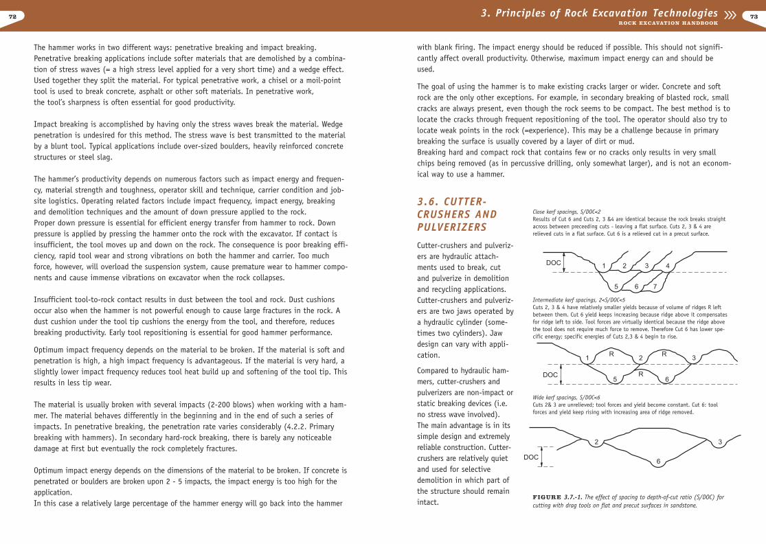
FIGURE 3.2.-5 a, b, c and d. The working principle of thehydraulic rock drill.
a. Piston at front end b. Piston moves backwardsc. Piston in rear position d. Piston moves forwards

3.3 PRINCIPLE OF DTH DRILLING
DTH (Down-The-Hole) drilling, also known as ITH (In-The-Hole) drilling, is a method in which the percus-sive hammer works in the hole during drilling, asopposed to above the hole in top-hammer drilling.DTH hammers are used in underground benchingoperations.
In DTH hammers, the rock drilling bit is a continua-tion of the shank, which the rock drill piston strikesdirectly. DTH machines are driven by compressed airand require a fairly large compressor to operate effec-tively. Since the piston is in almost direct contactwith the drill bit, little energy is lost. This gives anearly constant penetration rate regardless of holelength. Hole accuracy is also good. DTH machines arelimited by their relatively low penetration rates andpoor mobility, because they require a large separatecompressor. Rotation is usually hydraulic. Energy con-sumption is also large compared to top-hammerdrills.The hole sizes most commonly used for under-ground DTH drilling are 89 - 165 mm in diameter, andcan extend up to 1,100 mm. Hole lengths in under-ground benching operations vary up to 60 meters.(FIGURE 3.3.-1.)
3.4 ROTARY PERCUSSIVEDRILLINGRotary percussive drilling is based on the same rockbreaking principle as top-hammer drilling except thatfeed force, rather than percussion force, is used to dent the rock. When the bit is pressedagainst the rock and rotated, the cutting force promotes chip formation and rock cutting.Cuttings are removed via air or air-mist-flushing. Underground rotary percussive drilling tech-niques are most applicable in soft or semi-soft formations. Rotation and thrust set specialrequirements not only on feed and rotation systems but also on drill steels and tool design.
3.5 HYDRAULIC HAMMERS
Hydraulic hammers are attachments used on standard hydraulic excavators. The weight ofhammers ranges from 80 kg - 7000 kg. The weight range for suitable carriers is from 0.8 -100 tons.
TAMROCK rock drills are designed with a minimum of modules and parts. The hydraulic rockdrill has a reliable percussion cartridge structure, comprising a piston and a distributor. Thisdesign allows large and short flow channels, which ensures maximum flow efficiency. Thecompact modules for percussion, rotation and flushing minimize the number of joints(FIGURE 3.2.-6).
PNEUMATIC DRILLING
Pneumatic rock drills and mechanized pneumatic jumbos were most popular during the 1960sand early 1970s. The power source for the pneumatic rock drill is existing compressed airlines or a portable compressor.
COMPARISON BETWEEN HYDRAULIC AND PNEUMATIC DRILLING
Table 3.2.-2. Comparison between hydraulic and pneumatic drilling.
Hydraulic drilling Pneumatic drillingEfficient Fairly inefficient50% higher drilling capacity Low capacityReliable, constantly high Efficiency level depends on outsideefficiency level supply of air and compressed air
pipeline configurationEasily adjustable to changing Fairly inflexiblerock and drilling conditions, smoother drillingErgonomic Non-ergonomicLess noise, moisture, mist, Noisy, air-water mist, cold air flow,no surrounding temperature uncomfortable workingfluctuation environmentEconomical Low-economy rock drillHigh capacity, independent, Low capacity, non-independent minimal labor versatile and (air lines and compressors), user friendly more labor-intensive
7170 3. Principles of Rock Excavation TechnologiesROCK EXCAVATION HANDBOOK
FIGURE 3.2.-6. Modular design of modern rock drill.
FIGURE 3.3.-1. DTH rock drill.
with blank firing. The impact energy should be reduced if possible. This should not signifi-cantly affect overall productivity. Otherwise, maximum impact energy can and should beused.
The goal of using the hammer is to make existing cracks larger or wider. Concrete and softrock are the only other exceptions. For example, in secondary breaking of blasted rock, smallcracks are always present, even though the rock seems to be compact. The best method is tolocate the cracks through frequent repositioning of the tool. The operator should also try tolocate weak points in the rock (=experience). This may be a challenge because in primarybreaking the surface is usually covered by a layer of dirt or mud.Breaking hard and compact rock that contains few or no cracks only results in very smallchips being removed (as in percussive drilling, only somewhat larger), and is not an econom-ical way to use a hammer.
3.6. CUTTER-CRUSHERS ANDPULVERIZERS
Cutter-crushers and pulveriz-ers are hydraulic attach-ments used to break, cutand pulverize in demolitionand recycling applications.Cutter-crushers and pulveriz-ers are two jaws operated bya hydraulic cylinder (some-times two cylinders). Jawdesign can vary with appli-cation.
Compared to hydraulic ham-mers, cutter-crushers andpulverizers are non-impact orstatic breaking devices (i.e.no stress wave involved).The main advantage is in itssimple design and extremelyreliable construction. Cutter-crushers are relatively quietand used for selectivedemolition in which part ofthe structure should remainintact.
The hammer works in two different ways: penetrative breaking and impact breaking.Penetrative breaking applications include softer materials that are demolished by a combina-tion of stress waves (= a high stress level applied for a very short time) and a wedge effect.Used together they split the material. For typical penetrative work, a chisel or a moil-pointtool is used to break concrete, asphalt or other soft materials. In penetrative work, the tool’s sharpness is often essential for good productivity.
Impact breaking is accomplished by having only the stress waves break the material. Wedgepenetration is undesired for this method. The stress wave is best transmitted to the materialby a blunt tool. Typical applications include over-sized boulders, heavily reinforced concretestructures or steel slag.
The hammer’s productivity depends on numerous factors such as impact energy and frequen-cy, material strength and toughness, operator skill and technique, carrier condition and job-site logistics. Operating related factors include impact frequency, impact energy, breakingand demolition techniques and the amount of down pressure applied to the rock. Proper down pressure is essential for efficient energy transfer from hammer to rock. Downpressure is applied by pressing the hammer onto the rock with the excavator. If contact isinsufficient, the tool moves up and down on the rock. The consequence is poor breaking effi-ciency, rapid tool wear and strong vibrations on both the hammer and carrier. Too muchforce, however, will overload the suspension system, cause premature wear to hammer compo-nents and cause immense vibrations on excavator when the rock collapses.
Insufficient tool-to-rock contact results in dust between the tool and rock. Dust cushionsoccur also when the hammer is not powerful enough to cause large fractures in the rock. Adust cushion under the tool tip cushions the energy from the tool, and therefore, reducesbreaking productivity. Early tool repositioning is essential for good hammer performance.
Optimum impact frequency depends on the material to be broken. If the material is soft andpenetration is high, a high impact frequency is advantageous. If the material is very hard, aslightly lower impact frequency reduces tool heat build up and softening of the tool tip. Thisresults in less tip wear.
The material is usually broken with several impacts (2-200 blows) when working with a ham-mer. The material behaves differently in the beginning and in the end of such a series ofimpacts. In penetrative breaking, the penetration rate varies considerably (4.2.2. Primarybreaking with hammers). In secondary hard-rock breaking, there is barely any noticeabledamage at first but eventually the rock completely fractures.
Optimum impact energy depends on the dimensions of the material to be broken. If concrete ispenetrated or boulders are broken upon 2 - 5 impacts, the impact energy is too high for theapplication. In this case a relatively large percentage of the hammer energy will go back into the hammer
7372 3. Principles of Rock Excavation TechnologiesROCK EXCAVATION HANDBOOK
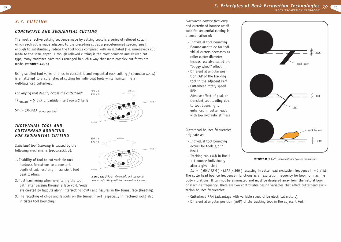
Close kerf spacings, S/DOC<2Results of Cut 6 and Cuts 2, 3 &4 are identical because the rock breaks straightacross between preceeding cuts - leaving a flat surface. Cuts 2, 3 & 4 arerelieved cuts in a flat surface. Cut 6 is a relieved cut in a precut surface.
Intermediate kerf spacings, 2<S/DOC<5Cuts 2, 3 & 4 have relatively smaller yields because of volume of ridges R leftbetween them. Cut 6 yield keeps increasing because ridge above it compensatesfor ridge left to side. Tool forces are virtually identical because the ridge abovethe tool does not require much force to remove. Therefore Cut 6 has lower spe-cific energy; specific energies of Cuts 2,3 & 4 begin to rise.
Wide kerf spacings, S/DOC<6Cuts 2& 3 are unrelieved; tool forces and yield become constant. Cut 6: toolforces and yield keep rising with increasing area of ridge removed.
FIGURE 3.7.-1. The effect of spacing to depth-of-cut ratio (S/DOC) for cutting with drag tools on flat and precut surfaces in sandstone.
74 753. Principles of Rock Excavation TechnologiesROCK EXCAVATION HANDBOOK
Cutterhead bounce frequencyand cutterhead bounce ampli-tude for sequential cutting isa combination of:
- Individual tool bouncing- Bounce amplitude for indi-
vidual cutters decreases asroller cutter diameter increas es; also called the “buggy wheel” effect
- Differential angular position (AP of the tracking tool in the adjacent kerf
- Cutterhead rotary speedRPM
- Adverse affect of peak or transient tool loading due to tool bouncing is enhanced in cutterheads with low hydraulic stifness
Cutterhead bounce frequenciesoriginate as:
- Individual tool bouncing occurs for tools a,b in line i
- Tracking tools a,b in line i + 1 bounce individually after a given time Æt = ( 60 / RPM ) • (ÆAP / 360 ) resulting in cutterhead excitation frequency f = 1 / Æt
The cutterhead bounce frequency f functions as an excitation frequency for boom or machinebody vibrations. It can not be eliminated and must be designed away from the natural boomor machine frequency. There are two controllable design variables that affect cutterhead exci-tation bounce frequencies:
- Cutterhead RPM (advantage with variable speed-drive electrical motors).- Differential angular position (ÆAP) of the tracking tool in the adjacent kerf.
3.7. CUTTING
CONCENTRIC AND SEQUENTIAL CUTTING
The most effective cutting sequence made by cutting tools is a series of relieved cuts, inwhich each cut is made adjacent to the preceding cut at a predetermined spacing smallenough to substantially reduce the tool focus compared with an isolated (i.e. unrelieved) cutmade to the same depth. Although relieved cutting is the most common and desired cuttype, many machines have tools arranged in such a way that more complex cut forms aremade. (FIGURE 3.7.-1.)
Using scrolled tool vanes or lines in concentric and sequential rock cutting / (FIGURE 3.7.-2.)is an attempt to ensure relieved cutting for individual tools while maintaining awell-balanced cutterhead.
For varying tool density across the cutterhead:
TPLmean = · disk or carbide insert rows/· kerfs
SPR = (360/ÆAPscrolls per line)
INDIVIDUAL TOOL AND CUTTERHEAD BOUNCING FOR SEQUENTIAL CUTTING
Individual tool bouncing is caused by the following mechanisms (FIGURE 3.7.-3):
1. Inability of tool to cut variable rockhardness formations to a constantdepth of cut, resulting in transient tool peak loading.
2. Tool hammering when re-entering the tool path after passing through a face void. Voidsare created by fallouts along intersecting joints and fissures in the tunnel face (heading).
3. The recutting of chips and fallouts on the tunnel invert (especially in fractured rock) also initiates tool bouncing.
Scroll #2
Scroll #1
D AP toolsSPR = 2TPL = 2
Scroll #2
Scroll #1
D AP toolsSPR = 1TPL = 1
FIGURE 3.7.-2. Concentric and sequential in-line kerf cutting with two scrolled tool vanes.
DOC
DOC
joint
DOC
rock fallout
hard layer
FIGURE 3.7.-3. Individual tool bounce mechanisms.
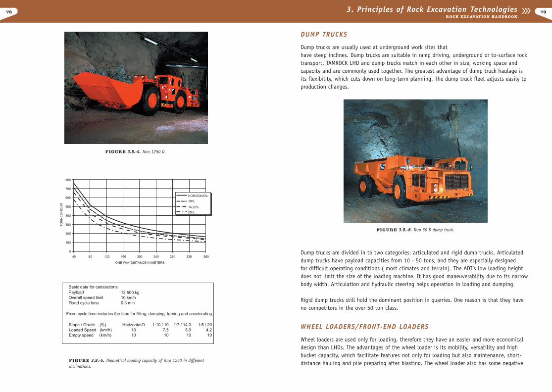
the same engine size, and a long wheel base that gives better stability and allows high tramming speeds with full loads. (FIGURE 3.8.-4. and FIGURE 3.8.-5.)
3.8 LOADING AND HAULING
Any chosen excavation method presents challenges to the loading and hauling system.Machine size can differ greatly in tunnel sites compared to surface sites. LHD machines aremainly used underground, and although seldom used on construction sites, they can also beused on surface sites. The most common loading machines for underground work are wheelloaders. In quarries, hydraulic excavators (including front shovels) and wheel loaders aremost commonly used. Selecting the right machine for the job depends on feed material, pro-duction requirements, operating conditions and following operations.
When selecting a loader, it is important to consider the following:
- Amount rock to be loaded -at quarries, the production requirement- Loading cycle time according to the whole excavation cycle- Size limit due to tunnel- Turning and loading niche availability- Bucket size (Loader bucket size varies according to operating weight. Those which have
small bucket /weight ratio may have higher fill factors than normal.)
LHD MACHINES
In conventional drilling and blasting underground excavation projects, fast and effectivework phases are essential. Drilling, charging, face cleaning and other related functions usual-ly take place at different times. Tunnel advancing depends on the time spent on the criticalpath of each operation. This is the reason why contractors try to minimize it. Fast face clea-ning increases the demand for more effective loader equipment and face cleaning methods.
LHD offers fast and effective face cleaning because it is flexible and versatile. LHD machinesare specially designed and built to load, haul and dump. LHD technology provides a prof-itable solution whether the tunnel is large or small. LHD’s loading philosophy is to clean theface and haul the blasted rock to a secondary muckpile or dump trucks. If trucks are notavailable, LHD dumps the material onto the secondary muckpile, which makes the cleaningeffective.
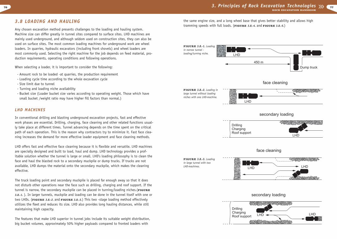
The truck loading point and secondary muckpile is placed far enough away so that it doesnot disturb other operations near the face such as drilling, charging and roof support. If the tunnel is narrow, the secondary muckpile can be placed in turning/loading niches.(FIGURE
3.8.-1. ). In larger tunnels, muckpile and loading can be done in the tunnel itself with one ortwo LHDs. (FIGURE 3.8.-2. and FIGURE 3.8.-3.) This two -stage loading method effectivelyutilizes the fleet and reduces its size. LHD also provides long hauling distances, while stillmaintaining high capacity.
The features that make LHD superior in tunnel jobs include its suitable weight distribution,big bucket volumes, approximately 50% higher payloads compared to fronted loaders with
7776 3. Principles of Rock Excavation TechnologiesROCK EXCAVATION HANDBOOK
FIGURE 3.8.-1. Loading in narrow tunnel - loading/turning niche.
FIGURE 3.8.-2. Loading in large tunnel without loading niches with one LHD-machine.
FIGURE 3.8.-3. Loadingin large tunnel with twoLHD-machines.
78
DUMP TRUCKS
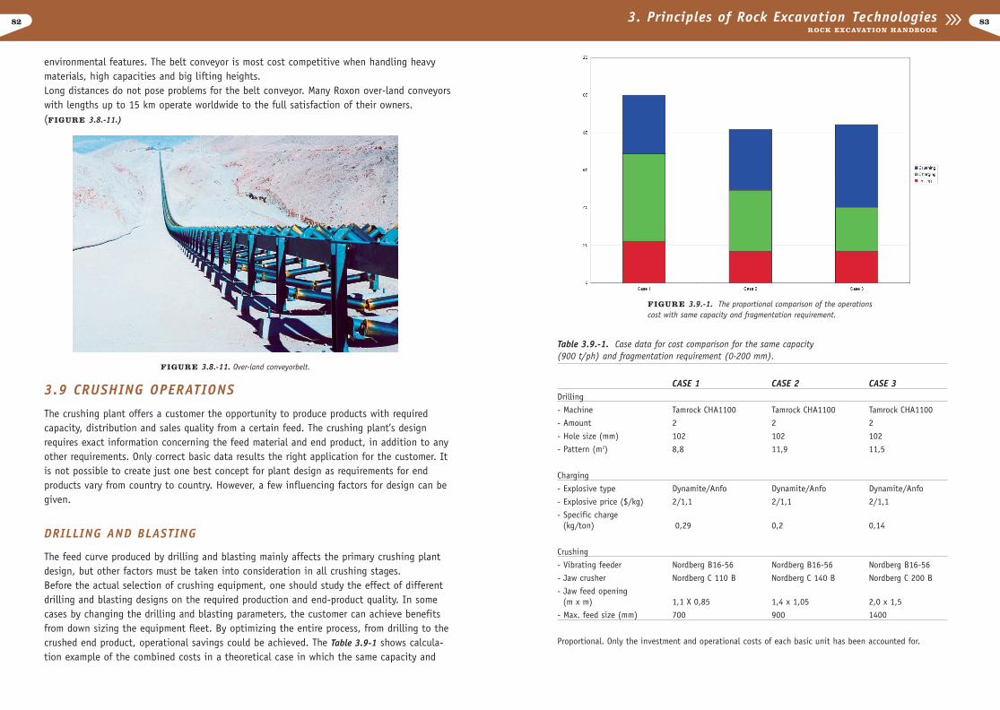
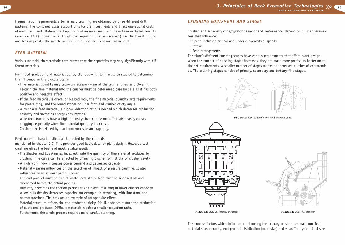
Dump trucks are usually used at underground work sites that have steep inclines. Dump trucks are suitable in ramp driving, underground or to-surface rocktransport. TAMROCK LHD and dump trucks match in each other in size, working space andcapacity and are commonly used together. The greatest advantage of dump truck haulage isits flexibility, which cuts down on long-term planning. The dump truck fleet adjusts easily toproduction changes.
Dump trucks are divided in to two categories: articulated and rigid dump trucks. Articulateddump trucks have payload capacities from 10 - 50 tons, and they are especially designed for difficult operating conditions ( most climates and terrain). The ADT’s low loading heightdoes not limit the size of the loading machine. It has good maneuverability due to its narrowbody width. Articulation and hydraulic steering helps operation in loading and dumping.
Rigid dump trucks still hold the dominant position in quarries. One reason is that they haveno competitors in the over 50 ton class.
WHEEL LOADERS/FRONT-END LOADERS
Wheel loaders are used only for loading, therefore they have an easier and more economicaldesign than LHDs. The advantages of the wheel loader is its mobility, versatility and highbucket capacity, which facilitate features not only for loading but also maintenance, short-distance hauling and pile preparing after blasting. The wheel loader also has some negative
793. Principles of Rock Excavation TechnologiesROCK EXCAVATION HANDBOOK
FIGURE 3.8.-4. Toro 1250 D.
FIGURE 3.8.-5. Theoretical loading capacity of Toro 1250 in differentinclinations.
FIGURE 3.8.-6. Toro 50 D dump truck.

80
- Successful attack of solid that needs blasting before being loaded by wheel loader - Hydraulic excavators operate on rough surface- Wheel excavators move as fast as wheel loaders
A disadvantage is that it requires a separate loader for collecting and preparing the rock pile.
BELT CONVEYORS
Belt conveyors are often the most economical transportation mode. Conveyors have tradition-ally been used for transporting overburden and other materials of limited particle size. Belt conveyors in tunneling and quarrying applications have been limited due to its maximumpractical particle size of approximately 300 mm.
The development of mobile and semi-mobile crushing equipment, which enables crushingclose to the face, has made it possible to switch from hauling by trucks to the more econom-ical method of continuous transportation by belt conveyors. Belt conveyors can be adaptedto any loading method.
Opposed to other transportation methods, the advantages of belt conveying include itsalmost unlimited capacity, low operating costs, often lower total investment costs and
813. Principles of Rock Excavation TechnologiesROCK EXCAVATION HANDBOOK
properties. It needs a solid working floor and well prepared heap. Break force and dumpheight are small compared to hydraulic excavators.
FIGURE 3.8.-7. Wheel loader.
CONTINUOUS LOADING
Continuous loading is a method used at tunneling works. (FIGURE 3.8.-8.) The continuous loader needs either a rail or wheel mounted hauling system.Some continuous loaders have a special application, which loads on tracks, and hauls andtrams on rails. One benefit of the continuous loader is that it does not require turning niches. Its disadvantages include poor mobility, low tramming speed and its inability toeasily handle big boulders. Muck jams also pose problems.
HYDRAULIC EXCAVATORS
Hydraulic excavators can be divided into two different categories:
The first category consists of track (FIGURE 3.8.-9.), wheel model and second categorycomprises the normal digging excavator and front shovel category (FIGURE 3.8.-10.). Frontshovels are divided further into two groups: front dump bucket and bottom dump bucket.
Excavators are mainly used in surface excavation sites. Front shovels are also suitable inlarge tunnels (more than 40 m2). Some advantages for hydraulic excavators include:
FIGURE 3.8.-9. Hydraulic excavator.
FIGURE 3.8.-10 Front shovel.
FIGURE 3.8.-8. Continuous loading to dump truck.
82 833. Principles of Rock Excavation TechnologiesROCK EXCAVATION HANDBOOK
environmental features. The belt conveyor is most cost competitive when handling heavymaterials, high capacities and big lifting heights.Long distances do not pose problems for the belt conveyor. Many Roxon over-land conveyorswith lengths up to 15 km operate worldwide to the full satisfaction of their owners. (FIGURE 3.8.-11.)
3.9 CRUSHING OPERATIONS
The crushing plant offers a customer the opportunity to produce products with requiredcapacity, distribution and sales quality from a certain feed. The crushing plant’s designrequires exact information concerning the feed material and end product, in addition to anyother requirements. Only correct basic data results the right application for the customer. Itis not possible to create just one best concept for plant design as requirements for end products vary from country to country. However, a few influencing factors for design can begiven.
DRILLING AND BLASTING
The feed curve produced by drilling and blasting mainly affects the primary crushing plantdesign, but other factors must be taken into consideration in all crushing stages.Before the actual selection of crushing equipment, one should study the effect of differentdrilling and blasting designs on the required production and end-product quality. In somecases by changing the drilling and blasting parameters, the customer can achieve benefitsfrom down sizing the equipment fleet. By optimizing the entire process, from drilling to thecrushed end product, operational savings could be achieved. The Table 3.9-1 shows calcula-tion example of the combined costs in a theoretical case in which the same capacity and
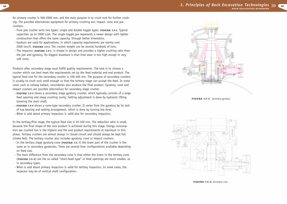
FIGURE 3.9.-1. The proportional comparison of the operationscost with same capacity and fragmentation requirement.
Table 3.9.-1. Case data for cost comparison for the same capacity (900 t/ph) and fragmentation requirement (0-200 mm).
CASE 1 CASE 2 CASE 3Drilling
- Machine Tamrock CHA1100 Tamrock CHA1100 Tamrock CHA1100
- Amount 2 2 2
- Hole size (mm) 102 102 102
- Pattern (m2) 8,8 11,9 11,5
Charging
- Explosive type Dynamite/Anfo Dynamite/Anfo Dynamite/Anfo
- Explosive price ($/kg) 2/1,1 2/1,1 2/1,1
- Specific charge (kg/ton) 0,29 0,2 0,14
Crushing
- Vibrating feeder Nordberg B16-56 Nordberg B16-56 Nordberg B16-56
- Jaw crusher Nordberg C 110 B Nordberg C 140 B Nordberg C 200 B
- Jaw feed opening (m x m) 1,1 X 0,85 1,4 x 1,05 2,0 x 1,5
- Max. feed size (mm) 700 900 1400
Proportional. Only the investment and operational costs of each basic unit has been accounted for.
FIGURE 3.8.-11. Over-land conveyorbelt.
84
CRUSHING EQUIPMENT AND STAGES
Crusher, and especially cone/gyrator behavior and performance, depend on crusher parame-ters that influence:
- Speed including critical and under & overcritical speeds- Stroke- Feed arrangements
The plant’s different crushing stages have various requirements that affect plant design.When the number of crushing stages increases, they are made more precise to better meetthe set requirements. A smaller number of stages means an increased number of compromis-es. The crushing stages consist of primary, secondary and tertiary/fine stages.
The process factors which influence on choosing the primary crusher are: maximum feedmaterial size, capacity, end product distribution (max. size) and wear. The typical feed size
853. Principles of Rock Excavation TechnologiesROCK EXCAVATION HANDBOOK
fragmentation requirements after primary crushing are obtained by three different drill patterns. The combined costs account only for the investments and direct operational costsof each basic unit. Material haulage, foundation investment etc. have been excluded. Results(FIGURE 3.9-1.) shows that although the largest drill pattern (case 3) has the lowest drillingand blasting costs, the middle method (case 2) is most economical in total.
FEED MATERIAL
Various material characteristic data proves that the capacities may vary significantly with dif-ferent materials.
From feed gradation and material purity, the following items must be studied to determinethe influence on the process design.
- Fine material quantity may cause unnecessary wear at the crusher liners and clogging. Feeding the fine material into the crusher must be determined case by case as it has both positive and negative effects.
- If the feed material is gravel or blasted rock, the fine material quantity sets requirements for prescalping, and the round stones on liner form and crusher cavity angle.
- With coarse feed material, a higher reduction ratio is needed which decreases productioncapacity and increases energy consumption.
- Wide feed fractions have a higher density than narrow ones. This also easily causesclogging, especially when fine material quantity is critical.
- Crusher size is defined by maximum rock size and capacity.
Feed material characteristics can be tested by the methods mentioned in chapter 2.7. This provides good basic data for plant design. However, testcrushing gives the best and most reliable results.
- The Shatter and Los Angeles index estimate the quantity of fine material produced by crushing. The curve can be affected by changing crusher rpm, stroke or crusher cavity.
- A high work index increases power demand and decreases capacity.- Material wearing influences on the selection of impact or pressure crushing. It also
influences on what wear part is chosen.- The end product must be free of waste feed. Waste feed must be screened off and
discharged before the actual process.- Humidity decreases the friction particularly in gravel resulting in lower crusher capacity.- A low bulk density decreases capacity, for example, in recycling, with limestone and
narrow fractions. The ores are an example of an opposite effect.- Material structure affects the end product cubicity. Pin-like shapes disturb the production
of cubic end products. Difficult materials require a smaller reduction ratio.Furthermore, the whole process requires more careful planning. FIGURE 3.9.-3. Primary gyratory. FIGURE 3.9.-4. Impactor.
FIGURE 3.9.-2. Single and double toggle jaws.
86 873. Principles of Rock Excavation TechnologiesROCK EXCAVATION HANDBOOK
for primary crusher is 500-2000 mm, and the main purpose is to crush rock for further crush-ing. The possible alternatives equipment for primary crushing are: impact, cone and jawcrushers.
- From jaw crusher exits two types: single and double toggle types. FIGURE 3.9-2. Typical capacities up to 2000 t/ph. The single toggle jaw represents a newer design with lighter construction that offers the same capacity, through better kinematics.
- Gyrators are used for applications, in which capacity requirements are mainly over 2000 ton/h. FIGURE 3.9-3. The crusher weight can be several hundreds of tons.
- The impactor, FIGURE 3.9-4, is simple in design and provides a higher crushing ratio thanthe jaw and gyratory. Its biggest drawback is that liner wear is too high except in very soft rocks.
Products after secondary stage must fulfill quality requirements. The task is to choose acrusher which can best meet the requirements set by the feed material and end product. Thetypical feed size for the secondary crusher is 100-400 mm. The purpose of secondary crushersis usually to crush rock small enough so that the tertiary stage can accept the feed. In somecases such as railway ballast, secondaries also produce the final product. Gyratory, cone andimpact crushers are possible alternatives for secondary stage crusher.
- FIGURE 3.9-5 shows a secondary stage gyratory crusher, which typically consists of a largefeed opening and steep crushing cavity. Setting adjustment is done by hydraulic lifting lowering the main shaft.
- FIGURE 3.9-6 shows a cone-type secondary crusher. It varies from the gyratory by its lack of top bearing and setting arrangement, which is done by turning the bowl.
- What is said about primary impactors is valid also for secondary impactors.
In the tertiary/fine stage, the typical feed size is 10-100 mm. The reduction ratio is small,because the final shape of the rock product is achieved during this stage. Energy consump-tion per crushed ton is the highest and the end product requirements at maximum in thisphase. Tertiary crushers are almost always in closed circuit and should always be kept full(choke fed). The tertiary crusher also includes gyratory, cone or impact crushers.
- In the tertiary stage gyratory-cone (FIGURE 3.9.-7) the lower part of the crusher is the same as in secondary gyratories. There are several liner configurations available dependingon feed size.
- The main difference from the secondary cone is that either the liners in the tertiary cone (FIGURE 3.9.-8) are the so called “short-head type” or feed openings are much smaller, asin secondary types.
- What is said about primary impactors is valid for tertiary impactors. In some cases, the impactor may be of vertical shaft configuration.
FIGURE 3.9.-6. Secondary cone.
FIGURE 3.9.-5. Secondary gyratory.
88
CRUSHING PLANT EXAMPLE
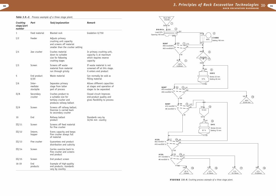
Table 3.9.-2 and FIGURE 3.9-9. on next page show a process example of a three-stage plant.The feed material is blasted stone and the end product is railway ballast (32/64 mm) andfractions (0/5, 5/10, 10/15 and 15/20 mm) and fraction 0/20 mm including impurities isscreened off from the feed material.
CRUSHING PLANT OPTIONS
The flow sheet serves as a model to predict the performance of the plant, arranging the prop-er equipment into a balanced system, resulting in the desired proportions of finished materi-al size. Crusher and screen size is selected according to capacity and product fractionrequirements.
Regarding the crushing selection, the plant designer may choose to fulfill machine require-ments by integrating into the design a:
- stationary (fixed) plant- semi-mobile (skid-mounted) unit- mobile (portable or self-propelled) unit
Each producer is looking for total crushing solutions to fit his own needs. The stationary unitis the preferred solution for a long-term plant and for high demand good-quality product. Theplant is therefore customized according the required process and customer preferences. Themobile unit is the best for customers seeking business from small contracts in the neighbor-hood, other counties and even other countries.
Self-propelled Crushing Units
The self-propelled crushing units are those mobile units which are powered by diesel engineand have tracks as undercarriage system. For primary crushing, the unit is equipped witha vibrating feeder, either with jaw or impact crusher and a belt conveyor system. If higherquality products in several fractions are required, the primary mobile crushing unit is com-bined with secondary and tertiary mobile units.
The loading of the mobile crushing unit be performed with any available loader type. In typical excavator feeding, the operator controls the unmanned crushing unit by remotecontrol.
The mobile crushing unit applications consist or four categories:- small crushing tasks- recycling- open pits and quarries- tunnelling and underground operations
893. Principles of Rock Excavation TechnologiesROCK EXCAVATION HANDBOOK
FIGURE 3.9.-8. Tertiary cone.
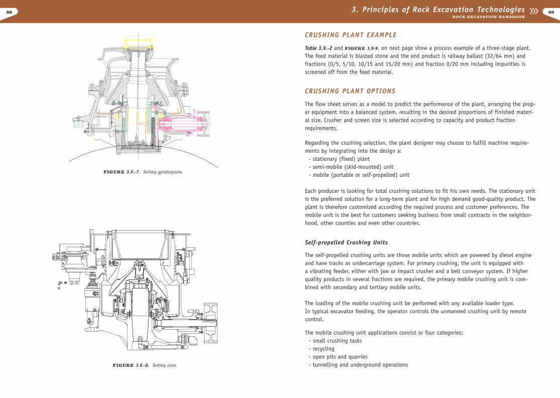
FIGURE 3.9.-7. Tertiary gyratorycone.
90 913. Principles of Rock Excavation TechnologiesROCK EXCAVATION HANDBOOK
Table 3.9.-2. Process example of a three stage plant.
Crushing Part Task/explanation Remarkstage/part number
1 Feed material Blasted rock Gradation 0/750
I/2 Feeder Adjusts primary crushing unit capacity and screens off material smaller than the crusher setting
I/4 Jaw crusher Crushes material In primary crushing unit,down to suitable capacity is at maximumsize for following which requires reserve crushing stages capacity
I/3 Screen Screens off waste If waste material is not material from material screened off at this stage,run through grizzly it enters end product
5 End product Waste material Can normally be sold as 0/20 filling material
I/6 Inter- Separates primary Allows different capacitiesmediate stage from latter at stages and operation of stockpile part of process stages to be separated
II/8 Secondary Crushes product to Closed circuit improvescrusher a suitable size for end-product quality and
tertiary crusher and gives flexibility to processproduces railway ballast
II/9 Screen Screens off railway ballast. Oversize is carried back to secondary crusher
10 End Railway ballast Standards vary by product 32/64 mm country
III/11 Screen Screens off feed material for fine crusher
III/12 Interm. Evens capacity and keeps hopper fine crusher always full
of material
III/13 Fine crusher Guarantees end product distribution and cubicity
III/14 Screen Carries oversize back to fine crusher and screens end product
III/15 Screen End product screen
16-19 End Example of high-qualityproducts end products, standards
vary by country
FIGURE 3.9.-9. Crushing process example of a three stage plant.
9392 3. Principles of Rock Excavation TechnologiesROCK EXCAVATION HANDBOOK
Small crushing tasks
The selfpropelled crushing units provide an ideal solution for exploiting small, scatteredsite rock, gravel and waste rock deposits. Small units are easily transported on a standardlow-bed trailer on public roads to the worksite. Minimum time iswasted as the selfpropelledand selfcontained unit is within a few minutes ready to do the crushing task.
Selfpropelled crushing units are typically found on construction sites. Stone that has beblasted from the base can be rushed and used on-site. This kind of set up is also usedonroad construction sites.
The main benefits of using mobile crushing units in small crushing tasks are:- fast and easy access from site to site- fast set up- full on-site mobility- easy material loading- decreased requirement for haulage equipment
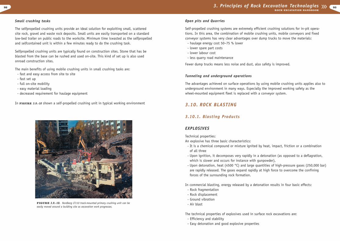
In FIGURE 3.9.-10 shown a self-propelled crushing unit in typical working environment
Open pits and Quarries
Self-propelled crushing systems are extremely efficient crushing solutions for in-pit opera-tions. In this area, the combination of mobile crushing units, mobile conveyors and fixedconveyor systems has very clear advantages over dump trucks to move the materials:
- haulage energy cost 50–75 % lower - lower spare part costs - lower labour cost - less quarry road maintenance
Fewer dump trucks means less noise and dust, also safety is improved.
Tunneling and underground operations
The advantages achieved on surface operations by using mobile crushing units applies also tounderground environment in many ways. Especially the improved working safety as thewheel-mounted equipment fleet is replaced with a conveyor system.
3.10. ROCK BLASTING
3.10.1. Blasting Products
EXPLOSIVES
Technical properties:An explosive has three basic characteristics:
- It is a chemical compound or mixture ignited by heat, impact, friction or a combination of all three
- Upon ignition, it decomposes very rapidly in a detonation (as opposed to a deflagration, which is slower and occurs for instance with gunpowder),
- Upon detonation, heat (4500 °C) and large quantities of high-pressure gases (250,000 bar)are rapidly released. The gases expand rapidly at high force to overcome the confiningforces of the surrounding rock formation.
In commercial blasting, energy released by a detonation results in four basic effects:- Rock fragmentation- Rock displacement- Ground vibration- Air blast
The technical properties of explosives used in surface rock excavations are:- Efficiency and stability- Easy detonation and good explosive properties
FIGURE 3.9.-10. Nordberg LT110 track-mounted primary crushing unit can beeasily moved around a building site as excavation work progresses.
94
Temperature changes affect the velocity depending on the explosive type. Typically, explo-sives that contain little or no liquid are relatively unaffected at the normal low temperatureexperienced in commercial blasting.
Sufficient priming ensures that explosives reach maximum velocity as quickly as possible.Insufficient priming results in the failure of the explosive to detonate, in slow build-up tofinal velocity and in a lower order detonation.
Explosion propagation is required to continue the reaction through the total charge, or theability to ignite the next charge through a distance in free air. Propagation increases in theblasthole. Increasing diameter also increases explosion propagation.
Some types of explosives are so sensitive that they propagate between blastholes over con-siderable distances. This depends on the type of material to be blasted, the explosive, thesize of the charge, the distance between blastholes and other factors such as the presence ofwater. In most situations, it is important that individual charges do not propagate, but deto-nate independently with a predetermined delay.
The specific gas volume is the amount of gas created by one kilogram of explosives undernormal conditions (0°C and 760 mm Hg) expressed in liters/kg. The explosion heat is theamount of energy released upon detonation. It is usually expressed in kJ/kg. The effect ofthe gas pressure wave depends on the amount of heat and gas volume created by the explo-sion. In heat expansion 30 - 40% of the heat is converted into mechanical work.
The combined effect of specific gas volume and explosion heat is that the heat releasedactually expands the gases produced. The greater the gas volume and the hotter the gases,the more effective the explosive is.
953. Principles of Rock Excavation TechnologiesROCK EXCAVATION HANDBOOK
- Safe handling- Good film characteristics - Non-toxic- Water resistance and good storage properties- Environmental properties- Resistance to freezing- Oxygen balance- Shelf life
Efficiency and stability
An explosive’s efficiency and stability determine, how explosive should be used in a blastingproject. The other characteristics are more or less common to all explosives. When comparing the efficiency of different explosives, the following technical characteristics should be takeninto consideration:
- Velocity of detonation (VOD)- Explosion propagation (sensitivity)- Specific gas volume- Explosion heat- Strength per unit weight- Charging density (density of explosive in the hole)- Strength per unit volume
The detonation velocity of an explosive is the meter-per-second speed at which the detona-tion wave travels through the explosive charge. Many factors affect detonation velocity suchas product type, diameter, confinement, temperature and degree of priming.
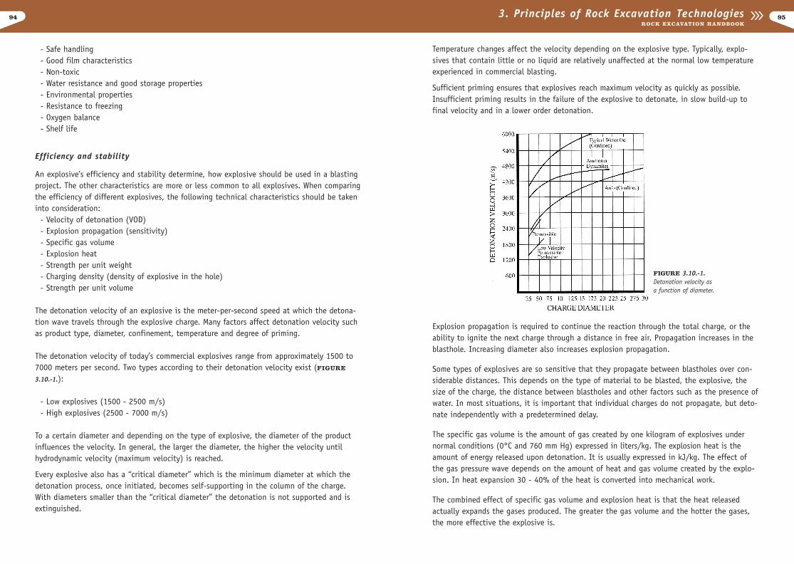
The detonation velocity of today’s commercial explosives range from approximately 1500 to7000 meters per second. Two types according to their detonation velocity exist (FIGURE
3.10.-1.):
- Low explosives (1500 - 2500 m/s)- High explosives (2500 - 7000 m/s)
To a certain diameter and depending on the type of explosive, the diameter of the productinfluences the velocity. In general, the larger the diameter, the higher the velocity untilhydrodynamic velocity (maximum velocity) is reached.
Every explosive also has a “critical diameter” which is the minimum diameter at which thedetonation process, once initiated, becomes self-supporting in the column of the charge.With diameters smaller than the “critical diameter” the detonation is not supported and isextinguished.
FIGURE 3.10.-1.Detonation velocity asa function of diameter.
96
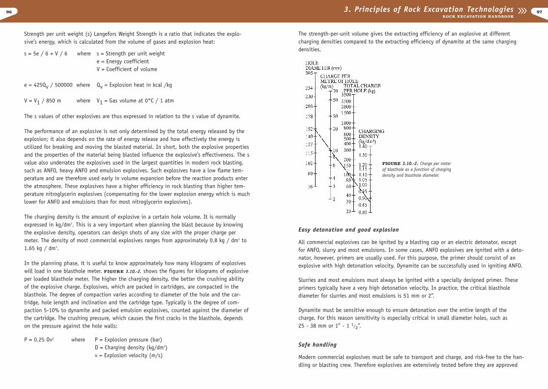
The strength-per-unit volume gives the extracting efficiency of an explosive at differentcharging densities compared to the extracting efficiency of dynamite at the same chargingdensities.
Easy detonation and good explosion
All commercial explosives can be ignited by a blasting cap or an electric detonator, exceptfor ANFO, slurry and most emulsions. In some cases, ANFO explosives are ignited with a deto-nator, however, primers are usually used. For this purpose, the primer should consist of anexplosive with high detonation velocity. Dynamite can be successfully used in igniting ANFO.
Slurries and most emulsions must always be ignited with a specially designed primer. Theseprimers typically have a very high detonation velocity. In practice, the critical blasthole diameter for slurries and most emulsions is 51 mm or 2”.
Dynamite must be sensitive enough to ensure detonation over the entire length of thecharge. For this reason sensitivity is especially critical in small diameter holes, such as25 - 38 mm or 1” - 1 1/2”.
Safe handling
Modern commercial explosives must be safe to transport and charge, and risk-free to the han-dling or blasting crew. Therefore explosives are extensively tested before they are approved
973. Principles of Rock Excavation TechnologiesROCK EXCAVATION HANDBOOK
Strength per unit weight (s) Langefors Weight Strength is a ratio that indicates the explo-sive’s energy, which is calculated from the volume of gases and explosion heat:
s = 5e / 6 + V / 6 where s = Strength per unit weighte = Energy coefficientV = Coefficient of volume
e = 425Qv / 500000 where Qv = Explosion heat in kcal /kg
V = V1 / 850 m where V1 = Gas volume at 0°C / 1 atm
The s values of other explosives are thus expressed in relation to the s value of dynamite.
The performance of an explosive is not only determined by the total energy released by theexplosion; it also depends on the rate of energy release and how effectively the energy isutilized for breaking and moving the blasted material. In short, both the explosive propertiesand the properties of the material being blasted influence the explosive’s effectiveness. The svalue also underrates the explosives used in the largest quantities in modern rock blasting,such as ANFO, heavy ANFO and emulsion explosives. Such explosives have a low flame tem-perature and are therefore used early in volume expansion before the reaction products enterthe atmosphere. These explosives have a higher efficiency in rock blasting than higher tem-perature nitroglycerin explosives (compensating for the lower explosion energy which is muchlower for ANFO and emulsions than for most nitroglycerin explosives).
The charging density is the amount of explosive in a certain hole volume. It is normallyexpressed in kg/dm3. This is a very important when planning the blast because by knowingthe explosive density, operators can design shots of any size with the proper charge permeter. The density of most commercial explosives ranges from approximately 0.8 kg / dm3 to1.65 kg / dm3.
In the planning phase, it is useful to know approximately how many kilograms of explosiveswill load in one blasthole meter. FIGURE 3.10.-2. shows the figures for kilograms of explosiveper loaded blasthole meter. The higher the charging density, the better the crushing abilityof the explosive charge. Explosives, which are packed in cartridges, are compacted in theblasthole. The degree of compaction varies according to diameter of the hole and the car-tridge, hole length and inclination and the cartridge type. Typically is the degree of com-paction 5-10% to dynamite and packed emulsion explosives, counted against the diameter ofthe cartridge. The crushing pressure, which causes the first cracks in the blasthole, dependson the pressure against the hole walls:
P = 0.25 Dv2 where P = Explosion pressure (bar)D = Charging density (kg/dm3)v = Explosion velocity (m/s)
FIGURE 3.10.-2. Charge per meter of blasthole as a function of charging density and blasthole diameter.

98
(1.293 kg/m3). However, it is extremely unlikely that separation could occur in a mine ortunnel. If inhaled, the gas is extremely toxic. Carbon monoxide´s affinity for blood hemoglo-bin is considerably higher than that of oxygen. Asphyxiation can occur if the CO concentra-tion is high enough.
Nitric oxide (NO) is also colorless and highly toxic if inhaled. NO is a strong irritant to skinand mucous membranes. Through oxidation, it forms nitrogen dioxide (NO2). NO2 is a red-dish-brown gas and inhalation is fatal at high concentrations. If the fume cloud has NO2concentrations exceeding 30 ppm, the color is orange/red when observed against a whitelight source.
Table 3.10.-1. reviews threshold values of exposure concentrations established in Sweden bythe Labour Safety Board [Arbetarsskylddsstyrelsen, 1974] and in the USA [ACGIM, 1970].Investigations made by G. Persson showed that 4 - 8% of the fumes from tunnel rounds aretrapped in the muck pile for 1 hour. It is possible to evaluate 25 - 50% of trapped gas.
Fumes from nitroglycerin explosives contain small amounts of nitroglycerin and/or nitroglycolwhich dilate blood vessels, cause headaches and lowers blood pressure. Skin contact with theexplosive is perhaps the most important form of exposure. Inhalation of vapors during charg-ing or inhalation of the vapors from dead or partially reacted explosives after the blast causeheadaches.
In the USA, the IME has established the Fume Classification Standard, which is based on thevolume of poisonous gas emitted by a 1 1/4 * 8-inch cartridge when detonated under stan-dardized conditions. High explosives are classified under this standard as follows:
Class 1: 0 - 0.16 ft3 per cartridgeClass 2: 0.16 - 0.33 ft3 per cartridgeClass 3: 0.33 - 0.67 ft3 per cartridge
Only those explosives meeting the requirements of Class 1 may be used in undergroundmines. For coal mines, the MSHA has determined that the volume of poisonous gases pro-duced must not exceed 71 liters per 454 gm of permissible explosive (2.5 ft3 / lb). In anyevent, good ventilation is necessary. Dispersing the fumes from a blasted heading beforeminers return to work is a vital precaution.
It is possible to considerably reduce the amount of toxic fumes formed in tunneling if thefollowing recommendations and procedures are adhered to during the planning and charging of the blast:
- Use an oxygen-balanced explosive with good fume characteristics.- Use alignment devices when drilling so that most holes
are slanted slightly upward, therefore, preventing water fromaccumulating in the drillhole, contaminating the explosive andaffecting its detonating performance.
993. Principles of Rock Excavation TechnologiesROCK EXCAVATION HANDBOOK
by the authorities. A basic test for commercial explosives is the stress test, in which aweight is permitted to fall onto the explosive from a certain height. This test determines thesensitivity of the explosive to impacts.
Explosives are also subjected to tests where their sensitivity to friction and shooting isdetermined. Safe handling often depends on the insensitivity of an explosive when it is sub-jected to drilling. In practice, for one reason or another, certain parts of bench blasts oreven complete blasts do not detonate when fired. Additional holes must be drilled and drillbits sometimes punch the explosive charges in the rock. Although modern explosives are rel-atively insensitive to shocks, it is not possible to be 100% sure of the safety of drillingthrough charges.
Toxic fumes
Some fumes created by detonating explosives and blasting agents may contain reaction prod-ucts that pose health or environmental hazards. The majority of reaction products from deto-nating oxygen-balanced explosives are harmless. Small amounts of toxic reaction productsare, however, formed as a result of deviations from oxygen balance, incomplete reactions orsecondary reactions with the atmospheric air.
The amount of non-ideal detonation products formed depends on factors such as explosivecomposition and homogeneity, effect of water on the explosive after being loaded into a wetdrillhole (water resistance), velocity of detonation, charge diameter, loading density, initia-tion type, cartridge wrapper type and most importantly explosive confinement. Before andduring detonation, additional reactions can also occur between the explosive and the sur-rounding rock such as when the rock contains sulfide or other reactive components.
Table 3.10.-1. Threshold values for toxic fumes.
Fume Finland Sweden USA(8 hr working day) (Threshold values, ppm)
CO 50 25 50NOx 20NO2 3 2 5NO 25 25NH3 50CO2 5000 5000SO2 2H2S 10
Most commonly, only carbon monoxide (CO) and nitrogen oxides (NO and NO2) reach a highenough concentration so that it is dangerous to be exposed to the fumes after a blast.Carbon monoxide (CO) is a colorless, odorless gas formed by the incomplete combustion oforganic material. Its density is slightly lower (1.25 kg/m3) than atmospheric air
100
The storage properties of commercial explosives define the period of time for which they canbe stored without effecting safety, reliability, and performance. Although shelf life hasimproved, it is still important to avoid prolonged storage periods.
Plastic explosives should not be stored in or subjected to high temperatures since they cansoften and the explosive’s salt substance can penetrate the paper wrapping around the car-tridge. If this happens, the cartridges become deformed and difficult to use. Powder-type car-tridge explosives are usually more sensitive to moisture in storage. In high humidity, theexplosive’s salt can form deposits on the cartridge which harden. Aging does not apply inthis case.
Mixed explosives can in certain cases separate, in which their characteristics change com-pletely. Factory-manufactured explosives are normally produced in such a way that this doesnot occur.It is important to keep explosive stores clean and dry. Storage should be plannedin such a way to ensure fast usage.
Types of explosives
An extensive range of different types and grades of explosives is made to suit all blastingrequirements. A breakdown of blasting explosives is presented in Table 3.10.-2.
Table 3.10.-2. Breakdown of blasting explosives.
Explosive Explosivebase type Features
Nitro- Dynamite A highly adaptable cartridge explosive currently widely used becauseglycerin Gelatin of its excellent performance in smaller diameter holes.
Ammonium ANFO A low-cost, high-power, extremely safe, liquid explosive made fromnitrate porous prilled ammonium nitrate and fuel oil.
Poor water resistance.
Water Slurry Essentially, ANFO which becomes water resistant by adding water andOil Emulsion forming either a gel (water gel), or creating astable oil/water emulsion
and ANFO called heavy ANFO. Available in package or liquid form.
Dynamite and gelatins
Over the years, ammonium nitrate has become more important in dynamite, replacing a largeportion of nitroglycerin. The same is true with the dynamite currently used in the Nordiccountries.
1013. Principles of Rock Excavation TechnologiesROCK EXCAVATION HANDBOOK
- Do not use detonating cords in ANFO-loaded small-diameter holes as it might not initiate the ANFO to complete reaction, resulting in large amounts of toxic fumes. The cord itself is strongly oxygen deficient, and by itself generates approximately 3 l CO per meter length of cord.
- Leave an unloaded (or preferably stemmed) hole length equal to 10 times the hole diameter at the mouth of the hole in tunneling and drifting. Filling explosives all the way to the collar does not contribute significantly to the breakage process, but it produces a lot of toxic fumes.
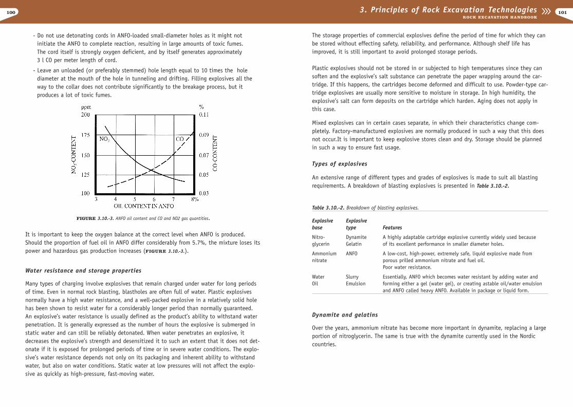
FIGURE 3.10.-3. ANFO oil content and CO and NO2 gas quantities.
It is important to keep the oxygen balance at the correct level when ANFO is produced.Should the proportion of fuel oil in ANFO differ considerably from 5.7%, the mixture loses itspower and hazardous gas production increases (FIGURE 3.10.-3.).
Water resistance and storage properties
Many types of charging involve explosives that remain charged under water for long periodsof time. Even in normal rock blasting, blastholes are often full of water. Plastic explosivesnormally have a high water resistance, and a well-packed explosive in a relatively solid holehas been shown to resist water for a considerably longer period than normally guaranteed.An explosive’s water resistance is usually defined as the product’s ability to withstand waterpenetration. It is generally expressed as the number of hours the explosive is submerged instatic water and can still be reliably detonated. When water penetrates an explosive, itdecreases the explosive’s strength and desensitized it to such an extent that it does not det-onate if it is exposed for prolonged periods of time or in severe water conditions. The explo-sive’s water resistance depends not only on its packaging and inherent ability to withstandwater, but also on water conditions. Static water at low pressures will not affect the explo-sive as quickly as high-pressure, fast-moving water.

102
diametrically (axial priming) and as the ANFO will not reach a stable velocity of detonation(2000 to 4400 m / s), the chemical reaction will be incomplete.
Reduced ANFO
Different methods of mixing ANFO with inert material has been tried, but today the mostcommonly used material for reduction is expanded polystyrene spheres. Due to varying densi-ty, ANFO and the polystyrene spheres tend to separate. However, a new charging techniquedeveloped by Dyno Industries Norway solved this problem. The technique is similar to thatused for concrete grouting. ANFO and the reduction material are stored in separate contain-ers but then mixed together in a charging hose through which the mixture is blown into theblasthole. Two containers are needed for charging by this method. However, it is most practi-cal and least bulky when one container is placed inside the other.
Heavy ANFO
Heavy ANFO is a mixture of ANFO and emulsion explosive. It is becoming more popularbecause it is often as effective as pure emulsions and considerably cheaper. Prilled ANFOconsists of spheres or prills of sensitized ammonium nitrate infused with fuel oil. Maximumdensity occurs when the prills are in mutual contact, which leaves voids that, in heavy ANFO,are filled with a base emulsion, cold pumpable explosive with sufficient viscosity and stabili-ty. The sensitizing mechanism for emulsion explosives is provided by voids. In heavy ANFO,the prills act as voids or density adjusters and the emulsion fills the gaps. The proportions ofthe constituents can be varied to alter sensitivity, energy and water resistance.
With the normal range of compositions, density increases with emulsion content up to a max-imum of 1.3 kg / dm3. The charge’s sensitivity is opposite to both the density and emulsioncontent.
Both energy and sensitivity peak at a density of approximately 1.3. Adding microballoons tothe base emulsion enhances sensitivity, energy and water resistance, however it also increas-es the cost. Water resistance is also dependent upon emulsion content and quality, sensitivi-ty, degree of blending and particularly storage time during and after loading.
Slurries
Slurries are specially designed for large-hole blasting and wet conditions. Slurries are notnormally cap-insensitive and therefore must be initiated with a primer. Slurries are waterresistant and are either pumped straight into the hole or applied in plastic bags.
Slurry contains ammonium nitrate, and often aluminum, water and substances to keep theexplosive homo-geneous. The properties of any individual composition depend on the typeand proportions of various solid ingredients. Because it is denser than water
1033. Principles of Rock Excavation TechnologiesROCK EXCAVATION HANDBOOK
There are three basic types of dynamite: granular, semi-gelatin and gelatin. Gelatin and semi-gelatin dynamite contain nitrocotton, a cellulose nitrate that combines with nitroglycerin toform a cohesive gel. The viscosity of this product depends on the percentage of nitrocotton.Granular dynamite, on the other hand, does not contain nitrocotton and has a grainy texture.
Usually, the higher the nitroglycerin percentage, the more water resistant the explosivebecomes. Dynamite issued in bottom charges. Low-percentage dynamite is often used in col-umn charges. These explosives are often used in small diameter blastholes at constructionblasting sites. Paraffin paper covers are used for small-cartridge explosives (d ( 40 mm) andplastic bags for bigger cartridges. In certain smooth blasting projects, pre-splitting and gen-erally for tasks where a very light charge is necessary, special dynamite can be used as aready-made tube charge.
Aniitti
Aniitti is a non-nitroglycerin, ammonium-nitrate explosive, which among other things con-tains trotyl (TNT) and aluminum. Aniitti in cartridges is used especially in drifting. Aniitticontained in plastic bags is mostly used in large holes as a column charge and in clearing.
Original ANFO
ANFO is a mixture of ammonium nitrate and fuel oil (5.7%), in which ammonium nitrate actsas the oxidizer and the fuel oil acts as the fuel. ANFO offers great economy and safety inmodern blasting applications. It is generally one-third to one-half cheaper than nitroglycerinexplosives and it is considerably safer to handle because it is non-sensitive. In many types ofblasting, ANFO produces better fragmentation due to its high gas producing properties.
ANFO is among the best explosive for blasting dry holes in excess of 51 mm (2”) in holediameter, which are conductive to breakage by gaseous expansion. However, it is not so goodin small-diameter blastholes and conditions that require very high detonating velocities.
The main disadvantage of ANFO is that it is not water resistant: if it gets wet, it no longer detonates. Some ANFO products can be charged in wet holes, ifthe water is removed before charging. Leaving ANFO in a loaded hole for an extended periodof time should therefore be avoided. Additionally, ANFO can not be detonated by a normaldetonator.
Detonation velocity changes with the diameter of the blasthole and reaches the highestvelocity of 4400 m / s in a 250 mm blasthole. Likewise, detonation velocity decreases withthe diameter of the blasthole. When the diameter is less than 25 mm, the detonation will notbe stable. ANFO is most suitable in middle and large-diameter blastholes (75 to 250 mm)under dry conditions.Initiation of ANFO should not be made with detonating cord in smalland medium-sized blastholes (25 to 100 mm). The detonating cord will initiate the ANFO
104
By using different percentages of microballoons and aluminum, a wide range of emulsionexplosives can be manufactured.
The cap sensitive range is intended for small and medium-diameter blastholes and is deliveredin paper shells and plastic bags. The non-cap sensitive range is intended for medium andlarge-diameter blastholes in bench blasting, and is delivered in plastic hoses.
Pumpable bulk emulsions, which are economical alternatives to ANFO in quarrying, miningand tunneling are also very interesting. Pumpable bulk emulsifying and mixing process cantake place either at the bulk emulsion station or on the mixing/loading truck. When theexplosive is prepared at the station, the explosive truck acts as a simple transport and load-ing unit for the explosives. Alternatively, the truck can be used as a mixing and loading unit.In the latter case, explosive preparation will take place at the worksite, allowing continuousblasthole loading with precise amounts of various mixtures.
This system enables explosives to be produced economically. Loading is accurate, and bulkemulsion can easily be pumped at speeds of up to 200 kilograms per minute. A furtheradvantage is that it can even be pumped into holes containing water. The substance canadditionally remain unchanged for months even under severe conditions.
INITIATION OF EXPLOSIVES
General
Today’s common surface blasting systems for initiating explosives are:
- Firing cord and blasting caps- Detonating cord and detonating delays- Electric blasting caps (detonators)- Shock wave conduction to detonation caps - Electro-magnetic firing methods- Magnadet system- Electronic detonators
1053. Principles of Rock Excavation TechnologiesROCK EXCAVATION HANDBOOK
(1.4 - 1.6 kg/dm3), the slurry sinks to the bottom of a wet blasthole. The detonation velocityof slurries ranges from 3,400 m/s to 5,500 m/s.
Emulsion explosives
Emulsion explosives are grabbing more market share due to their safe and versatile features.Emulsions are so-called two-phase products. The dispersed phase is dissimulated throughouta continuous phase. Explosive emulsions consist of a mixture of fuel and oxidant compo-nents. The oxidizers are primarily nitrates and the fuels mostly mineral or organic hydrocar-bon derivations. The oxidant / fuel ratio is approximately 10:1.
When inspected with an electron microscopy, the structure of the emulsion exhibits a polyhe-dral shape with each droplet covered by a film of the fuel phase.
The detonation reaction occurs at the boundaries between the two phases. Emulsions provideincreased explosive efficiency because both phases are liquid and the dispersed nitrate solu-tion droplets are smaller than other conventional explosives; 0.001 mm as opposed to0.2 mm. They are tightly packed within the fuel phase and provide increased surface contact,effectively enhancing the reaction. The strength of the reaction can therefore be altered bychanging the degree of fuel and oxidant. The water content of the nitrate is also reduced byusing super-saturated solutions.
Increased efficiency is reflected in the detonation velocity, 5000 - 6000 m/s for emulsionscompared with approximately 3200 m/s for ANFO and 3300 m/s for slurry. This high-velocitydetonation is one of the major advantages of emulsions as it provides high-shock energy,which is a significant factor in hard rocks.
Unlike other explosives, emulsions do not use chemical sensitizers. Instead, voids in the emul-sion fulfills this requirement. The number of voids determines the density of the mixture.
The viscosity and density of any emulsion is determined largely by the physical characteris-tics of the organic fuel phase, which can vary from liquid fuel oil to viscous waxes. Unlikeslurries, emulsions can not be gelled or cross-linked, their structure being characteristic ofthe nitrate and continuous fuel phase.
Bulk emulsion explosives are especially suited for open-pit mining because of their waterresistant properties and chemical stability.
Emulsions are structurally distinct from slurries because they do not contain thickeners orgelling compounds, and require mixing at approximately 80°C. Also they do not contain struc-tural additives, the phases must cool by 30° - 50°C before the fuel phase becomes semi-rigid.
106
No. 8 strengths. For normal initiation with most explosives, the standard No. 6 cap is suffi-ciently strong. No. 8 provides additional initiation power.
The flame is conveyed through the safety fuse at a uniform rate for igniting the blasting cap.The safety fuse core consists of a black powder train, tightly wrapped with covering tape,textiles and waterproofing material such as asphalt and plastics.
In addition to its ability to initiate black powder and, together with blasting caps, initiatehigh explosives, firing cord provides a burning speed within reasonable tolerances of approxi-mately 1 meter per 100 seconds (1 foot per 30 seconds).
Initiation by detonating cord
Detonating cord is a flexible tube containing a center core of high-velocity, cap-sensitiveexplosive that is used to
- Detonate other high explosives which it comes into contact with- Transmit a detonation wave from detonating cord to detonating cord or to a
non-electric cap
1073. Principles of Rock Excavation TechnologiesROCK EXCAVATION HANDBOOK
Firing cord and blasting caps (detonators)
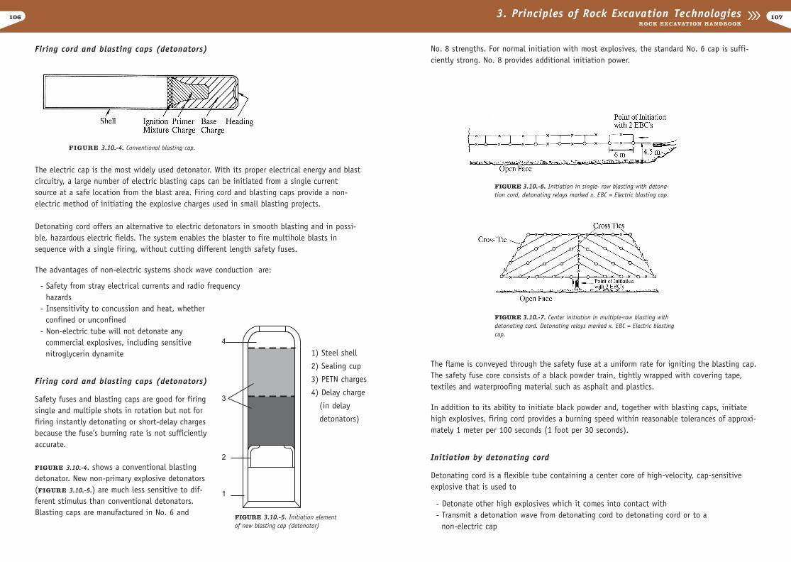
FIGURE 3.10.-4. Conventional blasting cap.
The electric cap is the most widely used detonator. With its proper electrical energy and blastcircuitry, a large number of electric blasting caps can be initiated from a single currentsource at a safe location from the blast area. Firing cord and blasting caps provide a non-electric method of initiating the explosive charges used in small blasting projects.
Detonating cord offers an alternative to electric detonators in smooth blasting and in possi-ble, hazardous electric fields. The system enables the blaster to fire multihole blasts insequence with a single firing, without cutting different length safety fuses.
The advantages of non-electric systems shock wave conduction are:
- Safety from stray electrical currents and radio frequency hazards
- Insensitivity to concussion and heat, whether confined or unconfined
- Non-electric tube will not detonate any commercial explosives, including sensitive nitroglycerin dynamite
Firing cord and blasting caps (detonators)
Safety fuses and blasting caps are good for firingsingle and multiple shots in rotation but not forfiring instantly detonating or short-delay chargesbecause the fuse’s burning rate is not sufficientlyaccurate.
FIGURE 3.10.-4. shows a conventional blastingdetonator. New non-primary explosive detonators(FIGURE 3.10.-5.) are much less sensitive to dif-ferent stimulus than conventional detonators.Blasting caps are manufactured in No. 6 and
FIGURE 3.10.-6. Initiation in single- row blasting with detona-tion cord, detonating relays marked x. EBC = Electric blasting cap.
FIGURE 3.10.-7. Center initiation in multiple-row blasting withdetonating cord. Detonating relays marked x. EBC = Electric blastingcap.
FIGURE 3.10.-5. Initiation elementof new blasting cap (detonator)
1) Steel shell
2) Sealing cup
3) PETN charges
4) Delay charge
(in delay
detonators)
108
FIGURE 3.10.-8. shows an arrangement for a multiple-row blast via detonating relays on eachhole. The holes are fired in a V shape across the cut. A maximum of four holes can be firedat any time.
The explosive’s effect will be somewhat reduced when detonating with cord because theexplosion does not reach maximum velocity. An explosive’s duration velocity increases as thedetonation advances from the initiation point. When detonating cord is used, detonationoccurs at all points: in this case there is no increase in the detonation velocity. When deto-nating cord is used as a downline to carry the initiating impulse into a blasthole throughcap-insensitive explosives such as ANFO, to a cap and primer, it burns some of the explosiveit passes through, therefore diminishing the effective volume of the charge.
Detonating cord can disrupt the explosive column especially in smaller diameter blastholes,which affects the efficiency of the explosives involved. Detonating cord trunklines also con-tribute to noise associated with blasting in residential areas which also creates problems.One solution is to use lower-energy detonating cord. Detonating cord does have advantages;it is the safest, simplest and most reliable blast initiating system ever developed.
Because detonating cord initiates all capsensitive explosives loaded alongside the cord in theblasthole, bottom priming and delayed deck charging methods can not be used. Initiationmust be either from the top of the explosive column or from spaced boosters. With ANFO andcap-insensitive slurries, energy transmitted through medium to high-strength detonatingcord, for example with a 6 - 12 g/m PETN core, is sufficient to desensitize the ANFO, slurriesor emulsions via a partial detonation effect, particularly in holes with diameters smaller than102 mm (4”).
1093. Principles of Rock Excavation TechnologiesROCK EXCAVATION HANDBOOK
The core is covered in reinforced woven waterproof plastic. Detonation cord is not sensitiveto ordinary shock or friction. The amount of high explosives in detonating cord varies from1 to 1,300 grains of PETN per meter. The most commonly used grades contain 80 - 160grains/m. By contrast to the 0,01 m/s burning rate for safety fuse, detonating cord deto-nates at approximately 6,000 - 8,000 m/s and has the effect of a blasting cap along itsentire length.
Detonating cord is often used in large quarries and mines to initiate higher explosives. Todayit is also common in smooth blasting. When detonating cord is used in places where there isdanger of unpremeditated initiation of electric detonators, it is initiated by firing cord andblasting cap No. 8.
Due to its high detonation velocity, detonating cord together with light charges is used insmooth blasting. Multiple-charge explosives can be fired without significant delay betweencharges, by detonating from the top of the blasthole. In addition, the explosion’s propaga-tion direction can be selected according to the rock formation.
When blasting with detonating cord, detonating relays are used that consist of delayed unitsto provide convenient short-delay firing intervals (5 - 400 ms). Each relay consists of twodelay detonators assembled in an aluminum sleeve which can be inserted in the detonatingcord wherever a delay interval is required (FIGURES 3.10.-6. and 3.10.-7.).
Connecting a detonation cord:
- Keep each connection at a right angle. Plastic connectors are convenient and reliable- Distance between parallel cords should be no less than 0.2 m- Distance between relay connector and parallel cord should always be pointed in the
direction of the detonating cord detonation
A simple delay arrangement is to use separate delay relays for each main line of detonatingcord by connecting the individual holes in a row. This system achieves successive displace-ment from each row toward the free face.
FIGURE 3.10.-8. Short-delay blasting using detonating relays
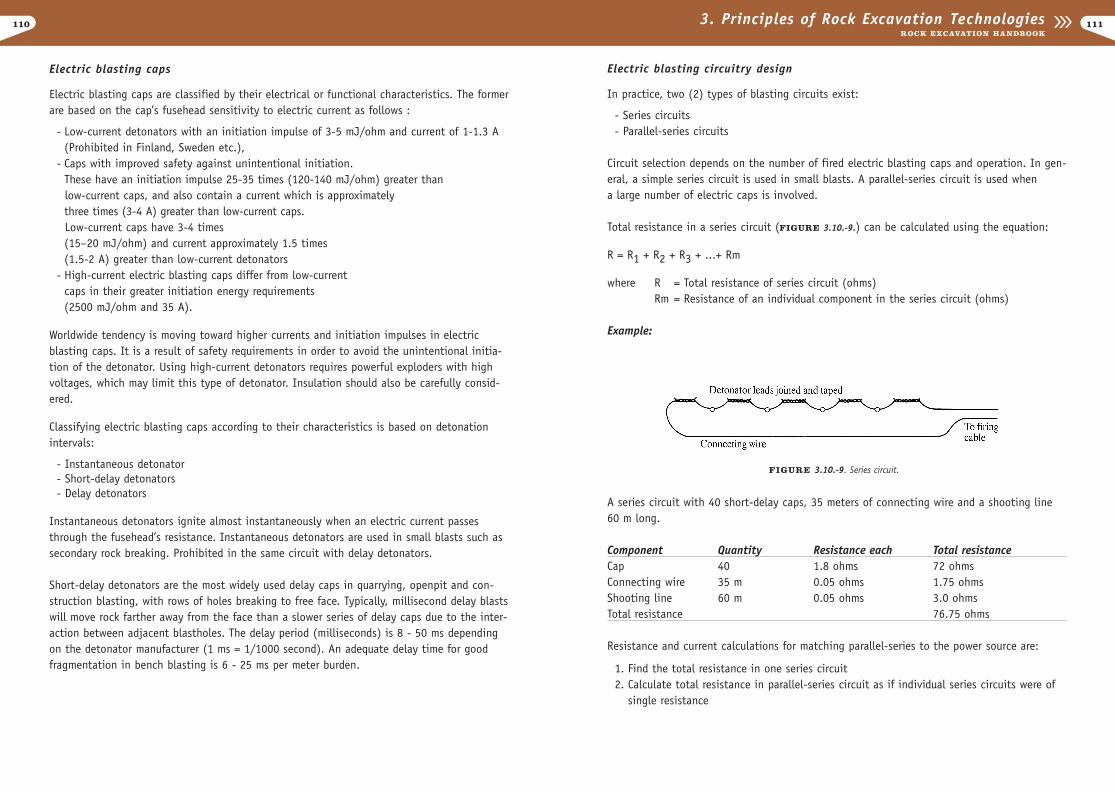
110
Electric blasting circuitry design
In practice, two (2) types of blasting circuits exist:
- Series circuits- Parallel-series circuits
Circuit selection depends on the number of fired electric blasting caps and operation. In gen-eral, a simple series circuit is used in small blasts. A parallel-series circuit is used when a large number of electric caps is involved.
Total resistance in a series circuit (FIGURE 3.10.-9.) can be calculated using the equation:
R = R1 + R2 + R3 + ...+ Rm
where R = Total resistance of series circuit (ohms)Rm = Resistance of an individual component in the series circuit (ohms)
Example:
A series circuit with 40 short-delay caps, 35 meters of connecting wire and a shooting line60 m long.
Component Quantity Resistance each Total resistanceCap 40 1.8 ohms 72 ohmsConnecting wire 35 m 0.05 ohms 1.75 ohmsShooting line 60 m 0.05 ohms 3.0 ohmsTotal resistance 76.75 ohms
Resistance and current calculations for matching parallel-series to the power source are:
1. Find the total resistance in one series circuit2. Calculate total resistance in parallel-series circuit as if individual series circuits were of
single resistance
1113. Principles of Rock Excavation TechnologiesROCK EXCAVATION HANDBOOK
Electric blasting caps
Electric blasting caps are classified by their electrical or functional characteristics. The formerare based on the cap’s fusehead sensitivity to electric current as follows :
- Low-current detonators with an initiation impulse of 3-5 mJ/ohm and current of 1-1.3 A (Prohibited in Finland, Sweden etc.),
- Caps with improved safety against unintentional initiation. These have an initiation impulse 25-35 times (120-140 mJ/ohm) greater than low-current caps, and also contain a current which is approximately three times (3-4 A) greater than low-current caps.Low-current caps have 3-4 times (15–20 mJ/ohm) and current approximately 1.5 times (1.5-2 A) greater than low-current detonators
- High-current electric blasting caps differ from low-current caps in their greater initiation energy requirements (2500 mJ/ohm and 35 A).
Worldwide tendency is moving toward higher currents and initiation impulses in electricblasting caps. It is a result of safety requirements in order to avoid the unintentional initia-tion of the detonator. Using high-current detonators requires powerful exploders with highvoltages, which may limit this type of detonator. Insulation should also be carefully consid-ered.
Classifying electric blasting caps according to their characteristics is based on detonationintervals:
- Instantaneous detonator - Short-delay detonators - Delay detonators
Instantaneous detonators ignite almost instantaneously when an electric current passesthrough the fusehead’s resistance. Instantaneous detonators are used in small blasts such as secondary rock breaking. Prohibited in the same circuit with delay detonators.
Short-delay detonators are the most widely used delay caps in quarrying, openpit and con-struction blasting, with rows of holes breaking to free face. Typically, millisecond delay blastswill move rock farther away from the face than a slower series of delay caps due to the inter-action between adjacent blastholes. The delay period (milliseconds) is 8 - 50 ms dependingon the detonator manufacturer (1 ms = 1/1000 second). An adequate delay time for goodfragmentation in bench blasting is 6 - 25 ms per meter burden.
FIGURE 3.10.-9. Series circuit.
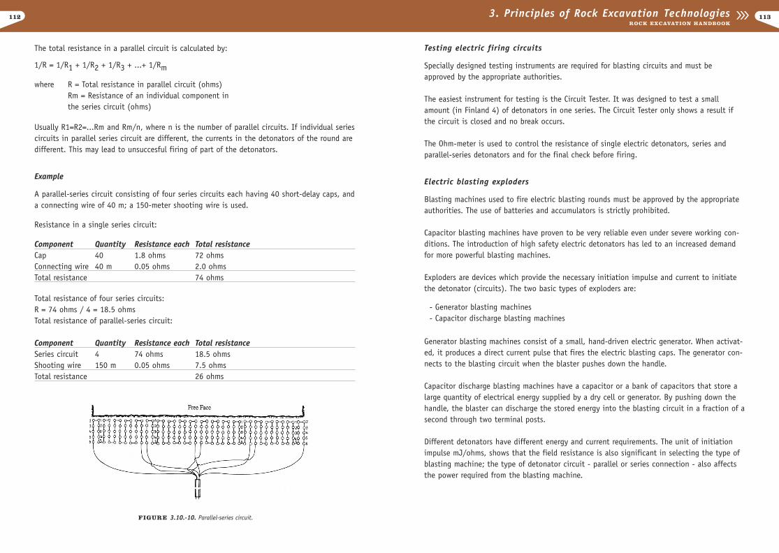
112
Testing electric firing circuits
Specially designed testing instruments are required for blasting circuits and must beapproved by the appropriate authorities.
The easiest instrument for testing is the Circuit Tester. It was designed to test a smallamount (in Finland 4) of detonators in one series. The Circuit Tester only shows a result ifthe circuit is closed and no break occurs.
The Ohm-meter is used to control the resistance of single electric detonators, series andparallel-series detonators and for the final check before firing.
Electric blasting exploders
Blasting machines used to fire electric blasting rounds must be approved by the appropriateauthorities. The use of batteries and accumulators is strictly prohibited.
Capacitor blasting machines have proven to be very reliable even under severe working con-ditions. The introduction of high safety electric detonators has led to an increased demandfor more powerful blasting machines.
Exploders are devices which provide the necessary initiation impulse and current to initiatethe detonator (circuits). The two basic types of exploders are:
- Generator blasting machines- Capacitor discharge blasting machines
Generator blasting machines consist of a small, hand-driven electric generator. When activat-ed, it produces a direct current pulse that fires the electric blasting caps. The generator con-nects to the blasting circuit when the blaster pushes down the handle.
Capacitor discharge blasting machines have a capacitor or a bank of capacitors that store alarge quantity of electrical energy supplied by a dry cell or generator. By pushing down thehandle, the blaster can discharge the stored energy into the blasting circuit in a fraction of asecond through two terminal posts.
Different detonators have different energy and current requirements. The unit of initiationimpulse mJ/ohms, shows that the field resistance is also significant in selecting the type ofblasting machine; the type of detonator circuit - parallel or series connection - also affectsthe power required from the blasting machine.
1133. Principles of Rock Excavation TechnologiesROCK EXCAVATION HANDBOOK
The total resistance in a parallel circuit is calculated by:
1/R = 1/R1 + 1/R2 + 1/R3 + ...+ 1/Rm
where R = Total resistance in parallel circuit (ohms)Rm = Resistance of an individual component in the series circuit (ohms)
Usually R1=R2=...Rm and Rm/n, where n is the number of parallel circuits. If individual seriescircuits in parallel series circuit are different, the currents in the detonators of the round aredifferent. This may lead to unsuccesful firing of part of the detonators.
Example
A parallel-series circuit consisting of four series circuits each having 40 short-delay caps, anda connecting wire of 40 m; a 150-meter shooting wire is used.
Resistance in a single series circuit:
Component Quantity Resistance each Total resistanceCap 40 1.8 ohms 72 ohmsConnecting wire 40 m 0.05 ohms 2.0 ohmsTotal resistance 74 ohms
Total resistance of four series circuits: R = 74 ohms / 4 = 18.5 ohmsTotal resistance of parallel-series circuit:
Component Quantity Resistance each Total resistanceSeries circuit 4 74 ohms 18.5 ohmsShooting wire 150 m 0.05 ohms 7.5 ohmsTotal resistance 26 ohms
FIGURE 3.10.-10. Parallel-series circuit.
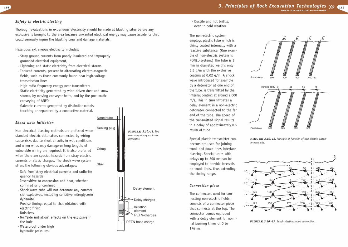
114
- Ductile and not brittle, even in cold weather
The non-electric systememploys plastic tube which isthinly coated internally with areactive substance. (One exam-ple of non-electric system isNONEL-system.) The tube is 3mm in diameter, weighs only5.5 g/m with the explosivecoating at 0.02 g/m. A shockwave introduced for exampleby a detonator at one end ofthe tube, is transmitted by theinternal coating at around 2.000m/s. This in turn initiates adelay element in a non-electricdetonator connected to the farend of the tube. The speed ofthe transmitted signal resultsin a delay of approximately 0.5ms/m of tube.
Special plastic transmitter con-nectors are used for joiningtrunk and down lines interfaceblasting. Special units withdelays up to 200 ms can beemployed to provide intervalson trunk lines, thus extendingthe timing range.
Connection piece
The connector, used for con-necting non-electric fields,consists of a connector piecethat connects at the top. Theconnector comes equippedwith a delay element for nomi-nal burning times of 0 to 176 ms.
1153. Principles of Rock Excavation TechnologiesROCK EXCAVATION HANDBOOK
Safety in electric blasting
Thorough evaluations in extraneous electricity should be made at blasting sites before anyexplosive is brought to the area because unwanted electrical energy may cause accidents thatcould seriously injure the blasting crew and damage materials.
Hazardous extraneous electricity includes:
- Stray ground currents from poorly insulated and improperlygrounded electrical equipment,
- Lightning and static electricity from electrical storms- Induced currents, present in alternating electro-magnetic
fields, such as those commonly found near high-voltage transmission lines
- High radio frequency energy near transmitters - Static electricity generated by wind-driven dust and snow
storms, by moving conveyor belts, and by the pneumatic conveying of ANFO
- Galvanic currents generated by dissimilar metalstouching or separated by a conductive material.
Shock wave initiation
Non-electrical blasting methods are preferred whenstandard electric detonators connected by wiringcause risks due to short circuits in wet conditionsand when wires may damage or long lengths ofvulnerable wiring are required. It is also preferredwhen there are special hazards from stray electriccurrents or static charges. The shock wave systemoffers the following obvious advantages:
- Safe from stray electrical currents and radio-frequency hazards
- Insensitive to concussion and heat, whether confined or unconfined
- Shock wave tube will not detonate any commercial explosives, including sensitive nitroglycerindynamite
- Precise timing, equal to that obtained with electric firing
- Noiseless- No “side initiation” effects on the explosive in
the hole- Waterproof under high
hydraulic pressures
FIGURE 3.10.-13. Bench blasting round connection.
FIGURE 3.10.-12. Principle of function of non-electric systemin open pits.
FIGURE 3.10.-11. Thenew non-primary explosivedetonator.
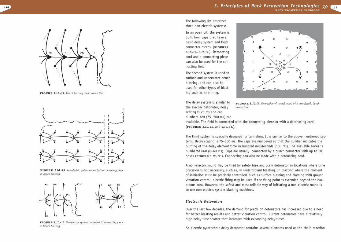
The following list describesthree non-electric systems:
In an open pit, the system isbuilt from caps that have abasic delay system and fieldconnector pieces. (FIGURES
3.10.-12...3.10.14.). Detonatingcord and a connecting piececan also be used for the con-necting field.
The second system is used insurface and underwater benchblasting, and can also beused for other types of blast-ing such as in mining.
The delay system is similar tothe electric detonator; delayscaling is 25 ms and capnumbers 320 (75 500 ms) areavailable. The field is connected with the connecting piece or with a detonating cord (FIGURES 3.10.-15. and 3.10.-16.).
The third system is specially designed for tunneling. It is similar to the above mentioned sys-tems. Delay scaling is 75–500 ms. The caps are numbered so that the number indicates theburning of the delay element time in hundred milliseconds (100 ms). The available series isnumbered 060 (0–60 ms). Caps are usually connected by a bunch connector with up to 20hoses (FIGURE 3.10.-17.). Connecting can also be made with a detonating cord.
A non-electric round may be fired by safety fuse and plain detonator in locations where timeprecision is not necessary, such as, in underground blasting. In blasting where the momentof initiation must be precisely controlled, such as surface blasting and blasting with groundvibration control, electric firing may be used if the firing point is extended beyond the haz-ardous area. However, the safest and most reliable way of initiating a non-electric round isto use non-electric system blasting machines.
Electronic Detonators
Over the last few decades, the demand for precision detonators has increased due to a needfor better blasting results and better vibration control. Current detonators have a relativelyhigh delay time scatter that increases with expanding delay times.
An electric pyrotechnic delay detonator contains several elements used as the chain reaction
117116 3. Principles of Rock Excavation TechnologiesROCK EXCAVATION HANDBOOK
FIGURE 3.10.-15. Non-electric system connected to connecting piecein bench blasting.
FIGURE 3.10.-16. Non-electric system connected to connecting piecein trench blasting.
FIGURE 3.10.17. Connection of tunnel round with non-electric bunchconnectors.
FIGURE 3.10.-14. Trench blasting round connection
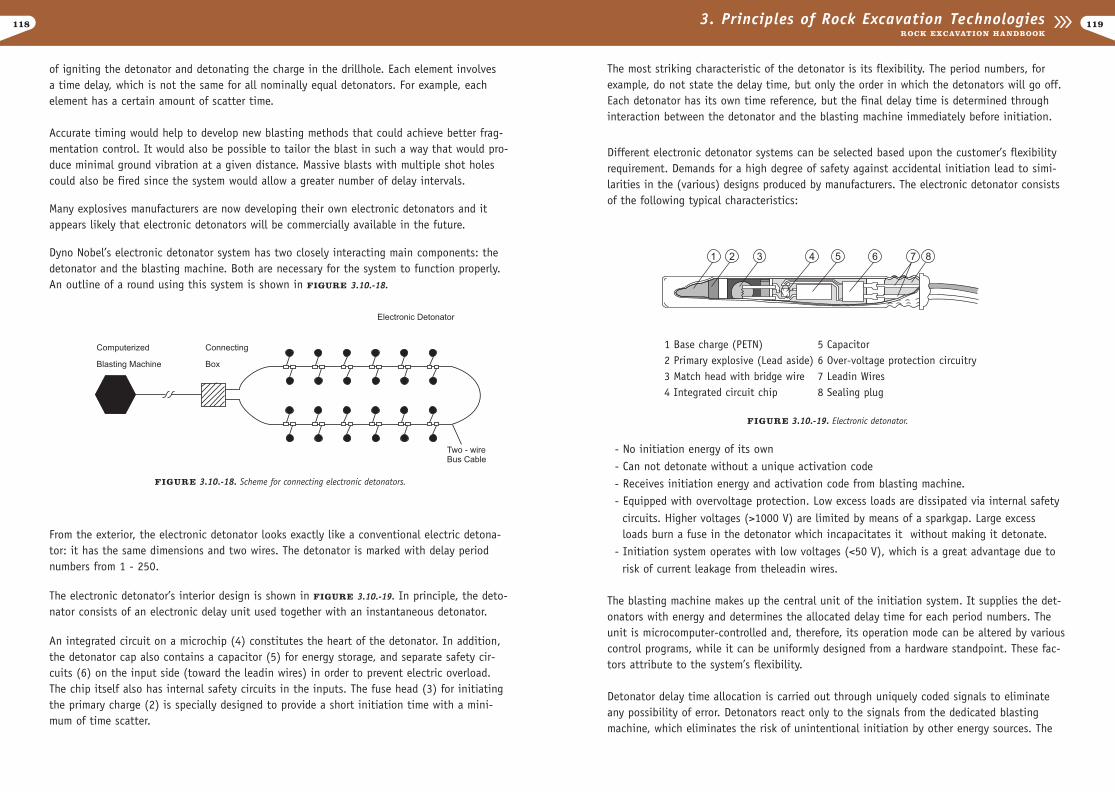
118
The most striking characteristic of the detonator is its flexibility. The period numbers, forexample, do not state the delay time, but only the order in which the detonators will go off.Each detonator has its own time reference, but the final delay time is determined throughinteraction between the detonator and the blasting machine immediately before initiation.
Different electronic detonator systems can be selected based upon the customer’s flexibilityrequirement. Demands for a high degree of safety against accidental initiation lead to simi-larities in the (various) designs produced by manufacturers. The electronic detonator consistsof the following typical characteristics:
- No initiation energy of its own- Can not detonate without a unique activation code- Receives initiation energy and activation code from blasting machine.- Equipped with overvoltage protection. Low excess loads are dissipated via internal safety
circuits. Higher voltages (>1000 V) are limited by means of a sparkgap. Large excessloads burn a fuse in the detonator which incapacitates it without making it detonate.
- Initiation system operates with low voltages (<50 V), which is a great advantage due to risk of current leakage from theleadin wires.
The blasting machine makes up the central unit of the initiation system. It supplies the det-onators with energy and determines the allocated delay time for each period numbers. Theunit is microcomputer-controlled and, therefore, its operation mode can be altered by variouscontrol programs, while it can be uniformly designed from a hardware standpoint. These fac-tors attribute to the system’s flexibility.
Detonator delay time allocation is carried out through uniquely coded signals to eliminateany possibility of error. Detonators react only to the signals from the dedicated blastingmachine, which eliminates the risk of unintentional initiation by other energy sources. The
1193. Principles of Rock Excavation TechnologiesROCK EXCAVATION HANDBOOK
of igniting the detonator and detonating the charge in the drillhole. Each element involves a time delay, which is not the same for all nominally equal detonators. For example, eachelement has a certain amount of scatter time.
Accurate timing would help to develop new blasting methods that could achieve better frag-mentation control. It would also be possible to tailor the blast in such a way that would pro-duce minimal ground vibration at a given distance. Massive blasts with multiple shot holescould also be fired since the system would allow a greater number of delay intervals.
Many explosives manufacturers are now developing their own electronic detonators and itappears likely that electronic detonators will be commercially available in the future.
Dyno Nobel’s electronic detonator system has two closely interacting main components: thedetonator and the blasting machine. Both are necessary for the system to function properly.An outline of a round using this system is shown in FIGURE 3.10.-18.
From the exterior, the electronic detonator looks exactly like a conventional electric detona-tor: it has the same dimensions and two wires. The detonator is marked with delay periodnumbers from 1 - 250.
The electronic detonator’s interior design is shown in FIGURE 3.10.-19. In principle, the deto-nator consists of an electronic delay unit used together with an instantaneous detonator.
An integrated circuit on a microchip (4) constitutes the heart of the detonator. In addition,the detonator cap also contains a capacitor (5) for energy storage, and separate safety cir-cuits (6) on the input side (toward the leadin wires) in order to prevent electric overload.The chip itself also has internal safety circuits in the inputs. The fuse head (3) for initiatingthe primary charge (2) is specially designed to provide a short initiation time with a mini-mum of time scatter.
FIGURE 3.10.-18. Scheme for connecting electronic detonators.
1 Base charge (PETN) 5 Capacitor2 Primary explosive (Lead aside) 6 Over-voltage protection circuitry3 Match head with bridge wire 7 Leadin Wires4 Integrated circuit chip 8 Sealing plug
FIGURE 3.10.-19. Electronic detonator.
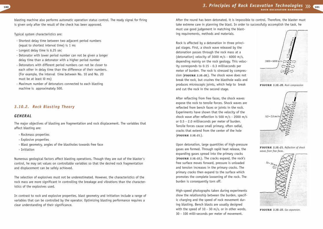
120
After the round has been detonated, it is impossible to control. Therefore, the blaster musttake extreme care in planning the blast. In order to successfully accomplish the task, hemust use good judgement in matching the blast-ing requirements, methods and materials.
Rock is affected by a detonation in three princi-pal stages. First, a shock wave released by thedetonation passes through the rock mass at a(detonation) velocity of 3000 m/s - 6000 m/s,depending mainly on the rock geology. This veloc-ity corresponds to 0.15 - 0.3 milliseconds permeter of burden. The rock is stressed by compres-sion (FIGURE 3.10.-20.). The shock wave does notbreak the rock, but crushes the blasthole walls andproduces microscopic joints, which help to breakand cut the rock in the second stage.
After reflecting from free faces, the shock wavesexpose the rock to tensile forces. Shock waves arereflected from bench faces or joints in the rock.Experiments have shown that the velocity of theshock wave after reflection is 500 m/s - 2000 m/sor 0.5 - 2.0 milliseconds per meter of burden.Tensile forces cause small primary, often radial,cracks that extend from the center of the hole(FIGURE 3.10.-21.).
Upon detonation, large quantities of high-pressuregases are formed. Through rapid heat release, theexpanding gases spread into the primary cracks(FIGURE 3.10.-22.). The cracks expand, the rock’sfree surface moves forward, pressure is unloadedand tension increases in the primary cracks. Theprimary cracks then expand to the surface whichpromotes the complete loosening of the rock. Theburden is consequently torn off.
High-speed photographs taken during experimentsshow the relationship between the burden, specif-ic charging and the speed of rock movement dur-ing blasting. Bench blasts are usually designedwith the speed of 10 - 30 m/s, or in other words,30 - 100 milli-seconds per meter of movement.
1213. Principles of Rock Excavation TechnologiesROCK EXCAVATION HANDBOOK
blasting machine also performs automatic operation status control. The ready signal for firingis given only after the result of the check has been approved.
Typical system characteristics are:
- Shortest delay time between two adjacent period numbers(equal to shortest interval time) is 1 ms
- Longest delay time is 6.25 sec- Detonator with lower period number can not be given a longer
delay time than a detonator with a higher period number- Detonators with different period numbers can not be closer to
each other in delay time than the difference of their numbers.(For example, the interval time between No. 10 and No. 20 must be at least l0 ms)
- Maximum number of detonators connected to each blasting machine is approximately 500.
3.10.2. Rock Blasting Theory
GENERAL
The major objectives of blasting are fragmentation and rock displacement. The variables thataffect blasting are:
- Rockmass properties - Explosive properties- Blast geometry, angles of the blastholes towards free face- Initiation
Numerous geological factors affect blasting operations. Though they are out of the blaster´scontrol, he may set values on controllable variables so that the desired rock fragmentationand displacement can be safely achieved.
The selection of explosives must not be underestimated. However, the characteristics of therock mass are more significant in controlling the breakage and vibrations than the character-istics of the explosives used.
In contrast to rock and explosive properties, blast geometry and initiation include a range ofvariables that can be controlled by the operator. Optimizing blasting performance requires aclear understanding of their significance.
FIGURE 3.10.-20. Rock compression
FIGURE 3.10.-21. Reflection of shockwaves from free faces.
FIGURE 3.10.-22. Gas expansion.
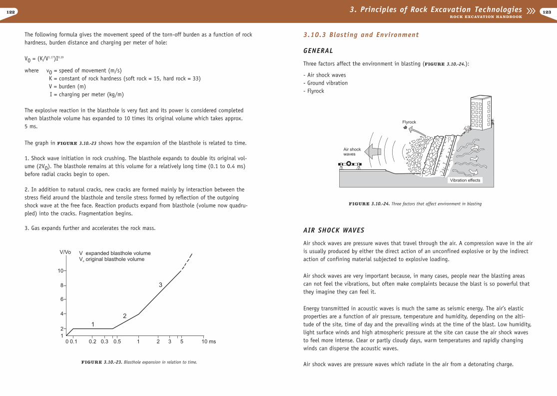
122
3.10.3 Blasting and Environment
GENERAL
Three factors affect the environment in blasting (FIGURE 3.10.-24.):
- Air shock waves- Ground vibration- Flyrock
AIR SHOCK WAVES
Air shock waves are pressure waves that travel through the air. A compression wave in the airis usually produced by either the direct action of an unconfined explosive or by the indirectaction of confining material subjected to explosive loading.
Air shock waves are very important because, in many cases, people near the blasting areascan not feel the vibrations, but often make complaints because the blast is so powerful thatthey imagine they can feel it.
Energy transmitted in acoustic waves is much the same as seismic energy. The air’s elasticproperties are a function of air pressure, temperature and humidity, depending on the alti-tude of the site, time of day and the prevailing winds at the time of the blast. Low humidity,light surface winds and high atmospheric pressure at the site can cause the air shock wavesto feel more intense. Clear or partly cloudy days, warm temperatures and rapidly changingwinds can disperse the acoustic waves.
Air shock waves are pressure waves which radiate in the air from a detonating charge.
1233. Principles of Rock Excavation TechnologiesROCK EXCAVATION HANDBOOK
The following formula gives the movement speed of the torn-off burden as a function of rockhardness, burden distance and charging per meter of hole:
V0 = (K/V1.17)I0.39
where v0 = speed of movement (m/s)K = constant of rock hardness (soft rock = 15, hard rock = 33)V = burden (m)I = charging per meter (kg/m)
The explosive reaction in the blasthole is very fast and its power is considered completedwhen blasthole volume has expanded to 10 times its original volume which takes approx.5 ms.
The graph in FIGURE 3.10.-23 shows how the expansion of the blasthole is related to time.
1. Shock wave initiation in rock crushing. The blasthole expands to double its original vol-ume (2V0). The blasthole remains at this volume for a relatively long time (0.1 to 0.4 ms)before radial cracks begin to open.
2. In addition to natural cracks, new cracks are formed mainly by interaction between thestress field around the blasthole and tensile stress formed by reflection of the outgoingshock wave at the free face. Reaction products expand from blasthole (volume now quadru-pled) into the cracks. Fragmentation begins.
3. Gas expands further and accelerates the rock mass.
FIGURE 3.10.-23. Blasthole expansion in relation to time.
FIGURE 3.10.-24. Three factors that affect environment in blasting
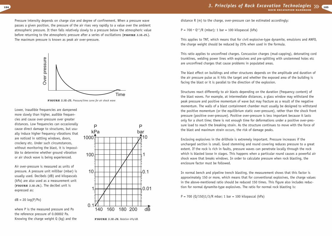
124
distance R (m) to the charge, over-pressure can be estimated accordingly:
P = 700 • Q1/3/R (mbar); 1 bar = 100 kilopascal (kPa)
This applies to TNT, which means that for civil explosive-type dynamite, emulsions and ANFO,the charge weight should be reduced by 25% when used in the formula.
This ratio applies to unconfined charges. Concussion charges (mud-capping), detonating cordtrunklines, welding power lines with explosives and pre-splitting with unstemmed holes etcare unconfined charges that cause problems in populated areas.
The blast effect on buildings and other structures depends on the amplitude and duration ofthe air pressure pulse as it hits the target and whether the exposed area of the building isfacing the blast or it is parallel to the direction of the explosion.
Structures react differently to air blasts depending on the duration (frequency content) ofthe blast waves. For example, at intermediate distances, a glass window may withstand thepeak pressure and positive momentum of wave but may fracture as a result of the negativemomentum. The walls of a blast containment chamber must usually be designed to withstandthe positive momentum (or the equilibrium static over-pressure), rather than the shock frontpressure (positive over-pressure). Positive over-pressure is less important because it lastsonly for a short time; there is not enough time for deformations under a positive over-pres-sure load to reach the breaking strain. As the structure continues to move with the force ofthe blast and maximum strain occurs, the risk of damage peaks.
Enclosing explosives in the drillhole is extremely important. Pressure increases if theuncharged section is small. Good stemming and round covering reduces pressure to a greatextent. If the rock is rich in faults, pressure waves can penetrate locally through the rockwhich is blasted loose in stages. This happens when a particular round causes a powerful airshock wave that breaks windows. In order to calculate pressure when rock blasting, theenclosure factor must be followed.
In normal bench and pipeline trench blasting, the measurement shows that this factor isapproximately 150 or more, which means that for conventional explosives, the charge valuesin the above-mentioned ratio should be reduced 150 times. This figure also includes reduc-tion for normal dynamite-type explosives. The ratio for normal rock blasting is:
P = 700 (Q/150)1/3/R mbar; 1 bar = 100 kilopascal (kPa)
1253. Principles of Rock Excavation TechnologiesROCK EXCAVATION HANDBOOK
Pressure intensity depends on charge size and degree of confinement. When a pressure wavepasses a given position, the pressure of the air rises very rapidly to a value over the ambientatmospheric pressure. It then falls relatively slowly to a pressure below the atmospheric valuebefore returning to the atmospheric pressure after a series of oscillations (FIGURE 3.10.-25.).The maximum pressure is known as peak air over-pressure.
FIGURE 3.10.-25. Pressure/time curve for air shock wave
Lower, inaudible frequencies are dampenedmore slowly than higher, audible frequen-cies and cause over-pressure over greaterdistances. Low frequencies can occasionallycause direct damage to structures, but usu-ally induce higher frequency vibrations thatare noticed in rattling windows, doors,crockery etc. Under such circumstances,without monitoring the blast, it is impossi-ble to determine whether ground vibrationor air shock wave is being experienced.
Air over-pressure is measured as units ofpressure. A pressure unit millibar (mbar) isusually used. Decibels (dB) and kilopascals(kPa) are also used as a measurement unit(FIGURE 3.10.-26.). The decibel unit isexpressed as:
dB = 20 log(P/Po)
where P is the measured pressure and Pothe reference pressure of 0.00002 Pa.Knowing the charge weight Q (kg) and the FIGURE 3.10.-26. Relation kPa/dB.
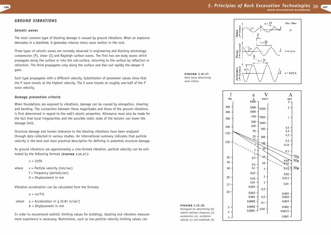
126 1273. Principles of Rock Excavation TechnologiesROCK EXCAVATION HANDBOOK
GROUND VIBRATIONS
Seismic waves
The most common type of blasting damage is caused by ground vibrations. When an explosivedetonates in a blasthole, it generates intense stress wave motion in the rock.
Three types of seismic waves are normally observed in engineering and blasting seismology:compression (P), shear (S) and Rayleigh surface waves. The first two are body waves whichpropagate along the surface or into the sub-surface, returning to the surface by reflection orrefraction. The third propagates only along the surface and dies out rapidly the deeper itgoes.
Each type propagates with a different velocity. Substitution of parameter values show thatthe P wave travels at the highest velocity. The S wave travels at roughly one-half of the Pwave velocity.
Damage prevention criteria
When foundations are exposed to vibrations, damage can be caused by elongation, shearingand bending. The connection between these magnitudes and those of the ground vibrations is first determined in regard to the wall’s elastic properties. Allowance must also be made forthe fact that local irregularities and the possible static state of the tension can lower thedamage limit.
Structure damage and human tolerance to the blasting vibrations have been analyzedthrough data collected in various studies. An international summary indicates that particlevelocity is the best and most practical description for defining in potential structure damage.
As ground vibrations are approximately a sine-formed vibration, particle velocity can be esti-mated by the following formula (FIGURE 3.10.-27.):
v = 2¹fA
where v = Particle velocity (mm/sec)f = Frequency (periods/sec)A = Displacement in mm
Vibration acceleration can be calculated from the formula:
a = 4¹2f2A
where a = Acceleration in g (9.81 m/sec2)A = Displacement in mm
In order to recommend realistic limiting values for buildings, blasting and vibration measure-ment experience is necessary. Restrictions, such as low-particle velocity limiting values can
FIGURE 3.10.-28.Nomogram for determining therelation between frequency (f),acceleration (a), oscillationvelocity (v) and amplitude (A).
FIGURE 3.10.-27.Basis terms determiningwave motion.
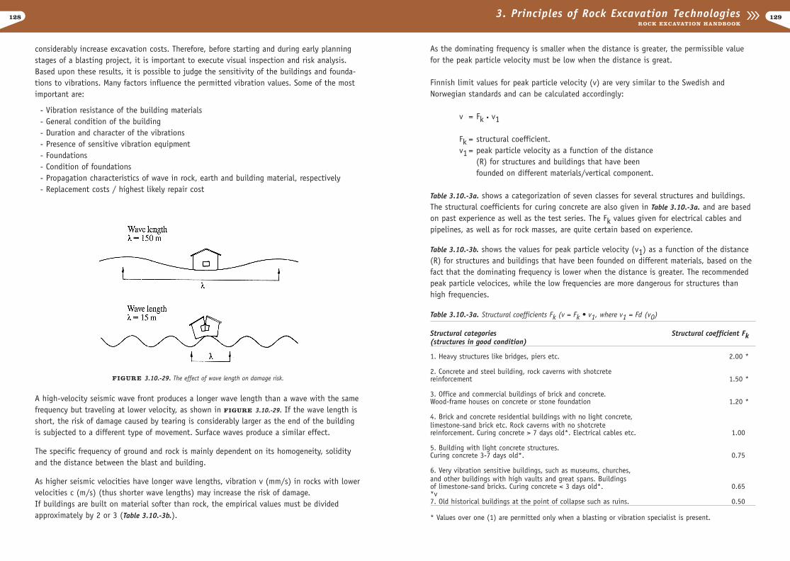
128
As the dominating frequency is smaller when the distance is greater, the permissible valuefor the peak particle velocity must be low when the distance is great.
Finnish limit values for peak particle velocity (v) are very similar to the Swedish andNorwegian standards and can be calculated accordingly:
v = Fk • v1
Fk = structural coefficient.v1 = peak particle velocity as a function of the distance
(R) for structures and buildings that have been founded on different materials/vertical component.
Table 3.10.-3a. shows a categorization of seven classes for several structures and buildings.The structural coefficients for curing concrete are also given in Table 3.10.-3a. and are basedon past experience as well as the test series. The Fk values given for electrical cables andpipelines, as well as for rock masses, are quite certain based on experience.
Table 3.10.-3b. shows the values for peak particle velocity (v1) as a function of the distance(R) for structures and buildings that have been founded on different materials, based on thefact that the dominating frequency is lower when the distance is greater. The recommendedpeak particle velocices, while the low frequencies are more dangerous for structures thanhigh frequencies.
1293. Principles of Rock Excavation TechnologiesROCK EXCAVATION HANDBOOK
considerably increase excavation costs. Therefore, before starting and during early planningstages of a blasting project, it is important to execute visual inspection and risk analysis.Based upon these results, it is possible to judge the sensitivity of the buildings and founda-tions to vibrations. Many factors influence the permitted vibration values. Some of the mostimportant are:
- Vibration resistance of the building materials- General condition of the building- Duration and character of the vibrations- Presence of sensitive vibration equipment- Foundations- Condition of foundations- Propagation characteristics of wave in rock, earth and building material, respectively- Replacement costs / highest likely repair cost
A high-velocity seismic wave front produces a longer wave length than a wave with the samefrequency but traveling at lower velocity, as shown in FIGURE 3.10.-29. If the wave length isshort, the risk of damage caused by tearing is considerably larger as the end of the buildingis subjected to a different type of movement. Surface waves produce a similar effect.
The specific frequency of ground and rock is mainly dependent on its homogeneity, solidityand the distance between the blast and building.
As higher seismic velocities have longer wave lengths, vibration v (mm/s) in rocks with lowervelocities c (m/s) (thus shorter wave lengths) may increase the risk of damage.If buildings are built on material softer than rock, the empirical values must be dividedapproximately by 2 or 3 (Table 3.10.-3b.).
Table 3.10.-3a. Structural coefficients Fk (v = Fk • v1, where v1 = Fd (v0)
Structural categories Structural coefficient Fk(structures in good condition)
1. Heavy structures like bridges, piers etc. 2.00 *
2. Concrete and steel building, rock caverns with shotcrete reinforcement 1.50 *
3. Office and commercial buildings of brick and concrete. Wood-frame houses on concrete or stone foundation 1.20 *
4. Brick and concrete residential buildings with no light concrete, limestone-sand brick etc. Rock caverns with no shotcrete reinforcement. Curing concrete > 7 days old*. Electrical cables etc. 1.00*
5. Building with light concrete structures. Curing concrete 3-7 days old*. 0.75*
6. Very vibration sensitive buildings, such as museums, churches, and other buildings with high vaults and great spans. Buildings of limestone-sand bricks. Curing concrete < 3 days old*. 0.65**v7. Old historical buildings at the point of collapse such as ruins. 0.50*
* Values over one (1) are permitted only when a blasting or vibration specialist is present.
FIGURE 3.10.-29. The effect of wave length on damage risk.
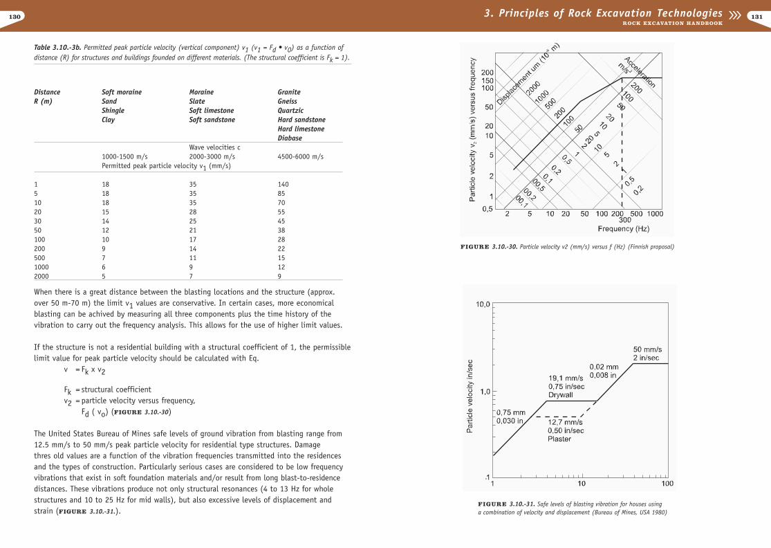
130 1313. Principles of Rock Excavation TechnologiesROCK EXCAVATION HANDBOOK
Table 3.10.-3b. Permitted peak particle velocity (vertical component) v1 (v1 = Fd • v0) as a function ofdistance (R) for structures and buildings founded on different materials. (The structural coefficient is Fk = 1).
When there is a great distance between the blasting locations and the structure (approx.over 50 m-70 m) the limit v1 values are conservative. In certain cases, more economicalblasting can be achived by measuring all three components plus the time history of thevibration to carry out the frequency analysis. This allows for the use of higher limit values.
If the structure is not a residential building with a structural coefficient of 1, the permissiblelimit value for peak particle velocity should be calculated with Eq.
v = Fk x v2
Fk = structural coefficient v2 = particle velocity versus frequency,
Fd ( vo) (FIGURE 3.10.-30)
The United States Bureau of Mines safe levels of ground vibration from blasting range from12.5 mm/s to 50 mm/s peak particle velocity for residential type structures. Damage thres old values are a function of the vibration frequencies transmitted into the residencesand the types of construction. Particularly serious cases are considered to be low frequency vibrations that exist in soft foundation materials and/or result from long blast-to-residence distances. These vibrations produce not only structural resonances (4 to 13 Hz for wholestructures and 10 to 25 Hz for mid walls), but also excessive levels of displacement andstrain (FIGURE 3.10.-31.).
Distance Soft moraine Moraine GraniteR (m) Sand Slate Gneiss
Shingle Soft limestone QuartzicClay Soft sandstone Hard sandstone
Hard limestoneDiabase
Wave velocities c1000-1500 m/s 2000-3000 m/s 4500-6000 m/sPermitted peak particle velocity v1 (mm/s)
1 18 35 1405 18 35 8510 18 35 7020 15 28 5530 14 25 4550 12 21 38100 10 17 28200 9 14 22500 7 11 151000 6 9 122000 5 7 9
FIGURE 3.10.-30. Particle velocity v2 (mm/s) versus f (Hz) (Finnish proposal)
FIGURE 3.10.-31. Safe levels of blasting vibration for houses using a combination of velocity and displacement (Bureau of Mines, USA 1980)
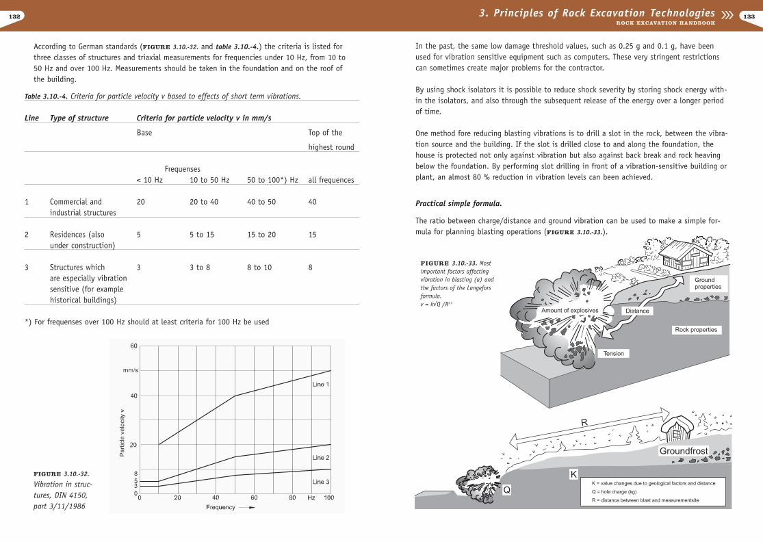
133132 3. Principles of Rock Excavation TechnologiesROCK EXCAVATION HANDBOOK
According to German standards (FIGURE 3.10.-32. and table 3.10.-4.) the criteria is listed forthree classes of structures and triaxial measurements for frequencies under 10 Hz, from 10 to 50 Hz and over 100 Hz. Measurements should be taken in the foundation and on the roof ofthe building.
Table 3.10.-4. Criteria for particle velocity v based to effects of short term vibrations.
Line Type of structure Criteria for particle velocity v in mm/s
Base Top of the
hi highest round
Frequenses< 10 Hz 10 to 50 Hz 50 to 100*) Hz all frequences
1 Commercial and 20 20 to 40 40 to 50 40industrial structures
2 Residences (also 5 5 to 15 15 to 20 15under construction)
3 Structures which 3 3 to 8 8 to 10 8are especially vibration sensitive (for example historical buildings)
*) For frequenses over 100 Hz should at least criteria for 100 Hz be used
FIGURE 3.10.-32.
Vibration in struc-tures, DIN 4150,part 3/11/1986
FIGURE 3.10.-33. Mostimportant factors affectingvibration in blasting (a) andthe factors of the Langeforsformula.v = kÃQ /R1,5
In the past, the same low damage threshold values, such as 0.25 g and 0.1 g, have beenused for vibration sensitive equipment such as computers. These very stringent restrictionscan sometimes create major problems for the contractor.
By using shock isolators it is possible to reduce shock severity by storing shock energy with-in the isolators, and also through the subsequent release of the energy over a longer periodof time.
One method fore reducing blasting vibrations is to drill a slot in the rock, between the vibra-tion source and the building. If the slot is drilled close to and along the foundation, thehouse is protected not only against vibration but also against back break and rock heavingbelow the foundation. By performing slot drilling in front of a vibration-sensitive building orplant, an almost 80 % reduction in vibration levels can been achieved.
Practical simple formula.
The ratio between charge/distance and ground vibration can be used to make a simple for-mula for planning blasting operations (FIGURE 3.10.-33.).
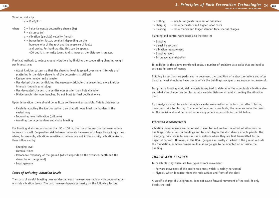
134
- Drilling - smaller or greater number of drillholes.- Charging - more detonators and higher labor costs- Blasting - more rounds and longer standup time special charges
Planning and control work costs also increase in:
- Blasting- Visual inspections- Vibration measurement- Blasting record- Insurance administration
In addition to the above-mentioned costs, a number of problems also exist that are hard toestimate in terms of money.
Building inspections are performed to document the condition of a structure before and afterblasting. Most structures have cracks which the building’s occupants are usually not aware of.
To optimize blasting work, risk analysis is required to determine the acceptable vibration sizeand what size charge can be blasted at a certain distance without exceeding the vibrationlimit.
Risk analysis should be made through a careful examination of factors that affect blastingoperations prior to blasting. The more information is available, the more accurate the resultis. The decision should be based on as many points as possible in the list below.
Vibration measurements
Vibration measurements are performed to monitor and control the effect of vibrations onbuildings, installations in buildings and to what degree the disturbance affects people. Theunderlying principle is to measure the vibrations where they are first transmitted to theobject of concern. However, in the USA., gauges are usually attached to the ground outsidethe foundation, as home owners seldom allow gauges to be mounted on or inside the building.
THROW AND FLYROCK
In bench blasting, there are two types of rock movement:
- Forward movement of the entire rock mass which is mainly horizontal- Flyrock, which is scatter from the rock surface and front of the blast
A specific charge of 0.2 kg/cu.m. does not cause forward movement of the rock; it onlybreaks the rock.
1353. Principles of Rock Excavation TechnologiesROCK EXCAVATION HANDBOOK
Vibration velocity: v = K ÃQ/R 1,5
where Q = instantaneously detonating charge (kg)R = distance (m)v = vibration (particle) velocity (mm/s)K = transmission factor, constant depending on the
homogeneity of the rock and the presence of faultsand cracks. For hard granite, this can be approx. 400 but it is normally lower. And is lower as the distance is greater.
Practical methods to reduce ground vibrations by limiting the cooperating charging weightper interval are:
- Adapt ignition pattern so that the charging level is spread over more intervals and scattering in the delay elements of the detonators is utilized
- Reduce hole number and diameter- Use decked charges by dividing the necessary drillhole chargeevel into more ignition
intervals through sand plugs - Use decoupled charges; charge diameter smaller than hole diameter- Divide bench into more benches. Do not blast to final depth at once.
Upon detonation, there should be as little confinement as possible. This is obtained by:
- Carefully adapting the ignition pattern, so that all holes break the burden in the easiest way
- Increasing hole inclination (drillhole)- Avoiding too large burdens and choke blasting
For blasting at distances shorter than 50 - 100 m, the risk of interaction between variousintervals is small. Cooperation risk between intervals increases with large blasts in quarries,where, for example, vibration- sensitive structures are not in the vicinity. Vibration size isthen influenced by:
- Charging level- Interval times- Resonance frequency of the ground (which depends on the distance, depth and the
character of the ground)- Local geology
Costs of reducing vibration levels
The costs of careful blasting near residential areas increase very rapidly with decreasing per-missible vibration levels. The cost increase depends primarily on the following factors:
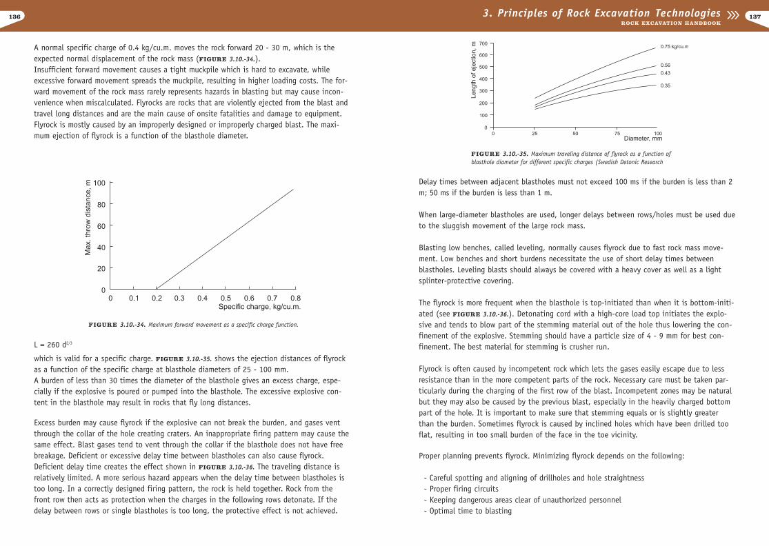
136
Delay times between adjacent blastholes must not exceed 100 ms if the burden is less than 2m; 50 ms if the burden is less than 1 m.
When large-diameter blastholes are used, longer delays between rows/holes must be used dueto the sluggish movement of the large rock mass.
Blasting low benches, called leveling, normally causes flyrock due to fast rock mass move-ment. Low benches and short burdens necessitate the use of short delay times betweenblastholes. Leveling blasts should always be covered with a heavy cover as well as a lightsplinter-protective covering.
The flyrock is more frequent when the blasthole is top-initiated than when it is bottom-initi-ated (see FIGURE 3.10.-36.). Detonating cord with a high-core load top initiates the explo-sive and tends to blow part of the stemming material out of the hole thus lowering the con-finement of the explosive. Stemming should have a particle size of 4 - 9 mm for best con-finement. The best material for stemming is crusher run.
Flyrock is often caused by incompetent rock which lets the gases easily escape due to lessresistance than in the more competent parts of the rock. Necessary care must be taken par-ticularly during the charging of the first row of the blast. Incompetent zones may be naturalbut they may also be caused by the previous blast, especially in the heavily charged bottompart of the hole. It is important to make sure that stemming equals or is slightly greaterthan the burden. Sometimes flyrock is caused by inclined holes which have been drilled tooflat, resulting in too small burden of the face in the toe vicinity.
Proper planning prevents flyrock. Minimizing flyrock depends on the following:
- Careful spotting and aligning of drillholes and hole straightness- Proper firing circuits- Keeping dangerous areas clear of unauthorized personnel- Optimal time to blasting
1373. Principles of Rock Excavation TechnologiesROCK EXCAVATION HANDBOOK
A normal specific charge of 0.4 kg/cu.m. moves the rock forward 20 - 30 m, which is theexpected normal displacement of the rock mass (FIGURE 3.10.-34.).Insufficient forward movement causes a tight muckpile which is hard to excavate, whileexcessive forward movement spreads the muckpile, resulting in higher loading costs. The for-ward movement of the rock mass rarely represents hazards in blasting but may cause incon-venience when miscalculated. Flyrocks are rocks that are violently ejected from the blast andtravel long distances and are the main cause of onsite fatalities and damage to equipment.Flyrock is mostly caused by an improperly designed or improperly charged blast. The maxi-mum ejection of flyrock is a function of the blasthole diameter.
L = 260 d2/3
which is valid for a specific charge. FIGURE 3.10.-35. shows the ejection distances of flyrockas a function of the specific charge at blasthole diameters of 25 - 100 mm.A burden of less than 30 times the diameter of the blasthole gives an excess charge, espe-cially if the explosive is poured or pumped into the blasthole. The excessive explosive con-tent in the blasthole may result in rocks that fly long distances.
Excess burden may cause flyrock if the explosive can not break the burden, and gases ventthrough the collar of the hole creating craters. An inappropriate firing pattern may cause thesame effect. Blast gases tend to vent through the collar if the blasthole does not have freebreakage. Deficient or excessive delay time between blastholes can also cause flyrock.Deficient delay time creates the effect shown in FIGURE 3.10.-36. The traveling distance isrelatively limited. A more serious hazard appears when the delay time between blastholes istoo long. In a correctly designed firing pattern, the rock is held together. Rock from thefront row then acts as protection when the charges in the following rows detonate. If thedelay between rows or single blastholes is too long, the protective effect is not achieved.
FIGURE 3.10.-34. Maximum forward movement as a specific charge function.
FIGURE 3.10.-35. Maximum traveling distance of flyrock as a function ofblasthole diameter for different specific charges (Swedish Detonic Research

138
generally requires more explosives, because backfill contains rock movement.
Blasting mats are made of netting or matting of either cable or tires. Covers efficiently pro-tect the site surroundings from flyrock. Covers should be strong and heavy, and contain allbursting blocks within the blast. The following rules should be followed when coveringblasts:
- Blast should be covered with both rubber mats and industrialfelts; these covers should exceed the blast boundaries by at least 2 - 3 meters (6 -10 ft). If the hole is loaded closeto the collar (i.e. stem decreased), at least two covers should be used,
- Rock from previous blasts should be used to cover the face of the blast; this decreases therisk of flyrock from a deficientburden in the bottom caused by hole deviation.
The main rule for blasting mats is never to blast more holes than can be safely covered withthe mats. As in backfilling, great care should be taken not to break leg wires when placingthe mats.
1393. Principles of Rock Excavation TechnologiesROCK EXCAVATION HANDBOOK
Safe blasting operations in residential areas require:
- Hole diameters less than 51 mm and cartridge diameters less than 40 mm- Selection of burden and spacing so that specific charging does not exceed 0.3 - 0.5 kg/m3
- For secondary blasting, the use of a suitable amount of charging - approx. 0.05 kg/m3. Drillhole length should be 2/3 of boulder height, with the hole drilled through the boulder’s center of gravity
- Charging should always be related to the burden; the blaster should always consider the effect of possible back break
- Holes should not be drilled into joints or shear zones; it is advantageous to use these zones as excavation boundaries
- Firing should be planned so that delays between adjacent holes do not exceed 50 ms. (Burden < 1m)
However, if these measures are not sufficient, the blaster must not resort to controlling fly-rock by covering the field with heavy blasting mats and backfill. These are generally onlyused in construction blasting.
Backfilling is a method that is used to cover a blast area with soil with no stones, preferablysand, to control or prevent undesirable flyrock.
A good rule of thumb for backfilling is that the backfill is equal in depth to the stemming;however, there must be a minimum of approximately one meter of backfill. When backfilling,the blaster must exercise extreme caution not to break the cap leg wires. Backfilling isworthwhile in that it requires less equipment than blasting mats, produces better breakageand the whole blast can be shot at once. On the other hand, using backfill for blast coverage
FIGURE 3.10.-36. Crater effect, vertical holes without free breakage.
FIGURE 3.10.-37. Using backfill.
FIGURE 3.10.-38. Using blasting mats and backfill to prevent flyrock.