Embed Size (px)
Citation preview
Quick Start Guide00825-0100-4834, Rev FA
March 2020
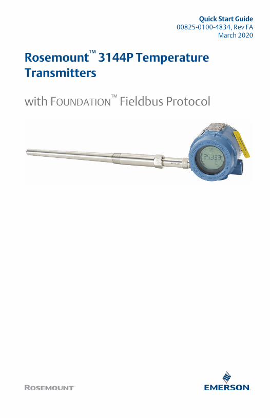
Rosemount™ 3144P TemperatureTransmitters
with FOUNDATION™ Fieldbus Protocol
ContentsAbout this guide...........................................................................................................................3
Mount the transmitter..................................................................................................................5
Wire and apply power...................................................................................................................7
Verify tagging............................................................................................................................ 12
Product certifications................................................................................................................. 16
Quick Start Guide March 2020
2 Rosemount 3144P
1 About this guide
This guide provides basic guidelines for installing the Rosemount 3144PTransmitter. It does not provide instructions for detailed configuration,diagnostics, maintenance, service, troubleshooting, Explosion-proof,Flameproof, or intrinsically safe (I.S.) installations. Refer to the Rosemount3144P Transmitter Reference Manual for more instructions. The manual andthis guide are also available electronically on Emerson.com/Rosemount.
WARNING
Explosions
Explosions could result in death or serious injury.
Installation of device in an explosive environment must be in accordancewith appropriate local, national, and international standards, codes, andpractices.Review the Product Certifications section of this document for anyrestrictions associated with a safe installation.In an Explosion-proof/Flameproof installation, do not remove thetransmitter covers when power is applied to the unit.
Process leaks
Process leaks may cause harm or result in death.
Install and tighten thermowells and sensors before applying pressure.Do not remove the thermowell while in operation.
Conduit/cable entries
The conduit/cable entries in the transmitter housing use a ½–14 NPTthread form.When installing in a hazardous location, use only appropriately listed orEx certified plugs, glands, or adapters in cable/conduit entries.
Electrical shock
Electrical shock can result in death or serious injury.
Avoid contact with the leads and terminals. High voltage that may bepresent on leads could cause electrical shock.
March 2020 Quick Start Guide
Quick Start Guide 3
WARNING
Physical access
Unauthorized personnel may potentially cause significant damage to and/ormisconfiguration of end users’ equipment. This could be intentional orunintentional and needs to be protected against.
Physical security is an important part of any security program andfundamental to protecting your system. Restrict physical access byunauthorized personnel to protect end users’ assets. This is true for allsystems used within the facility.
Quick Start Guide March 2020
4 Rosemount 3144P
2 Mount the transmitter
Mount the transmitter at a high point in the conduit run to prevent moisturefrom draining into the transmitter housing.
2.1 Typical North American installation
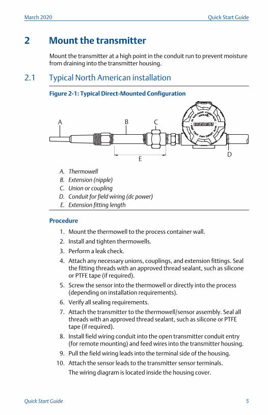
Figure 2-1: Typical Direct-Mounted Configuration
A B C
ED
A. ThermowellB. Extension (nipple)C. Union or couplingD. Conduit for field wiring (dc power)E. Extension fitting length
Procedure
1. Mount the thermowell to the process container wall.
2. Install and tighten thermowells.
3. Perform a leak check.
4. Attach any necessary unions, couplings, and extension fittings. Sealthe fitting threads with an approved thread sealant, such as siliconeor PTFE tape (if required).
5. Screw the sensor into the thermowell or directly into the process(depending on installation requirements).
6. Verify all sealing requirements.
7. Attach the transmitter to the thermowell/sensor assembly. Seal allthreads with an approved thread sealant, such as silicone or PTFEtape (if required).
8. Install field wiring conduit into the open transmitter conduit entry(for remote mounting) and feed wires into the transmitter housing.
9. Pull the field wiring leads into the terminal side of the housing.
10. Attach the sensor leads to the transmitter sensor terminals.
The wiring diagram is located inside the housing cover.
March 2020 Quick Start Guide
Quick Start Guide 5
11. Attach and tighten both transmitter covers.
2.2 Typical European installation
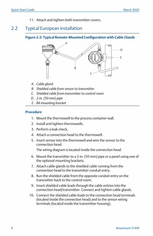
Figure 2-2: Typical Remote-Mounted Configuration with Cable Glands
A
B
C
D
E
A. Cable glandB. Shielded cable from sensor to transmitterC. Shielded cable from transmitter to control roomD. 2-in. (50 mm) pipeE. B4 mounting bracket
Procedure
1. Mount the thermowell to the process container wall.
2. Install and tighten thermowells.
3. Perform a leak check.
4. Attach a connection head to the thermowell.
5. Insert sensor into the thermowell and wire the sensor to theconnection head.
The wiring diagram is located inside the connection head.
6. Mount the transmitter to a 2-in. (50 mm) pipe or a panel using one ofthe optional mounting brackets.
7. Attach cable glands to the shielded cable running from theconnection head to the transmitter conduit entry.
8. Run the shielded cable from the opposite conduit entry on thetransmitter back to the control room.
9. Insert shielded cable leads through the cable entries into theconnection head/transmitter. Connect and tighten cable glands.
10. Connect the shielded cable leads to the connection head terminals(located inside the connection head) and to the sensor wiringterminals (located inside the transmitter housing).
Quick Start Guide March 2020
6 Rosemount 3144P
3 Wire and apply power
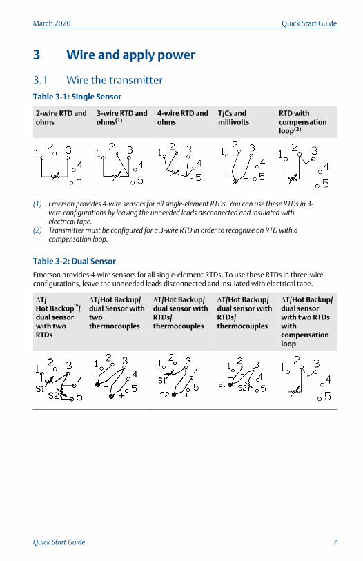
3.1 Wire the transmitterTable 3-1: Single Sensor
2-wire RTD andohms
3-wire RTD andohms(1)
4-wire RTD andohms
T/Cs andmillivolts
RTD withcompensationloop(2)
(1) Emerson provides 4-wire sensors for all single-element RTDs. You can use these RTDs in 3-wire configurations by leaving the unneeded leads disconnected and insulated withelectrical tape.
(2) Transmitter must be configured for a 3-wire RTD in order to recognize an RTD with acompensation loop.
Table 3-2: Dual Sensor
Emerson provides 4-wire sensors for all single-element RTDs. To use these RTDs in three-wireconfigurations, leave the unneeded leads disconnected and insulated with electrical tape.
ΔT/Hot Backup™/dual sensorwith twoRTDs
ΔT/Hot Backup/dual Sensor withtwothermocouples
ΔT/Hot Backup/dual sensor withRTDs/thermocouples
ΔT/Hot Backup/dual sensor withRTDs/thermocouples
ΔT/Hot Backup/dual sensorwith two RTDswithcompensationloop
March 2020 Quick Start Guide
Quick Start Guide 7
3.2 Power the transmitter
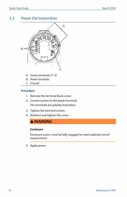
A. Sensor terminals (1–5)B. Power terminalsC. Ground
Procedure
1. Remove the terminal block cover.
2. Connect power to the power terminal.
The terminals are polarity insensitive.
3. Tighten the terminal screws.
4. Reattach and tighten the cover.
WARNING
Enclosure
Enclosure covers must be fully engaged to meet explosion-proofrequirements.
5. Apply power.
Quick Start Guide March 2020
8 Rosemount 3144P
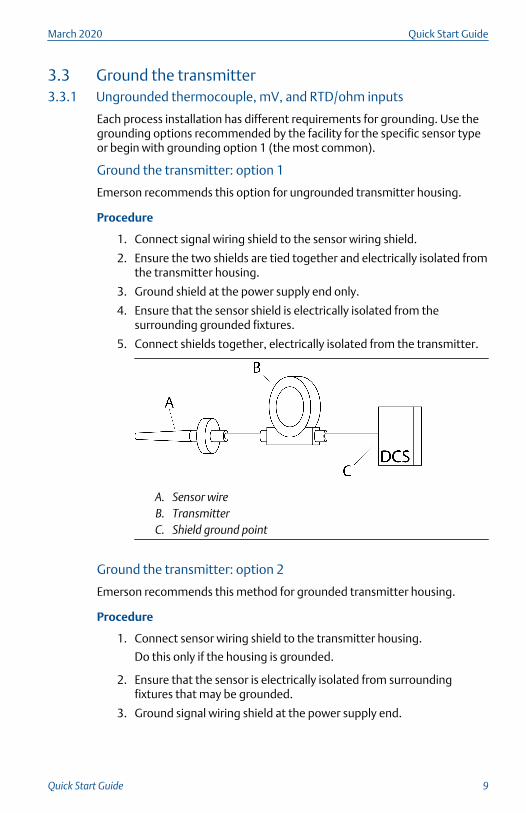
3.3 Ground the transmitter3.3.1 Ungrounded thermocouple, mV, and RTD/ohm inputs
Each process installation has different requirements for grounding. Use thegrounding options recommended by the facility for the specific sensor typeor begin with grounding option 1 (the most common).
Ground the transmitter: option 1
Emerson recommends this option for ungrounded transmitter housing.
Procedure
1. Connect signal wiring shield to the sensor wiring shield.
2. Ensure the two shields are tied together and electrically isolated fromthe transmitter housing.
3. Ground shield at the power supply end only.
4. Ensure that the sensor shield is electrically isolated from thesurrounding grounded fixtures.
5. Connect shields together, electrically isolated from the transmitter.
A. Sensor wireB. TransmitterC. Shield ground point
Ground the transmitter: option 2
Emerson recommends this method for grounded transmitter housing.
Procedure
1. Connect sensor wiring shield to the transmitter housing.
Do this only if the housing is grounded.
2. Ensure that the sensor is electrically isolated from surroundingfixtures that may be grounded.
3. Ground signal wiring shield at the power supply end.
March 2020 Quick Start Guide
Quick Start Guide 9
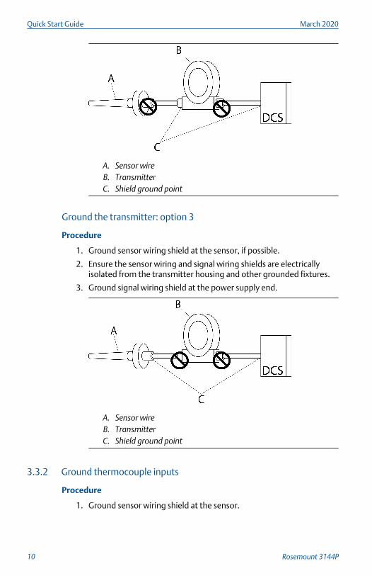
A. Sensor wireB. TransmitterC. Shield ground point
Ground the transmitter: option 3
Procedure
1. Ground sensor wiring shield at the sensor, if possible.
2. Ensure the sensor wiring and signal wiring shields are electricallyisolated from the transmitter housing and other grounded fixtures.
3. Ground signal wiring shield at the power supply end.
A. Sensor wireB. TransmitterC. Shield ground point
3.3.2 Ground thermocouple inputs
Procedure
1. Ground sensor wiring shield at the sensor.
Quick Start Guide March 2020
10 Rosemount 3144P
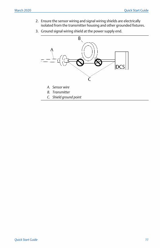
2. Ensure the sensor wiring and signal wiring shields are electricallyisolated from the transmitter housing and other grounded fixtures.
3. Ground signal wiring shield at the power supply end.
A. Sensor wireB. TransmitterC. Shield ground point
March 2020 Quick Start Guide
Quick Start Guide 11
4 Verify tagging
4.1 Commissioning (paper) tagTo identify which device is at a particular location use the removable tagprovided with the transmitter. Ensure the physical device tag (PD Tag field)is properly entered in both places on the removable commissioning tag andtear off the bottom portion for each transmitter.
NoteThe device description loaded in the host system must be at the samerevision as this device. You can download the device description fromEmerson.com/Rosemount.
4.1.1 Verify transmitter configuration
Each FOUNDATION Fieldbus host or configuration tool has a different way ofdisplaying and performing configurations. Some use Device Descriptions(DD) or DD methods for configuration and to display data consistentlyacross platforms. There is no requirement that a host or configuration toolsupport these features.
Quick Start Guide March 2020
12 Rosemount 3144P
The following is the minimum configuration requirement for a temperaturemeasurement. This guide is designed for systems not using DD methods. Fora complete list of parameters and configuration information, refer to theRosemount 3144P Temperature Transmitter Reference Manual.
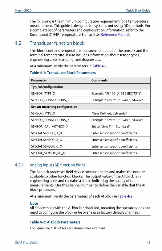
4.2 Transducer function blockThis block contains temperature measurement data for the sensors and theterminal temperature. It also includes information about sensor types,engineering units, damping, and diagnostics.
At a minimum, verify the parameters in Table 4-1.
Table 4-1: Transducer Block Parameters
Parameter Comments
Typical configuration
SENSOR_TYPE_X Example: “Pt 100_A_385 (IEC 751)”
SENSOR_CONNECTIONS_X Example: “2-wire”, “3-wire”, “4-wire”
Sensor matching configuration
SENSOR_TYPE_X “User Defined, Calvandu”
SENSOR_CONNECTIONS_X Example: “2-wire”, “3-wire”, “4-wire”
SENSOR_CAL_METHOD_X Set to “User Trim Standard”
SPECIAL SENSOR_A_X Enter sensor specific coefficients
SPECIAL SENSOR_B_X Enter sensor specific coefficients
SPECIAL SENSOR_C_X Enter sensor specific coefficients
SPECIAL_SENSOR_R0_X Enter sensor specific coefficients
4.2.1 Analog Input (AI) function block
The AI block processes field device measurements and makes the outputsavailable to other function blocks. The output value of the AI block is inengineering units and contains a status indicating the quality of themeasurements. Use the channel number to define the variable that the AIblock processes.
At a minimum, verify the parameters of each AI block in Table 4-2.
NoteAll devices ship with the AI blocks scheduled, meaning the operator does notneed to configure the block or he or she uses factory default channels.
Table 4-2: AI Block Parameters
Configure one AI Block for each desired measurement.
March 2020 Quick Start Guide
Quick Start Guide 13
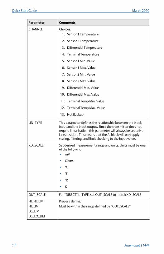
Parameter Comments
CHANNEL Choices:
1. Sensor 1 Temperature
2. Sensor 2 Temperature
3. Differential Temperature
4. Terminal Temperature
5. Sensor 1 Min. Value
6. Sensor 1 Max. Value
7. Sensor 2 Min. Value
8. Sensor 2 Max. Value
9. Differential Min. Value
10. Differential Max. Value
11. Terminal Temp Min. Value
12. Terminal Temp Max. Value
13. Hot Backup
LIN_TYPE This parameter defines the relationship between the blockinput and the block output. Since the transmitter does notrequire linearization, this parameter will always be set to NoLinearization. This means that the AI block will only applyscaling, filtering, and limit checking to the input value.
XD_SCALE Set desired measurement range and units. Units must be oneof the following:
• mV
• Ohms
• °C
• °F
• °R
• K
OUT_SCALE For “DIRECT” L_TYPE, set OUT_SCALE to match XD_SCALE
HI_HI_LIM
HI_LIM
LO_LIM
LO_LO_LIM
Process alarms.
Must be within the range defined by “OUT_SCALE”
Quick Start Guide March 2020
14 Rosemount 3144P
NoteTo make changes to the AI block, set the BLOCK_MODE (TARGET) to OOS(out of service). After making the changes, return the BLOCK_MODETARGET to AUTO.
4.2.2 Set switches
The security and simulate switches are located on the top center of theelectronics module.
NoteThe factory ships the simulate switch in the "ON" position.
Set the switches with an LCD display
Procedure
1. Set the loop to manual (if applicable) and disconnect the power.
2. Remove the electronics housing cover.
3. Unscrew the LCD display screws and gently slide the meter straightoff.
4. Set the alarm and security switches to the desired position.
5. Gently slide the LCD display back into place.
6. Replace and tighten the LCD display screws to secure the LCDdisplay.
7. Reattach housing cover.
8. Apply power and set the loop to automatic control.
Set the switches without an LCD display
Procedure
1. Set the loop to manual (if applicable) and disconnect the power.
2. Remove the electronics housing cover.
3. Set the alarm and security switches to the desired position.
4. Reattach housing cover.
5. Apply power and set the loop to automatic control.
March 2020 Quick Start Guide
Quick Start Guide 15
5 Product certifications
Rev 2.4
5.1 European Directive informationA copy of the EU Declaration of Conformity can be found at the end of theQuick Start Guide. The most recent revision of the EU Declaration ofConformity can be found at Emerson.com/Rosemount.
5.2 Ordinary location certificationAs standard, the transmitter has been examined and tested to determinethat the design meets the basic electrical, mechanical, and fire protectionrequirements by a nationally recognized test laboratory (NRTL) as accreditedby the Federal Occupational Safety and Health Administration (OSHA).
5.3 North America5.3.1 E5 FM Explosionproof, Dust-Ignitionproof, and Nonincendive
Certificate FM16US0202X
Standards FM Class 3600: 2011, FM Class 3611: 2004, FM Class 3615:2006, FM Class 3810: 2005, ANSI/NEMA 250: 1991, ANSI/ISA60079-0: 2009, ANSI/ISA 60079-11: 2009
Markings XP CL I, DIV 1, GP A, B, C, D; T5(-50 °C ≤ Ta ≤ +85 °C);
DIP CL II/III, DIV 1, GP E, F, G; T5(-50 °C ≤ Ta ≤ +75 °C); T6(-50°C ≤ Ta ≤ +60 °C); when installed per Rosemount drawing03144-0320;
NI CL I, DIV 2, GP A, B, C, D; T5(-60 °C ≤ Ta ≤ +75 °C); T6(-60 °C≤ Ta ≤+60 °C); when installed per Rosemount drawing03144-0321, 03144-5075.
5.3.2 I5 FM Intrinsic Safety and Nonincendive
Certificate FM16US0202X
Standards FM Class 3600: 2011, FM Class 3610: 2010, FM Class 3611:2004, FM Class 3810: 2005, ANSI/NEMA 250: 1991, ANSI/ISA60079-0: 2009, ANSI/ISA 60079-11: 2009
Markings IS CL I/II/III, DIV 1, GP A, B, C, D, E, F, G; T4(-60 °C ≤ Ta ≤ +60°C);
IS [Entity] CL I, Zone 0, AEx ia IIC T4(-60 °C ≤ Ta ≤ +60 °C);
NI CL I, DIV 2, GP A, B, C, D; T5(-60 °C ≤ Ta ≤ +75 °C); T6(-60 °C≤ Ta ≤ +60 °C); when installed per Rosemount drawing03144-0321, 03144-5075.
Quick Start Guide March 2020
16 Rosemount 3144P
5.3.3 I6 CSA Intrinisic Safety and Division 2
Certificate 1242650
Standards CAN/CSA C22.2 No. 0-M91 (R2001), CAN/CSA-C22.2 No. 94-M91, CSA Std C22.2 No. 142-M1987, CAN/CSA-C22.2 No.157-92, CSA Std C22.2 No. 213-M1987
Markings Intrinsically Safe for Class I Groups A, B, C, D; Class II, Groups E,F, G; Class III;
[HART only zone markings]: Intrinsically Safe for Class I Zone 0Group IIC; T4(-50 °C ≤ Ta ≤ +60 °C); Type 4X;
Suitable for Class I, Div. 2, Groups A, B, C, D;
[HART only zone markings]: Suitable for Class I Zone 2 GroupIIC; T6(-60 °C ≤ Ta ≤ +60 °C); T5(-60 °C ≤ Ta ≤ +85 °C); wheninstalled per Rosemount drawing 03144-5076.
5.3.4 K6 CSA Explosionproof, Intrinsic Safety, and Division 2
Certificate 1242650
Standards CAN/CSA C22.2 No. 0-M91 (R2001), CSA Std C22.2 No.25-1966, CSA Std C22.2 No. 30-M1986; CAN/CSA-C22.2 No.94-M91, CSA Std C22.2 No. 142-M1987, CAN/CSA-C22.2 No.157-92, CSA Std C22.2 No. 213-M1987
Markings Explosionproof for Class I, Groups A, B, C, D; Class II, Groups E,F, G; Class III;
[HART only zone markings]: Suitable for Class I Zone 1 GroupIIC; Intrinsically Safe for Class I Groups A, B, C, D; Class II,Groups E, F, G; Class III;
[HART only zone markings]: Suitable for Class I Zone 0 GroupIIC; T4(-50 °C ≤ Ta ≤ +60 °C); Type 4X; Suitable for Class I, Div.2, Groups A, B, C, D;
[HART only zone markings]: Suitable for Class I Zone 2 GroupIIC; T6(-60 °C ≤Ta ≤ +60 °C); T5(-60 °C ≤ Ta ≤ +85 °C); wheninstalled per Rosemount drawing 03144-5076.
5.4 Europe5.4.1 E1 ATEX Flameproof
Certificate FM12ATEX0065X
Standards EN 60079-0: 2012+A11:2013, EN 60079-1: 2014, EN60529:1991 +A1:2000+A2:2013
March 2020 Quick Start Guide
Quick Start Guide 17
Markings II 2 G Ex db IIC T6…T1 Gb, T6(-50 °C ≤ Ta ≤ +40 °C), T5…T1(-50 °C ≤ Ta ≤ +60 °C);See Process temperature limits for process temperatures.
Specific Conditions of Use (X):
1. See certificate for ambient temperature range.
2. The non-metallic label may store an electrostatic charge and becomea source of ignition in Group III environments.
3. Guard the LCD display cover against impact energies greater thanfour joules.
4. Flameproof joints are not intended for repair.
5. A suitable certified Ex d or Ex tb enclosure is required to be connectedto temperature probes with Enclosure option "N".
6. Care shall be taken by the end user to ensure that the externalsurface temperature on the equipment and the neck of DIN StyleSensor probe does not exceed 266 °F (130 °C).
7. Non-standard paint options may cause risk of electrostatic discharge.Avoid installations that cause electrostatic build-up on paintedsurfaces and only clean the painted surfaces with a damp cloth. Ifpaint is ordered through a special option code, contact themanufacturer for more information.
5.4.2 I1 ATEX Intrinsic Safety
Certificate BAS01ATEX1431X [HART]; Baseefa03ATEX0708X [Fieldbus]
Standards EN IEC 60079-0: 2018; EN 60079-11:2012
Markings HART: II 1 G Ex ia IIC T5/T6 Ga; T6(-60 °C ≤ Ta ≤ +50 °C),T5(-60 °C ≤ Ta ≤ +75 °C)
Fieldbus: II 1 G Ex ia IIC T4 Ga; T4(-60 °C ≤ Ta ≤ +60 °C)
See Table 5-9 for entity parameters.
Special Conditions for Safe Use (X):
1. When fitted with the transient terminal options, the equipment isnot capable of passing the 500 V insulation test. This must be takeninto account during installation.
2. The enclosure may be made from aluminum alloy with a protectivepolyurethane paint finish; however, care should be taken to protect itfrom impact or abrasion when located in Zone 0.
Quick Start Guide March 2020
18 Rosemount 3144P
5.4.3 N1 ATEX Type n
Certificate BAS01ATEX3432X [HART]; Baseefa03ATEX0709X [Fieldbus]
Standards EN IEC 60079-0:2018, EN 60079-15:2010
Markings HART: II 3 G Ex nA IIC T5/T6 Gc; T6(-40 °C ≤ Ta ≤ +50 °C),T5(-40 °C ≤ Ta ≤ +75 °C);
Fieldbus: II 3 G Ex nA IIC T5 Gc; T5(-40 °C ≤ Ta ≤ +75 °C);
Special Condition for Safe Use (X):
1. When fitted with the transient terminal options, the equipment isnot capable of passing the 500 V electrical strength test as defined inclause 6.5.1 of EN 60079-15: 2010. This must be taken into accountduring installation.
5.4.4 ND ATEX Dust
Certificate FM12ATEX0065X
Standards EN 60079-0: 2012+A11:2013, EN 60079-31:2014, EN60529:1991 +A1:2000+A2:2013
Markings II 2 D Ex tb IIIC T130°C Db, (-40 °C ≤ Ta ≤ +70 °C); IP66See Process temperature limits for process temperature.
Specific Conditions of Use (X):
1. See certificate for ambient temperature range.
2. The non-metallic label may store an electrostatic charge and becomea source of ignition in Group III environments.
3. Guard the LCD display cover against impact energies greater thanfour joules.
4. Flameproof joints are not intended for repair.
5. A suitable certified Ex d or Ex tb enclosure is required to be connectedto temperature probes with Enclosure option "N".
6. Care shall be taken by the end user to ensure that the externalsurface temperature on the equipment and the neck of DIN StyleSensor probe does not exceed 266 °F (130 °C).
7. Non-standard paint options may cause risk of electrostatic discharge.Avoid installations that cause electrostatic build-up on paintedsurfaces and only clean the painted surfaces with a damp cloth. Ifpaint is ordered through a special option code, contact themanufacturer for more information.
March 2020 Quick Start Guide
Quick Start Guide 19
5.5 International5.5.1 E7 IECEx Flameproof
Certificate IECEx FMG 12.0022X
Standards IEC 60079-0:2011, IEC 60079-1:2014-06
Markings Ex db IIC T6…T1 Gb, T6(-50 °C ≤ Ta ≤ +40 °C), T5…T1(-50 °C ≤Ta ≤ +60 °C)
See Process temperature limits for process temperatures.
Specific Conditions of Use (X):
1. See certificate for ambient temperature range.
2. The non-metallic label may store an electrostatic charge and becomea source of ignition in Group III environments.
3. Guard the LCD display cover against impact energies greater thanfour joules.
4. Flameproof joints are not intended for repair.
5. A suitable certified Ex d or Ex tb enclosure is required to be connectedto temperature probes with Enclosure option "N".
6. Care shall be taken by the end user to ensure that the externalsurface temperature on the equipment and the neck of DIN StyleSensor probe does not exceed 266 °F (130 °C).
7. Non-standard paint options may cause risk of electrostatic discharge.Avoid installations that cause electrostatic build-up on paintedsurfaces and only clean the painted surfaces with a damp cloth. Ifpaint is ordered through a special option code, contact themanufacturer for more information.
Additionally available with option K7
IECEx Dust
Certificate IECEx FMG 12.0022X
Standards IEC 60079-0:2011 and IEC 60079-31:2013
Markings Ex tb IIIC T130 °C Db, (-40 °C ≤ Ta ≤ +70 °C); IP66
See Process temperature limits for process temperatures.
Specific conditions of use (X):
1. See certificate for ambient temperature range.
Quick Start Guide March 2020
20 Rosemount 3144P
2. The non-metallic label may store an electrostatic charge and becomea source of ignition in Group III environments.
3. Guard the LCD display cover against impact energies greater thanfour joules.
4. Flameproof joints are not intended for repair.
5. A suitable certified Ex d or Ex tb enclosure is required to be connectedto temperature probes with Enclosure option "N".
6. Care shall be taken by the end user to ensure that the externalsurface temperature on the equipment and the neck of DIN StyleSensor probe does not exceed 266 °F (130 °C).
7. Non-standard paint options may cause risk of electrostatic discharge.Avoid installations that cause electrostatic build-up on paintedsurfaces and only clean the painted surfaces with a damp cloth. Ifpaint is ordered through a special option code, contact themanufacturer for more information.
5.5.2 I7 IECEx Intrinsic Safety
Certificate IECEx BAS 07.0002X [HART]; IECEx BAS 07.0004X [Fieldbus]
Standards IEC 60079-0: 2017; IEC 60079-11: 2011
Markings HART: Ex ia IIC T5/T6 Ga; T6(-60 °C ≤ Ta ≤ +50 °C), T5(-60 °C ≤Ta ≤ +75 °C);
Fieldbus: Ex ia IIC T4 Ga; T4(-60 °C ≤ Ta ≤ +60 °C)
See Table 5-9 for entity parameters.
Special Conditions for Safe Use (X):
1. When fitted with the transient terminal options, the equipment isnot capable of passing the 500 V electrical strength test as defined inClause 6.3.13 of IEC 60079-11: 2011. This must be taken intoaccount during installation.
2. The enclosure may be made from aluminum alloy with a protectivepolyurethane paint finish; however, care should be taken to protect itfrom impact or abrasion when located in Zone 0.
5.5.3 N7 IECEx Type n
Certificate IECEx BAS 07.0003X [HART]; IECEx BAS 07.0005X [Fieldbus]
Standards IEC 60079-0:2017, IEC 60079-15:2010
Markings HART: Ex nA IIC T5/T6 Gc; T6(-40 °C ≤ Ta ≤ +50 °C), T5(-40 °C ≤Ta ≤ +75 °C);Fieldbus: Ex nA IIC T5 Gc; T5(-40 °C ≤ Ta ≤ +75 °C);
March 2020 Quick Start Guide
Quick Start Guide 21
Special Condition for Safe Use (X):
1. When fitted with the transient terminal options, the equipment isnot capable of passing the 500 V electrical strength test as defined inclause 6.5.1 of EN 60079-15: 2010. This must be taken into accountduring installation.
5.6 Brazil5.6.1 E2 INMETRO Flameproof and Dust
Certificate UL-BR 13.0535X
Standards ABNT NBR IEC 60079-0:2013; ABNT NBR IEC 60079-1:2016;ABNT NBR IEC 60079-31:2014
Markings Ex db IIC T6...T1 Gb; T6(-50 °C ≤ Ta ≤ +40 °C); T5...T1(-50 °C ≤Ta ≤ +60 °C)Ex tb IIIC T130 °C Db; IP66; (-40 °C ≤ Ta ≤ +70 °C)
Special Conditions for Safe Use (X):
1. See product description for ambient temperature limits and processtemperature limits.
2. The non-metallic label may store an electrostatic charge and becomea source of ignition in Group III environments.
3. Guard the LCD display cover against impact energies greater thanfour joules.
4. Consult the manufacturer if dimensional information on theflameproof joints is necessary.
5.6.2 I2 INMETRO Intrinsic Safety [HART]
Certificate UL-BR 15.0088X
Standards ABNT NBR IEC 60079-0:2013, ABNT NBR IEC 60079-11:2013
Markings Ex ia IIC T6 Ga (-60 °C < Ta < 50 °C), Ex ia IIC T5 Ga (-60 °C < Ta <75 °C)
See Table 5-9 for entity parameters.
Special Conditions for Safe Use (X):
1. When fitted with the transient terminal options, the equipment isnot capable of withstanding the 500 V electrical strength test asdefined in ABNT NBR IEC60079-11. This must be taken into accountduring installation.
2. The enclosure may be made from aluminum alloy with a protectivepolyurethane paint finish; however, care should be taken to protect it
Quick Start Guide March 2020
22 Rosemount 3144P
from impact and abrasion when located in areas that require EPL Ga(Zone 0).
INMETRO Intrinsic Safety [Fieldbus/FISCO]
Certificate UL-BR 15.0030X
Standards ABNT NBR IEC 60079-0:2013, ABNT NBR IEC 60079-11:2013
Markings Ex ia IIC T4 Ga (-60 °C < Ta < +60 °C)See Table 5-9 at the end of the Product Certifications sectionfor Entity Parameters
Special Conditions for Safe Use (X):
1. When fitted with the transient terminal options, the equipment isnot capable of withstanding the 500 V electrical strength test asdefined in ABNT NBR IEC60079-11. This must be taken into accountduring installation.
2. The enclosure may be made from aluminum alloy with a protectivepolyurethane paint finish; however, care should be taken to protect itfrom impact and abrasion when located in areas that require EPL Ga(Zone 0).
5.7 China5.7.1 E3 China Flameproof
Certificate GYJ16.1339X
Standards GB3836.1-2010, GB3836.2-2010
Markings Ex d IIC T6…T1 Gb
• 产品安全使用特殊条件证书编号后缀“X”表明产品具有安全使用特殊条件:涉及隔爆接合面的维修须联系产品制造商。
• 产品使用注意事项
1. 产品使用环境温度与温度组别的关系为:
温度组别 环境温度
T6~T1 -50 °C ≤ Ta ≤ +40 °C
T5~T1 -50 °C ≤ Ta ≤ +60 °C
2. 产品外壳设有接地端子,用户在使用时应可靠接地
3. 安装现场应不存在对产品外壳有腐蚀作用的有害气体
March 2020 Quick Start Guide
Quick Start Guide 23
4. 现场安装时,电缆引入口须选用国家指定的防爆检验机构按检验认可、具有 Ex dⅡC 防爆等级的电缆引入装置或堵封件,冗余电缆引入口须用堵封件有效密封
5. 现场安装、使用和维护必须严格遵守“断电后开盖!”的警告语
6. 用户不得自行更换该产品的零部件,应会同产品制造商共同解决运行中出现的故障,以杜绝损坏现象的发生
7. 产品的安装、使用和维护应同时遵守产品使用说明书、GB3836.13-2013“爆炸性环境 第 13 部分:设备的修理、检修、修复和改造”、GB3836.15-2000“爆炸性气体环境用电气设备 第 15 部分:危险场所电气安装(煤矿除外)”、GB3836.16-2006“爆炸性气体环境用电气设备 第 16 部分:电气装置的检查和维护(煤矿除外)”和 GB50257-2014“电气装置安装工程爆炸和火灾危险环境电力装置施工及验收规范”的有关规定
5.7.2 I3 China Intrinsic Safety
Certificate GYJ16.1338X
Standards GB3836.1-2010, GB3836.4-2010, GB3836.20-2010
Markings Ex ia IIC T4/T5/T6 Ga
• 产品安全使用特殊条件证书编号后缀“X”表明产品具有安全使用特殊条件:
1. 产品外壳含有轻金属,用于 0 区时需注意防止由于冲击或摩擦产生的点燃危险
2. 产品选用瞬态保护端子板(选项代码为 T1)时,此设备不能承受GB3836.4-2010 标准中第 6.3.12条规定的 500V 交流有效值试验电压的介电强度试验
• 产品使用注意事项
1. 产品温度组别与使用环境温度范围的关系:
输出 温度组别 环境温度
HART® T6 -60 °C ≤ Ta ≤ +50 °C
T5 -60 °C ≤ Ta ≤ +75 °C
Fieldbus T4 -60 °C ≤ Ta ≤ +60 °C
2. 本安电气参数:
Quick Start Guide March 2020
24 Rosemount 3144P
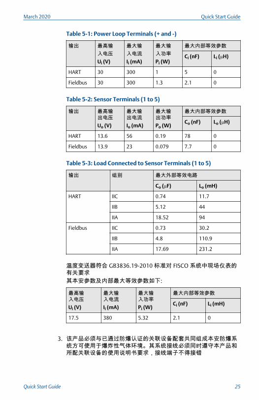
Table 5-1: Power Loop Terminals (+ and -)
输出 最高输入电压Ui (V)
最大输入电流Ii (mA)
最大输入功率Pi (W)
最大内部等效参数
Ci (nF) Li (µH)
HART 30 300 1 5 0
Fieldbus 30 300 1.3 2.1 0
Table 5-2: Sensor Terminals (1 to 5)
输出 最高输出电压Uo (V)
最大输出电流Io (mA)
最大输出功率Po (W)
最大内部等效参数
Co (nF) Lo (µH)
HART 13.6 56 0.19 78 0
Fieldbus 13.9 23 0.079 7.7 0
Table 5-3: Load Connected to Sensor Terminals (1 to 5)
输出 组别 最大外部等效电路
Co (µF) Lo (mH)
HART IIC 0.74 11.7
IIB 5.12 44
IIA 18.52 94
Fieldbus IIC 0.73 30.2
IIB 4.8 110.9
IIA 17.69 231.2
温度变送器符合 GB3836.19-2010 标准对 FISCO 系统中现场仪表的有关要求其本安参数及内部最大等效参数如下:
最高输入电压Ui (V)
最大输入电流Ii (mA)
最大输入功率Pi (W)
最大内部等效参数
Ci (nF) Li (mH)
17.5 380 5.32 2.1 0
3. 该产品必须与已通过防爆认证的关联设备配套共同组成本安防爆系统方可使用于爆炸性气体环境。其系统接线必须同时遵守本产品和所配关联设备的使用说明书要求,接线端子不得接错
March 2020 Quick Start Guide
Quick Start Guide 25
4. 该产品与关联设备的连接电缆应为带绝缘护套的屏蔽电缆,其屏蔽层应在安全场所接地
5. 用户不得自行更换该产品的零部件,应会同产品制造商共同解决运行中出现的故障,以杜绝损坏现象的发生
6. 产品的安装、使用和维护应同时遵守产品使用说明书、GB3836.13-2013“爆炸性环境 第 13 部分:设备的修理、检修、修复和改造”、GB3836.15-2000“爆炸性气体环境用电气设备 第 15 部分:危险场所电气安装(煤矿除外)”、GB3836.16-2006“爆炸性气体环境用电气设备 第 16 部分:电气装置的检查和维护(煤矿除外)”、GB3836.18-2010“爆炸性环境 第 18 部分:本质安全系统”和GB50257-2014“电气装置安装工程爆炸和火灾危险环境电力装置施工及验收规范”的有关规定
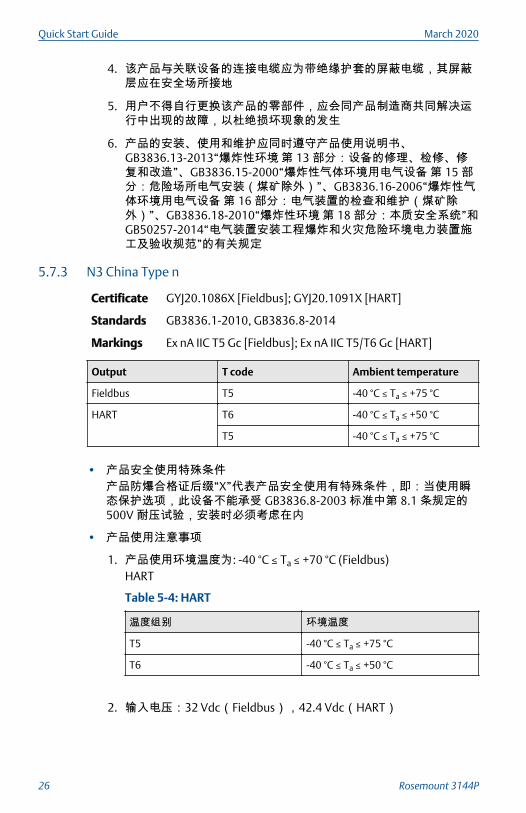
5.7.3 N3 China Type n
Certificate GYJ20.1086X [Fieldbus]; GYJ20.1091X [HART]
Standards GB3836.1-2010, GB3836.8-2014
Markings Ex nA IIC T5 Gc [Fieldbus]; Ex nA IIC T5/T6 Gc [HART]
Output T code Ambient temperature
Fieldbus T5 -40 °C ≤ Ta ≤ +75 °C
HART T6 -40 °C ≤ Ta ≤ +50 °C
T5 -40 °C ≤ Ta ≤ +75 °C
• 产品安全使用特殊条件产品防爆合格证后缀“X”代表产品安全使用有特殊条件,即:当使用瞬态保护选项,此设备不能承受 GB3836.8-2003 标准中第 8.1 条规定的500V 耐压试验,安装时必须考虑在内
• 产品使用注意事项
1. 产品使用环境温度为: -40 °C ≤ Ta ≤ +70 °C (Fieldbus)HART
Table 5-4: HART
温度组别 环境温度
T5 -40 °C ≤ Ta ≤ +75 °C
T6 -40 °C ≤ Ta ≤ +50 °C
2. 输入电压:32 Vdc(Fieldbus),42.4 Vdc(HART)
Quick Start Guide March 2020
26 Rosemount 3144P
3. 现场安装时,电缆引入口须选用经国家指定的防爆检验机构检验认可的 Exe 或 Exn 型、螺纹规格为 14NPT 的电缆引入装置或封堵件,冗余电缆引入口须用封堵件有效密封
4. 现场安装时,电缆引入口须选用经国家指定的防爆检验机构检验认可的 Exe 或 Exn 型、螺纹规格为 14NPT 的电缆引入装置或封堵件,冗余电缆引入口须用封堵件有效密封
5. 安装现场确认无可燃性气体存在时方可维修
6. 用户不得自行更换该产品的零部件,应会同产品制造商共同解决运行中出现的故障,以杜绝损坏现象的发生
7. 产品的安装、使用和维护应同时遵守产品使用说明书、GB3836.13-2013 “爆炸性环境 第 13 部分:设备的修理、检修、修复和改造”、GB3836.15-2000 “爆炸性气体环境用电气设备 第 15 部分:危险场所电气安装(煤矿除外)”、GB3836.16-2006 “爆炸性气体环境用电气设备 第 16 部分:电气装置的检查和维护(煤矿除外)”和 GB50257-2014“电气装置安装工程爆炸和火灾危险环境电力装置施工及验收规范”的有关规定。
5.8 EAC - Belarus, Kazakhstan, Russia5.8.1 EM Technical Regulation Customs Union (EAC) Flameproof
Standards GOST 31610.0-2014, GOST IEC 60079-1-2013
Markings 1Ex db IIC T6…T1 Gb X, T6(-50 °C ≤ Ta ≤ +40 °C), T5…T1(-50 °C≤ Ta ≤ +60 °C)See Process temperature limits for process temperatures.
Special Condition for Safe Use (X):
1. Non-standard paint options may cause risk of electrostatic discharge.Avoid installations that cause electrostatic build-up on paintedsurfaces and only clean the painted surfaces with a damp cloth. Ifpaint is ordered through a special option code, contact themanufacturer for more information.
5.8.2 IM Technical Regulation Customs Union (EAC) Intrinsic Safety
Standards GOST 31610.0-2014, GOST IEC 60079-11-2014
Markings [HART]: 0Ex ia IIC T5, T6 Ga X, T6(-60 °C ≤ Ta ≤ +50 °C),T5(-60 °C ≤ Ta ≤ +75 °C);[Fieldbus/PROFIBUS]: 0Ex ia IIC T4 Ga X, T4(-60 °C ≤ Ta ≤ +60 °C
See Table 5-9 for entity parameters.
Special Conditions for Safe Use (X):
1. When fitted with the transient terminal options, the apparatus is notcapable of withstanding the 500 V electrical strength test as defined
March 2020 Quick Start Guide
Quick Start Guide 27
in Clause 6.3.13 of GOST 31610.11-2014. This must be taken intoaccount during installation.
2. The enclosure may be made from aluminum alloy with a protectivepolyurethane paint finish; however, care should be taken to protect itfrom impact or abrasion when located in Zone 0.
5.8.3 KM Technical Regulation Customs Union (EAC) Flameproof, IntrinsicSafety, and Dust
Standards GOST 31610.0-2014, GOST IEC 60079-1-2013, GOST IEC60079-11-2014, GOST IEC 60079-31-2013
Markings Ex tb IIIC T130 °C Db X (-40 °C ≤ Ta ≤ +70 °C), IP 66 in additionto markings listed for EM and IM above.
Special Condition for Safe Use (X):
1. See certificate for special conditions.
5.9 Japan5.9.1 E4 TIIS Flameproof
Certificate TC21038, TC21039
Markings Ex d IIC T5 (-20 °C ≤ Ta ≤ +60 °C)
Certificate TC16127, TC16128, TC16129, TC16130
Markings Ex d IIB T4 (-20 °C ≤ Ta ≤ +55 °C)
5.10 Korea5.10.1 EP Korea Flameproof
Certificate 10-KB4BO-0011X
Markings Ex d IIC T6/T5; T6(-40 °C ≤ Tamb ≤ +70 °C), T5(-40 °C ≤ Tamb ≤+80 °C)
Special Condition for Safe Use (X):
1. See certificate for special conditions.
5.10.2 IP Korea Intrinsic Safety
Certificate 09-KB4BO-0028X
Markings Ex ia IIC T6/T5; T6(-60 °C ≤ Tamb ≤ +50 °C), T5(-60 °C ≤ Tamb ≤+75 °C)
Quick Start Guide March 2020
28 Rosemount 3144P
Special Condition for Safe Use (X):
1. See certificate for special conditions.
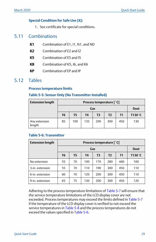
5.11 Combinations
K1 Combination of E1, I1, N1, and ND
K2 Combination of E2 and I2
K5 Combination of E5 and I5
KB Combination of K5, I6, and K6
KP Combination of EP and IP
5.12 Tables
Process temperature limits
Table 5-5: Sensor Only (No Transmitter Installed)
Extension length Process temperature [˚C]
Gas Dust
T6 T5 T4 T3 T2 T1 T130 °C
Any extensionlength
85 100 135 200 300 450 130
Table 5-6: Transmitter
Extension length Process temperature [˚C]
Gas Dust
T6 T5 T4 T3 T2 T1 T130 °C
No extension 55 70 100 170 280 440 100
3-in. extension 55 70 110 190 300 450 110
6-in. extension 60 70 120 200 300 450 110
9-in. extension 65 75 130 200 300 450 120
Adhering to the process temperature limitations of Table 5-7 will ensure thatthe service temperature limitations of the LCD display cover are notexceeded. Process temperatures may exceed the limits defined in Table 5-7if the temperature of the LCD display cover is verified to not exceed theservice temperatures in Table 5-8 and the process temperatures do notexceed the values specified in Table 5-6.
March 2020 Quick Start Guide
Quick Start Guide 29

Table 5-7: Transmitter with LCD Display Cover
Extension length Process temperature [˚C]
Gas Dust
T6 T5 T4...T1 T130 °C
No extension 55 70 95 95
3-in. extension 55 70 100 100
6-in. extension 60 70 100 100
9-in. extension 65 75 110 110
Table 5-8: Transmitter with LCD Display Cover
Extension length Service temperature [˚C]
Gas Dust
T6 T5 T4...T1 T130 °C
Any extension length 65 75 95 95
Entity parameters
Table 5-9: Entity Parameters
Parameters HART Fieldbus/PROFIBUS
FISCO
Voltage Ui (V) 30 30 17.5
Current Ii (mA) 300 300 380
Power Pi (W) 1 1.3 5.32
Capacitance Ci (nF) 5 2.1 2.1
Inductance Li (mH) 0 0 0
5.13 Additional certifications
SBS American Bureau of Shipping (ABS) Type Approval
Certificate 16-HS1488352-PDA
Intended use Measurement of temperature for marine and offshoreapplications
SBV Bureau Veritas (BV) Type Approval
Certificate 23154
Quick Start Guide March 2020
30 Rosemount 3144P
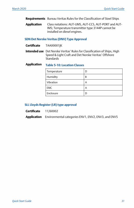
Requirements Bureau Veritas Rules for the Classification of Steel Ships
Application Class notations: AUT-UMS, AUT-CCS, AUT-PORT and AUT-IMS; Temperature transmitter type 3144P cannot beinstalled on diesel engines.
SDN Det Norske Veritas (DNV) Type Approval
Certificate TAA00001JK
Intended use Det Norske Veritas’ Rules for Classification of Ships, HighSpeed & Light Craft and Det Norske Veritas’ OffshoreStandards
Application Table 5-10: Location Classes
Temperature D
Humidity B
Vibration A
EMC A
Enclosure D
SLL Lloyds Register (LR) type approval
Certificate 11/60002
Application Environmental categories ENV1, ENV2, ENV3, and ENV5
March 2020 Quick Start Guide
Quick Start Guide 31
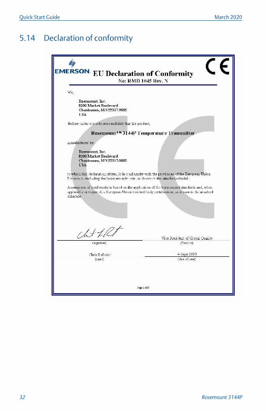
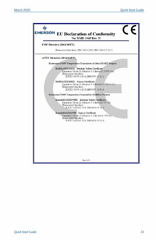
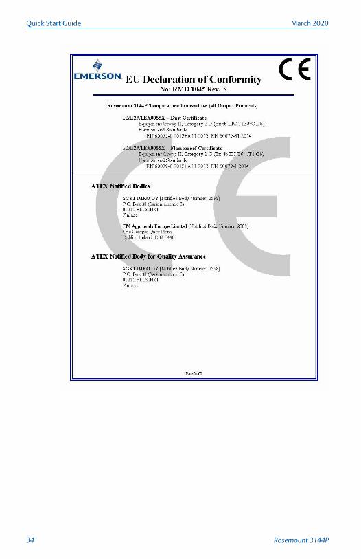
5.14 Declaration of conformity
Quick Start Guide March 2020
32 Rosemount 3144P
March 2020 Quick Start Guide
Quick Start Guide 33
Quick Start Guide March 2020
34 Rosemount 3144P
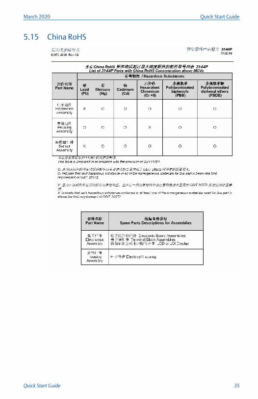
5.15 China RoHS
March 2020 Quick Start Guide
Quick Start Guide 35

*00825-0100-4834*Quick Start Guide
00825-0100-4834, Rev. FAMarch 2020
Global HeadquartersEmerson Automation Solutions6021 Innovation Blvd.Shakopee, MN 55379, USA
+1 800 999 9307 or +1 952 906 8888
+1 952 204 8889
North America Regional OfficeEmerson Automation Solutions8200 Market Blvd.Chanhassen, MN 55317, USA
+1 800 999 9307 or +1 952 906 8888
+1 952 204 8889
Latin America Regional OfficeEmerson Automation Solutions1300 Concord Terrace, Suite 400Sunrise, FL 33323, USA
+1 954 846 5030
+1 954 846 5121
Europe Regional OfficeEmerson Automation Solutions EuropeGmbHNeuhofstrasse 19a P.O. Box 1046CH 6340 BaarSwitzerland
+41 (0) 41 768 6111
+41 (0) 41 768 6300
Asia Pacific Regional OfficeEmerson Automation Solutions1 Pandan CrescentSingapore 128461
+65 6777 8211
+65 6777 0947
Middle East and Africa Regional OfficeEmerson Automation SolutionsEmerson FZE P.O. Box 17033Jebel Ali Free Zone - South 2Dubai, United Arab Emirates
+971 4 8118100
+971 4 8865465
Linkedin.com/company/Emerson-Automation-Solutions
Twitter.com/Rosemount_News
Facebook.com/Rosemount
Youtube.com/user/RosemountMeasurement
©2020 Emerson. All rights reserved.
Emerson Terms and Conditions of Sale areavailable upon request. The Emerson logo is atrademark and service mark of Emerson ElectricCo. Rosemount is a mark of one of the Emersonfamily of companies. All other marks are theproperty of their respective owners.