Embed Size (px)
Citation preview
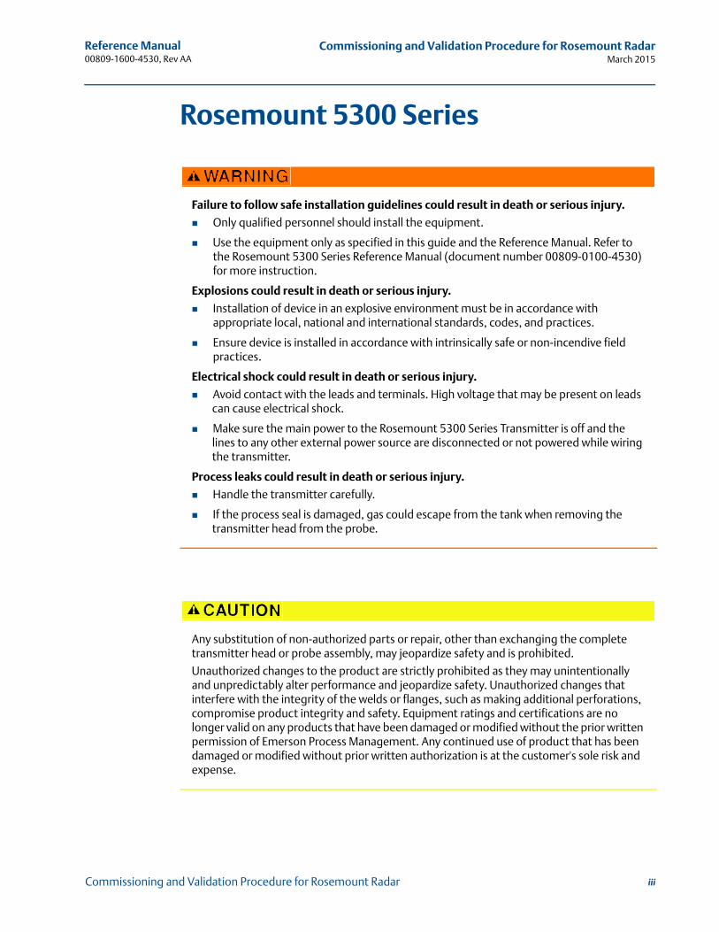
Reference Manual00809-1600-4530, Rev AA
March 2015
Rosemount 5300 SeriesCommissioning and Validation Procedures for Rosemount Radar

iii
Reference Manual 00809-1600-4530, Rev AA
Commissioning and Validation Procedure for Rosemount RadarMarch 2015
Commissioning and Validation Procedure for Rosemount Radar
Rosemount 5300 Series
Failure to follow safe installation guidelines could result in death or serious injury.
Only qualified personnel should install the equipment.
Use the equipment only as specified in this guide and the Reference Manual. Refer to the Rosemount 5300 Series Reference Manual (document number 00809-0100-4530) for more instruction.
Explosions could result in death or serious injury.
Installation of device in an explosive environment must be in accordance with appropriate local, national and international standards, codes, and practices.
Ensure device is installed in accordance with intrinsically safe or non-incendive field practices.
Electrical shock could result in death or serious injury.
Avoid contact with the leads and terminals. High voltage that may be present on leads can cause electrical shock.
Make sure the main power to the Rosemount 5300 Series Transmitter is off and the lines to any other external power source are disconnected or not powered while wiring the transmitter.
Process leaks could result in death or serious injury.
Handle the transmitter carefully.
If the process seal is damaged, gas could escape from the tank when removing the transmitter head from the probe.
Any substitution of non-authorized parts or repair, other than exchanging the complete transmitter head or probe assembly, may jeopardize safety and is prohibited.
Unauthorized changes to the product are strictly prohibited as they may unintentionally and unpredictably alter performance and jeopardize safety. Unauthorized changes that interfere with the integrity of the welds or flanges, such as making additional perforations, compromise product integrity and safety. Equipment ratings and certifications are no longer valid on any products that have been damaged or modified without the prior written permission of Emerson Process Management. Any continued use of product that has been damaged or modified without prior written authorization is at the customer's sole risk and expense.

iv
Reference Manual 00809-1600-4530, Rev AA
Commissioning and Validation Procedure for Rosemount RadarMarch 2015
Commissioning and Validation Procedure for Rosemount Radar
Reference Manual 00809-1600-4530, Rev AA
ContentsMarch 2015
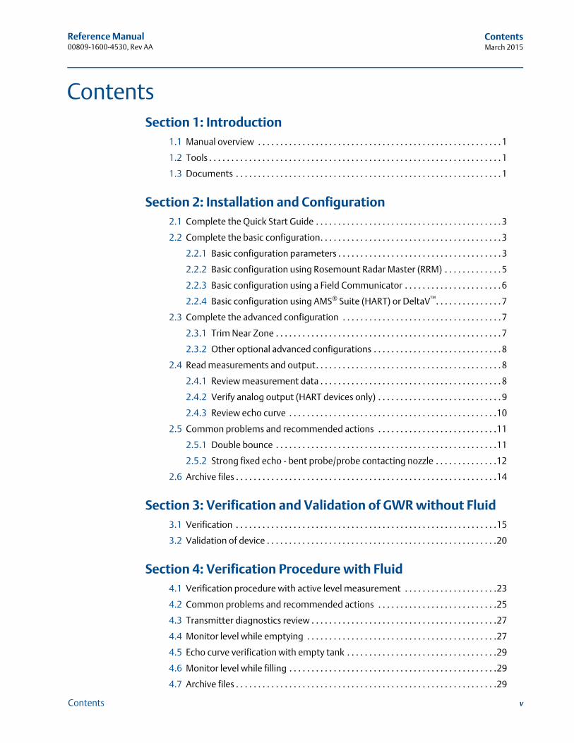
Contents
1Section 1: Introduction1.1 Manual overview . . . . . . . . . . . . . . . . . . . . . . . . . . . . . . . . . . . . . . . . . . . . . . . . . . . . . . . 1
1.2 Tools . . . . . . . . . . . . . . . . . . . . . . . . . . . . . . . . . . . . . . . . . . . . . . . . . . . . . . . . . . . . . . . . . . 1
1.3 Documents . . . . . . . . . . . . . . . . . . . . . . . . . . . . . . . . . . . . . . . . . . . . . . . . . . . . . . . . . . . . 1
2Section 2: Installation and Configuration2.1 Complete the Quick Start Guide . . . . . . . . . . . . . . . . . . . . . . . . . . . . . . . . . . . . . . . . . . 3
2.2 Complete the basic configuration. . . . . . . . . . . . . . . . . . . . . . . . . . . . . . . . . . . . . . . . . 3
2.2.1 Basic configuration parameters . . . . . . . . . . . . . . . . . . . . . . . . . . . . . . . . . . . . . 3
2.2.2 Basic configuration using Rosemount Radar Master (RRM) . . . . . . . . . . . . . 5
2.2.3 Basic configuration using a Field Communicator . . . . . . . . . . . . . . . . . . . . . . 6
2.2.4 Basic configuration using AMS® Suite (HART) or DeltaV™. . . . . . . . . . . . . . . 7
2.3 Complete the advanced configuration . . . . . . . . . . . . . . . . . . . . . . . . . . . . . . . . . . . . 7
2.3.1 Trim Near Zone . . . . . . . . . . . . . . . . . . . . . . . . . . . . . . . . . . . . . . . . . . . . . . . . . . . 7
2.3.2 Other optional advanced configurations . . . . . . . . . . . . . . . . . . . . . . . . . . . . . 8
2.4 Read measurements and output. . . . . . . . . . . . . . . . . . . . . . . . . . . . . . . . . . . . . . . . . . 8
2.4.1 Review measurement data . . . . . . . . . . . . . . . . . . . . . . . . . . . . . . . . . . . . . . . . . 8
2.4.2 Verify analog output (HART devices only) . . . . . . . . . . . . . . . . . . . . . . . . . . . . 9
2.4.3 Review echo curve . . . . . . . . . . . . . . . . . . . . . . . . . . . . . . . . . . . . . . . . . . . . . . .10
2.5 Common problems and recommended actions . . . . . . . . . . . . . . . . . . . . . . . . . . .11
2.5.1 Double bounce . . . . . . . . . . . . . . . . . . . . . . . . . . . . . . . . . . . . . . . . . . . . . . . . . .11
2.5.2 Strong fixed echo - bent probe/probe contacting nozzle . . . . . . . . . . . . . .12
2.6 Archive files . . . . . . . . . . . . . . . . . . . . . . . . . . . . . . . . . . . . . . . . . . . . . . . . . . . . . . . . . . .14
3Section 3: Verification and Validation of GWR without Fluid3.1 Verification . . . . . . . . . . . . . . . . . . . . . . . . . . . . . . . . . . . . . . . . . . . . . . . . . . . . . . . . . . .15
3.2 Validation of device . . . . . . . . . . . . . . . . . . . . . . . . . . . . . . . . . . . . . . . . . . . . . . . . . . . .20
4Section 4: Verification Procedure with Fluid4.1 Verification procedure with active level measurement . . . . . . . . . . . . . . . . . . . . .23
4.2 Common problems and recommended actions . . . . . . . . . . . . . . . . . . . . . . . . . . .25
4.3 Transmitter diagnostics review . . . . . . . . . . . . . . . . . . . . . . . . . . . . . . . . . . . . . . . . . .27
4.4 Monitor level while emptying . . . . . . . . . . . . . . . . . . . . . . . . . . . . . . . . . . . . . . . . . . .27
4.5 Echo curve verification with empty tank . . . . . . . . . . . . . . . . . . . . . . . . . . . . . . . . . .29
4.6 Monitor level while filling . . . . . . . . . . . . . . . . . . . . . . . . . . . . . . . . . . . . . . . . . . . . . . .29
4.7 Archive files . . . . . . . . . . . . . . . . . . . . . . . . . . . . . . . . . . . . . . . . . . . . . . . . . . . . . . . . . . .29
vContents
Reference Manual 00809-1600-4530, Rev AA
ContentsMarch 2015
4.7.1 Other validation suggestions . . . . . . . . . . . . . . . . . . . . . . . . . . . . . . . . . . . . . .30
5Section 5: Additional Options5.1 Introduction . . . . . . . . . . . . . . . . . . . . . . . . . . . . . . . . . . . . . . . . . . . . . . . . . . . . . . . . . .31
5.2 Signal Quality Metrics (SQM) . . . . . . . . . . . . . . . . . . . . . . . . . . . . . . . . . . . . . . . . . . . .31
5.3 Verification reflector . . . . . . . . . . . . . . . . . . . . . . . . . . . . . . . . . . . . . . . . . . . . . . . . . . .32
5.3.1 High level supervision . . . . . . . . . . . . . . . . . . . . . . . . . . . . . . . . . . . . . . . . . . . .33
5.3.2 Limitations for verification reflector . . . . . . . . . . . . . . . . . . . . . . . . . . . . . . . .33
6Section 6: SIS Installations6.1 Installation in SIS applications . . . . . . . . . . . . . . . . . . . . . . . . . . . . . . . . . . . . . . . . . . .35
6.2 Configuring in SIS applications . . . . . . . . . . . . . . . . . . . . . . . . . . . . . . . . . . . . . . . . . .36
6.3 SIS operation and maintenance. . . . . . . . . . . . . . . . . . . . . . . . . . . . . . . . . . . . . . . . . .37
6.3.1 Proof test . . . . . . . . . . . . . . . . . . . . . . . . . . . . . . . . . . . . . . . . . . . . . . . . . . . . . . .37
AAppendix A: Commissioning ChecklistA.1 Plant information . . . . . . . . . . . . . . . . . . . . . . . . . . . . . . . . . . . . . . . . . . . . . . . . . . . . . .41
A.1.1 General information . . . . . . . . . . . . . . . . . . . . . . . . . . . . . . . . . . . . . . . . . . . . . .41
A.1.2 Tank information . . . . . . . . . . . . . . . . . . . . . . . . . . . . . . . . . . . . . . . . . . . . . . . .42
A.1.3 Mechanical installation . . . . . . . . . . . . . . . . . . . . . . . . . . . . . . . . . . . . . . . . . . .43
A.1.4 Electrical installation . . . . . . . . . . . . . . . . . . . . . . . . . . . . . . . . . . . . . . . . . . . . .44
A.1.5 Is the product’s Ex classification in accordance with requirements?. . . . .45
A.2 Echo tuning . . . . . . . . . . . . . . . . . . . . . . . . . . . . . . . . . . . . . . . . . . . . . . . . . . . . . . . . . . .46
A.3 Backups and plots . . . . . . . . . . . . . . . . . . . . . . . . . . . . . . . . . . . . . . . . . . . . . . . . . . . . .46
A.4 GWR radar verification in chambers . . . . . . . . . . . . . . . . . . . . . . . . . . . . . . . . . . . . . .47
vi Contents
Reference Manual 00809-1600-4530, Rev AA
Section 1: IntroductionMarch 2015
1Introduction
Section 1 Introduction
1.1 Manual overview
This manual provides commissioning, verification, and validation information for the Rosemount 5300 Series Radar Transmitters.
This manual is intended to be used with the Rosemount 5300 Series Reference Manual (document number 00809-0100-4530).
1.2 Tools
The following tools and documents are recommended to use during the installation and commissioning procedures:
Field Communicator 475/laptop with Rosemount Radar Master (RRM) or AMS® Device Manager
HART® modem/FOUNDATION™ fieldbus modem
Multimeter
Screw driver, Phillips 2 mm or flat head 6 mm (for wire terminals)
Screw driver, flat head 8 mm (for external ground screw)
Adjustable spanner (for cable glands)
Wrench, 54 mm (to install or remove the transmitter head)
Allen key, 3 mm, 4 mm, and 5 mm (to loose and fix the weight)
Allen key, 2 mm (to secure the coaxial probe)
Hack saw (to shorten the rigid probes)
Heavy duty nipper (to shorten the flexible probes)
1.3 Documents
Rosemount 5300 Series Superior Performance Guided Wave Radar Level and Interface Transmitter Quick Installation Guide(document number 00825-0100-4530)
Rosemount 5300 Series Superior Performance Guided Wave Radar Reference Manual(document number 00809-0100-4530)
Rosemount 5300 Series - Using Guided Waver Radar for Level in High Pressure Steam Applications Technical Note(document number 00840-0100-4530)

Reference Manual 00809-1600-4530, Rev AA
Section 1: IntroductionMarch 2015
2 Introduction
Reference Manual 00809-1600-4530, Rev AA
Section 2: Installation & configurationMarch 2015
Section 2 Installation and Configuration
Complete the Quick Start Guide . . . . . . . . . . . . . . . . . . . . . . . . . . . . . . . . . . . . . . . . . . . . . . page 3Complete the basic configuration . . . . . . . . . . . . . . . . . . . . . . . . . . . . . . . . . . . . . . . . . . . . . page 3Complete the advanced configuration . . . . . . . . . . . . . . . . . . . . . . . . . . . . . . . . . . . . . . . . . page 7Read measurements and output . . . . . . . . . . . . . . . . . . . . . . . . . . . . . . . . . . . . . . . . . . . . . . page 8Common problems and recommended actions . . . . . . . . . . . . . . . . . . . . . . . . . . . . . . . . . page 11Archive files . . . . . . . . . . . . . . . . . . . . . . . . . . . . . . . . . . . . . . . . . . . . . . . . . . . . . . . . . . . . . . . . page 14
2.1 Complete the Quick Start Guide
Mount the transmitter, connect wiring, and power up as described in the 5300 Quick Start Guide (document number 00825-0100-4530).
2.2 Complete the basic configuration
2.2.1 Basic configuration parameters HART®/FOUNDATION™ fieldbus address
Device tag
Measurement units
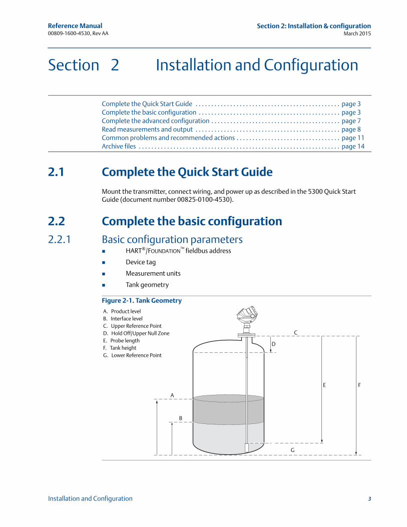
Tank geometry
Figure 2-1. Tank Geometry
A
B
C
D
E F
G
A. Product levelB. Interface levelC. Upper Reference Point D. Hold Off/Upper Null ZoneE. Probe length F. Tank height G. Lower Reference Point
3Installation and Configuration
Reference Manual 00809-1600-4530, Rev AA
Section 2: Installation & configurationMarch 2015
Probe type
Hold Off/Upper Null Zone. This parameter should only be changed if there are disturbing objects close to the probe, e.g. nozzle disturbances. No valid measurements are possible above the Hold Off Distance.
Measurement mode
Rapid level changes
Dielectric constant
Volume configuration. For volume calculations, you can select one of the standard tank shapes or the strapping option. Select None if volume calculation is not used.
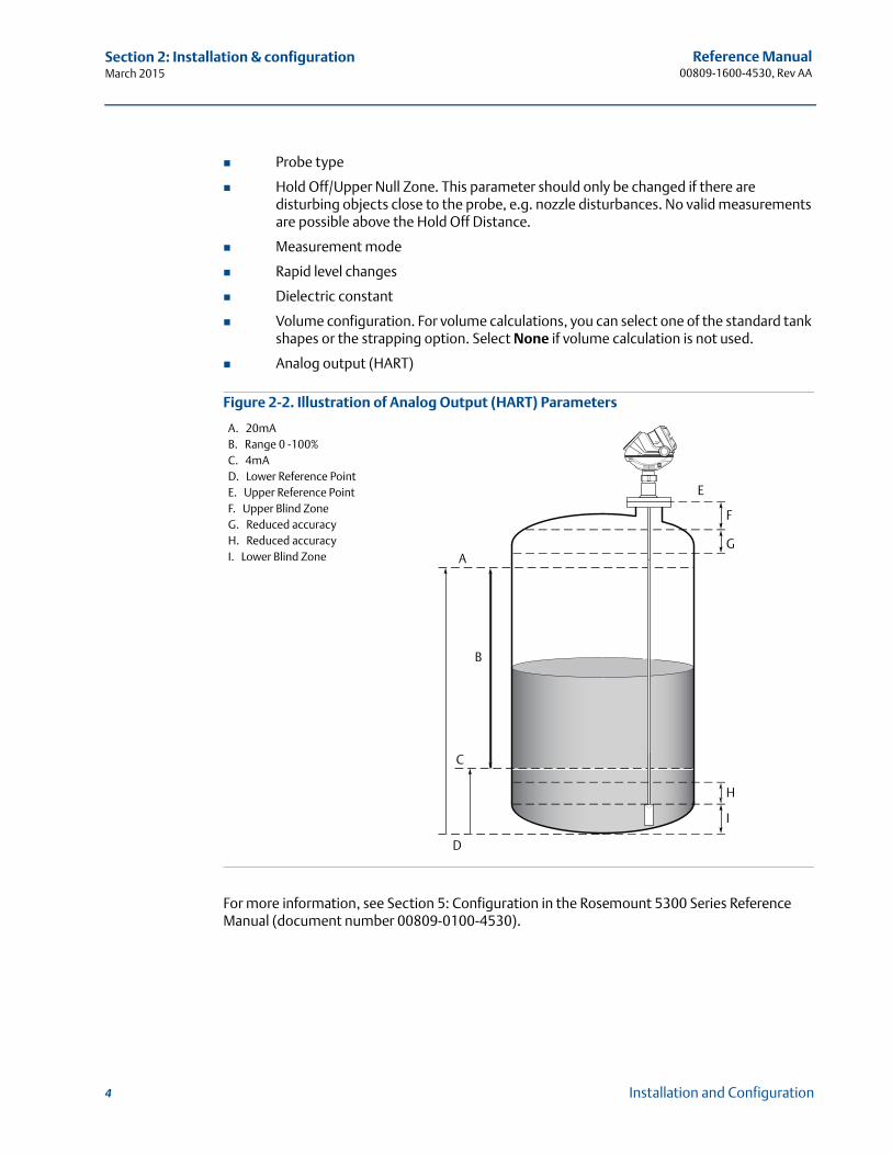
Analog output (HART)
Figure 2-2. Illustration of Analog Output (HART) Parameters
For more information, see Section 5: Configuration in the Rosemount 5300 Series Reference Manual (document number 00809-0100-4530).
A
B
C
D
F
E
G
H
I
A. 20mAB. Range 0 -100%C. 4mAD. Lower Reference PointE. Upper Reference PointF. Upper Blind ZoneG. Reduced accuracy H. Reduced accuracyI. Lower Blind Zone
4 Installation and Configuration
Reference Manual 00809-1600-4530, Rev AA
Section 2: Installation & configurationMarch 2015
AI block (FOUNDATION fieldbus). A minimum of four parameters are required to configure the AI Block.
Channel - Corresponds to the desired sensor measurement
L_TYPE - Defines the relationship to the desired output of the AI Block. Direct or indirect root.
XD_SCALE - Include 0%, 100%, and engineering units
OUT_SCALE - Include 0%, 100%, and engineering units
For more information, see Section 5.9 FOUNDATION fieldbus Overview and Appendix E Level Transducer block in the Rosemount 5300 Series Reference Manual (document number 00809-0100-4530).
2.2.2 Basic configuration using Rosemount Radar Master (RRM)
1. Start the Guided Setup.
2. Start the Configuration Wizard.
3. Select the Device specific setup to see if any additional configuration is needed.
4. Restart the Device.
5. Run Verify level.
6. Select Archive Device to make a complete backup of the device, including several logs, and echo curves.
7. View live values from the device.
For more information, see Section 5.6 in the Rosemount 5300 Series Reference Manual (document number 00809-0100-4530).
5Installation and Configuration
Reference Manual 00809-1600-4530, Rev AA
Section 2: Installation & configurationMarch 2015
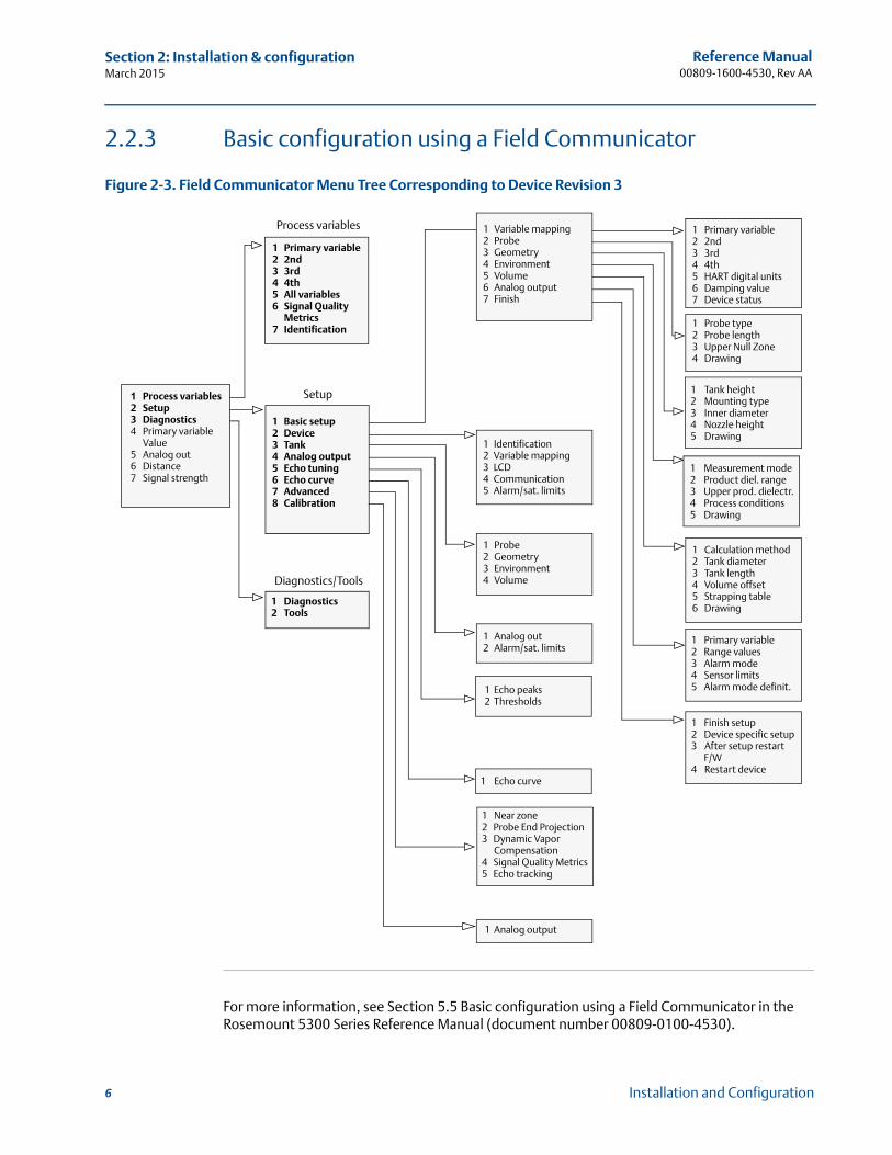
2.2.3 Basic configuration using a Field Communicator
Figure 2-3. Field Communicator Menu Tree Corresponding to Device Revision 3
For more information, see Section 5.5 Basic configuration using a Field Communicator in the Rosemount 5300 Series Reference Manual (document number 00809-0100-4530).
Process variables
1 Process variables2 Setup3 Diagnostics4 Primary variable
Value5 Analog out6 Distance7 Signal strength
1 Primary variable2 2nd3 3rd4 4th5 All variables6 Signal Quality
Metrics7 Identification
1 Basic setup2 Device3 Tank4 Analog output5 Echo tuning6 Echo curve7 Advanced8 Calibration
1 Diagnostics2 Tools
1 Variable mapping2 Probe3 Geometry4 Environment5 Volume6 Analog output7 Finish
1 Identification2 Variable mapping3 LCD4 Communication5 Alarm/sat. limits
1 Probe2 Geometry3 Environment4 Volume
1 Analog out2 Alarm/sat. limits
1 Echo peaks2 Thresholds
1 Echo curve
1 Near zone2 Probe End Projection3 Dynamic Vapor
Compensation4 Signal Quality Metrics5 Echo tracking
Setup
Diagnostics/Tools
1 Primary variable2 2nd3 3rd4 4th5 HART digital units6 Damping value7 Device status
1 Probe type2 Probe length3 Upper Null Zone4 Drawing
1 Tank height2 Mounting type3 Inner diameter4 Nozzle height5 Drawing
1 Measurement mode2 Product diel. range3 Upper prod. dielectr.4 Process conditions5 Drawing
1 Calculation method2 Tank diameter3 Tank length4 Volume offset5 Strapping table6 Drawing
1 Primary variable2 Range values3 Alarm mode4 Sensor limits5 Alarm mode definit.
1 Finish setup2 Device specific setup3 After setup restart
F/W4 Restart device
1 Analog output
6 Installation and Configuration
Reference Manual 00809-1600-4530, Rev AA
Section 2: Installation & configurationMarch 2015
2.2.4 Basic configuration using AMS® Suite (HART) or DeltaV™
The Rosemount 5300 Series can also be configured using AMS Suite or DeltaV.
For more information, see Section 5.7 Basic Configuration Using AMS Suite (HART) in the Rosemount 5300 Series Reference Manual (document number 00809-0100-4530).
2.3 Complete the advanced configuration
For more information, see Appendix C.3: Advanced Configuration in the Rosemount 5300 Series Reference Manual (document number 00809-0100-4530).
2.3.1 Trim Near Zone
NoteTrim Near Zone should not be performed on Dynamic Vapor Compensation or Coaxial probes.
Use Trim Near Zone when mounted in a nozzle, chamber, or still-pipe. An exception is narrow nozzles as defined below:
2 in. (50 mm) < Nozzle height < 12 in. (300 mm)
Nozzle diameter < 2 in. (50 mm) for all single probes(Nozzle diameter < 3 in. (75 mm) for 13 mm single rigid)
To complete the Trim Near Zone function:
1. Make sure the product level is below the near zone region (3.3 ft [1 m] from the flange face).
2. Select Trim Near Zone and follow the instructions.
NoteTrim Near Zone should not be completed when the unit is installed in an empty metal tank. A small amount of fluid should be added before the Trim Near Zone step is completed.
7Installation and Configuration
Reference Manual 00809-1600-4530, Rev AA
Section 2: Installation & configurationMarch 2015
8 Installation and Configuration
2.3.2 Other optional advanced configurations
Other functions that may be required can be found in Appendix C of the reference manual. Some of these may only be needed in certain conditions. This includes settings for:
Hold Off Distance/Upper Null Zone which defines how close to the upper reference point a level value is accepted. This will block out false targets and measurements in this area.
Threshold settings which determine the minimum signal amplitude limits of key parameters such as the surface echo, interface echo, reference peak and end of probe peak.
Probe End Projection is used to support the surface measurement in low dielectric materials and when the surface is close to the end of the probe.
Echo tracking may be needed to enhance the measurement tracking capabilities in some conditions such as rapid level changes or excessive turbulence
Dielectric constant settings may need adjustment in interface or saturated steam applications.
Dynamic Vapor Compensation is used in saturated steam applications with a probe that includes a steam compensation reflector.
Signal Quality Metrics are used to indicate the integrity of the surface signal compared to the noise. It could be used to detect excessive coating on the probe or the presence of some heavy foams.
2.4 Read measurements and output
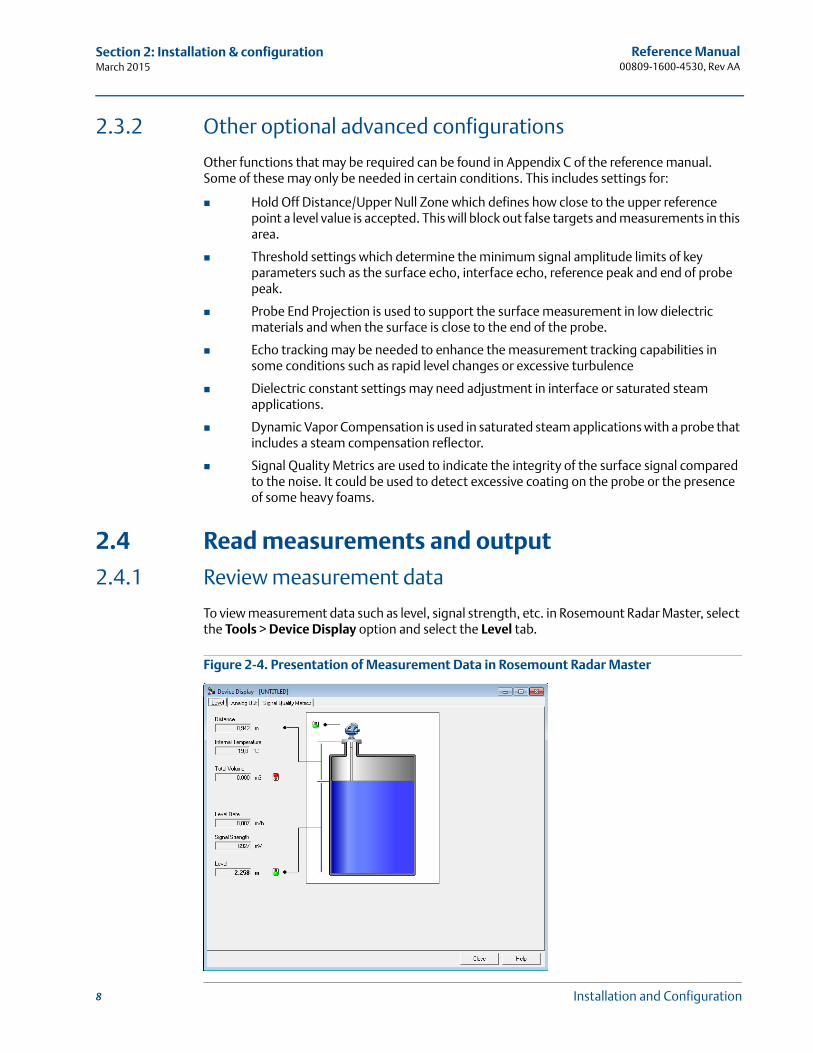
2.4.1 Review measurement data
To view measurement data such as level, signal strength, etc. in Rosemount Radar Master, select the Tools > Device Display option and select the Level tab.
Figure 2-4. Presentation of Measurement Data in Rosemount Radar Master
Reference Manual 00809-1600-4530, Rev AA
Section 2: Installation & configurationMarch 2015
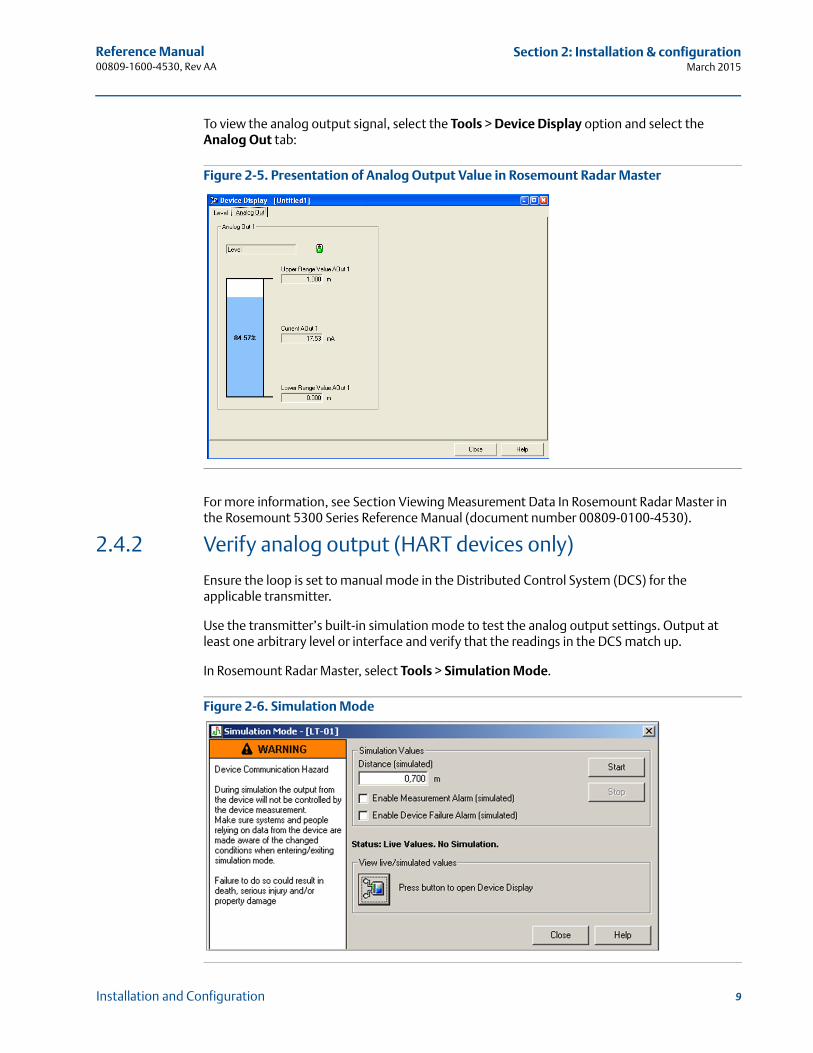
To view the analog output signal, select the Tools > Device Display option and select the Analog Out tab:
Figure 2-5. Presentation of Analog Output Value in Rosemount Radar Master
For more information, see Section Viewing Measurement Data In Rosemount Radar Master in the Rosemount 5300 Series Reference Manual (document number 00809-0100-4530).
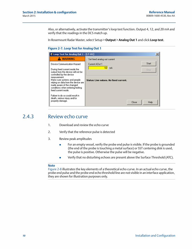
2.4.2 Verify analog output (HART devices only)
Ensure the loop is set to manual mode in the Distributed Control System (DCS) for the applicable transmitter.
Use the transmitter’s built-in simulation mode to test the analog output settings. Output at least one arbitrary level or interface and verify that the readings in the DCS match up.
In Rosemount Radar Master, select Tools > Simulation Mode.
Figure 2-6. Simulation Mode
9Installation and Configuration
Reference Manual 00809-1600-4530, Rev AA
Section 2: Installation & configurationMarch 2015
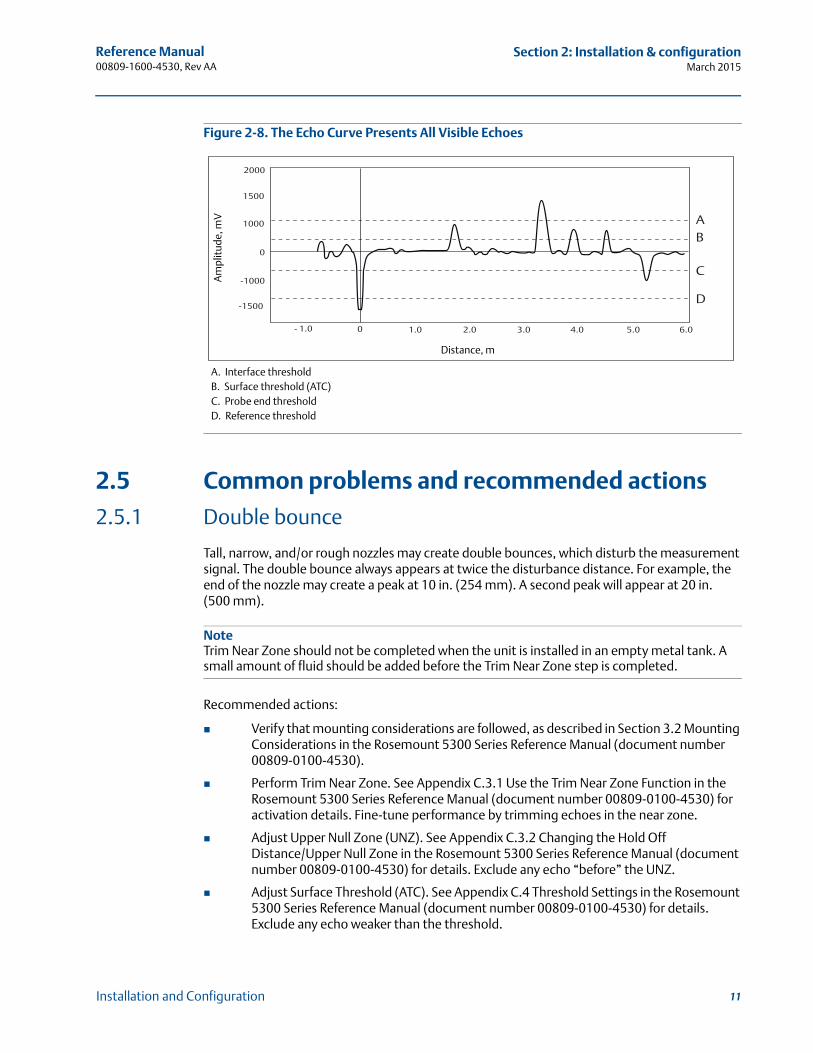
Also, or alternatively, activate the transmitter’s loop test function. Output 4, 12, and 20 mA and verify that the readings in the DCS match up.
In Rosemount Radar Master, select Setup > Output > Analog Out 1 and click Loop test.
Figure 2-7. Loop Test for Analog Out 1
2.4.3 Review echo curve
1. Download and review the echo curve
2. Verify that the reference pulse is detected
3. Review peak amplitudes
For an empty vessel, verify the probe end pulse is visible. If the probe is grounded (the end of the probe is touching a metal surface) or SST centering disk is used, the pulse is positive. Otherwise the pulse will be negative.
Verify that no disturbing echoes are present above the Surface Threshold (ATC).
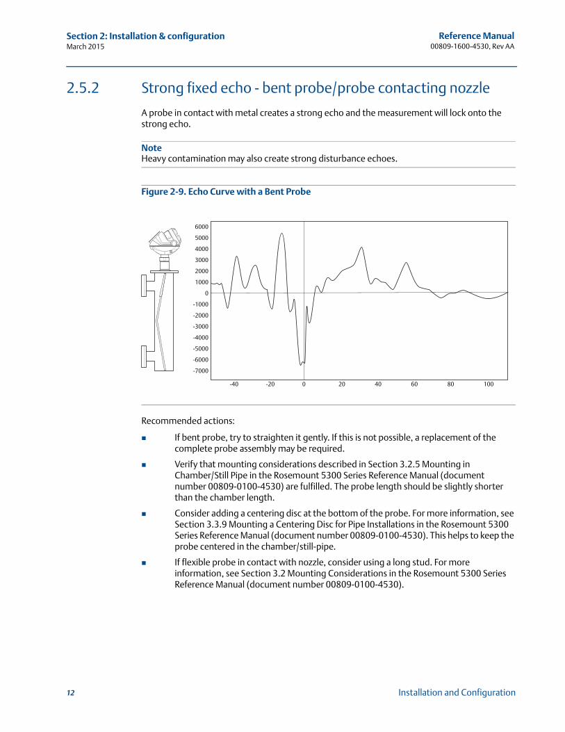
NoteFigure 2-8 illustrates the key elements of a theoretical echo curve. In an actual echo curve, the probe end pulse and the probe end echo threshold line are not visible in an interface application, they are shown for illustration purposes only.
10 Installation and Configuration
Reference Manual 00809-1600-4530, Rev AA
Section 2: Installation & configurationMarch 2015
Figure 2-8. The Echo Curve Presents All Visible Echoes
2.5 Common problems and recommended actions
2.5.1 Double bounce
Tall, narrow, and/or rough nozzles may create double bounces, which disturb the measurement signal. The double bounce always appears at twice the disturbance distance. For example, the end of the nozzle may create a peak at 10 in. (254 mm). A second peak will appear at 20 in. (500 mm).
NoteTrim Near Zone should not be completed when the unit is installed in an empty metal tank. A small amount of fluid should be added before the Trim Near Zone step is completed.
Recommended actions:
Verify that mounting considerations are followed, as described in Section 3.2 Mounting Considerations in the Rosemount 5300 Series Reference Manual (document number 00809-0100-4530).
Perform Trim Near Zone. See Appendix C.3.1 Use the Trim Near Zone Function in the Rosemount 5300 Series Reference Manual (document number 00809-0100-4530) for activation details. Fine-tune performance by trimming echoes in the near zone.
Adjust Upper Null Zone (UNZ). See Appendix C.3.2 Changing the Hold Off Distance/Upper Null Zone in the Rosemount 5300 Series Reference Manual (document number 00809-0100-4530) for details. Exclude any echo “before” the UNZ.
Adjust Surface Threshold (ATC). See Appendix C.4 Threshold Settings in the Rosemount 5300 Series Reference Manual (document number 00809-0100-4530) for details. Exclude any echo weaker than the threshold.
AB
C
D
2000
1500
1000
0
-1000
-1500
- 1.0 0 1.0 2.0 3.0 4.0 5.0 6.0
Am
plit
ude,
mV
Distance, m
A. Interface thresholdB. Surface threshold (ATC)C. Probe end thresholdD. Reference threshold
11Installation and Configuration
Reference Manual 00809-1600-4530, Rev AA
Section 2: Installation & configurationMarch 2015
2.5.2 Strong fixed echo - bent probe/probe contacting nozzle
A probe in contact with metal creates a strong echo and the measurement will lock onto the strong echo.
Note Heavy contamination may also create strong disturbance echoes.
Figure 2-9. Echo Curve with a Bent Probe
Recommended actions:
If bent probe, try to straighten it gently. If this is not possible, a replacement of the complete probe assembly may be required.
Verify that mounting considerations described in Section 3.2.5 Mounting in Chamber/Still Pipe in the Rosemount 5300 Series Reference Manual (document number 00809-0100-4530) are fulfilled. The probe length should be slightly shorter than the chamber length.
Consider adding a centering disc at the bottom of the probe. For more information, see Section 3.3.9 Mounting a Centering Disc for Pipe Installations in the Rosemount 5300 Series Reference Manual (document number 00809-0100-4530). This helps to keep the probe centered in the chamber/still-pipe.
If flexible probe in contact with nozzle, consider using a long stud. For more information, see Section 3.2 Mounting Considerations in the Rosemount 5300 Series Reference Manual (document number 00809-0100-4530).
6000
5000
4000
3000
2000
1000
0
-1000
-2000
-3000
-4000
-5000
-6000
-7000
-40 -20 0 20 40 60 80 100
12 Installation and Configuration
Reference Manual 00809-1600-4530, Rev AA
Section 2: Installation & configurationMarch 2015
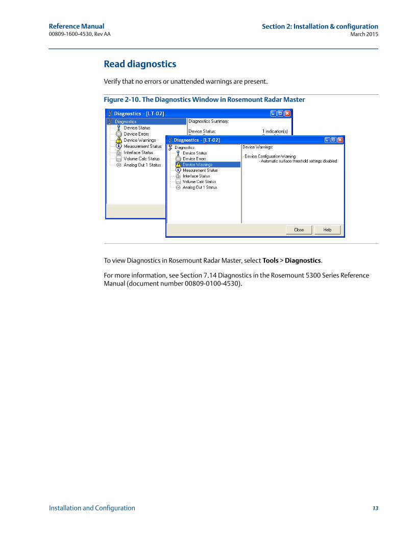
Read diagnostics
Verify that no errors or unattended warnings are present.
Figure 2-10. The Diagnostics Window in Rosemount Radar Master
To view Diagnostics in Rosemount Radar Master, select Tools > Diagnostics.
For more information, see Section 7.14 Diagnostics in the Rosemount 5300 Series Reference Manual (document number 00809-0100-4530).
13Installation and Configuration
Reference Manual 00809-1600-4530, Rev AA
Section 2: Installation & configurationMarch 2015
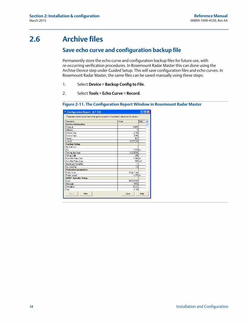
2.6 Archive filesSave echo curve and configuration backup file
Permanently store the echo curve and configuration backup files for future use, with re-occurring verification procedures. In Rosemount Radar Master this can done using the Archive Device step under Guided Setup. This will save configuration files and echo curves. In Rosemount Radar Master, the same files can be saved manually using these steps:
1. Select Device > Backup Config to File.
2. Select Tools > Echo Curve > Record.
Figure 2-11. The Configuration Report Window in Rosemount Radar Master
14 Installation and Configuration
Reference Manual 00809-1600-4530, Rev AA
Section 3: Verification and Validation of GWR without Fluid
Section 3 Verification and Validation of GWR without Fluid
Verification . . . . . . . . . . . . . . . . . . . . . . . . . . . . . . . . . . . . . . . . . . . . . . . . . . . . . . . . . . . . . . . . . 15Validation of device . . . . . . . . . . . . . . . . . . . . . . . . . . . . . . . . . . . . . . . . . . . . . . . . . . . . . . . . . 20
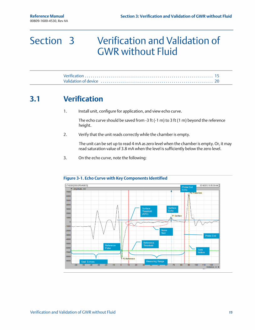
3.1 Verification
1. Install unit, configure for application, and view echo curve.
The echo curve should be saved from -3 ft (-1 m) to 3 ft (1 m) beyond the reference height.
2. Verify that the unit reads correctly while the chamber is empty.
The unit can be set up to read 4 mA as zero level when the chamber is empty. Or, it may read saturation value of 3.8 mA when the level is sufficiently below the zero level.
3. On the echo curve, note the following:
Figure 3-1. Echo Curve with Key Components Identified
15Verification and Validation of GWR without Fluid
Reference Manual 00809-1600-4530, Rev AA
Section 3: Verification and Validation of GWR without FluidMarch 2015
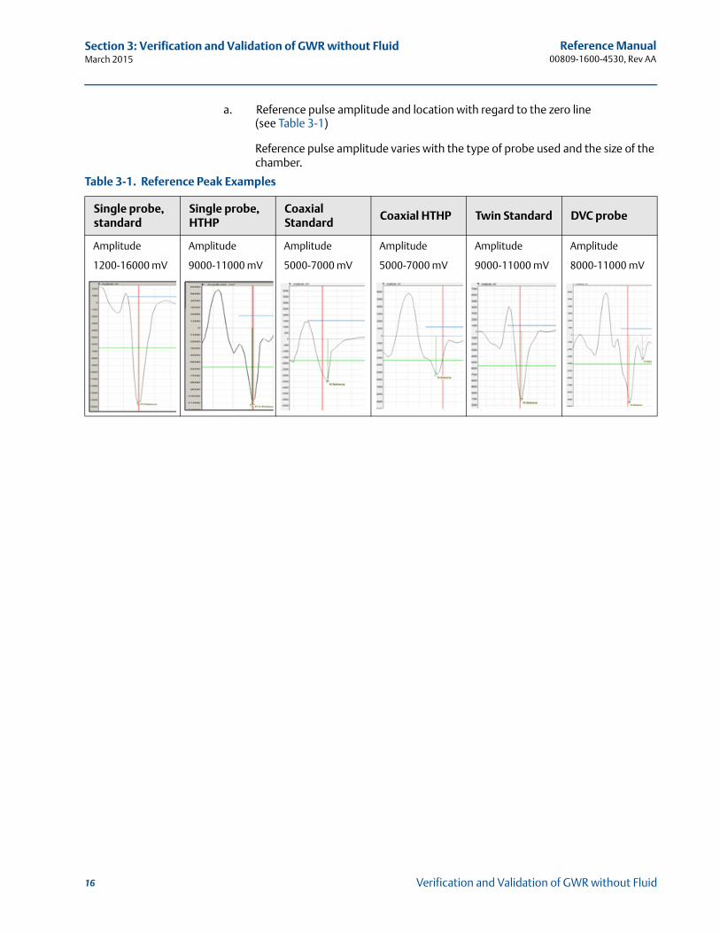
a. Reference pulse amplitude and location with regard to the zero line (see Table 3-1)
Reference pulse amplitude varies with the type of probe used and the size of the chamber.
Table 3-1. Reference Peak Examples
Single probe, standard
Single probe, HTHP
Coaxial Standard
Coaxial HTHP Twin Standard DVC probe
Amplitude
1200-16000 mV
Amplitude
9000-11000 mV
Amplitude
5000-7000 mV
Amplitude
5000-7000 mV
Amplitude
9000-11000 mV
Amplitude
8000-11000 mV
16 Verification and Validation of GWR without Fluid
Reference Manual 00809-1600-4530, Rev AA
Section 3: Verification and Validation of GWR without Fluid
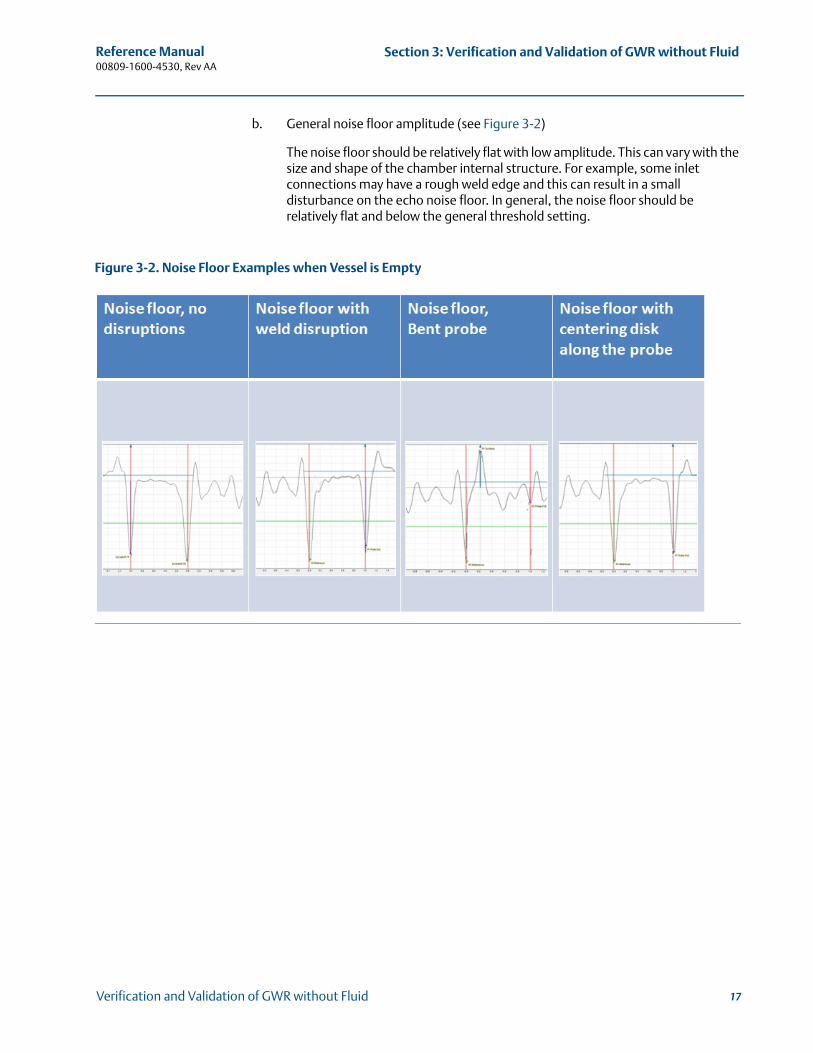
b. General noise floor amplitude (see Figure 3-2)
The noise floor should be relatively flat with low amplitude. This can vary with the size and shape of the chamber internal structure. For example, some inlet connections may have a rough weld edge and this can result in a small disturbance on the echo noise floor. In general, the noise floor should be relatively flat and below the general threshold setting.
Figure 3-2. Noise Floor Examples when Vessel is Empty
17Verification and Validation of GWR without Fluid
Reference Manual 00809-1600-4530, Rev AA
Section 3: Verification and Validation of GWR without FluidMarch 2015
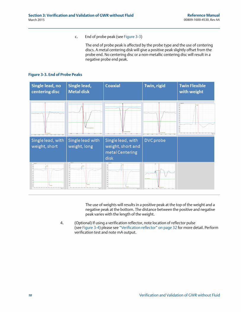
c. End of probe peak (see Figure 3-3)
The end of probe peak is affected by the probe type and the use of centering discs. A metal centering disk will give a positive peak slightly offset from the probe end. No centering disc or a non-metallic centering disc will result in a negative probe end peak.
Figure 3-3. End of Probe Peaks
The use of weights will results in a positive peak at the top of the weight and a negative peak at the bottom. The distance between the positive and negative peak varies with the length of the weight.
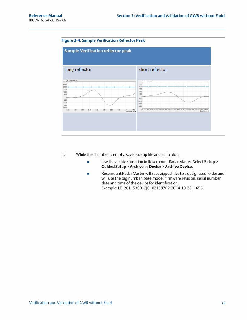
4. (Optional) If using a verification reflector, note location of reflector pulse (see Figure 3-4) please see “Verification reflector” on page 32 for more detail. Perform verification test and note mA output.
18 Verification and Validation of GWR without Fluid
Reference Manual 00809-1600-4530, Rev AA
Section 3: Verification and Validation of GWR without Fluid
Figure 3-4. Sample Verification Reflector Peak
5. While the chamber is empty, save backup file and echo plot.
Use the archive function in Rosemount Radar Master. Select Setup > Guided Setup > Archive or Device > Archive Device.
Rosemount Radar Master will save zipped files to a designated folder and will use the tag number, base model, firmware revision, serial number, date and time of the device for identification. Example: LT_201_5300_2J0_#2158762-2014-10-28_1656.
19Verification and Validation of GWR without Fluid
Reference Manual 00809-1600-4530, Rev AA
Section 3: Verification and Validation of GWR without FluidMarch 2015
3.2 Validation of device
To validate the functionality of a device after it has been in service, it is possible to compare the current readings to baseline readings. To obtain the current readings, follow the same steps that were outlined under verification. A new set of files showing the configuration data and the echo curves should be obtained and compared to the initial set.
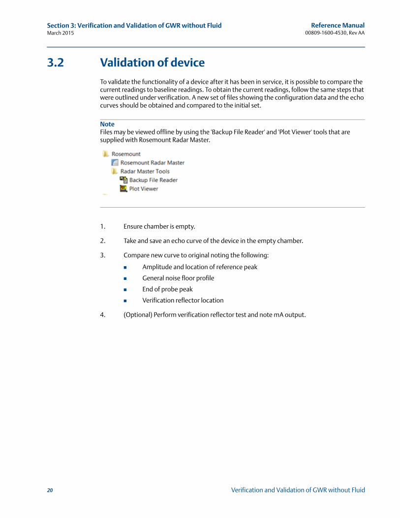
NoteFiles may be viewed offline by using the 'Backup File Reader' and 'Plot Viewer' tools that are supplied with Rosemount Radar Master.
1. Ensure chamber is empty.
2. Take and save an echo curve of the device in the empty chamber.
3. Compare new curve to original noting the following:
Amplitude and location of reference peak
General noise floor profile
End of probe peak
Verification reflector location
4. (Optional) Perform verification reflector test and note mA output.
20 Verification and Validation of GWR without Fluid
Reference Manual 00809-1600-4530, Rev AA
Section 3: Verification and Validation of GWR without Fluid
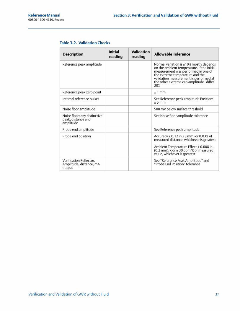
Table 3-2. Validation Checks
DescriptionInitial reading
Validation reading
Allowable Tolerance
Reference peak amplitude Normal variation is ±10% mostly depends on the ambient temperature. If the initial measurement was performed in one of the extreme temperature and the validation measurement is performed at the other extreme can amplitude differ 20%
Reference peak zero point ± 1 mm
Internal reference pulses See Reference peak amplitude Position: ± 5 mm
Noise floor amplitude 500 mV below surface threshold
Noise floor: any distinctive peak, distance and amplitude
See Noise floor amplitude tolerance
Probe end amplitude See Reference peak amplitude
Probe end position Accuracy ± 0.12 in. (3 mm) or 0.03% of measured distance, whichever is greatest
Ambient Temperature Effect ± 0.008 in. (0.2 mm)/K or ± 30 ppm/K of measured value, whichever is greatest
Verification Reflector, Amplitude, distance, mA output
See “Reference Peak Amplitude” and “Probe End Position” tolerance
21Verification and Validation of GWR without Fluid
Reference Manual 00809-1600-4530, Rev AA
Section 3: Verification and Validation of GWR without FluidMarch 2015
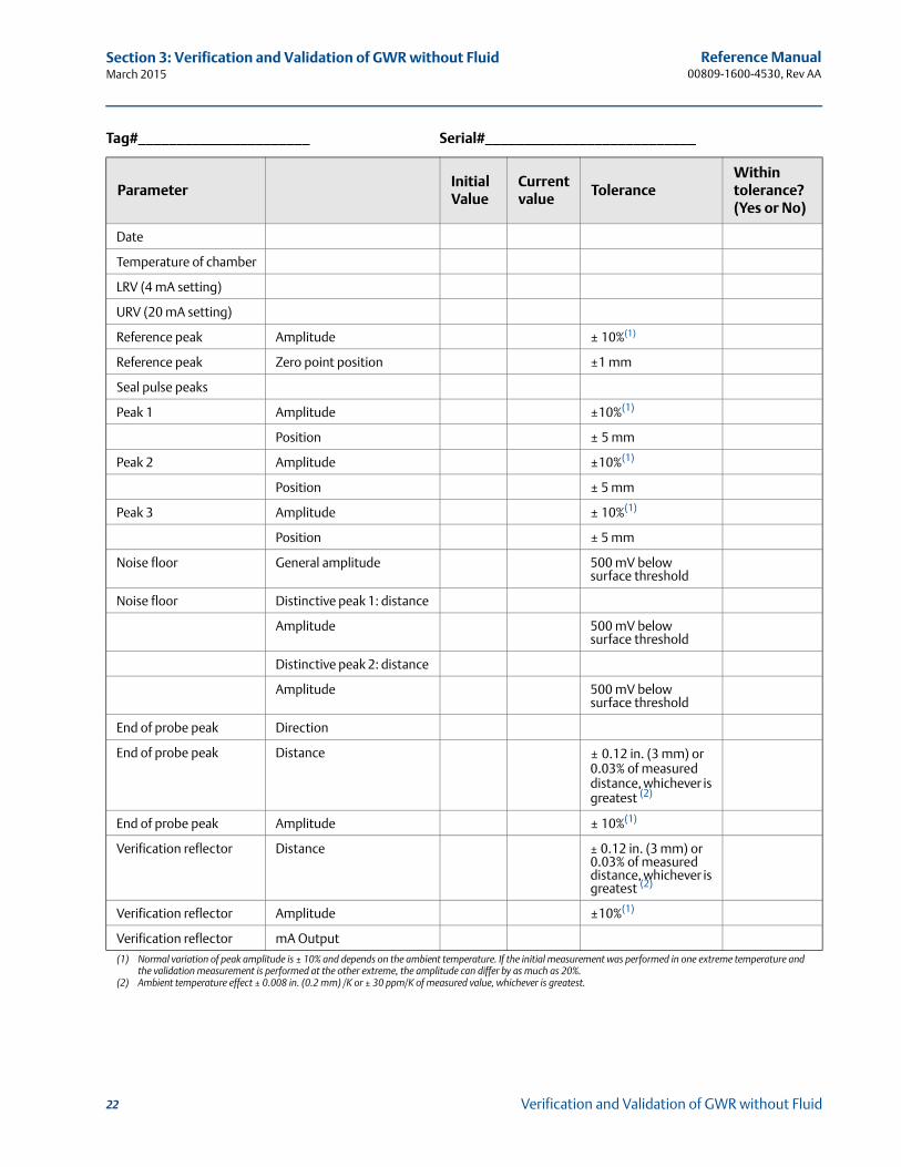
Tag#______________________ Serial#___________________________
ParameterInitial Value
Current value
ToleranceWithin tolerance? (Yes or No)
Date
Temperature of chamber
LRV (4 mA setting)
URV (20 mA setting)
Reference peak Amplitude ± 10%(1)
(1) Normal variation of peak amplitude is ± 10% and depends on the ambient temperature. If the initial measurement was performed in one extreme temperature and the validation measurement is performed at the other extreme, the amplitude can differ by as much as 20%.
Reference peak Zero point position ±1 mm
Seal pulse peaks
Peak 1 Amplitude ±10%(1)
Position ± 5 mm
Peak 2 Amplitude ±10%(1)
Position ± 5 mm
Peak 3 Amplitude ± 10%(1)
Position ± 5 mm
Noise floor General amplitude 500 mV below surface threshold
Noise floor Distinctive peak 1: distance
Amplitude 500 mV below surface threshold
Distinctive peak 2: distance
Amplitude 500 mV below surface threshold
End of probe peak Direction
End of probe peak Distance ± 0.12 in. (3 mm) or 0.03% of measured distance, whichever is greatest (2)
(2) Ambient temperature effect ± 0.008 in. (0.2 mm) /K or ± 30 ppm/K of measured value, whichever is greatest.
End of probe peak Amplitude ± 10%(1)
Verification reflector Distance ± 0.12 in. (3 mm) or 0.03% of measured distance, whichever is greatest (2)
Verification reflector Amplitude ±10%(1)
Verification reflector mA Output
22 Verification and Validation of GWR without Fluid
Reference Manual 00809-1600-4530, Rev AA
Section 4: Verification Procedure with FluidMarch 2015
Section 4 Verification Procedure with Fluid
Verification procedure with active level measurement . . . . . . . . . . . . . . . . . . . . . . . . . . . page 23Common problems and recommended actions . . . . . . . . . . . . . . . . . . . . . . . . . . . . . . . . . page 25Transmitter diagnostics review . . . . . . . . . . . . . . . . . . . . . . . . . . . . . . . . . . . . . . . . . . . . . . . page 27Monitor level while emptying . . . . . . . . . . . . . . . . . . . . . . . . . . . . . . . . . . . . . . . . . . . . . . . . . page 27Echo curve verification with empty tank . . . . . . . . . . . . . . . . . . . . . . . . . . . . . . . . . . . . . . . page 29Monitor level while filling . . . . . . . . . . . . . . . . . . . . . . . . . . . . . . . . . . . . . . . . . . . . . . . . . . . . page 29Archive files . . . . . . . . . . . . . . . . . . . . . . . . . . . . . . . . . . . . . . . . . . . . . . . . . . . . . . . . . . . . . . . . page 29
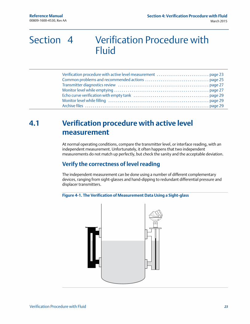
4.1 Verification procedure with active level measurement
At normal operating conditions, compare the transmitter level, or interface reading, with an independent measurement. Unfortunately, it often happens that two independent measurements do not match up perfectly, but check the sanity and the acceptable deviation.
Verify the correctness of level reading
The independent measurement can be done using a number of different complementary devices, ranging from sight-glasses and hand-dipping to redundant differential pressure and displacer transmitters.
Figure 4-1. The Verification of Measurement Data Using a Sight-glass
23Verification Procedure with Fluid
Reference Manual 00809-1600-4530, Rev AA
Section 4: Verification Procedure with FluidMarch 2015
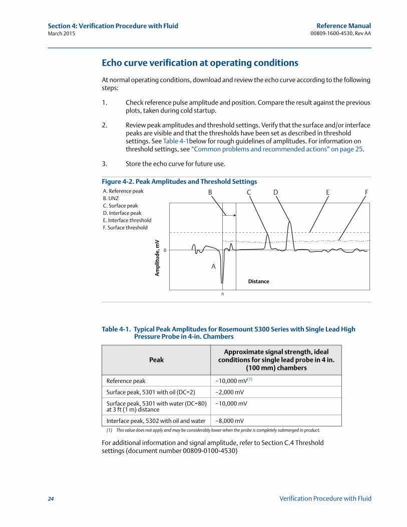
Echo curve verification at operating conditions
At normal operating conditions, download and review the echo curve according to the following steps:
1. Check reference pulse amplitude and position. Compare the result against the previous plots, taken during cold startup.
2. Review peak amplitudes and threshold settings. Verify that the surface and/or interface peaks are visible and that the thresholds have been set as described in threshold settings. See Table 4-1below for rough guidelines of amplitudes. For information on threshold settings, see “Common problems and recommended actions” on page 25.
3. Store the echo curve for future use.
Figure 4-2. Peak Amplitudes and Threshold Settings
Table 4-1. Typical Peak Amplitudes for Rosemount 5300 Series with Single Lead High Pressure Probe in 4-in. Chambers
PeakApproximate signal strength, ideal
conditions for single lead probe in 4 in.(100 mm) chambers
Reference peak ~10,000 mV(1)
(1) This value does not apply and may be considerably lower when the probe is completely submerged in product.
For additional information and signal amplitude, refer to Section C.4 Threshold settings (document number 00809-0100-4530)
Surface peak, 5301 with oil (DC=2) ~2,000 mV
Surface peak, 5301 with water (DC=80)at 3 ft (1 m) distance
~10,000 mV
Interface peak, 5302 with oil and water ~8,000 mV
A
B C D E FA. Reference peakB. UNZC. Surface peakD. Interface peakE. Interface thresholdF. Surface threshold
Distance
Am
plit
ud
e, m
V
24 Verification Procedure with Fluid
Reference Manual 00809-1600-4530, Rev AA
Section 4: Verification Procedure with FluidMarch 2015
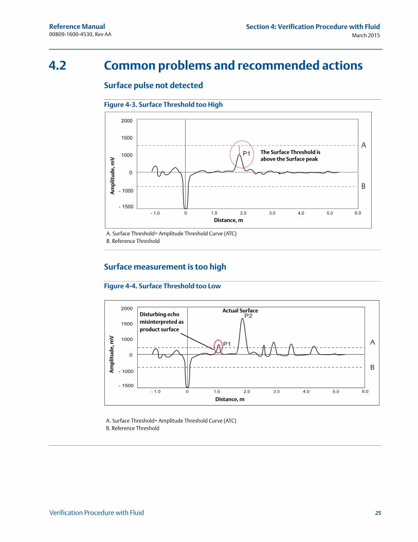
4.2 Common problems and recommended actions
Surface pulse not detected
Figure 4-3. Surface Threshold too High
Surface measurement is too high
Figure 4-4. Surface Threshold too Low
3.0 5.0
A
B
The Surface Threshold is above the Surface peak
Distance, m
Am
plit
ud
e, m
V
A. Surface Threshold= Amplitude Threshold Curve (ATC)B. Reference Threshold
3.0 5.0
A
B
Am
plit
ud
e, m
V
Distance, m
A. Surface Threshold= Amplitude Threshold Curve (ATC)B. Reference Threshold
Disturbing echomisinterpreted asproduct surface
Actual Surface
25Verification Procedure with Fluid
Reference Manual 00809-1600-4530, Rev AA
Section 4: Verification Procedure with FluidMarch 2015
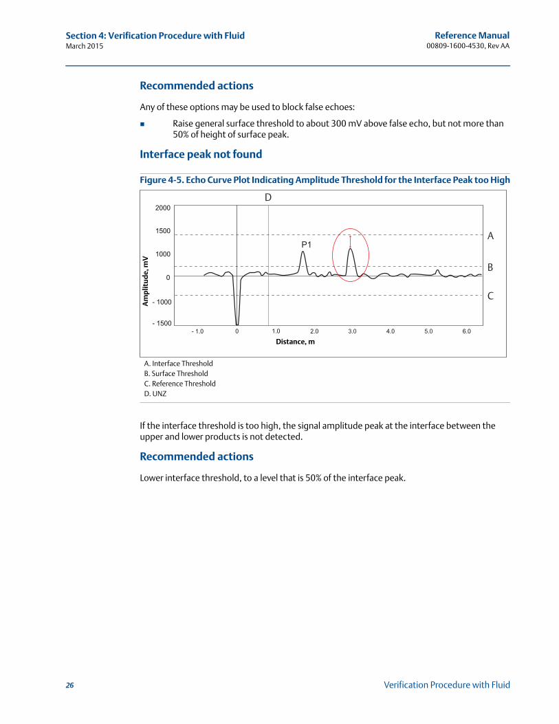
Recommended actions
Any of these options may be used to block false echoes:
Raise general surface threshold to about 300 mV above false echo, but not more than 50% of height of surface peak.
Interface peak not found
Figure 4-5. Echo Curve Plot Indicating Amplitude Threshold for the Interface Peak too High
If the interface threshold is too high, the signal amplitude peak at the interface between the upper and lower products is not detected.
Recommended actions
Lower interface threshold, to a level that is 50% of the interface peak.
A
B
C
3.0 5.0
D
Am
plit
ud
e, m
V
Distance, m
A. Interface ThresholdB. Surface ThresholdC. Reference ThresholdD. UNZ
26 Verification Procedure with Fluid
Reference Manual 00809-1600-4530, Rev AA
Section 4: Verification Procedure with FluidMarch 2015
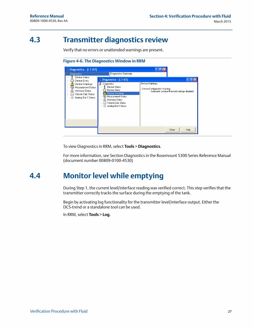
4.3 Transmitter diagnostics reviewVerify that no errors or unattended warnings are present.
Figure 4-6. The Diagnostics Window in RRM
To view Diagnostics in RRM, select Tools > Diagnostics.
For more information, see Section Diagnostics in the Rosemount 5300 Series Reference Manual (document number 00809-0100-4530)
4.4 Monitor level while emptying
During Step 1, the current level/interface reading was verified correct. This step verifies that the transmitter correctly tracks the surface during the emptying of the tank.
Begin by activating log functionality for the transmitter level/interface output. Either the DCS-trend or a standalone tool can be used.
In RRM, select Tools > Log.
27Verification Procedure with Fluid
Reference Manual 00809-1600-4530, Rev AA
Section 4: Verification Procedure with FluidMarch 2015
Figure 4-7. Log Registers
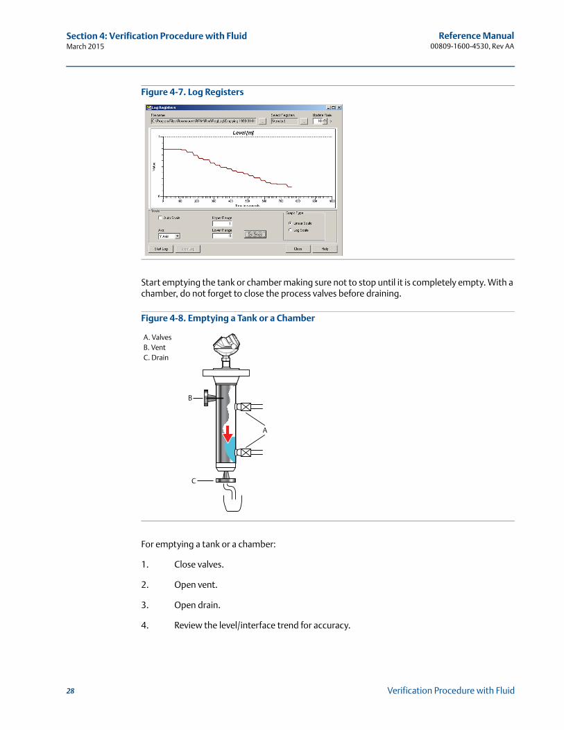
Start emptying the tank or chamber making sure not to stop until it is completely empty. With a chamber, do not forget to close the process valves before draining.
Figure 4-8. Emptying a Tank or a Chamber
For emptying a tank or a chamber:
1. Close valves.
2. Open vent.
3. Open drain.
4. Review the level/interface trend for accuracy.
B
C
A
A. ValvesB. VentC. Drain
28 Verification Procedure with Fluid
Reference Manual 00809-1600-4530, Rev AA
Section 4: Verification Procedure with FluidMarch 2015
4.5 Echo curve verification with empty tank
When the tank or chamber is empty, download and review the echo curve according to the following steps:
1. Compare the echo curve with previous plots, taken during commissioning. There should be no major differences. Especially make sure to review:
The amplitude and position of the reference pulse
If all noise is below the threshold
The amplitude and position of the bottom or probe-end pulse
2. Store the echo curve for future use.
4.6 Monitor level while filling
Repeat “Monitor level while emptying” on page 27, but fill the tank or chamber instead of emptying it.
4.7 Archive files
Save echo curve and configuration backup file
Permanently store the echo curve and configuration backup files for future use, with re-occurring verification procedures.
For storing the echo curve in RRM, select Tools > Echo Curve > Record.
For saving a configuration backup file in RRM, select Device > Backup Config to File.
29Verification Procedure with Fluid
Reference Manual 00809-1600-4530, Rev AA
Section 4: Verification Procedure with FluidMarch 2015
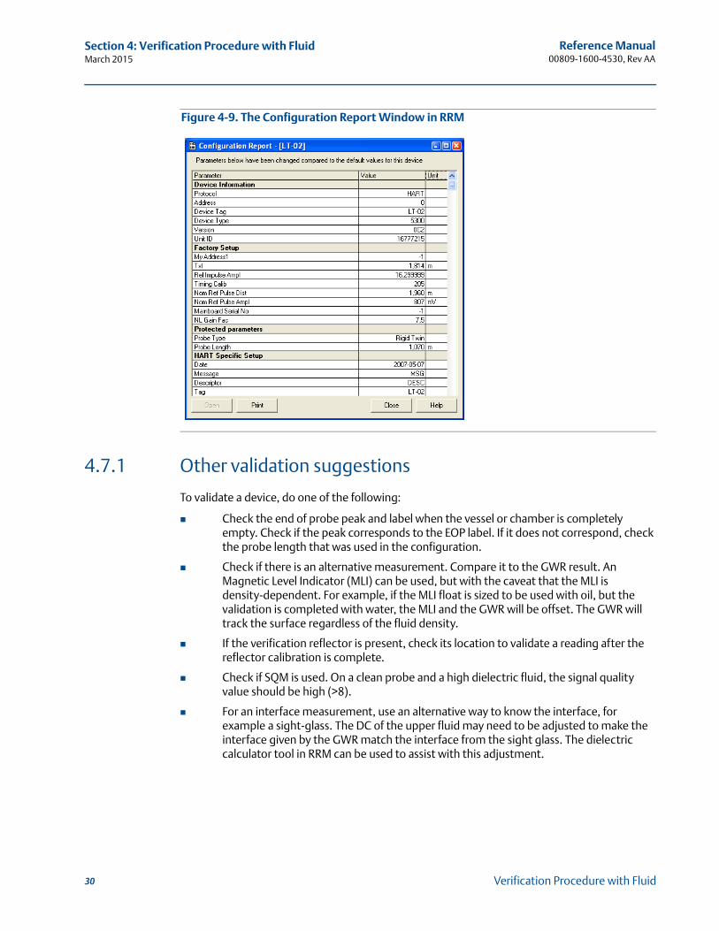
Figure 4-9. The Configuration Report Window in RRM
4.7.1 Other validation suggestions
To validate a device, do one of the following:
Check the end of probe peak and label when the vessel or chamber is completely empty. Check if the peak corresponds to the EOP label. If it does not correspond, check the probe length that was used in the configuration.
Check if there is an alternative measurement. Compare it to the GWR result. An Magnetic Level Indicator (MLI) can be used, but with the caveat that the MLI is density-dependent. For example, if the MLI float is sized to be used with oil, but the validation is completed with water, the MLI and the GWR will be offset. The GWR will track the surface regardless of the fluid density.
If the verification reflector is present, check its location to validate a reading after the reflector calibration is complete.
Check if SQM is used. On a clean probe and a high dielectric fluid, the signal quality value should be high (>8).
For an interface measurement, use an alternative way to know the interface, for example a sight-glass. The DC of the upper fluid may need to be adjusted to make the interface given by the GWR match the interface from the sight glass. The dielectric calculator tool in RRM can be used to assist with this adjustment.
30 Verification Procedure with Fluid
Reference Manual 00809-1600-4530, Rev AA
Section 5: Additional OptionsMarch 2015
Section 5 Additional Options
Introduction . . . . . . . . . . . . . . . . . . . . . . . . . . . . . . . . . . . . . . . . . . . . . . . . . . . . . . . . . . . . . . . page 31Signal Quality Metrics (SQM) . . . . . . . . . . . . . . . . . . . . . . . . . . . . . . . . . . . . . . . . . . . . . . . . . page 31Verification reflector . . . . . . . . . . . . . . . . . . . . . . . . . . . . . . . . . . . . . . . . . . . . . . . . . . . . . . . . page 32
5.1 Introduction
Additional options are available for the Rosemount 5300 that can be useful for diagnostics under operating conditions.
5.2 Signal Quality Metrics (SQM)
SQM indicates the surface signal integrity compared to the noise. It can be used to schedule maintenance to clean the probe or detect and monitor turbulence, boiling, foam, and emulsions.
The following diagnostics measurements are available:
Signal quality is a measurement of the surface peak amplitude compared to the surface threshold (ATC) and the smallest marginal between the noise and the ATC above the surface (indicated with a circle) compared to the ATC. The signal quality spans from 0 to 10, where 0 indicates a low margin, and 10 indicates a high margin. It indicates how much margin there is until the noise peak is indicated as the surface level. Surface/noise margin is the relationship between surface peak amplitude and the amplitude of the strongest noise peak above the surface. The surface/noise margin spans from 0 to 10, where 0 indicates a low margin, and 10 indicates a high margin. It indicates how much disturbance the device can handle in the tank.
NoteSince signal quality is reflective of the surface conditions, the probe, and the threshold settings, it intended to be used while the device is measuring level. It is not considered a valid parameter when the tank or chamber is empty.
NoteThe signal amplitude and the noise margin depend on probe type and application conditions, as well as the condition of the probe. Even if the probe is clean, signal quality and surface/noise margin may not be a 10.
To check if the SQM function is supported, do one of the following:
If “DA1” or “D01” is mentioned in the model code on the label, the device supports Signal Quality Metrics. Model Code: 530xxxxxxxxxxxxxxxxDA1 or 530xxxxxxxxxxxxxxxxD01xx
31Additional Options
Reference Manual 00809-1600-4530, Rev AA
Section 5: Additional OptionsMarch 2015
In Rosemount Radar Master:
1. Connect to the device.
2. Right click on the device and select Properties.
3. If “Diagnostics Suite” is mentioned in the Device Software Configuration 2 list, the device supports Signal Quality Metrics.
In a Field Communicator, if SQM is supported, it can be found with the [3, 2, 2, 1] sequence. Check if “Diagnostics Suite” is present.
SQM can be enabled/disabled in Rosemount Radar Master. Select Setup > Advanced and select the Signal Quality Metrics tab.
NoteIf SQM is not supported or disabled, the signal quality and surface/noise margin will always be set to 0.
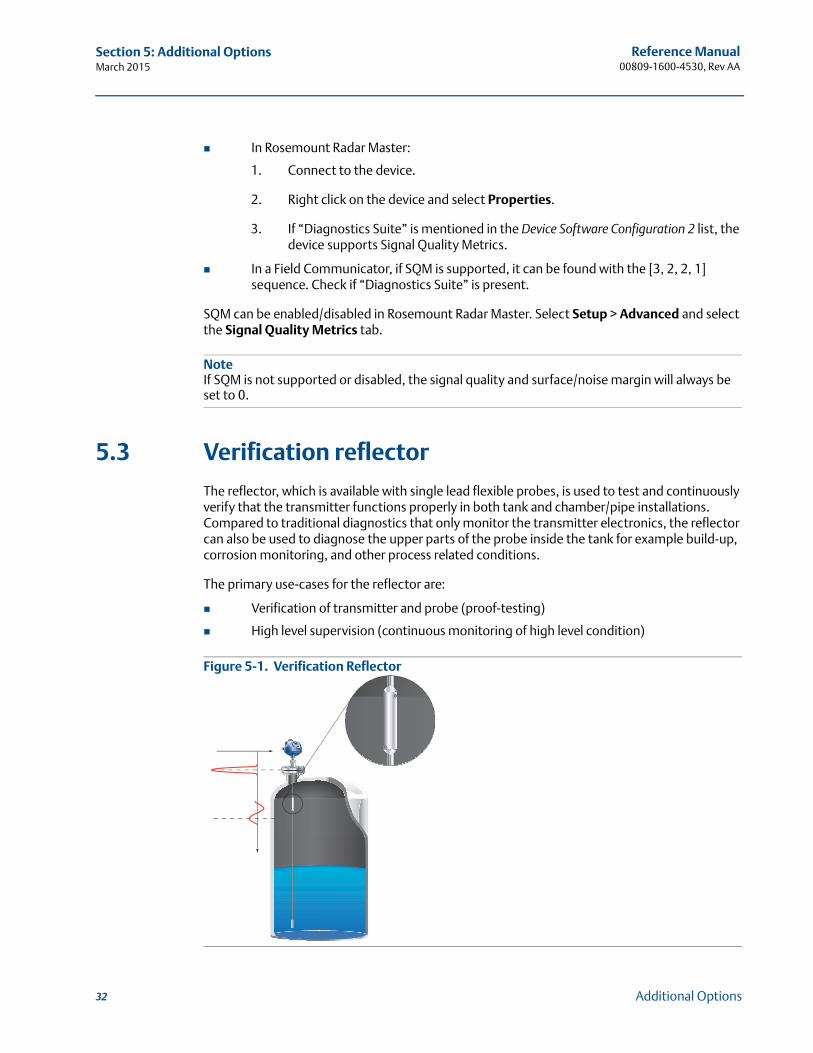
5.3 Verification reflector
The reflector, which is available with single lead flexible probes, is used to test and continuously verify that the transmitter functions properly in both tank and chamber/pipe installations. Compared to traditional diagnostics that only monitor the transmitter electronics, the reflector can also be used to diagnose the upper parts of the probe inside the tank for example build-up, corrosion monitoring, and other process related conditions.
The primary use-cases for the reflector are:
Verification of transmitter and probe (proof-testing)
High level supervision (continuous monitoring of high level condition)
Figure 5-1. Verification Reflector
32 Additional Options
Reference Manual 00809-1600-4530, Rev AA
Section 5: Additional OptionsMarch 2015
5.3.1 High level supervision
Additionally, the reflector’s unique echo characteristics aid the transmitter to locate a liquid surface above the reflector, thereby offering increased reliability to detect high level conditions at a user selectable limit. The transmitter continuously monitors the status of the reflector and abnormal conditions generate alarms and alerts as appropriate.
5.3.2 Limitations for verification reflector Not to be used in fully submerged applications
Minimum dielectric constant:
2.4 (for option code HL1)2.0 (for option code HL2 and HL3)
Verification reflector must be installed at least 20 in. (0.5 m) below the flange face. In addition, during the calibration procedure, the level surface must be as least 20 in. (0.5 m) below the reflector.
More information
For more information and installation requirements, refer to the High Level Supervision Manual (document number 00809-0900-4530).
33Additional Options

34
Reference Manual 00809-1600-4530, Rev AA
Section 5: Additional OptionsMarch 2015
Additional Options
Reference Manual 00809-1600-4530, Rev AA
Section 6: SIS InstallationsMarch 2015
Section 6 SIS Installations
Installation in SIS applications . . . . . . . . . . . . . . . . . . . . . . . . . . . . . . . . . . . . . . . . . . . . . . . . page 35Configuring in SIS applications . . . . . . . . . . . . . . . . . . . . . . . . . . . . . . . . . . . . . . . . . . . . . . . . page 36SIS operation and maintenance . . . . . . . . . . . . . . . . . . . . . . . . . . . . . . . . . . . . . . . . . . . . . . . page 37
6.1 Installation in SIS applications
The device should be installed and configured as a level sensing device per manufacturer’s instructions. The materials must be compatible with process conditions and process fluids. No special installation is required in addition to the standard installation practices outlined in this manual.
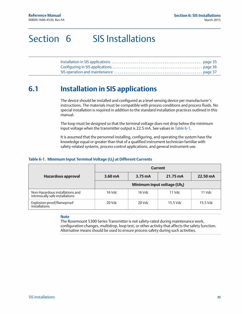
The loop must be designed so that the terminal voltage does not drop below the minimum input voltage when the transmitter output is 22.5 mA. See values in Table 6-1.
It is assumed that the personnel installing, configuring, and operating the system have the knowledge equal or greater than that of a qualified instrument technician familiar with safety-related systems, process control applications, and general instrument use.
Table 6-1. Minimum Input Terminal Voltage (Ui) at Different Currents
NoteThe Rosemount 5300 Series Transmitter is not safety-rated during maintenance work, configuration changes, multidrop, loop test, or other activity that affects the safety function. Alternative means should be used to ensure process safety during such activities.
Hazardous approval
Current
3.60 mA 3.75 mA 21.75 mA 22.50 mA
Minimum input voltage (Uhi)
Non-Hazardous installations andintrinsically safe installations
16 Vdc 16 Vdc 11 Vdc 11 Vdc
Explosion-proof/flameproofinstallations
20 Vdc 20 Vdc 15.5 Vdc 15.5 Vdc
35SIS Installations
Reference Manual 00809-1600-4530, Rev AA
Section 6: SIS InstallationsMarch 2015
6.2 Configuring in SIS applications
Use a HART® compliant master, such as Rosemount Radar Master (RRM) or a Field Communicator, to communicate with and verify configuration of the Rosemount 5300 Series. These instructions are applicable to the Rosemount 5300 Series safety-certified options with any differences noted.
Damping
User-adjusted damping will affect the transmitter’s ability to respond to process changes. Therefore, the damping values + response time should not exceed the loop requirements.
Alarm and saturation levels
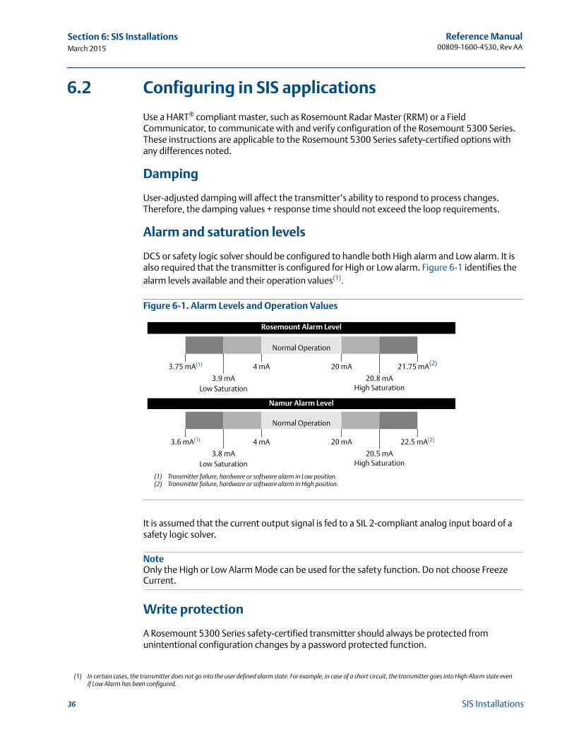
DCS or safety logic solver should be configured to handle both High alarm and Low alarm. It is also required that the transmitter is configured for High or Low alarm. Figure 6-1 identifies the alarm levels available and their operation values(1).
Figure 6-1. Alarm Levels and Operation Values
It is assumed that the current output signal is fed to a SIL 2-compliant analog input board of a safety logic solver.
NoteOnly the High or Low Alarm Mode can be used for the safety function. Do not choose Freeze Current.
Write protection
A Rosemount 5300 Series safety-certified transmitter should always be protected from unintentional configuration changes by a password protected function.
(1) In certain cases, the transmitter does not go into the user defined alarm state. For example, in case of a short circuit, the transmitter goes into High Alarm state even if Low Alarm has been configured.
Rosemount Alarm Level
Normal Operation
3.75 mA(1)
(1) Transmitter failure, hardware or software alarm in Low position.
4 mA 20 mA 21.75 mA(2)
3.9 mA Low Saturation
20.8 mA High Saturation
Namur Alarm Level
Normal Operation
3.6 mA(1) 4 mA 20 mA 22.5 mA(2)
(2) Transmitter failure, hardware or software alarm in High position.
3.8 mALow Saturation
20.5 mAHigh Saturation
36 SIS Installations
Reference Manual 00809-1600-4530, Rev AA
Section 6: SIS InstallationsMarch 2015
Site acceptance
After installation and/or configuration, proper operation of the transmitter (including verification of all configuration changes) must be verified. A site acceptance test is therefore required. The proof test outlined in this document can be used for this.
6.3 SIS operation and maintenance
6.3.1 Proof test
The following proof test is recommended. If an error is found in the safety function, the measuring system must be switched out of service and the process held in a safe state by means of other measures. Proof test results and corrective actions taken must be documented at http://www.rosemount.com/safety.
NoteFor a valid result, always perform the proof test on the product that will be stored in the tank while the device is in operation.
NoteBefore every test, make sure you are connected to the correct transmitter by verifying QT/QS in the model code on the label and your software version. Also verify that the serial number on the label matches the one in your configuration tool. Make sure to enable write protection as soon as you are finished.
Required tools: HART host/communicator and mA meter.
Note that prior to these tests, inspect the echo curve to ensure that no disturbing echoes affecting the measurement performance are present.
RRM: AMS Device Manager and Field Communicator:
Go to Setup > Echo Curve. Go to Service Tools > Echo tuning > Echo Curve.
37SIS Installations
Reference Manual 00809-1600-4530, Rev AA
Section 6: SIS InstallationsMarch 2015
Suggested comprehensive proof test
The suggested proof test described below detects approximately 89% in of possible Dangerous Undetected (DU) failures in the Rosemount 5300 Series Transmitters.
1. Bypass the safety function and take appropriate action to avoid a false trip.
2. Disable write protection in device (if enabled).
3. Retrieve any diagnostics and take appropriate action.
4. Using Loop Test, enter current value (mA) representing high alarm current. Verify that analog output current and terminal voltage are correct using reference meters.This step tests for voltage compliance problems, such as low power supply voltage or increased wiring resistance.
RRM: AMS Device Manager and Field Communicator:
a. In the Tools menu, select Lock/Unlock Configuration Area.
b. Enter Password to unlock.
a. Go to Configure > Manual Setup > Device Setup > Security.
For HART Device Revision 3: go to Device Diagnostics > Tools > General.
b. Select Write Protect and follow the instructions.
RRM: AMS Device Manager and Field Communicator:
Go to Tools > Diagnostics. See the Rosemount 5300 Series Reference Manual (document number 00809-0100-4530, diagnostic messages) for recommended actions.
Go to Service Tools > Alerts. See the Rosemount 5300 Series Reference Manual (document number 00809-0100-4530, diagnostic messages) for recommended actions.
For HART Device Revision 3: go to Device Diagnostics > Diagnostics.
RRM: AMS Device Manager and Field Communicator:
a. Go to Setup > Output > Analog Out 1 and select Loop test.
b. Enter current value representing high alarm current.
c. Select Start to output current.
d. Verify that analog output current is correct.
e. Verify that terminal voltage is correct. See values in Table 6-1.
f. Select Stop to end loop test.
a. Go to Configure > Manual Setup > Device Setup > Output.
For HART Device Revision 3: Go to Configure/Setup > Analog Output > Analog Out.
b. Select Loop Test > Other.
c. Enter current value representing high alarm current.
d. Verify that analog output current is correct.
e. Verify that terminal voltage is correct. See values in Table 6-1.
f. Select Abort to end loop test.
38 SIS Installations
Reference Manual 00809-1600-4530, Rev AA
Section 6: SIS InstallationsMarch 2015
5. Using Loop Test, enter current value (mA) representing low alarm current. Verify that analog output current and terminal voltage are correct using reference meters.This step tests for possible quiescent current related failures.
6. Enable write protection.
7. Inspect the transmitter for any leaks, visible damage, or contamination.
8. Perform a two-point calibration check of the device by verifying level output for two points on the probe within measuring range. Verify that the current output corresponds to the level input values using a known reference measurement.This step verifies that the analog output is correct in the operating range and that the Primary Variable is properly configured.
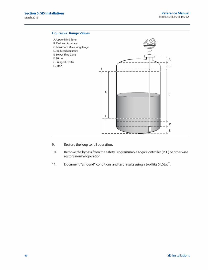
NoteThe applied level has to be between upper and lower range values, otherwise the device enters alarm mode. If level is outside maximum measuring range, the level reading accuracy may be reduced. For best performance, use the 4-20 mA range points as calibration points. See Figure 6-2 for range values.
RRM: AMS Device Manager and Field Communicator:
a. Go to Setup > Output > Analog Out 1 and select Loop test.
b. Enter current value representing low alarm current.
c. Select Start to output current.
d. Verify that analog output current is correct.
e. Verify that terminal voltage is correct. See values in Table 6-1.
f. Select Stop to end loop test.
a. Go to Configure > Manual Setup > Device Setup > Output.
For HART Device Revision 3: Go to Configure/Setup > Analog Output > Analog Out.
b. Select Loop Test > Other.
c. Enter current value representing low alarm current.
d. Verify that analog output current is correct.
e. Verify that terminal voltage is correct. See values in Table 6-1.
f. Select Abort to end loop test.
RRM: AMS Device Manager and Field Communicator:
a. In the Tools menu, select Lock/Unlock Configuration Area.
b. Enter Password to lock.
a. Go to Configure > Manual Setup > Device Setup > Security.
For HART Device Revision 3: go to Device Diagnostics > Tools > General.
b. Select Write Protect and follow the instructions.
39SIS Installations
Reference Manual 00809-1600-4530, Rev AA
Section 6: SIS InstallationsMarch 2015
Figure 6-2. Range Values
9. Restore the loop to full operation.
10. Remove the bypass from the safety Programmable Logic Controller (PLC) or otherwise restore normal operation.
11. Document “as found” conditions and test results using a tool like SILStat™.
A
B
C
D
E
F
G
H
A. Upper Blind ZoneB. Reduced AccuracyC. Maximum Measuring RangeD. Reduced AccuracyE. Lower Blind ZoneF. 20mAG. Range 0 -100%H. 4mA
40 SIS Installations
Reference Manual 00809-1600-4530, Rev AA
Appendix A: Commissioning ChecklistMarch 2015
Appendix A Commissioning Checklist
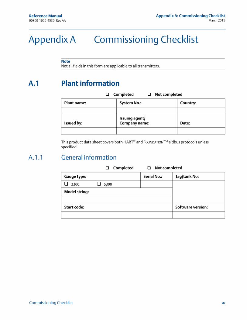
NoteNot all fields in this form are applicable to all transmitters.
A.1 Plant information
This product data sheet covers both HART® and FOUNDATION™ fieldbus protocols unless specified.
A.1.1 General information
Completed Not completed
Plant name: System No.: Country:
Issued by:Issuing agent/Company name: Date:
Completed Not completed
Gauge type: Serial No.: Tag/tank No:
3300 5300
Model string:
Start code: Software version:
41Commissioning Checklist
Reference Manual 00809-1600-4530, Rev AA
Appendix A: Commissioning ChecklistMarch 2015
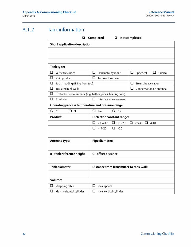
A.1.2 Tank information
Completed Not completed
Short application description:
Tank type:
Vertical cylinder Horizontal cylinder Spherical Cubical
Solid product Turbulent surface
Splash loading (filling from top) Steam/heavy vapor
Insulated tank walls Condensation on antenna
Obstacles below antenna (e.g. baffles, pipes, heating coils)
Emulsion Interface measurement
Operating process temperature and pressure range:
°C °F bar psi
Product: Dielectric constant range:
< 1.4-1.9 1.9-2.5 2.5-4 4-10
>11-20 >20
Antenna type: Pipe diameter:
R - tank reference height G - offset distance
Tank diameter: Distance from transmitter to tank wall:
Volume:
Strapping table Ideal sphere
Ideal horizontal cylinder Ideal vertical cylinder
42 Commissioning Checklist
Reference Manual 00809-1600-4530, Rev AA
Appendix A: Commissioning ChecklistMarch 2015
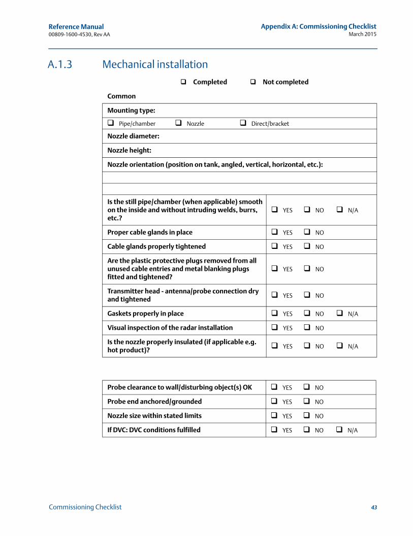
A.1.3 Mechanical installation
Completed Not completed
Common
Mounting type:
Pipe/chamber Nozzle Direct/bracket
Nozzle diameter:
Nozzle height:
Nozzle orientation (position on tank, angled, vertical, horizontal, etc.):
Is the still pipe/chamber (when applicable) smooth on the inside and without intruding welds, burrs, etc.?
YES NO N/A
Proper cable glands in place YES NO
Cable glands properly tightened YES NO
Are the plastic protective plugs removed from all unused cable entries and metal blanking plugs fitted and tightened?
YES NO
Transmitter head - antenna/probe connection dry and tightened YES NO
Gaskets properly in place YES NO N/A
Visual inspection of the radar installation YES NO
Is the nozzle properly insulated (if applicable e.g. hot product)? YES NO N/A
Probe clearance to wall/disturbing object(s) OK YES NO
Probe end anchored/grounded YES NO
Nozzle size within stated limits YES NO
If DVC: DVC conditions fulfilled YES NO N/A
43Commissioning Checklist

Reference Manual 00809-1600-4530, Rev AA
Appendix A: Commissioning ChecklistMarch 2015
A.1.4 Electrical installation
Completed Not completed
Power supply within limits YES NO
Voltage measured at the terminal at the transmitter:
Groundings according to manual and local regulations YES NO
Ground check done with multimeter YES NO
Voltage measured between - terminal and ground: YES NO
Voltage measured between + terminal and ground: YES NO
Resistance measured between transmitter head external ground terminal and tank ground terminal:
YES NO
Is the cable shield connected according to guidelines in the Reference Manual and local regulations?
YES NO
Is the transmitter head external ground terminal connected according to guidelines in the Reference Manual and to local regulations?
YES NO
Type and size of cable used for the communication:
Is the lid to the terminal compartment properly closed? YES NO
Is the product’s Ex classification in accordance with requirements? YES NO
44 Commissioning Checklist
Reference Manual 00809-1600-4530, Rev AA
Appendix A: Commissioning ChecklistMarch 2015
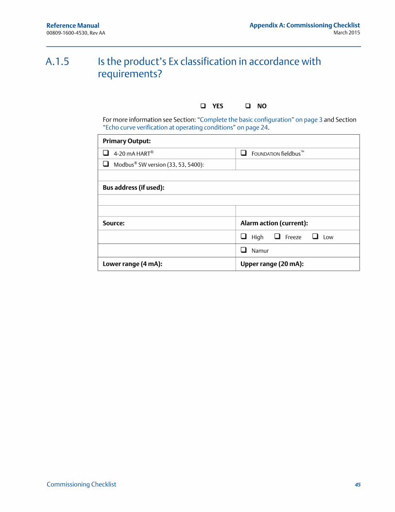
A.1.5 Is the product’s Ex classification in accordance with requirements?
YES NO
For more information see Section: “Complete the basic configuration” on page 3 and Section “Echo curve verification at operating conditions” on page 24.
Primary Output:
4-20 mA HART® FOUNDATION fieldbus™
Modbus® SW version (33, 53, 5400):
Bus address (if used):
Source: Alarm action (current):
High Freeze Low
Namur
Lower range (4 mA): Upper range (20 mA):
45Commissioning Checklist
Reference Manual 00809-1600-4530, Rev AA
Appendix A: Commissioning ChecklistMarch 2015
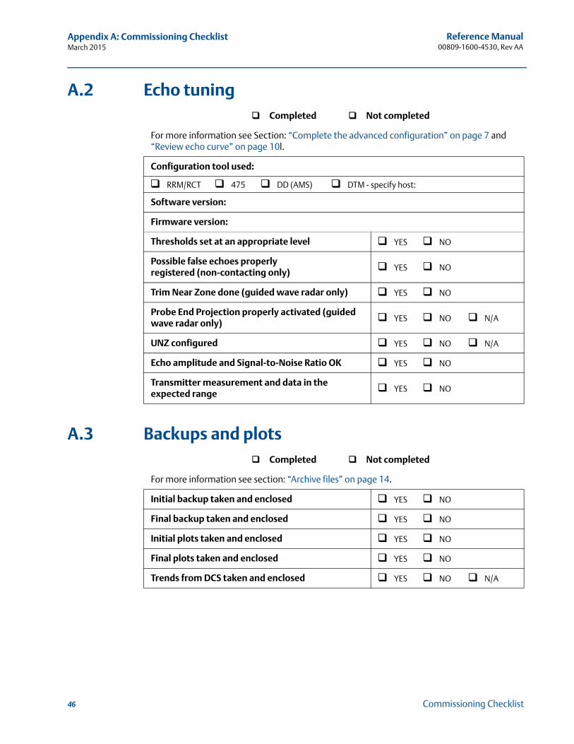
A.2 Echo tuning
A.3 Backups and plots
Completed Not completed
For more information see Section: “Complete the advanced configuration” on page 7 and “Review echo curve” on page 10l.
Configuration tool used:
RRM/RCT 475 DD (AMS) DTM - specify host:
Software version:
Firmware version:
Thresholds set at an appropriate level YES NO
Possible false echoes properlyregistered (non-contacting only) YES NO
Trim Near Zone done (guided wave radar only) YES NO
Probe End Projection properly activated (guided wave radar only) YES NO N/A
UNZ configured YES NO N/A
Echo amplitude and Signal-to-Noise Ratio OK YES NO
Transmitter measurement and data in the expected range YES NO
Completed Not completed
For more information see section: “Archive files” on page 14.
Initial backup taken and enclosed YES NO
Final backup taken and enclosed YES NO
Initial plots taken and enclosed YES NO
Final plots taken and enclosed YES NO
Trends from DCS taken and enclosed YES NO N/A
46 Commissioning Checklist
Reference Manual 00809-1600-4530, Rev AA
Appendix A: Commissioning ChecklistMarch 2015
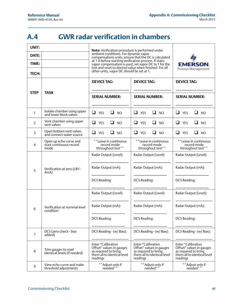
A.4 GWR radar verification in chambersUNIT:
Note: Verification procedure is performed under ambient conditions. For dynamic vapor compensations units, ensure that the DC is calculated at 1.0 before starting verification process. If static vapor compensation is used, set vapor DC to 1 for the test and reset to desired value when finished. For all other units, vapor DC should be set at 1.
DATE:
TIME:
TECH:
STEP TASK
DEVICE TAG:
__________________
DEVICE TAG:
__________________
DEVICE TAG:
__________________
SERIAL NUMBER:
__________________
SERIAL NUMBER:
__________________
SERIAL NUMBER:
__________________
1 Isolate chamber using upper and lower block valves YES NO YES NO YES NO
2 Vent chamber using upper vent valves YES NO YES NO YES NO
3 Open bottom vent valves and connect water source YES NO YES NO YES NO
4Open up echo curve and start continuous record mode
**Leave in continuous record mode
throughout test**
**Leave in continuous record mode
throughout test**
**Leave in continuous record mode
throughout test**
5 Verification at zero (LRV - 4mA)
Radar Output (Level):
____________________
Radar Output (mA):
__________________
DCS Reading:
__________________
Radar Output (Level):
____________________
Radar Output (mA):
__________________
DCS Reading:
__________________
Radar Output (Level):
____________________
Radar Output (mA):
__________________
DCS Reading:
__________________
6 Verification at nominal level condition
Radar Output (Level):
____________________
Radar Output (mA):
__________________
DCS Reading:
__________________
Radar Output (Level):
____________________
Radar Output (mA):
__________________
DCS Reading:
__________________
Radar Output (Level):
____________________
Radar Output (mA):
____________________
DCS Reading:
____________________
7DCS (zero check - bias added)
DCS Reading - (w/ Bias):
____________________
DCS Reading - (w/ Bias):
____________________
DCS Reading - (w/ Bias):
____________________
8 Trim gauges to read identical levels (if needed)
Enter “Calibration Offset” values in gauges as required to bring them all to identical level readings
Enter “Calibration Offset” values in gauges as required to bring them all to identical level readings
Enter “Calibration Offset” values in gauges as required to bring them all to identical level readings
9 View echo curve and make threshold adjustments
**Adjust only ifneeded**
**Adjust only ifneeded**
**Adjust only ifneeded**
47Commissioning Checklist
Reference Manual 00809-1600-4530, Rev AA
Appendix A: Commissioning ChecklistMarch 2015
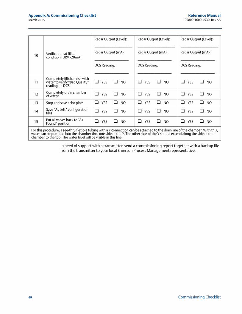
In need of support with a transmitter, send a commissioning report together with a backup file from the transmitter to your local Emerson Process Management representative.
10 Verification at filled condition (URV -20mA)
Radar Output (Level):
____________________
Radar Output (mA):
__________________
DCS Reading:
__________________
Radar Output (Level):
____________________
Radar Output (mA):
__________________
DCS Reading:
__________________
Radar Output (Level):
____________________
Radar Output (mA):
__________________
DCS Reading:
__________________
11Completely fill chamber with water to verify “Bad Quality” reading on DCS
YES NO YES NO YES NO
12 Completely drain chamber of water YES NO YES NO YES NO
13 Stop and save echo plots YES NO YES NO YES NO
14 Save “As Left” configuration files YES NO YES NO YES NO
15 Put all valves back to “As Found” position YES NO YES NO YES NO
For this procedure, a see-thru flexible tubing with a Y connection can be attached to the drain line of the chamber. With this, water can be pumped into the chamber thru one side of the Y. The other side of the Y should extend along the side of the chamber to the top. The water level will be visible in this line.
48 Commissioning Checklist

Reference Manual 00809-1600-4530, Rev AA
March 2015
49

Reference Manual00809-1600-4530, Rev AA
March 2015
Rosemount World Headquarters
Emerson Process Management 6021 Innovation BlvdShakopee, MN 55379, USA+1 800 999 9307 or +1 952 906 8888+1 952 949 7001 [email protected]
North America Regional OfficeEmerson Process Management 8200 Market Blvd.Chanhassen, MN 55317, USA
+1 800 999 9307 or +1 952 906 8888+1 952 949 7001 [email protected]
Latin America Regional OfficeEmerson Process Management 1300 Concord Terrace, Suite 400Sunrise, Florida, 33323, USA
+1 954 846 5030+1 954 846 [email protected]
Europe Regional OfficeEmerson Process Management Europe GmbHNeuhofstrasse 19a P.O. Box 1046CH 6340 BaarSwitzerland
+41 (0) 41 768 6111+41 (0) 41 768 6300 [email protected]
Asia Pacific Regional OfficeEmerson Process Management Asia Pacific Pte Ltd1 Pandan CrescentSingapore 128461
+65 6777 8211+65 6777 0947 [email protected]
Middle East and Africa Regional OfficeEmerson Process Management Emerson FZE P.O. Box 17033,Jebel Ali Free Zone - South 2Dubai, United Arab Emirates
+971 4 8118100+971 4 8865465 [email protected]
Standard Terms and Conditions of Sale can be found at: www.rosemount.com\terms_of_sale.The Emerson logo is a trademark and service mark of Emerson Electric Co.Rosemount and Rosemount logotype are registered trademarks of Rosemount Inc.HART is a registered trademark of the FieldComm Group.FOUNDATION fieldbus is a trademark of the FieldComm Group.AMS is a registered trademark of Emerson Electrical Co.DeltaV is a trademark of one of the Emerson Process Management group of companies.Modbus is a registered trademark of Modicon Inc.All other marks are the property of their respective owners.© 2015 Rosemount Inc. All rights reserved.